Embed Size (px)
Citation preview

Form P5710
PARTS, OPERATION AND MAINTENANCE MANUALfor
MODEL BU7A AIR WINCH
(Dwg. MHP1233)
Form P5710Edition 15May 200103523115© 2001 Ingersoll-Rand Company
READ THIS MANUAL BEFORE USING THESE PRODUCTS. This manualcontains important safety, installation, operation and maintenanceinformation. Make this manual available to all persons responsible for theoperation, installation and maintenance of these products.
Do not use this Air Winch for lifting, supporting, or transporting people or lifting orsupporting loads over people.
Always operate, inspect and maintain this Air Winch in accordance with AmericanNational Standards Institute safety code (ASME B30.7) and any other applicable safetycodes and regulations.

2 P5710 - Edition 15
TABLE OF CONTENTS
Description Page No.
Safety InformationDanger, Warning, Caution and Notice .................................................................................................................................................................3Safety Summary...................................................................................................................................................................................................3Safe Operating Instructions .................................................................................................................................................................................4Warning Tags .......................................................................................................................................................................................................4
SpecificationsDescription...........................................................................................................................................................................................................5Model Code Explanation .....................................................................................................................................................................................5Performance Graphs ............................................................................................................................................................................................6
InstallationMounting..............................................................................................................................................................................................................7Wire Rope ............................................................................................................................................................................................................7Air Supply............................................................................................................................................................................................................8Initial Operating Checks ....................................................................................................................................................................................10
OperationWinch Controls ..................................................................................................................................................................................................11Winch Brakes .....................................................................................................................................................................................................11Free Spool Clutch ..............................................................................................................................................................................................12Emergency Stop Device.....................................................................................................................................................................................12
InspectionRecords and Reports ..........................................................................................................................................................................................13Frequent Inspection............................................................................................................................................................................................13Periodic Inspection ............................................................................................................................................................................................13Winches Not in Regular Use..............................................................................................................................................................................14Inspection and Maintenance Report ..................................................................................................................................................................15
LubricationMotor .................................................................................................................................................................................................................16Gear Case ...........................................................................................................................................................................................................16Seals and Bearings .............................................................................................................................................................................................16Wire Rope ..........................................................................................................................................................................................................16
TroubleshootingTroubleshooting .................................................................................................................................................................................................17
MaintenanceMaintenance Intervals ........................................................................................................................................................................................18Disassembly .......................................................................................................................................................................................................19Cleaning, Inspection and Repair ........................................................................................................................................................................21Assembly ...........................................................................................................................................................................................................22Testing................................................................................................................................................................................................................25
Parts Drawings and Parts ListWinch Assembly Parts Drawing ........................................................................................................................................................................26Winch Assembly Parts List................................................................................................................................................................................27Kits, Special Tools and Accessories ..................................................................................................................................................................29Automatic Brake Assembly Drawings and Parts List........................................................................................................................................30Remote Pendant Throttle Handle Drawing and Parts List.................................................................................................................................38Shuttle Valve Chest Assembly Drawing ............................................................................................................................................................32Shuttle Valve Chest Assembly Parts List...........................................................................................................................................................33Remote Control Stop Valve Assembly Drawing ...............................................................................................................................................34Drum Guard Assembly Drawing and Parts List ................................................................................................................................................35Stop Valve and Muffler Assembly Drawings and Parts Lists ............................................................................................................................36Label Locations Drawing and Parts List............................................................................................................................................................39Construction Cage Drawing and Parts List........................................................................................................................................................40Winch Upgrades.................................................................................................................................................................................................41Additional Reference Material...........................................................................................................................................................................41Parts Ordering Information ................................................................................................................................................................................42Warranty.............................................................................................................................................................................................................43
P5710 - Edition 15 3
SAFETY INFORMATION
This manual provides important information for all personnel involved with the safe installation, operation and proper maintenance of this product. Even if you feel you are familiar with this or similar equipment, you should read this manual before operating the winch.
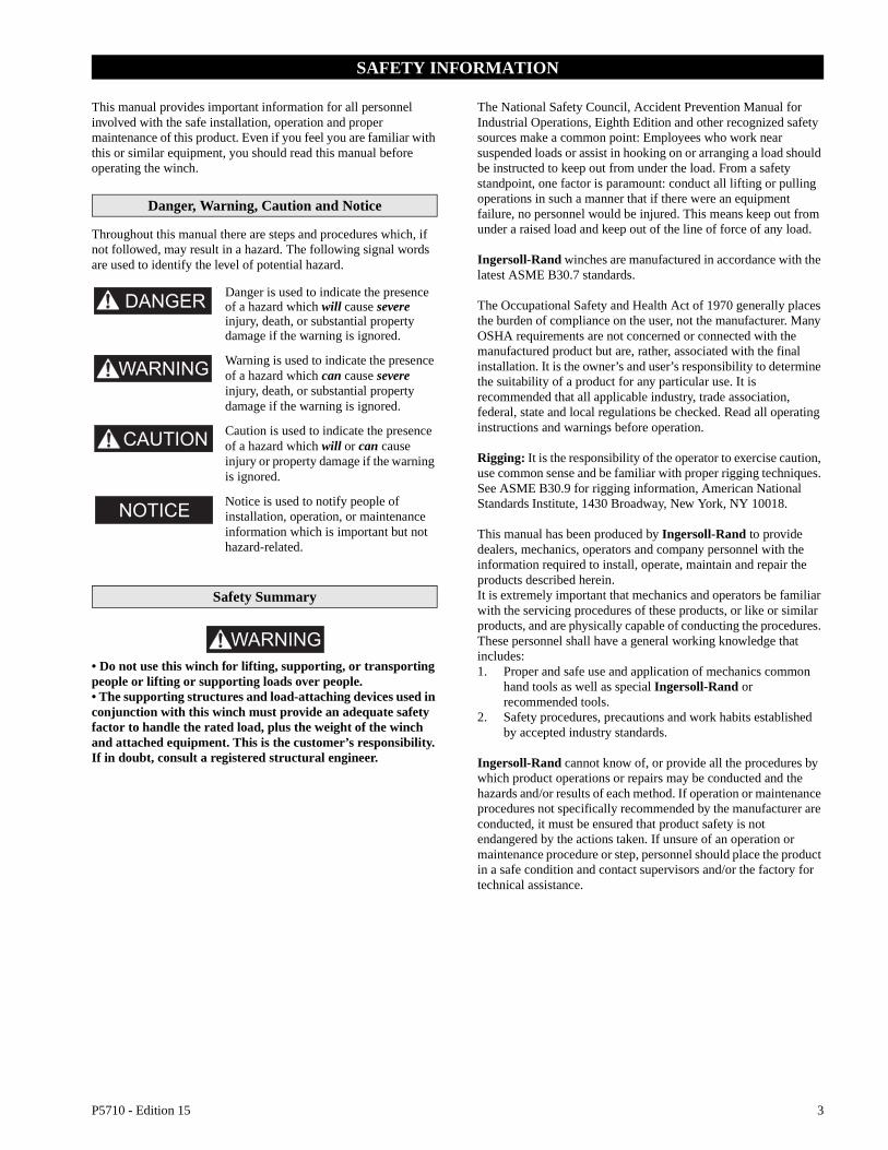
Danger, Warning, Caution and Notice
Throughout this manual there are steps and procedures which, if not followed, may result in a hazard. The following signal words are used to identify the level of potential hazard.
Danger is used to indicate the presence of a hazard which will cause severe injury, death, or substantial property damage if the warning is ignored.
Warning is used to indicate the presence of a hazard which can cause severe injury, death, or substantial property damage if the warning is ignored.
Caution is used to indicate the presence of a hazard which will or can cause injury or property damage if the warning is ignored.
Notice is used to notify people of installation, operation, or maintenance information which is important but not hazard-related.
Safety Summary
• Do not use this winch for lifting, supporting, or transporting people or lifting or supporting loads over people.• The supporting structures and load-attaching devices used in conjunction with this winch must provide an adequate safety factor to handle the rated load, plus the weight of the winch and attached equipment. This is the customer’s responsibility. If in doubt, consult a registered structural engineer.
The National Safety Council, Accident Prevention Manual for Industrial Operations, Eighth Edition and other recognized safety sources make a common point: Employees who work near suspended loads or assist in hooking on or arranging a load should be instructed to keep out from under the load. From a safety standpoint, one factor is paramount: conduct all lifting or pulling operations in such a manner that if there were an equipment failure, no personnel would be injured. This means keep out from under a raised load and keep out of the line of force of any load.
Ingersoll-Rand winches are manufactured in accordance with the latest ASME B30.7 standards.
The Occupational Safety and Health Act of 1970 generally places the burden of compliance on the user, not the manufacturer. Many OSHA requirements are not concerned or connected with the manufactured product but are, rather, associated with the final installation. It is the owner’s and user’s responsibility to determine the suitability of a product for any particular use. It is recommended that all applicable industry, trade association, federal, state and local regulations be checked. Read all operating instructions and warnings before operation.
Rigging: It is the responsibility of the operator to exercise caution, use common sense and be familiar with proper rigging techniques. See ASME B30.9 for rigging information, American National Standards Institute, 1430 Broadway, New York, NY 10018.
This manual has been produced by Ingersoll-Rand to provide dealers, mechanics, operators and company personnel with the information required to install, operate, maintain and repair the products described herein.It is extremely important that mechanics and operators be familiar with the servicing procedures of these products, or like or similar products, and are physically capable of conducting the procedures. These personnel shall have a general working knowledge that includes:1. Proper and safe use and application of mechanics common
hand tools as well as special Ingersoll-Rand or recommended tools.
2. Safety procedures, precautions and work habits established by accepted industry standards.
Ingersoll-Rand cannot know of, or provide all the procedures by which product operations or repairs may be conducted and the hazards and/or results of each method. If operation or maintenance procedures not specifically recommended by the manufacturer are conducted, it must be ensured that product safety is not endangered by the actions taken. If unsure of an operation or maintenance procedure or step, personnel should place the product in a safe condition and contact supervisors and/or the factory for technical assistance.

4 P5710 - Edition 15
SAFE OPERATING INSTRUCTIONS
The following warnings and operating instructions have been adapted in part from American National (Safety) Standard ASME B30.7 and are intended to avoid unsafe operating practices which might lead to injury or property damage.
Ingersoll-Rand recognizes that most companies who use winches have a safety program in force at their facility. In the event that some conflict exists between a rule set forth in this publication and a similar rule already set by an individual company, the more stringent of the two should take precedence.
Safe Operating Instructions are provided to make an operator aware of dangerous practices to avoid and are not necessarily limited to the following list. Refer to specific sections in the manual for additional safety information.
1. Only allow personnel trained in safety and operation of this winch to operate and maintain this product.
2. Only operate a winch if you are physically fit to do so.3. When a “DO NOT OPERATE” sign is placed on the winch,
or controls, do not operate the winch until the sign has been removed by designated personnel.
4. Before each shift, the operator should inspect the winch for wear and damage. Never use a winch that inspection indicates is worn or damaged.
5. Never lift a load greater than the rated capacity of the winch. Refer to “SPECIFICATIONS” section.
6. Keep hands, clothing, etc., clear of moving parts.7. Never place your hand in the throat area of a hook or near
wire rope spooling onto or off of the winch drum.
8. Always rig loads properly and carefully.9. Be certain the load is properly seated in the saddle of the
hook. Do not support a load on the tip of a hook.10. Do not “side pull” or “yard”.11. Make sure everyone is clear of the load path and there are no
objects in the way of the load. Do not lift a load over people. 12. Never use the winch for lifting or lowering people, and never
allow anyone to stand on a suspended load.13. Ease the slack out of the wire rope when starting a lift or pull.
Do not jerk the load.14. Do not swing a suspended load.15. Never leave a suspended load unattended.16. Pay attention to the load at all times when operating the
winch.17. After use or when in a non-operational mode, the winch
should be secured against unauthorized and unwarranted use.18. The operator must maintain an unobstructed view of the load
at all times.19. Never use the winch wire rope as a sling.20. Never operate a winch with twisted, kinked or damaged wire
rope.21. Shut off air supply before leaving winch unattended.22. Do not do anything you believe may be unsafe.23. Never splice a sling chain by inserting a bolt between links.24. Do not force a chain or hook into place by hammering. Do
not insert the point of the hook into a chain link.25. Do not expose the sling chain to freezing temperatures, and
do not apply sudden loads to a cold chain.
WARNING TAGS
Each winch is shipped from the factory with the warning tags shown. If tags are not attached to your winch, order new tags and install them. Refer to parts list for part number. Tags are shown smaller than actual size.
WARNING
?
Read the latest edition of ASME B30.7.Comply with other federal, state and local rules.
P/N 71056410/Afor winches
Failure to follow thesewarnings may result indeath, severe injury orproperty damage:
Do not operatethis winch beforereading operationand maintenancemanual.
Do not lift people or loadsover people.
Do not lift more than ratedload.
Do not allow less than threewraps of wire rope to remainon drum at all times.
Do not operate a damagedor malfunctioning winch.
Do not remove or obscurewarning labels.

P5710 - Edition 15 5
SPECIFICATIONS
Description
The BU7A winch is powered by a radial piston air motor. The output from the motor is transferred through the drum by the drive shaft. The drive shaft rotates a series of connected spur gears which form a reduction assembly. Output from the reduction assembly drives the wire rope drum. Spur gears are not inherently self-locking as other types of gears are, therefore the brake must be applied whenever there is a load attached to the load line. The winch is also equipped with a free spool feature.
• The free spool feature must only be used with a manual brake. Use of a manual brake is the only way to maintain control of the load line.
The free spool feature consists of a spring detented clutch jaw connecting the final drive shaft and final spur gear in the reduction assembly. When the clutch jaw is disconnected, the drum becomes disconnected from the reduction gear assembly and motor and is free to rotate in either direction.
(Dwg. MHP1286)
Model Code Explanation
Example: BU7APTAB BU7A PTAB
Series = BU7AOptions
AB = Automatic BrakeRC = Remote ControlRCAB = Remote Control and Automatic BrakePTAB = Remote Pendant Control and Automatic BrakeZP = Zinc-plated-E = Compliance with the European Machinery DirectiveP = Marine 812 FinishZ = Sandblast and Carbozinc PrimerE = Construction CageR = Natural Gas Operation*
* Not Covered in this manual.
Manual Brake
Wire RopeDrum
Motor
Throttle Handle
Free SpoolClutch
Gear Case

6 P5710 - Edition 15
BU7A Performance Graph BU7APTAB Performance Graph
(Dwg. MHP2262) (Dwg. MHP2263)
1600
1400
1200
1000
800
600
200
00 6
Line
Pul
l (Lb
s)
12 18 24 30 36 42Line Speed (ft/min)
48 54 60 66 72 78 84 90 96 102
30
20
40
50
Air C
onsumption (scfm
)
60
70
400
1st wrap line pull
mid drum
full drum
1st wrap flo
w
mid dru
m
full drum
1400
1200
1000
800
600
400
200
00 6
Line
Pul
l (Lb
s)
12 18 24 30 36 42Line Speed (ft/min)
48 54 60 66 72 78 84 90 96 102
30
20
40
50
Air C
onsumption (scfm
)
60
701st wrap line pull
mid drum
full drum
1st wrap flo
w
mid dru
m
full drum
General SpecificationsModel
BU7A BU7APTAB
Air SystemRated Operating Pressure 90 psig (6.3 bar)
Consumption Volume(at rated pressure)
50 scfm 1.4 cu. m/min 50 scfm 1.4 cu. m/min
Rated Performance(at rated pressure/volume)
Mid Drum Line Pull 1,000 lbs 454 kgs 1,000 lbs 454 kgs
Mid Drum Line Speed 43 fpm 13 m/min 37 fpm 11 m/min
Max Stall Pull - 1st Layer 1,950 lbs 886 kgs 1,950 lbs 886 kgs
Net Weight 75 lbs 34 kgs 108 lbs 49 kgs
Air Motor Pipe Inlet Size 1/2 inch 13 mm 1/2 inch 13 mm
Air System Hose Size 3/4 inch 19 mm 3/4 inch 19 mm
Wire Rope Anchor Hole Diameter 11/32 inch 8.7 mm 11/32 inch 8.7 mm
Drum Flange Diameter 8-1/2 inch (216 mm)
Drum Length (between flanges) 4-1/2 inch (114 mm)
Motor HP 1.6
Drum Wire Rope StorageCapacity *
(feet/metres)
Wire Rope Diameter
1/4 inch ** 6 mm 5/16 inch 8 mm
158 ft 48 m 105 ft 32 m
Factors for determining STALL and LINE PULL at various air pressure.To obtain performances at operating pressures other than 90 psi, select the load or speed rating required from the applicable performance graph and multiply that value by the factor corresponding to the operating pressure from the table.Example: Model BU7A at 750 lbs with 70 psi and drum half full.To determine speed from curve:50 fpm x 0.72 = 36 fpm.
Air Pressure (psi) Stall Factor Wire Rope Speed Factor
60 0.67 0.58
70 0.78 0.72
80 0.89 0.86
90 1.00 1.00
100 1.11 1.14
* Based on ASME B30.7 standards which require top layer to be at least 1/2 in. (13 mm) below drum flange diameter.* Recommended drum working storage capacity is 80% of values shown.
** Recommended wire rope size.

P5710 - Edition 15 7
INSTALLATION
Prior to installing the winch, carefully inspect it for possible shipping damage. Winches are supplied from the factory drained of oil. Add oil prior to winch operation. Check oil levels and adjust as necessary. Use proper type of oil as recommended in “LUBRICATION” section.
• Owners and users are advised to examine specific, local or other regulations, including American National Standards Institute and/or OSHA Regulations which may apply to a particular type of use of this product before installing or putting winch to use.
Mounting
Mount winch with longitudinal center line horizontal and vent cap (25) at top vertical center. The winch will not function properly if the longitudinal center line is tilted more than 10° or if winch is rotated so that vent cap is more than 20° off top vertical center.
For mounting on a vertical surface or for inverted mounting, the motor case (28) can be rotated on the motor mounting bracket (79) to any one of four different positions. This feature allows the motor assembly to be positioned with the vent cap (25) on top. To change the position of the motor assembly, drain the oil from the motor case, unscrew the eight motor case capscrews (29) and rotate the motor assembly to suit the mounting. Refer to Dwg. MHP0548 on page 7. Ensure clear unrestricted access is always available to control and brake levers.
Bolt Hole Dimensions
(Dwg. MHP0548)
1. Do not weld to any part of winch.2. The winch mounting surface must be flat and of sufficient
strength to handle the rated load plus the weight of the winch and attached equipment. An inadequate foundation may cause distortion or twisting of the winch resulting in winch damage.
3. Make sure mounting surface is flat to within 1/16 inch (2.0 mm). Shim if necessary.
4. Mounting bolts must be 1/2 inch - NC (14 mm) Grade 8 or better. Use self-locking nuts or nuts with lockwashers.
5. Tighten mounting bolts evenly and torque to 110 ft lbs (15.2 kg m) for dry thread fasteners. If the fasteners are plated,
lubricated or a thread locking compound is used, torque to 80 ft lbs (11.0 kg m).
6. When a lead sheave is used, it must be aligned with the center of the drum. The diameter of the lead sheave must be at least 18 times the diameter of the wire rope.
7. Maintain a fleet angle between the sheave and winch of no more than 1-1/2°. The lead sheave must be on a center line with the drum and be at least 7.2 feet (2.2 metres) from the drum. Refer to Dwg. MHP0498, Note 3 on page 7.
Wire Rope and Fleet Angle Installation
(Dwg. MHP0498)
Notes: 1. Maintain a minimum of 3 tight wraps of wire rope on the
drum at all times.2. For lifting applications, ensure top layer of wire rope is at
least 1/2 in. (13 mm) below edge of drum flange.3. For correct fleet angle, maintain a minimum of 1.6 feet (0.5
metre) per inch of drum length. Example: for a 7 inch drum length, locate the lead sheave at least 11.2 feet (3.5 metres) from drum.
Wire Rope
• Maintain at least 3 tight wraps of wire rope on the drum at all times. Refer to Dwg. MHP0498 Note 1 on page 7.
Wire Rope Selection
Consult a reputable wire rope manufacturer or distributor for assistance in selecting the appropriate type and size of wire rope and, where necessary, a protective coating. Use a wire rope which provides an adequate safety factor to handle the actual working load and that meets all applicable industry, trade association, federal, state and local regulations.When considering wire rope requirements the actual working load must include not only the static or dead load but also loads resulting from acceleration, retardation and shock load. Consideration must also be given to the size of the winch wire rope drum, sheaves and method of reeving. Wire rope construction

8 P5710 - Edition 15
must be 6 X 19 or 6 X 37 Extra Improved IWRC right lay to assist spooling. Refer to Table 1 on page 8 for minimum and maximum recommended wire rope diameters.
For winches used in lifting applications, ensure that the top layer of the wire rope is a distance from the top of the drum flange that is equal to at least twice the diameter of the wire rope. For example: the top layer of a 8 mm wire rope must be at least 16 mm below the drum flange edge. Refer to Dwg. MHP0498, Note 2 on page 7.As a general rule for lifting applications, a minimum of 5:1 wire rope design factor is required with an 18:1 wire rope to drum diameter ratio. For pulling applications, a 3:1 wire rope design factor is required with a 15:1 wire rope to drum diameter ratio.
Safe Wire Rope Handling Procedures
1. Always use gloves when handling wire rope.2. Never use wire rope which is frayed or kinked.3. Never use wire rope as a sling.4. Always ensure wire rope is correctly spooled and the first
layer is tight against the drum.5. Always follow wire rope manufacturer’s recommendations
on use and maintenance of wire rope.
Installing Wire Rope
Refer to Dwg. MHP1288 on page 8.1. Cut wire rope to length and fuse end to prevent fraying of
strands in accordance with the wire rope manufacturer’s instructions.
2. Feed the fused end of the wire rope into the wire rope anchor hole, past the two anchor screws, and position the end just beneath the drum surface.
3. Apply the wire rope so that it winds over the top when the drum is rotated in a direction that is clockwise when facing the gear end of the winch. This is indicated by an arrow on the gear case.
4. Secure by tightening both anchor screws. Make sure the anchor screws are below the surface of the drum when tightened.
(Dwg. MHP1288)
• Ensure the first wrap of wire rope is tight and lies flush against the drum flange.• The wire rope should be applied to the drum so that it overwinds when the drum rotates in a clockwise direction when facing the gear end of the winch. This is indicated by an arrow on the gear case.
Wire Rope Spooling
To compensate for uneven spooling and the decrease in line pull capacity as the drum fills up, use as short a wire rope as practical. When rewinding apply tension to the end of the wire rope to eliminate line slack. This helps achieve level winding and tight spooling.
Rigging
Make sure all wire rope blocks, tackle and fasteners have a sufficient safety margin to handle the required load under all conditions. Do not allow wire rope to contact sharp edges or make sharp bends which will cause damage to wire rope, use a sheave. Refer to the wire rope manufacturer’s handbook for proper sizing, use and care of wire rope.
Safe Installation Procedures
1. Do not use wire rope as a ground (earth) for welding.2. Do not attach a welding electrode to winch or wire rope.3. Never run the wire rope over a sharp edge. Use a correctly
sized sheave.4. When a lead sheave is used, it must be aligned with the center
of the drum. Refer to Dwg. MHP0498 on page 7. The diameter of the lead sheave must be at least 18 times the diameter of the wire rope.
5. Always maintain at least three full, tight wraps of wire rope on the drum.
Air Supply
The air supply must be clean, free from moisture and lubricated to ensure optimum motor performance. Foreign particles, moisture and lack of lubrication are the primary causes of premature motor wear and breakdown. Using an air filter, lubricator and moisture separator will improve overall winch performance and reduce unscheduled downtime.
The air consumption is 50 scfm (1.4 cu.m/min.) at rated operating pressure of 90 psig (6.3 bar/630 kPa) at the winch motor inlet. If the air supply varies from what is recommended, winch performance will change.
Table 1
Minimum and Maximum Wire Rope Sizes
ModelMinimum Maximum
inch mm inch mm
BU7A 1/4 6 5/16 8
* Breaking Strength
Rope Size (in.) lbs kgs
Weightper ft(lbs)
Weightper metre
(kgs)
1/4 (0.25) 6800 3084 0.11 0.15
5/16 (0.31) 10540 4781 0.18 0.25
* Based on extra improved plow steel wire rope with independent wire rope core. ASME B30.7 requires a minimum of 3.5:1 design factor with 15:1 wire rope diameter to drum diameter for most applications (e.g. pulling/hauling and anchor handling). For lifting and lowering, a 5:1 design factor with an 18:1 wire rope diameter to drum diameter is required.

P5710 - Edition 15 9
Air Lines
The inside diameter of the winch air supply lines must not be less than the size shown in Table 2 on page 9. Prior to making final connections, all air supply lines should be purged with clean, moisture free air or nitrogen before connecting to winch inlet. Supply lines should be as short and straight as installation conditions will permit. Long transmission lines and excessive use of fittings, elbows, tees, globe valves etc. cause a reduction in pressure due to restrictions and surface friction in the lines.
Remote Control (Optional Feature)
Refer to Dwg. MHP1241 on page 9 for hose connection positions.
(Dwg. MHP1241)
Air Line Lubricator
Refer to Dwg. MHP0191 on page 9.Always use an air line lubricator with these motors. The lubricator must have an inlet and outlet at least as large as the inlet on the motor. Install the air line lubricator as close to the air inlet on the motor as possible.
• Lubricator must be located no more than 10 ft. (3 m) from the motor.• Shut off air supply before filling air line lubricator.
The air line lubricator should be replenished daily and set to provide 6 to 9 drops per minute of ISO VG 32 (10W) oil. A fine mist will be exhausted from the throttle control valve when the air line lubricator is functioning properly.
Air Line Filter
Refer to Dwg. MHP0191 on page 9.It is recommended that an air line strainer/filter be installed as close as practical to the motor air inlet port, but before the lubricator, to prevent dirt from entering the motor. The strainer/filter should provide 20 micron filtration and include a moisture trap. Clean the strainer/filter periodically to maintain its operating efficiency.
(Dwg. MHP0191)
Moisture in Air Lines
Moisture that reaches the air motor through air supply lines is a primary factor in determining the length of time between service overhauls. Moisture traps can help to eliminate moisture. Other methods, such as an air receiver which collects moisture before it reaches the motor, an aftercooler at the compressor that cools the air to condense and collect moisture prior to distribution through the supply lines are also helpful.
Motor
For optimum performance provide an air supply of 90 psig at 50 scfm (6.3 bar/630 kPa at 1.4 cu.m/min) for BU7A winches. The air motor should be installed as near as possible to the compressor or air receiver. Recommended pressures and volumes are measured at the point of entry to the air motor.
Table 2
Minimum Allowable Air Supply Line Sizes
Model inch mm
BU7A 3/4 19
Haul-inGreen
PayoutYellow
SupplyRed
WinchAir Supply
Haul-inGreen
SupplyRed
PayoutYellow

10 P5710 - Edition 15
Initial Operating Checks
Winches are tested for proper operation prior to leaving the factory. Before the winch is placed into service the following initial operating checks should be performed.1. Refer to the “LUBRICATION” section to ensure correct oil
level in air motor.2. When first running the motor, inject some light oil into the
inlet connection to provide initial lubrication.3. When first operating the winch it is recommended that the
motor be driven slowly in both directions for a few minutes.
Start-Up Procedures
For winches that have been in storage for a period of more than one month, the following start-up procedure is required:1. Refer to the “LUBRICATION” section to ensure correct oil
level in air motor.2. Give the winch an inspection conforming to the requirements
listed in “Winches Not in Regular Use” in the “INSPECTION” section.
3. Pour a small amount of ISO VG 32 (10W) oil in the motor inlet port.
4. Operate the motor for 10 seconds in both directions to flush out any impurities.
5. The winch is now ready for normal use.

P5710 - Edition 15 11
OPERATION
The four most important aspects of winch operation are:1. Follow all safety instructions when operating the winch.2. Allow only people trained in safety and operation of this
winch to operate this equipment.3. Subject each winch to a regular inspection and maintenance
procedure.4. Be aware of the winch capacity and weight of load at all
times.
• To avoid damage to the rigging, the structure supporting the rigging and the winch, do not “two-block”* the end of the wire rope.
* Two-blocking occurs when the winch wire rope is multi-reeved using two separate sheave blocks which are allowed to come into contact with each other during winch operation. When this occurs, extreme forces are exerted on the wire rope and sheave blocks, which may result in equipment and/or rigging failure.
• The winch is not designed or suitable for lifting, lowering or moving persons. Never lift loads over people.
Operators must be physically competent and have no health condition which might affect their ability to act. They must have good hearing, vision and depth perception. The winch operator must be carefully instructed in his duties and must understand the operation of the winch, including a study of the manufacturer’s literature. The operator must thoroughly understand proper methods of hitching loads and must have a good attitude regarding safety. It is the operator’s responsibility to refuse to operate the winch under unsafe conditions.
Winch Controls
A spring loaded, motor mounted, manual throttle control valve is supplied as a standard feature of this winch. Optional motor throttle controls are available. Refer to the model code on the winch nameplate and compare it to the “SPECIFICATIONS” section of this manual to determine your configuration. The throttle control provides operator control of the winch motor speed and direction of drum rotation.
Winch Mounted Live Air Throttle (standard feature)
Refer to Dwg. MHP1239 on page 11.The spring loaded manual control throttle mounts to the air motor.When viewed from the air motor end move the control throttle handle to the right (clockwise) to payout wire rope and to the left (counterclockwise) to haul-in wire rope.To ensure smooth operation of the winch sudden movements of the control valve should be avoided.
(Dwg. MHP1239)
Remote Live Air Pendant Throttle (optional feature)
Refer to Dwg. MHP1319 on page 11.Provides for remote winch control at distances of up to *15 feet (4.5 metres) away from the winch. The pendant control throttle is a two lever movable control station for winch operation. The winch control valve, located on the winch motor, controls the motor speed and direction of drum rotation. Direction of rotation is determined by the pendant lever depressed.
* For distances greater than 15 feet (4.5 metres) contact Technical Sales for control acceptability.
(Dwg. MHP1319)
Winch Brakes
Manual Drum Brake
The manual drum brake may be applied by pushing down on the handle (55) and released by pulling up. If handle is pushed down fully, it should lock in that position and prevent drum rotation until released by the operator. The brake must be kept properly adjusted to hold the required load. Refer to the “MAINTENANCE” section for brake adjustment.
Automatic Drum Brake
The brake band is operated by a spring loaded air cylinder. When control valve is actuated in any direction, air is applied to the brake cylinder causing the brake rod to extend and release the

12 P5710 - Edition 15
brake band. When control valve is returned to neutral, there is no air supply to the brake cylinder so the internal spring will retract the brake rod causing the brake lever to lock the brake band in position.For winches equipped with an automatic brake, always ensure that clutch jaw spacers (143) are installed.
Free Spool Clutch
• Do not engage clutch when motor is running or drum is spinning, as this produces a severe strain on parts.• Do not disengage clutch when winch is loaded. Be sure clutch is fully engaged before operating winch.
A jaw type clutch connects the gearing and drum. The function of the clutch is to disengage the rope drum from the motor so that the wire rope can be unwound from the drum by hand without working against the gearing and the compression of the motor. The clutch is engaged or disengaged by the clutch lever (54) which is located on the top of the gear case cover (76). When clutch is engaged the lever is locked by a detent to prevent disengagement. Detent is released by pressing down (toward base) on lever, after which the end can be swung outward from the winch, disengaging the clutch jaws. When clutch is in disengaged position it can be engaged by moving end of lever toward winch. It may be necessary to open the throttle a slight amount to position the jaws for engagement.
• Do not use free spool clutch feature in combination with automatic brake. Use of winches with free spool clutch and automatic brake can result in severe injury, death or property damage.
Emergency Stop Device
Refer to Dwgs. MHP1530 and MHP1546 on page 12.The emergency stop device is located at the air inlet of the winch on local control (winch mounted throttle) models and on the pendant of remote control models. When the emergency stop is activated, winch drum rotation ceases immediately.1. To start winch operation, press the “ON” button.2. To operate winch, press the “Haul-in” or “Payout” control
lever.3. In the event of an emergency, all winch operation can be
stopped by pushing the emergency stop button. This will prevent air from reaching the winch motor, thereby stopping drum movement.
4. To restart the winch after the emergency stop has been activated, press the “ON” button.
(Dwg. MHP1530)
(Dwg. MHP1546)
“EMERGENCY STOP”Button
“ON” Button
AirInlet
P5710 - Edition 15 13
INSPECTION
Inspection information is based in part on American National Standards Institute Safety Codes (ASME B30.7).
• All new, altered or modified equipment should be inspected and tested by personnel instructed in safety, operation and maintenance of this equipment to ensure safe operation at rated specifications before placing equipment in service. • Never use a winch that inspection indicates is damaged.
Frequent and periodic inspections should be performed on equipment in regular service. Frequent inspections are visual examinations performed by operators or personnel trained in safety and operation of this equipment and include observations made during routine winch operation. Periodic inspections are thorough inspections conducted by personnel trained in the safety, operation and maintenance of this equipment.ASME B30.7 states inspection intervals depend upon the nature of the critical components of the equipment and the severity of usage. The inspection intervals recommended in this manual are based on intermittent operation of the winch eight hours each day, five days per week, in an environment relatively free of dust, moisture and corrosive fumes. If the winch is operated almost continuously or more than the eight hours each day, more frequent inspections will be required.Careful inspection on a regular basis will reveal potentially dangerous conditions while still in the early stages, allowing corrective action to be taken before the condition becomes dangerous.Deficiencies revealed through inspection, or noted during operation, must be reported to designated personnel instructed in safety, operation and maintenance of this equipment. A determination as to whether a condition constitutes a safety hazard must be made, and the correction of noted safety hazards accomplished and documented by written report before placing the equipment in service.
Records and Reports
Inspection records, listing all points requiring periodic inspection should be maintained for all load bearing equipment. Written reports, based on severity of service, should be made on the condition of critical parts as a method of documenting periodic inspections. These reports should be dated, signed by the person who performed the inspection, and kept on file where they are readily available for review.
Wire Rope Reports
Records should be maintained as part of a long-range wire rope inspection program. Records should include the condition of wire rope removed from service. Accurate records will establish a relationship between visual observations noted during frequent inspections and the actual condition of wire rope as determined by periodic inspections.
Frequent Inspection
On equipment in continuous service, frequent inspection should be made by operators at the beginning of each shift. In addition, visual inspections should be conducted during regular operation for indications of damage or evidence of malfunction.
1. WINCH. Prior to operation, visually inspect winch housing, control, brake and drum for indications of damage. Any discrepancies noted must be reviewed and inspected further by authorized personnel instructed in the operation, safety and maintenance of this winch.
2. WIRE ROPE. Visually inspect all wire rope which can be expected to be in use during the day’s operations. Inspect for wear and damage indicated by distortion of wire rope such as kinking, “birdcaging,” core protrusion, main strand displacement, corrosion, broken or cut strands. If damage is evident, do not operate winch until the discrepancies have been reviewed and inspected further by personnel knowledgeable on wire rope safety and maintenance procedures.
• The full extent of wire rope wear cannot be determined by visual inspection. At any indication of wear or damage inspect the wire rope in accordance with instructions in “Periodic Inspection.”
3. WIRE ROPE REEVING. Check reeving and ensure wire rope is properly secured to the drum. Do not operate the winch unless the wire rope feeds onto the drum smoothly.
4. AIR SYSTEM. Visually inspect all connections, fittings, hoses and components for indication of air leaks. Repair any leaks or damaged components found.
5. BRAKE. During winch operation, test the brake. The brake must be capable of supporting the load without slipping. The automatic brake must release when the winch throttle is operated. If the brake does not hold or does not release properly, the brake must be adjusted or repaired.
6. LUBRICATION. Refer to “LUBRICATION” section for recommended procedures.
7. MANUAL THROTTLE LEVER. Ensure operation of manual throttle lever is smooth and winch is responsive to lever movement. Lever must return to neutral when released. If winch responds slowly or movement is unsatisfactory, do not operate until all problems have been corrected.
8. PENDANT (optional feature). Ensure operation of pendant levers is smooth and that the winch is responsive to pendant control. Pendant levers must spring back to their starting position when released.
9. MOTOR. Check oil level. Place a suitable container below the motor and carefully open the level plug to remove any accumulated water. Check oil level in motor and add oil as necessary to maintain correct level. Ensure lubricated air supply provides 6 to 9 drops of ISO VG 32 (10W) oil. Operate motor slowly in both directions to verify operation.
Periodic Inspection
Periodic inspection intervals for winch use under various conditions is listed below:
Disassembly may be required as a result of frequent inspection findings or in order to properly inspect the individual components. Disassembly steps are described in the “MAINTENANCE” section. Maintain written records of periodic inspections to provide an accumulative basis for continuing evaluation. Inspect
NORMAL HEAVY SEVEREyearly semiannually quarterly

14 P5710 - Edition 15
all items listed in “Frequent Inspection.” Also inspect the following:1. FRAMES, CASES AND BRACKETS. Check for deformed,
cracked or corroded main components. Replace damaged parts.
2. FASTENERS. Check retainer rings, split pins, capscrews, nuts and other fasteners on winch, including mounting bolts. Replace if missing or damaged and tighten if loose.
3. DRUM AND SHEAVES. Check for cracks, wear or damage. Replace if necessary.
4. WIRE ROPE. In addition to “Frequent Inspection” requirements, also inspect for the following:a. Build-up of dirt and corrosion. Clean with steam or a
stiff wire brush to remove dirt and corrosion if necessary.
b. Loose or damaged end connection. Replace if loose or damaged.
c. Check wire rope is anchored securely in drum.d. Verify wire rope diameter. Measure the diameter of the
wire rope from crown to crown throughout the life of the wire rope. Recording of the actual diameter should only be done with the wire rope under equivalent loading and in the same operating section as accomplished during previous inspections. If the actual diameter of the wire rope has decreased more than 1/64 inch (0.4 mm) a thorough examination of the wire rope should be conducted by an experienced inspector to determine the suitability of the wire rope to remain in service. Refer to Dwg. MHP0056 on page 14.
(Dwg. MHP0056)
5. ALL COMPONENTS. Inspect for wear, damage, distortion, deformation and cleanliness. If external evidence indicates damage, disassemble as required to conduct a detailed inspection. Inspect gears, shafts, bearings, sheaves, springs and covers. Replace worn or damaged parts. Clean, lubricate and reassemble.
6. BRAKE. Test brake to ensure proper operation. Brake must hold a 125% rated load with full drum without slipping. If indicated by poor operation or visual damage, disassemble and repair brake. Check all brake surfaces for wear, deformation or foreign deposits. If brake lining thickness is less than minimum as described in the “MAINTENANCE” section replace brakes. Clean and replace components as necessary. Refer to the “MAINTENANCE” section for adjustment information.
7. SUPPORTING STRUCTURE. Check for distortion, wear and continued ability to support winch and rated load. Ensure winch is firmly mounted and that fasteners are in good condition and tight.
8. LABELS AND TAGS. Check for presence and legibility of labels. Replace if damaged or missing.
9. DRUM GUARD (optional feature). Verify fasteners are tight and in good condition. Ensure guard is in good condition.
10. EMERGENCY STOP VALVE (optional feature). During winch operation verify the emergency shut-off valve operation. Valve must stop winch operation quickly. Valve must reset properly. Refer to “Emergency Stop Valve” in the “OPERATION” section for procedures.
Winches Not in Regular Use
1. Equipment which has been idle for a period of one month or more, but less than six months, shall be given an inspection conforming to the requirements of “Frequent Inspection” before being placed in service.
2. Equipment which has been idle for a period of over six months shall be given a complete inspection conforming with the requirements of “Periodic Inspection” before being place in service.
3. Standby equipment shall be inspected at least semiannually in accordance with the requirements of “Frequent Inspection.” In abnormal operating conditions equipment should be inspected at shorter intervals.

P5710 - Edition 15 15
This form may be copied and used as an inspection/maintenance record.
INSPECTION AND MAINTENANCE REPORTModel BU7A Air Winch
Model Number: Date:
Serial Number: Inspected By:
Reason for Inspection: (Check Applicable Box)
1. Scheduled Periodic Inspection:
____Quarterly ____Semiannually ____Yearly Operating Environment:
2. Discrepancy(ies) noted during Frequent Inspection
3. Discrepancy(ies) noted during maintenance Normal____Heavy____Severe____
4. Other:_________________________________
Refer to the Parts, Operation and Maintenance Manual “INSPECTION” section for general inspection criteria. Also, refer to appropriate National Standards and codes of practice. If in doubt about an existing condition, contact the nearest Ingersoll-Rand Distributor or the factory for technical assistance.
COMPONENTCONDITION CORRECTIVE
ACTION NOTESPass Fail Repair Replace
Case, Frame & MotorMounting Bracket
Drum Band Brake(125% Load Test)
Drum Band Brake(Visual Inspection)
Motor
Controls
Air System
Fasteners
Reduction Gears
Clutch
Labels and Tags ---
Shafts
Wire Rope --- ---
Guards
Other Components(list in NOTES section)
---
TESTING Pass Fail NOTES
Operational (No Load)
Operational (10% Load)
Operational (Maximum Test Load *)
* Maximum test load is 125% of rated line pull

16 P5710 - Edition 15
LUBRICATION
To ensure continued satisfactory operation of the winch, all points requiring lubrication must be serviced with the correct lubricant at the proper time interval as indicated for each assembly.
The lubrication intervals recommended in this manual are based on intermittent operation of the winch eight hours each day, five days per week. If the winch is operated almost continuously or more than the eight hours each day, more frequent lubrication will be required. Also, the lubricant types and change intervals are based on operation in an environment relatively free of dust, moisture, and corrosive fumes. Use only those lubricants recommended. Other lubricants may affect the performance of the winch. Approval for the use of other lubricants must be obtained from your Ingersoll-Rand distributor. Failure to observe this precaution may result in damage to the winch and/or its associated components.
Motor
Correct lubrication is one of the most important factors in maintaining efficient winch operation. The motor is splash lubricated by the oil in the motor housing and has no other means of lubrication. It is therefore important to use only high quality, Extreme Pressure (EP) rust and oxidation inhibiting gear oils or non-detergent motor oils to ensure maximum performance and minimum downtime for repairs. Refer to Table 3 on page 16. Allow oil to settle before topping off. Oil capacity for the BU7A winch motor is 1/2 pint (0.24 litres). Pour sufficient oil into the vent cap opening to bring the oil in the motor case to the level of the upper oil plug hole. Add oil slowly to prevent spilling.
The oil level in the motor should be checked daily or at the start of each shift after accumulated water has been drained off.When motors are operated in temperatures below freezing, wait long enough at end of shift for water to separate from oil but not long enough for it to freeze. Failure to drain the water when the winch is to remain idle for a protracted period at low temperatures may result in the oil splasher freezing fast. Drain water then refill to the level plug. If desired, all the oil may be drained at the end of the shift and the motor refilled with new oil.
Gear Case
Check grease in gear chamber weekly by removing lower grease plug (75) in gear case cover (76). If grease is below this opening, remove grease plug from top of gear case cover and add a sufficient quantity of Ingersoll-Rand Heavy Gear Grease No. 70 to bring grease level in chamber up to the side opening. Ingersoll-Rand Light Grease No. 28 or a soda- or mixed-base grease of No. 2 consistency may be used as a substitute.
Seals and Bearings
If winch is disassembled, clean all parts thoroughly and coat bearings and seals with clean grease. Refer to Table 4 on page 16. Use sufficient grease to provide a good protective coat.
Wire Rope
Follow the wire rope manufacturer’s instructions. At a minimum, observe the following guidelines.1. Clean with a brush or steam to remove dirt, rock dust or other
foreign material on the surface of the wire rope.
• Do not use an acid-based solvent. Only use cleaning fluids and lubricants specified by the wire rope manufacturer.
2. Apply a wire rope lubricant, LUBRI-LINK-GREEN® or ISO VG 100 (30W) oil.
3. Brush, drip or spray lubricant weekly, or more frequently, depending on severity of service.
Interval Lubrication Checks
Start of each shift Check flow and level of air line lubricator (approximately 6 to 9 drops per minute required at maximum motor speed).
Check oil level in motor.
Monthly Inspect and clean or replace air line filter.
Yearly Replace grease in gear case.
Drain and refill the oil in the winch motor.
Table 3
AmbientTemperature
RecommendedOil Type
Below 32° F (0° C) ISO VG 32 (10W)
30° to 80° F (0° TO 26° C) ISO VG 68 (20W)
Above 80° F (26° C) ISO VG 100 (30W)
Table 4
AmbientTemperature
RecommendedGrease Type
-20° to 50° F (-30° to 10° C)EP 1 multipurpose
lithium-based
30° to 120° F (-1° to 49° C)EP 2 multipurpose
lithium-based

P5710 - Edition 15 17
TROUBLESHOOTING
This section provides basic troubleshooting information. Determination of specific causes to problems are best identified by thorough inspections performed by personnel instructed in safety, operation and maintenance of this equipment. The chart below provides a brief guide to common winch symptoms, probable causes and remedies.
Symptom Cause Remedy
Winch will not operate.
No air supply to winch. Check air supply line connections and hoses. Ensure air pressure at winch inlet is at least 90 psig (6.3 bar/630 kPa) at rated volume.
Winch is overloaded. Reduce load to within rated capacity.
Drum brake is not released. Disengage manual drum brake or refer to “Automatic Drum Brake” below.
Load continues to move when winch is stopped.
Drum brake is slipping. Check drum brake adjustment and brake band lining wear.
Winch does not lift or pull load.
Motor may be damaged. Remove and disassemble motor as described in the “MAINTENANCE” section. Examine all parts and replace any that are worn or damaged.
Insufficient air supply. Verify air supply pressure and volume at winch inlet meets requirements listed in the “SPECIFICATIONS” section. Clean air line filter.
Winch is overloaded. Reduce load to within rated capacity.
Throttle (or pendant) lever moves but winch does not operate.
Motor may be damaged. Disassemble and clean the motor and replace any broken or damaged parts.
Insufficient air supply. Ensure the air pressure at the winch inlet is at least 90 psig (6.3 bar/630 kPa) at rated volume. Clean air line filter.
Motor runs hot or makes excessive noise during operation.
Low oil level. Check oil level in the motor. Drain or add oil as required to obtain the proper level.
Improper lubrication. Replace oil with type recommended in the “LUBRICATION” section applicable to the operating environment. Set lubricator to provide a minimum of 6 drops per minute. Check oil level in lubricator.
Water in oil. Drain and refill with oil. Operate winch with no load slowly, in both directions. If excessive noise is present or motor overheats, disassemble and repair motor.
Damaged or broken piston or connecting rod. Disassemble and repair motor.
Winch runs slow. Improper hose or fitting sizes. Check fittings, connections and hoses for correct size and length. Replace parts that may cause restricted air flow. Inspect air line filter.
Motor may be damaged. Remove and disassemble motor as described in “MAINTENANCE” section. Inspect all parts and replace any that are worn or damaged.
Air lines freeze. Water in air supply. Install or drain air system moisture traps, moisture collecting air receivers and compressor aftercoolers. After corrective actions have been taken, disconnect lines at winch inlet and purge with clean, dry air or nitrogen prior to reattaching and operating winch.
Automatic Drum Brake:
Brake cylinder will not release.
Drum brake out of adjustment. Adjust drum brake to maintain correct cylinder stroke.
Damaged cylinder seals. If air is noticed escaping from the cylinder breather when attempting to release brake, replace or repair cylinder.
Dirty filter in air supply. Clean or replace filter.
Exhaust port plugged. Clear foreign material out of exhaust port. Air should exhaust when control valve handle is in neutral.

18 P5710 - Edition 15
MAINTENANCE
• Never perform maintenance on the winch while it is supporting a load.• Before performing maintenance, tag controls:
WARNING - DO NOT OPERATE -EQUIPMENT BEING REPAIRED.
• Only allow service personnel trained in safety and service on this winch to perform maintenance.• After performing any maintenance on the winch, test winch to 125% of its rated capacity before returning to service.• Turn off air system and depressurize air lines before performing any maintenance.
Proper use, inspections and maintenance increase the life and usefulness of your Ingersoll-Rand equipment. During assembly, lubricate gears, nuts, capscrews and all machined threads with applicable lubricants. Use of antiseize compound and/or thread lubricant on capscrew and nut threaded areas prevents corrosion and allows for easy disassembly of components.
Maintenance Intervals
The Maintenance Interval Chart below is based on intermittent operation of equipment for eight hours each day, five days per week. If the equipment is in operation for more than eight hours a day or is operated in severe applications or environments, more frequent maintenance should be performed.
• Before adjusting brake, remove any load from load line to prevent injury or property damage.
Adjusting Manual Brake
Keep brake adjusted so that considerable pressure is required to force lever past the high point. Never adjust the brake so tight that lever cannot be moved to the locked position.
If brake does not hold rated load, disassemble and repair.1. Lift up brake lever (55) to remove tension on brake band.2. Remove brake lever screws, separate halves and set aside. 3. Spread brake band apart and measure thickness of metal band
and lining together. When brake band and lining together measure less than 0.203 inches (5.2 mm) in any location, the brake band assembly (61) must be replaced.
4. Rotate brake trunnion (56) half a turn clockwise when facing the gear end of the winch.
5. Insert brake trunnion into brake lever and assemble with screws. Place brake lever halves into brake band bracket.
6. Press lever down. This should be difficult until lever goes “over center” and locks.
7. Actuate throttle lever in both directions. Drum should not rotate.
8. If drum rotates, remove brake lever, tighten trunnion clockwise another half turn and test again. Repeat until drum does not rotate when lever is locked and throttle is activated.
Adjusting Automatic Brake
Refer to Dwg. MHP1210 on page 30.If the brake assembly is removed or repaired, ensure that the breather is installed and located at the top of the brake cylinder during reassembly.The automatic brake is spring actuated in the brake “ON” position with no air. The brake cylinder must be energized to affect any adjustments. The use of a brake-pressurizing tool is recommended when adjusting the automatic brake. This tool consists of: 3/8 NPT pipe nipple, ball valve and a quick disconnect fitting (to connect to shop air supply).1. Remove screws (131) from brake lever, separate halves and
set aside.2. Spread brake band apart and measure thickness of metal band
and lining together. When brake band and lining together measure less than 0.203 inches (5.2 mm) in any location, the brake band assembly (61) must be replaced.
3. Rotate brake trunnion (56) half a turn clockwise when facing gear end of winch.
4. Place brake trunnion between brake lever halves and assemble with screws.
5. Align lever with air cylinder clevis and insert brake pin. Retain with cotter pin.
6. Attach test load to load line and lift load 6 to 9 inches (150 to 220 mm). When throttle lever is in neutral position (centered), the load should not move.
7. Brake is correctly adjusted when 1/4 to 1/2 in. (13 to 19 mm) of piston rod is exposed. Refer to Dwg. MHP1211 on page 19. If load does move, tighten trunnion a further half turn and test again. Repeat until load does not move when throttle lever is in neutral position.
Interval Maintenance Check
Start of each shift
(Operator orMaintenance Personnel)
Make a thorough visual inspection of winch for damage. Do not operate winch if damaged.
Operate winch at low RPM in both directions. Winch must operate smoothly without sticking, binding or abnormal noises. Check operation of brake.
3 Months
(Maintenance Personnel)
Inspect brake linings. Clean or replace parts as required. Adjust brake as necessary.
Yearly
(Maintenance Personnel)
Inspect gearing, shafts and bearings for wear and damage.Repair or replace as necessary.
Check all supporting members, including foundation, fasteners, nuts, sheaves and rigging, etc. for indications of damage or wear.Repair or replace as necessary.

P5710 - Edition 15 19
(Dwg. MHP1211)
Motor
1. Drain and replace oil in motor and reduction gear after the first 50 hours of initial winch operation. Thereafter, drain and replace oil according to the intervals recommended.
2. Always inspect removed oil for evidence of internal damage or contamination (metal shavings, dirt, water, etc.). If indications of damage are noticed, investigate and correct before returning winch to service.
3. After winch operation, allow oil to settle before topping off.4. Always collect lubricants in suitable containers and dispose
of in an environmentally safe manner.
Gear Case Assembly
Check grease in gear case as recommended in “LUBRICATION” section. If it is low, replenish it. Grease should be changed once a year.
Disassembly
General Disassembly Instructions
The following instructions provide the necessary information to disassemble, inspect, repair, and assemble the winch. Parts drawings are provided in the parts section. In general, the winch is designed to permit easy disassembly and assembly. The use of heat or excessive force should not be required. If a winch is being completely disassembled for any reason, follow the order of the topics as they are presented. It is recommended that all maintenance work on the winch be performed in a clean dust free work area.In the process of disassembling the winch, observe the following:1. Never disassemble winch any further than is necessary to
accomplish needed repair. A good part can be damaged during the course of disassembly.
2. Never use excessive force when removing parts. Tapping gently around the perimeter of a cover or housing with a soft hammer, for example, is sufficient to break the seal.
3. Do not heat a part with a flame to free it for removal, unless part being heated is already worn or damaged beyond repair and no additional damage will occur to other parts.
4. Keep work area as clean as practical, to prevent dirt and other foreign matter from getting into bearings or other moving parts.
5. All seals, gaskets and ‘O’ rings should be discarded once they have been removed. New seals, gaskets and ‘O’ rings should be used when assembling the winch.
6. When grasping a part in a vise, always use leather- or copper-covered vise jaws to protect the surface of the part and help
prevent distortion. This is particularly true of threaded members, machined surfaces and housings.
7. Do not remove any part which is a press fit in or on a subassembly unless the removal of that part is necessary for repairs or replacement.
8. When removing ball bearings from shafts, it is best to use a bearing puller. When removing bearings from housings, drive out the bearing with a sleeve slightly smaller than the outside diameter of bearing. The end of the sleeve which contacts the bearing must be square. Protect bearings from dirt by keeping them wrapped in clean cloths.
• Special attention should be given to the installation of needle bearings. Direct pressure on the bearing itself may result in distortion or fracture of its thin shell, resulting in premature failure.• Bearings should be pressed in with a bearing insertion tool that is shaped to properly contact the bearing face.• Do all pressing on the stamped face of the bearing.
The construction of the BU7A winch allows for the motor to be removed, repaired and replaced without removing the gears. Alternatively, gears can be removed and replaced without disturbing the motor.The following instructions cover the complete disassembly of the winch. For sub-assemblies where it is obvious that no new parts are required, do not disassemble. Even for complete reconditioning, disassembly should proceed only far enough to allow thorough inspection and replacement of worn or damaged parts.
Brake Band Replacement
Refer to Dwg. MHP1207 on page 26.For winches with automatic brake, remove cotter pin (134) and brake lever pin (133). Then the following steps apply to all winches:1. Remove brake lever screws, separate handle and set aside.2. Remove four capscrews (69) and lockwashers (71).3. Pull gear case assembly away from drum.4. Remove brake band assembly (61) from drum.5. Remove retainer (58) from brake band pin (59). Push pin out
of brake band. Set aside brake adjusting screw (57) and trunnion (56).
6. Refer to “INSTRUCTION SHEET” MHD56142 for “Brake Lining Replacement Procedures”.
Control Valve Removal
Refer to Dwg. MHP1207 on page 26.1. Unscrew the two valve chest cover capscrews (5) and remove
cover (7) with assembled parts from motor case (28).2. Remove gasket (102).3. Remove reverse valve nut (1) from reverse valve (10). 4. Pull throttle lever (2) and spring (3) from reverse valve.5. Remove reverse valve (10), reverse valve seal (9) and ‘O’
ring (8) from valve chest cover.6. Remove thrust washer (13).
Motor Disassembly
Refer to Dwg. MHP1207 on page 26.1. Remove control valve as described in “Control Valve
Removal”.

20 P5710 - Edition 15
2. Using a 7/16 in. -14 thread bolt, remove rotary valve (15) from rotary valve bushing (14).
3. Unscrew eight motor case capscrews (29) and remove motor case (28) containing assembled motor from motor mounting bracket (79).
4. Unscrew four cylinder capscrews (21) from any one of the four cylinder heads (23) and remove the cylinder head, cylinder sleeve (19) and gasket (24).
5. Rotate crank (44) until piston (17) is at top dead center. Push piston wrist pin (18) out of piston, freeing piston from connecting rod (39). Repeat until all four cylinders and pistons have been removed freeing the crank (44) and assembled parts.
6. Using two screw drivers, pry crank pin sleeve (36) from crank and remove connecting rod rings (38), connecting rods (39) and connecting rod bushing (37).
7. Remove crank bearing (78) (only if replacement is necessary) by supporting inner ring of bearing and pressing on face of motor pinion.
8. If pinion on crankshaft (44) is damaged or worn, it will be necessary to replace entire crankshaft.
9. Unscrew four oil wall screws (35) and remove oil wall (33). Removal of the oil wall is seldom necessary unless reverse valve bushing (12) is to be removed.
10. Rotary valve bushing (14) and reverse valve bushing (12) are press fits in the motor case and should never be removed unless replacement is necessary. To remove, heat bushings to 450° F (232° C) to loosen Loctite®. Support the face of the motor case that contacts the valve chest cover, and, with a suitable arbor inserted into motor case and against the face of the bushing, press bushing out while it is hot.
• Use an arbor that will clear the bushing keys (30) that project into each bushing bore in motor case. Pressing bushings out in the opposite direction or using an arbor that will not clear the bushing keys will result in the keys being sheared off.
Rotary Valve Bushing Removal
Refer to Dwg. MHP1463 on page 20.1. Fabricate one of the two punches shown in Dwg. MHP1461
on page 20, the first punch will clear the bushing key (30), the second one has a slot to clear the bushing key. Press old rotary valve bushing (14) out of motor housing (28).
2. Measure motor housing bore, if greater than 1.313 in. (33.35 mm) replace housing.
(Dwg. MHP1461)
(Dwg. MHP1463)
• Press rotary valve bushing out from inside motor housing only. Bushing has a groove to clear bushing key (30).• Support motor housing to prevent damage during pressing.
Reverse Valve Bushing Removal
Refer to Dwg. MHP1463 on page 20.1. Fabricate one of the two punches shown in Dwg. MHP1461
on page 20, the first punch will clear the bushing key (30), the

P5710 - Edition 15 21
second one has a slot to clear the bushing key. Press old reverse valve bushing (12) out of motor housing (28).NOTE: This bushing is only 2 inches (51 mm) long.
2. Measure motor housing bore, if greater than 1.313 in. (33.35 mm) replace housing.
• Press reverse valve bushing out from inside motor housing only. Bushing has a groove to clear bushing key (30).• Support motor housing to prevent damage during pressing.
Gear Case Disassembly
Refer to Dwg. MHP1207 on page 26.1. Remove lower grease plug (75) from gear case cover (76).
Tip winch on its side and drain grease.2. Unscrew eccentric shaft bushing lock screw (77) with No.
201 setscrew wrench, and by pulling on clutch lever (54) remove assembled eccentric shaft bushing (49) from gear case cover.
3. Unscrew seven gear case cover capscrews (5) and remove cover (76) from gear case (66).
4. Grasp intermediate gear (70) and drive gear (99) and withdraw them simultaneously from gear case. The complete drive shaft assembly will come out with the gear.
5. Support clutch jaw (101) and press drive shaft (93) out of outer bearing (72), freeing clutch jaw, clutch jaw lock balls (95) and clutch jaw lock spring (94). Care should be taken so that these latter parts, which are small, will not be lost.
6. With two small screw drivers, spread gap in drive gear washer retainer (98) and remove it from groove in drive shaft.
7. Slide washer (97) and drive gear (99) from drive shaft.8. Drive shaft bearing, inner (96) should be removed only if
replacement is necessary. If necessary, support bearing and press shaft from its inner ring.
Shuttle Valve Chest Disassembly
Refer to Dwg. MHP1209 on page 32.1. Remove reverse valve nut (1) and throttle lever (2) from
shank of reverse valve (10).2. Unseat lever spring legs and remove spring (3) from valve
chest cover (7).3. Unscrew and remove valve chest cover (7) from motor case
(28). Remove motor case following the steps in “Reverse Valve Bushing Removal” and “Motor Assembly” to replace the reverse valve bushing (12) and rotary valve bushing (10).
Wire Rope Drum Removal
Refer to Dwg. MHP1207 on page 26.1. Unscrew and remove from bottom of base (87), four base
capscrews (69) that retain motor mounting bracket (79). Use No. 331 base capscrew wrench.
2. Pull complete motor and wire rope drum assembly as one unit away from gear end of winch, sliding it along the base until the crank assembly is clear.
3. Lift off brake band (61) and assembled parts.4. Slide wire rope drum from drum shaft (62).
• The two drum bearings (84), one located at each end of the drum, and the motor pinion bearing (63) located in the drum shaft are needle type bearings that are usually destroyed by removal. Therefore, they should be removed only if replacement is to be made. Likewise, grease seals are usually destroyed if removed, so the drum grease seal (82), located in the motor end of the drum, should not be removed except for replacement.
5. If replacement of either drum bearing is necessary, stand drum on end, with bearing to be removed at the bottom. Using a long punch or rod that is small enough to pass through the upper bearing at a sufficient angle to contact shell of the lower bearing, drive bearing out.
6. If replacement of motor pinion bearing (63) is necessary, unscrew the two drum shaft setscrews (77) and remove drum shaft (62) from motor mounting bracket (79). Using a small, sharp chisel, collapse bearing and withdraw it from shaft.
Cleaning, Inspection and Repair
Cleaning
Clean all winch component parts in solvent (except the drum brake band). The use of a stiff bristle brush will facilitate the removal of accumulated dirt and sediments on the housing, frame and drum. If bushings have been removed, it may be necessary to carefully clean out old Loctite® from the bushing bores. Dry each part using low pressure, filtered compressed air. Clean the drum brake band using a wire brush or emery cloth. Do not wash the drum brake band in liquid. If the drum brake band lining is oil-soaked, it must be replaced.
Inspection
All disassembled parts should be inspected to determine their fitness for continued use. Pay particular attention to the following: 1. Inspect all gears for worn, cracked, or broken teeth.2. Inspect all bushings for wear, scoring, or galling.3. Inspect shafts for ridges caused by wear. If such ridges are
apparent on shafts, replace the affected shafts.4. Inspect all threaded items and replace any with damaged
threads.5. Inspect drum band brake lining for oil, grease and glazing. If
drum band brake lining is oil-soaked, replace the brake band. Remove glazed areas of band brake lining by sanding lightly with a fine grit emery cloth.
6. Measure thickness of drum brake band and lining. If drum brake band and lining together measure less than 0.203 inches (5.2 mm) thick anywhere along the edges, replace brake band (61).
Repair
Actual repairs are limited to the removal of small burrs and other minor surface imperfections from the gears and shafts. Use a fine stone or emery cloth for this work.1. Worn or damaged parts must be replaced. Refer to the
applicable parts listing for specific replacement parts information.
2. Inspect all remaining parts for evidence of damage. Replace or repair any part that is in questionable condition. The cost

22 P5710 - Edition 15
of the part is often minor in comparison to the cost of redoing the job.
3. Smooth out all nicks, burrs, or galled spots on shafts, bores, pins, or bushings.
4. Examine all gear teeth carefully and remove nicks or burrs.5. Polish edges of all shaft shoulders to remove small nicks
which may have been caused during handling.6. Remove all nicks and burrs caused by lockwashers.
Assembly
General Instructions
1. Use all new gaskets, ‘O’ rings and seals.2. Replace worn parts.3. Assemble parts using match marks attached during
disassembly. Compare replacement parts with originals to identify installation alignments.
4. Lubricate all internal parts with a mixture of half ISO VG 68 (20W) oil and half molybdenum disulfide lubricant compound (e.g. STP®).
Motor Assembly
Refer to Dwg. MHP1207 on page 26.1. Place motor case (28) on a flat table with open side facing up.2. Clean bushing bore in motor housing with Loctite® 790
cleaner. Ensure that entire bore is clean then dry using low pressure, filtered compressed air.
3. Apply a thin even coat of Loctite® 609 to entire outside surface of new rotary valve bushing (14).
4. Using a swab, apply a thin even coat of Loctite® 609 to entire inner bore of motor housing.
5. Align keyway in rotary valve bushing with bushing key in bore of motor case. Start bushing squarely in bore and gently press it (by hand) flush with the top face of the case. Once bushing has been installed allow Loctite® to cure for 10 minutes. Full cure requires 24 hours.
6. Clean reverse valve bushing bore in motor housing with Loctite® 790 cleaner. Ensure that entire bore is clean then dry using low pressure, filtered compressed air.
7. Apply a thin even coat of Loctite® 609 to entire outside surface of new reverse valve bushing (12).
8. Using a swab, apply a thin even coat of Loctite® 609 to entire inner bore of motor housing.
• Applying Loctite® 609 to both surfaces is necessary to ensure an airtight seal between rotary valve bushing and motor housing.
9. Align groove in reverse valve bushing (12) with bushing key (30) in motor housing. Press rotary valve bushing into motor housing until reverse valve bushing is flush with motor housing.
• Earlier BU7A winches contain a reverse valve bushing with the keyway running the entire length of bushing making it difficult to determine which end of the bushing should be installed first. On these winches, always start bushing into case, external beveled end first. The bevel in bore of bushing will then be toward valve chest cover.
10. Check fit of rotary valve (15) in bushing. It must be a good running fit. Lap if necessary using a mild, fine grain, lapping compound. If bushing has closed in sufficiently to make lapping impossible, ream to 1.000 in. (25.4 mm) diameter.
11. Check fit of the reverse valve (10) in its bushing. If it is tight, ream bushing to 1.000 in. (25.4 mm) diameter.
12. Place oil wall (33) in motor case and retain with four oil wall screws (35) and lockwashers (34).
13. Support inner ring of shielded side of crank bearing (78) and press crank (44) into bearing until shoulder on crank contacts inner ring. Ensure crank bearing (78) is installed with unshielded side nearest the flanged end of crank (44).
14. Place motor case assembly on bench with open side up and inlet bushing (20) to the left.
15. Lubricate rotary valve bushing (14) and rotary valve (15).16. Insert rotary valve into rotary valve bushing. The raised tang
on rotary valve should be pointing toward the inlet bushing.17. Lubricate the inside and outside of crank pin sleeve (36) and
place on rotary valve tang, all the way to the left.18. Slide crank pin sleeve to the right, until it falls onto the rotary
valve tang.19. Lubricate bushing (37) and place bushing over crank pin
sleeve.20. Place one connecting rod ring (38) over bushing.21. Place feet of four connecting rods (39) into the space between
bushing and ring.22. Place second connecting rod ring over the connecting rod
ends, beveled face first. Apply oil to this assembly.23. Insert crankshaft assembly into crank pin sleeve. Ensure that
the slot in crankshaft end and tang on rotary valve are aligned.
24. When crankshaft is seated, move assembly to the left. There should be a slight drop as assembly seats onto the rotary valve.
25. Install piston rings (16) into grooves in pistons (17). Ensure that the piston ring face marked with a dot is toward the top (closed) end of the piston (17). Do not expand piston rings more than is necessary to slip rings over pistons. Expand and slide the Ingersoll-Rand ring tool D01-933 over piston ring on piston. Ensure upper and lower piston ring ends are offset from each other.
26. Insert a wrist pin (18) partially into piston.27. Place this assembly onto the connecting rod and push wrist
pin fully into piston.28. Place cylinder gasket (24) onto cylinder sleeve (19).29. Using fingers, compress top piston ring and press the cylinder
sleeve down over the piston. Sleeve will push Ingersoll-Rand ring tool D01-933 off piston. Remove ring tool.
30. Place a copper washer (22) into capscrew (21). Ensure that the flat side of copper washer faces cylinder head.
31. Align gasket and motor case capscrew holes. Insert capscrew and washer through cylinder head (23) and loosely secure it to motor case. Repeat for the other three capscrews.
32. Holding motor case still, rotate crankshaft 90°. This will bring the next connecting rod to its highest position.
33. Repeat steps 25 to 32 above for the other three pistons.34. Snug up the four capscrews. DO NOT final tighten.35. Snug up the capscrews on opposite cylinder head.36. Repeat this procedure for the other two cylinder heads.37. Repeat these steps until ALL cylinder heads are final
tightened. Hold the crankshaft FIRMLY and in a vertical position. Spin the motor case 4 to 8 complete revolutions. Assembly should rotate freely without any signs of binding or knocking.
38. Apply a thin coat of grease to gasket surface of motor mounting bracket (79).

P5710 - Edition 15 23
39. Match hole pattern in gasket (32) and motor mounting bracket. Press gasket into position.
40. Place motor mounting bracket onto motor case.
• Ensure that the inlet bushing (20) is pointing to the left and motor mounting bracket feet and oil drain plug are pointing towards the assembler.
41. Slide motor assembly to the edge of the bench. Insert capscrew (29) through lockwasher (4) and secure mounting bracket to motor case. DO NOT Final Tighten.
42. Rotate assembly 180° and install one more capscrew and washer.
43. Install motor pinion bearing (63) in counterbored end of drum shaft (62).
44. Place drum shaft (62) onto crankshaft. Lower and align setscrew holes.
45. Insert two setscrews (77), final tighten both setscrews in equal steps to keep drum shaft centered.
46. Tip assembly over WHILE inserting fingers under the rotary valve (15).
• Ensure that rotary valve does NOT slide out of rotary bushing. If rotary valve slides out, motor will have to be disassembled to line up rotary valve and crankshaft.
47. Lay assembly on its side with motor to the left.48. Insert capscrew (69) through lockwasher (71). Place
capscrew and lockwasher through base (87) and into motor case. Repeat 3 times. Tighten capscrews to 110 ft/lbs. (15.2 kg/m).
49. Tip motor assembly onto its base.50. Note that an arrow is stamped on the face of the valve chest
cover (7) and that a line is scribed on the shank of the reverse valve (10). Turn reverse valve until line and arrow are in alignment and slide stem of valve into valve chest cover, entering square shank in square hole in control arm. Ensure main port in reverse valve is installed facing down. Apply reverse valve nut (1) to threaded end of reverse valve.
Control Valve Assembly
Refer to Dwg. MHP1207 on page 26.1. Insert six capscrews (29) and lockwashers (4) into motor case
(28). Hand tighten. DO NOT final tighten.2. Attach the vent cap assembly (25) to one of the left side
capscrews on motor housing and final tighten all capscrews to 10 ft/lbs. (1.4 kg/m).
3. Install and tighten stop pin (6) into valve chest cover (7) if it was removed.
4. Insert thrust washer (13) into valve chest cover.5. Slide ‘O’ rings (8) and (9) onto reverse valve (10). Lubricate
with oil.6. Insert the reverse valve into valve chest housing. Ensure that
‘O’ ring is not cut upon installation.7. Place gasket (102) onto valve chest cover.8. Insert throttle lever (2) onto outside of reverse valve.9. Install valve chest cover assembly. Ensuring that throttle
lever and main (large) ports in reverse valve are face UP. 10. Secure valve chest cover with capscrews (5) and lockwashers
(4), tighten to 10 ft/lbs. (1.4 kg/m). Remove throttle lever.11. Place spring (3) onto throttle lever, on right side of stud.
12. Use bench to hold free end of spring. Then, twist throttle lever so that the stud goes past the free end of spring.
13. Continue twisting the throttle lever while pushing free end of spring over stud.
• The spring can SNAP off throttle lever. KEEP the throttle lever pointed away from your body.
14. Align the square hole in throttle lever with the reverse valve and press onto the reverse valve.
15. Rotate throttle lever slightly to the left and right to allow spring to ‘pop’ over stop pin.
16. Use nut (1) to secure throttle lever to reverse valve and final tighten.
17. Check lever rotates freely in both directions and spring returns to neutral when released.
Wire Rope Drum Assembly
Refer to Dwg. MHP1207 on page 26.1. Install drum bearings (84) in wire rope drum (86).2. Grease ALL teeth in the drum.
• Do NOT get any grease on brake band lining.
3. Place drum thrust plate (83) in motor end of wire rope drum until it contacts shoulder in bore. Install drum grease seal (82), lip side first, in motor end of wire rope drum. Start seal in bore squarely and drive into position using a large, flat-faced arbor that will not damage seal.
4. After making sure that there are no nicks or burrs on the hub surface of motor mounting bracket (79) on which grease seal revolves; apply a thin coat of grease to this surface. Place a small quantity of light grease in each needle bearing and slide drum onto drum shaft.
5. Place brake band assembly (61) in position making sure that lug on brake band assembly enters the space between brake anchor (91) and pad on base. Install cotter pins (92) and bend ends apart. Ensure both cotter pin heads are facing the same direction.
6. Insert one end into base above the tab on brake band assembly with the cotter pin heads facing out. Place the shorter end (distance of cotter pin to the edge of the brake anchor) in first.
7. Press the drum seal (65) into the groove in the gear case (66).
• Ensure that the staples are facing the side of the groove. The metal staples should not rub on the drum.
8. Place the gear case onto the drum.9. Secure the gear case to the base with four capscrews (69) and
washers (71) and tighten to 110 ft/lbs. (15.2 kg/m).
Gear Case Assembly
Refer to Dwg. MHP1207 on page 26.1. Press inner bearing (96) onto drive shaft (93) then seat the
assembly in gear case (66) and stake bearing.2. Install bearing (72) into bore in gear case and stake.3. Press bearing (72) onto the larger gear side of intermediate
gear (70).
24 P5710 - Edition 15
4. Slide drive gear (99), jaw side outward, onto drive shaft and against bearing.
5. Place a washer (97) over the drive shaft and secure with a retainer (98).
6. Install intermediate gear assembly in gear case. Carefully mesh gear teeth with drive gear (99) and crank assembly.
7. Insert one ball (95) into drive shaft cross hole followed by spring (94).
8. Insert the second ball (95). Use grease to keep ball in position.
9. Slide clutch jaw (101), jaw side first, onto the drive shaft. 10. Press ball down and push clutch jaw into drive gear. Ensure
jaws are fully meshed.11. Place the third bearing (72) onto drive shaft and carefully tap
with a hammer until seated.12. Pull the clutch jaw OUT until the detent ball is engaged.
Drive gear will spin freely.13. Grease both bearing pockets in the gear case cover (76).14. Apply a thin coat of grease to the gasket surface of the gear
case.15. Align the holes in gasket (74) and press into grease.16. Install gear case cover (76) by aligning the capscrew holes
and pin. Push gear case cover onto gear case.17. Carefully tap gear case cover with a hammer until seated.18. Secure gear case cover with capscrews (5) and lockwashers
(4). Tighten capscrews to 10 ft./lbs. (kg/m).19. Insert the clutch handle assembly into the gear case cover,
aligning the setscrew (77) hole in bushing with one in gear case cover.
20. Install a setscrew (77) and tighten.21. Add grease to gear case housing as outlined in
“LUBRICATION” section.22. Install plugs (75) and tighten.
Brake Band Assembly
Refer to Dwg. MHP1207 on page 26 and Wire Rope Drum Assembly instructions.1. Screw the brake trunnion (56) onto the brake adjusting screw
(57) until 3 or 4 threads are exposed.2. Insert the eye end of the brake screw between the loops on
brake band (61). Ensure that the round part of the brake screw is facing up.
3. Insert the brake band pin (59) through the slot in the brake band loops and adjusting screw eye.
4. Insert retainer (58) into the groove in the brake band pin. Press the retainer until fully seated. Ensure that the flat side of the retainer is against the brake screw. Pin must be centered in brake band. If pin is not centered move retainer to other side of the brake adjusting screw.
5. Insert the stud on the lever (55) half into the brake band bracket. Ensure that the lever extends past the right side of the winch.
6. Insert the brake trunnion with adjusting screw into the hole in the lever half.
7. Place the remaining lever half on the brake trunnion and brake band bracket. Squeeze handle halves together.
8. Install brake lever screws (50) and tighten.
Automatic Brake Assembly
Refer to Dwg. MHP1210 on page 30.1. Apply sealant to the exhaust elbow (135) and install into top
port in brake cylinder (136).2. Apply sealant to the elbow fitting (228) and install into lower
port in brake cylinder.
3. Mount the brake cylinder to the brake cylinder mounting bracket (139) by reinstalling the pin (138) and retainers (137).
4. Screw the brake trunnion (56) onto the brake adjusting screw (57) until 3 or 4 threads are exposed.
5. Insert the eye end of the brake adjusting screw into the brake band (61).
6. Insert the brake band pin (59) through the brake band and the adjusting screw eye.
7. Insert retainer (58) into the groove in the brake band pin. Press the retainer until fully seated.
8. Position each half of the brake handles (130) around the brake trunnion.
9. Secure brake lever halves together with capscrews (131).10. Pressurize brake cylinder. Refer to “Adjusting Automatic
Brake” on page 18.11. Using pin (133) and cotter pin (134) attach the lever
assembly to the brake cylinder rod end.12. Refer to “Adjusting Automatic Brake” on page 18 for
adjusting brake.
Shuttle Valve Chest Assembly
Refer to Dwg. MHP1209 on page 32.1. Clean the shuttle valve bushing (203) and bore with electrical
contact cleaner and blow dry with shop air.2. Clean the brake valve bushing (202) and bore with electrical
contact cleaner and blow dry with shop air.3. With the machined surface of the valve chest case (200) on a
work bench and pendant ports up, insert the shuttle valve (212) so that the threaded stud/small ground surface is on the left.
4. Insert the shuttle valve washers (215) in both ports.5. Insert the shuttle valve springs (216) into both ports.6. Place shuttle valve gasket (214) onto the shuttle valve cap
(213).7. Screw the shuttle valve caps with shuttle valve gaskets in and
HAND TIGHTEN.8. Clean the brake valve (208) with electric contact cleaner.9. Insert the brake valve into the brake valve bushing (202).10. Screw the brake valve seats (209) into the valve chest.
Tighten.11. Place brake valve cap gasket (211) onto the brake valve cap
(210).12. Screw the brake valve cap with brake valve cap gasket into
the valve chest. HAND TIGHTEN - DO NOT deform the valve cap gasket.
13. Apply thread sealant to the air inlet plug (207), insert into the left port and HAND TIGHTEN.
14. Apply thread sealant to the two-connector fittings (236) and install in the outside ports. Hand tight.
15. Apply thread sealant to the brake elbow (225) and hand tighten.
16. Place a thrust washer (13) into the valve chest and tap with a hammer until seated.
17. Insert capscrews (222) and washers (223) through the valve chest sides.
18. Place the gasket (217) over the capscrew threads and hold in position.
19. Loosely secure the valve chest to the motor housing by tightening both capscrews.
20. Insert the 3rd capscrew (221) and washer (223) through the top mounting hole. Tighten capscrews.
21. Apply thread sealant to the 3rd fitting (236) and insert it into the middle air port. Tighten all fittings.
22. Tighten both brake valve and shuttle valve caps.23. Apply thread sealant to both pipe plugs (205) and tighten.
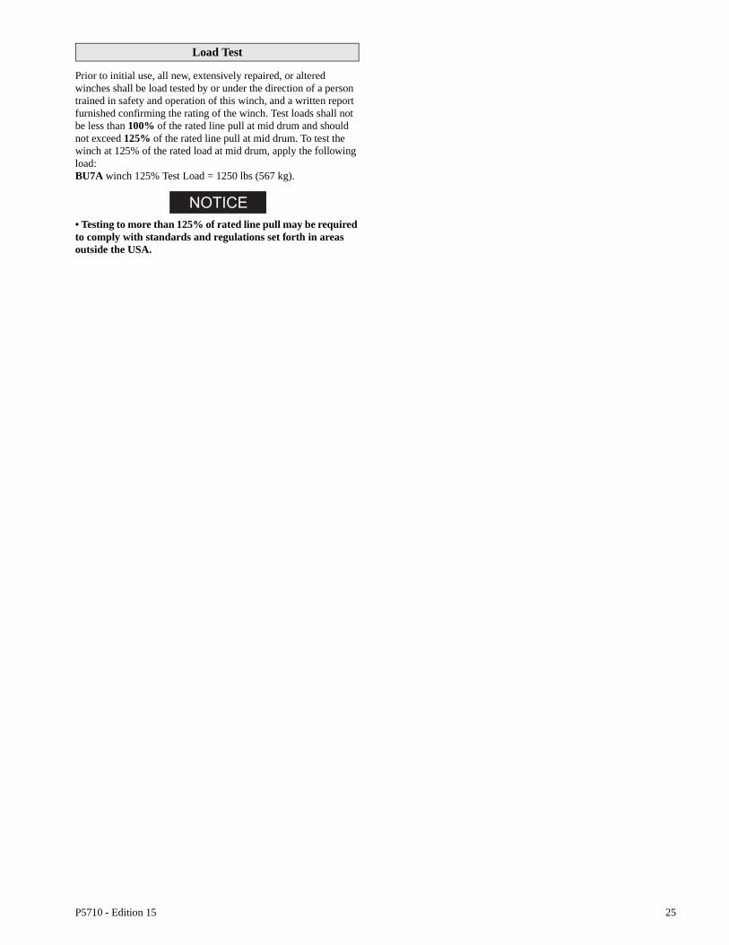
P5710 - Edition 15 25
Load Test
Prior to initial use, all new, extensively repaired, or altered winches shall be load tested by or under the direction of a person trained in safety and operation of this winch, and a written report furnished confirming the rating of the winch. Test loads shall not be less than 100% of the rated line pull at mid drum and should not exceed 125% of the rated line pull at mid drum. To test the winch at 125% of the rated load at mid drum, apply the following load:BU7A winch 125% Test Load = 1250 lbs (567 kg).
• Testing to more than 125% of rated line pull may be required to comply with standards and regulations set forth in areas outside the USA.

26 P5710 - Edition 15
WINCH ASSEMBLY PARTS DRAWING
(Dwg. MHP1207)
93
95
94
75
5
4
7298
10197
99
96
9092
86 68
898868
84
82
77
83
8491
69
71
87
78
6162
55
50
3028
31
57 56
58
59
7985
29
432
45
21
3
67
8 26
27
3025
20
11
31
3736
910
12
19
18
17
21
22
23
24
16 38
5434
35
38
39
15
14
13
102
33
67
68
66
51
53
49
48
47 7372
74
75
69
7076
7771
72
6364
65
44
52

P5710 - Edition 15 27
WINCH ASSEMBLY PARTS LIST
ItemNo.
Description Of Part
QtyTotal
PartNumber
1 Reverse Valve Nut 1 95208831
• 2 Throttle Lever 1 BU-555/556A
3 Throttle Lever Spring 1 BU-412
4 Lockwasher (pack) 17 (order 4 packs) T11-58-5
5 Screw 9 52333
6 Throttle Spring Stop Pin 1 BU-553
7 Valve Chest Cover (incl’s items 6, 13 and 102) 1 BU-K546A
• 8 ‘O’ Ring 1 410-283
9 ‘O’ Ring 1 BU-948
10 Reverse Valve Assembly (incl’s items 1, 8 and 9) 1 BU-9K44A
11 Plug 1 C6H20A-79
12Reverse Valve Bushing Kit (incl’s Loctite® 609)
1BU7A-K945
(Model BU7APTAB only) BU7ARC-945
13 Rotary Valve Thrust Washer 1 BU-552A
14 Rotary Valve Bushing Kit (incl’s Loctite® 609) 1 BU7A-K525
15 Rotary Valve 1 BU-526
• 16 Piston Ring Kit 8 D01-337-8
17 Piston Assembly (incl’s item 16) 4 D01-A513B
18 Piston Wrist Pin 4 TC-389B
19 Cylinder Sleeve 4 D01-L505A
20 Inlet Bushing 1 71386262
21 Capscrew 16 50156
22 Washer (Copper) 16 D01-504
23 Cylinder Head 4 D01-H505A
• 24 Cylinder Gasket 4 D01-507
25 Vent Cap Assembly (incl’s items 26 and 27) 1 DLC-303
26 Vent Cap Chain 1 D02-891
27 ‘S’ Hook 1 D02-421
28Motor Case Assembly (incl’s items 12, 14, 20, 30 and 31)
1BU-501A
Motor Case Assembly (BU7APTAB only)(incl’s items 14, 20, 30, 31 and 218)
BU7ARC-501
29 Capscrew 8 71126908
30 Bushing Key 2 D01-527A
31 Oil Plug 2 D02-402
• 32 Gasket 1 BU-592
33 Oil Wall 1 BU-500
34 Lockwasher 4 F-58
35 Screw 4 J-376
36 Crank Pin Sleeve 1 BU-519
37 Bushing 1 D01-511A
38 Ring 2 D01-510
39 Connecting Rod 4 D01-509A
44 Crank Assembly (incl’s items 43, 45 and 46) 1 BU7A-A516A
• Recommended Spare

28 P5710 - Edition 15
WINCH ASSEMBLY PARTS LIST (CONT’D)
Item No.
DescriptionOf Part
QtyTotal
PartNumber
47 Clutch Eccentric Shaft (Manual brake models only) 1 BU-857A
• 48 ‘O’ Ring 1 PS3-67
49Bushing
1BU-964
Bushing (Model BU7APTAB only) BU7A-728
50 Brake Lever Screw 2 51014
• 51 Clutch Lever Spring (Manual brake models only) 1 H02-81C
52 Clutch Lever Washer (Manual brake models only) 1 BU-962
53 Clutch Lever Pin (Manual brake models only) 1 BU-870A
54 Clutch Lever (Manual brake models only) 1 BU-556B
• 55 Brake Lever (incl’s items 50 and 56)(Manual brake) 1 BU-151A
• 56 Brake Trunnion 1 BU-159
57 Brake Adjusting Screw (incl’s items 58 and 59) 1 BU-K158A
58 Retainer 1 71307276
59 Brake Band Pin 1 BU-147A
• 61 Brake Band Assembly 1 BU-A152
62 Drum Shaft Assembly (incl’s item 63) 1 BU7A-A459
63 Motor Pinion Bearing 1 R2H-606
64 Drum Thrust Sleeve 1 BU-468
65 Drum Seal 1 BU7A-137
66 Gear Case Assembly (incl’s items 64, 65, 67, 68 and 73) 1 BU7A-A353
67 Nameplate 1 BU-301-R
68 Rivet 12 71028849
69Capscrew 8
54662Capscrew (Model BU7APTAB only) 6
70 Intermediate Gear 1 BU-364
71 Lockwasher 8 50181
72 Bearing 3 TB-394
73 Dowel 1 D10-527
• 74 Gasket 1 BU-931
75 Grease Plug 2 T1SE-368-3/8
76 Gear Case Cover (incl’s item 75) 1 BU-352
77 Setscrew 1 R3SM-574
78 Crank Bearing 1 58-96
79 Motor Mount Bracket 1 BU-502
82 Grease Seal 1 BU-866
83 Thrust Plate 1 BU-469
84 Bearing 2 BU-466
85 Setscrew 2 BU-381
86 Drum Assembly (incl’s items 82 through 85) 1 BU7A-A324
87 Base (incl’s items 68, 88 through 90) 1 BU-564A
* Warning Tag 1 71056410
* Illustrated on Page 4
• Recommended Spare
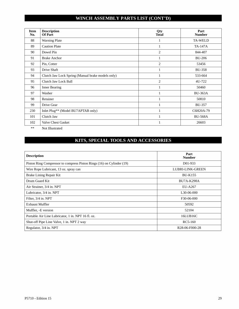
P5710 - Edition 15 29
WINCH ASSEMBLY PARTS LIST (CONT’D)
KITS, SPECIAL TOOLS AND ACCESSORIES
ItemNo.
DescriptionOf Part
QtyTotal
PartNumber
88 Warning Plate 1 TA-WELD
89 Caution Plate 1 TA-147A
90 Dowel Pin 2 844-407
91 Brake Anchor 1 BU-206
92 Pin, Cotter 2 53456
93 Drive Shaft 1 BU-358
94 Clutch Jaw Lock Spring (Manual brake models only) 1 533-664
95 Clutch Jaw Lock Ball 2 4U-722
96 Inner Bearing 1 50460
97 Washer 1 BU-363A
98 Retainer 1 50810
99 Drive Gear 1 BU-357
230 Inlet Plug** (Model BU7APTAB only) 1 C6H20A-79
101 Clutch Jaw 1 BU-568A
102 Valve Chest Gasket 1 26603
** Not Illustrated
Description PartNumber
Piston Ring Compressor to compress Piston Rings (16) on Cylinder (19) D01-933
Wire Rope Lubricant, 13 oz. spray can LUBRI-LINK-GREEN
Brake Lining Repair Kit BU-K155
Drum Guard Kit BU7A-K298A
Air Strainer, 3/4 in. NPT EU-A267
Lubricator, 3/4 in. NPT L30-06-000
Filter, 3/4 in. NPT F30-06-000
Exhaust Muffler 50592
Muffler, -E version 52104
Portable Air Line Lubricator, 1 in. NPT 16 fl. oz. 16LUB16C
Shut-off Pipe Line Valve, 1 in. NPT 2 way RC5-160
Regulator, 3/4 in. NPT R28-06-F000-28

30 P5710 - Edition 15
AUTOMATIC BRAKE ASSEMBLY DRAWING
(Dwg. MHP1210)
71
1 4 1101
7 2
35
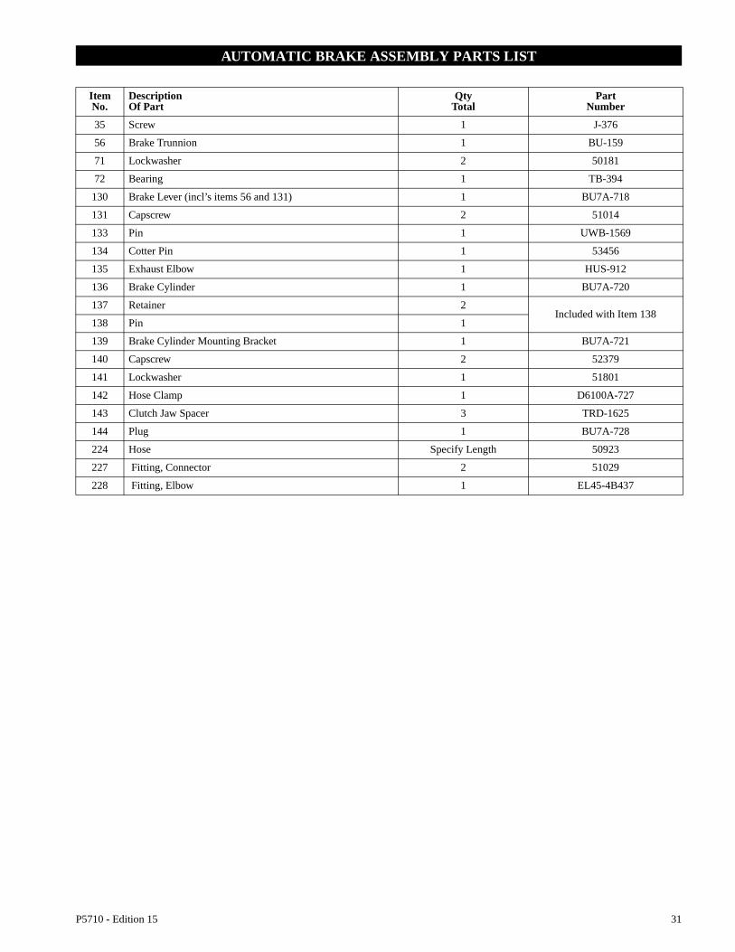
P5710 - Edition 15 31
AUTOMATIC BRAKE ASSEMBLY PARTS LIST
Item No.
DescriptionOf Part
QtyTotal
PartNumber
35 Screw 1 J-376
56 Brake Trunnion 1 BU-159
71 Lockwasher 2 50181
72 Bearing 1 TB-394
130 Brake Lever (incl’s items 56 and 131) 1 BU7A-718
131 Capscrew 2 51014
133 Pin 1 UWB-1569
134 Cotter Pin 1 53456
135 Exhaust Elbow 1 HUS-912
136 Brake Cylinder 1 BU7A-720
137 Retainer 2Included with Item 138
138 Pin 1
139 Brake Cylinder Mounting Bracket 1 BU7A-721
140 Capscrew 2 52379
141 Lockwasher 1 51801
142 Hose Clamp 1 D6100A-727
143 Clutch Jaw Spacer 3 TRD-1625
144 Plug 1 BU7A-728
224 Hose Specify Length 50923
227 Fitting, Connector 2 51029
228 Fitting, Elbow 1 EL45-4B437
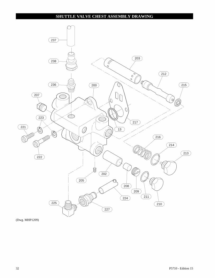
32 P5710 - Edition 15
SHUTTLE VALVE CHEST ASSEMBLY DRAWING
(Dwg. MHP1209)
225
227
224 211
209
208
202
205
222
221
223
13
217
207
236 200
238
237
203
212
215
216
214
213
210
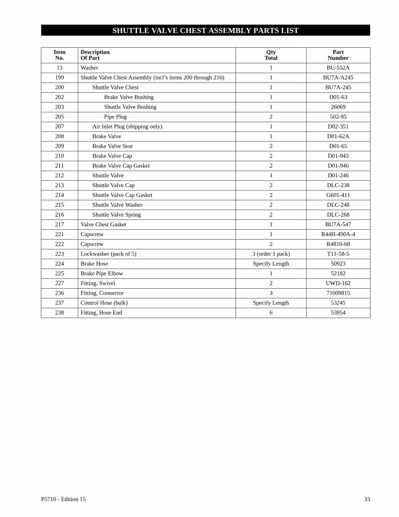
P5710 - Edition 15 33
SHUTTLE VALVE CHEST ASSEMBLY PARTS LIST
ItemNo.
DescriptionOf Part
QtyTotal
PartNumber
13 Washer 1 BU-552A
199 Shuttle Valve Chest Assembly (incl’s items 200 through 216) 1 BU7A-A245
200 Shuttle Valve Chest 1 BU7A-245
202 Brake Valve Bushing 1 D01-63
203 Shuttle Valve Bushing 1 26069
205 Pipe Plug 2 502-95
207 Air Inlet Plug (shipping only) 1 D02-351
208 Brake Valve 1 D01-62A
209 Brake Valve Seat 2 D01-65
210 Brake Valve Cap 2 D01-943
211 Brake Valve Cap Gasket 2 D01-946
212 Shuttle Valve 1 D01-246
213 Shuttle Valve Cap 2 DLC-238
214 Shuttle Valve Cap Gasket 2 G601-411
215 Shuttle Valve Washer 2 DLC-248
216 Shuttle Valve Spring 2 DLC-268
217 Valve Chest Gasket 1 BU7A-547
221 Capscrew 1 R44H-490A-4
222 Capscrew 2 R4810-68
223 Lockwasher (pack of 5) 3 (order 1 pack) T11-58-5
224 Brake Hose Specify Length 50923
225 Brake Pipe Elbow 1 52182
227 Fitting, Swivel 2 UWD-162
236 Fitting, Connector 3 71009815
237 Control Hose (bulk) Specify Length 53245
238 Fitting, Hose End 6 53954

34 P5710 - Edition 15
REMOTE CONTROL VALVE ASSEMBLY PARTS DRAWING
(Dwg. MHP2221)
Use Loctite 609Ref. MHD56154for Installationprocedures.
199199199
13217
218
238
236
160
237

P5710 - Edition 15 35
REMOTE CONTROL VALVE ASSEMBLY PARTS LIST
DRUM GUARD ASSEMBLY DRAWING AND PARTS LIST
(Dwg. MHP1213)
ItemNo.
DescriptionOf Part
QtyTotal
PartNumber
13 Washer 1 BU-552A
160 Pendant Assembly (refer to Dwg. MHP1072 on page 38) 1 MR-269C
199 Shuttle Valve Chest Assembly 1 BU7A-A245
217 Valve Chest Gasket 1 BU7A-547
218 Ported Plug 1 BU7ARC-945
236 Fitting, Connector 3 71009815
237 Hose (bulk) As Req’d 53245
238 Fitting, Hose End 3 53954
Item No.
DescriptionOf Part
QtyTotal
PartNumber
300 Drum Guard Assy. 1 BU7A-K298A
301 Drum Guard 1 order item 300
302 Capscrew 2 71329833
303 Nut 2 50171
Note: Remove the minimum amount of mesh from the drumguard to provide clearance for wire rope departure.

36 P5710 - Edition 15
E-STOP VALVE AND MUFFLER ASSEMBLY DRAWINGS
(Dwg. MHP2222)
250
243
244
240
240

P5710 - Edition 15 37
E-STOP VALVE AND MUFFLER ASSEMBLY PARTS LISTS
ItemNo.
DescriptionOf Part
QtyTotal
PartNumber
240 Muffler 1 52104
241 Fitting, Adapter 1 71386924
243 Fitting, Nipple 1 AAM-287
244 Stop Valve 1 76170017
250 Fitting, Elbow Reducer 1 71386916

38 P5710 - Edition 15
REMOTE PENDANT THROTTLE HANDLE DRAWING AND PARTS LIST
(Dwg. MHP1072)
236
YellowPayout
RedSupply
GreenHaul-in
Haul-in
Payout
171167168
169
160
176
175
173
172
166
ItemNo.
DescriptionOf Part
QtyTotal
PartNumber
160 Pendant Assembly (incl’s all items below) 1 MR-269C
166 Throttle Lever 2 MR-273
167 Throttle Lever Pin 1 DLC-120A
168 Screw 3 MLK-SR662
169 Lockwasher 3 D02-138
171 Bushing 2 D02-263A
172 Throttle Valve 2 MR-264
• 173 Throttle Valve Seal Ring 4 AF120-289
• 175 Throttle Valve Spring 2 D01-51A
176 Valve Cap 2 D02-180A
236 Fitting, Connector 3 71009815
237 Hose* (bulk) Specify Length 53245
238 Fitting, Hose End* 6 53954
* Refer to Dwg. MHP1209 on page 32.
• Recommended Spare

P5710 - Edition 15 39
LABEL LOCATIONS DRAWING AND PARTS LIST
(Dwg. MHP2223)
246
245
67
88
247
248
89
P/N
961
8010
2
P/N 9618 0099
Ingersoll-Rand Co. 2724 6th Ave. So.Seattle, WA 98134
Ingersoll-Rand Co. 111, avenue Roger Salengro,59450 Sin Le Nobel, France
71153852
P/N
9618
010
3
ItemNo.
DescriptionOf Part
QtyTotal
Part Number
Standard -E Version
67 Nameplate (illustrated on page 42) 1 BU-301-R
88 Warning Plate (illustrated on page 4) 1 TA-WELD
89 Caution Plate (illustrated on page 4) 1 TA-147A
245 Label, Overwind Cable 1 - - - 96180103
246 Label, Control Valve Operation 1 - - - 96180102
247 Label, No Lift 1 - - - 96180099
248 Label, CE 1 - - - 71153852
* Warning Tag 1 71056410 - - -
*Illustrated on page 4

40 P5710 - Edition 15
CONSTRUCTION CAGE DRAWING AND PARTS LIST
(Dwg. MHP2279)
3
311
310
12
313314
315316
317
318
319
320
321
ItemNo.
DescriptionOf Part
QtyTotal
PartNumber
310 Cage 1 27398G
311 Capscrew 4 51876
312 Washer 4 71064844
313 Lockwasher 4 50181
314 Nut 4 50171
315 Label, Specifications 1 71359210
316 Plexiglass Cover 1 27427
317 Screw 4 50851
318 Nut 4 50852
319 Label, Warning 1 71359160
320 Nameplate 1 71359392
321 Rivet 4 71028849
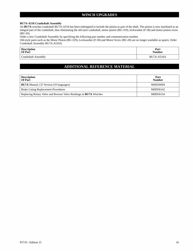
P5710 - Edition 15 41
WINCH UPGRADES
BU7A-A516 Crankshaft AssemblyOn BU7A winches crankshaft BU7A-A516 has been redesigned to include the pinion as part of the shaft. The pinion is now machined as an integral part of the crankshaft, thus eliminating the old style crankshaft, motor pinion (BU-319), lockwasher (F-58) and motor pinion screw (BU-20).Order a new Crankshaft Assembly by specifying the following part number and communication number.Old-style parts such as the Motor Pinion (BU-319), Lockwasher (F-58) and Motor Screw (BU-20) are no longer available as spares. Order Crankshaft Assembly BU7A-A516A.
ADDITIONAL REFERENCE MATERIAL
DescriptionOf Part
PartNumber
Crankshaft Assembly BU7A-A516A
DescriptionOf Part
PartNumber
BU7A Manual, CE Version (10 languages) MHD56094
Brake Lining Replacement Procedures MHD56142
Replacing Rotary Valve and Reverse Valve Bushings in BU7A Winches MHD56154

42 P5710 - Edition 15
PARTS ORDERING INFORMATION
The BU7A winch is designed and constructed to provide long, trouble-free service. In time it may become necessary to order and install new parts to replace those that have been subjected to wear.
The use of other than Ingersoll-Rand replacement parts may result in decreased winch performance, and may, at the company’s option, invalidate the warranty. For prompt service and genuine Ingersoll-Rand replacement parts, provide your nearest Distributor with the following:1. Complete model number and serial number as it appears on
the nameplate.2. Part number(s) and part description as shown in this manual. 3. Quantity required.
The model and serial number plate is located on the gear case housing at the clutch end.
For your convenience and future reference, it is recommended that the following information be recorded:
Model Number _______________________________________
Serial Number ________________________________________
Date Purchased _______________________________________
• Continuing improvement and advancement of design may cause changes to this equipment which are not included in this manual. Manuals are periodically revised to incorporate changes. Always check the manual edition number on the front cover for the latest issue. Sections of this manual may not apply to your winch.
Return Goods Policy
Ingersoll-Rand will not accept any returned goods for warranty or service work unless prior arrangements have been made and written authorization has been provided from the location where the goods were purchased. Winches which have been modified without Ingersoll-Rand approval, mishandled or overloaded will not be repaired or replaced under warranty. A printed copy of the warranty which applies to this winch is provided inside the back cover of this manual.
Disposal
When the life of the unit has expired, it is recommended that the it be disassembled, degreased and parts separated as to materials so that they may be recycled.
For additional information contact:
Ingersoll-RandP.O. Box 240462724 Sixth Avenue SouthSeattle, WA 98124-0046 USAPhone: (206) 624-0466Fax: (206) 624-6265
or
Ingersoll-RandDouai Operations111, Avenue Roger Salengro59450 Sin Le Noble, FrancePhone: (33) 03-27-93-08-08Fax: (33) 03-27-93-08-00
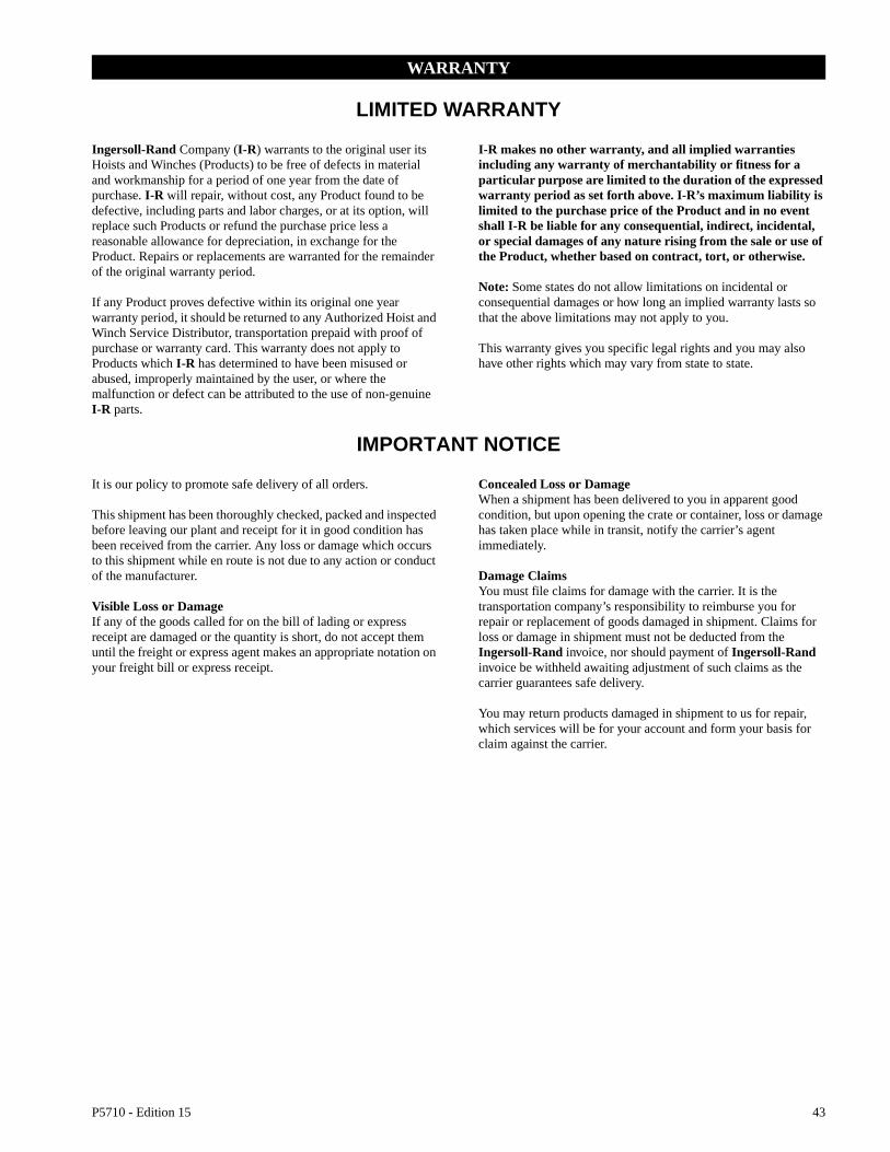
P5710 - Edition 15 43
WARRANTY
LIMITED WARRANTY
Ingersoll-Rand Company (I-R) warrants to the original user its Hoists and Winches (Products) to be free of defects in material and workmanship for a period of one year from the date of purchase. I-R will repair, without cost, any Product found to be defective, including parts and labor charges, or at its option, will replace such Products or refund the purchase price less a reasonable allowance for depreciation, in exchange for the Product. Repairs or replacements are warranted for the remainder of the original warranty period.
If any Product proves defective within its original one year warranty period, it should be returned to any Authorized Hoist and Winch Service Distributor, transportation prepaid with proof of purchase or warranty card. This warranty does not apply to Products which I-R has determined to have been misused or abused, improperly maintained by the user, or where the malfunction or defect can be attributed to the use of non-genuine I-R parts.
I-R makes no other warranty, and all implied warranties including any warranty of merchantability or fitness for a particular purpose are limited to the duration of the expressed warranty period as set forth above. I-R’s maximum liability is limited to the purchase price of the Product and in no event shall I-R be liable for any consequential, indirect, incidental, or special damages of any nature rising from the sale or use of the Product, whether based on contract, tort, or otherwise.
Note: Some states do not allow limitations on incidental or consequential damages or how long an implied warranty lasts so that the above limitations may not apply to you.
This warranty gives you specific legal rights and you may also have other rights which may vary from state to state.
IMPORTANT NOTICE
It is our policy to promote safe delivery of all orders.
This shipment has been thoroughly checked, packed and inspected before leaving our plant and receipt for it in good condition has been received from the carrier. Any loss or damage which occurs to this shipment while en route is not due to any action or conduct of the manufacturer.
Visible Loss or DamageIf any of the goods called for on the bill of lading or express receipt are damaged or the quantity is short, do not accept them until the freight or express agent makes an appropriate notation on your freight bill or express receipt.
Concealed Loss or DamageWhen a shipment has been delivered to you in apparent good condition, but upon opening the crate or container, loss or damage has taken place while in transit, notify the carrier’s agent immediately.
Damage ClaimsYou must file claims for damage with the carrier. It is the transportation company’s responsibility to reimburse you for repair or replacement of goods damaged in shipment. Claims for loss or damage in shipment must not be deducted from the Ingersoll-Rand invoice, nor should payment of Ingersoll-Rand invoice be withheld awaiting adjustment of such claims as the carrier guarantees safe delivery.
You may return products damaged in shipment to us for repair, which services will be for your account and form your basis for claim against the carrier.

Printed in USA
United States Office Locations International Office Locations
For Order Entry and Order Status
Ingersoll-RandDistribution CenterP.O. Box 618510 Hester DriveWhite House, TN 37188Phone: (615) 672-0321Fax: (615) 672-0801
For Technical Support
Ingersoll-RandP.O. Box 240462724 Sixth Avenue SouthSeattle, WA 98124-0046Phone: (206) 624-0466Fax: (206) 624-6265
Web Site:www.irco.com
Regional Sales Offices
Chicago, IL131 W. Diversey AvenueElmhurst, IL 60126-1102Phone: (630) 530-3800Fax: (630) 530-3891
Detroit, MI1872 Enterprise DriveRochester, MI 48309Phone: (248) 293-5700Fax: (248) 293-5800
Houston, TX450 Gears RoadSuite 210Houston, TX 77067-4516Phone: (281) 872-6800Fax: (281) 872-6807
Los Angeles, CA13107 Lakeland RoadSanta Fe Springs, CA 90670-0525Phone: (562) 777-0808Fax: (562) 777-0818
Philadelphia, PAP.O. Box 425900 E. 8th Ave., Suite 103King of Prussia, PA 19406Phone: (610) 337-5930Fax: (610) 337-5912
Offices and distributors in principal cities throughout the world. Contact the nearest Ingersoll-Rand office for the name and address of the distributor in your country or write/fax to:
CanadaNational Sales OfficeRegional WarehouseToronto, Ontario51 Worcester RoadRexdale, OntarioM9W 4K2Phone: (416) 213-4500Fax: (416) 213-4510Order DeskFax: (416) 213-4506
Regional Sales OfficesEdmonton, AlbertaPhone: (780) 438-5039Fax: (780) 439-7382
Montreal, Quebec3501 St. Charles Blvd.Suite 104Kirkland, QuebecH9H 4S3Phone: (514) 695-9040Fax: (514) 695-0963
British Columbia1200 Cliveden AvenueDelta, B.C.V3M 6G4Phone: (604) 523-0803Fax: (604) 523-0801
Latin America OperationsIngersoll-RandProduction Equipment Group730 N.W. 107 AvenueSuite 300, Miami, FL33172-3107Phone: (305) 559-0500Fax: (305) 222-0864
Europe, Middle East and AfricaIngersoll-RandDouai Operations111, avenue Roger Salengro59450 Sin Le Noble, FrancePhone: (33) 3-27-93-08-08Fax: (33) 3-27-93-08-00
Asia Pacific OperationsIngersoll-Rand Asia Pacific23/F., 625 King’s RoadNorth Point, Hong KongPhone: (852) 2527 0183Fax: (852) 2529 5976
RussiaIngersoll-RandKuznetsky Most 21/5Entrance 3Moscow 103895 RussiaPhone: (7) 501 923 9134Fax: (7) 501 924 4625
AustraliaIngersoll-Rand Aust1 Hartnett DriveSeaford, Vic 3198AustraliaPhone: 613 95541642Fax: 613 95541607