Embed Size (px)
Citation preview
Printed in U.S.A.
Parts Catalog
OTPC 150/225/260 AmpTransfer Switch
962–0228B (Spec A) 5-2001
The following symbols are used in Cummins PowerGeneration manuals to alert users to the potentiallydangerous conditions relating to maintenance ofequipment and replacement of parts. Please readand observe.
This symbol warns of immediatehazards which will result in severepersonal injury or death.
This symbol refers to a hazard orunsafe practice which can resultin severe personal injury or death.
This symbol refers to a hazard orunsafe practice which can resultin severe personal injury or prod-uct or property damage.
This catalog covers models produced under theCummins /Onan and Cummins Power Genera-tion brand names.
To avoid errors or delay in filling your parts order, al-ways give the MODEL, SPEC NO. and SERIAL NO.from the Cummins Power Generation nameplate.
For handy reference, insert your nameplate in-formation in the spaces below.
MODEL AND SPEC NO.
SERIAL NO.
DIGITAL CONTROL SOFTWARE VERSIONAND DATE (IF APPLICABLE)
Contact with USED ENGINE OILS has been identified by a United States federal agency and some USAstate agencies as causing CANCER or REPRODUCTIVE TOXICITY. When checking or changing engineoils take all necessary precautions not to ingest, breathe the fumes or contact the used oil.
Contact with ASBESTOS has been identified by a United States federal agency and some USA state agen-cies as causing CANCER or REPRODUCTIVE TOXICITY. When handling engine gaskets take all neces-sary precautions not to ingest, breathe or contact the dust from the gaskets! Use adequate ventilationand wear protective gloves, masks and clothing!
Contact with BENZINE and LEAD, found in gasoline, fuel additives and solvents has been identified bya United States federal agency and some USA state agencies as causing CANCER or REPRODUCTIVETOXICITY. When checking, draining or adding gasoline and fuel additives or using solvents take all nec-essary precautions not to ingest, breathe the fumes or contact the liquids. Use adequate ventilation andwear protective gloves, masks and protective clothing!
PSP-1
Service and repair of Cummins Power Generation equipment must be performed by trained, experiencedpersonnel only. Improper service or repair may result in property damage, severe personal injury ordeath. Do not use this catalog as a guide to servicing your equipment. Read and follow the IMPORTANTSAFETY INSTRUCTIONS in the Service Manual appropriate for the equipment you are working on.
1
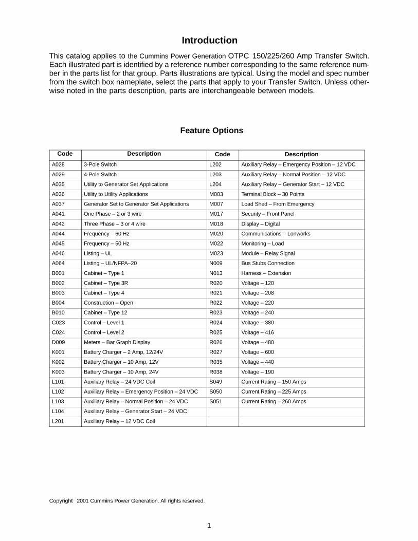
Introduction
This catalog applies to the Cummins Power Generation OTPC 150/225/260 Amp Transfer Switch.Each illustrated part is identified by a reference number corresponding to the same reference num-ber in the parts list for that group. Parts illustrations are typical. Using the model and spec numberfrom the switch box nameplate, select the parts that apply to your Transfer Switch. Unless other-wise noted in the parts description, parts are interchangeable between models.
Feature Options
Code Description Code Description
A028 3-Pole Switch L202 Auxiliary Relay – Emergency Position – 12 VDC
A029 4-Pole Switch L203 Auxiliary Relay – Normal Position – 12 VDC
A035 Utility to Generator Set Applications L204 Auxiliary Relay – Generator Start – 12 VDC
A036 Utility to Utility Applications M003 Terminal Block – 30 Points
A037 Generator Set to Generator Set Applications M007 Load Shed – From Emergency
A041 One Phase – 2 or 3 wire M017 Security – Front Panel
A042 Three Phase – 3 or 4 wire M018 Display – Digital
A044 Frequency – 60 Hz M020 Communications – Lonworks
A045 Frequency – 50 Hz M022 Monitoring – Load
A046 Listing – UL M023 Module – Relay Signal
A064 Listing – UL/NFPA–20 N009 Bus Stubs Connection
B001 Cabinet – Type 1 N013 Harness – Extension
B002 Cabinet – Type 3R R020 Voltage – 120
B003 Cabinet – Type 4 R021 Voltage – 208
B004 Construction – Open R022 Voltage – 220
B010 Cabinet – Type 12 R023 Voltage – 240
C023 Control – Level 1 R024 Voltage – 380
C024 Control – Level 2 R025 Voltage – 416
D009 Meters – Bar Graph Display R026 Voltage – 480
K001 Battery Charger – 2 Amp, 12/24V R027 Voltage – 600
K002 Battery Charger – 10 Amp, 12V R035 Voltage – 440
K003 Battery Charger – 10 Amp, 24V R038 Voltage – 190
L101 Auxiliary Relay – 24 VDC Coil S049 Current Rating – 150 Amps
L102 Auxiliary Relay – Emergency Position – 24 VDC S050 Current Rating – 225 Amps
L103 Auxiliary Relay – Normal Position – 24 VDC S051 Current Rating – 260 Amps
L104 Auxiliary Relay – Generator Start – 24 VDC
L201 Auxiliary Relay – 12 VDC Coil
Copyright� 2001 Cummins Power Generation. All rights reserved.

Index
2
Actuator, Linear – Transfer Switch, 9Alarm, Battery Charger, 22Ammeter – DC – 10 Amp, 12 Volt Battery Charger, 25Ammeter – DC – 10 Amp, 24 Volt Battery Charger, 27Ammeter – DC – 2 Amp, 12/24 Volt Battery Charger, 23Arm, Interlock – Transfer Switch, 9
Bar, Interlock – Transfer Switch, 9Bar, Neutral – Transfer Switch, 9Barrier – Transfer Switch, 7Barrier, Base – Transfer Switch, 9Base, Mounting – Transfer Switch, 7Block and Contact Assembly – Transfer Switch, 9Block and Cross Bar Assembly – Transfer Switch, 9Block, Hinge – Type 1 Cabinet, 13Block, Lug Mounting – Transfer Switch, 9Block, Terminal, 30Block, Terminal – Battery Charger Alarm, 22Block, Terminal – Network Module, 28Block, Terminal – Transfer Switch, 7Board, Printed Circuit – 10 Amp, 12 Volt Battery Charger, 25Board, Printed Circuit – 10 Amp, 24 Volt Battery Charger, 27Board, Printed Circuit – 2 Amp, 12/24 Volt Battery Charger,
23Board, Printed Circuit – Bar Graph – Type 1 Cabinet, 13Board, Printed Circuit – Bar Graph – Type 3R and 12
Cabinet, 15Board, Printed Circuit – Bar Graph – Type 4 Cabinet, 17Board, Printed Circuit – Current Transformer Module, 29Board, Printed Circuit – Digital – Type 1 Cabinet, 13Board, Printed Circuit – Digital – Type 3R and 12 Cabinet,
15Board, Printed Circuit – Digital – Type 4 Cabinet, 17Board, Printed Circuit – Network Module, 28Board, Printed Circuit – Power Module – Type 1 Cabinet, 13Board, Printed Circuit – Power Module – Type 3R and 12
Cabinet, 15Board, Printed Circuit – Power Module – Type 4 Cabinet, 17Board, Printed Circuit – Relay Module, 32Bracket, Connector – Accessory Control Plate (600 Volt), 19Bracket, Connector – Accessory Control Plate (Less than
600 Volt), 18Bracket, Door – Type 4 Cabinet, 17Bracket, End – Auxiliary Relay, 31Bracket, End – Terminal – Battery Charger Alarm, 22Bracket, End – Terminal – Network Module, 28Bracket, Terminal – Transfer Switch, 7Breaker, Circuit – Transfer Switch, 9Bus, Emergency – Transfer Switch, 9Bus, Load – Transfer Switch, 9Bus, Normal – Transfer Switch, 9
Cabinet – Type 1, 13Cabinet – Type 12, 15Cabinet – Type 3R, 15Cabinet – Type 4, 17Capacitor – Transfer Switch, 9Charger, Battery – 10 Amp, 12 Volt, 25Charger, Battery – 10 Amp, 24 Volt, 27Charger, Battery – 2 Amp, 12/24 Volt, 23Chute, Arc – Transfer Switch, 9Cover, Arc Chute – Transfer Switch, 9
Cover, Charger – 10 Amp, 12 Volt Battery Charger, 25Cover, Charger – 10 Amp, 24 Volt Battery Charger, 27Cover, Charger – 2 Amp, 12/24 Volt Battery Charger, 23Cover, Labeled – Transfer Switch, 7Cover, Printed Circuit Board – Type 1 Cabinet, 13Cover, Printed Circuit Board – Type 3R and 12 Cabinet, 15Cover, Printed Circuit Board – Type 4 Cabinet, 17Cover, Relay Plate – Accessory Control Plate (600 Volt), 19Cover, Relay Plate – Accessory Control Plate (Less than
600 Volt), 18
Door, Cabinet – Type 1, 13Door, Cabinet – Type 3R and 12 Cabinet, 15Door, Cabinet – Type 4 Cabinet, 17
Fuse – 10 Amp, 12 Volt Battery Charger, 25Fuse – 10 Amp, 24 Volt Battery Charger, 27Fuse – 2 Amp, 12/24 Volt Battery Charger, 23
Gasket, Door – Type 3R and 12 Cabinet, 15Gasket, Door – Type 4 Cabinet, 17
Handle Assembly, Actuator, 10Handle, Door – Type 3R and 12 Cabinet, 15Handle, Locking – Type 1 Cabinet, 13Harness, Wiring – 10 Amp, 12 Volt Battery Charger, 25Harness, Wiring – 10 Amp, 24 Volt Battery Charger, 27Harness, Wiring – 2 Amp, 12/24 Volt Battery Charger, 23Harness, Wiring – Battery Charger, 21Harness, Wiring – Battery Charger Alarm, 22Harness, Wiring – Control – Open Construction, 20Harness, Wiring – Current Transformer Module, 29Harness, Wiring – Load Shed, 32Harness, Wiring – Main – Type 1 Cabinet, 13Harness, Wiring – Main – Type 3R and 12 Cabinet, 15Harness, Wiring – Main – Type 4 Cabinet, 17Harness, Wiring – Network Module, 28Holder, Fuse – 10 Amp, 12 Volt Battery Charger, 25Holder, Fuse – 10 Amp, 24 Volt Battery Charger, 27Holder, Fuse – 2 Amp, 12/24 Volt Battery Charger, 23
Insulator, Arc Chute – Transfer Switch, 9
Latch, Cam – Type 1 Cabinet, 13Latch, Cam – Type 3R and 12 Cabinet, 15Lead – Type 1 Cabinet, 13Lead – Type 3R and 12 Cabinet, 15Lead – Type 4 Cabinet, 17Load Shed, 32Lug, Solderless – Transfer Switch, 9Lug, Solderless – Type 1 Cabinet, 13Lug, Solderless – Type 3R and 12 Cabinet, 15Lug, Solderless – Type 4 Cabinet, 17
Membrane, Panel – Type 1 Cabinet, 13Membrane, Panel – Type 3R and 12 Cabinet, 15Membrane, Panel – Type 4 Cabinet, 17Module, Current Transformer, 29Module, Digital Display – Type 1 Cabinet, 13Module, Digital Display – Type 3R and 12 Cabinet, 15Module, Digital Display – Type 4 Cabinet, 17Module, Network, 28
Index
3
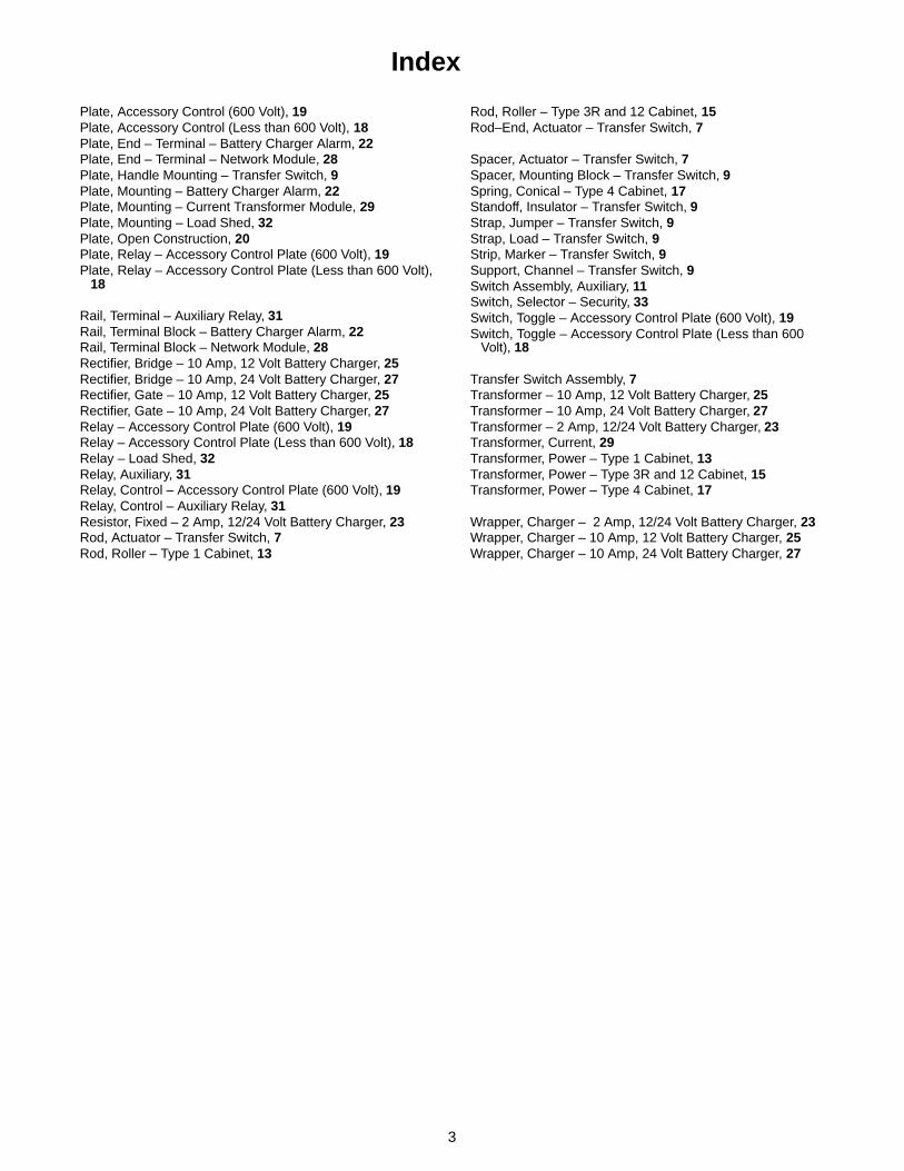
Plate, Accessory Control (600 Volt), 19Plate, Accessory Control (Less than 600 Volt), 18Plate, End – Terminal – Battery Charger Alarm, 22Plate, End – Terminal – Network Module, 28Plate, Handle Mounting – Transfer Switch, 9Plate, Mounting – Battery Charger Alarm, 22Plate, Mounting – Current Transformer Module, 29Plate, Mounting – Load Shed, 32Plate, Open Construction, 20Plate, Relay – Accessory Control Plate (600 Volt), 19Plate, Relay – Accessory Control Plate (Less than 600 Volt),
18
Rail, Terminal – Auxiliary Relay, 31Rail, Terminal Block – Battery Charger Alarm, 22Rail, Terminal Block – Network Module, 28Rectifier, Bridge – 10 Amp, 12 Volt Battery Charger, 25Rectifier, Bridge – 10 Amp, 24 Volt Battery Charger, 27Rectifier, Gate – 10 Amp, 12 Volt Battery Charger, 25Rectifier, Gate – 10 Amp, 24 Volt Battery Charger, 27Relay – Accessory Control Plate (600 Volt), 19Relay – Accessory Control Plate (Less than 600 Volt), 18Relay – Load Shed, 32Relay, Auxiliary, 31Relay, Control – Accessory Control Plate (600 Volt), 19Relay, Control – Auxiliary Relay, 31Resistor, Fixed – 2 Amp, 12/24 Volt Battery Charger, 23Rod, Actuator – Transfer Switch, 7Rod, Roller – Type 1 Cabinet, 13
Rod, Roller – Type 3R and 12 Cabinet, 15Rod–End, Actuator – Transfer Switch, 7
Spacer, Actuator – Transfer Switch, 7Spacer, Mounting Block – Transfer Switch, 9Spring, Conical – Type 4 Cabinet, 17Standoff, Insulator – Transfer Switch, 9Strap, Jumper – Transfer Switch, 9Strap, Load – Transfer Switch, 9Strip, Marker – Transfer Switch, 9Support, Channel – Transfer Switch, 9Switch Assembly, Auxiliary, 11Switch, Selector – Security, 33Switch, Toggle – Accessory Control Plate (600 Volt), 19Switch, Toggle – Accessory Control Plate (Less than 600
Volt), 18
Transfer Switch Assembly, 7Transformer – 10 Amp, 12 Volt Battery Charger, 25Transformer – 10 Amp, 24 Volt Battery Charger, 27Transformer – 2 Amp, 12/24 Volt Battery Charger, 23Transformer, Current, 29Transformer, Power – Type 1 Cabinet, 13Transformer, Power – Type 3R and 12 Cabinet, 15Transformer, Power – Type 4 Cabinet, 17
Wrapper, Charger – 2 Amp, 12/24 Volt Battery Charger, 23Wrapper, Charger – 10 Amp, 12 Volt Battery Charger, 25Wrapper, Charger – 10 Amp, 24 Volt Battery Charger, 27

4
Abbreviations
Some of the following abbreviations may be used throughout this Parts Catalog:
AC Alternating CurrentAmp AmpereA/R As RequiredAVR Automatic Voltage RegulatorAWG American Wire GaugeCSA Canadian Standard
AssociationDC Direct CurrentDeg. DegreeEFC Electronic Fuel ControlEIT External/Internal ToothEPROM Erasable Programmable
Read Only MemoryET External ToothGFI Ground Fault InterrupterID Inside DiameterIEC International Electrotechnical CommissionIT Internal ToothkW KilowattLPG Liquid Petroleum GasLT LeftM(meter number) Meter
MCM Metric Circular Milsmm MillimeterMOH Mobile Off HighwayNFS Not For SaleNPT National Pipe ThreadOD Outside Diameteroz. OuncePCB Printed Circuit BoardPh PhasePMG Permanent Magnet GeneratorPT/CT Potential Transformer/
Current TransformerRFI Radio Frequency InterferenceRT RightSpec SpecificationThk ThickUL Underwriters Laboratories Inc.UNC Union National CoarseUNF Union National FineVAC Volts Alternating CurrentVDC Volts Direct CurrentW/(ET, IT, EIT) With

5

6
Transfer Switch
1
2
3
4
4
4
45
6
7
8
9
10
8
910
9
10
11
12
12
13
14
15
15
15
15
15
15
15
1617
1816
19
20
21
22
23
25
26
27
28
29
30
3131
31
33
3334
35
36
36
37
37
38
39
40
41
42
43
44
45
46
47
48
49
50
51
52
53
54
55
56
57
58
59
61
60
62
32
63
64
64
65
24

7
Transfer Switch
REF PART QTY PART REF PART QTY PARTNO. NO. USED DESCRIPTION NO. NO. USED DESCRIPTION
Transfer Switch Assembly3-Pole, Front Connect with
Mechanical Lugs150 Amp
306–4404–01 1 120 VAC306–4404–02 1 190 VAC306–4404–03 1 208/220/240/600* VAC306–4404–04 1 380/416 VAC306–4404–05 1 440/480 VAC
225 Amp306–4404–06 1 120 VAC306–4404–07 1 190 VAC306–4404–08 1 208/220/240/600* VAC306–4404–09 1 380/416 VAC306–4404–10 1 440/480 VAC
260 Amp306–4404–11 1 120 VAC306–4404–12 1 190 VAC306–4404–13 1 208/220/240/600* VAC306–4404–14 1 380/416 VAC306–4404–15 1 440/480 VAC
4-Pole, Front Connect with Mechanical Lugs
150 Amp306–4405–02 1 190 VAC306–4405–03 1 208/220/240/600* VAC306–4405–04 1 380/416 VAC306–4405–05 1 440/480 VAC
225 Amp306–4405–07 1 190 VAC306–4405–08 1 208/220/240/600* VAC306–4405–09 1 380/416 VAC306–4405–10 1 440/480 VAC
260 Amp306–4405–12 1 190 VAC306–4405–13 1 208/220/240/600* VAC306–4405–14 1 380/416 VAC306–4405–15 1 440/480 VAC
3-Pole, Rear Connect with Bus Stubs
150 Amp306–4406–01 1 120 VAC306–4406–02 1 190 VAC306–4406–03 1 208/220/240/600* VAC306–4406–04 1 380/416 VAC306–4406–05 1 440/480 VAC
225 Amp306–4406–06 1 120 VAC306–4406–07 1 190 VAC306–4406–08 1 208/220/240/600* VAC306–4406–09 1 380/416 VAC306–4406–10 1 440/480 VAC
260 Amp306–4406–11 1 120 VAC306–4406–12 1 190 VAC306–4406–13 1 208/220/240/600* VAC306–4406–14 1 380/416 VAC306–4406–15 1 440/480 VAC
4-Pole, Rear Connect with Bus Stubs
150 Amp306–4407–02 1 190 VAC306–4407–03 1 208/220/240/600* VAC306–4407–04 1 380/416 VAC306–4407–05 1 440/480 VAC
225 Amp306–4407–07 1 190 VAC306–4407–08 1 208/220/240/600* VAC306–4407–09 1 380/416 VAC306–4407–10 1 440/480 VAC
260 Amp306–4407–12 1 190 VAC306–4407–13 1 208/220/240/600* VAC306–4407–14 1 380/416 VAC306–4407–15 1 440/480 VAC
1 306–3574 1 Base, Mounting2 306–4269 1 Cover, Labeled3 870–0320 2 Nut, Self-Locking (#10–32)4 815–0652 14 Screw, Hex Head – Slotted –
W/IT (#10–32 x .50)5 526–0008 2 Washer, Flat (#10)6 306–2340 2 Barrier7 306–3483 4 Spacer, Actuator8 800–0021 4 Screw, Cap – Hex Head
(1/4–20 x 4.50)9 850–0040 8 Washer, Lock (1/4)
10 526–0018 8 Washer, Flat (1/4)11 306–3473 1 Rod, Actuator12 Screw, Cap – Hex Head
(5/16–18 x .88)800–0027 18 3-Pole, Front Connect800–0027 16 4-Pole, Front Connect800–0027 12 3-Pole, Rear Connect800–0027 14 4-Pole, Rear Connect
13 306–3400–02 2 Rod-End, Actuator14 800–0008 2 Screw, Cap – Hex Head
(1/4–20 x 1.25)15 Washer, Spring – Conical (5/16)
851–0028 24 3-Pole, Front Connect851–0028 22 4-Pole, Front Connect851–0028 12 3-Pole, Rear Connect851–0028 16 4-Pole, Rear Connect
16 815–0651 6 Screw, Round Head – CrossRecessed (#6–32 x .75)
17 332–2832 2 Block, Terminal18 800–0003 2 Screw, Hex Head (1/4–20 x
.50)19 815–0029 4 Screw, Flat Head – Cross
Recessed (#10–32 x .50)20 870–0131 4 Nut, Hex – W/ET (#10–32)21 306–3418 1 Bracket, Terminal22 226–3380 1 Lead (380/416/440/480 VAC)23 332–2605 1 Jumper, Terminal24 870–0281 4 Nut, Lock (3/8–16)
* Switch is actually 208 volts – A large transformer in the system reduces the 600 volt system voltage down to 208 volts.
Continued...

8
Transfer Switch
1
2
3
4
4
4
45
6
7
8
9
10
8
910
9
10
11
12
12
13
14
15
15
15
15
15
15
15
1617
1816
19
20
21
22
23
25
26
27
28
29
30
3131
31
33
3334
35
36
36
37
37
38
39
40
41
42
43
44
45
46
47
48
49
50
51
52
53
54
55
56
57
58
59
61
60
62
32
63
64
64
65
24
9
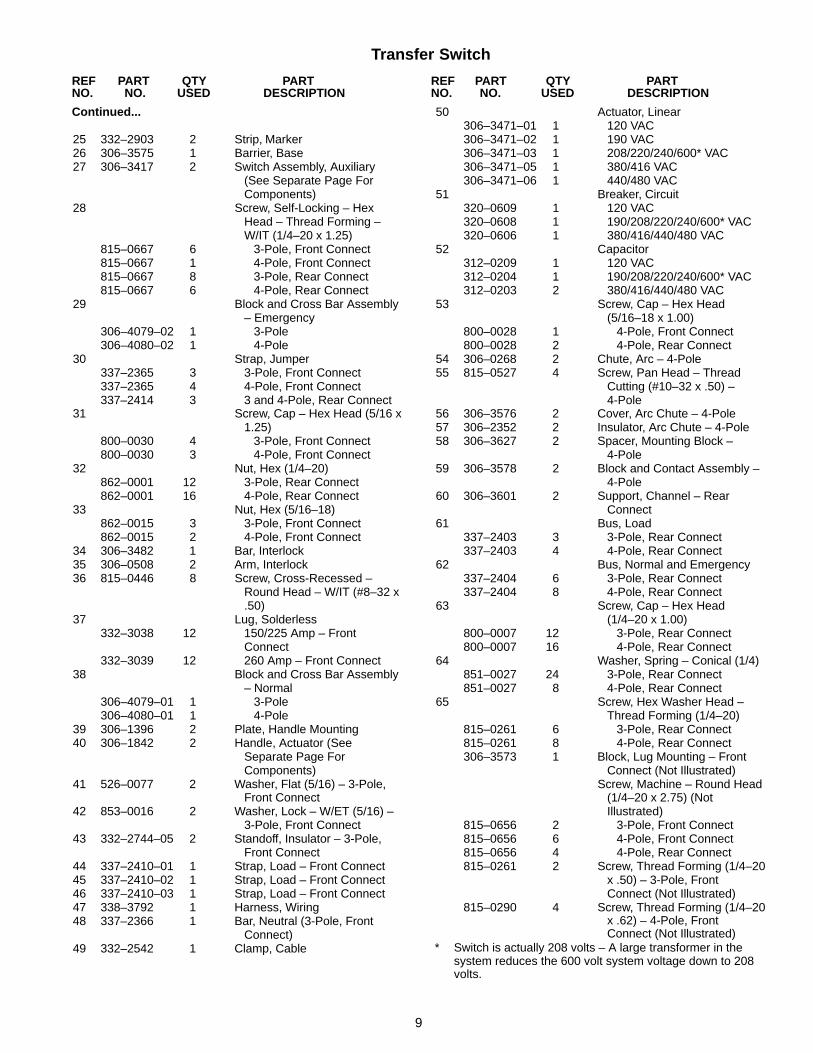
Transfer Switch
REF PART QTY PART REF PART QTY PARTNO. NO. USED DESCRIPTION NO. NO. USED DESCRIPTION
Continued...
25 332–2903 2 Strip, Marker26 306–3575 1 Barrier, Base27 306–3417 2 Switch Assembly, Auxiliary
(See Separate Page ForComponents)
28 Screw, Self-Locking – HexHead – Thread Forming –W/IT (1/4–20 x 1.25)
815–0667 6 3-Pole, Front Connect815–0667 1 4-Pole, Front Connect815–0667 8 3-Pole, Rear Connect815–0667 6 4-Pole, Rear Connect
29 Block and Cross Bar Assembly– Emergency
306–4079–02 1 3-Pole306–4080–02 1 4-Pole
30 Strap, Jumper337–2365 3 3-Pole, Front Connect337–2365 4 4-Pole, Front Connect337–2414 3 3 and 4-Pole, Rear Connect
31 Screw, Cap – Hex Head (5/16 x1.25)
800–0030 4 3-Pole, Front Connect800–0030 3 4-Pole, Front Connect
32 Nut, Hex (1/4–20)862–0001 12 3-Pole, Rear Connect862–0001 16 4-Pole, Rear Connect
33 Nut, Hex (5/16–18)862–0015 3 3-Pole, Front Connect862–0015 2 4-Pole, Front Connect
34 306–3482 1 Bar, Interlock35 306–0508 2 Arm, Interlock36 815–0446 8 Screw, Cross-Recessed –
Round Head – W/IT (#8–32 x.50)
37 Lug, Solderless332–3038 12 150/225 Amp – Front
Connect332–3039 12 260 Amp – Front Connect
38 Block and Cross Bar Assembly– Normal
306–4079–01 1 3-Pole306–4080–01 1 4-Pole
39 306–1396 2 Plate, Handle Mounting40 306–1842 2 Handle, Actuator (See
Separate Page ForComponents)
41 526–0077 2 Washer, Flat (5/16) – 3-Pole,Front Connect
42 853–0016 2 Washer, Lock – W/ET (5/16) –3-Pole, Front Connect
43 332–2744–05 2 Standoff, Insulator – 3-Pole,Front Connect
44 337–2410–01 1 Strap, Load – Front Connect45 337–2410–02 1 Strap, Load – Front Connect46 337–2410–03 1 Strap, Load – Front Connect47 338–3792 1 Harness, Wiring48 337–2366 1 Bar, Neutral (3-Pole, Front
Connect)49 332–2542 1 Clamp, Cable
50 Actuator, Linear306–3471–01 1 120 VAC306–3471–02 1 190 VAC306–3471–03 1 208/220/240/600* VAC306–3471–05 1 380/416 VAC306–3471–06 1 440/480 VAC
51 Breaker, Circuit320–0609 1 120 VAC320–0608 1 190/208/220/240/600* VAC320–0606 1 380/416/440/480 VAC
52 Capacitor312–0209 1 120 VAC312–0204 1 190/208/220/240/600* VAC312–0203 2 380/416/440/480 VAC
53 Screw, Cap – Hex Head(5/16–18 x 1.00)
800–0028 1 4-Pole, Front Connect800–0028 2 4-Pole, Rear Connect
54 306–0268 2 Chute, Arc – 4-Pole55 815–0527 4 Screw, Pan Head – Thread
Cutting (#10–32 x .50) –4-Pole
56 306–3576 2 Cover, Arc Chute – 4-Pole57 306–2352 2 Insulator, Arc Chute – 4-Pole58 306–3627 2 Spacer, Mounting Block –
4-Pole59 306–3578 2 Block and Contact Assembly –
4-Pole60 306–3601 2 Support, Channel – Rear
Connect61 Bus, Load
337–2403 3 3-Pole, Rear Connect337–2403 4 4-Pole, Rear Connect
62 Bus, Normal and Emergency337–2404 6 3-Pole, Rear Connect337–2404 8 4-Pole, Rear Connect
63 Screw, Cap – Hex Head(1/4–20 x 1.00)
800–0007 12 3-Pole, Rear Connect800–0007 16 4-Pole, Rear Connect
64 Washer, Spring – Conical (1/4)851–0027 24 3-Pole, Rear Connect851–0027 8 4-Pole, Rear Connect
65 Screw, Hex Washer Head –Thread Forming (1/4–20)
815–0261 6 3-Pole, Rear Connect815–0261 8 4-Pole, Rear Connect306–3573 1 Block, Lug Mounting – Front
Connect (Not Illustrated)Screw, Machine – Round Head
(1/4–20 x 2.75) (NotIllustrated)
815–0656 2 3-Pole, Front Connect815–0656 6 4-Pole, Front Connect815–0656 4 4-Pole, Rear Connect815–0261 2 Screw, Thread Forming (1/4–20
x .50) – 3-Pole, FrontConnect (Not Illustrated)
815–0290 4 Screw, Thread Forming (1/4–20x .62) – 4-Pole, FrontConnect (Not Illustrated)
* Switch is actually 208 volts – A large transformer in the system reduces the 600 volt system voltage down to 208 volts.

10
Actuator Handle Assembly
1
2
4
6
5
3
REF PART QTY PART REF PART QTY PARTNO. NO. USED DESCRIPTION NO. NO. USED DESCRIPTION
306–1842 2 Handle Assembly, Actuator1 306–1382 1 Handle, Switch – Left Hand2 306–1381 1 Handle, Switch – Right Hand3 815–0932 1 Screw, Machine – Round Head
– Cross Recessed (#8–32 x 2-1/4)
4 815–0933 1 Screw, Machine – Round Head – Cross Recessed
(#10–32 x 1-3/4)5 870–0235 1 Nut, Self-Locking (#8–32)6 870–0298 1 Nut, Self-Locking (#10–32)

11
Auxiliary Switch Assembly
4
5
2
1
3
REF PART QTY PART REF PART QTY PARTNO. NO. USED DESCRIPTION NO. NO. USED DESCRIPTION
306–3417 2 Switch Assembly, Auxiliary1 306–3420 2 Bracket, Switch – Auxiliary2 306–3391 5 Barrier, Switch3 815–0686 2 Screw, Cap – Hex Head
(#6–32 x 3-1/4)
4 870–0201 2 Nut, Lock (#6–32)5 309–0393 4 Switch, Snap-Action

12
CabinetType 1
1
1
2
3
4
5
6
8
24
25
10
14
15
22
19
17
17
18
1112
20
21
16
9
13
7
7
7
26
27
7
2328
13
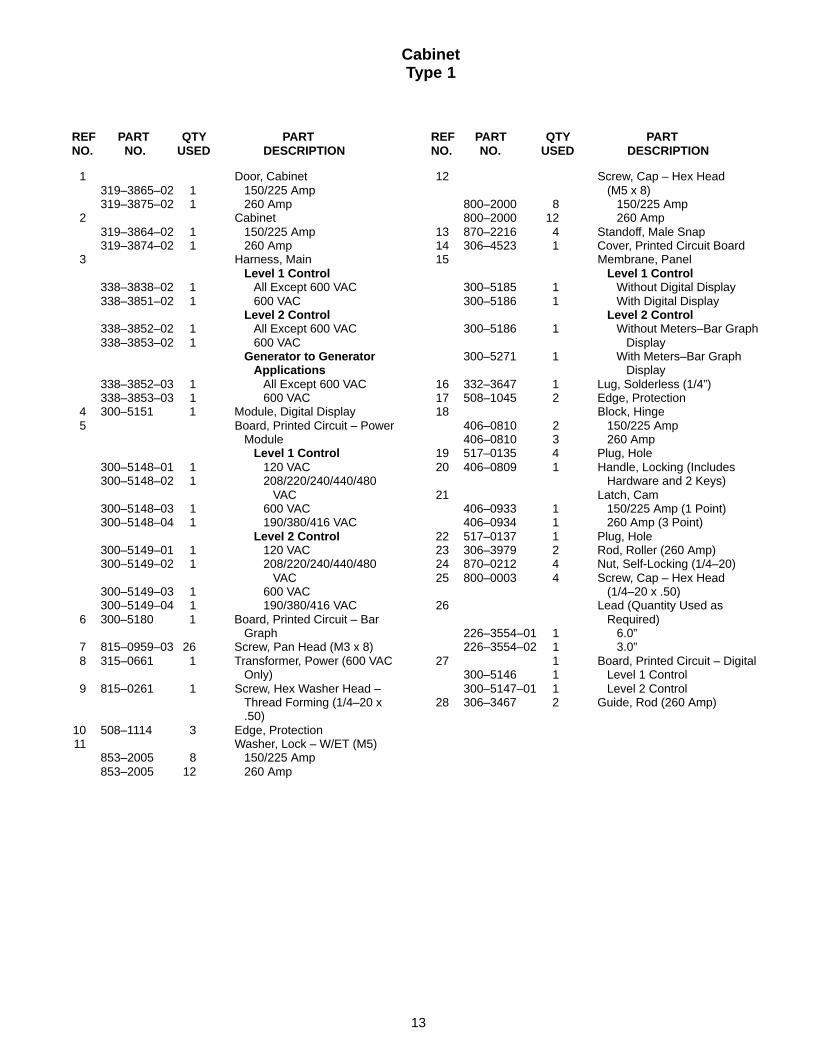
CabinetType 1
REF PART QTY PART REF PART QTY PARTNO. NO. USED DESCRIPTION NO. NO. USED DESCRIPTION
1 Door, Cabinet319–3865–02 1 150/225 Amp319–3875–02 1 260 Amp
2 Cabinet319–3864–02 1 150/225 Amp319–3874–02 1 260 Amp
3 Harness, MainLevel 1 Control
338–3838–02 1 All Except 600 VAC338–3851–02 1 600 VAC
Level 2 Control338–3852–02 1 All Except 600 VAC338–3853–02 1 600 VAC
Generator to Generator Applications
338–3852–03 1 All Except 600 VAC338–3853–03 1 600 VAC
4 300–5151 1 Module, Digital Display5 Board, Printed Circuit – Power
ModuleLevel 1 Control
300–5148–01 1 120 VAC300–5148–02 1 208/220/240/440/480
VAC300–5148–03 1 600 VAC300–5148–04 1 190/380/416 VAC
Level 2 Control300–5149–01 1 120 VAC300–5149–02 1 208/220/240/440/480
VAC300–5149–03 1 600 VAC300–5149–04 1 190/380/416 VAC
6 300–5180 1 Board, Printed Circuit – BarGraph
7 815–0959–03 26 Screw, Pan Head (M3 x 8)8 315–0661 1 Transformer, Power (600 VAC
Only)9 815–0261 1 Screw, Hex Washer Head –
Thread Forming (1/4–20 x.50)
10 508–1114 3 Edge, Protection11 Washer, Lock – W/ET (M5)
853–2005 8 150/225 Amp853–2005 12 260 Amp
12 Screw, Cap – Hex Head(M5 x 8)
800–2000 8 150/225 Amp800–2000 12 260 Amp
13 870–2216 4 Standoff, Male Snap14 306–4523 1 Cover, Printed Circuit Board15 Membrane, Panel
Level 1 Control300–5185 1 Without Digital Display300–5186 1 With Digital Display
Level 2 Control300–5186 1 Without Meters–Bar Graph
Display300–5271 1 With Meters–Bar Graph
Display16 332–3647 1 Lug, Solderless (1/4”)17 508–1045 2 Edge, Protection18 Block, Hinge
406–0810 2 150/225 Amp406–0810 3 260 Amp
19 517–0135 4 Plug, Hole20 406–0809 1 Handle, Locking (Includes
Hardware and 2 Keys)21 Latch, Cam
406–0933 1 150/225 Amp (1 Point)406–0934 1 260 Amp (3 Point)
22 517–0137 1 Plug, Hole23 306–3979 2 Rod, Roller (260 Amp)24 870–0212 4 Nut, Self-Locking (1/4–20)25 800–0003 4 Screw, Cap – Hex Head
(1/4–20 x .50)26 Lead (Quantity Used as
Required)226–3554–01 1 6.0”226–3554–02 1 3.0”
27 1 Board, Printed Circuit – Digital300–5146 1 Level 1 Control300–5147–01 1 Level 2 Control
28 306–3467 2 Guide, Rod (260 Amp)

14
CabinetType 3R and 12
4
7
1
1
2
3
4
5
6
7
7
7
7
8
9
10
11
12
13
14
14
15
16
17
19
19
20
21
22
23
24
1825
15
CabinetType 3R and 12
REF PART QTY PART REF PART QTY PARTNO. NO. USED DESCRIPTION NO. NO. USED DESCRIPTION
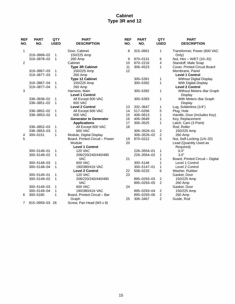
1 Door, Cabinet319–3868–02 1 150/225 Amp319–3878–02 1 260 Amp
2 CabinetType 3R Cabinet
319–3867–03 1 150/225 Amp319–3877–03 1 260 Amp
Type 12 Cabinet319–3867–04 1 150/225 Amp319–3877–04 1 260 Amp
3 Harness, MainLevel 1 Control
338–3838–02 1 All Except 600 VAC338–3851–02 1 600 VAC
Level 2 Control338–3852–02 1 All Except 600 VAC338–3853–02 1 600 VAC
Generator to Generator Applications
338–3852–03 1 All Except 600 VAC338–3853–03 1 600 VAC
4 300–5151 1 Module, Digital Display5 Board, Printed Circuit – Power
ModuleLevel 1 Control
300–5148–01 1 120 VAC300–5148–02 1 208/220/240/440/480
VAC300–5148–03 1 600 VAC300–5148–04 1 190/380/416 VAC
Level 2 Control300–5149–01 1 120 VAC300–5149–02 1 208/220/240/440/480
VAC300–5149–03 1 600 VAC300–5149–04 1 190/380/416 VAC
6 300–5180 1 Board, Printed Circuit – BarGraph
7 815–0959–03 26 Screw, Pan Head (M3 x 8)
8 315–0661 1 Transformer, Power (600 VACOnly)
9 870–0131 6 Nut, Hex – W/ET (10–32)10 870–2216 4 Standoff, Male Snap11 306–4523 1 Cover, Printed Circuit Board12 Membrane, Panel
Level 1 Control300–5391 1 Without Digital Display300–5392 1 With Digital Display
Level 2 Control300–5392 1 Without Meters–Bar Graph
Display300–5393 1 With Meters–Bar Graph
Display13 332–3647 1 Lug, Solderless (1/4”)14 517–0266 5 Plug, Hole15 406–0613 1 Handle, Door (Includes Key)16 406–0649 1 Key, Replacement17 306–3525 1 Latch, Cam (3 Point)18 Rod, Roller
306–3526–01 2 150/225 Amp306–3526–02 2 260 Amp
19 870–0212 5 Nut, Self-Locking (1/4–20)20 Lead (Quantity Used as
Required)226–3554–01 1 6.0”226–3554–02 1 3.0”
21 1 Board, Printed Circuit – Digital300–5146 1 Level 1 Control300–5147–01 1 Level 2 Control
22 508–0233 6 Washer, Rubber23 Gasket, Door
895–0293–03 2 150/225 Amp895–0293–05 2 260 Amp
24 Gasket, Door895–0293–04 2 150/225 Amp895–0293–06 2 260 Amp
25 306–3467 2 Guide, Rod
16
CabinetType 4
4
7
1
1
2
3
4
5
6
7
7
7
7
8
9
10
11
12
13
14
14
15
15
1617
18
19
20
21
22
2324
17
CabinetType 4
REF PART QTY PART REF PART QTY PARTNO. NO. USED DESCRIPTION NO. NO. USED DESCRIPTION
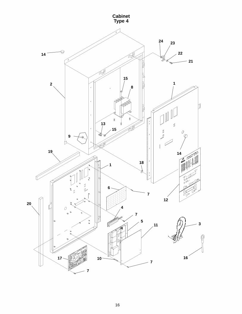
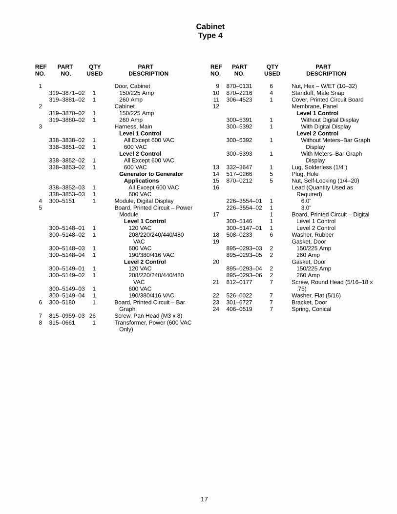
1 Door, Cabinet319–3871–02 1 150/225 Amp319–3881–02 1 260 Amp
2 Cabinet319–3870–02 1 150/225 Amp319–3880–02 1 260 Amp
3 Harness, MainLevel 1 Control
338–3838–02 1 All Except 600 VAC338–3851–02 1 600 VAC
Level 2 Control338–3852–02 1 All Except 600 VAC338–3853–02 1 600 VAC
Generator to Generator Applications
338–3852–03 1 All Except 600 VAC338–3853–03 1 600 VAC
4 300–5151 1 Module, Digital Display5 Board, Printed Circuit – Power
ModuleLevel 1 Control
300–5148–01 1 120 VAC300–5148–02 1 208/220/240/440/480
VAC300–5148–03 1 600 VAC300–5148–04 1 190/380/416 VAC
Level 2 Control300–5149–01 1 120 VAC300–5149–02 1 208/220/240/440/480
VAC300–5149–03 1 600 VAC300–5149–04 1 190/380/416 VAC
6 300–5180 1 Board, Printed Circuit – BarGraph
7 815–0959–03 26 Screw, Pan Head (M3 x 8)8 315–0661 1 Transformer, Power (600 VAC
Only)
9 870–0131 6 Nut, Hex – W/ET (10–32)10 870–2216 4 Standoff, Male Snap11 306–4523 1 Cover, Printed Circuit Board12 Membrane, Panel
Level 1 Control300–5391 1 Without Digital Display300–5392 1 With Digital Display
Level 2 Control300–5392 1 Without Meters–Bar Graph
Display300–5393 1 With Meters–Bar Graph
Display13 332–3647 1 Lug, Solderless (1/4”)14 517–0266 5 Plug, Hole15 870–0212 5 Nut, Self-Locking (1/4–20)16 Lead (Quantity Used as
Required)226–3554–01 1 6.0”226–3554–02 1 3.0”
17 1 Board, Printed Circuit – Digital300–5146 1 Level 1 Control300–5147–01 1 Level 2 Control
18 508–0233 6 Washer, Rubber19 Gasket, Door
895–0293–03 2 150/225 Amp895–0293–05 2 260 Amp
20 Gasket, Door895–0293–04 2 150/225 Amp895–0293–06 2 260 Amp
21 812–0177 7 Screw, Round Head (5/16–18 x.75)
22 526–0022 7 Washer, Flat (5/16)23 301–6727 7 Bracket, Door24 406–0519 7 Spring, Conical
18
Accessory Control Plate(Less than 600 Volt)
CP01
1
2
3
4
6
7
8
6
5
REF PART QTY PART REF PART QTY PARTNO. NO. USED DESCRIPTION NO. NO. USED DESCRIPTION
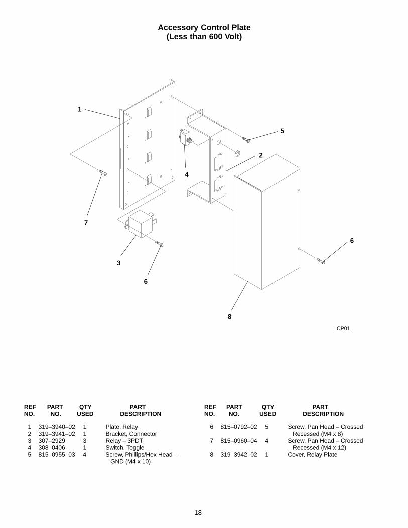
1 319–3940–02 1 Plate, Relay2 319–3941–02 1 Bracket, Connector3 307–2929 3 Relay – 3PDT4 308–0406 1 Switch, Toggle5 815–0955–03 4 Screw, Phillips/Hex Head –
GND (M4 x 10)
6 815–0792–02 5 Screw, Pan Head – CrossedRecessed (M4 x 8)
7 815–0960–04 4 Screw, Pan Head – CrossedRecessed (M4 x 12)
8 319–3942–02 1 Cover, Relay Plate

19
Accessory Control Plate(600 Volt)
R027
1
2
3
4
6
7
8
6
9
10
5
REF PART QTY PART REF PART QTY PARTNO. NO. USED DESCRIPTION NO. NO. USED DESCRIPTION
1 319–3940–02 1 Plate, Relay2 319–3941–02 1 Bracket, Connector3 307–2929 1 Relay – 3PDT4 308–0406 1 Switch, Toggle5 815–0955–03 4 Screw, Phillips/Hex Head –
GND (M4 x 10)6 815–0792–02 3 Screw, Pan Head – Crossed
Recessed (M4 x 8)
7 815–0960–04 4 Screw, Pan Head – CrossedRecessed (M4 x 12)
8 319–3942–02 1 Cover, Relay Plate9 307–2931 2 Relay, Control
10 815–0958–04 4 Screw, Pan Head – CrossRecessed (M3 x 12)

20
Plate and Wiring Harness(Open Construction)
B004, N013
1
2
3
4 5 6
7
8
9
REF PART QTY PART REF PART QTY PARTNO. NO. USED DESCRIPTION NO. NO. USED DESCRIPTION
1 319–4011–02 1 Plate, Open Construction2 517–0266 1 Plug, Hole3 Harness, Control (Optional)
338–2219 1 With 12 Pin Connector (Includes Parts Marked *)
338–2220 1 With 15 Pin Connector (Includes Parts Marked #)
4 323–1314 1 * Plug, Connector (12 Pin) (P2)5 323–1315 1 * Cap, Connector (12 Pin) (J2)
6 *# Socket, Contact323–1200 12 338–2219 Wiring Harness323–1200 15 338–2220 Wiring Harness
7 *# Pin, Contact323–1199 12 338–2219 Wiring Harness323–1199 15 338–2220 Wiring Harness
8 323–1252 1 # Plug, Connector (15 Pin) (P1)9 323–1253 1 # Cap, Connector (15 Pin) (J1)
* – Parts Included in 338–2219 Wiring Harness# – Parts Included in 338–2220 Wiring Harness

21
Wiring HarnessBattery Charger
(Generator Set to Generator Set)
A037
1
9
10
11
12
13
2
3
4
6
7
8
5
REF PART QTY PART REF PART QTY PARTNO. NO. USED DESCRIPTION NO. NO. USED DESCRIPTION
1 332–2879–04 1 Rail, Terminal2 319–3943 1 Plate, Mounting3 307–2873 1 Relay, Control (12 VDC)4 332–2878 2 Bracket, End5 815–0955–03 2 Screw, Phillips/Hex Head –
GND (M4 x 10)6 332–2420 2 Mount, Cable Tie7 870–0212 4 Nut, Self-Locking (1/4–20)8 800–0005 4 Screw, Cap – Hex Head
(1/4–20 x .75)
9 338–3836 1 Harness, Battery Charger(Includes Parts Marked *)
10 323–1200 2 * Socket, Contact11 332–3606 1 * Socket, Contact12 323–1199 2 * Pin, Contact13 323–1703 2 * Pin, Contact
* – Parts Included in 338–3836 Wiring Harness

22
Battery Charger Alarm
N002
10
2
8
1112
1
3
4
5
7
9
6
REF PART QTY PART REF PART QTY PARTNO. NO. USED DESCRIPTION NO. NO. USED DESCRIPTION
1 332–2837–09 1 Rail, Terminal Block2 319–3943 1 Plate, Mounting3 332–2836–02 1 Block, Terminal (Sectional)4 332–2839 2 Bracket, End – Terminal5 332–2841 1 Plate, End – Terminal6 815–0955–03 2 Screw, Phillips/Hex Head –
GND (M4 x 10)7 332–2420 2 Mount, Cable Tie8 870–0212 4 Nut, Self-Locking (1/4–20)
9 800–0005 4 Screw, Cap – Hex Head(1/4–20 x .75)
10 338–2350 1 Harness, Alarm (Includes PartsMarked *)
11 323–1302 9 * Pin, Contact (J2)12 323–1374–10 1 * Housing, Connector (10 Pin)
(J2)
* – Parts Included in 338–2349 Wiring Harness

23
Battery Charger2 Amp, 12/24 Volt
16
17
18
19
20
15
2
5
6
3
1
14
10
11
9
8
4
7
1512
13
21
REF PART QTY PART REF PART QTY PARTNO. NO. USED DESCRIPTION NO. NO. USED DESCRIPTION
1 301–9990 1 Wrapper, Charger – Battery2 301–9991 1 Cover, Charger – Battery3 302–0807 1 Ammeter, DC4 821–0040 4 Screw, Machine – Locking Head
Slotted (#10–32 x 5/16)5 321–0175 1 Holder, Fuse6 321–0153 1 Fuse, 3 Amp7 300–2946 1 Board, Printed Circuit8 Transformer
315–0621–01 1 120 Volt315–0621–02 1 208/240/480 Volt315–0621–03 1 380/416 Volt315–0621–04 1 600 Volt
9 304–0037 1 Resistor, Fixed10 304–0139 1 Resistor, Fixed11 304–0015 4 Washer, Centering (7/32”)12 813–0116 1 Screw, Machine – Round Head
(#10–32 x 6-1/2)
13 813–0112 1 Screw, Machine – Round Head (#10–32 x 2-1/2)
14 870–0131 2 Nut, Hex – W/ET (#10–32)15 815–0845 8 Screw, Pan Head – W/ET
(#6–32 x 3/8)16 338–2149 1 Harness, Wiring
(Includes Parts Marked #)17 323–1318 1 *Cap, 6 pin (J6)18 323–1291 1 *Plug, 9 pin (P9)19 323–1199 A/R *Pin, Terminal20 323–1200 A/R *Socket, Terminal21 862–0026–53 4 Nut, Hex – W/ET (M5)
* – Parts Included in 338–2149 Wiring Harness

24
Battery Charger10 Amp, 12 Volt
17
20
21
18
19
4
15
12
3
6
7
5
2 8 11
10
1
9
12
14 13
22
16
23
24
25
14

25
Battery Charger10 Amp, 12 Volt
REF PART QTY PART REF PART QTY PARTNO. NO. USED DESCRIPTION NO. NO. USED DESCRIPTION
1 319–0072 1 Wrapper, Charger – Battery2 319–0073 1 Cover, Charger – Battery3 302–1844 1 Ammeter, DC4 321–0237 2 Holder, Fuse (AC Input)5 321–0104 1 Holder, Fuse (DC Output)6 Fuse
50 Hertz321–0304–01 2 416/440 Volt321–0304–02 2 380 Volt321–0304–03 2 240 Volt321–0304–04 2 220 Volt
60 Hertz321–0304–01 2 480 Volt321–0304–02 2 380 Volt321–0304–03 2 240 Volt321–0304–04 2 208 Volt321–0304–05 2 120 Volt321–0303–02 2 600 Volt
7 321–0127 1 Fuse (15 Amp)8 Transformer
50 Hertz315–0702 1 380 Volt315–0704 1 220/416/440 Volt315–0712 1 240 Volt
60 Hertz315–0700 1 120/208/240 Volt315–0706 1 380 Volt315–0708 1 480 Volt315–0710 1 600 Volt
9 300–3160 1 PCB, Charger – Battery10 305–0653 1 Rectifier, Bridge11 821–0040 4 Screw, Machine – Locking Head
(#10–32 x 5/16)12 815–0845 8 Screw, Pan Head – W/ET
(#6–32 x 3/8)13 305–0781 1 Rectifier Assembly – SCR
(12 Volt) (Includes Parts Marked *)
14 815–0539 6 Screw, Pan Head – W/ET (#8–32 x 5/8)
15 870–0221 5 Nut, Hex – W/ET (#8–32)16 870–0263 4 *Nut, Insulated (#8)17 338–2223 1 Harness, Battery Charger
(Includes Parts Marked #)18 323–1200 A/R #Socket, Terminal19 323–1302 A/R #Pin, Terminal20 323–1318 1 #Cap, 6 pin21 323–1374–05 1 #Plug, 5 pin22 364–0003 1 *Rectifier, Gate (SCR)23 809–0035 4 *Screw, Sheet Metal – Round
Head (#8 x 3/4)24 226–3554–02 1 Lead (Quantity Used as
Required)25 862–0026–53 4 Nut, Hex – W/ET (M5)
# – Parts Included in 338–2223 Wiring Harness* – Parts Included in 305–0781 Rectifier Assembly
26
Battery Charger10 Amp, 24 Volt
17
20
21
18
19
4
15
12
3
6
14
7
5
2 8 11
10
1
9
12
14 13
22
16
23
24
25
27
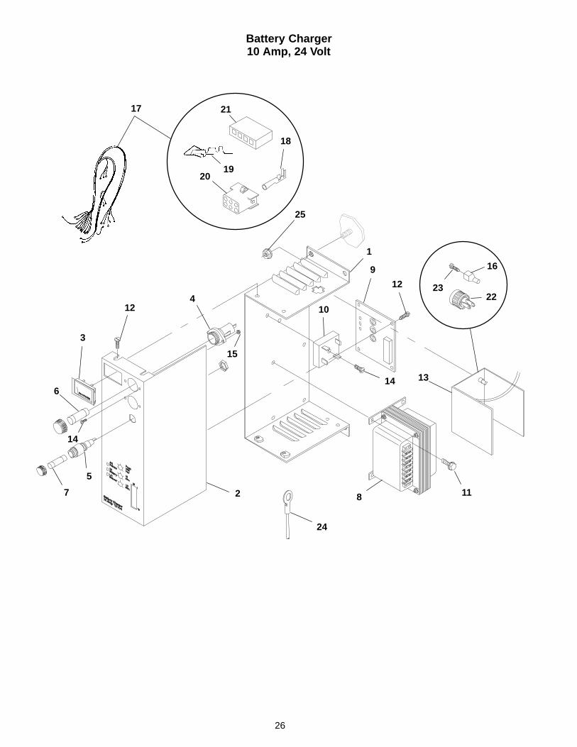
Battery Charger10 Amp, 24 Volt
REF PART QTY PART REF PART QTY PARTNO. NO. USED DESCRIPTION NO. NO. USED DESCRIPTION
1 319–0072 1 Wrapper, Charger – Battery2 319–0073 1 Cover, Charger – Battery
(Includes Silkscreen)3 302–1844 1 Ammeter, DC4 321–0237 2 Holder, Fuse (AC Input)5 321–0104 1 Holder, Fuse (DC Output)6 Fuse
50 Hertz321–0304–04 2 380/416/440 Volt321–0304–05 2 240 Volt321–0304–06 2 220 Volt
60 Hertz321–0303–02 2 600 Volt321–0304–03 2 480 Volt321–0304–04 2 380 Volt321–0304–05 2 240 Volt321–0304–06 2 120/208 Volt
7 321–0127 1 Fuse (15 Amp)8 Transformer
50 Hertz315–0705 1 220/416/440 Volt315–0703 1 380 Volt315–0713 1 240 Volt
60 Hertz315–0701 1 120/208/240 Volt315–0707 1 380 Volt315–0709 1 480 Volt315–0711 1 600 Volt
9 300–3244 1 PCB, Charger – Battery10 305–0653 1 Rectifier, Bridge11 821–0040 4 Screw, Machine – Locking Head
(#10–32 x 5/16)12 815–0845 8 Screw, Pan Head – W/ET
(#6–32 x 3/8)13 305–0781 1 Rectifier Assembly – SCR
(12 Volt) (Includes Parts Marked *)
14 815–0539 6 Screw, Pan Head – W/ET (#8–32 x 5/8)
15 870–0221 5 Nut, Hex – W/ET (#8–32)16 870–0263 4 *Nut, Insulated (#8)17 338–2223 1 Harness, Battery Charger
(Includes Parts Marked #)18 323–1200 A/R #Socket, Terminal19 323–1302 A/R #Pin, Terminal20 323–1318 1 #Cap, 6 pin21 323–1374–05 1 #Plug, 5 pin22 364–0003 1 *Rectifier, Gate (SCR)23 809–0035 4 *Screw, Sheet Metal – Round
Head (#8 x 3/4)24 226–3554–02 1 Lead (Quantity Used as
Required)25 862–0026–53 4 Nut, Hex – W/ET (M5)
# – Parts Included in 338–2223 Wiring Harness* – Parts Included in 305–0781 Rectifier Assembly

28
Network Module
M020
9
1
2
3
4
56
7
10
11
8
REF PART QTY PART REF PART QTY PARTNO. NO. USED DESCRIPTION NO. NO. USED DESCRIPTION
1 300–5153 1 Board, Printed Circuit –Network Module
2 332–2837–09 1 Rail, Terminal Block3 332–2836–01 2 Block, Terminal (Sectional)4 332–2839 2 Bracket, End – Terminal5 332–2841 1 Plate, End – Terminal6 815–0959–03 4 Screw, Pan Head (M3 x 0.5 x 8)
7 870–2213–02 4 Standoff, Hex Thread (M3)8 815–0955–03 2 Screw, Phillips/Hex Head –
GND (M4 x 10)9 338–3886 1 Harness, Network
10 2 Battery – Lithium (3.0V)(Purchase Locally)
11 416–1049 2 Clip, Battery
29
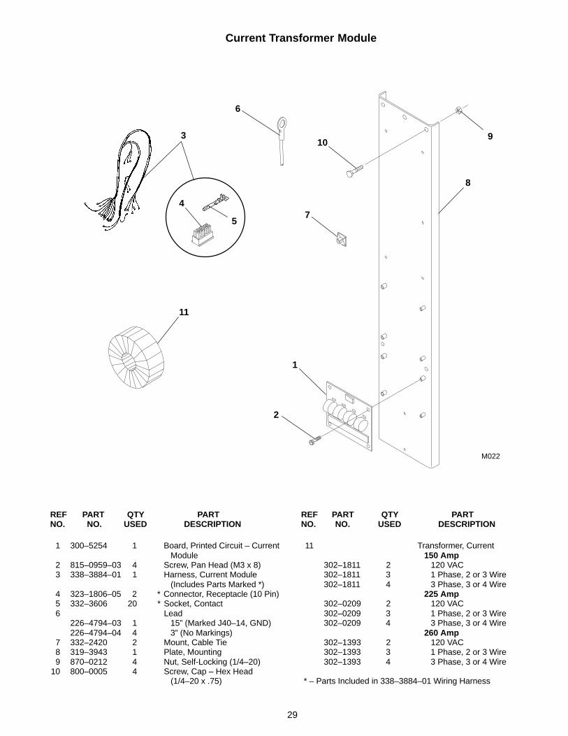
Current Transformer Module
3
5
11
M022
1
2
6
7
8
910
4
REF PART QTY PART REF PART QTY PARTNO. NO. USED DESCRIPTION NO. NO. USED DESCRIPTION
1 300–5254 1 Board, Printed Circuit – CurrentModule
2 815–0959–03 4 Screw, Pan Head (M3 x 8)3 338–3884–01 1 Harness, Current Module
(Includes Parts Marked *)4 323–1806–05 2 * Connector, Receptacle (10 Pin)5 332–3606 20 * Socket, Contact6 Lead
226–4794–03 1 15” (Marked J40–14, GND)226–4794–04 4 3” (No Markings)
7 332–2420 2 Mount, Cable Tie8 319–3943 1 Plate, Mounting9 870–0212 4 Nut, Self-Locking (1/4–20)
10 800–0005 4 Screw, Cap – Hex Head(1/4–20 x .75)
11 Transformer, Current150 Amp
302–1811 2 120 VAC302–1811 3 1 Phase, 2 or 3 Wire302–1811 4 3 Phase, 3 or 4 Wire
225 Amp302–0209 2 120 VAC302–0209 3 1 Phase, 2 or 3 Wire302–0209 4 3 Phase, 3 or 4 Wire
260 Amp302–1393 2 120 VAC302–1393 3 1 Phase, 2 or 3 Wire302–1393 4 3 Phase, 3 or 4 Wire
* – Parts Included in 338–3884–01 Wiring Harness

30
Terminal Block
A037,K001,K002,K003
12
3
4
REF PART QTY PART REF PART QTY PARTNO. NO. USED DESCRIPTION NO. NO. USED DESCRIPTION
1 332–2837–09 1 Rail, Terminal Block2 332–2836–02 3 Block, Terminal (Sectional)
3 332–2839 2 Bracket, End – Terminal4 332–2841 1 Plate, End – Terminal

31
Auxiliary Relay
L201,202,203,204,101,102,103,104
1
2
3
4
REF PART QTY PART REF PART QTY PARTNO. NO. USED DESCRIPTION NO. NO. USED DESCRIPTION
1 332–2879–02 1 Rail, Terminal2 Relay, Control
307–2873 1 12 VDC307–2874 1 24 VDC
3 332–2878 2 Bracket, End4 815–0955–03 2 Screw, Phillips/Hex Head –
GND (M4 x 10)
32
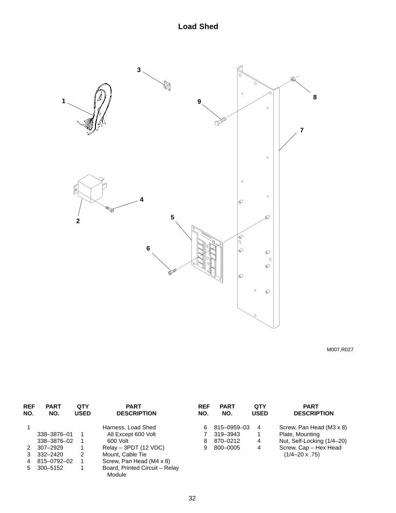
Load Shed
M007,R027
1
2
3
4
5
6
7
89
REF PART QTY PART REF PART QTY PARTNO. NO. USED DESCRIPTION NO. NO. USED DESCRIPTION
1 Harness, Load Shed338–3876–01 1 All Except 600 Volt338–3876–02 1 600 Volt
2 307–2929 1 Relay – 3PDT (12 VDC)3 332–2420 2 Mount, Cable Tie4 815–0792–02 1 Screw, Pan Head (M4 x 8)5 300–5152 1 Board, Printed Circuit – Relay
Module
6 815–0959–03 4 Screw, Pan Head (M3 x 8)7 319–3943 1 Plate, Mounting8 870–0212 4 Nut, Self-Locking (1/4–20)9 800–0005 4 Screw, Cap – Hex Head
(1/4–20 x .75)
33
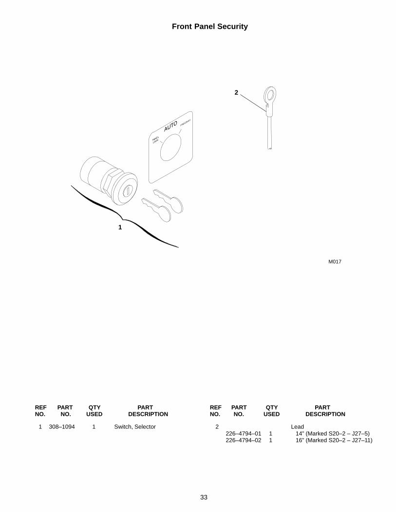
Front Panel Security
M017
2
1
REF PART QTY PART REF PART QTY PARTNO. NO. USED DESCRIPTION NO. NO. USED DESCRIPTION
1 308–1094 1 Switch, Selector 2 Lead226–4794–01 1 14” (Marked S20–2 – J27–5)226–4794–02 1 16” (Marked S20–2 – J27–11)

Numerical Index
Part No. Page Part No. Page Part No. Page Part No. Page
34
226–3380, 7
226–3554–01, 13, 15, 17
226–3554–02, 13, 15, 17,25, 27
226–4794–01, 33
226–4794–02, 33
226–4794–03, 29
226–4794–04, 29
300–2946, 23
300–3160, 25
300–3244, 27
300–5146, 13, 15, 17
300–5147–01, 13, 15, 17
300–5148–01, 13, 15, 17
300–5148–02, 13, 15, 17
300–5148–03, 13, 15, 17
300–5148–04, 13, 15, 17
300–5149–01, 13, 15, 17
300–5149–02, 13, 15, 17
300–5149–03, 13, 15, 17
300–5149–04, 13, 15, 17
300–5151, 13, 15, 17
300–5152, 32
300–5153, 28
300–5180, 13, 15, 17
300–5185, 13
300–5186, 13
300–5254, 29
300–5271, 13
300–5391, 15, 17
300–5392, 15, 17
300–5393, 15, 17
301–6727, 17
301–9990, 23
301–9991, 23
302–0209, 29
302–0807, 23
302–1393, 29
302–1811, 29
302–1844, 25, 27
304–0015, 23
304–0037, 23
304–0139, 23
305–0653, 25, 27
305–0781, 25, 27
306–0268, 9
306–0508, 9
306–1381, 10
306–1382, 10
306–1396, 9
306–1842, 9, 10
306–2340, 7
306–2352, 9
306–3391, 11
306–3400–02, 7
306–3417, 9, 11
306–3418, 7
306–3420, 11
306–3467, 13, 15
306–3471–01, 9
306–3471–02, 9
306–3471–03, 9
306–3471–05, 9
306–3471–06, 9
306–3473, 7
306–3482, 9
306–3483, 7
306–3525, 15
306–3526–01, 15
306–3526–02, 15
306–3573, 9
306–3574, 7
306–3575, 9
306–3576, 9
306–3578, 9
306–3601, 9
306–3627, 9
306–3979, 13
306–4079–01, 9
306–4079–02, 9
306–4080–01, 9
306–4080–02, 9
306–4269, 7
306–4404–01, 7
306–4404–02, 7
306–4404–03, 7
306–4404–04, 7
306–4404–05, 7
306–4404–06, 7
306–4404–07, 7
306–4404–08, 7
306–4404–09, 7
306–4404–10, 7
306–4404–11, 7
306–4404–12, 7
306–4404–13, 7
306–4404–14, 7
306–4404–15, 7
306–4405–02, 7
306–4405–03, 7
306–4405–04, 7
306–4405–05, 7
306–4405–07, 7
306–4405–08, 7
306–4405–09, 7
306–4405–10, 7
306–4405–12, 7
306–4405–13, 7
306–4405–14, 7
306–4405–15, 7
306–4406–01, 7
306–4406–02, 7
306–4406–03, 7
306–4406–04, 7
306–4406–05, 7
306–4406–06, 7
306–4406–07, 7
306–4406–08, 7
306–4406–09, 7
306–4406–10, 7
306–4406–11, 7
306–4406–12, 7
306–4406–13, 7
306–4406–14, 7
306–4406–15, 7
306–4407–02, 7
306–4407–03, 7
306–4407–04, 7
306–4407–05, 7
306–4407–07, 7
306–4407–08, 7
306–4407–09, 7
306–4407–10, 7
306–4407–12, 7
306–4407–13, 7
306–4407–14, 7
306–4407–15, 7
306–4523, 13, 15, 17
307–2873, 21, 31
307–2874, 31
307–2929, 18, 19, 32
307–2931, 19
308–0406, 18, 19
308–1094, 33
309–0393, 11
312–0203, 9
312–0204, 9
312–0209, 9
315–0621–01, 23
315–0621–02, 23
315–0621–03, 23
315–0621–04, 23
315–0661, 13, 15, 17
315–0700, 25
315–0701, 27
315–0702, 25
315–0703, 27
315–0704, 25
315–0705, 27
315–0706, 25
315–0707, 27
315–0708, 25
315–0709, 27
315–0710, 25
315–0711, 27
315–0712, 25
315–0713, 27
319–0072, 25, 27
319–0073, 25, 27
Numerical Index
Part No. Page Part No. Page Part No. Page Part No. Page
35
319–3864–02, 13
319–3865–02, 13
319–3867–03, 15
319–3867–04, 15
319–3868–02, 15
319–3870–02, 17
319–3871–02, 17
319–3874–02, 13
319–3875–02, 13
319–3877–03, 15
319–3877–04, 15
319–3878–02, 15
319–3880–02, 17
319–3881–02, 17
319–3940–02, 18, 19
319–3941–02, 18, 19
319–3942–02, 18, 19
319–3943, 21, 22, 29, 32
319–4011–02, 20
320–0606, 9
320–0608, 9
320–0609, 9
321–0104, 25, 27
321–0127, 25, 27
321–0153, 23
321–0175, 23
321–0237, 25, 27
321–0303–02, 25, 27
321–0304–01, 25
321–0304–02, 25
321–0304–03, 25, 27
321–0304–04, 25, 27
321–0304–05, 25, 27
321–0304–06, 27
323–1199, 20, 21, 23
323–1200, 20, 21, 23, 25, 27
323–1252, 20
323–1253, 20
323–1291, 23
323–1302, 22, 25, 27
323–1314, 20
323–1315, 20
323–1318, 23, 25, 27
323–1374–05, 25, 27
323–1374–10, 22
323–1703, 21
323–1806–05, 29
332–2420, 21, 22, 29, 32
332–2542, 9
332–2605, 7
332–2744–05, 9
332–2832, 7
332–2836–01, 28
332–2836–02, 22, 30
332–2837–09, 22, 28, 30
332–2839, 22, 28, 30
332–2841, 22, 28, 30
332–2878, 21, 31
332–2879–02, 31
332–2879–04, 21
332–2903, 9
332–3038, 9
332–3039, 9
332–3606, 21, 29
332–3647, 13, 15, 17
337–2365, 9
337–2366, 9
337–2403, 9
337–2404, 9
337–2410–01, 9
337–2410–02, 9
337–2410–03, 9
337–2414, 9
338–2149, 23
338–2219, 20
338–2220, 20
338–2223, 25, 27
338–2350, 22
338–3792, 9
338–3836, 21
338–3838–02, 13, 15, 17
338–3851–02, 13, 15, 17
338–3852–02, 13, 15, 17
338–3852–03, 13, 15, 17
338–3853–02, 13, 15, 17
338–3853–03, 13, 15, 17
338–3876–01, 32
338–3876–02, 32
338–3884–01, 29
338–3886, 28
364–0003, 25, 27
406–0519, 17
406–0613, 15
406–0649, 15
406–0809, 13
406–0810, 13
406–0933, 13
406–0934, 13
416–1049, 28
508–0233, 15, 17
508–1045, 13
508–1114, 13
517–0135, 13
517–0137, 13
517–0266, 15, 17, 20
526–0008, 7
526–0018, 7
526–0022, 17
526–0077, 9
800–0003, 7, 13
800–0005, 21, 22, 29, 32
800–0007, 9
800–0008, 7
800–0021, 7
800–0027, 7
800–0028, 9
800–0030, 9
800–2000, 13
809–0035, 25, 27
812–0177, 17
813–0112, 23
813–0116, 23
815–0029, 7
815–0261, 9, 13
815–0290, 9
815–0446, 9
815–0527, 9
815–0539, 25, 27
815–0651, 7
815–0652, 7
815–0656, 9
815–0667, 9
815–0686, 11
815–0792–02, 18, 19, 32
815–0845, 23, 25, 27
815–0932, 10
815–0933, 10
815–0955–03, 18, 19, 21,22, 28, 31
815–0958–04, 19
815–0959–03, 13, 15, 17,28, 29, 32
815–0960–04, 18, 19
821–0040, 23, 25, 27
850–0040, 7
851–0027, 9
851–0028, 7
853–0016, 9
853–2005, 13
862–0001, 9
862–0015, 9
862–0026–53, 23, 25, 27
870–0131, 7, 15, 17, 23
870–0201, 11
870–0212, 13, 15, 17, 21,22, 29, 32
870–0221, 25, 27
870–0235, 10
870–0263, 25, 27
870–0281, 7
870–0298, 10
870–0320, 7
870–2213–02, 28
870–2216, 13, 15, 17
895–0293–03, 15, 17
895–0293–04, 15, 17
895–0293–05, 15, 17
895–0293–06, 15, 17

Cummins Power Generation1400 73rd Avenue N.E.Minneapolis, MN 554321-800-888-6266763-574-5000 International UseFax: 763-574-8087
Cummins is a registered trademark of Cummins Inc.