Embed Size (px)
Citation preview
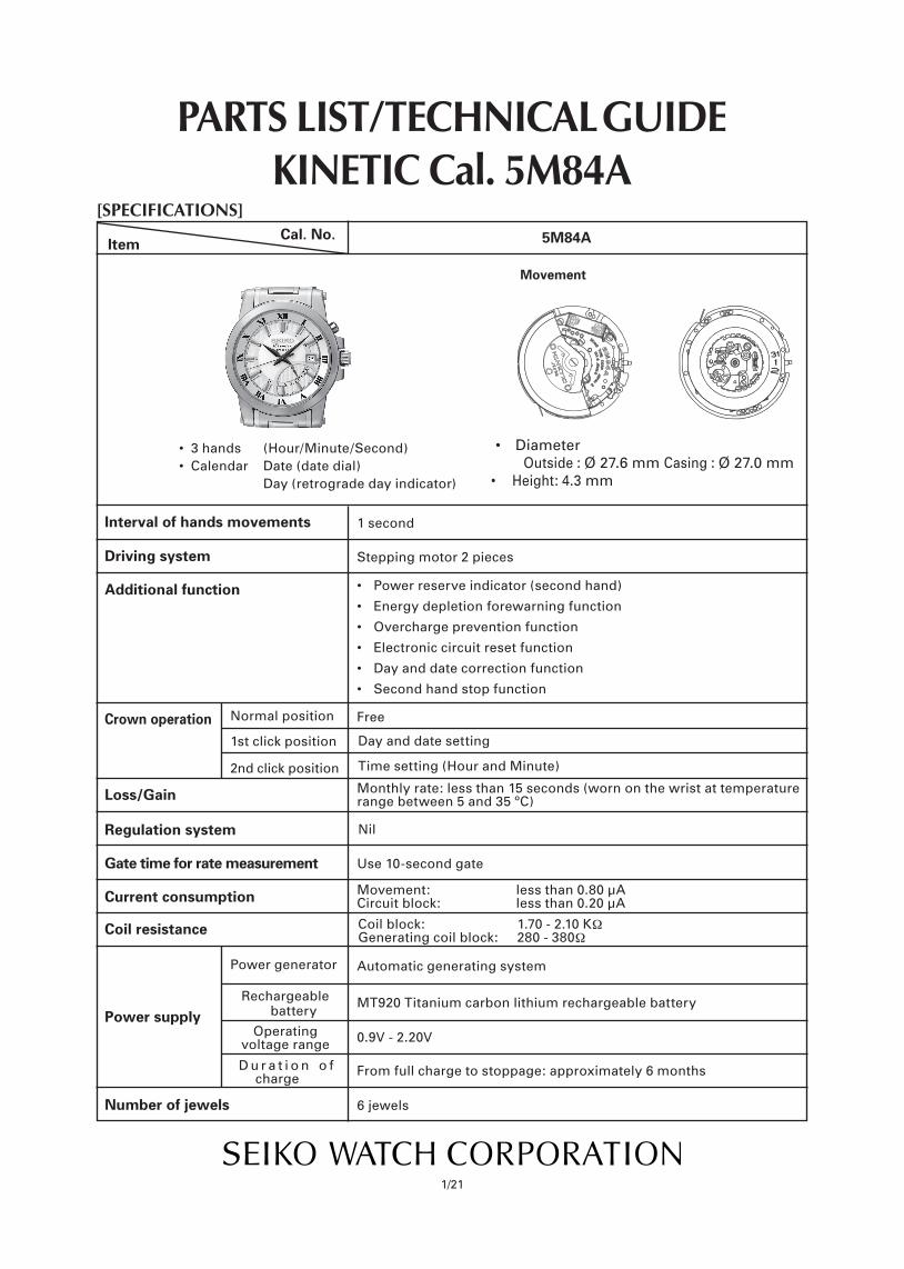
[SPECIFICATIONS]
ItemCal. No.
Power generator
Rechargeable battery
Monthly rate: less than 15 seconds (worn on the wrist at temperature range between 5 and 35 ºC)
Nil
Use 10-second gate
Movement: less than 0.80 µA Circuit block: less than 0.20 µA
Automatic generating system
MT920 Titanium carbon lithium rechargeable battery
0.9V - 2.20V
From full charge to stoppage: approximately 6 months
6 jewels
1/21
PARTS LIST/ TECHNICAL GUIDEKINETIC Cal. 5M84A
5M84A
Driving system
Additional function
Crown operation
Loss/Gain
Regulation system
Gate time for rate measurement
Current consumption
Power supplyOperating
voltage range
D u r a t i o n o f charge
Number of jewels
Interval of hands movements
Normal position
1st click position
2nd click position
Coil resistance
• 3hands (Hour/Minute/Second)•Calendar Date(datedial) Day (retrograde day indicator)
1 second
Steppingmotor2pieces
• Powerreserveindicator(secondhand)
• Energydepletionforewarningfunction
• Overchargepreventionfunction
• Electroniccircuitresetfunction
• Dayanddatecorrectionfunction
• Secondhandstopfunction
Free
Day and date setting
• Diameter Outside : Ø 27.6 mm Casing : Ø 27.0 mm • Height:4.3 mm
Timesetting(HourandMinute)
5M84A
Movement
Coil block: 1.70 - 2.10 KΩGenerating coil block: 280 - 380Ω
Cal. 5M84A
2/21
SPECIFICATIONS
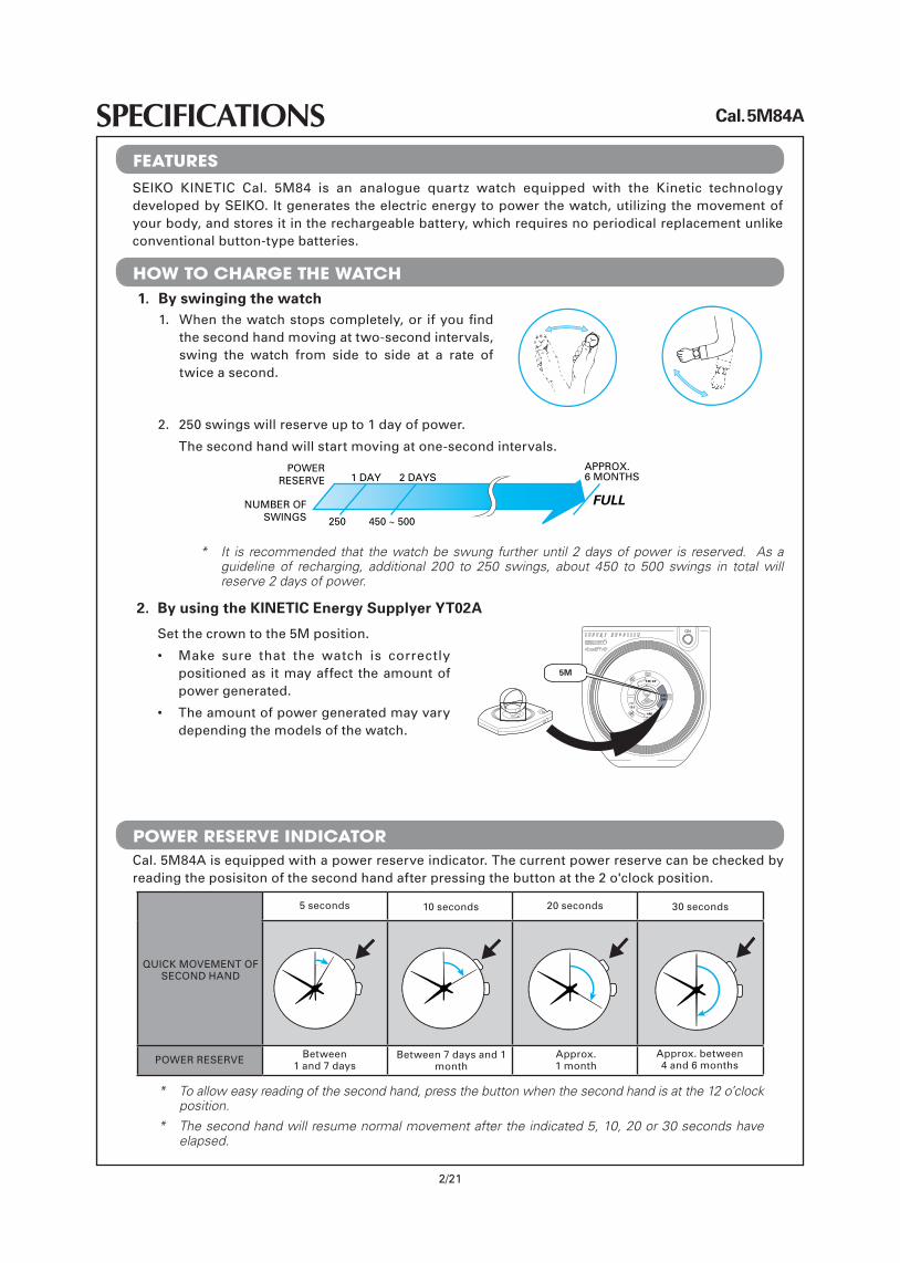
10 seconds 20 seconds 30 seconds
Between 7 days and 1 month
Approx.1 month
Approx. between4and6months
Between1 and 7 days
5 seconds
POWERRESERVE
QUICKMOVEMENTOFSECONDHAND
SEIKO KINETIC Cal. 5M84 is an analogue quartz watch equipped with the Kinetic technologydevelopedbySEIKO. Itgeneratestheelectricenergytopowerthewatch,utilizingthemovementofyourbody,andstoresitintherechargeablebattery,whichrequiresnoperiodicalreplacementunlikeconventional button-type batteries.
1. Whenthewatchstopscompletely,or ifyoufindthesecondhandmovingattwo-secondintervals,swing the watch from side to side at a rate of twice a second.
1. By swinging the watch
2. By using the KINETIC Energy Supplyer YT02A
2. 250 swings will reserve up to 1 day of power.
The second hand will start moving at one-second intervals.
Setthecrowntothe5Mposition.
• Make sure that the watch is correctlypositioned as it may affect the amount of power generated.
• Theamountofpowergeneratedmayvarydepending the models of the watch.
5M
Cal.5M84Aisequippedwithapowerreserveindicator.Thecurrentpowerreservecanbecheckedbyreading the posisiton of the second hand after pressing the button at the 2 o'clock position.
* The second hand will resume normal movement after the indicated 5, 10, 20 or 30 seconds have elapsed.
* To allow easy reading of the second hand, press the button when the second hand is at the 12 o’clock position.
* It is recommended that the watch be swung further until 2 days of power is reserved. As a guideline of recharging, additional 200 to 250 swings, about 450 to 500 swings in total will reserve 2 days of power.
POWER RESERVE INDICATOR
POWERRESERVE
NUMBER OFSWINGS 250 450 ~ 500
1 DAY 2 DAYSAPPROX.6 MONTHS
FULL
FEATURES
HOW TO CHARGE THE WATCH
Cal. 5M84A
3/21
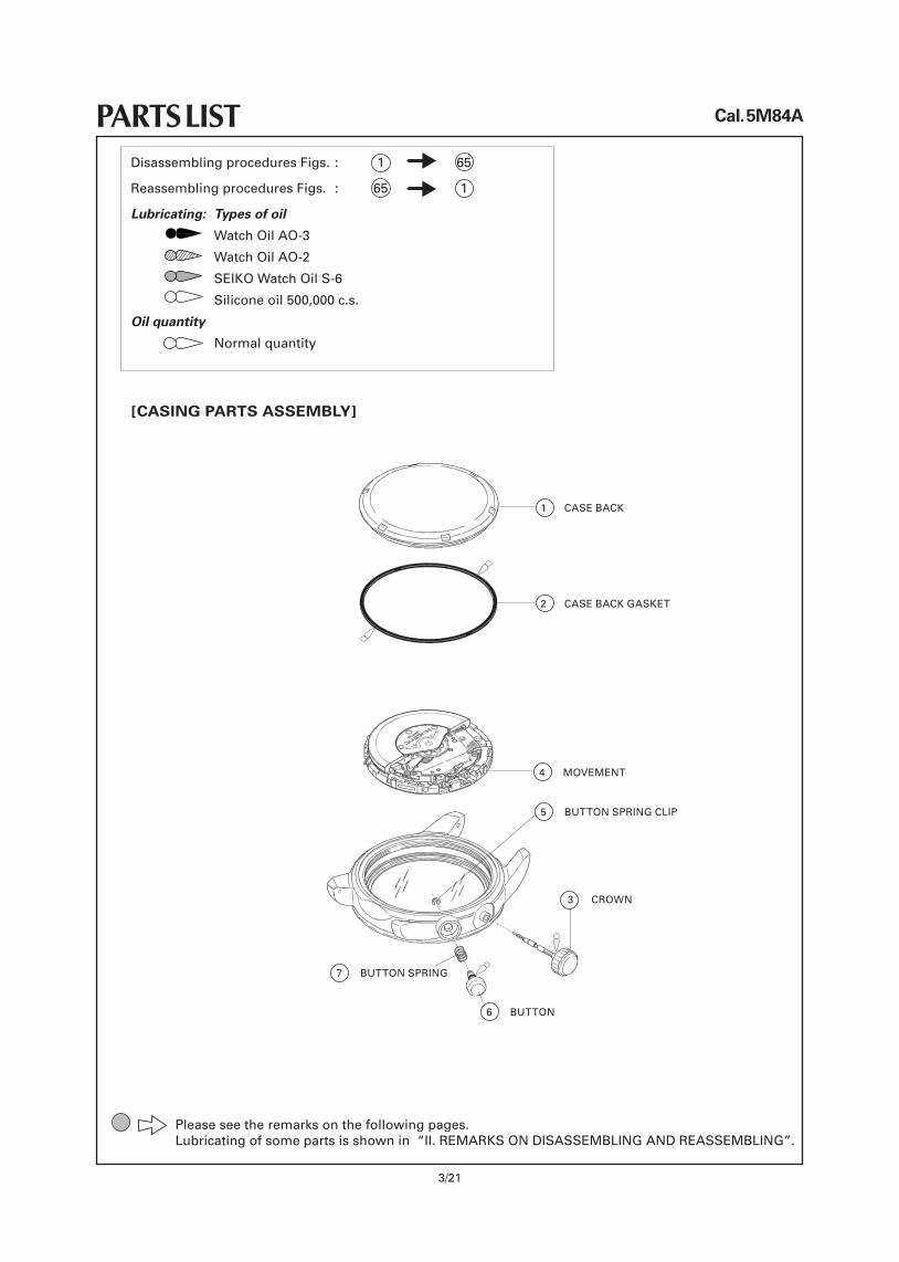
PARTS LISTDisassembling procedures Figs. : 1 65
Reassembling procedures Figs. : 65 1
Lubricating: Types of oil
Watch Oil AO-3
Watch Oil AO-2
SEIKOWatchOilS-6
Siliconeoil500,000c.s.
Oil quantity
Normalquantity
Please see the remarks on the following pages.Lubricatingofsomepartsisshownin“II.REMARKSONDISASSEMBLINGANDREASSEMBLING”.
1 CASEBACK
2 CASEBACKGASKET
4 MOVEMENT
7 BUTTONSPRING
5 BUTTONSPRINGCLIP
6 BUTTON
3 CROWN
[CASING PARTS ASSEMBLY]
26
27
28
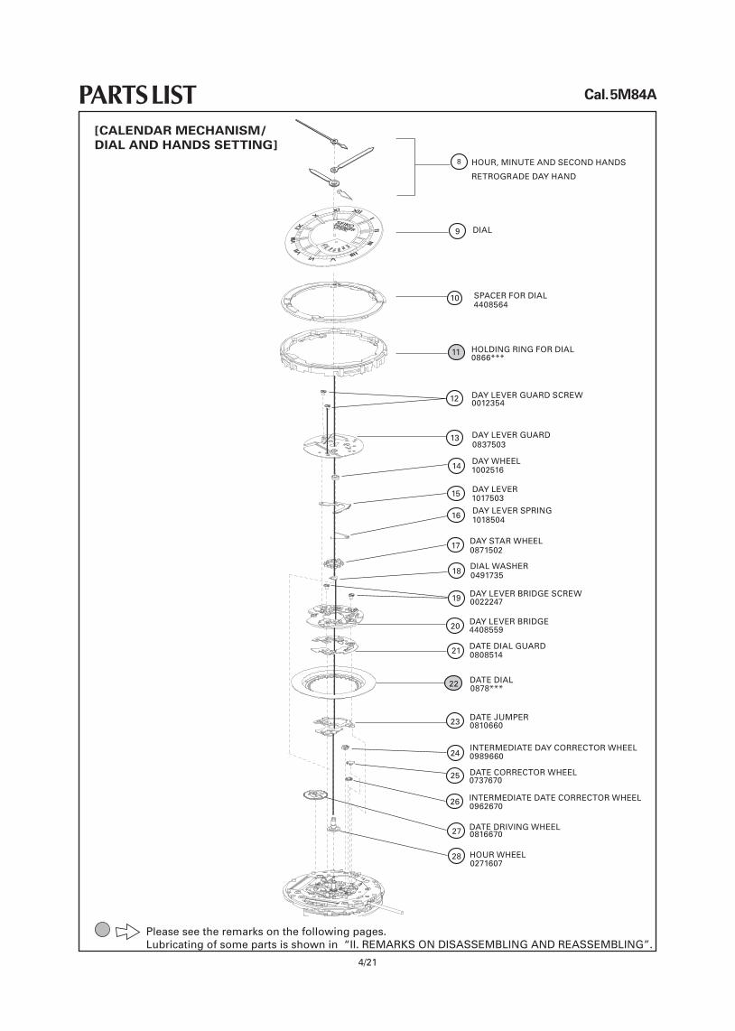
0012354DAY LEVER GUARD SCREW
0837503DAY LEVER GUARD
1002516DAY WHEEL
1017503DAY LEVER
1018504DAY LEVER SPRING
0871502DAY STAR WHEEL
0491735DIAL WASHER
0022247DAY LEVER BRIDGE SCREW
0808514DATE DIAL GUARD
0878***DATE DIAL
0810660DATE JUMPER
0989660INTERMEDIATE DAY CORRECTOR WHEEL
0737670DATE CORRECTOR WHEEL
0962670INTERMEDIATE DATE CORRECTOR WHEEL
0816670DATE DRIVING WHEEL
0271607HOUR WHEEL
DAY LEVER BRIDGE
HOLDING RING FOR DIAL0866***
11
12
14
15
16
17
18
19
20
21
22
23
24
25
SPACER FOR DIAL104408564
4408559
XIII
IIIII
IIII
II
VVI
VVIII
XI
XXI
SEIKOPREMIERKINETIC
MONTUEWEDTHU
FRI
SAT
SUN
RETROGRADE DAY HAND
DIAL
HOUR, MINUTE AND SECOND HANDS
9
8
13
Cal. 5M84A
4/21
PARTS LIST
Please see the remarks on the following pages.Lubricatingofsomepartsisshownin“II.REMARKSONDISASSEMBLINGANDREASSEMBLING”.
[CALENDAR MECHANISM/ DIAL AND HANDS SETTING]
Cal. 5M84A
5/21
PARTS LIST
Please see the remarks on the following pages.Lubricatingofsomepartsisshownin“II.REMARKSONDISASSEMBLINGANDREASSEMBLING”.
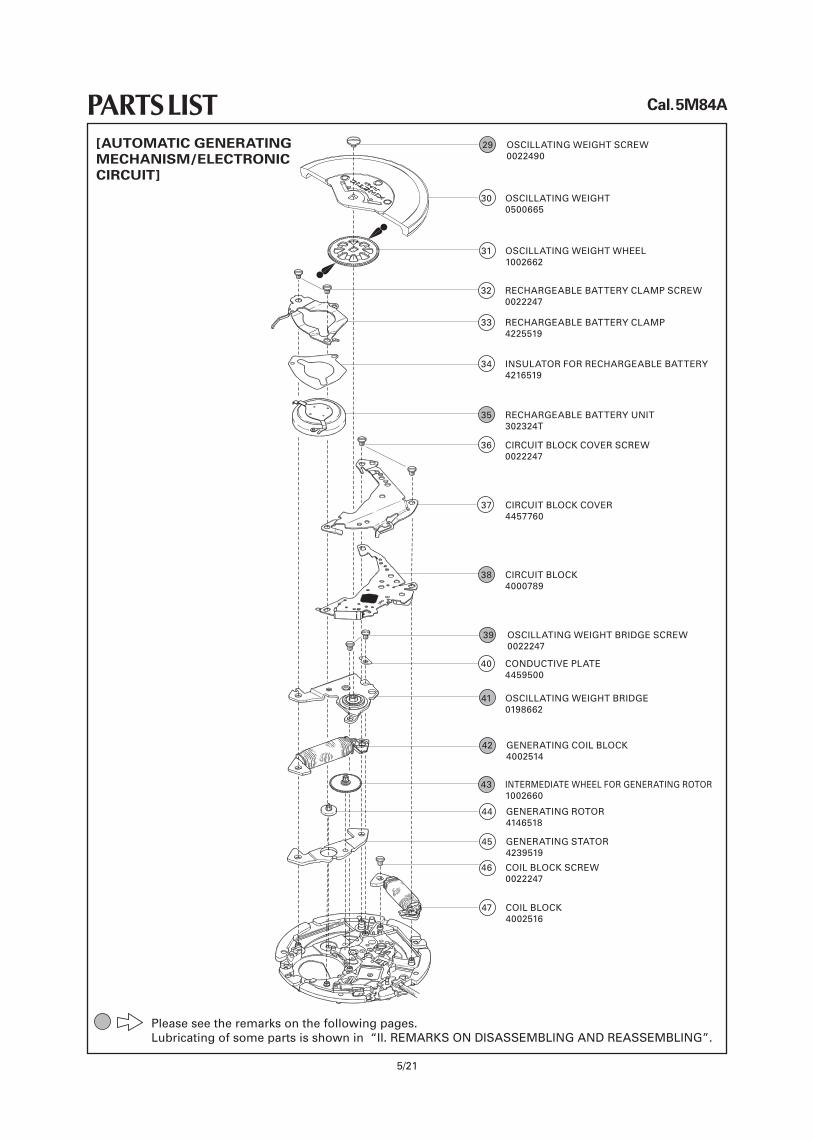
29 OSCILLATINGWEIGHTSCREW 0022490
30 OSCILLATINGWEIGHT 0500665
31 OSCILLATINGWEIGHTWHEEL 1002662
32 RECHARGEABLEBATTERYCLAMPSCREW 0022247
33 RECHARGEABLEBATTERYCLAMP 4225519
35 RECHARGEABLEBATTERYUNIT 302324T
36 CIRCUITBLOCKCOVERSCREW 0022247
37 CIRCUITBLOCKCOVER 4457760
38 CIRCUIT BLOCK 4000789
39 OSCILLATINGWEIGHTBRIDGESCREW 0022247
40 CONDUCTIVEPLATE 4459500
41 OSCILLATINGWEIGHTBRIDGE 0198662
42 GENERATINGCOILBLOCK 4002514
43 INTERMEDIATEWHEELFORGENERATINGROTOR 1002660
34 INSULATORFORRECHARGEABLEBATTERY 4216519
44 GENERATINGROTOR 4146518
45 GENERATINGSTATOR 4239519
46 COILBLOCKSCREW 0022247
47 COILBLOCK 4002516
[AUTOMATIC GENERATING MECHANISM/ELECTRONIC CIRCUIT]
Cal. 5M84A
6/21
PARTS LIST
Please see the remarks on the following pages.Lubricatingofsomepartsisshownin“II.REMARKSONDISASSEMBLINGANDREASSEMBLING”.
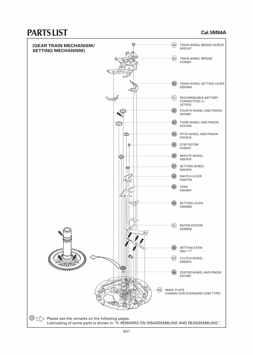
49 TRAINWHEEL BRIDGE 0125661
50 TRAINWHEELSETTINGLEVER 0391660
51 RECHARGEABLEBATTERY CONNECTION(+) 4271515
52 FOURTHWHEELANDPINION 0241667
54 FIFTHWHEELANDPINION 0701670
55 STEPROTOR 4146531
56 MINUTEWHEEL 0261670
57 SETTINGWHEEL 0281670
58 SWITCHLEVER 4450730
59 YOKE 0384661
60 SETTINGLEVER 0383662
61 ROTORSTATOR 4239559
62 SETTINGSTEM 0351 ***
63 CLUTCHWHEEL 0282672
64 CENTERWHEELANDPINION 0221667
65 MAINPLATE 0100564(FORSTANDARDCASETYPE)
53 THIRDWHEELANDPINION 0231530
48 TRAINWHEELBRIDGESCREW 0022247
[GEAR TRAIN MECHANISM/SETTING MECHANISM]
Cal. 5M84A
7/21
PARTS LIST
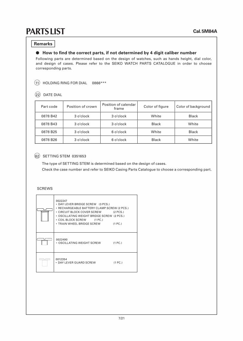
l How to find the correct parts, if not determined by 4 digit caliber numberFollowing parts are determined based on the design of watches, such as hands height, dial color,and design of cases. Please refer to the SEIKO WATCH PARTS CATALOGUE in order to choosecorresponding parts.
Remarks
0022247• DAYLEVERBRIDGESCREW (3PCS.)• RECHARGEABLEBATTERYCLAMPSCREW(2PCS.)• CIRCUITBLOCKCOVERSCREW (2PCS.)• OSCILLATINGWEIGHTBRIDGESCREW(2PCS.)• COILBLOCKSCREW (1PC.)• TRAINWHEELBRIDGESCREW (1PC.)
0022490• OSCILLATINGWEIGHTSCREW (1PC.)
0012354• DAYLEVERGUARDSCREW (1PC.)
11 HOLDINGRINGFORDIAL0866***
22 DATEDIAL
Part code Position of crown Position of calendar frame Coloroffigure Color of background
0878B42 3 o'clock 3 o'clock White Black
0878B43 3 o'clock 3 o'clock Black White
0878 B25 3 o'clock 6 o'clock White Black
0878 B26 3 o'clock 6 o'clock Black White
62 SETTINGSTEM0351653
ThetypeofSETTINGSTEMisdeterminedbasedonthedesignofcases.
CheckthecasenumberandrefertoSEIKOCasingPartsCataloguetochooseacorrespondingpart.
SCREWS
Cal. 5M84A
8/21
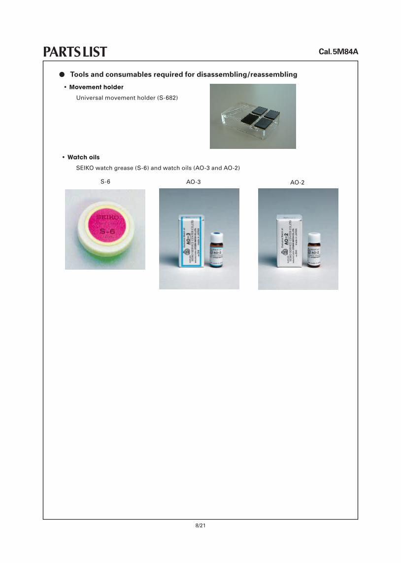
PARTS LISTl Tools and consumables required for disassembling/reassembling
• Movement holder
Universalmovementholder(S-682)
• Watch oils
SEIKOwatchgrease(S-6)andwatchoils(AO-3andAO-2)
S-6 AO-2AO-3
Cal. 5M84A
9/21
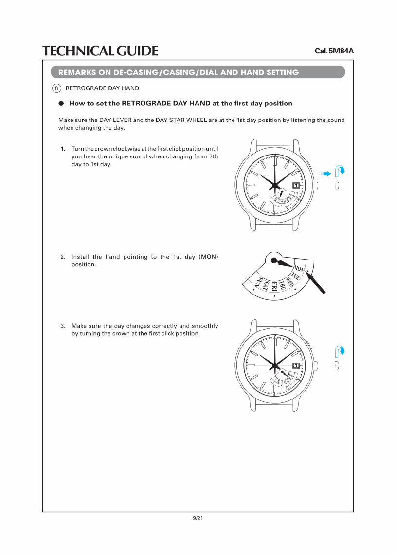
TECHNICAL GUIDEREMARKS ON DE-CASING/CASING/DIAL AND HAND SETTING
l How to set the RETROGRADE DAY HAND at the first day position
MONTUEWED
THUFRI
SATSUN
Make sure the DAYLEVER and the DAYSTARWHEELare at the 1st day position by listening the sound when changing the day.
1. Turnthecrownclockwiseatthefirstclickpositionuntilyouheartheuniquesoundwhenchangingfrom7thday to 1st day.
2. Install the hand pointing to the 1st day (MON) position. MON
TUEWEDTHUFRI
SATSUN
3. Make sure the day changes correctly and smoothly byturningthecrownatthefirstclickposition.
MONTUEWED
THUFRI
SATSUN
8 RETROGRADEDAYHAND
Cal. 5M84A
10/21
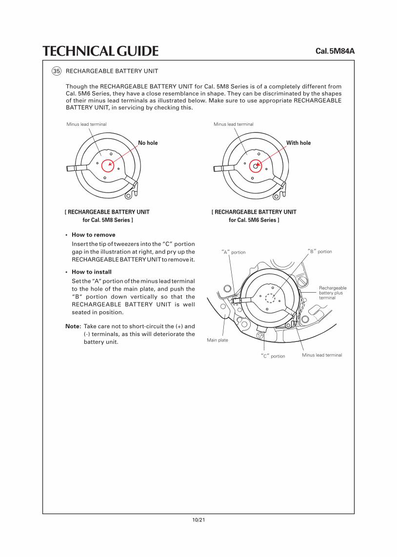
TECHNICAL GUIDE35 RECHARGEABLEBATTERYUNIT
ThoughtheRECHARGEABLEBATTERYUNITforCal.5M8SeriesisofacompletelydifferentfromCal.5M6Series,theyhaveacloseresemblanceinshape.Theycanbediscriminatedbytheshapesoftheirminusleadterminalsasillustratedbelow.MakesuretouseappropriateRECHARGEABLEBATTERYUNIT,inservicingbycheckingthis.
Minus lead terminal
[ RECHARGEABLE BATTERY UNIT for Cal. 5M8 Series ]
• How to remove
Insertthetipoftweezersintothe“C”モportion gapintheillustrationatright,andpryuptheRECHARGEABLEBATTERYUNITtoremoveit.
• How to install
Setthe“A“ portion of the minus lead terminal totheholeofthemainplate,andpushthe“B“ portion down vertically so that the RECHARGEABLE BATTERY UNIT is wellseated in position.
Note: Takecarenottoshort-circuitthe(+)and(-)terminals,asthiswilldeterioratethebattery unit.
“A“ portion
Main plate
メ“C“ portion Minus lead terminal
Rechargeable battery plus terminal
メ“B“ portion
Minus lead terminal
[ RECHARGEABLE BATTERY UNIT for Cal. 5M6 Series ]
No hole With hole
Cal. 5M84A
11/21
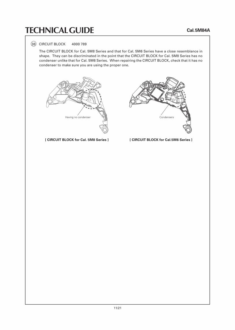
TECHNICAL GUIDE38 CIRCUITBLOCK 4000789
[ CIRCUIT BLOCK for Cal.5M6 Series ][ CIRCUIT BLOCK for Cal. 5M8 Series ]
TheCIRCUITBLOCKforCal.5M8SeriesandthatforCal.5M6Serieshaveacloseresemblanceinshape.TheycanbediscriminatedinthepointthattheCIRCUITBLOCKforCal.5M8SerieshasnocondenserunlikethatforCal.5M6Series.WhenrepairingtheCIRCUITBLOCK,checkthatithasnocondenser to make sure you are using the proper one.
Having no condenser Condensers
Cal. 5M84A
12/21
TECHNICAL GUIDEREMARKS ON DISSASEMBLING AND REASSEMBLING THE MOVEMENT
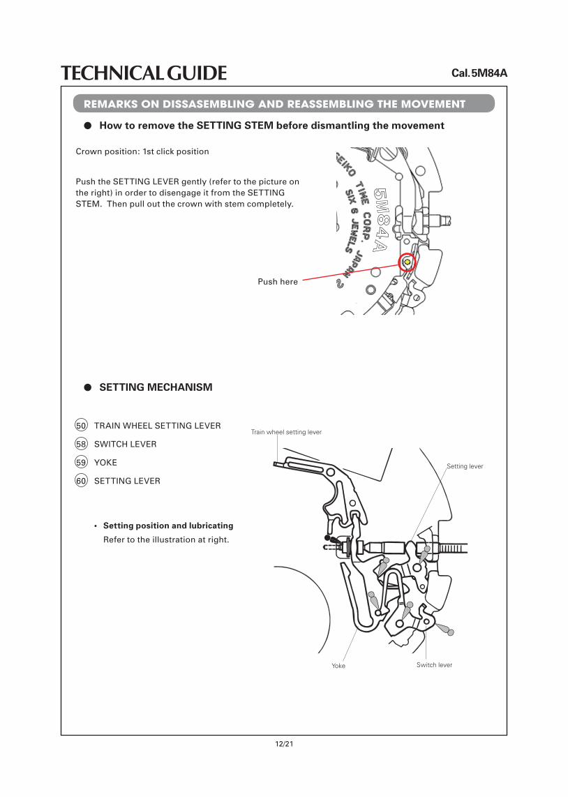
l How to remove the SETTING STEM before dismantling the movement
50 TRAINWHEELSETTINGLEVER
58 SWITCHLEVER
59 YOKE
60 SETTINGLEVER
• Settingpositionandlubricating
Refer to the illustration at right.
Train wheel setting lever
Setting lever
Switch leverYoke
l SETTING MECHANISM
Crown position: 1st click position
PushtheSETTINGLEVERgently(refertothepictureontheright)inordertodisengageitfromtheSETTINGSTEM.Thenpulloutthecrownwithstemcompletely.
Push here
Cal. 5M84A
13/21
TECHNICAL GUIDE
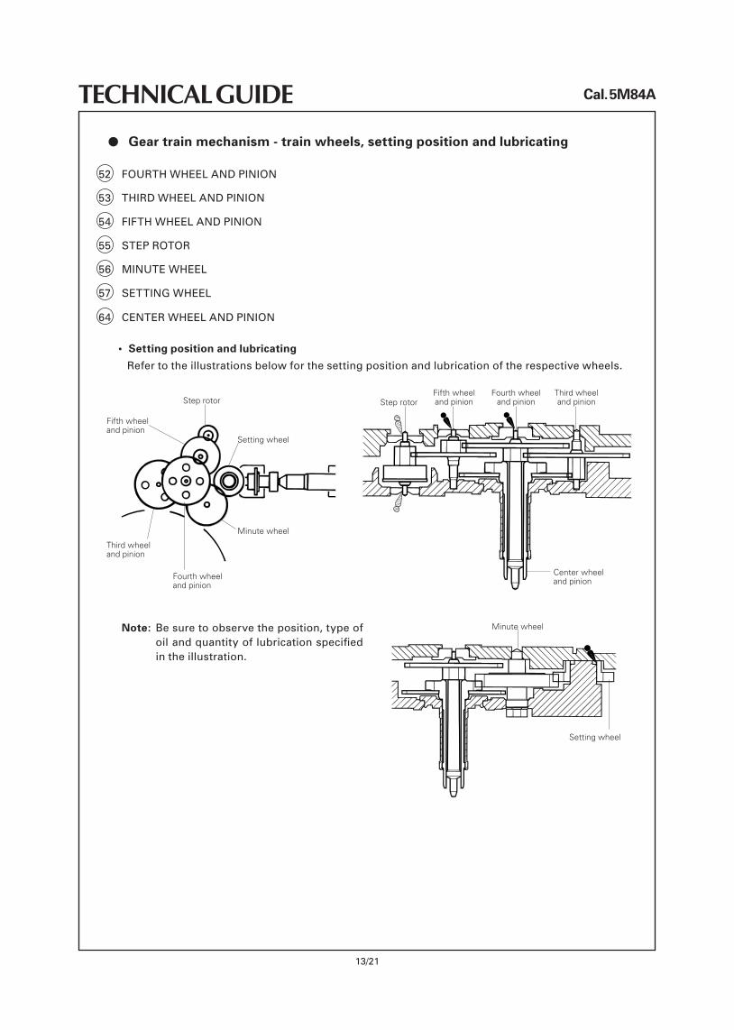
l Gear train mechanism - train wheels, setting position and lubricating
52 FOURTHWHEELANDPINION
53 THIRDWHEELANDPINION
54 FIFTHWHEELANDPINION
55 STEPROTOR
56 MINUTEWHEEL
57 SETTINGWHEEL
• Settingpositionandlubricating
Refer to the illustrations below for the setting position and lubrication of the respective wheels.
Fifth wheel and pinion
Step rotor
Setting wheel
Fourth wheel and pinion
Minute wheel
Third wheel and pinion
Center wheel and pinion
Step rotorFifth wheel and pinion
Fourth wheel and pinion
Third wheel and pinion
64 CENTERWHEELANDPINION
Note: Besuretoobservetheposition,typeofoilandquantityoflubricationspecifiedin the illustration.
Minute wheel
Setting wheel
Cal. 5M84A
14/21
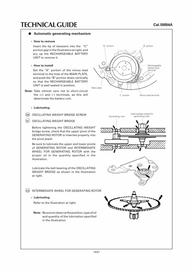
TECHNICAL GUIDEl Automatic generating mechanism
• Howtoremove
Insert the tip of tweezers into the “C”portiongapintheillustrationatright,andpry up the RECHARGEABLE BATTERYUNIT to remove it.
• Howtoinstall
Set the “A” portion of the minus leadterminal to the hole of the MAINPLATE,andpushthe“B”portiondownverticallyso that the RECHARGEABLE BATTERYUNIT is well seated in position.
Note: Take utmost care not to short-circuit the (+) and (-) terminals, as this willdeteriorate the battery unit.
“A” portion
Main plate
メCメ portion Minus lead terminal
Rechargeable battery plus terminal
メBメ portion
39 OSCILLATINGWEIGHTBRIDGESCREW
41 OSCILLATINGWEIGHTBRIDGE
Before tightening the OSCILLATING WEIGHTbridgescrew,checkthattheupperpivotoftheGENERATINGROTOR is inserted properly into the pivot jewel.
Be sure to lubricate the upper and lower pivots of GENERATING ROTOR and INTERMEDIATEWHEEL FOR GENERATING ROTOR with the proper oil in the quantity specified in theillustration.
Lubricate the ball-bearing of the OSCILLATINGWEIGHT BRIDGE as shown in the illustration at right.
Intermediate wheel for generating rotorGenerating rotor
43 INTERMEDIATEWHEELFORGENERATINGROTOR
• Lubricating
Refer to the illustration at right.
Note: Besuretoobservetheposition,typeofoilandquantityofthelubricationspecifiedin the illustration.
• Lubricating
Cal. 5M84A
15/21
TECHNICAL GUIDEREMARKS ON INSPECTION AND MEASUREMENT
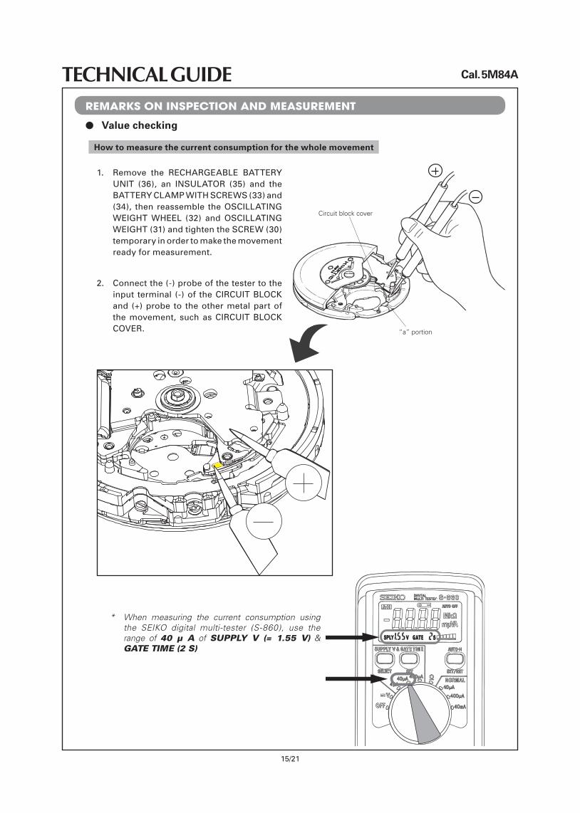
l Value checking
How to measure the current consumption for the whole movement
1. Remove the RECHARGEABLE BATTERYUNIT (36), an INSULATOR (35) and the BATTERYCLAMPWITHSCREWS (33) and (34), then reassemble theOSCILLATINGWEIGHT WHEEL (32) and OSCILLATINGWEIGHT(31) and tighten the SCREW (30) temporary in order to make the movement ready for measurement.
2. Connect the (-) probe of the tester to the input terminal (-) of the CIRCUIT BLOCK and (+)probe to theothermetalpartofthe movement, such as CIRCUIT BLOCK COVER. “a” portion
Circuit block cover
* When measuring the current consumption using the SEIKO digital multi-tester (S-860), use the range of 40 μ A of SUPPLY V (= 1.55 V) & GATE TIME (2 S)
Cal. 5M84A
16/21
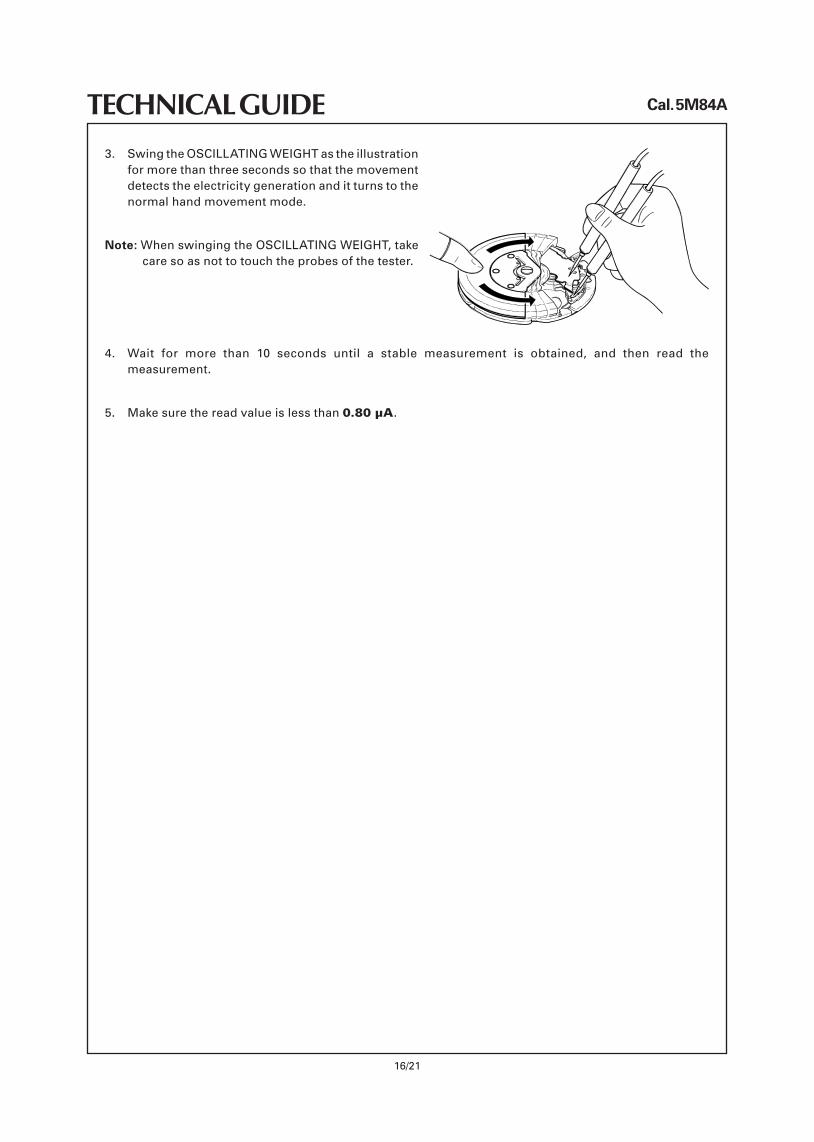
TECHNICAL GUIDE3. SwingtheOSCILLATINGWEIGHTas the illustration
for more than three seconds so that the movement detects the electricity generation and it turns to the normal hand movement mode.
Note: When swinging the OSCILLATINGWEIGHT,takecare so as not to touch the probes of the tester.
4. Wait for more than 10 seconds until a stable measurement is obtained, and then read themeasurement.
5. Make sure the read value is less than 0.80 μA.
Cal. 5M84A
17/21
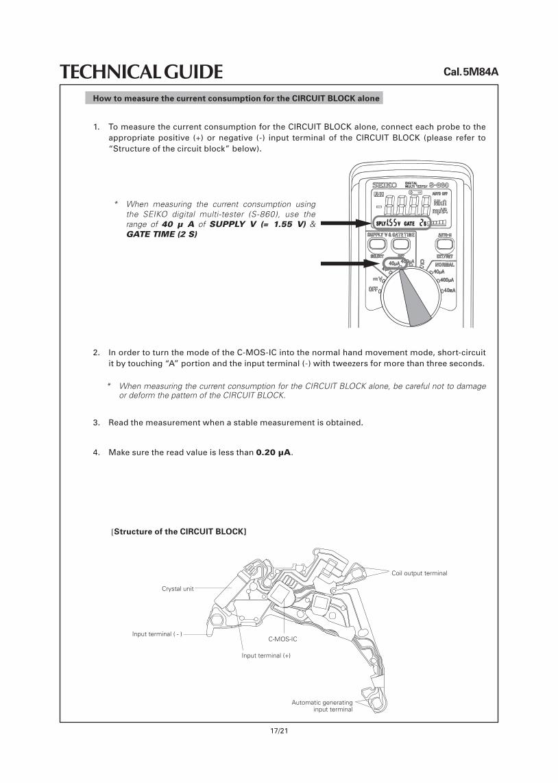
TECHNICAL GUIDEHow to measure the current consumption for the CIRCUIT BLOCK alone
[Structure of the CIRCUIT BLOCK]
Coil output terminal
Crystal unit
Input terminal ( - )C-MOS-IC
Input terminal (+)
Automatic generating input terminal
1. To measure the current consumption for the CIRCUIT BLOCKalone,connecteachprobetotheappropriate positive (+) or negative (-) input terminal of the CIRCUIT BLOCK (please refer to “Structureofthecircuitblock”below).
* When measuring the current consumption using the SEIKO digital multi-tester (S-860), use the range of 40 μ A of SUPPLY V (= 1.55 V) & GATE TIME (2 S)
2. InordertoturnthemodeoftheC-MOS-ICintothenormalhandmovementmode,short-circuititbytouching“A”portionandtheinputterminal(-)withtweezersformorethanthreeseconds.
* When measuring the current consumption for the CIRCUIT BLOCK alone, be careful not to damage or deform the pattern of the CIRCUIT BLOCK.
3. Read the measurement when a stable measurement is obtained.
4. Makesurethereadvalueislessthan0.20 μA.
Cal. 5M84A
18/21
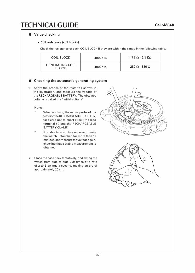
TECHNICAL GUIDEl Value checking
• Coilresistance(coilblocks)
Check the resistance of each COIL BLOCK if they are within the range in the following table.
COIL BLOCK 4002516 1.7 KΩ - 2.1 KΩ
GENERATINGCOILBLOCK 4002514 280 Ω - 380 Ω
l Checking the automatic generating system
1. Apply the probes of the tester as shown in the illustration, and measure the voltage ofthe RECHARGEABLEBATTERY. The obtained voltageiscalledthe“initialvoltage”.
Notes:
* When applying the minus probe of the tester to the RECHARGEABLEBATTERY,take care not to short-circuit the lead terminal (-) and the RECHARGEABLEBATTERYCLAMP.
* If a short-circuit has occurred, leavethe watch untouched for more than 10 minutes,andmeasurethevoltageagain,checking that a stable measurement is obtained.
2. Closethecasebacktentatively,andswingthewatch from side to side 200 times at a rate of2 to3swingsasecond,makinganarcofapproximately 20 cm.
Cal. 5M84A
19/21
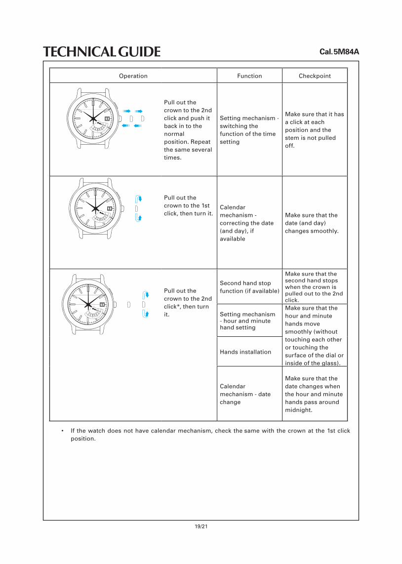
TECHNICAL GUIDEOperation Function Checkpoint
MONTUEWED
THUFRI
SATSUN
Pull out the crown to the 2nd click and push it back in to the normal position. Repeat the same several times.
Settingmechanism-switching the function of the time setting
Make sure that it has a click at each position and the stem is not pulled off.
MONTUEWED
THUFRI
SATSUN
Pull out the crown to the 1st click,thenturnit.
Calendar mechanism - correcting the date (andday),ifavailable
Make sure that the date (and day) changes smoothly.
MONTUEWED
THUFRI
SATSUN
Pull out the crown to the 2nd click*,thenturnit.
Secondhandstopfunction (if available)
Make sure that the second hand stops when the crown is pulled out to the 2nd click.
Settingmechanism- hour and minute hand setting
Make sure that the hour and minute hands move smoothly (without touching each other or touching the surface of the dial or inside of the glass).
Handsinstallation
Calendar mechanism - date change
Make sure that the date changes when the hour and minute hands pass around midnight.
• If thewatchdoesnothavecalendarmechanism,check theモsame with the crown at the 1st click position.
Cal. 5M84A
20/21
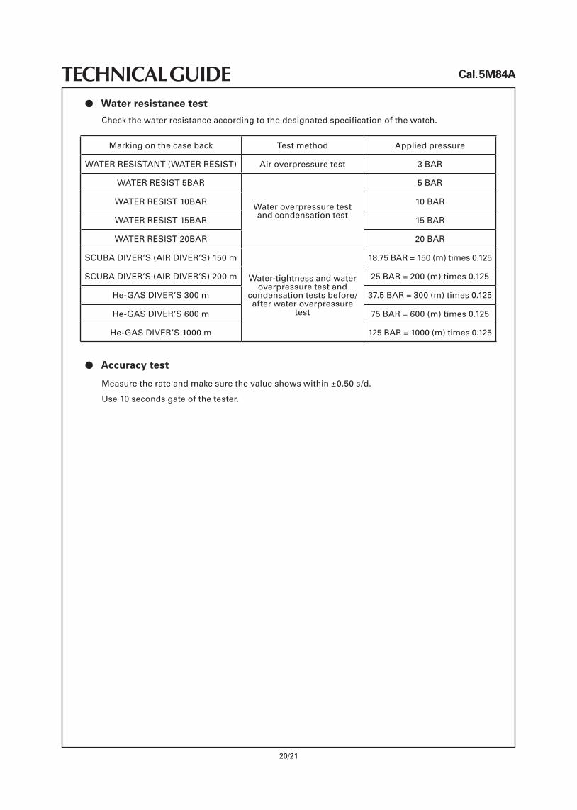
TECHNICAL GUIDEl Water resistance test
l Accuracy test
Checkthewaterresistanceaccordingtothedesignatedspecificationofthewatch.
Measure the rate and make sure the value shows within ±0.50 s/d.
Use 10 seconds gate of the tester.
Marking on the case back Test method Applied pressure
WATERRESISTANT(WATERRESIST) Air overpressure test 3 BAR
WATERRESIST5BAR
Water overpressure test and condensation test
5 BAR
WATERRESIST10BAR 10 BAR
WATERRESIST15BAR 15 BAR
WATERRESIST20BAR 20 BAR
SCUBADIVER’S(AIRDIVER’S)150m
Water-tightness and water overpressure test and
condensation tests before/after water overpressure
test
18.75 BAR = 150 (m) times 0.125
SCUBADIVER’S(AIRDIVER’S)200m 25 BAR = 200 (m) times 0.125
He-GASDIVER’S300m 37.5 BAR = 300 (m) times 0.125
He-GASDIVER’S600m 75 BAR = 600 (m) times 0.125
He-GASDIVER’S1000m 125 BAR = 1000 (m) times 0.125
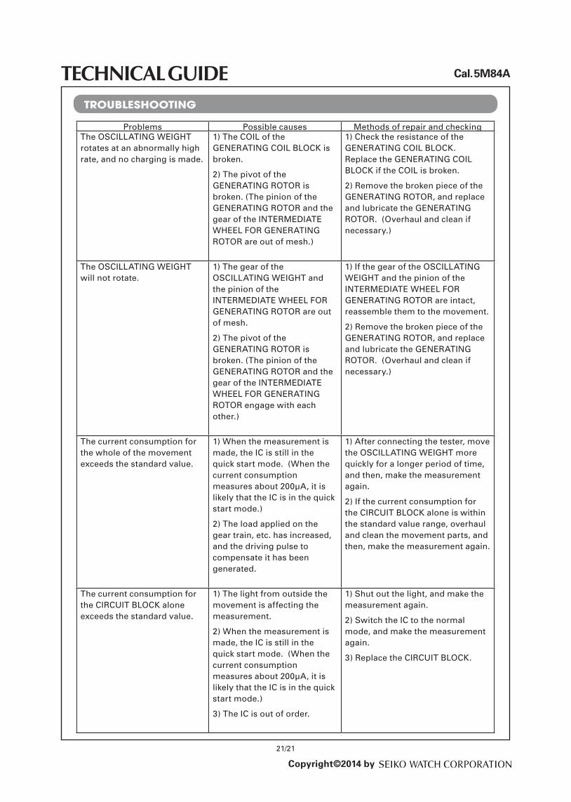
Problems Possible causes Methods of repair and checkingThe OSCILLATINGWEIGHT rotates at an abnormally high rate,andnochargingismade.
1) The COIL of the GENERATINGCOILBLOCK is broken.
2) The pivot of the GENERATINGROTOR is broken. (The pinion of the GENERATINGROTORand the gear of the INTERMEDIATEWHEELFORGENERATINGROTOR are out of mesh.)
1) Check the resistance of the GENERATINGCOILBLOCK. Replace the GENERATINGCOILBLOCK if the COIL is broken.
2) Remove the broken piece of the GENERATINGROTOR,andreplaceand lubricate the GENERATINGROTOR. (Overhaul and clean if necessary.)
The OSCILLATINGWEIGHT will not rotate.
1) The gear of the OSCILLATINGWEIGHT and the pinion of the INTERMEDIATEWHEELFORGENERATINGROTOR are out of mesh.
2) The pivot of the GENERATINGROTOR is broken. (The pinion of the GENERATINGROTOR and the gear of theINTERMEDIATEWHEELFORGENERATINGROTOR engage with each other.)
1) If the gear of the OSCILLATINGWEIGHT and the pinion of the INTERMEDIATEWHEELFORGENERATINGROTORareintact,reassemble them to the movement.
2) Remove the broken piece of the GENERATINGROTOR,andreplaceand lubricate the GENERATINGROTOR. (Overhaul and clean if necessary.)
The current consumption for the whole of the movement exceeds the standard value.
1) When the measurement is made,theICisstillinthequickstartmode.(Whenthecurrent consumption measuresabout200μA,itislikelythattheICisinthequickstart mode.)
2) The load applied on the geartrain,etc.hasincreased,and the driving pulse to compensate it has been generated.
1)Afterconnectingthetester,movethe OSCILLATINGWEIGHT more quicklyforalongerperiodoftime,andthen,makethemeasurementagain.
2) If the current consumption for the CIRCUIT BLOCK alone is within thestandardvaluerange,overhaulandcleanthemovementparts,andthen,makethemeasurementagain.
The current consumption for the CIRCUIT BLOCK alone exceeds the standard value.
1) The light from outside the movement is affecting the measurement.
2) When the measurement is made,theICisstillinthequickstartmode.(Whenthecurrent consumption measuresabout200μA,itislikelythattheICisinthequickstart mode.)
3) The IC is out of order.
1)Shutoutthelight,andmakethemeasurement again.
2)SwitchtheICtothenormalmode,andmakethemeasurementagain.
3) Replace the CIRCUIT BLOCK.
Cal. 5M84A
21/21
TECHNICAL GUIDE
Copyright©2014 by
TROUBLESHOOTING


![PARTS CATALOGUE TECHNICAL GUIDE - Watch Guywatchguy.co.uk/technical/Seiko/272_Seiko7T62A,7T92A.pdf · PARTS CATALOGUE / TECHNICAL GUIDE [SPECIFICATIONS] Cal. No. Item 7T62A Movement](https://img.pdfslide.us/doc/110x75/5b1acd287f8b9a23258df847/parts-catalogue-technical-guide-watch-7t92apdf-parts-catalogue-technical.jpg)


![Automatic Cal. 4R35B/4R36A - Jacques de Vosjdvos.com/wp-content/uploads/2015/05/seiko-4R36.pdf · Automatic Cal. 4R35B/4R36A [SPECIFICATIONS] Item Cal. No. Loss/Gain Daily rate worn](https://img.pdfslide.us/doc/110x75/5a7a24a47f8b9a5e438cbe44/automatic-cal-4r35b4r36a-jacques-de-cal-4r35b4r36a-specifications-item-cal.jpg)


![PARTS LIST / TECHNICAL GUIDE - Seiko Nederlandjuwelier.seiko.nl/Download/techguides/02037T86A.pdf · PARTS LIST / TECHNICAL GUIDE Perpetual Calendar/Alarm Chronograph Cal. 7T86A [SPECIFICATIONS]](https://img.pdfslide.us/doc/110x75/5b9aa92b09d3f2d06f8b6438/parts-list-technical-guide-seiko-parts-list-technical-guide-perpetual.jpg)