Embed Size (px)
Citation preview
ar FoldingStockAdaptEr:For use with AR variants utilizing abuffer and action spring, including alltypes of gas systems and rifle calibersfrom 5.56 to .308
Patent 8769855
TacticalLaw
*** WARNINGS ***
Observe Safe Firearm Handling At All Times.
FIREARM MODIFICATIONS SHOULD BE PERFORMED BY A CERTIFIEDARMORER OR GUNSMITH.
Before removing or installing any part, ensure the firearm is UNLOADEDwith the SAFETY ENGAGED. Remove the source of ammunition. Checkchamber and magazine well to ensure weapon is unloaded, andthen CHECK AGAIN!
Always close stock (unfold) before firing. The AR is not designed to befired from the folded position.
To avoid accidental firing in the folded position, the SAFETY shouldALWAYS be ENGAGED BEFORE FOLDING stock and should REMAINENGAGED until stock is unfolded.
1. PREPARE FOR INSTaLLATION
*** Parts (1) and (1a)are preassembled withthe Hinge Bolt (10)and should not bedisassembled. ***
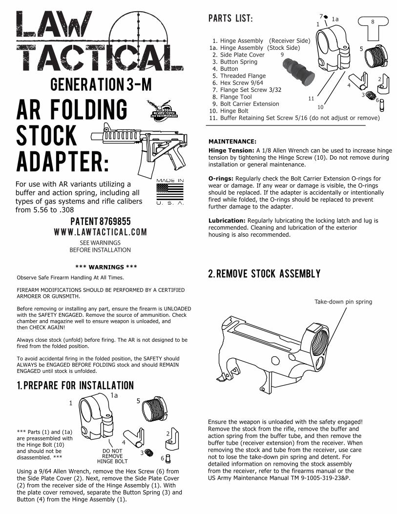
Using a 9/64 Allen Wrench, remove the Hex Screw (6) fromthe Side Plate Cover (2). Next, remove the Side Plate Cover(2) from the receiver side of the Hinge Assembly (1). Withthe plate cover removed, separate the Button Spring (3) andButton (4) from the Hinge Assembly (1).
W W W . L AW TA C T I C A L . C O M
MAINTENANCE:
Hinge Tension: A 1/8 Allen Wrench can be used to increase hingetension by tightening the Hinge Screw (10). Do not remove duringinstallation or general maintenance.
O-rings: Regularly check the Bolt Carrier Extension O-rings forwear or damage. If any wear or damage is visible, the O-ringsshould be replaced. If the adapter is accidentally or intentionallyfired while folded, the O-rings should be replaced to preventfurther damage to the adapter.
Lubrication: Regularly lubricating the locking latch and lug isrecommended. Cleaning and lubrication of the exteriorhousing is also recommended.
Parts list:
Hinge Assembly (Receiver Side) Hinge Assembly (Stock Side) Side Plate Cover Button Spring Button Threaded Flange Hex Screw 9/64 Flange Set Screw 3/32 Flange Tool Bolt Carrier Extension Hinge Bolt Buffer Retaining Set Screw 5/16 (do not adjust or remove)
11a
5
3
42
6
9
1 5
3
42
6
2. REMOVE STOCK ASSEMBLY
Ensure the weapon is unloaded with the safety engaged!Remove the stock from the rifle, remove the buffer andaction spring from the buffer tube, and then remove thebuffer tube (receiver extension) from the receiver. Whenremoving the stock and tube from the receiver, use carenot to lose the take-down pin spring and detent. Fordetailed information on removing the stock assemblyfrom the receiver, refer to the firearms manual or theUS Army Maintenance Manual TM 9-1005-319-23&P.
Take-down pin spring
Generation 3-m
SEE WARNINGSBEFORE INSTALLATION
1a
DO NOTREMOVE
HINGE BOLT
1.1a.2.3.4.5.6.7.8.9.
10.11.
87
10
11
3. INSTALL FOLDING STOCK ADAPTER
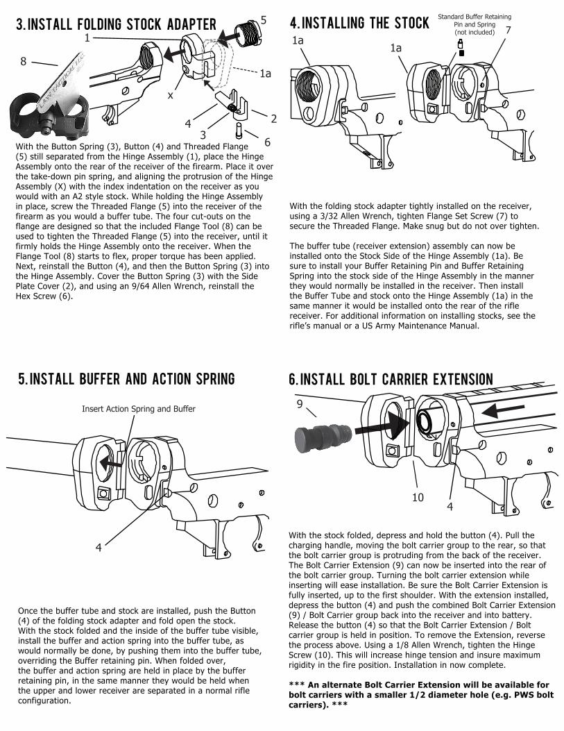
With the Button Spring (3), Button (4) and Threaded Flange(5) still separated from the Hinge Assembly (1), place the HingeAssembly onto the rear of the receiver of the firearm. Place it overthe take-down pin spring, and aligning the protrusion of the HingeAssembly (X) with the index indentation on the receiver as youwould with an A2 style stock. While holding the Hinge Assemblyin place, screw the Threaded Flange (5) into the receiver of thefirearm as you would a buffer tube. The four cut-outs on theflange are designed so that the included Flange Tool (8) can beused to tighten the Threaded Flange (5) into the receiver, until itfirmly holds the Hinge Assembly onto the receiver. When theFlange Tool (8) starts to flex, proper torque has been applied.Next, reinstall the Button (4), and then the Button Spring (3) intothe Hinge Assembly. Cover the Button Spring (3) with the SidePlate Cover (2), and using an 9/64 Allen Wrench, reinstall theHex Screw (6).
4. INSTALLING THE STOCK
With the folding stock adapter tightly installed on the receiver,using a 3/32 Allen Wrench, tighten Flange Set Screw (7) tosecure the Threaded Flange. Make snug but do not over tighten.
The buffer tube (receiver extension) assembly can now beinstalled onto the Stock Side of the Hinge Assembly (1a). Besure to install your Buffer Retaining Pin and Buffer RetainingSpring into the stock side of the Hinge Assembly in the mannerthey would normally be installed in the receiver. Then installthe Buffer Tube and stock onto the Hinge Assembly (1a) in thesame manner it would be installed onto the rear of the riflereceiver. For additional information on installing stocks, see therifle’s manual or a US Army Maintenance Manual.
1a1a
5. INSTALL BUFFER AND ACTION SPRING
Once the buffer tube and stock are installed, push the Button (4) of the folding stock adapter and fold open the stock. With the stock folded and the inside of the buffer tube visible,install the buffer and action spring into the buffer tube, as would normally be done, by pushing them into the buffer tube, overriding the Buffer retaining pin. When folded over, the buffer and action spring are held in place by the buffer retaining pin, in the same manner they would be held when the upper and lower receiver are separated in a normal rifleconfiguration.
Insert Action Spring and Buffer
4
6. INSTALL BOLT CARRIER EXTENSION
With the stock folded, depress and hold the button (4). Pull thecharging handle, moving the bolt carrier group to the rear, so thatthe bolt carrier group is protruding from the back of the receiver.The Bolt Carrier Extension (9) can now be inserted into the rear ofthe bolt carrier group. Turning the bolt carrier extension whileinserting will ease installation. Be sure the Bolt Carrier Extension isfully inserted, up to the first shoulder. With the extension installed,depress the button (4) and push the combined Bolt Carrier Extension(9) / Bolt Carrier group back into the receiver and into battery.Release the button (4) so that the Bolt Carrier Extension / Boltcarrier group is held in position. To remove the Extension, reversethe process above. Using a 1/8 Allen Wrench, tighten the HingeScrew (10). This will increase hinge tension and insure maximumrigidity in the fire position. Installation in now complete.
*** An alternate Bolt Carrier Extension will be available forbolt carriers with a smaller 1/2 diameter hole (e.g. PWS boltcarriers). ***
9
10
7
4
Standard Buffer Retaining Pin and Spring(not included)
8
5
43
6
2
1a
x
1