Embed Size (px)
Citation preview
®
01
PARTS INCLUDED
INSTALL TIME 2 HOURSINSTALL DIFFICULTY
DISCLAIMER• Raise vehicle only on jack stands or on a vehicle lift.
• Allow vehicle to cool completely prior to attempting installation.
• Do not run the engine or drive the vehicle while overheating; serious damage can occur.
• Please dispose of any liquids properly.
• Mishimoto is not responsible for any vehicle damage or personal injury due to installation errors, misuse, or removal of Mishimoto products.
• Mishimoto suggests that a trained professional install all Mishimoto products.
CAUTION Never work on the cooling system when it is hot. The coolant temperature in the radiator can be considerably higher than boiling, and the system may be under pressure. Opening a cooling system that is hot or under pressure can result in serious injury. Always wait until the system has cooled completely before servicing it in any way.
NOTEIt is recommended that you check and drain the contents of the catch cans every 1000 miles until a baseline for oil accumulation is established. This will be different for every car and will change based on ambient temperatures and driving conditions.
INSTALL PROCEDURE01. Prep the catch cans. Install the fi ttings into each catch can,
and tighten them with a 17mm wrench. The threads on these
fi ttings are tapered and may not be completely fl ush with the
can when fully installed.
02. Locate the L-shaped bracket. Remove the battery lockdown
nut closest to the washer reservoir, and install the L-shaped
bracket so that the catch can mount is on the side closest to the
oil fi ll. Then install the original lockdown nut. (1x 10mm nut)
03. Install a catch can onto this bracket so that both ports face
toward the passenger side. (2x 2.5mm bolts)
04. Remove the trim panel that runs along the passenger side
of the engine bay, next to the fender. (2x pop-clips)
CONTINUED ON FOLLOWING PAGE
2015+ SUBARU WRX BAFFLED CATCH CAN SYSTEM PARTS LIST AND INSTALLATION GUIDE
2PC | APPLICATION-SPECIFIC MOUNTING BRACKETS
2PC | BLACK, ANODIZED 6061 ALUMINUM CATCH CANS
4PC | SILICONE HOSES
4PC | PLASTIC BARBED FITTINGS
8PC | APPLICATION-SPECIFIC MOUNTING BRACKETS
4PC | BRONZE FILTERS
4PC | AIR DIVERTERS
4PC | INTERNAL BAFFLES & RODS
4PC | 3/8" NPT PLUGS
4PC | LARGE O-RINGS
MOUNTING HARDWARE
2.5MM ALLEN KEY
10MM DEEP SOCKET
1/4" DRIVE RATCHET
1/4" DRIVE 3" EXTENSION
10MM RATCHETING WRENCH
12MM DEEP SOCKET
14MM SOCKET OR WRENCH
3/8" DRIVE RATCHET
3/8" DRIVE 6" EXTENSION
FLATHEAD SCREWDRIVER
NEEDLENOSE PLIERS
SIDE-CUTTING PLIERS
TOOLS NEEDED
MISHIMOTO | 18 BOULDEN CIRCLE, NEW CASTLE, DE 19720 | P 877.466.4744 | WWW.MISHIMOTO.COM
MISHIMOTO | 18 BOULDEN CIRCLE, NEW CASTLE, DE 19720 | P 1.877.GOMISHI | WWW.MISHIMOTO.COM
®
02
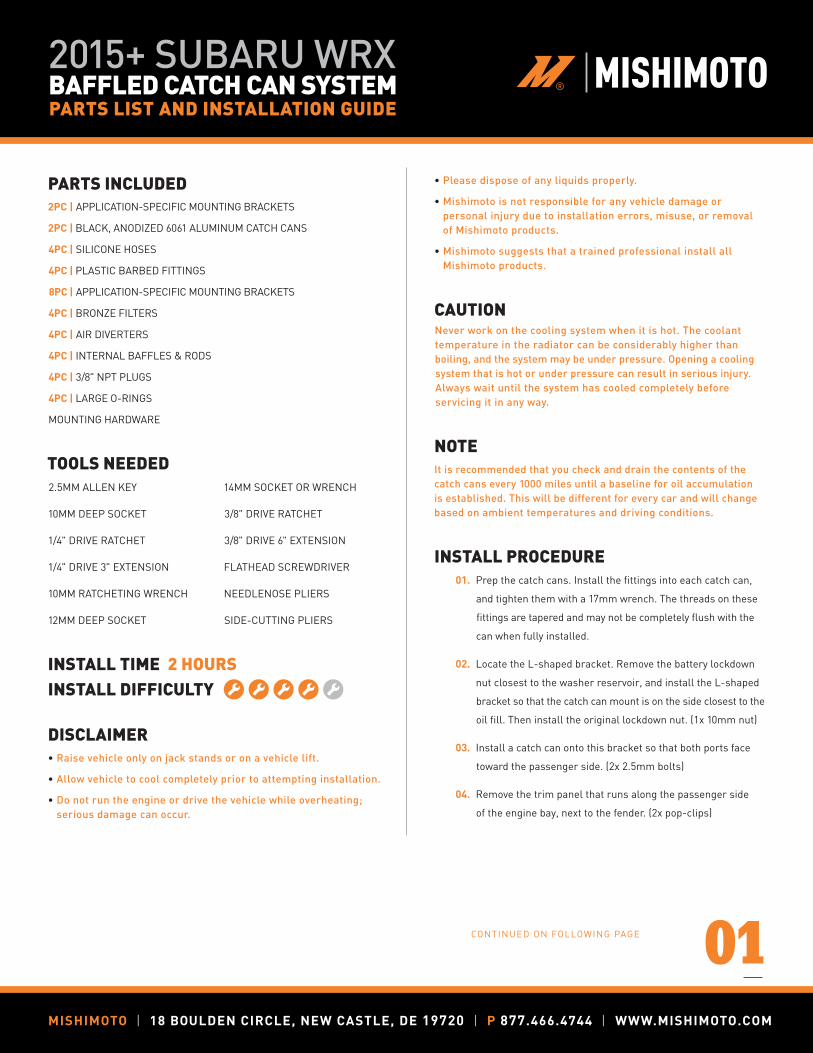
05. Locate the triangular bracket. Using the supplied hardware,
install this bracket on the passenger side of the engine bay.
The front of the bracket installs to the threaded hole that secures
the airbox; the back of the bracket installs to the open hole
near the ABS pump. Reach behind the fender to install and hold
the rear bolt while tightening. (2x 10mm bolts, 1x 10mm nut)
06. Install a catch can on this bracket so that both ports face
toward the driver side. (2x 2.5mm bolts)
07. Remove the two pop-clips that secure the back of the plastic
engine cover. Then remove the engine cover from the vehicle
by lifting it from the front edge. (2x pop-clips)
08. Remove the two pop-clips that secure the intake air duct
to the radiator support. Then remove the intake air duct.
(2x pop-clips)
09. Remove the mounting bracket that supported the front edge
of the engine cover. This bracket is secured with two bolts.
(2x 10mm bolts)
10. Note the routing of the serpentine belt, and draw a diagram
for reference. Use a 14mm socket or wrench to turn the
tensioner pulley in a clockwise direction. Then remove the
belt from the AC compressor.
11. Disconnect the wiring harness for the AC clutch.
12. Unclip the tie-downs for the alternator charge cable.
13. Unbolt the AC compressor and move it out of the way. The
engine hoist bracket will also come out. Four bolts hold in
the compressor: two behind the compressor and two below
the pulley. (4x 14mm bolts)
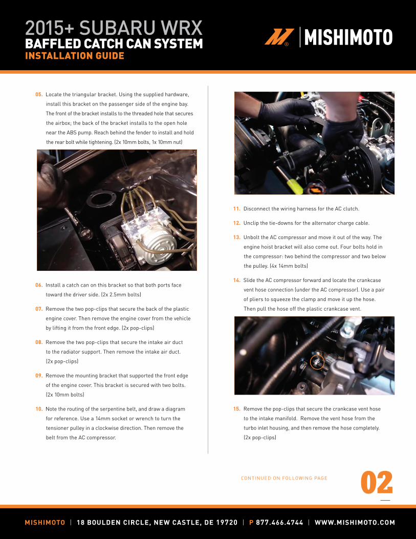
14. Slide the AC compressor forward and locate the crankcase
vent hose connection (under the AC compressor). Use a pair
of pliers to squeeze the clamp and move it up the hose.
Then pull the hose off the plastic crankcase vent.
15. Remove the pop-clips that secure the crankcase vent hose
to the intake manifold. Remove the vent hose from the
turbo inlet housing, and then remove the hose completely.
(2x pop-clips)
CONTINUED ON FOLLOWING PAGE
2015+ SUBARU WRX BAFFLED CATCH CAN SYSTEM INSTALLATION GUIDE
MISHIMOTO | 18 BOULDEN CIRCLE, NEW CASTLE, DE 19720 | P 877.466.4744 | WWW.MISHIMOTO.COM
MISHIMOTO | 18 BOULDEN CIRCLE, NEW CASTLE, DE 19720 | P 1.877.GOMISHI | WWW.MISHIMOTO.COM
®
03
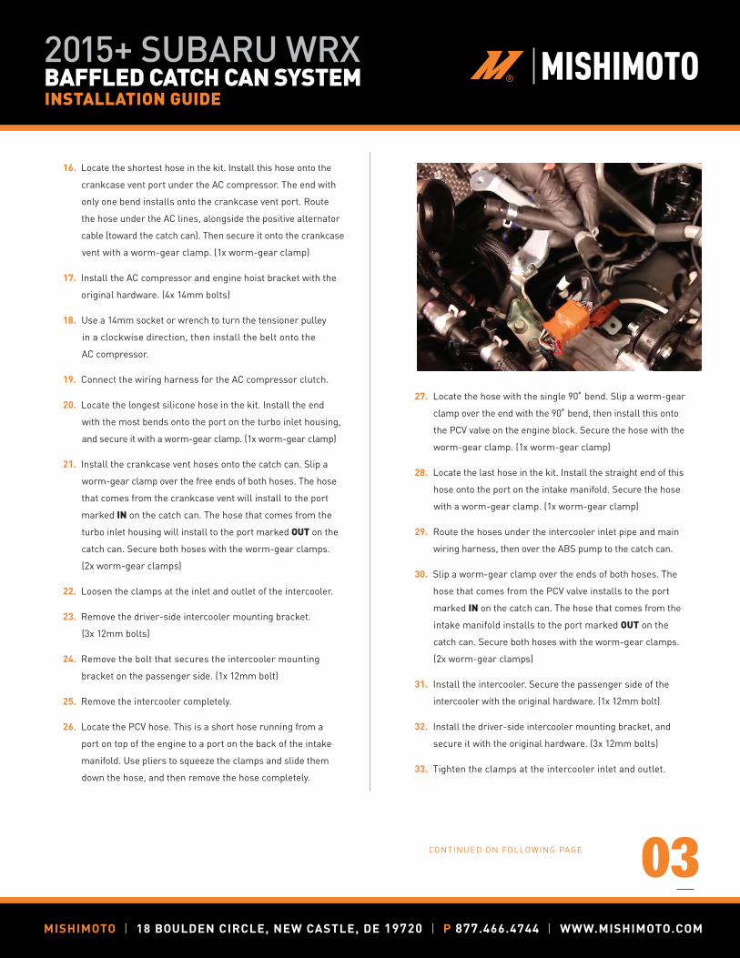
16. Locate the shortest hose in the kit. Install this hose onto the
crankcase vent port under the AC compressor. The end with
only one bend installs onto the crankcase vent port. Route
the hose under the AC lines, alongside the positive alternator
cable (toward the catch can). Then secure it onto the crankcase
vent with a worm-gear clamp. (1x worm-gear clamp)
17. Install the AC compressor and engine hoist bracket with the
original hardware. (4x 14mm bolts)
18. Use a 14mm socket or wrench to turn the tensioner pulley
in a clockwise direction, then install the belt onto the
AC compressor.
19. Connect the wiring harness for the AC compressor clutch.
20. Locate the longest silicone hose in the kit. Install the end
with the most bends onto the port on the turbo inlet housing,
and secure it with a worm-gear clamp. (1x worm-gear clamp)
21. Install the crankcase vent hoses onto the catch can. Slip a
worm-gear clamp over the free ends of both hoses. The hose
that comes from the crankcase vent will install to the port
marked IN on the catch can. The hose that comes from the
turbo inlet housing will install to the port marked OUT on the
catch can. Secure both hoses with the worm-gear clamps.
(2x worm-gear clamps)
22. Loosen the clamps at the inlet and outlet of the intercooler.
23. Remove the driver-side intercooler mounting bracket.
(3x 12mm bolts)
24. Remove the bolt that secures the intercooler mounting
bracket on the passenger side. (1x 12mm bolt)
25. Remove the intercooler completely.
26. Locate the PCV hose. This is a short hose running from a
port on top of the engine to a port on the back of the intake
manifold. Use pliers to squeeze the clamps and slide them
down the hose, and then remove the hose completely.
27. Locate the hose with the single 90̊ bend. Slip a worm-gear
clamp over the end with the 90̊ bend, then install this onto
the PCV valve on the engine block. Secure the hose with the
worm-gear clamp. (1x worm-gear clamp)
28. Locate the last hose in the kit. Install the straight end of this
hose onto the port on the intake manifold. Secure the hose
with a worm-gear clamp. (1x worm-gear clamp)
29. Route the hoses under the intercooler inlet pipe and main
wiring harness, then over the ABS pump to the catch can.
30. Slip a worm-gear clamp over the ends of both hoses. The
hose that comes from the PCV valve installs to the port
marked IN on the catch can. The hose that comes from the
intake manifold installs to the port marked OUT on the
catch can. Secure both hoses with the worm-gear clamps.
(2x worm-gear clamps)
31. Install the intercooler. Secure the passenger side of the
intercooler with the original hardware. (1x 12mm bolt)
32. Install the driver-side intercooler mounting bracket, and
secure it with the original hardware. (3x 12mm bolts)
33. Tighten the clamps at the intercooler inlet and outlet.
CONTINUED ON FOLLOWING PAGE
2015+ SUBARU WRX BAFFLED CATCH CAN SYSTEM INSTALLATION GUIDE
MISHIMOTO | 18 BOULDEN CIRCLE, NEW CASTLE, DE 19720 | P 877.466.4744 | WWW.MISHIMOTO.COM
MISHIMOTO | 18 BOULDEN CIRCLE, NEW CASTLE, DE 19720 | P 1.877.GOMISHI | WWW.MISHIMOTO.COM
®
04
34. Secure the hose that crosses over the engine to the intake
manifold, using the supplied tree-clip zip ties, and then
snip off the excess length. These zip ties will attach to the
original mounting location for the crankcase vent tube.
(2x tree-clip zip ties)
35. Install the mounting bracket for the engine cover using the
original hardware. (2x 10mm bolts)
36. Install the intake air duct. (2x pop-clips)
37. Install the engine cover and secure it with the original
hardware. (2x pop-clips)
ENJOY!
Congrats! You just fi nished installing the 2015+ Subaru WRX Baffled Catch Can System.
2015+ SUBARU WRX BAFFLED CATCH CAN SYSTEM INSTALLATION GUIDE
MISHIMOTO | 18 BOULDEN CIRCLE, NEW CASTLE, DE 19720 | P 877.466.4744 | WWW.MISHIMOTO.COM


![Duravit Spare Parts List - HM Wallace · [2] – Flush valve for 2pc toilet, Geberit HET 0074138600 85 [3] – Flush valve gasket for Geberit HET, “flapper” 1002970000 10 Extension](https://img.pdfslide.us/doc/110x75/5f37231201ea7949f2139e83/duravit-spare-parts-list-hm-wallace-2-a-flush-valve-for-2pc-toilet-geberit.jpg)