Embed Size (px)
Citation preview

Super G3 FAXBoard-AK1
oard-AK1 Rev. 0 PRINTED IN U.S.A.
Main Body PC cover A5.qxp 2/23/2012 11:39 AM Page 1
PARTSCATALOG
COPYRIGHT © 2012 CANON INC. CANON Super G3 FAX B
February 22, 2012
Rev. 0

PREFACE
This Parts Catalog contains listings of parts used
Diagrams are provided with the listings to aid the service technician in identifying clearly, the
item to be orderd.
Whenever ordering parts, consult this Parts Catalog for all of the information pertaining to each
item. Be sure to include, in the Parts Request, the full item description, the item part number,
and the quantity.
COPYRIGHT (C) 1999 CANON INC.
Use of this manual should be
strictly supervised to avoid
disclosure of confidential
information.

Contents
NUMERICAL INDEX
Super G3 FAX Board-AK1(Numerical Index) .................................... 1-1
Super G3 FAX Board-AK1(Parts Catalog)
T01 ACCESSORIES .....................................................................2-1T20 G3 FAX ASSEMBLY ..............................................................2-2T21 SPEAKER ASSEMBLY ..........................................................2-3ZZA MECHANICAL STANDARD PARTS (HOW TO USE) ...........2-4ZZB MECHANICAL STANDARD PARTS (SCREWS) ..................2-5ZZC MECHANICAL STANDARD PARTS (BOLTS) ....................2-12ZZD MECHANICAL STANDARD PARTS (NUTS) ......................2-13ZZE MECHANICAL STANDARD PARTS (RETAINING RINGS) 2-14


NUMERICAL INDEXSuper G3 FAX Board-AK1(Numerical Index)
PARTS NUMBERFIGURE
& PARTS NUMBERFIGURE
& PARTS NUMBERFIGURE
&
KEY NO. KEY NO. KEY NOFK2-0428-000 T21 - 1FK3-2452-000 T01 - 1FK3-2453-000 T01 - 1FK3-2454-000 T01 - 1FM3-2163-000 T20 - 1FM3-5580-000 T20 - 1FM4-0788-000 T20 - 3FM4-0834-000 T20 - 3FM4-0835-000 T20 - 3FM4-0838-000 T20 - 2FM4-0856-000 T20 - 2FM4-9135-000 T21 -HH2-2824-000 T01 - 2NPN T01 -NPN T20 -QK1-6441-000 T01 - 3QK1-6443-000 T01 - 4QK1-6446-000 T01 - 5QK1-6450-000 T01 - 6QK1-6455-000 T01 - 7VS1-7177-002 T20 - 4XA9-1386-000 T21 - 2
1-1


Super G3 FAX Board-AK1(PartsCatalog)
Super G3 FAX Board-AK1JP F68-0223-000
US F68-0224-000
EUR F68-0225-000
AU F68-0226-000


Contents
T01 ACCESSORIES ..................................................................................................2-1T20 G3 FAX ASSEMBLY...........................................................................................2-2T21 SPEAKER ASSEMBLY.......................................................................................2-3ZZA MECHANICAL STANDARD PARTS (HOW TO USE) ........................................2-4ZZB MECHANICAL STANDARD PARTS (SCREWS)................................................2-5ZZC MECHANICAL STANDARD PARTS (BOLTS)..................................................2-12ZZD MECHANICAL STANDARD PARTS (NUTS)....................................................2-13ZZE MECHANICAL STANDARD PARTS (RETAINING RINGS) .............................2-14

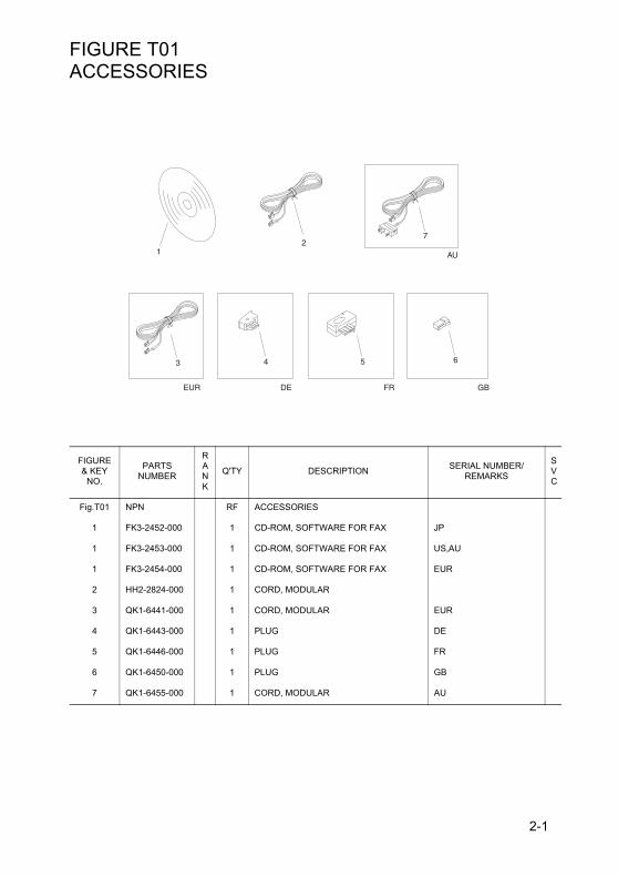
FIGURE T01
ACCESSORIESFIGURE & KEY
NO.
PARTS NUMBER
RANK
Q'TY DESCRIPTION SERIAL NUMBER/REMARKS
SVC
Fig.T01 NPN RF ACCESSORIES
1 FK3-2452-000 1 CD-ROM, SOFTWARE FOR FAX JP
1 FK3-2453-000 1 CD-ROM, SOFTWARE FOR FAX US,AU
1 FK3-2454-000 1 CD-ROM, SOFTWARE FOR FAX EUR
2 HH2-2824-000 1 CORD, MODULAR
3 QK1-6441-000 1 CORD, MODULAR EUR
4 QK1-6443-000 1 PLUG DE
5 QK1-6446-000 1 PLUG FR
6 QK1-6450-000 1 PLUG GB
7 QK1-6455-000 1 CORD, MODULAR AU
2
3 4 5 6
7
AU
EUR DE FR GB
1
2-1

FIGURE T20
G3 FAX ASSEMBLYFIGURE & KEY
NO.
PARTS NUMBER
RANK
Q'TY DESCRIPTION SERIAL NUMBER/REMARKS
SVC
Fig.T20 NPN RF G3 FAX ASSEMBLY, 1 LINE
1 FM3-5580-000 1 PSEUDO CI2 PCB ASSEMBLY JP
1 FM3-2163-000 1 OFF-HOOK DETECT PCB ASSEMBLY EXCEPT JP
2 FM4-0838-000 1 1 LINE PCB ASSEMBLY EXCEPT EUR
2 FM4-0856-000 1 1 LINE PCB ASSEMBLY EUR
3 FM4-0788-000 1 MODULAR PCB ASSEMBLY JP
3 FM4-0834-000 1 MODULAR PCB ASSEMBLY US,AU
3 FM4-0835-000 1 MODULAR PCB ASSEMBLY EUR
4 VS1-7177-002 1 CONNECTOR, SNAP TIGHT, BK
(J205)
(J28) (J29)(J17)
(J9)(J3)
(J30)
(J23)
(J15)
(J232)
(J31)
(J27)
(J37)
(J36)(J603)
(J600) (J601)(J206)
(J4)
1
2
4
3
2-2

FIGURE T21
SPEAKER ASSEMBLYFIGURE & KEY
NO.
PARTS NUMBER
RANK
Q'TY DESCRIPTION SERIAL NUMBER/REMARKS
SVC
Fig.T21 FM4-9135-000 1 SPEAKER ASSEMBLY
1 FK2-0428-000 1 SPEAKER SP1
2 XA9-1386-000 4 SCREW,RS,M3X8
(SP1)(J30)
12
2-3

FIGURE ZZA
MECHANICAL STANDARD PARTS (HOW TO USE)Table 1 Material and Surface treatment
Black
Black
Black
White
White
White
Iron and steel phosphating (P1)
6
7
8
9
Color
Black
White
White
5
Surface treatment
Stainless steel
Brass
Steel
Material
Black zinc trivalent chromate treating (BZ3)
Stainless steel black coloring (BC4)
not to be given
Regular nickel plating (NL)
Black nickel plating (BN)
White zinc trivalent chromate treating (ZC3)
Regular nickel chromium plating (NC)
Regular nickel plating (NL)
No.
1
3
4
2
Mechanical standard parts
About a mechanical standard partsA Mechanical standard parts is a mechanical part which not parts peculiar to a product.They are parts which are common to a Canon product and are used, such as a screw and a washer.The Fig No. and parts number of the mechanical standard parts are not listed in the product parts catalog.Refer to the parts catalog of mechanical standard parts when checking the parts number for screw orwasher etc. and identify them by part shape or size.
Material and surface treatment of a mechanical standard partsMaterial and surface treatment of mechanical standard parts are assigned commonly for each part.Refer to the Table 1 for the parts which material and surface treatment are assigned as numbers.
2-4

FIGURE ZZB
MECHANICAL STANDARD PARTS (SCREWS)M1.4 M1.6 M1.7 M2 M2.5 M2.62 2.4 2.5 3 3.8 4
0.5 0.55 0.5 0.6 0.9 0.82 2.4 2.5 3 3.8 4
2 2.4 2.5 3 3.8 40.48 0.55 0.58 0.73 0.85 0.93
0.68 0.8 0.88 1 1.25 1.32.5 2.8 3 3.5 4.3 4.50.8 0.85 0.9 1 1.3 1.22.5 2.8 3 3.5 4.3 4.50.5 0.55 0.5 0.6 0.9 0.8
Head size (mm)
Pan head Class 1
Countersunk head Class 1
Oval countersunk head Class 1
Pan head Class 3
Pan head Class 2
1-1. Cross Recessed Head Screws for Precision Equipments
XA1-1, 6, 7
XA1-3
XA1-4
D d
D d
LH
D d
LK H
LH
Screws
XB1-2400-609Type No. XB1-2 expresses Binding head machine screw.
Normal designation d 40 expresses M4.0.
Length L 0-60 expresses a length of 6.0mm.
Material and Surface treatment 9 expresses Steel (Black zinc trivalent chromate treating) from Table 1.
1. Screws
How to read Parts Numbers
2-5

M1.4 M1.6 M1.7 M2 M2.5 M2.62 2.4 2.5 3 3.8 4
0.5 0.55 0.5 0.6 0.9 0.8
2 2.4 2.5 3 3.8 40.5 0.55 0.5 0.6 0.9 0.8
2 2.4 2.5 3 3.8 40.48 0.55 0.58 0.73 0.85 0.93
2 2.4 2.5 3 3.8 40.48 0.55 0.58 0.73 0.85 0.93
2.5 2.8 3 3.5 4.3 4.50.5 0.55 0.5 0.6 0.9 0.8
2.5 2.8 3 3.5 4.3 4.50.8 0.85 0.9 1 1.3 1.2
2.5 2.8 3 3.5 4.3 4.50.8 0.85 0.9 1 1.3 1.2
2.5 2.8 3 - - -0.2 0.2 0.2 - - -
2.5 2.8 3 3.5 4.3 4.50.5 0.55 0.5 0.6 0.9 0.8
Head size (mm)
With tatered end pan head Class 1
With tatered end pan head Class 3
With tatered end countersunk head
With tatered end pan head Class 2
With parallel end ultra thin head
With parallel end pan head Class 1
With parallel end pan head Class 3
With parallel end countersunk head
With parallel end pan head Class 2
1-2. Precision Tapping Screws
XA4-1, 2, 4
XA4-3
XA4-5
XA4-6, 7, 9
XA4-8D d
LH
LH
LHD d
LH
D d
D d
D d
LH
2-6

M2 M2.5 M2.6 M3 M4 M53.5 4.5 4.5 5.5 7 91.3 1.7 1.7 2 2.6 3.3
4 5 - 6 8 101.2 1.45 - 1.75 2.3 2.8
4 5 - 6 8 101.6 2 - 2.45 3.2 4
8 12 12 12 16 20
4.3 5.3 5.5 6.3 8.3 10.31.2 1.5 1.6 1.9 2.5 3.1
Head size (mm)
Screw part lengthb
Pan head
Binding head
Countersunk head
Oval countersunk head
1-3. Cross Recessed Head Screws
XB1-1
XB1-2
XB1-3
XB1-4
dkdk
LkLk
dk
Lf k
dk
Lf k
2-7
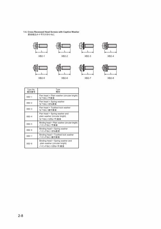
Pan head + Plain washer (circular bright)
Pan head + Spring washer
Pan head + Toothed lock washer
Pan head + Spring washer and plain washer (circular bright)
Binding head + Plain washer (circular bright)
Binding head + Spring washer
Binding head + Toothed lock washer
Binding head + Spring washer and plain washer (circular bright)
1-4. Cross Recessed Head Screws with Captive Washer
XB2-1 XB2-2 XB2-3 XB2-4
XB2-5 XB2-6 XB2-7 XB2-8
L
L
L
L
L
L
L
L
2-8

M3 M48 10
5.5 5.53.1 3.13.2 3.2
Head size (mm)
M3 M46.3 8.31.3 1.71.9 2.5
Head size (mm)
For metallic materials
For metallic materials with clawed
Binding head
1-5. Hexagon Head Tapping Screws for Matallic Materials
1-6. Special Tapping Screws
dk
L
f
k
DLHB
2-9
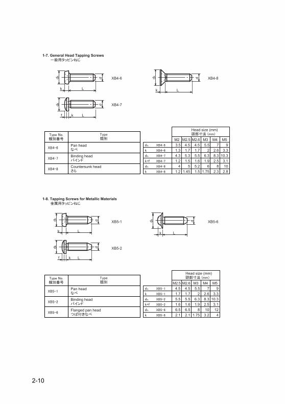
M2 M2.5 M2.6 M3 M4 M53.5 4.5 4.5 5.5 7 91.3 1.7 1.7 2 2.6 3.3
4 5 5.2 6 8 101.2 1.45 1.5 1.75 2.3 2.8
4.3 5.3 5.5 6.3 8.3 10.31.2 1.5 1.6 1.9 2.5 3.1
Head size (mm)
M2.5 M2.6 M3 M4 M54.5 4.5 5.5 7 91.7 1.7 2 2.6 3.3
6.5 6.5 8 10 122.1 2.1 1.75 3.2 4
5.5 5.5 6.3 8.3 10.31.6 1.6 1.9 2.5 3.1
Head size (mm)
Pan head
Binding head
Countersunk head
Pan head
Binding head
Flanged pan head
1-7. General Head Tapping Screws
XB4-6 XB4-8
XB4-7
1-8. Tapping Screws for Metallic Materials
XB5-1 XB5-6
XB5-2
Lk
dk ddk d
Lk
dk d
Lk
ddk
Lf k
ddk
Lf k
ddk
Lk
2-10
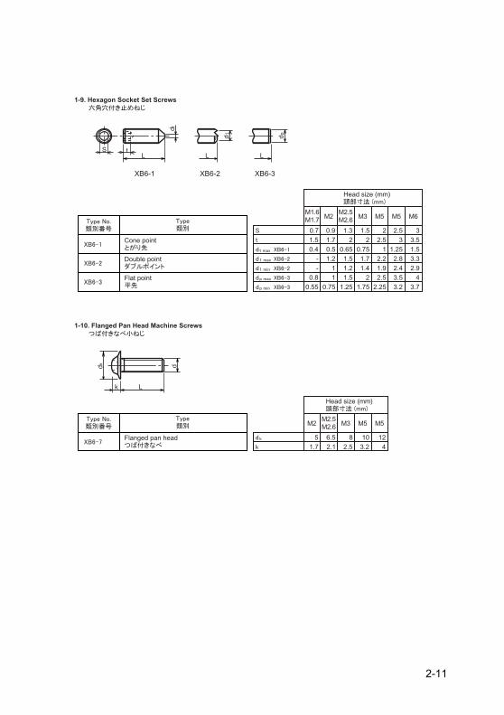
M1.6M1.7 M2
M2.5M2.6 M3 M5 M5
0.7 0.9 1.3 1.5 2 2.51.5 1.7 2 2 2.5 30.4 0.5 0.65 0.75 1 1.25
- 1 1.2 1.4 1.9 2.4- 1.2 1.5 1.7 2.2 2.8
0.8 1 1.5 2 2.5 3.5
M6
33.51.5
2.93.3
40.55 0.75 1.25 1.75 2.25 3.2 3.7
Head size (mm)
M2M2.5M2.6 M3 M5 M5
5 6.5 8 10 121.7 2.1 2.5 3.2 4
Head size (mm)
Cone point
Double point
Flat point
Flanged pan head
1-9. Hexagon Socket Set Screws
1-10. Flanged Pan Head Machine Screws
XB6-1 XB6-2 XB6-3ddk
Lk
dt
LtS
dp
L
d1
L
2-11

FIGURE ZZC
MECHANICAL STANDARD PARTS (BOLTS)max
M3 M4 M5 M6 M8 M10 M12
dk 5.5 7 8.5 10 13 16 18S 2.5 3 4 5 6 8 10
K 3 4 5 6 8 10 12Screw part length
b 2018 22 24 28 32 36
Head size (mm)
Hexagon socket head cap screws
2-1. Hexagon socket head cap screws
L
b
K
dk
S
Bolt (Socket head cap screw)
XB7-1080-409Type No. XB7-1 expresses Hexagon socket head cap screws.
Normal designation d 080 expresses M8.0.
Length L 40 expresses a length of 40mm.
Material and Surface treatment 9 expresses Steel (Black zinc trivalent chromate treating) from Table 1.
2. Bolts (Socket head cap screw)
How to read Parts Numbers
2-12
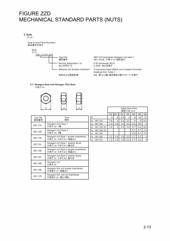
FIGURE ZZD
MECHANICAL STANDARD PARTS (NUTS)M2 M2.5 M3 M4 M5 M6 M84 5 5.5 7 8 10 13
1.6 2 2.4 3.2 4 5 6.51.2 1.6 1.8 2.4 3.2 3.6 51.6 2 2.4 3.2 4.7 5.2 6.8
- - - - 5.1 5.7 7.5- - - - 5.6 6.1 7.9
1.2 1.6 1.8 2.2 2.7 3.2 41.2 1.6 1.8 2.2 2.7 3.2 4
Head size (mm)
Hexagon nut Class 1
Hexagon nut Class 3
Hexagon nut Style 1 double chamfered
Hexagon nut Style 1 washer faced
Hexagon nut Style 2 double chamfered
Hexagon nut Style 2 washer faced
Hexagon nut
Hexagon thin nut double chamfered
Hexagon thin nut not chamfered
3-1. Hexagon Nuts and Hexagon Thin Nuts
S m m
Nuts
XB7-2100-309Type No. XB7-210 expresses Hexagon nut class 1.
Normal designation d 0-30 expresses M3.0.
Material and Surface treatment 9 expresses Steel (Black zinc trivalent chromate treating) from Table 1.
3. Nuts
How to read Parts Numbers
2-13
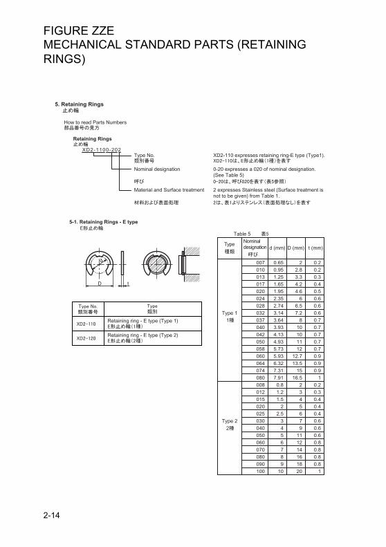
FIGURE ZZE
MECHANICAL STANDARD PARTS (RETAINING RINGS)Nominal designationType
Table 5
d (mm) t (mm)
007 0.65 2 0.2010 0.95 2.8 0.2013 1.25 3.3 0.3017 1.65 4.2 0.4020 1.95 4.6 0.5024 2.35 6 0.6028 2.74 6.5 0.6032Type 1 3.14 7.2 0.60371
Type 22
3.64 8 0.7040042050058060064074080008012015020025030040050060070080090100
3.934.134.935.735.936.327.317.91
0.81.21.5
22.5
3456789
10
10101112
12.713.5
1516.5
2345679
111214161820
0.70.70.70.70.90.90.9
10.20.30.40.40.40.60.60.60.80.80.80.8
1
D (mm)
Retaining ring - E type (Type 1)
Retaining ring - E type (Type 2)
5-1. Retaining Rings - E type
D t
d
Retaining Rings
XD2-1100-202Type No. XD2-110 expresses retaining ring-E type (Type1).
Nominal designation 0-20 expresses a 020 of nominal designation.(See Table 5)
5. Retaining Rings
How to read Parts Numbers
Material and Surface treatment 2 expresses Stainless steel (Surface treatment is not to be given) from Table 1.
2-14

Nominal designation
Table 5
d3 (mm) b (mm) a (mm) d0 (mm)
020 1.9 0.5 1 1.8 0.81.9 0.91.9 0.9
2 0.92.8 1.22.9 1.32.9 1.33.1 1.43.3 1.43.5 1.44.7 1.54.7 2
025 2.35 0.5 1.2030 2.85 0.6 1.4035 3.3 0.6 1.6040 3.8 0.8 1.8045 4.25 0.8 2050 4.75 0.8 2.2060 5.7 1 2.4070 6.7 1 2.7080090100
7.78.659.65
11.21.2
33.33.5
t (mm)
Nominal designation
No ofteeth
Table 5
d2 (mm) t (mm)
015 1.4 5.2 0.250.250.250.250.250.250.250.250.25
333445556
020 1.9 6024 2.3 6.4030 2.8 8040 3.8 9050 4.8 10060 5.8 11080 7.8 13100 9.8 15.4
D (mm)
Grip ring
Toothed retaining ring
5-2. Grip Rings
5-3. Toothed Retaining Rings
D t
d2d0
ba
d3
t
2-15
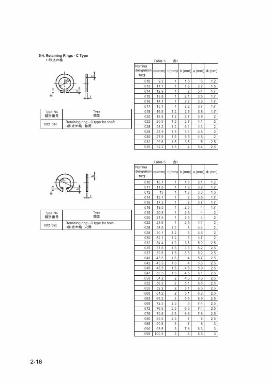
Nominal designation
Table 5
d3 (mm) b (mm) a (mm) d0 (mm)
010 9.3 111111
1.2
1.6 3 1.23.2 1.53.4 1.73.5 1.73.6 1.73.7 1.73.8 1.73.9 24.1 24.3 24.6 24.8
55.4
22.52.5
012 11.1 1.8014 12.9 2015 13.8 2.1016 14.7 2.2017 15.7 2.2018 16.5 2.6020 18.5 1.2 2.7
20.5 1.2 2.7022025028030032035
23.225.927.929.632.2
1.21.51.51.51.5
3.13.13.53.5
4
t (mm)
Nominal designation
Table 5
d3 (mm) b (mm) a (mm) d0 (mm)
010 10.7 1111111
1.8 3.1 1.23.2 1.23.3 1.53.6 1.73.7 1.7
4 1.74 24 2
4.1 24.4 24.6 24.75.25.25.25.75.85.96.16.56.56.56.86.97.47.47.8
88
8.38.5
22.52.52.52.52.52.52.52.52.52.52.52.52.52.52.52.5
333
011 11.8 1.8012 13 1.8014 15.1 2016 17.3 2018 19.5 2.5019020
20.5 2.5
02221.5 1 2.523.5 1 2.5
025028030032035037040042045047050052055060062068072075080085090095
26.930.132.134.437.839.843.545.548.550.554.256.259.264.266.272.576.579.585.590.595.5
100.5
1.21.21.21.21.51.51.81.81.81.8
22222
2.52.52.52.5
333
333
3.53.53.5
44
4.54.54.55.15.15.15.5
66.66.6
77
7.68
t (mm)
Retaining ring - C type for shaft
Retaining ring - C type for hole
5-4. Retaining Rings - C Type
t
d3
b
a
d0
t
d3
b
a
d0
2-16

Prepared by
CANON INC.
OIP Business Support Group