Embed Size (px)
Citation preview
Check out updated information at www.AFRplus.com
Dobeck Performance ∙ 157 Progressive Drive, Belgrade, MT 59714 USA ∙ Mon-Fri 8am-5pm MST PH: (406)-388-2377 ∙ Toll Free: (877) 764-3337 ∙ Fax: 406-388-2455 ∙ [email protected]
PARTS LIST
AFR GAUGE
WIDEBAND CONTROLLER
BOSCH O2 SENSOR
INSTRUCTIONS SET
ZIP TIES
VELCRO PATCH
DASH MOUNTING BRACKET
The following parts may or may not be
included as it depends on application:
OXYGEN SENSOR BYPASSES
O2 SENSOR EXHAUST BUNG
The following may be purchased
separately:
HANDLE BAR MOUNTING
USB TO IRDA ADAPTER
POWERLAB ACCOUNT
PLEASE READ ALL INSTRUCTIONS BEFORE STARTING INSTALLATION. BE SURE YOUR VEHICLE’S ENGINE IS COLD. IMPORTANT – PLEASE READ CAREFULLY The AFR+ is legal ONLY for closed course vehicles. The AFR+ is not applicable, nor intended for use on emissions controlled street, highway or off-road vehicles. The AFR+ is not applicable, nor intended for use on aircraft.
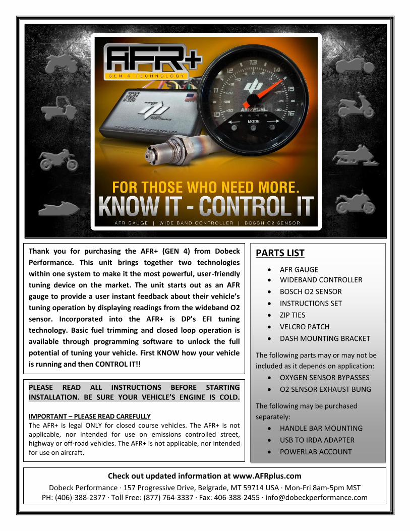
Thank you for purchasing the AFR+ (GEN 4) from Dobeck
Performance. This unit brings together two technologies
within one system to make it the most powerful, user-friendly
tuning device on the market. The unit starts out as an AFR
gauge to provide a user instant feedback about their vehicle’s
tuning operation by displaying readings from the wideband O2
sensor. Incorporated into the AFR+ is DP’s EFI tuning
technology. Basic fuel trimming and closed loop operation is
available through programming software to unlock the full
potential of tuning your vehicle. First KNOW how your vehicle
is running and then CONTROL IT!!
GENERAL LAYOUT EXPLANATIONS_______________________________
GENERAL TERMINOLOGY EXPLANATIONS__________________________
Air Fuel Ratio (AFR) - The most common reference term used for mixtures in internal combustion engines. It is the ratio between the mass of air and the mass of fuel in the air-fuel mix at any given moment.
Oxygen (O2) sensor - Is an electronic device that measures the proportion of oxygen (O2) in the exhaust gas.
Wideband vs Narrowband sensors – A narrowband O2 sensor is only calibrated to know whether the current AFR is rich, lean, or stoich. A wideband O2 sensor is much more sophisticated and can supply the exact AFR measurement across a wide range of possible AFR values.
Load - Is the measurement of how hard an engine is working. Coasting downhill is considered very low load. Driving uphill is considered high load. DP’s EFI tuning technology is a load based system.
Open loop vs Closed loop – Different operations both the stock ECU and the AFR+ can function under independently. Open loop means NO fuel trimming is occurring based on the O2 sensor signal. Closed loop is using the O2 sensor input signal to react rapidly to the changing conditions and make fuel trims to match the desired air/fuel mixture.
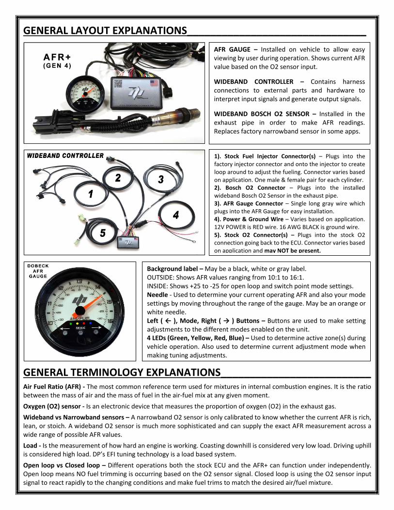
AFR GAUGE – Installed on vehicle to allow easy viewing by user during operation. Shows current AFR value based on the O2 sensor input.
WIDEBAND CONTROLLER – Contains harness connections to external parts and hardware to interpret input signals and generate output signals.
WIDEBAND BOSCH O2 SENSOR – Installed in the exhaust pipe in order to make AFR readings. Replaces factory narrowband sensor in some apps.
1). Stock Fuel Injector Connector(s) – Plugs into the factory injector connector and onto the injector to create loop around to adjust the fueling. Connector varies based on application. One male & female pair for each cylinder. 2). Bosch O2 Connector – Plugs into the installed wideband Bosch O2 Sensor in the exhaust pipe. 3). AFR Gauge Connector – Single long gray wire which plugs into the AFR Gauge for easy installation. 4). Power & Ground Wire – Varies based on application. 12V POWER is RED wire. 16 AWG BLACK is ground wire. 5). Stock O2 Connector(s) – Plugs into the stock O2 connection going back to the ECU. Connector varies based on application and may NOT be present.
Background label – May be a black, white or gray label. OUTSIDE: Shows AFR values ranging from 10:1 to 16:1. INSIDE: Shows +25 to -25 for open loop and switch point mode settings. Needle - Used to determine your current operating AFR and also your mode settings by moving throughout the range of the gauge. May be an orange or white needle. Left ( ← ), Mode, Right ( → ) Buttons – Buttons are used to make setting adjustments to the different modes enabled on the unit. 4 LEDs (Green, Yellow, Red, Blue) – Used to determine active zone(s) during vehicle operation. Also used to determine current adjustment mode when making tuning adjustments.
General Operating Instructions__________________________________
The AFR+ can be adjusted “on the fly” to tune your vehicle. No computer or other external device is needed to make tuning adjustments. All that is required is for your vehicle to be RUNNING which provides power to the unit. It is recommended to install the AFR+ and take a test ride first before making any mode adjustments. ADJUSTING THE FUEL ZONES WHILE DRIVING IS NOT RECOMMENDED. DO NOT SIMPLY TURN THE KEY ON.
Startup – When you start your vehicle the LEDs will scroll back and forth for several seconds. The needle may sweep across the entire gauge and back, but will stay at one side of the gauge. After a period of time the needle will then move to a position which is displaying the current AFR value. The time period varies based on how warm the engine is on your vehicle. When one LED is being displayed and the needle is displaying an AFR value then you are ready to ride.
Adjustment Modes – Six modes are available to make adjustments. You enter the adjustment mode by pressing the MODE button on the AFR gauge. Correctly entering the adjustment mode should display a flashing GREEN LED on the LED display. Pressing the MODE button repetitively will move you through all the modes. Take note that the MODE button is sensitive and will at times skip a mode. Pressing the MODE button at the last mode will bring you back to the first mode. To exit the adjustment mode and return to operation mode you just wait five seconds until the LED display reverts back to a solid LED color.
The six modes available are distinguished by an LED color combination. The six modes in respective order are as follows: Green, Yellow, Red, Green-Blue, Yellow-Blue, and Red-Blue. All six modes can be set to their own setting. The settings are adjusted by pressing the LEFT () and RIGHT () buttons. Modes 4, 5 and 6 are distinguished by the BLUE LED also flashing along with the corresponding mode color.
Every mode represents an adjustable feature within your vehicle’s drive cycle. Reference the Example Drive Cycle diagram to gain a visual understanding. Each mode can be defined as either a FUELING or SWITCH POINT mode:
FUELING MODES - Modify the fuel amount compared to the stock fuel when the corresponding zone is active. Pressing the Right () button will lean out the AFR and pressing the Left () button will richen the AFR. Fueling modes can be closed loop or open loop. For OPEN LOOP modes use the INSIDE +25 to -25 numbers to reference. For CLOSED LOOP modes use the OUTSIDE AFR values to set the value the system will actually target for fueling.
SWITCH POINT MODES – Determine the transition point between two corresponding zones. The higher the setting the longer it takes for a zone to engage. The lower the setting the faster a zone will engage. Switch point modes do not have to be adjusted that frequently. Use the INSIDE +25 to -25 numbers to reference the mode setting.
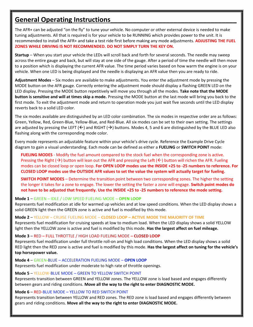
Mode 1 – GREEN – IDLE / LOW SPEED FUELING MODE – OPEN LOOP Represents fuel modification at idle for warmed up vehicles and at low speed conditions. When the LED display shows a solid GREEN light then the GREEN zone is active and fuel is modified by this mode.
Mode 2 – YELLOW – CRUISE FUELING MODE – CLOSED LOOP – ACTIVE MODE THE MAJORITY OF TIME Represents fuel modification for cruising speeds at low to medium load. When the LED display shows a solid YELLOW light then the YELLOW zone is active and fuel is modified by this mode. Has the largest affect on fuel mileage.
Mode 3 – RED – FULL THROTTLE / HIGH LOAD FUELING MODE – CLOSED LOOP Represents fuel modification under full throttle roll-on and high load conditions. When the LED display shows a solid RED light then the RED zone is active and fuel is modified by this mode. Has the largest affect on tuning for the vehicle’s top horsepower value.
Mode 4 – GREEN-BLUE – ACCELERATION FUELING MODE – OPEN LOOP Represents fuel modification under moderate to high rate of throttle openings.
Mode 5 – YELLOW-BLUE MODE – GREEN TO YELLOW SWITCH POINT Represents transition between GREEN and YELLOW zones. The YELLOW zone is load based and engages differently between gears and riding conditions. Move all the way to the right to enter DIAGNOSTIC MODE.
Mode 6 – RED-BLUE MODE – YELLOW TO RED SWITCH POINT Represents transition between YELLOW and RED zones. The RED zone is load based and engages differently between gears and riding conditions. Move all the way to the right to enter DIAGNOSTIC MODE.
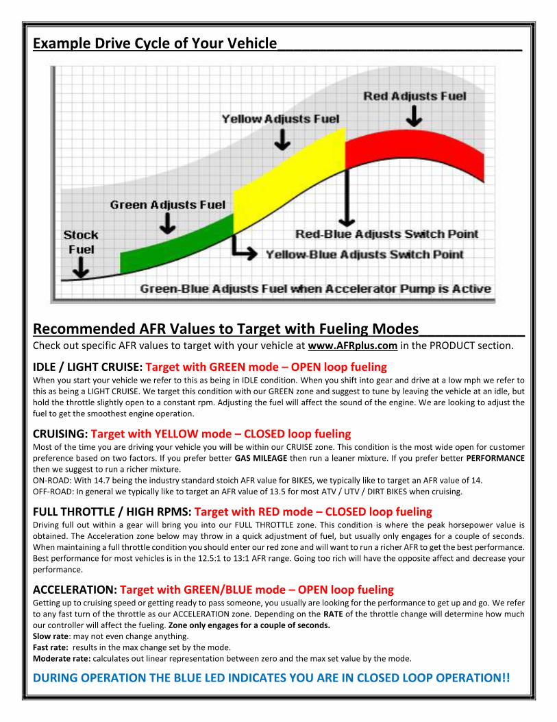
Example Drive Cycle of Your Vehicle______________________________
Recommended AFR Values to Target with Fueling Modes_____________ Check out specific AFR values to target with your vehicle at www.AFRplus.com in the PRODUCT section.
IDLE / LIGHT CRUISE: Target with GREEN mode – OPEN loop fueling When you start your vehicle we refer to this as being in IDLE condition. When you shift into gear and drive at a low mph we refer to this as being a LIGHT CRUISE. We target this condition with our GREEN zone and suggest to tune by leaving the vehicle at an idle, but hold the throttle slightly open to a constant rpm. Adjusting the fuel will affect the sound of the engine. We are looking to adjust the fuel to get the smoothest engine operation.
CRUISING: Target with YELLOW mode – CLOSED loop fueling Most of the time you are driving your vehicle you will be within our CRUISE zone. This condition is the most wide open for customer preference based on two factors. If you prefer better GAS MILEAGE then run a leaner mixture. If you prefer better PERFORMANCE then we suggest to run a richer mixture. ON-ROAD: With 14.7 being the industry standard stoich AFR value for BIKES, we typically like to target an AFR value of 14. OFF-ROAD: In general we typically like to target an AFR value of 13.5 for most ATV / UTV / DIRT BIKES when cruising.
FULL THROTTLE / HIGH RPMS: Target with RED mode – CLOSED loop fueling Driving full out within a gear will bring you into our FULL THROTTLE zone. This condition is where the peak horsepower value is obtained. The Acceleration zone below may throw in a quick adjustment of fuel, but usually only engages for a couple of seconds. When maintaining a full throttle condition you should enter our red zone and will want to run a richer AFR to get the best performance. Best performance for most vehicles is in the 12.5:1 to 13:1 AFR range. Going too rich will have the opposite affect and decrease your performance.
ACCELERATION: Target with GREEN/BLUE mode – OPEN loop fueling Getting up to cruising speed or getting ready to pass someone, you usually are looking for the performance to get up and go. We refer to any fast turn of the throttle as our ACCELERATION zone. Depending on the RATE of the throttle change will determine how much our controller will affect the fueling. Zone only engages for a couple of seconds. Slow rate: may not even change anything. Fast rate: results in the max change set by the mode. Moderate rate: calculates out linear representation between zero and the max set value by the mode.
DURING OPERATION THE BLUE LED INDICATES YOU ARE IN CLOSED LOOP OPERATION!!
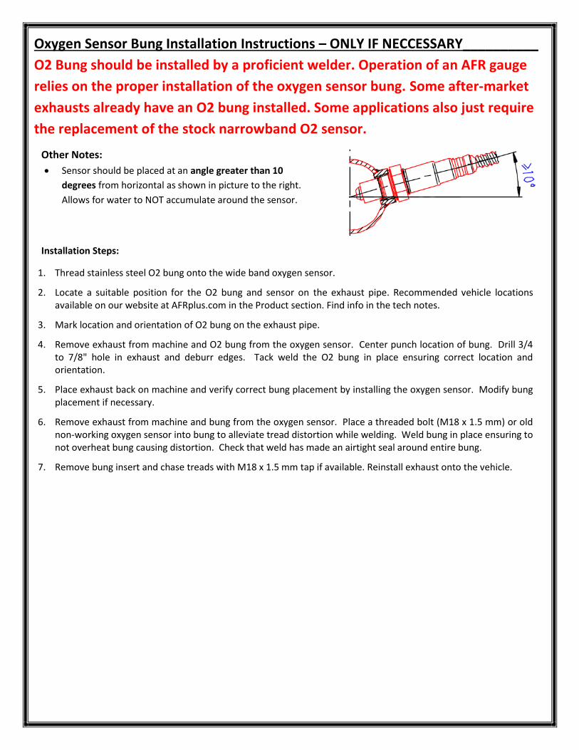
Oxygen Sensor Bung Installation Instructions – ONLY IF NECCESSARY__________
O2 Bung should be installed by a proficient welder. Operation of an AFR gauge
relies on the proper installation of the oxygen sensor bung. Some after-market
exhausts already have an O2 bung installed. Some applications also just require
the replacement of the stock narrowband O2 sensor.
Installation Steps:
1. Thread stainless steel O2 bung onto the wide band oxygen sensor.
2. Locate a suitable position for the O2 bung and sensor on the exhaust pipe. Recommended vehicle locations available on our website at AFRplus.com in the Product section. Find info in the tech notes.
3. Mark location and orientation of O2 bung on the exhaust pipe.
4. Remove exhaust from machine and O2 bung from the oxygen sensor. Center punch location of bung. Drill 3/4 to 7/8" hole in exhaust and deburr edges. Tack weld the O2 bung in place ensuring correct location and orientation.
5. Place exhaust back on machine and verify correct bung placement by installing the oxygen sensor. Modify bung placement if necessary.
6. Remove exhaust from machine and bung from the oxygen sensor. Place a threaded bolt (M18 x 1.5 mm) or old non-working oxygen sensor into bung to alleviate tread distortion while welding. Weld bung in place ensuring to not overheat bung causing distortion. Check that weld has made an airtight seal around entire bung.
7. Remove bung insert and chase treads with M18 x 1.5 mm tap if available. Reinstall exhaust onto the vehicle.
Other Notes:
Sensor should be placed at an angle greater than 10
degrees from horizontal as shown in picture to the right.
Allows for water to NOT accumulate around the sensor.
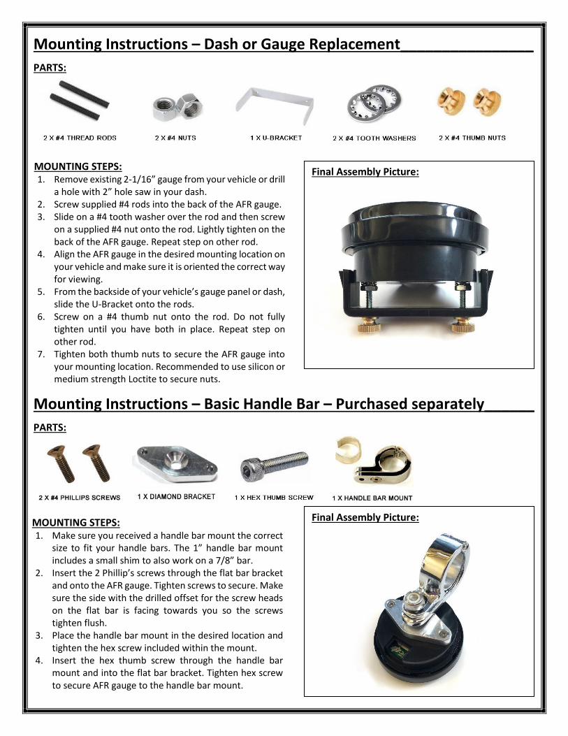
Mounting Instructions – Dash or Gauge Replacement________________
PARTS:
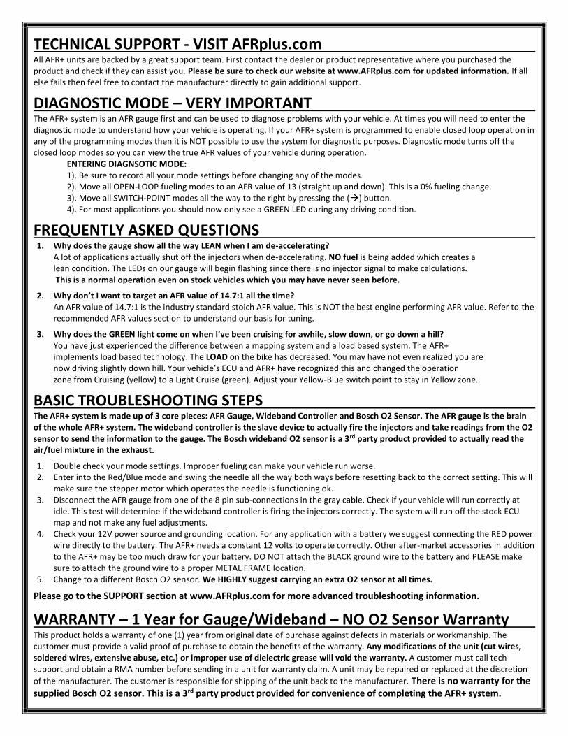
Mounting Instructions – Basic Handle Bar – Purchased separately______
PARTS:
Final Assembly Picture:
MOUNTING STEPS: 1. Remove existing 2-1/16” gauge from your vehicle or drill
a hole with 2” hole saw in your dash. 2. Screw supplied #4 rods into the back of the AFR gauge. 3. Slide on a #4 tooth washer over the rod and then screw
on a supplied #4 nut onto the rod. Lightly tighten on the back of the AFR gauge. Repeat step on other rod.
4. Align the AFR gauge in the desired mounting location on your vehicle and make sure it is oriented the correct way for viewing.
5. From the backside of your vehicle’s gauge panel or dash, slide the U-Bracket onto the rods.
6. Screw on a #4 thumb nut onto the rod. Do not fully tighten until you have both in place. Repeat step on other rod.
7. Tighten both thumb nuts to secure the AFR gauge into your mounting location. Recommended to use silicon or medium strength Loctite to secure nuts.
Final Assembly Picture:
MOUNTING STEPS: 1. Make sure you received a handle bar mount the correct
size to fit your handle bars. The 1” handle bar mount includes a small shim to also work on a 7/8” bar.
2. Insert the 2 Phillip’s screws through the flat bar bracket and onto the AFR gauge. Tighten screws to secure. Make sure the side with the drilled offset for the screw heads on the flat bar is facing towards you so the screws tighten flush.
3. Place the handle bar mount in the desired location and tighten the hex screw included within the mount.
4. Insert the hex thumb screw through the handle bar mount and into the flat bar bracket. Tighten hex screw to secure AFR gauge to the handle bar mount.
TECHNICAL SUPPORT - VISIT AFRplus.com
All AFR+ units are backed by a great support team. First contact the dealer or product representative where you purchased the product and check if they can assist you. Please be sure to check our website at www.AFRplus.com for updated information. If all else fails then feel free to contact the manufacturer directly to gain additional support.
DIAGNOSTIC MODE – VERY IMPORTANT
The AFR+ system is an AFR gauge first and can be used to diagnose problems with your vehicle. At times you will need to enter the diagnostic mode to understand how your vehicle is operating. If your AFR+ system is programmed to enable closed loop operation in any of the programming modes then it is NOT possible to use the system for diagnostic purposes. Diagnostic mode turns off the closed loop modes so you can view the true AFR values of your vehicle during operation. ENTERING DIAGNSOTIC MODE: 1). Be sure to record all your mode settings before changing any of the modes. 2). Move all OPEN-LOOP fueling modes to an AFR value of 13 (straight up and down). This is a 0% fueling change. 3). Move all SWITCH-POINT modes all the way to the right by pressing the () button. 4). For most applications you should now only see a GREEN LED during any driving condition.
FREQUENTLY ASKED QUESTIONS
1. Why does the gauge show all the way LEAN when I am de-accelerating? A lot of applications actually shut off the injectors when de-accelerating. NO fuel is being added which creates a lean condition. The LEDs on our gauge will begin flashing since there is no injector signal to make calculations. This is a normal operation even on stock vehicles which you may have never seen before.
2. Why don’t I want to target an AFR value of 14.7:1 all the time? An AFR value of 14.7:1 is the industry standard stoich AFR value. This is NOT the best engine performing AFR value. Refer to the recommended AFR values section to understand our basis for tuning.
3. Why does the GREEN light come on when I’ve been cruising for awhile, slow down, or go down a hill? You have just experienced the difference between a mapping system and a load based system. The AFR+ implements load based technology. The LOAD on the bike has decreased. You may have not even realized you are now driving slightly down hill. Your vehicle’s ECU and AFR+ have recognized this and changed the operation zone from Cruising (yellow) to a Light Cruise (green). Adjust your Yellow-Blue switch point to stay in Yellow zone.
BASIC TROUBLESHOOTING STEPS
The AFR+ system is made up of 3 core pieces: AFR Gauge, Wideband Controller and Bosch O2 Sensor. The AFR gauge is the brain of the whole AFR+ system. The wideband controller is the slave device to actually fire the injectors and take readings from the O2 sensor to send the information to the gauge. The Bosch wideband O2 sensor is a 3rd party product provided to actually read the air/fuel mixture in the exhaust.
1. Double check your mode settings. Improper fueling can make your vehicle run worse. 2. Enter into the Red/Blue mode and swing the needle all the way both ways before resetting back to the correct setting. This will
make sure the stepper motor which operates the needle is functioning ok. 3. Disconnect the AFR gauge from one of the 8 pin sub-connections in the gray cable. Check if your vehicle will run correctly at
idle. This test will determine if the wideband controller is firing the injectors correctly. The system will run off the stock ECU map and not make any fuel adjustments.
4. Check your 12V power source and grounding location. For any application with a battery we suggest connecting the RED power wire directly to the battery. The AFR+ needs a constant 12 volts to operate correctly. Other after-market accessories in addition to the AFR+ may be too much draw for your battery. DO NOT attach the BLACK ground wire to the battery and PLEASE make sure to attach the ground wire to a proper METAL FRAME location.
5. Change to a different Bosch O2 sensor. We HIGHLY suggest carrying an extra O2 sensor at all times.
Please go to the SUPPORT section at www.AFRplus.com for more advanced troubleshooting information.
WARRANTY – 1 Year for Gauge/Wideband – NO O2 Sensor Warranty
This product holds a warranty of one (1) year from original date of purchase against defects in materials or workmanship. The customer must provide a valid proof of purchase to obtain the benefits of the warranty. Any modifications of the unit (cut wires, soldered wires, extensive abuse, etc.) or improper use of dielectric grease will void the warranty. A customer must call tech support and obtain a RMA number before sending in a unit for warranty claim. A unit may be repaired or replaced at the discretion
of the manufacturer. The customer is responsible for shipping of the unit back to the manufacturer. There is no warranty for the supplied Bosch O2 sensor. This is a 3rd party product provided for convenience of completing the AFR+ system.
Generic Installation Instructions – Visit www.AFRplus.com for Advanced
1. You should now have the correct size O2 bung in your exhaust pipe before going any further. Some applications may simply replace a factory narrowband O2 sensor which was already the correct size. The O2 bung needs to be 18mm to allow fitment of the O2 sensor. Check out www.AFRplus.com for specific vehicle information.
2. Install the supplied Bosch wideband O2 sensor into the O2 bung on your exhaust pipe.
3. Determine where you will mount the AFR gauge. Refer to the previous Gauge Mounting section if needed. The AFR gauge may replace an existing factory gauge using the supplied mounting hardware. There are also a number of after-market mounts available for purchase online through different vendors.
4. Remove necessary vehicle parts to gain access to the fuel injectors or sub-harness. Also remove parts necessary to properly route the cabling for a clean looking installation. Please consult your user’s manual for removal procedures. Check out www.AFRplus.com for more advance information if you need assistance.
5. You are now ready to install the Wideband Controller, AFR gauge and Bosch O2 sensor. The AFR gauge connects to the single GRAY wire with a small BLACK 8 pin connector. The Bosch O2 sensor connects with the large BLACK 6 pin connector which has a GRAY hinged part to make the connection. The injector harness will vary based on your application. Each injector harness will have a male and female connector which will mate to the factory connections. Most applications plug into the fuel injectors, but some do plug into a sub-harness.
6. Determine the best location to mount the wideband controller using the supplied Velcro patch. The wideband controller does not need to be accessible. Typical mounting locations are under the seat, next to the battery, inside a side cover, etc. If possible mount the wideband controller with the wires facing down.
7. VERY FIRST CONNECTION is to attach the BLACK ground lead wire coming from the wideband controller to a PROPER METAL FRAME BOLT FOR GROUNDING. Depending on your application you will then attach the RED power lead wire to the POSITIVE side of the battery. This power wire ONLY provides 12 volts for the O2 sensor and ONLY draws power when the system recognizes the vehicle is running. The silver terminal ends can be cut open to fit around the bolt and terminal if necessary.
8. Locate fuel injector(s) on the throttle body. The throttle body is positioned between the engine and the air box. If the application has multiple injectors then there will be multiple throttle bodies. You may have to remove additional parts to access the injectors. Please consult your owner’s manual.
9. Route the injector harness as needed to go from your mounting location to the injectors. Note: Make sure to keep the harness away from hot and moving parts. Use zip ties as needed to attach to the frame.
10. Unplug factory connector from the injector. Plug the matching injector connector back onto the injector. Plug the mating connector from the wideband injector harness back into the connector you took off of the injector. Repeat steps if there are multiple injectors. Note: For multiple injector applications it USUALLY does not matter which connector pair goes to which injector, but make sure channel 1 is on the same cylinder as the installed O2 sensor. The connector with a double pinned RED wire and a YELLOW wire is the channel 1 injector pair. The MAIN 12 VOLT POWER for the system is through this connection.
11. Route the single GRAY wire for the AFR gauge up through the frame to your gauge mounting location. The GRAY wire will connect through small BLACK 8 pin connectors. Use zip ties as needed to attach to the frame.
12. Route the single BLACK harness with the large BLACK 6 pin connector to the installed Bosch wideband O2 sensor. Use zip ties as needed to attach to the frame.
13. Make sure all connections are firmly secure and allow a little slack at the connections to prevent engine vibration from damaging/breaking a wire on the harness. All parts should be mounted in a way as to not cause a handling problem with the vehicle.
14. If your vehicle is equipped with a stock narrowband sensor then you may need to insert an O2 bypass or connect a narrowband feedback harness. Check out www.AFRplus.com for specific vehicle information.
15. You are now ready to START your vehicle and make sure your AFR Gauge is operating correctly. Refer to General Operating Instructions. DO NOT SIMPLY TURN THE KEY ON FOR TROUBLESHOOTING.
16. Reassemble all parts removed during the installation.
PLEASE view installation pictures online at www.AFRplus.com in the Products section.
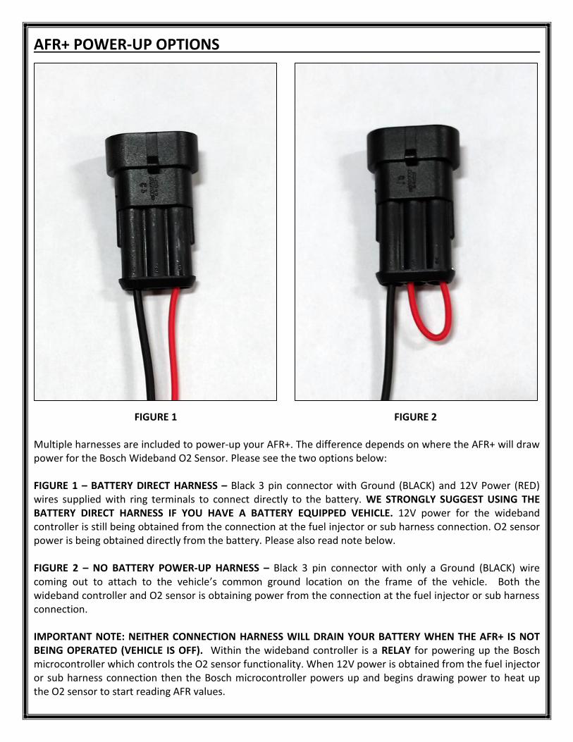
AFR+ POWER-UP OPTIONS
FIGURE 1 FIGURE 2 Multiple harnesses are included to power-up your AFR+. The difference depends on where the AFR+ will draw power for the Bosch Wideband O2 Sensor. Please see the two options below: FIGURE 1 – BATTERY DIRECT HARNESS – Black 3 pin connector with Ground (BLACK) and 12V Power (RED) wires supplied with ring terminals to connect directly to the battery. WE STRONGLY SUGGEST USING THE BATTERY DIRECT HARNESS IF YOU HAVE A BATTERY EQUIPPED VEHICLE. 12V power for the wideband controller is still being obtained from the connection at the fuel injector or sub harness connection. O2 sensor power is being obtained directly from the battery. Please also read note below. FIGURE 2 – NO BATTERY POWER-UP HARNESS – Black 3 pin connector with only a Ground (BLACK) wire coming out to attach to the vehicle’s common ground location on the frame of the vehicle. Both the wideband controller and O2 sensor is obtaining power from the connection at the fuel injector or sub harness connection. IMPORTANT NOTE: NEITHER CONNECTION HARNESS WILL DRAIN YOUR BATTERY WHEN THE AFR+ IS NOT BEING OPERATED (VEHICLE IS OFF). Within the wideband controller is a RELAY for powering up the Bosch microcontroller which controls the O2 sensor functionality. When 12V power is obtained from the fuel injector or sub harness connection then the Bosch microcontroller powers up and begins drawing power to heat up the O2 sensor to start reading AFR values.