Embed Size (px)
Citation preview
PARTS AND SERVICE MANUAL
SKI·DADDLER MODELS
5811-3000, -4000
5814-1000, -1100, -2000 5815-11 00, -2000
5818-0100
5813-3100
SKI-DADDLER SNOWMOBILES
____ ---'---________ DADT 1\.11"\ .,..,nr. ....

c
c
c
WARRANTY
Warranty service policy is printed below and on the warranty registration card included with the unit. The registration card must be filled in and mailed to the manufacturer. The card is postage paid. Warranty service will be handled by all authorized AMF Ski-Daddler dealers.
SERVICE --------,
• •
SNOWMOBILES
• • Your Manual No. _________ is a registered number. Additional parts and service
information will automatically be sent to you.
~~~~~~~~~~~~~~~~~~~~~~~~
~~ WARRANTY CERTIFICATE ~~ ~~ AMF SKI·DADDLER SNOWMOBILE ~~ ; ~ AMF WESTERN TOOL DIVISION warrants this vehicle to the first retail purchaser to be free from ' defects in mao .~ ~ terial and workmanship for a period of ninety days from its first operation (thirty day limit on commercial use and f~
thirty day limit on rental service). This shall be limited to replacing free of charge, F.O.B., Des Moines, Iowa" any ~
~) defec1t.ive part provided that: ~,
~ Vehicle has not been subject to accident or misuse. \~. 2. No repairs or alterations have been made outside of our factory or factory approved service station in any ~~"" ~ respect which in our judgment affects its condition or operation. fl'"
3. Defective parts must be returned by authorized dealer within 30 days after failure. ~ ~) 4. That our examination of the part has disclosed to our satisfq.ction the defect. I'( .~ 5. Warranty does not apply, if the vehicle in question has been used by an authorized dealer or any other person '\ \~. prior to the original retail sale. ~~"" ~ This warranty does not cover normal wear or apply if the sled has been subject to misuse, competition raci,!g, negli· fl'"
gence, accident, or submersion under water, or operated on any surface other than snow or ice. ~
~) AMF WESTERN TOOL DIVISION shall not be responsible for damage in transit or handling by any common 1'(,. ~ contract carrier.
\Jj Under no circumstances, within or without the warranty period, will the Company be liable for damages, for loss of ~f" ~~ use, or damages resulting from delay or any consequential damages . fl'" \~. This warranty is in lieu of all other warranties expressed or implied, and all other obligations or liabilities on the '~~"" ~ part of AMF WESTERN TOOL DIVISION. The Company reserves the right to incorporate changes in design into fl'"
this product without obligation to make these changes on units previously sold. ~
~~ IMPORTANT f~ ~~ While the warranty covers defects in material and workman- ~~ ~) ship. certain maintenance items as listed below are considered ~,. ~ normal operating expense item s and are not covered under the fl ~) warranty. ~~ ~ 1. Engine tune-up cleaning or replacement of spark plugs. clutch or traction belt damage due to running engine at ~ ~) 2. Ski Alignment. high RPM on kickstand, or with variable speed belt f~ ~ 3 Brake, variable speed, or traction belt adjustment, or removed. ~ ~) . variable speed belt replacement. 7 . Broken windshields. f~ ~ 4. Brake lin ing or ski wear rod replacement. 8. Any modifications other than factory recommendations, ~ ~) 5 . Paint, body dents, damaged fiberglass, and chrome or 9. Use of sled for competition racing will void warranty '1\. ~ tnm damage due to use 10. Traction belt failure due to misalignment or abuse. ~ ~) 6 Engine damage due to lack of suffiCient od In fuel mlx- I'( ~ ture, Incorrect od, too lean carbunetor adjustment, or \
~ ~ ~~~~~~~~~~~~~~~~~~~~~~~~
Include the complete (8 digit) model number as shown on Model Plate when ordering parts or asking for information. Due to slight engineering changes. this is for identification purposes only .

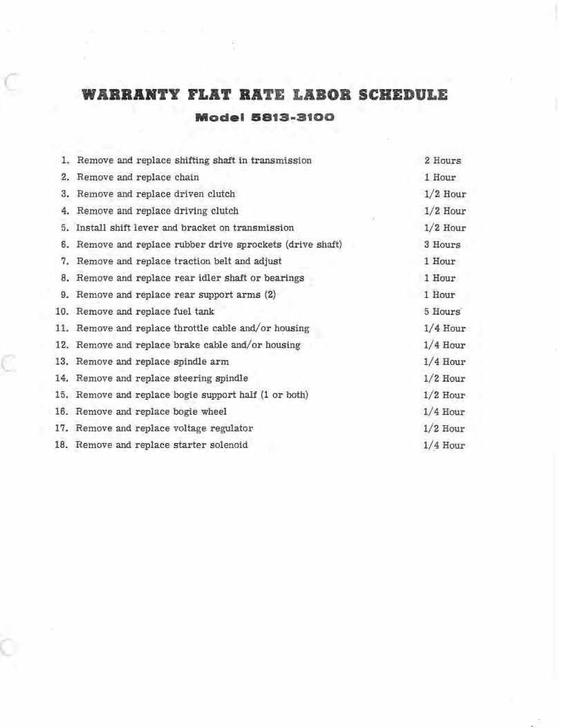
c WARRANTY FLAT RATE LABOR SCHEDULE Model 5813-3100
I. Remove and replace shifting shaft in transmission 2 Hours
2. Remove and replace chain 1 Hour
3. Remove and replace driven clutch 1/2 Hour
4. Remove and replace driving clutch 1/2 Hour
5. Install shift lever and bracket on transmission 1/2 Hour
6. Remove and replace rubber drive sprockets (drive shaft) 3 Hours
7. Remove and replace traction belt and adjust 1 Hour
8. Remove and replace rear idler shaft or bearings 1 Hour
9. Remove and replace rear support arms (2) 1 Hour
10. Remove and replace fuel tank 5 Hours·
1I. Remove and replace throttle cable and/or housing 1/4 Hour
12. Remove and replace brake cable and/or housing 1/4 Hour
C 13. Remove and replace spindle arm 1/4 Hour
14. Remove and replace steering spindle 1/2 Hour
15. Remove and replace bogie support half (lor both) 1/2 Hour
16. Remove and replace bogie wheel 1/4 Hour
17. Remove and replace voltage regulator 1/2 Hour
18. Remove and replace starter solenoid 1/4 Hour
c
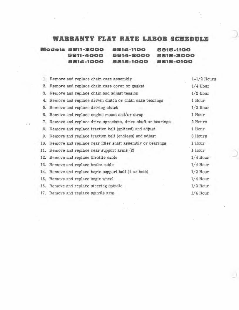
WARRANTY FLAT RATE LABOR SCHEDULE
Models 5811-3000 5811-4000 5814-1000
5814-1100 5814-2000 5815-1000
5815-1100 5815-2000 5818-0100
1. Remove and replace chain case assembly 1-1/2 Hours
2. Remove and replace chain case cover or gasket 1/4 Hour
3. Remove and replace chain and adjust tension 1/2 Hour
4. Remove and replace driven clutch or chain case bearings 1 Hour
5. Remove and replace driving clutch 1/2 Hour
6. Remove and replace engine mount and/or strap 1 Hour --
7. Remove and replace drive sprockets, drive shaft or bearings 2 Hours
8. Remove and replace traction belt (spliced) and adjust 1 Hour
9. Remoye and replace traction belt (endless) and adjust 3 Hours
10. Remove and replace rear idler shaft assembly or bearings 1 Hour
11. Remove and replace rear support arms (2) 1 Hour
12. Remove and replace throttle cable 1/4 Hour
13. Remove and replace brake cable 1/4 Hour
14. Remove and replace bogie support half (lor both) 1/2 Hour
15. Remove and replace bogie wheel 1/4 Hour
16. Remove and replace steering spindle 1/2 Hour
17. Remove and replace spindle arm 1/4 Hour
)
)
)
c
c
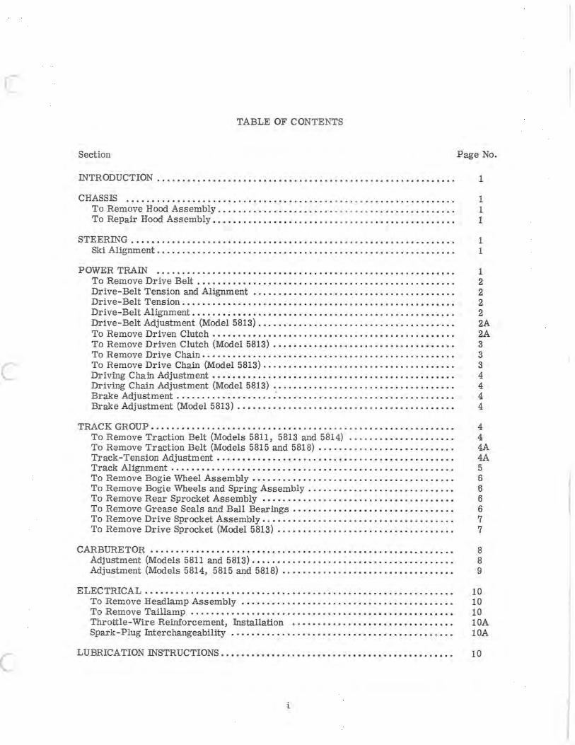
TABLE OF CONTENTS
Section Page No.
INTRODUCTION .. . . . . . . . . . . . . . . . . • . . . . . . . . . . . . . . . . . . . . . . . . . . . . . . . . . . . . • . . . 1
CHASSIS ......................................... . .. ... ... ............... 1 To Remove Hood Assembly ....................... ........ .. ........... " . 1 To Repair Hood Assembly. • . . . . . . . . . . . . . . . . . . . . . . . . . . . . . . . . . . . . . . . . . . . . . . 1
STEERING.......................................... . .... ........... ...... 1 Ski Alignment. . . . . . . . . . . . . . . . . . . . . . . . . . . . . . . . . . . . . . . . . . . . . . . . . . . . . . . . . . . 1
POWER TRAIN .......................................................... . To Remove Drive Belt .................................................. . Drive-Belt Tension and Alignment .............•.•........................ Drive-Belt Tension ..................................................... . Drive-Belt Alignment ...............................•.................... Drive-Belt Adjustment (Model 5813) ...•............ ......... .............. To Remove Driven Clutch ........•......................•..........•..... To Remove Driven Clutch (Model 5813) ................................... . To Remove Drive Chain ...... . ........................ ....... .... . ...... . To Remove Drive Chain (Model 5813) ......... ..... . ...................... . Driving Chain Adjustment ...............................•................ Driving Chain Adjustment (Model 5813) .......•.......... . ....... .. .. ...... Brake Adjustment .................................. ..... . . .............. . Brake Adjustment (Model 5813) .................. ...•........ .............
1 2 2 2 2 2A 2A 3 3 3 4 4 4 4
TRACK GROUP. . . . . . . . . . . . . . . . . . . . . . . . . . . . . . . . . . . . . . . . . . . . . . . . . . • . . . . . . . . . 4 To Remove Traction Belt (Models 5811, 5813 and 5814) . . . . ... ......... .. ... 4 To Remove Traction Belt (Models 5815 and 5818) . .. . . . . . .. . .. .. . . . . . . . . . .. . 4A Track-Tension Adjustment.......... ... .... .. . ... . ................. .. .... 4A Track Alignment . . . . . . . . . . . . . . . . . . . . . . . . . . . . . . . . . . . . . . . . . . . . . . . . . . . . . . . . 5 To Remove Bogie Wheel Assembly. . . . . . . . . . . . . . . . . . . . . • . . . . . . . . . . . . . . . . . . 6 To Remove Bogie Wheels and Spring Assembly . . . . . . . . . . . . . . . . . . . . . . . . . . . . . 6 To Remove Rear Sprocket Assembly .......... .. . . ........•............... 6 To Remove Grease Seals and Ball Bearings . . . . . . . . . . . . . . . . . . . . . . . . . . . . . . . . 6 To Remove Drive Sprocket Assembly. . . . . . . . . . . . . . . . . . . . . . . . • . . . . . . • . . . . . . 7 To Remove Drive Sprocket (Model 5813) . . . . . . . . . .. .. .. .. .. .• .. ... .. . . . . . . . 7
CARBURETOR............................................................ 8 Adjustment (Models 5811 and 5813) . . . . . . . . . . . . . . . . . . . . . . . . . . . . . . . . . . . . . . . • 8 Adjustment (Models 5814, 5815 and 5818) .. ........•..........•.........•.. 9
ELECTRICAL............................................................. 10 To Remove Headlamp Assembly. . . . . .. .. .•. . .•. . . .. .. ..•.•. . .. .. .•.. .•. •. 10 To Remove Taillamp ......•..................•....•......•...•.•..•..... 10 Throttle-Wire Reinforcement, Installation .....................•.......... lOA Spark-Plug Interchangeability . .. ..•......... ....... ....• .. .......•... 0. • • lOA
LUBRICATION INSTRUCTIONS................. .......•...........•......... 10
i
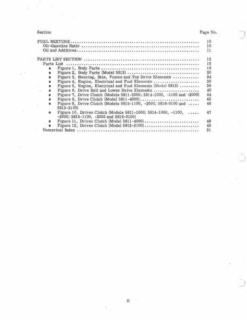
Section Page No.
FUE L MIXTURE. . . . . • . . . . . . . . . . . . . . . . . . . . . . . . . . . . . . . . . . . . . . • . . . . . . . . . . . . . . 10 Oil -Gasoline Ratio •..................................................... 10 Oil and Additives. . • . . . . . • . . . . . . . . . . . . . . . . . . . . . . . . . • . . . . . . . . . . . . . . . . . . . . . 11
PARTS LIST SECTION...... ......... .... ..... .. ... .... ..•........ . ... ..•.. 15 Parts List ...................................... ...... .....•........... 15
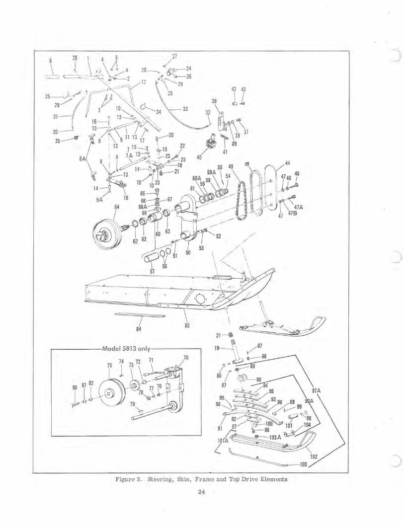
• Figure 1, Body Parts . . . . . . . . . . . . . . . . . . . . • . . . . . . . . . . . . . . . . . . . . . . . • 16 • Figure 2, Body Parts (Model 5813) •. . . ..• .•.• •• ••• •• . •. •• •• . • . . . ... 20 • Figure 3, Steering, Skis, Frame and Top Drive Elements.... ........ 24 • Figure 4, Engine, Electrical and Fuel Elements. . . . . . • . . . . . . . . • . . . . . 30 • Figure 5, Engine, Electrical and Fuel Elements (Model 5813) . .. . ...• . 36 • Figure 6, Drive Belt and Lower Drive Elements . . .. . . .. . .. .. . . . .. .. . 40 • Figure 7, Drive Clutch (Models 5811 - 3000; 5814-1000, -1100 and -2000) 44 • Figure 8, Drive Clutch (Model 5811-4000) • . . . . . . . . . . . . . . . . . . . . . . . . • . 45 • Figure 9, Drive Clutch (Models 5815-1100, -2000; 5818-0100 and 46
5813-3100) • Figure 10, Driven Clutch (Models 5811-1000; 5814-1000, -1100, 47
-2000; 5815-1100, -2000 and 5818-0100) • Figure 11, Driven Clutch (Model 5811-4000) . . • . . . • . . . . . . . . . • • . . . • . . . 48 • Figure 12, Driven Clutch (Model 5813-3100). ..•. • ...•..•..•. ..•.•..• 49
Numerical Index. . .. . . . . . . . . . .. . .. .. .. .. . . . . . . . .. . .. ... .. ... ... . . . .. .. .. 51
ii
c
c
INTRODUCTION This maintenance manual contains service instructions for the following AMF Ski-Daddler snowmobiles:
Sno-Scout - Models 5811-3000 and 5811 -4000 Super Scout II - Models 5814-1100 5814-1100 and 5814-2000 Super Scout 111-Models 5815-1000 and 5815-2000 Wide Track 18 - Model 5818-0100 Wide Track 22 - Model 5813-3100
If the information is not applicable to anyone of the above models, the exceptions wtll be noted and the correct information for the particular model wtll be given.
CHASSIS TO REMOVE HOOD ASSEMBLY
1. Disconnect ignition wiring at the connector plug below the dashboard.
2. Release the left- and right-hand holddown straps securing the hood ass embly to the main frame.
3. Release the front hood release knob and carefully lift the hood assembly clear.
4. Reassembly is the reverse of removal.
TO REPAIR HOOD ASSEMBLY
Repair material for the fiber glass hoods and the Model 5818 Cycolac-L plastic hood can be purchased locally through any auto-parts or marine supply stores. Follow vendor' s ins tructions carefully when making repairs.
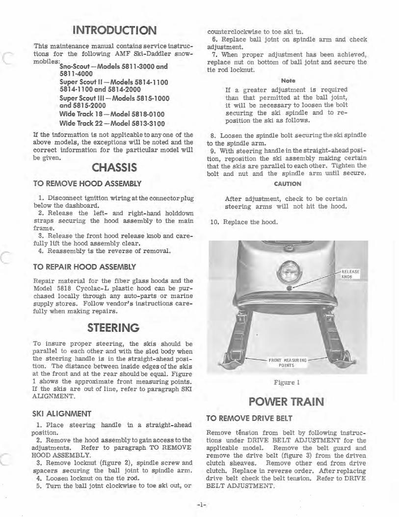
STEERING To insure proper steering, the skis should be parallel to each other and with the sled body when the steering handle is in the straight- ahead position. The distance between inside edges of the skis at the front and at the rear should be equal. Figure 1 shows the approximate front measuring points. If the skis are out of line, refer to paragraph SKI ALIGNMENT.
SKI ALIGNMENT
1. Place steering handle in a straight- ahead position.
2. Remove the hood assembly to gain access to the adjustments. Refer to paragraph. TO REMOVE HOOD ASSEMBLY.
3. Remove locknut (figure 2), spindle screw and spacers securing the ball joint to spindle arm . 4. Loosen locknut on the tie rod. 5. Turn the ball joint clockwise to toe ski out, or
- 1-
counterclockwise to toe ski tn. 6. Replace ball joint on spindle arm and check
adjustment. 7. When proper adjustment has been achieved,
replace nut on bottom of ball joint and secure the tie rod locknut.
Note
If a greater adjustment is required than that permitted at the ball joint, it will be necessary to loosen the bolt securing the ski spindle and to reposition the ski as follows.
8. Loosen the spindle bolt securing the ski spindle to the spindle arm.
9. With steering handle in the straight-aheadposition, reposition the ski assembly making certain that the skis are parallel to each other. Tighten the bolt and nut and the spindle arm until secure.
CAUTION
After adjustment, check to be certain steering arms wtll not hit the hood.
10. Replace the hood.
• . - --- FRONT MEA SUR ING POINTS
Figure 1
POWER TRAIN
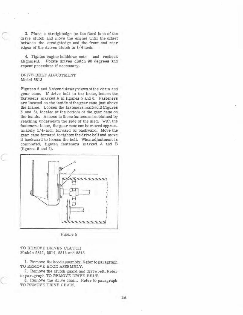
TO REMOVE DRIVE BELT
Remove tension from belt by following instructions under DRIVE BE L T ADJUSTMENT for the applicable model. Remove the belt guard and remove the drive belt (figure 3) from the driven clutch sheaves. Remove other end from drive clutch. Replace in reverse order. After replacing drive belt check the belt tension. Refer to DRIVE BELT ADJUSTMENT.
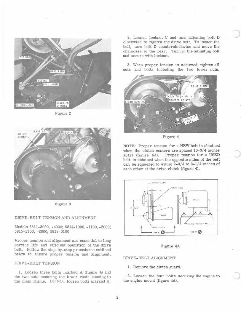
Figure 2
Figure 3
DRIVE-BELT TENSION AND ALIGNMENT
Models 5811-3000, -4000; 5814-1000, -1100, -2000; 5815-1100, -2000; 5818-0100
Proper tension and alignment are essential to long service life and efficient operation of the drive belt. Follow the step-by-step procedures outlined below to ensure proper tension and alignment.
DRIVE-BELT TENSION
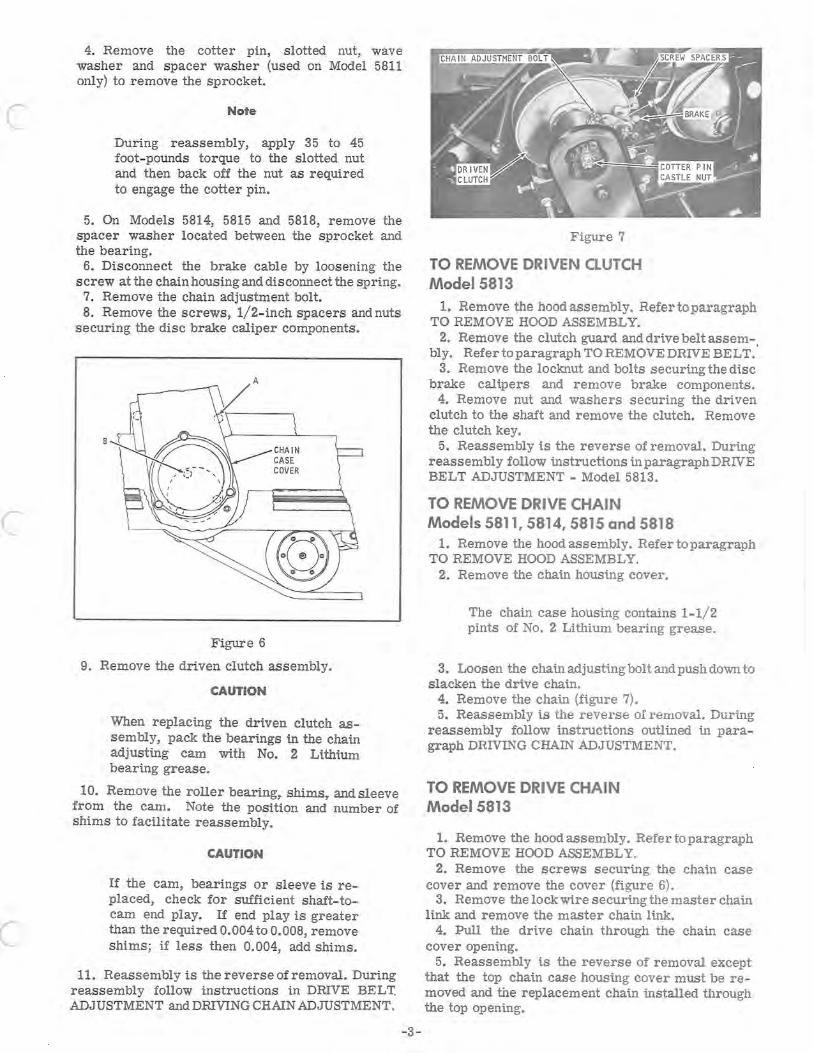
1. Loosen three bolts marked A (figure 4) and the two nuts securing the lower chain housing to the main frame. DO NOT loosen bolts marked B.
2
2. Loosen locknut C and turn adjusting bolt D clockwise to tighten the drive belt. To loosen the belt, turn bolt D counterclockwise and move the chaincase to the rear. Turn in the adjusting bolt and secure with locknut.
3. When proper tension is achieved, tighten all nuts and bolts including the two lower nuts.
Figure 4
NOTE: Proper tension for a NEW belt is obtained when the clutch centers are spaced 10-3/4 inches apart (figure 4A). Proper tension for a USED belt is obtained when the opposite sides of the belt can be squeezed to within 2-3/ 4 to 3-1/4 inches of each other at the drive clutch (figure 4).
OR I VEN CLU TCH
'; TRAl r.HI EOG£
;:: NG lt-I [ HOLD DOWN NUT S
• 'oR IV[ CLUTCH ~ L- VIEW" V1EWO
Figure 4A .
DRIVE-BELT ALIGNMENT
1. Remove the clutch guard.
2. Loosen the four bolts securing the engine to the engine mount (figure 4A).
)
c
c
c
3. Place a straightedge on the fixed face of the drive clutch and move the engine until the offset between the straightedge and the front and rear edges of the driven clutch is 1/4 inch.
4. Tighten engine holddown nuts and recheck alignment. Rotate driven clutch 90 degrees and repeat procedure if necessary.
DRIVE BELT ADJUSTMENT Model 5813
Figures 5 and 6 show cutaway views of the chain and gear case. If drive belt is too loose, loosen the fasteners marked A in figures 5 and 6. Fasteners are located on the inside of the gear case just above the frame. Loosen the fasteners marked B (figures 5 and 6), located at the bottom of the gear case on the inside. Access to these fasteners is obtained by reaching underneath the side of the sled. With the fasteners loose, the gear case can be moved approximately 1/4-inch forward or backward. Move the gear case forward to tighten the drive belt and move it backward to loosen the belt. When adjustment is completed, tighten fasteners marked A and B (figures 5 and 6).
A
Figure 5
TO REMOVE DRIVEN CLUTCH Models 5811, 5814, 5815 and 5818
1. Remove the hood assembly. Refer to paragraph TO REMOVE HOOD ASSEMBLY.
2. Remove the clutch guard and drive belt. Refer to paragraph TO REMOVE DRIVE BELT.
3. Remove the drive chain. Refer to paragraph TO REMOVE DRIVE CHAIN.
2A

c
c
4. Remove the cotter pin, slotted nut, wave washer and spacer washer (used on Model 5811 only) to remove the sprocket.
Note
During reassembly, apply 35 to 45 foot-pounds torque to the slotted nut and then back off the nut as required to engage the cotter pin.
5. On Models 5814, 5815 and 5818, remove the spacer washer located between the sprocket and the bearing.
6. Disconnect the brake cable by loosening the screw at the chain housing and disconnect the spring.
7. Remove the chain adjustment bolt. 8. Remove the screws, 1/2-inch spacers and nuts
securing the disc brake caliper components.
A
Figure 6
9. Remove the driven clutch assembly.
CAUTION
When replacing the driven clutch assembly, pack the bearings in the chain adjusting Cam with No. 2 Lithium bearing grease.
10. Remove the roller bearing,. shims,. andsleeve from the cam. Note the position and number of shims to facilitate reassembly.
CAUTION
If the cam, bearings or sleeve is replaced, check for sufficient shaft-tocam end play. If end play is greater than the required 0.004 to 0.008, remove shims; if less then 0.004, add shims.
11. Reassembly is the reverse of removal. During reassembly follow instructions in DRIVE BELT ADJUSTMENT and DRIVING CHAIN ADJUSTMENT.
-3-
Figure 7
TO REMOVE DRIVEN CLUTCH Model 5813
1. Remove the hood assembly. Refertoparagraph TO REMOVE HOOD ASSEMBLY.
2. Remove the clutch guard and drive belt assem-. bly. Refer to paragraph TO REMOVE DRIVE BELT.
3. Remove the locknut and bolts securing the disc brake calipers and remove brake components.
4. Remove nut and washers securing the driven clutch to the shaft and remove the clutch. Remove the clutch key.
5. Reassembly is the reverse of removal. During reassembly follow instructions in paragraph DRIVE BELT ADJUSTMENT - Model 5813.
TO REMOVE DRIVE CHAIN Models 5811,5814,5815 and 5818
1. Remove the hood assembly. Refer to paragraph TO REMOVE HOOD ASSEMBLY.
2. Remove the chain housing cover.
The chain Case housing contains 1-1/2 pints of No. 2 Lithium bearing grease.
3. Loosen the chain adjusting bolt and push down to slacken the drive chain.
4. Remove the chain (figure 7). 5. Reassembly is the reverse of removal. During
reassembly follow instructions outlined in paragraph DRIVING CHAIN ADJUSTMENT.
TO REMOVE DRIVE CHAIN Model 5813
1. Remove the hood assembly. Refer to paragraph TO REMOVE HOOD ASSEMBLY.
2. Remove the screws securing the chain case cover and remove the cover (figure 6). . 3. Remove the lock wire securing the master chain link and remove the master chain link.
4. Pull the drive chain through the chain case cover opening.
5. Reassembly is the reverse of removal except that the top chain Case housing cover must be removed and the replacement chain installed through the top opening.
DRIVING CHAIN ADJUSTMENT Models 5811, 5814, 5815 and 5818
1. Remove the hood assembly. Lay Ski- Daddler on right-hand side and remove the chain housing cover (figure 4).
The chain case housing contains 1-1/2 pints of No.2 Lithium bearing grease.
2. Check chain for maximum 1/4-inch slack. 3. If slack is greater than 1/4 inch, loosen the
locknut and chain adjustment bolt. Push bolt up to tighten chain or down to loosen chain.
CAUTION
Be certain brake assembly clears the clutch flange after adjusting chain. If necessary, loosen the two bolts B (figure 4) and reposition brake assembly.
4. When properly adjusted, retighten locknut on adjustment bolt securely and replace cover plate.
DRIVING CHAIN ADJUSTMENT Model 5813
1. Remove the hood assembly. 2. Remove the three screws securing the bottom
cover and remove cover.
The chain case housing contains 1-1/2 pints of No. 2 Lithium bearing grease.
3. Check chain for tension. A properly adjusted chain should have a maximum 1/4- inch slack.
4. Loosen the three screws and clips securing the chain adjustment.
5. Rotate the chain adjustment device counterclockwise as required to tighten the chain.
CAUTION
Rotate the chain adjustment device counterclockwise only. Tightening in the clockwise direction may result in damage to the component.
6. Reassembly is the reverse of removal.
BRAKE ADJUSTMENT Models 5811,5814,5815 and 5818
1. If brake adjustment is needed, remove cotter pin from castle nut on the brake arm and tighten or loosen castle nut until the brake pads just clear the clutch sheave (figure 4). Reinstall cotter pin.
-4-
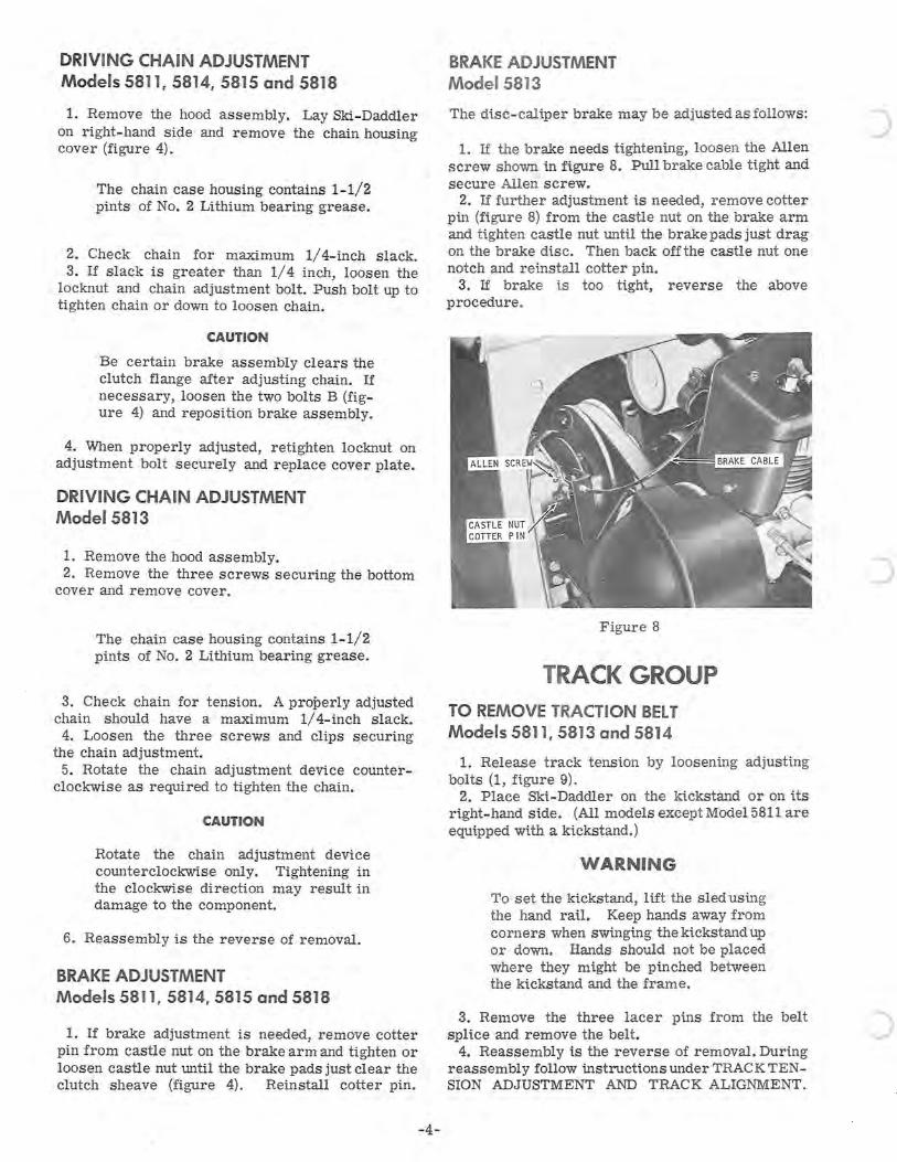
BRAKE ADJUSTMENT Model 5813
The disc-caliper brake may be adjusted as follows:
1. If the brake needs tightening, loosen the Allen screw shown in figure 8. Pull brake cable tight and secure Allen screw.
2. If further adjustment is needed, remove cotter pin (figure 8) from the castle nut on the brake arm and tighten castle nut until the brake pads just drag on the brake disc. Then back off the castle nut one notch and reinstall cotter pin.
3. If brake i.s too ti.ght, reverse the above procedure.
Figure 8
TRACK GROUP
TO REMOVE TRACTION BELT Models 5811, 5813 and 5814
1. Release track tensi.on by looseni.ng adjusting bolts (1, figure 9).
2. Place Ski-Daddler on the ki.ckstand or on i.ts ri.ght-hand si.de. (All models except Model 5811 are equipped with a kickstand.)
WARNING
To set the ki.ckstand, lift the sled usi.ng the hand rail. Keep hands away from corners when swinging the kickstand up or down. Hands should not be placed where they mi.ght be pinched between the kickstand and the frame.
3. Remove the three lacer pins from the belt splice and remove the belt.
4. Reassembly is the reverse of removal. During reassembly follow instructions under TRACK TENSION ADJUSTMENT AND TRACK ALIGNMENT.
c
c
TO REMOVE TRACTION BELT Models 5815 and 5818
1. Place the Ski-Daddler on the kickstand.
WARNING: To set the kickstand, lift the sled using the hand rail. Keep hands away from corners when swinging the kickstand up or down. Hands should not be placed where they might be pinched between the kickstand and the frame.
2. Remove the bogie-wheel assemblies. Refer to paragraph TO REMOVE BOGIE WHEELS AND SPRINGS, steps 1 through 3.
3. Remove the rear-sprocket assembly. Referto paragraph TO REMOVE REAR SPROCKET ASSEMBL Y, steps 1 through 5.
4. Place sled on its right-hand side.
5. Remove drive-sprocket assembly. Refer to paragraph TO REMOVE DRIVE SPROCKET ASSEMBLY.
NOTE: With the removal of the drive-sprocket assembly, the one-piece traction belt will be clear for removal. To replace the traction belt, the procedure is the reverse of removal. During reassembly, follow instructions given in paragraphs TRACK ALIGNMENT, TRACK TENSION ADJUSTMENT, AND DRIVING CHAIN ADJUSTMENT.
TRACK TENSION ADJUSTMENT
Traction-belt life and efficiency depend largely on proper tension and alignment. To adjust tenSion, proceed as follows:
1. Set Ski-Daddler on a clean, flat surfaCe. Do not use the kickstand.
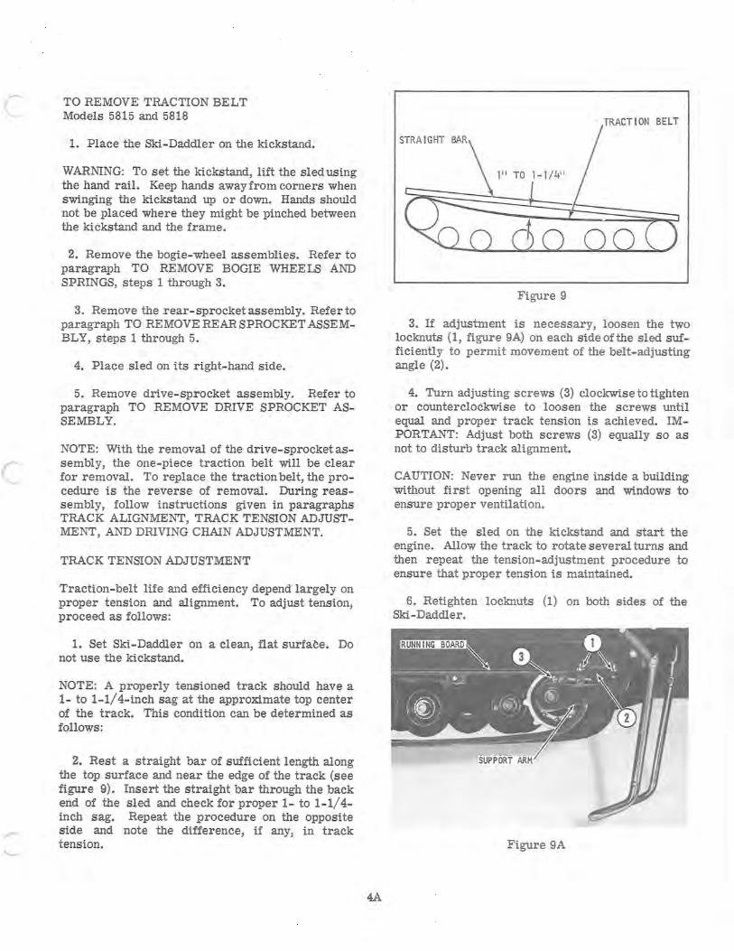
NOTE: A properly tensioned track should have a 1- to 1-1/4-inch sag at the approximate top center of the track. This condition can be determined as follows :
2. Rest a straight bar of sufficient length along the top surface and near the edge of the track (see figure 9). Insert the straight bar through the back end of the sled and check for proper 1- to 1-1/4-inch sag. Repeat the procedure on the opposite side and note the difference, if any, in track tension.
4A
TRACTION BELT
Figure 9
3. If adjustment is necessary, loosen the two locknuts (1, figure 9A) on each side ofthe sled sufficiently to permit movement of the belt-adjusting angle (2).
4. Turn adjusting screws (3) clockwise to tighten or counterclockwise to loosen the screws until equal and proper t rack tension is achieved. IMPORTANT: Adjust both screws (3) equally so as not to disturb track alignment.
CAUTION: Never run the engine inside a building without first opening all doors and windows to ensure proper ventilation.
5. Set the sled on the kickstand and start the engine. Allow the track to rotate several turns and then repeat the tension-adjustment procedure to ensure that proper tension is maintained.
6. Retighten locknuts (I) on both sides of the Ski-Daddler.
Figure 9A

c
TRACK ALIGNMENT
1. Place the sled on the kickstand and run the engine until the clutch engages and the track turns SLOWLY.
2. While the track is turning SLOWLY, stand to the rear of the sled and visually check that the sprocket teeth are centered in the track slots and that the clearance between the track and support arms is the same on each side.
3. If the track is not centered, loosen the two locknuts (1, figure 9A) securing the belt-adjusting angle (2) on each side of the sled. Tighten adjusting screw (3) on the side where the track is closer to the support arm until the track is centered.
4. After track alignment is completed, check track tension. If satisfactory, tighten locknuts (1).
5
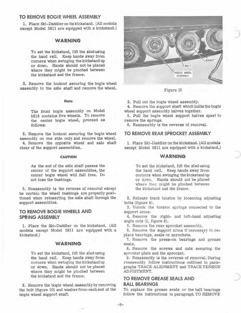
TO REMOVE BOGIE WHEEL ASSEMBLY 1. Place Ski-Daddler on its kickstand. (All models
except Model 5811 are equipped with a kickstand.)
WARNING
To set the kickstand, lift the sled using the hand rail. Keep hands away from corners when swinging the kickstand up or down. Hands should not be placed where they might be pi.nched between the kickstand and the frame.
2. Remove the locknut securing the bogie wheel assembly to the axle shaft and remove the wheel.
Note
The front bogie assembly on Model 5818 contains five wheels. To remOve the center bogie wheel, proceed as follows:
3. Remove the locknut securing the bogie wheel assembly on one side only and remove the wheel.
4. Remove the opposite wheel and axle shaft clear of the support assemblies.
CAUTION
As the end of the axle shaft passes the center of the support assemblies, the center bogie wheel will fall free. Do not lose the bushings.
5. Reassembly is the reverse of removal except be certain the wheel bushings are properly positioned when reinserting the axle shaft through the support assemblies.
TO REMOVE BOGIE WHEELS AND SPRING ASSEMBLY
1. Place the Ski-Daddler on the kickstand. (All models except Model 5811 are equipped with a kickstand.)
WARNING
To set the kickstand, lift the sled using the hand rai.l. Keep hands away from corners when swinging the kickstand up or down. Hands should not be placed where they might be pi.nched between the kickstand and the frame.
2. Remove the bogie wheel assembly by removing the bolt (figure 10) and washer from each end of the bogi.e wheel support shaft.
BOGIE WHEEL ASSEMBLY
Figure 10
3. Pull out the bogie wheel assembly. 4. Remove the support shaft which holds the bogie
wheel support assembly halves together. 5. Pull the bogie wheel support halves apart to
remove the springs. 6. Reassembly is the reverse of removal.
TO REMOVE REAR SPROCKET ASSEMBLY
1. Place Ski.-Daddler on the ki.ckstand. (All models except Model 5811 are equipped with a kickstand.)
WARNING
To set the ki.ckstand, 1 i.ft the sled using the hand rail. Keep hands away from corners when swinging the kickstand up or down. Hands should not be placed where they might be pinched between the kickstand and the frame.
2. Release track tension by loosening adjusting bolts (figure 9).
3. Unlock the torsion springs connected to the support arms.
4. Remove the right- and left-hand adjusting angle nuts (1, figure 9).
5. Remove the rear sprocket assembly. 6. Remove the support arms if necessary to re-
place bearings, seals or sprockets. . 7. Remove the press-on bearings and grease
seals. 8. Remove the screws and nuts securi.ng the
sprocket plate and the sprocket. 9. Reassembly i.s the reverse of removal. During
reassembly follow instructions outlined in paragraphs TRACK ALIGNMENT and TRACK TENSION ADJUSTMENT.
TO REMOVE GREASE SEALS AND BALL BEARINGS To replace the grease seals or the ball bearings follow the i.nstructions in paragraph TO REMOVE
-6-
)
c
c
c
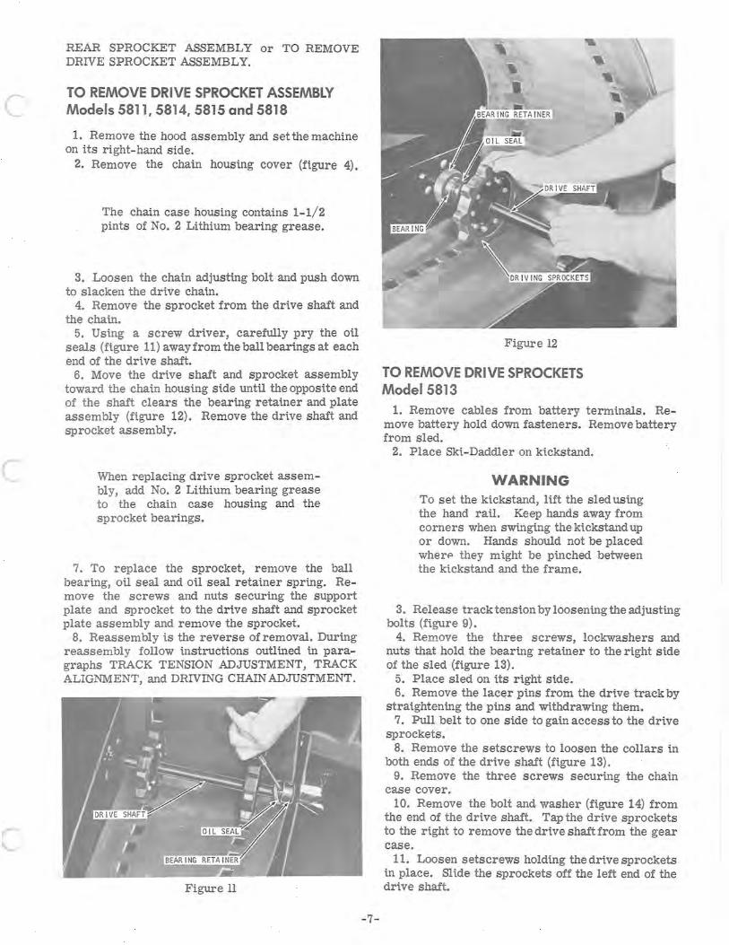
REAR SPROCKET ASSEMBLY or TO REMOVE DRIVE SPROCKET ASSEMBLY.
TO REMOVE DRIVE SPROCKET ASSEMBLY Models 5811,5814,5815 and 5818
1. Remove the hood assembly and set the machine on its right-hand side.
2. Remove the chain housing cover (figure 4).
The chain case housing contains 1-1/2 pints of No.2 Lithium bearing grease.
3. Loosen the chain adjusting bolt and push down to slacken the dri.ve chain.
4. Remove the sprocket from the dri.ve shaft and the chain.
5. Using a screw driver, carefully pry the oil seals (figure 11) away from the ball bearings at each end of the dri.ve shaft.
6. Move the drive shaft and sprocket assembly toward the chain housing side until the opposite end of the shaft clears the beari.ng retai.ner and plate assembly (figure 12). Remove the dri.ve shaft and sprocket assembly.
When replacing drive sprocket as s embly, add No.2 Lithium bearing grease to the chain case housing and the sprocket bearings.
7. To replace the sprocket, remove the ball bearing, oil seal and oU seal r etai.ner spri.ng. RemOve the screws and nuts securi.ng the support plate and sprocket to the drive shaft and sprocket plate assembly and remove the sprocket.
8. Reassembly i.s the reverse of removal. Duri.ng reassembly follow i.nstructions outli.ned i.n paragraphs TRACK TENSION ADJUSTMENT, TRACK ALIGNMENT, and DRIVING CHAIN ADJUSTMENT.
Figure II
-7-
Figure 12
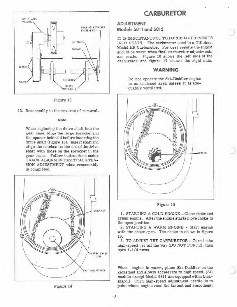
TO REMOVE DRIVE SPROCKETS Model 5813
1. Remove cables from battery termi.nals. Remove battery hold down fasteners. Remove battery from sled.
2. Place Ski.-Daddler on ki.ckstand.
WARNING To set the ki.ckstand, li.ft the sled using the hand rail. Keep hands away from corners when swi.ngi.ng the ki.ckstand up or down. Hands should not be placed wherp they mi.ght be pi.nched between the ki.ckstand and the frame.
3. Release track tensi.on by loosening the adjusting bolts (figure 9).
4. Remove the three screws, lockwashers and nuts that hold the beari.ng retainer to the ri.ght si.de of the sled (figure 13).
5. Place sled on i.ts right si.de. 6. Remove the lacer pi.ns from the dri.ve track by
strai.ghtening the pi.ns and wi.thdrawi.ng them. 7. Pull belt to one si.de to gai.n access to the dri.ve
sprockets. 8. Remove the setscrews to loosen the collars i.n
both ends of the dri.ve shaft (figure 13). 9. Remove the three screws securi.ng the chain
case cover. 10. Remove the bolt and washer (figure 14) from
the end of the dri.ve shaft. Tap the dri.ve sprockets to the ri.ght to remove the dri.ve shaft from the gear case.
11. Loosen setscrews holdi.ng the dri.ve sprockets i.n place. Sli.de the sprockets off the left end of the dri.ve shaft.
CHA IN CASE
HOUSING~
Figure 13
BEARING RETAINER FASTENERS
SETSCREW
12. Reassembly is the reverse of removal.
Note
When replacing the drive shaft into the gear case, align the large sprocket and the spacer behind it before inserting the drive shaft (figure 15). Insertshaftand al ign the notches on the end ofthe drive shaft with those on the sprocket in the gear case. Follow instructions under TRACK ALIGNMENT and TRACK TENSION ADJUSTMENT when reassembly is completed.
BOLT AND WASHER
Figure 14
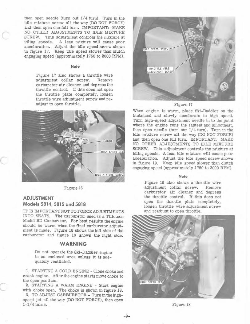
CARBURETOR ADJUSTMENT Models 5811 and 5813
IT IS IMPORT ANT NOT TO FORCE ADJUSTMENTS INTO SEATS. The carburetor used is a Tillotson Model HR Carburetor. For best results the engine should be warm when final carburetor adjustments are made. Figure 16 shows the left side of the carburetor and figure 17 shows the right side.
WARNING
Do not operate the Ski-Daddler engine in an enclosed area unless it is adequately ventUated.
~_~~+.!..+--+_SPACER
Figure 15
1. STARTING A COLD ENGINE - Close choke and crank engine. After the engine starts move choke to the open position.
2. STARTING A WARM ENGINE - Start engine with the choke open. The choke is shown in figure 16.
3. TO ADJUST THE CARBURETOR - Turn in the high-speed jet all the way (DO NOT FORCE), then open 1-1/4 turns.
When engine is warm, place Ski-Daddler on the kickstand and slowly accelerate to high speed. (All models except Model 5811 are equipped with a kickstand.) Turn high-speed adjustment needle in to point where engine runs the fastest and smoothest,
-8-
)
)
c
c
then open needle (turn out 1/4 turn). Turn in the idle mixture screw all the way (DO NOT FORCE) and then open. one full turn. IMPORTANT: MAKE NO OTHER ADJUSTMENTS TO IDLE MIXTURE SCREW. This adjustment controls the mixture at idli.ng speeds. A lean mixture wUI cause poor acceleration. Adjust the idle speed screw shown in fi.gure 17. Keep idle speed s:l.ower than clutch engaging speed (approximately 1750 to 2000 RPM).
Note
Figure 17 also shows a throttle wire adjustment collar screw. Remove carburetor air cleaner and depress the throttle control. If this does not open the throttle plate completely, loosen throttle wire adjustment screw and readjust to open throttle.
Figure 16
ADJUSTMENT Models 5814,5815 and 5818 IT IS IMPORTANT NOT TO FORCE ADJUSTMENTS INTO SEATS. The carburetor used is a Ti.llotson Model HD Carburetor. For best results the engine should be warm when the fi.nal carburetor adjustment is made. Figure 18 shows the left side of the carburetor and fi.gure 19 shows the right side.
WARNING
Do not operate the Ski-Daddler engine in an enclosed area unless it is adequately ventilated.
1. STARTING A COLD ENGINE - Close choke and crank engine. Mter the engine starts move choke to the open pOSition.
2. STARTING A WARM ENGINE - Start engine with choke open. The choke is shown in figure 18.
3. TO ADJUST CARBURETOR - Turn in the highspeed jet all the way (DO NOT FORCE), then open 1-1/4 turns.
-9-
Figure 17
When engine is warm, place Ski-Daddler on the kickstand and slowly accelerate to high speed. Turn high-speed adjustment needle in to the point where the engine runs the fastest and smoothest, then open needle (turn out 1/4 turn). Turn in the idle mixture screw all the way (DO NOT FORCE) and then open one full turn. IMPORT ANT: MAKE NO OTHER ADJUSTMENTS TO IDLE MIXTURE SCREW. This adjustment controls the mixture at idli.ng speeds. A lean idle mixture wi.ll cause poor acceleration. Adjust the idle speed screw shown in figure 19. Keep idle speed slower than clutch engaging speed (approximately 1750 to 2000 RPM)
Note
Figure 19 also shows a throttle wire adjustment collar screw. Remove carburetor air cleaner and depress the throttle control. If this does not open the throttle plate completely, loosen throttle wire adjustment screw and readjust to open throttle.
Figure 18
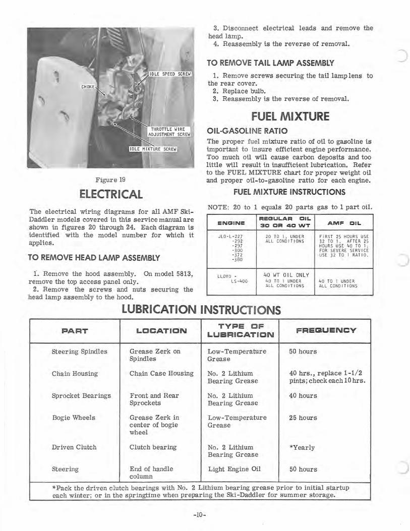
Figure 19
ELECTRICAL The electrical wiring diagrams for all AMF SkiDaddler models covered in this service manual are shown in fi.gures 20 through 24. Each diagram is identifi.ed witb the model number for which i.t applies.
TO REMOVE HEAD LAMP ASSEMBLY
1. Remove the hood assembly. On model 5813, remove the top access panel only.
2. Remove the screws and nuts securing the head lamp assembly to the hood.
3. Disconnect electrical leads and remove the head lamp.
4. Reassembly is the reverse of removal.
TO REMOVE TAIL LAMP ASSEMBLY
1. Remove screws securing the tail lamp lens to the rear cover.
2. Replace bulb. 3. Reassembly is the reverse of removal.
FUEL MIXTURE OIL-GASOLI NE RATIO The proper fuel mixture ratio of oil to gasoline is important to insure effi.cient engine performance. Too much oi.l wi.1l cause carbon deposits and too little wi.ll result in insuffi.cient lubricati.on. Refer to the FUEL MIXTURE chart for proper weight oi.l and proper oi.l-to-gaso1i.ne ratio for each engine.
FUEL MIXTURE INSTRUCTIONS
NOTE: 20 to 1 equals 20 parts gas to 1 part oil.
REGULAR OIL ENGINE 3D DR 4DWT AMF OIL
JLO - L- 227 20 TO I, UNDER FIRST 25 HOUR S US E - 292 ALL CONDITION S 32 TO I, AFTER 25 -2 97 HOURS USE 40 TO I; -300 FOR SEVERE SERV ICE - 372 USE 32 TO I RATIO. -3 80
LL OYD - 40 WT OIL ONLY LS -400 40 TO I UNDER 40 TO I UNDER
AL L CONDITIONS ALL CONDITIONS
LUBRICATION INSTRUCTIONS
PART LOCATION TYPE OF FREGUENCY
LUBRICATION
Steering Spindles Grease Zerk on Low-Temperature 50 hours Spindles Grease
Chain Housing Chain Case Housing No. 2 Lithium 40 hrs., replace 1-1/2 Bearing Grease pints; check each 10 hrs.
Sprocket Bearings Front and Rear No. 2 Lithium 40 hours Sprockets Bearing Grease
Bogie Wheels Grease Zerk in Low-Temperature 25 hours center of bogie Grease wheel
Driven Clutch Clutch bearing No. 2 Lithium *Yearly Bearing Grease
Steering End of handle Light Engine Oil 50 hours column
*Pack the driven clutch bearings with No. 2 Lithium bearing grease prior to initial startup each winter; or in the springtime when preparing the Ski-Daddler for summer storage.
-10-
)
c
c
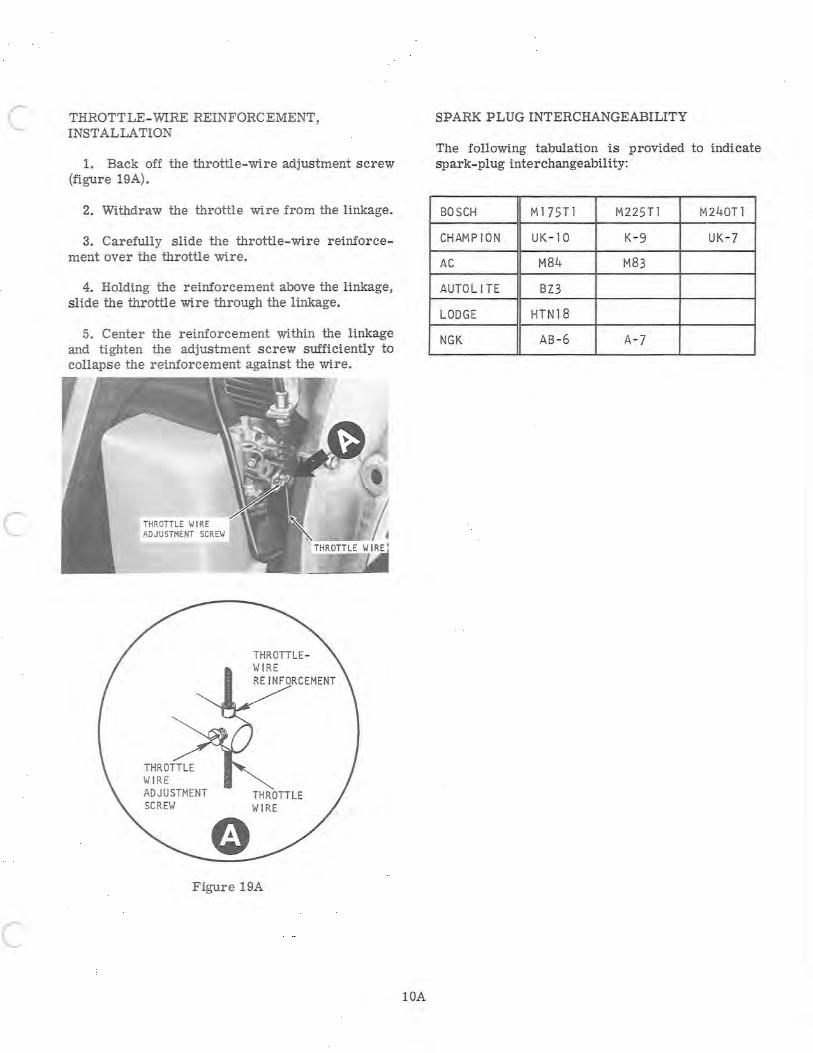
THROTTLE-WIRE REINFORCEMENT, INST ALLA TION
1. Back off the throttle-wire adjustment screw (figure 19A).
2. Withdraw the throttle wire from the linkage.
3. Carefully slide the throttle-wire reinforcement over the throttle wire.
4. Holding the reinforcement above the linkage, slide the throttle wire through the linkage.
5. Center the reinforcement within the linkage and tighten the adjustment screw sufficiently to collapse the reinforcement against the wire.
THROTTLE WIRE ADJUSTMENT SCREW
THROTTLE WIRE REINFORCEMENT
THROTTLE WIRE
Figure 19A
IDA
SPARK PLUG INTERCHANGEABILITY
The following tabulation is provided to indicate spark-plug interchangeability:
BOSCH M175Tl M225Tl M240Tl
CHAMP ION UK - IO K-9 UK -7
AC M84 M83
AUTOLITE BZ3
LODGE HTN18
NGK AB -6 A-7

c
c
WARNING Gasoline and oil should be mixed at temperatures above freezing. Below freezing, gas and oil mix with difficulty. Mix with care or damage to engine could result.
Use only a good grade of SAE 30 or 40 Wt. nondetergent automotive engine or 2-cycle motor oil. Do not us e light duty oils or multiviscosity oils.
Use a good grade of regular, fresh gasoline only. Do not use gasoline left over from summer uses.
Mix the gasoline and oil thoroughly in a clean container kept for this purpose only. Best way to insure a good mix is to add oil to an empty or about half-full container of gasoline and then fill with gasoline and mix thoroughly. Pour the mixed fuel from the container into the gasoline tank. Use a funnel with a fine screen strainer when filling tank. Fill tank slowly to avoid air pockets and spillage.
OIL AND ADDITIVES
Fuels containing additives are not recommended for use in the Ski-Daddler engines. Use only oil that is recommended for use in air- cooled, 2-cycle engines such as an AMF oil or an equivalent nondetergent motor oil (see FUEL MIXTURE chart).
CAUTION
Some outboard motor oils contain a detergent that works well in outboard motors that operate at much lower temperatures because they are water cooled. However, the detergents may cause spark plug fouling in the aircooled engines used on the Ski-Daddler.
Note
A small amount of Dri-Gas or equivalent may be added to the fuel system if moisture from condensation is evident.
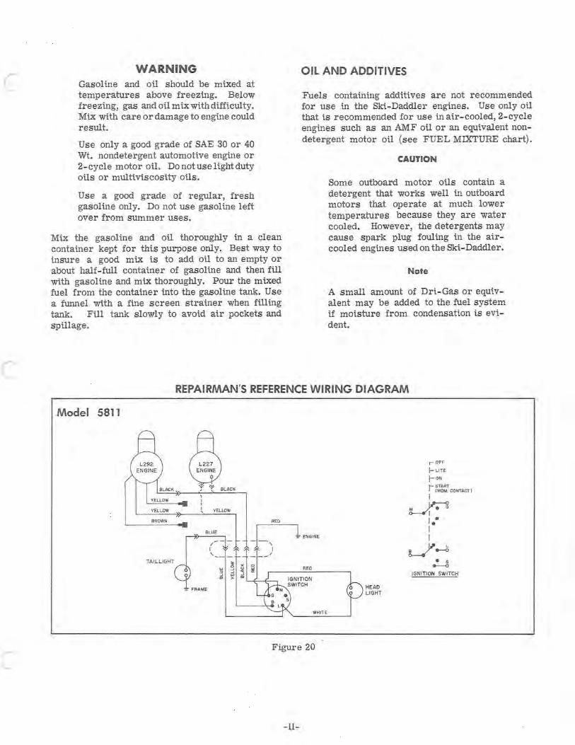
REPAIRMAN'S REFERENCE WIRING DIAGRAM
Model 5811
, , ,
RED
_hlENGINE
I - - _/ TAILLIGHT I, ___ ;.
~ j ~ ~ RED -' w -' '" >- "' L...f~::"""'"
':' FRAMe:
WHITE
Figure 20
-11-
HEAD LIGHT
r OFF
I- LITE
I-ON
1- r~~~: CONTACT)
I
~ I.· I I
J---t • 5 e----o
IGNI TION SWITCH
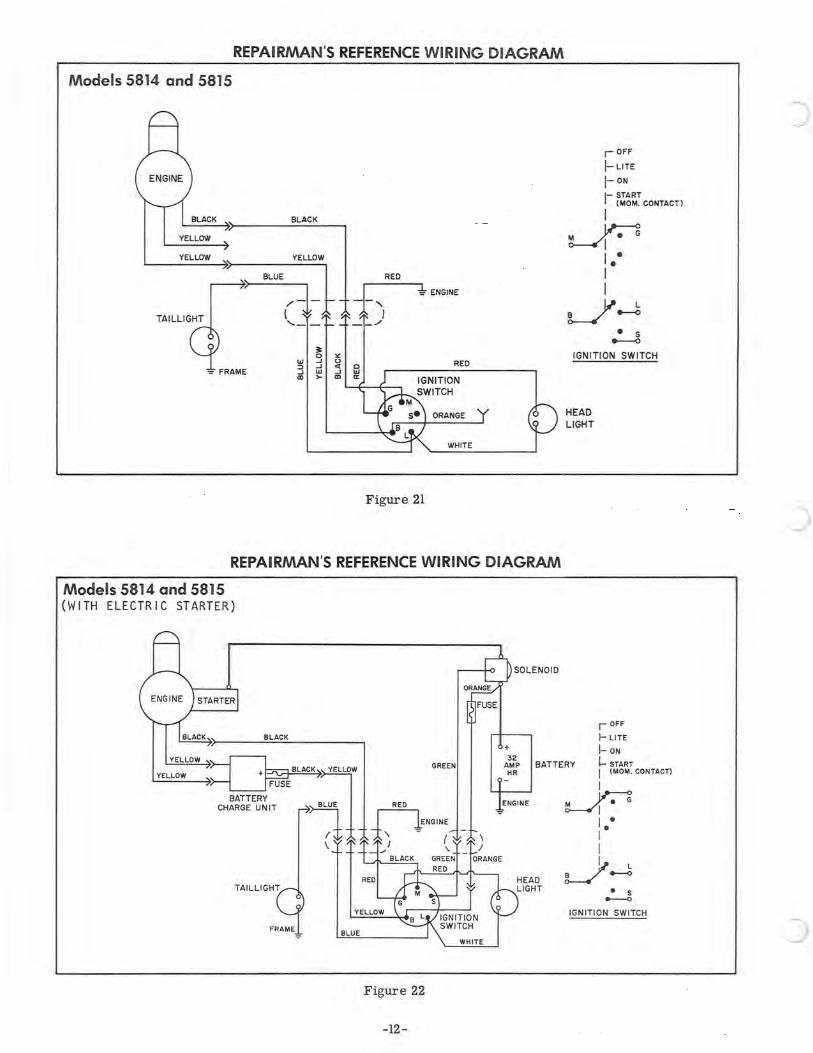
REPAIRMAN'S REFERENCE WIRING DIAGRAM
Models 5814 and 5815
YELLOW
YELLOW
TAILLIGHT
BLACK
~YELLOW
~-l '---
~
w 3 ::J ...J ...J W CD >-
RED
"1 ENGINE
Figure 21
REPAIRMAN'S REFERENCE WIRING DIAGRAM
Models 5814 and 5815 (WITH ELECTRIC STARTER)
BLACK
SOLENOID
r OFF
I-LITE
1- ON
1- ~~~~T CONTACT)
I
~ I. • I I
J~ • 5 --..0
IGNITION SWITCH
HEAD LIGHT
,- OFF
f- LITE
I- ON YELLOW
~_~LACK"~YELLOW ~
GREEN
+ 32
AMP HR
BATTERY ~ START
YELLOW
BATTERY
CHARGE UNIT ~ BL;j
\
BLUE
Figure 22
-12-
I ("10"1. CONTACT)
I
~ I. • I I ~ L
L-/ e--<>
• S ~
IGNITION SWITCH
)
c
c
c
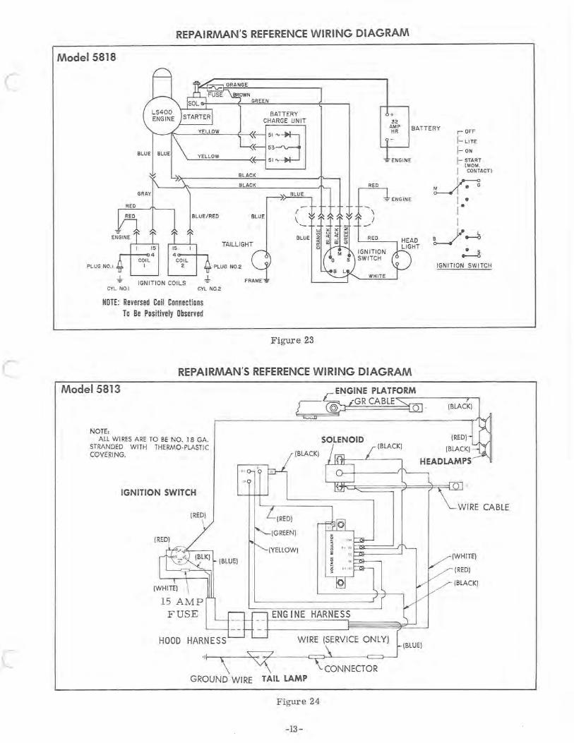
REPAIRMAN'S REFERENCE WIRING DIAGRAM
Model 5818
YELLOW
BATTERY CHARGE UNIT
:~~~ ~~Y~EL~L~OW~ _____ a~ 51~~
15
.--+-----€l 4 COIL
BLUE/RED
15
4 e----!---.
BLACK
BLACK
BLUE
TAILLIGHT
PLUG NO.1 I COIL
2 PLUG NO.2
"J, IGNI T ION COILS
CYL NO.1 CYL NO.2
NOTE: Reversed Coil Connections To Be Positively Observed
Figure 23
+ 32
AMP HR
~ ENGINE
REPAIRMAN'S REFERENCE WIRING DIAGRAM
Model 5813
NOTE, ALL WI RES A RE TO BE NO. 1 8 GA.
STRANDED WITH THERMO-PLASTIC COVERING.
IGNITION SWITCH
(RED)
\
15 AMP FUSE
HOOD
GROUND WIRE
(BLACK)
(RED)
(GREEN)
(YELLOW)
ENGINE HARNESS
WIRE (SERVICE ONLY)
CONNECTOR TAIL LAMP
Figure 24
-13-
BATTERY r OFF
1- LITE
1- ON
1- START (MOM. I CONTACT )
~ I -I-I
J~ - S ..---0
IGNITION SWITCH
WIRE CABLE
(WHITE)
(RED)
(BLACK)

c
c
c
PARTS LIST SECTION
PARTS- LIST SECTION
This portion of the dealer's manual consists of two sections, an illustrated parts list and a numerical index.
PARTS LIST
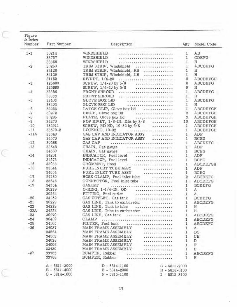
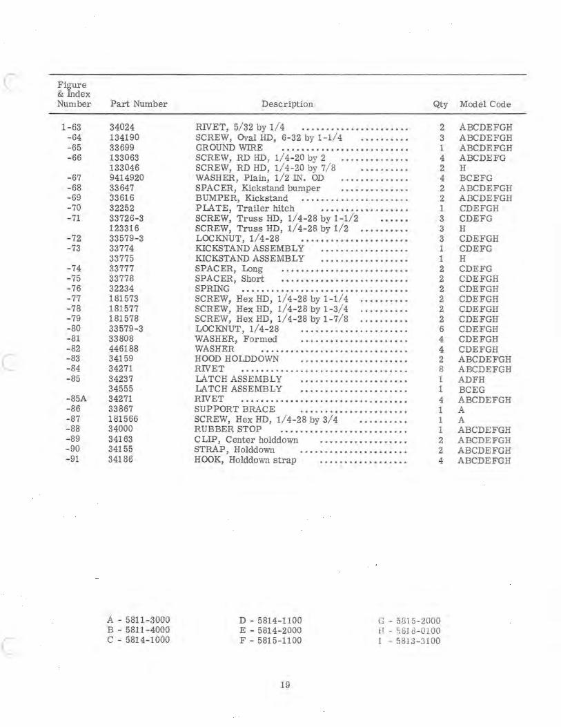
The parts-list portion consists essentially of exploded-view illustrations, keyed to the figurereference column by index numbers. The list is arranged in the following columns:
Figure-and- Index Number. The number preceding the dash refers to the figure number on which the item is shown. The number following the dash refers to the part as indicated on the exploded view.
Part Number. The second column calls out the AMF part number applicable to the figure-andindex number and its corresponding index number on the exploded view.
Description. The description column identifies the part with descriptive nomenclature. In all cases, standard hardware is further des cribed with data covering thread size, length, ID, OD and thickness where necessary.
Quantity. This column provides the total number of item units required for the particular application indicated by the item number.
Model Code. This column codes the Ski- Daddler models for which the part applies. The following lists the code- to-model relationship:
• A - 5811 - 3000 • F - 5815- 1100 • B - 5811-4000 • G - 5815- 2000 • C - 5814-1000 • H - 5818-0100 • D - 5814-1100 • I - 5813-3100 • E - 5814- 2000
15
Where no code letter appears in the model-column, the part applies to all models.
All model codes will be listed at the bottom of each parts listing to provide a ready reference.
NUMERICAL INDEX
The numerical index is provided to afford dealers and distributors with a means of determining to which models their stock applies. The index consists of the following three columns:
Part-Number Column. The part- number column tabulates all parts called out in the parts list. The part numbers are listed in numerical order starting with the first digit in the number. It should be noted, for example, that a four - digit number starting with the number 8 would be listed after a five-digit number starting with a 3 or a six-digit number starting with a 1.
Index-Number Column. The index-number column reflects the figure - and-index number of the part within the parts list.
Quantity Column. The quantity column reflects the total number of parts required for the particular figure-and- index- number application. In certain cases, quantities differ between sled models. This circumstance is covered by providing the same figure-and-index number with different quantities. In referring to the parts-list section, the proper quantity per sled may be determined.

..... en
61 6~ 60 63 64 ~ ~ / / 65 ~ --. ~J~( ---.A ~
52
6667 6869 \ \ \ I \p1l10-
8\\ \ 8174 76
80<!~~ I j",,'~~79 ~ "'t
/ 78
u
~ 14 Ll. ~ ::~~11A
..,"" 15", .
of:, ~ '1 5 6 10 11~ C. /" 9~_ --t ~ .;:). ..
r~ ?:=1 '''~'''''9 7 8 ~~ /; ___ 7 8
51 /
48 46~ ~ 47
/ O~49A ~ 26 49~
J
Figure 1. Body Parts
u
I ~1 36 ~ /85 34 18"'$ (
===~r 7 ~--.J 41 ~O 85A / ~ l~~- / ~
EY' 53 '" ~
[J3,~ . 54 22 22A
/V 55
Q-':j V56
~59 .... _57 ~-58
tf- 21 42 35 '(;7 -'~ 37 ®'\ \
Ii) 38 39 "---37 '
e 31//~~-----27
33 / 1[ . 32
28r ;t, 30 /
u
~ Figure
c
c
& fudex Number
1-1
-2
-3
- 4
-5
-6 -7 -8 -9 - 10 -11 -11A
-12 -13
-14
-15 -16
-17 -18 -19
-20 -21 - 22 - 22A - 23 -24 -25 -26
-27
Part Number
30214 33757 33358 30250 34128 34129 31152 125680 125680 33386 33333 33403 33402 32253 30272 30285 34270 132911 33579-2 33649 34570 30268 33648 34569 34261 34573 33033 33644 34554 24180 33646 34154 30279 30264 34152 30229 34229 34228 30270 30489 34105 34037 34564 34563 34038 34006 33430 33763 33788
A - 5811-3000 B - 5811-4000 C - 5814-1000
WINDSHIELD WINDSHIELD WINDSHIELD
Description
TRIM STRIP, Windshield .....••.•••.•..•.• TRIM STRIP, Windshield, RH ••...•.••..•.• TRIM STRIP, Windshield, LH •.••.•.•.••••• RIVNUT, 1/4-20 ...•.•• • ••••••••.•.•••.•.• SCREW, 1/4-20 by 5/8 ••.•.•..•.•..•...• SCREW, 1/4-20 by 5/8 ••••.•••••••.••••. FRONT SHROUD •..•.••••••..•.••..•• . ...• FRONT SHROUD ••...••.•••.••.•.•...•.... GLOVE BOX LID ••••...•..•.•..•.••..• G LOVE BOX LID .••.••.•..••..•.•...•. LA TCH CLIP, Glove box lid .......•.•••.. HINGE, Glove box lid •..•. • •.....• • .••• PLATE, Glove box lid ..••••.•.•.•.•.... POP RIVET, 1/8-IN. DIA by 3/8 •....••..• SCREW, RD HD, 10-32 by 5/8 •...•.•..• LOCKNUT, 10-32 .....•...•............ GAS CAP AND INDICATOR ASSY •.•.•.•.•. GAS CAP AND INDICATOR ASSY •.••...... GAS CAP •••••...........•.•••...••••.. CHAIN, Gas gauge ..•....••••••••.•..•.• CHAIN, Gas gauge ......•.•.•.•.•.•.••.. INDICATOR, Fuel level .....•...•.•.•.... INDICATOR, Fuel level .••..•...•.....•.• GROMMET, Hood •.•••••.••••..•.•...•• FUEL INLET TUBE ASSY ............. . FUE L INLET TUBE ASSY .••••••.....•. HOSE CLAMP, Fuel inlet tube •......... CONNECTOR, Fuel inlet tube ••••.•••••••.. GASKET ••.•••••.•..••••••••.•••••.••• O-RING, 1-1/4- IN. OD ................ .. FITTING, Fuel outlet •...••••.•.•..•..• GAS OUTLET, Gas tank •.•••••••••••••••• GAS LINE, Tank to carburetor •.•••••.•• GAS LINE, Tank to tube •.•••••• • ••••••••• GAS LINE, Tube to carburetor •••••••••• GAS LINE, Gas tank .••.•••••••••••••••••• CLAMP ..•...••.•••••••••.••..•••••.•.•.• FIL TER, Fuel tank ..••••.••••••.•••••••• MAIN FRAME ASSEMBLY •••••••••••••• MAIN FRAME ASSEMBLY ••••.••••••.•• MAIN FRAME ASSEMBLY •••••••••••••• MAIN FRAME ASSEMBLY ••.•.••••••••• MAIN FRAME ASSEMBLY •••.•.•••.•••. MAIN FRAME ASSEMBLY ••...•.•.•.••• BUMPER, Rubber ..••..•.•.•••.•••.•.•. BUMPER, Rubber .•.••••.•••.•••••••••.
Qty Model Code
1 AB 1 CDEFG 1 H 1 ABCDEFG 1 H 1 H 8 ABCDEFGH 8 ABCDEFG 9 H 1 ABCDEFG 1 H 1 ABCDEFG 1 H 1 ABCDEFGH 2 ABCDEFGH 3 ABCDEFGH
10 ABCDEFGH 1 ABCDEFGH 1 ABCDEFGH 1 ADF 1 BCEG 1 ABCDEFG 1 ADF 1 BCEG 1 ADF 1 BCEG 1 ABCDEFGH 1 ADF 1 BCEG 2 ABCDEFG 1 ABCDEFG 1 BCDEFG 1 A 1 A 1 BCDEFG 1 ABCDEFG 1 H 1 H 1 ABCDEFG 1 ABCDEFG 1 ABCDEFG 1 A 1 BG 1 CE 1 D 1 F 1 H 1 ABCDEFG 1 H
D - 5814-1100 E - 5814-2000 F - 5815-1100
G - 5815-2000 H - 5818-0100 I - 5813-3100
17
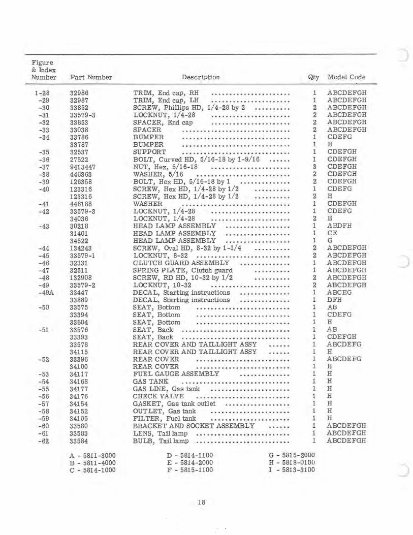
Figure & Index Number
1 -:28 -29 -30 -31 -32 - 33 - 34
- 35 - 36 - 37 -38 -39 -40
-41 - 42
- 43
-44 -45 -46 -47 -48 -49 -49A
-50
-51
-52
-53 -54 -55 -56 -57 -58 -59 -60 -61 - 62
Part Number
32986 32987 33852 33579 - 3 33853 33038 33786 33787 32537 27522 9413447 446363 126358 123316 123316 446188 33579- 3 34036 30218 31401 34522 134243 33579-1 32331 32511 132908 33579- 2 33447 33889 33575 33394 33604 33576 33393 33578 34115 33396 34100 34117 34168 34177 34176 34154 34152 34105 33580 33583 33584
A - 5811 - 3000 B - 5811 - 4000 C - 5814- 1000
Description
TRIM, End cap, RH •••••••••••••••••••••• TRIM, End cap, LH ••••••••.•.•.••.•••••• SCREW, Phillips HD, 1/4- 28 by 2 .••••.•••• LOCKNUT, 1/4- 28 •••.•.•••.•.•.•.••..•• SPACER, End cap •.•...•••••..•••••••.• SPACER ••.•••••.•••.•••••.••.•••..••• BUMPER ••••••.••••••••••••••.•..••••• BUMPER .••.•....••..•.••.•.....•..•.. SUPPORT •••••••••• . •••••••••• • •••••••. BOLT, Curved HD, 5/16- 18 by 1 - 9/16 NUT, Hex, 5/16- 18 •••••••••••••••••••••• WASHER, 5/16 ••.•••.••••••••••••••••..• BOLT, Hex HD, 5/16 - 18 by 1 •••••••••••.•• SCREW, Hex HD, 1/4- 28 by 1/2 •.••• •• ••• SCREW, Hex HD, 1/4- 28 by 1/2 •••• ••• ••• WASHER .••••••••••••••.••••••••• • •••• LOCKNUT, 1/4- 28 ••••••••.•.•.••••••••• LOCKNUT, 1/4- 28 ••.••••••••••••••••••• HEAD LAMP ASSEMBLY ••••.•••••.•••.•.• HEAD LAMP ASSEMBLY ••.•••.••••••••••• HEAD LAMP ASSEMBLY .•. . .•....•••..••• SCREW, OvaIHD, 8- 32 by 1-1/4 ••.••••••. LOCKNUT, 8- 32 .•• . .•.•. • •••••••••••••••• CLUTCH GUARD ASSEMBLY •••••••••••••• SPRING PLATE, Clutch guard .•.•.••••• SCREW, RD HD, 10 - 32 by 1/2 • .•••••••• LOCKNUT, 10- 32 .•.••••.••••.•.•••..•. DECAL, Starting instructions .•.••• . ••.•••. DECAL, Starting instructions .••••.•.•.•.•• SEAT, Bottom •••••••••••••••••••••••••• SEAT, Bottom ..•••••.••••••••••.•••.••• SEA T, Bottom .•••••••••••••••••••••••.• SEAT, Back ............................. . SEAT, Back •••••••••.•••••••••••••••••••• REAR COVER AND TAILLIGHT ASSY REAR COVER AND TAILLIGHT ASSY REAR COVER .••••••••••••••••••.•••••• REAR COVER ••••••••••••• • •••.•••••••• FUEL GAUGE ASSEMBLY •••••••••••••• GAS TANK .••••••••.••••.••••••••••••••• GAS LINE, Gas tank •.•..•••••.••••••••••• CHECK VALVE .••••••.•••.••.••••••••••• GASKET, Gas tank outlet .••••••••••••••••• OUT LET, Gas tank ...•.•••••••••••.••••• FIL TER, Fuel tank •••••••••••••••••••••• BRACKET AND SOCKET ASSEMBLY LENS, Taillamp ...................•...... BULB, Taillamp ..•••.•••••••••••••.••••••
Qty Model Code
1 ABCDEFGH 1 ABCDEFGH 2 ABCDEFGH 2 ABCDEFGH 2 ABCDEFGH 2 ABCDEFGH 1 CDEFG 1 H 1 CDEFGH 1 CDEFGH 3 CDEFGH 2 CDEFGH 2 CDEFGH 1 CDEFG 2 H 1 CDEFGH 1 CDEFG 2 H 1 ABDFH 1 CE 1 G 2 ABCDEFGH 2 ABCDEFGH 1 ABCDEFGH 1 ABCDEFGH 2 ABCDEFGH 2 ABCDEFGH 1 ABCEG 1 DFH 1 AB 1 CDEFG 1 H 1 AB 1 CDEFGH 1 ABCDEFG 1 H 1 ABCDEFG 1 H 1 H 1 H 1 H 1 H 1 H 1 H 1 H 1 ABCDEFGH 1 ABCDEFGH 1 ABCDEFGH
D - 5814-1100 E - 5814- 2000 F - 5815- 1100
G - 5815- 2000 H - 5818- 0100 I - 5813 - 3100
18
)
C Figure & Index Number
1 - 63 -64 - 65 - 66
-67 -68 - 69 - 70 -71
- 72 -73
-74 - 75 -76 -77 -78 - 79 -80 - 81 - 82
C -83 - 84 - 85
- 85A -86 - 87 -88 - 89 - 90 - 91
c
Part Number
34024 134190 33699 133063 133046 9414920 33647 33616 32252 33726-3 123316 33579-3 33774 33775 33777 33778 32234 181573 181577 181578 33579-3 33808 446188 34159 34271 34237 34555 34271 33867 181566 34000 34163 34155 34186
A - 5811 - 3000 B - 5811-4000 C - 5814- 1000
Description Qty
RIVET, 5/32 by 1/4 · ..... ................ 2 SCREW, Oval HD, 6- 32 by 1-1/ 4 · ......... 3 GROUND WIRE · ...... ................... 1 SCREW, RD HD, 1/ 4-20 by 2 · .. .. ... ...... 4 SCREW, RD HD, 1/4-20 by 7/ 8 · ....... .. 2 WASHER, Plain, 1/ 2 IN. OD · ............. 4 SPACER, Kickstand bumper · .. .. ......... 2 BUMPER, Kickstand · .... .. ... ........ ... . 2 PLA TE, Trailer hitch · .............. ... 1 SCREW, Truss HD, 1/4-28 by 1 - 1/2 3 SCREW, Truss HD, 1/4-28 by 1/2 · ......... 3 LOCKNUT, 1/4- 28 · ..................... 3 KICKSTAND ASSEMBLY · ...... ........... 1 KICKSTAND ASSEMBLY · ................ . 1 SPACER, Long · ......................... 2 SPACER, Short · .................. ....... 2 SPRING · ............... .................. 2 SCREW, Hex HD, 1/4-28 by 1-1/ 4 · ......... 2 SCREW, Hex HD, 1/4-28 by 1-3/4 · ......... 2 SCREW, Hex HD, 1/4-28 by 1-7/8 · ......... 2 LOCKNUT, 1/4-28 ...................... 6 WASHER, Formed · ..................... 4 WASHER .............................. 4 HOOD HOLDDOWN · ..................... 2 RIVET · .................................. 8 LATCH ASSEMBLY · ..................... 1 LATCH ASSEMBLY · ..................... 1 RIVET · ................................. 4 SUPPORT BRACE · ..................... 1 SCREW, Hex HD, 1/ 4 - 28 by 3/4 · ........ . 1 RUBBER STOP · ........... .............. 1 CLIP, Center holddown · ................. 2 STRAP, Holddown · ..................... 2 HOOK, Holddown strap · ................. 4
D - 5814- 1100 E - 5814- 2000 F - 5815 - 1100
G -- 5815 - 2000 H - 5813 - 0100 1 - 5813-3100
19
Model Code
ABCDEFGH ABCDEFGH ABCDEFGH ABCDEFG H BCEFG ABCDEFGH ABCDEFGH CDEFGH CDEFG H CDEFGH CDEFG H CDEFG CDEFGH CDEFGH CDEFGH CDEFGH CDEFGH CDEFGH CDEFGH CDEFGH ABCDEFGH ABCDEFGH ADFH BCEG ABCDEFGH A A ABCDEFGH ABCDEFGH ABCDEFGH ABCDEFGH
II 2 4
54 0 ~\ r ! 37 ~o .~-~ \ 35 36 39 ~ •
0 ' ~ .L, 0 3 ( :?J :~~" 33 ~\37~ 3841 ~
'{1 8~
91 88 J- 93 95 'l)6
J ';' ~~~ \" 89 \ 92 ,f
90
,:2~b~'U = ~/ 45/ 19 1 0~ j24 \ _ ' ____ -(20
'j;' ;:-/ 6f,..'l ~~1 100 16 ~ A 21 , 23
v 16 II 71 ~ y"'\ 'ef-ll 22'
7)fiJ. I. /I '" 58' 9B 105 ,~~fl' "'-" 78A~ cr~~82 _ I - 18~28~~ 18 \'\ '<" ,. '. I ~~- ~
'
80 81 . 7~;J79 I 69 ~'- ~ .. , 101
104 ~26 _ ] 110 84 ' ' --, 32~ 26A 0:
G - //81 "'- "'- ~~ ".. 81 ....... &, ' 5 ' " " /'1' . -' f"o 85 -ft ~ ~ > h 101 49 10& ['C_- ::-· ~" 21 109 I 8&~ ...... ,& 10 ~ ~03 &" 108
¥<Bl 'l1~ ~ 102 ...... "
51 V53~ 46 &---52 47
68
74 I r:--../
N 0 . _ .. - .. . . .. .
64
Hl11t -l\ ~~ ~ 1\ ~
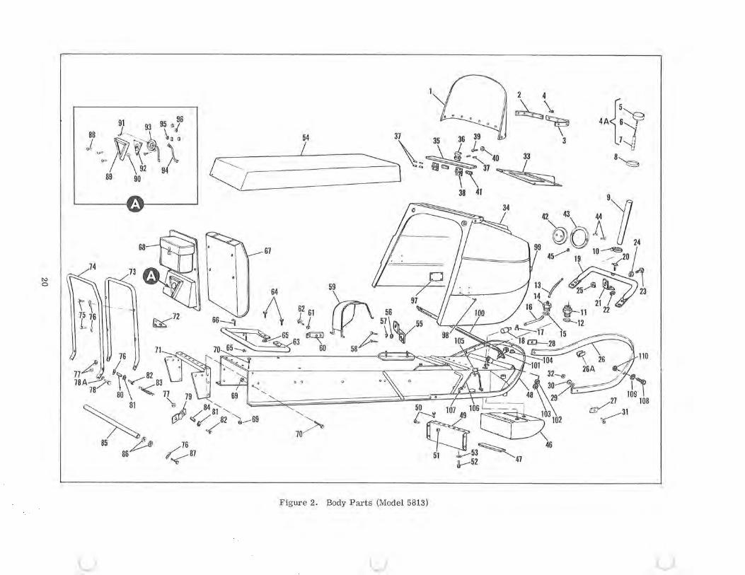
Figure 2. Body Parts (Model 5813)
u u u
c
c
c
Figure & Index Number
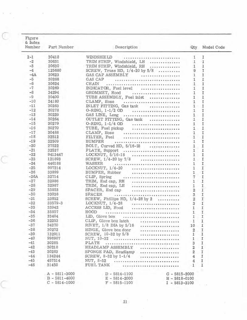
2-1 -2 -3 -4 -4A -5 -6 - 7 - 8 -9 -10 -11 -12 -13 -14 -15 -16 -17 -18 -19 -20 -21 -22 -23 -24 -25 - 26 -26A -27 -28 -29 -30 -31 -32 -33 -34 -35 -36 -37 -38 -39 -40 -41 -42 -43 -44 -45 -46
Part Number
30418 30631 30630 125680 30623 30268 30624 30269 34294 30400 24180 30263 30278 30229 30264 30279 30270 30488 32512 32509 27522 32537 9413447 121893 446188 997314 33899 32714 32986 32987 33853 33038 33852 33579-3 33942 33857 33404 32253 34270 30272 132911 996907 30285 30218 30283 134244 457514 31450
A - 5811-3000 B - 5811-4000 C - 5814-1000
Description
WINDSHIELD TRIM STRIP, Windshield, LH •.•••.•••••••• TRIM STRIP, Windshield, RH .••••••.••••. . SCREW, Truss HD, 1/4-20 by 5/8 •.......•• GAS CAP ASSEMBLY ••.••••.••••••••.. GAS CAP •••••••••••.•.•.•••••••••••••• CH AIN •••••••••••••••••••••••••••••••••• INDICATOR, Fuel level •••••••..•••.••••• GROMMET, Hood •••••••••••••••••••••. TUBE ASSEMBLY, Fuel inlet •••••••••••••• ClAMP, Hose ......................... . INLET FITTING, Gas tank •••••••••••••• O-RING, 1-1/2 OD •••••••••••••••••••••• GAS LIN"E, wng ...................•...... OUTLET FITTING, Gas tank •••••••••••••• O-RING, 1-1/4 OD •••••••••••••••••••••• TUBE, Fuel pickup •.•••••••••••••••••••• ClAMP, Hose ...............•..•....... FILTER, Fuel ..............•....•...... BUMPER ••.•.•.•.••••••••.•••••.•••.•• BOLT, CurvedHD, 5/16-18 •••••••••.•••• PLATE, Support .••••••••••••••••••.•••••• LOCKNUT, 5/16-18 ••.•.•••••••.•.•••• • •• SCREW, 1/4-20 by 7/8 ••.•••••.•.••••••. WASHER •••••••••••••••••••••••••••••• LOCKNUT, 1/4-20 •••..••••.•.•.••.•.••• BUMPER, Rubber ••.••••••••••••••••••• CLIP, Spring .•••••.••••.••.••••• • •••• • TRIM, End cap, RH •.•••••••••••••••••••• TRIM, End cap, LH •••••••••••••••••••••• SPACER, End cap ••.••••••••••.••.••.•• SPACER ....................... ., ..... . SCREW, Phillips HD, 1/4-28 by 2 .••••••••• LOCKNUT, 1/4-28 .•••••••••.••••••••••• ACCESS LID, H()od •••••••••••••.•••••••• HOOD ...............•... ............... LID, Glove box •••••••••••••••••••••••••• CLIP, Glove box latch ••••••.••••••••••• RIVET, 1/8 DIA by 5/16 ••••••••••••••.••• HINGE, Glove box door •••••••••••••••••• SCREW, 10-32 by 5/8 .•.•••••••••.•.••• NUT, 10 -3 2 •••••••• ••••••••.•••••••••• 0 ••
PIA TE ................................. . HEADLAMP ASSEMBLY ••..•••••••••••••• SPONGE PAD, Headlamp •••••••••••••••••• SCREW, 8-32 by 1-1/4 •••••••••••••••••• NUT, 8-32 ........ ..................... . FUE L TANK ••••••••••••••••••••••••••
Qty Model Code
1 I 1 I 1 I 9 I 1 I 1 I 1 I 1 I 1 I 1 I 1 I 1 I 1 I 1 I 1 I 1 I 1 I 1 I 1 I 1 I 1 I 1 I 1 I 1 I 1 I 1 I 1 I 7 I 1 I 1 I 2 I 3 I 2 I 3 I 1 I 1 I 1 I 1 I
10 I 2 I 1 I 1 I 3 I 2 I 2 I 4 I 4 I 1 I
D - 5814-1100 E - 5814-2000 F - 5815-1100
G - 5815-2000 H - 5818-0100 I - 5813 -3100
21
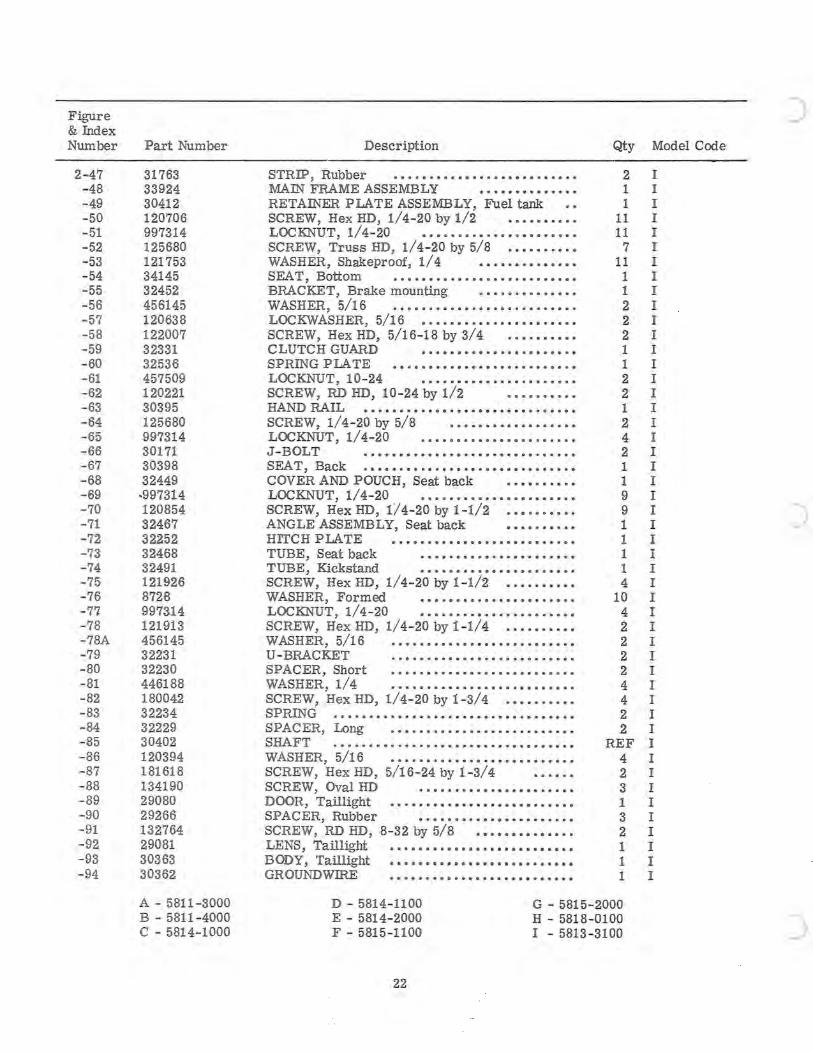
Figure & fudex Number
2-47 -48 -49 -50 -51 -52 -53 -54 -55 -56 -57 -58 -59 -60 -61 -62 - 63 -64 -65 -66 -67 -68 -69 -70 -71 -72 -73 -74 -75 -76 -77 -78 -78A -79 -80 -81 -82 -83 -84 -85 -86 -87 -88 -89 -90 -91 -92 - 93 -94
Part Number
31763 33924 30412 120706 997314 125680 121753 34145 32452 456145 120638 122007 32331 32536 457509 120221 30395 125680 997314 30171 30398 32449
·997314 120854 32467 32252 32468 32491 121926 8728 997314 121913 456145 32231 32230 446188 180042 32234 32229 30402 120394 181618 134190 29080 29266 132764 29081 30363 30362
A - 5811 -3000 B - 5811-4000 C - 5814-1000
Description
STRIP, Rubber ......................... . MAIN FRAME ASSEMBLY •••••••••••••• RETAINER PLATE ASSEMBLY, Fuel tank SCREW, Hex HD, 1/4-20 by 1/2 •••••••••• LOCKN"UT, 1/4-20 •••••••••••••••••••••• SCREW, Truss HD, 1/4-20 by 5/8 •••••..•.• WASHER, Shakeproof, 1/4 •••••••••••••• SEAT, Bottom ........................•. BRACKET, Brake mounting •••.•••••••••• WASHER, 5/16 •••••••••••••••••••••••••• LOCKWASHER, 5/16 •••••••••••••••••••••• SCREW, Hex HD, 5/16-18 by 3/4 •••••••••• CLUTCH GUARD •••••••••••••••••••••• SPRING p~ TE ••.•.•••••••.•.••.•.•.••.• LOCKNUT, 10-24 ••••••••••.•••.••••••• SCREW, RD HD, 10-24 by 1/2 .••••.•.•• HAND RAIL ...•.•.•...•.•..••..•.•...•... SCREW, 1/4-20 by 5/8 •••••••.•••••••••• LOCKNUT, 1/4-20 .•••••••••••••••.••••• J-BOLT ..•••••.••••••••••.•••••.••••• SEA T, Back ............................. . COVER AND POUCH, Seat back •••••••••• LOCKNUT, 1/4-20 •••••••••••••••••••••• SCREW, Hex HD, 1/4-20 by 1-1/2 •••••••••• ANGLE ASSEMBLY, Seat back •••••••••• HITCH PLATE •••••••••••••••••••••••••• TUBE, Seat back •••••••••••••••••••••• TUBE, Kickstand •••••••••••••••••••••• SCREW, HexHD, 1/4-20 by 1-1/2 •.•.•.•••• WASHER, Formed •••.••••••••••••••••.• LOC KN"UT , 1/4-20 •••••••••••••••••••••• SCREW, Hex HD, 1/4-20 by 1- 1/4 •••••••••• WASHER, 5/16 .•••••••••••••••••••••.•.• U -BRACKET ..•••••.•••••••••••••••••• SPACER, Short •••..•.•.••••••••••••••..• WASHER, 1/4 •••••••••••••••••••••••••. SCREW, Hex HD, 1/4-20 by 1-3/4 .••••.•••• SPRING .................•.........•...... SPAC ER, Long .••..••••••••••••..•••.••. SHAFT .•.•••••••••.•.•••••••••.•.•.••••• WASHER, 5/16 •.•.••••••.••.•••••••••.•• SCREW, Hex HD, 5/16-24 by 1-3/4 SCREW, Oval HD .•••••••••.••••••••••• DOOR, Taillight ••.••••••••••••••••••••••• SPACER, Rubber ••••••••.••••••••••••• SCREW, RD HD, 8-32 by 5/8 •••••••••••••• LENS, Taillight ......................... . BODY, Taillight ....•...........•.•....... GROUNDWffiE .••....••..••.••.•.•....•.
Qty Model Code
2 I 1 I 1 I
11 I 11 I
7 I 11 I
1 I 1 I 2 I 2 I 2 I 1 I 1 I 2 I 2 I 1 I 2 I 4 I 2 I 1 I 1 I 9 I 9 I 1 I 1 I 1 I 1 I 4 I
10 I 4 I 2 I 2 I 2 I 2 I 4 I 4 I 2 I 2 I
REF I 4 I 2 I 3 I 1 I 3 I 2 I 1 I 1 I 1 I
D - 5814-1100 E - 5814-2000 F - 5815- 1100
G - 5815-2000 H - 5818-0100 I - 5813-3100
22
)
)
C Figure & Index Number
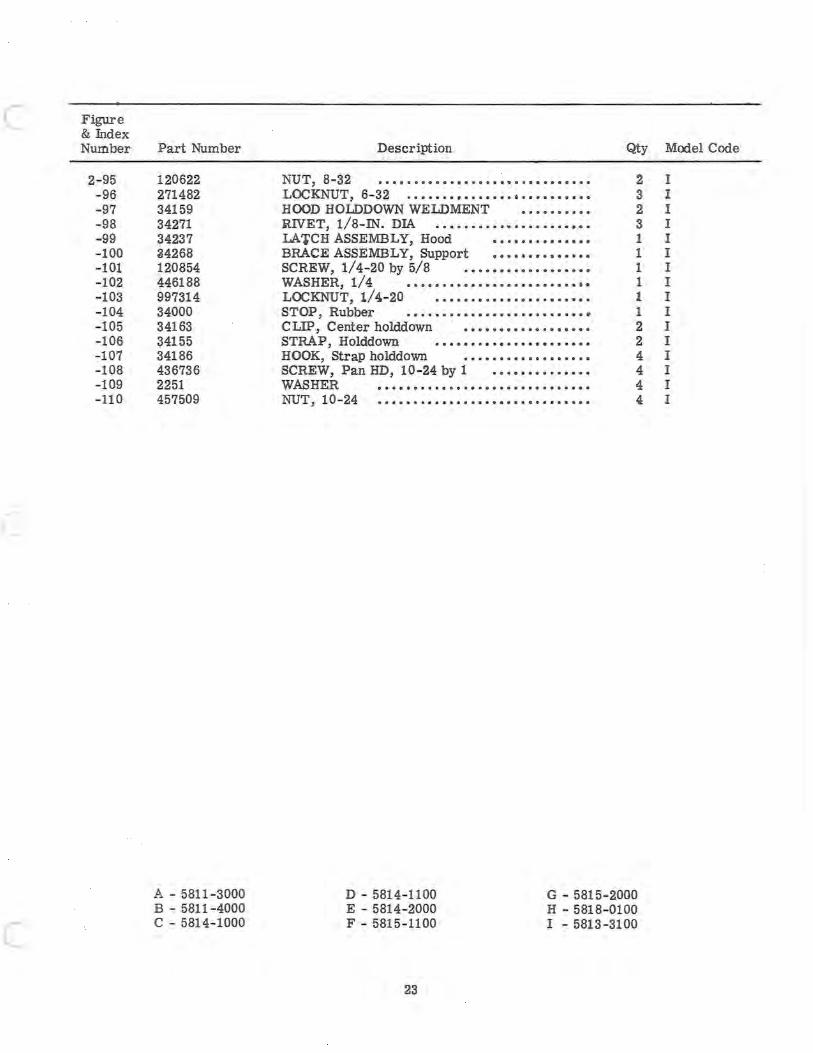
2- 95 -96 -97 -98 -99 -100 -101 -102 -103 -104 -105 -106 -107 -108 -109 -110
c
c
Part Number
120622 271482 34159 34271 34237 34268 120854 446188 997314 34000 34163 34155 34186 436736 2251 457509
A - 5811-3000 B - 5811-4000 C - 5814- 1000
Description Qty
NUT, 8-32 · ............................. 2 LOCKNUT, 6- 32 · ......................... 3 HOOD HOLDDOWN WELDMENT .......... 2 :RIVET, 1/8-IN. DIA · ..................... 3 LATCH ASSEMBLY, Hood · ............. 1 BRACE ASSEMBLY, Support · ............. 1 SCREW, 1/4-20 by 5/8 · ................. 1 WASHER, 1/4 · ......................... 1 LOCKNUT, 1/4.-20 · ..................... 1 STOP, Rubber · ......................... 1 CLIP, Center holddown · ................. 2 STRAP, Holddown · ..................... 2 HOOK, Strap holddown · ................. 4 SCREW, Pan HD, 10- 24 by 1 · ............. 4 WASHER · ............................. 4 NUT, 10-24 · ............................. 4
D - 5814- 1100 E - 5814-2000 F - 5815-1100
G - 5815-2000 H - 5818- 0100 I - 5813-3100
23
Model Code
I I I I I I I I I I I I I I I I
21 28 1 4 5 ./ 24
6 ~ _~ \1/~ ::-\~16 42 43 c1 1~:;n'J~ 25 36 1L 25_j-";? f 3//' 10 . ~~34 33
I 13-·./~ t 20
30 /1\ \ 11 13 11 r 12 4' 35---~ 8 I 13 7 15---=1 r~rl0 /
7 A 13 t ..,..-23?23
\: lX~2i' 40
Y- 13 /T1.-~ 10 1023
14-1/ \ 65~ 67 18 66:.:::=1-
9A 68A~ ~~~_ ____ l ", I ~/ ~4 ~ 00 "rr It" ~ iO'f" 50
'1 58 57
G ~
/ 83 84
70
- -----------;;;;;;~;:__;;;;;;:;;;;:_;~~~;;;;;;;-:~n;:Drive Elements F me and Top Skis, ra Figure 3. Steering,
24
)
c
c
c
Figure & Index Number
3-
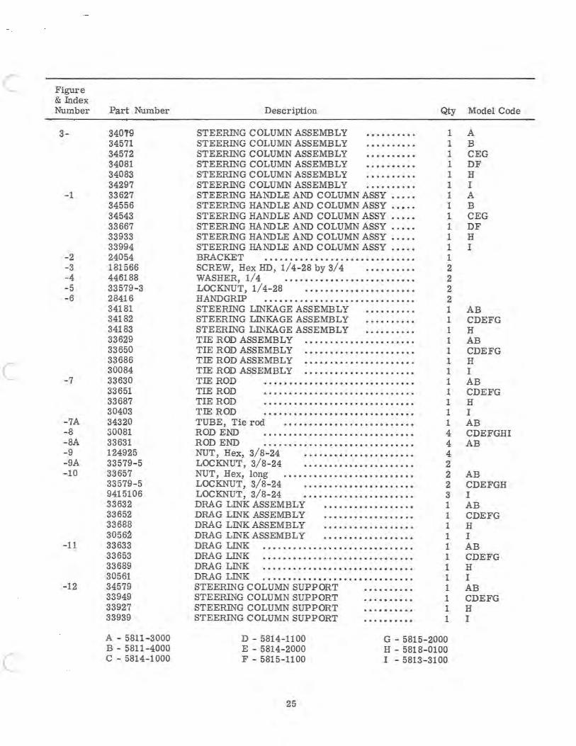
-1
-2 - 3 -4 -5 -6
-7
-7A -8 - 8A - 9 -9A - 10
-11
- 12
Part Number
34019 34571 34572 34081 34083 34297 33627 34556 34543 33667 33933 33994 24054 181566 44ti188 33579-3 28416 34181 34182 34183 33629 33650 33686 30084 33630 33651 33687 30403 34320 30081 33631 124925 33579 - 5 33657 33579-5 9415106 33632 33652 33688 30562 33633 33653 33689 30561 34579 33949 33927 33939
A - 5811-3000 B - 5811-4000 C - 5814- 1000
Description
STEERING COLUMN ASSEMBLY .••••••••. STEERING COLUMN ASSEMBLY •••••••••• STEERING COLUMN ASSEMBLY •••••••••• STEERING COLUMN ASSEMBLY •.•••••••• STEERING COLUMN ASSEMBLY •••••••••• STEERING COLUMN ASSEMBLY .••.•••••• STEERING HANDLE AND COLUMN ASSY ••••• STEERING HANDLE AND COLUMN ASSY •••.• STEERING HANDLE AND COLUMN ASSY •.•.• STEERING HANDLE AND COLUMN ASSY •.••• STEERING HANDLE AND COLUMN ASSY •.••. STEERING HANDLE AND COLUMN ASSY ••••• BRACKET •••••.•...•••...••••.••••••••• SCREW, Hex HD, 1/4- 28 by 3/4 •••••••.•• WASHER, 1/4 .••.•..•••••.••••••••••••• LOCKNUT, 1/4-28 .••.••..••••••••••••.• HANDGRIP .•.••.•.•.•.•••••....••••..••• STEERING LINKAGE ASSEMBLY •••••••..• STEERING LlliKAGE ASSEMBLY ..••.••••• STEERING LlliKAGE ASSEMBLY •.••••••.• TIE ROD ASSEMBLY ••.••.•.••••.••••••••• TIE ROD ASSEMBLY ••••••••.•.••••••••.•• TIE ROD ASSEMBLY •.•••.••.••..•.••••••. TIE ROD ASSEMBLY .•.•••••••••••••.•.••• TIE ROD ..•••.••••.•.•••.•••.••..•.••• TIE ROD •.•••••.•••••••••••••••••••... TIE ROD •••••••••••••••••••••••••••••• TIE ROD ......••••.•.••.•••.....•..... TUBE, Tie rod ••••••••.••••••••••••••.•• ROD END ••.••••••••••••••••••••••••••• ROD END ...... . .....•.••••.•.•••••• . •• NUT, Hex, 3/8-24 •••••••••.•••••••••••• LOCKNUT, 3/8- 24 •.•••• • ••••••••••••••• NUT, Hex, long •••••.•••.••••.••••••••••• LOCKNUT, 3/8-24 ••••••••••.••••••••••• LOCKNUT, 3/8-24 •••..•.•.••••.••••••.. DRAG LlliK ASSEMBLY ••.•..•••••••••••• DRAG LlliK ASSEMBLY •••••..•.••••••••• DRAG LlliK ASSEMBLY •••••••••.•.•••••• DRAG LINK ASSEMBLY .•••••.••••••••.•• DRAG LINK ..•.•....••.••••.••.•••••.•••. DRAG LlliK ....••••••.••.••.••••••••••••• DRAG LlliK .•.••.••••••••.•••••.••••••••• DRAG LlliK .••.••••.••••••••••••.•••••••• STEERING COLUMN SUPPORT •••••••••• STEERING COLUMN SUPPORT ••••••••.• STEERlliG COLUMN SUPPORT •••••••••• STEERING COLUMN SUPPORT ••••••••••
Qty Model Code
1 A 1 B 1 CEG 1 DF 1 H 1 I 1 A 1 B 1 CEG 1 DF 1 H 1 I 1 2 2 2 2 1 AB 1 CDEFG 1 H 1 AB 1 CDEFG 1 H 1 I 1 AB 1 CDEFG 1 H 1 I 1 AB 4 CDEFGHI 4 AB 4 2 2 AB 2 CDEFGH 3 I 1 AB 1 CDEFG 1 H 1 I 1 AB 1 CDEFG 1 H 1 I 1 AB 1 CDEFG 1 H 1 I
D - 5814-1100 E - 5814- 2000 F - 5815-1100
G - 5815-2000 H - 5818- 0100 I - 5813-3100
25
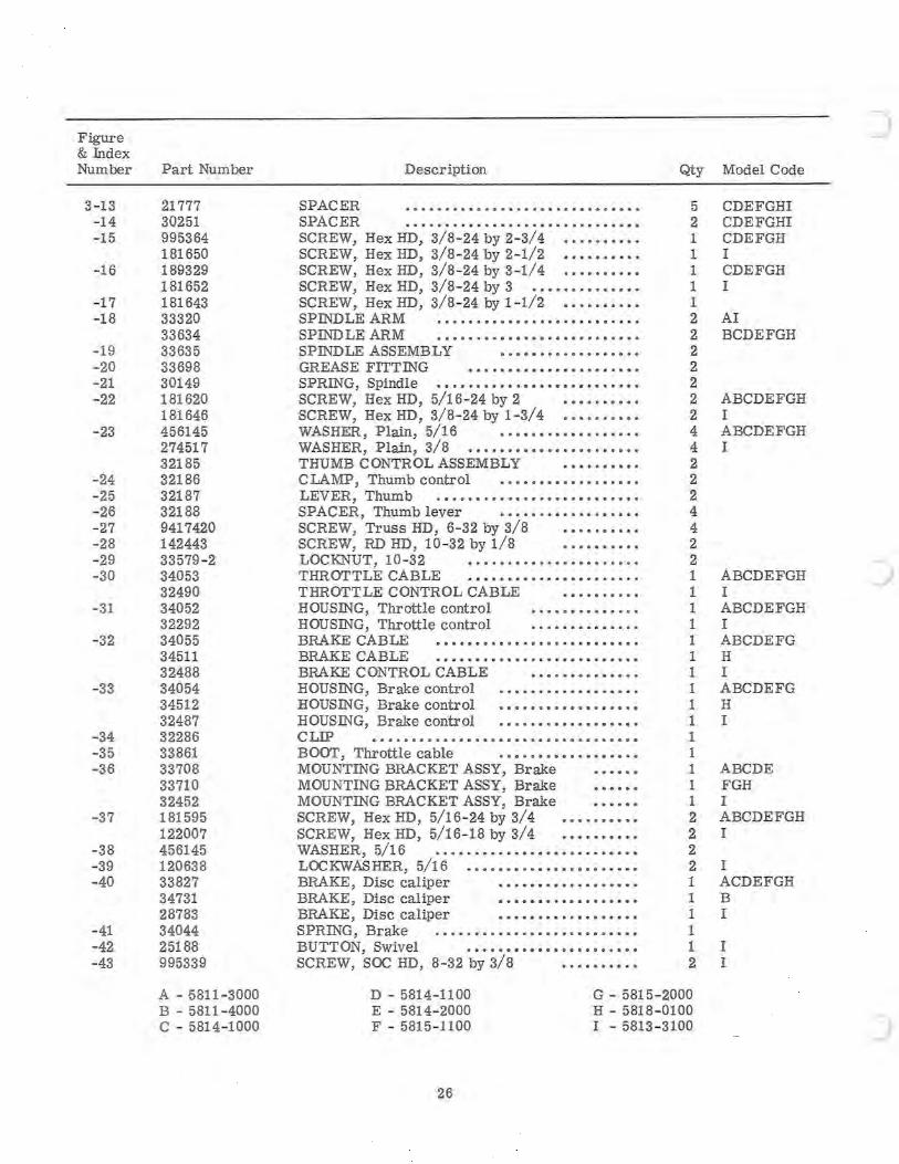
Figure & Index Number
3- 13 -14 - 15
- 16
- 17 - 18
-19 -20 -21 -22
-23
-24 -25 -26 -27 -28 -29 -30
- 31
- 32
-33
-34 -35 -36
-37
-38 -39 -40
-41 -42 -43
Part Number
21777 30251 995364 181650 189329 181652 181643 33320 33634 33635 33698 30149 181620 181646 456145 274517 32185 32186 32187 32188 9417420 142443 33579-2 34053 32490 34052 32292 34055 34511 32488 34054 34512 32487 32286 33861 33708 33710 32452 181595 122007 456145 120638 33827 34731 28783 34044 25188 995339
A - 5811-3000 B - 5811-4000 C - 5814- 1000
Description
SPACER .•••••••••••••••••• • • • ••••• • •• SPACER .......................•....•• SCREW, Hex HD, 3/8-24 by 2- 3/4 •••••••••• SCREW, Hex HD, 3/8-24 by 2-1/2 • • •••••••• SCREW, Hex HD, 3/8- 24 by 3-1/4 •••••••••• SCREW, Hex HD, 3/8- 24 by 3 •••••••••••••• SCREW, Hex HD, 3/8- 24 by 1 - 1/2 ••.••••••• SPlliDLE ARM .••••.••••••••••.•••••.•.• SPrnD LE ARM .••••••••••••••••••••••••• SPlliDLE ASSEMBLY ••••••••.••••••••• GREASE FITTlliG •••.••• • ••••••••••.••• SPRING, Spindle •••••••••••••••••••••••••• SCREW, Hex HD, 5/16 - 24 by 2 •••••••••• SCREW, Hex HD, 3/8- 24 by 1-3/4 •••••••••• WASHER, Plain, 5/16 •.•••••••••••••••• WASHER, Plain, 3/8 • • •••••••••••••••••••• THUMB CONTROL ASSEMBLY •••••••••• CLAMP, Thumb control •••••••••••••••••• LEVER, Thumb .•••••.••••••• • •••• • •••••• SPACER, Thumb lever •••••..••••••••••• SCREW, Truss HD, 6- 32 by 3/8 •••••••••• SCREW, RD HD, 10 - 32 by 1/8 •••••••••• LOCKNUT, 10-32 • . •••••.••.••.•••••••• THROTTLE CABLE .•• ••• • ••.•••••••.•••. THROTTLE CONTROL CABLE •••.•.•.•• HOUSlliG, Throttle control •••••••••••••• HOUSlliG, Throttle control .•.••••••••••• BRAKE CABLE ••••••••••••••••.••••••••• BRAKE CABLE .••• . •.•••••••• • •••••••••• BRAKE CONTROL CABLE •••••••••••••• HOUSlliG, Brake control •.•••••••••••••••. HOUSING, Brake control •••••••••••••••••• HOUSlliG, Brake control •••••••••••••••••• CLIP ................................. . BOOT, Throttle cable .••••••••••••••••• MOUNTING BRACKET ASSY, Brake MOUNTING BRACKET ASSY, Brake MOUNTING BRACKET ASSY, Brake SCREW, HexHD, 5/16- 24 by 3/4 • ••••••••• SCREW, Hex HD, 5/16- 18 by 3/4 ••••.••••• WASHER, 5/16 •••••••••••••••••••••••••• LOCKWASHER, 5/16 .••••••.•••••••••••••• BRAKE, Disc caliper •••••••••• •• •••••. BRAKE, Disc caliper •.•••••.•••••••••• BRAKE, Disc caliper •••••••••••••••••• SPRING, Brake .••••••••••••••••••••••••• BUTTON, Swivel ••••••••••••••••••.••• SCREW, SOC HD, 8- 32 by 3/8 ••••••••••
Qty Model Code
5 CDEFGHI 2 CDEFGHI 1 CDEFGH 1 I 1 CDEFGH 1 I 1 2 AI 2 BCDEFGH 2 2 2 2 ABCDEFGH 2 I 4 ABCDEFGH 4 I 2 2 2 4 4 2 2 1 ABCDEFGH 1 I 1 ABCDEFGH 1 I 1 ABCDEFG 1 H 1 I 1 ABCDEFG 1 H 1 I 1 1 1 ABCDE 1 FGH 1 I 2 ABCDEFGH 2 I 2 2 I 1 ACDEFGH 1 B 1 I 1 1 I 2 I
D - 5814- 1100 E - 5814-2000 F - 5815 - 1100
G - 5815 - 2000 H - 5818 - 0100 I - 5813 - 3100
26
)
)
c
c
c
Figure & Index Number
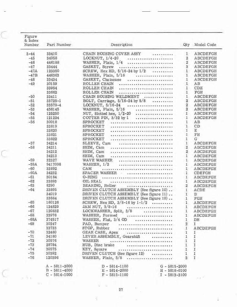
3-44 - 45 - 46 - 47 -47A - 47B -48 -49
-50 -51 -52 -53 -54 -55 - 56
- 57 - 58
- 59 - 59A - 60 - 60A -61 - 62 -63 -64
- 65 - 66 - 67 - 68 -68A - 69
- 70 -71 - 72 -73 - 74 -75 - 76
Part Number
33410 34058 446188 33444 123350 446363 33434 30159 33954 33662 33411 33725- 1 33579- 4 456145 125250 121224 30018 33819 33820 33821 33822 34214 34211 34212 34213 32327 9417098 33892 34232 30184 33893 8290 33895 34019 33684 180126 124829 120832 33976 274517 30247 33733 32480 34180 30576 28784 30575 30392 120396
A - 5811-3000 B - 5811 - 4000 C - 5814-1000
Descr iption
CHAIN HOUSING COVER ASSY .••....... LOCKNUT, 1/4-20 ..•••••••••••.•••••• . • WASHER, Plain, 1/4 •••..•••.••.••• • •.•••• GASKET, Screw .•••••.••••••••••••••••••• SCREW, Hex HD, 5/16-24 by 1/2 .•••••.•.. WASHER, Plain, 5/16 ................. . GASKET, Chaincase .. .•.••.••••.••.•••.•• ROLLER CHAIN •.••....•••••.••• . .••••••• ROLLER CHAIN ••••••••••••.•.••••••••••• ROLLER CHAIN .•.••••••••••••••••••••••• CHAIN HOUSING WELDMENT •••••••••••••• BOLT, Carriage , 5/16-24 by 5/8 • •• •.•.••. LOCKNUT, 5/16-24 •••••••••••••••••••••• WASHER, Plain, 5/16 ................ .. NUT, Slotted hex, 1/2-20 ................. . COTTER PIN, 3/32 by 1 ................ .. SPROCKET ••••••••• •• ••••••• • • •• •••••••• SPROCKET .•••••••..•.•••.•.•••..••••.•• SPROCKET •••.•••.••.•.•••.•••••••.•.••• SPROCKET •.•.•.•..•••••••.••.•••.•.•••• SPROCKET .••.•••••••.••.•.•...••••••••• SLEEVE, Cam • .••.••• .••.•• .• •••••••.•. SHIM, Cam •.••.•• . .•.••...•.•.••••••.••• SHIM, Cam ..•.••••••.•.••••.•••••••••••• SHIM, Cam . •• '" .••.•.•.•.•.•...•.•..•.• WAVE WASHER ••.•.•...•.••.•••.•.•.••.• WASHER, 1/2 .•.•..•..•..••.•..•••.••.• CAM ...•.....••.....•••.•.•• •••••. .••. SPACER WASHER .•.•.••.•.•.•••••••••• O-RING •••..•..•. . •.•.•••••...•.•••• . •••. OIL SEAL .•••..••.•••••••••••••.••.•.•• BEARING, Roller ••.•.•••.•..•.•••.••.• DRIVEN CLUTCH ASSEMBLY (See figure 10) .. DRIVEN CLUTCH ASSEMBLY (See figure 11) •• DRIVEN CLUTCH ASSEMBLY (See figure 10) •• SCREW, Hex HD, 3/8 - 16 by 1-1/2 •••••••••• JAM NUT, 3/8- 16 .................... .. LOCKWASHER, Split, 3/8 ••.•.•••••.••• WASHER, Formed ..•••••••••••••••••••• WASHER, Flat, 3/4 OD ................. . PAD, Bumper •••••••..••.•.....••...••. STOP , Rubber •••.•••••••••••••••••••••• GEAR CASE, Apex .•••••••••••••••.••.•• LEVER ASSEMBLY, Gears hift •••••••••• WASHER .••••••••••.••••••.••••••••••• HUB, Disc brake •••••••••••••••.•••••• KEY, Square ...•.••••••.•••••••••••••• DRIVEN CLUTCH (See figure 12) ••••••••.• WASHER, Plain, 3/8 •.••••••••••••.••••••.
Qty Model Code
1 ABCDEFGH 2 ABCDEFGH 2 ABCDEFGH 3 ABCDEFGH 1 ABCDEFGH 1 ABCDEFGH 1 ABCDEFGH 1 AB 1 CDE 1 FGH 1 ABCDEFGH 2 ABCDEFGH 2 ABCDEFGH 2 ABCDEFGH 1 ABCDEFGH 1 ABCDEFGH 1 AB 1 CD 1 E 1 FH 1 G 1 ABCDEFGH 2 ABCDEFGH 2 ABCDEFGH 1 ABCDEFGH 1 ABCDEFGH 1 ABCDEFGH 1 A BCDEFGH 1 CDEFGH 1 ABCDEFGH 1 ABCDEFGH 2 ABCDEFGH 1 ACDE 1 B 1 FGH 1 ABCDEFGH 1 ABCDEFGH 1 ABCDEFGH 1 ABCDEFGH 1 DH 2 I 1 ABCDEFGH 1 I 1 I 1 I 1 I 1 I 1 I 2 I
D - 5814- 1100 E - 5814- 2000 F - 5815- 1100
G - 5815-2000 H - 5818- 0100 I - 5813-3100
27

Figure & Index Number
3-77 - 78 -79 - 80 - 81 -82 - 83
-84 -85
-86
-87 -87A
-88
-89
-90
- 90A
-91
-92 -93
- 94 -95 - 96 -97
-98
-99 -100
Part Number
120382 120377 30535 180079 120638 8103 34037 34564 34563 34038 34006 33430 32466 30228 187044 995364 33579-5 32703 121222 33749 33747 32177 181639 995371 33579-5 995224 33750 33732 28769 33752 33728 32547 33751 33729 28770 33734 33730 29645 33731 32539 32540 33735 33296 28764 33748 32174 28762 144518 33297
A - 5811-3000 B - 5811-4000 C - 5814 - 1000
Description
LOCKWASHER, 3/8 •.•••••.•..•.••••••••• NUT, Hex HD, 3/8-16 ••••••••••••.•.••• KEY , HI-PRO, NO. 706 .••••••••••••••• 0 •
SCREW, 5/16-18 by 1 .••.•.•••.•.•••.•• LOCKWASHER, 5/16 •••••••••••••.•.••.••• WASHER, Flat, 5/16 ••••.•.•.••.•.•••••••• MAIN FRAME ASSEMBLY •.•.••.••••.•• MAIN FRAME ASSEMBLY •••••••••••••• MAIN FRAME ASSEMBLY .••••.••••••.• MAIN FRAME ASSEMBLY •••••••••••••• MAIN FRAME ASSEMBLY •••••••••••••• MAIN FRAME ASSEMBLY .••••••••••••• MAIN FRAME ASSEMBLY •••••••.•••.•. FOOT PAD ............................. . SCREW, Hex HD, 3/8-24 by 3-1/2 •••••••••. SCREW, Hex HD, 3/8-24 by 2-3/4 .••••••••. LOCKNUT, 3/8-24 •.•••••••••••••••••••• NUT, Slotted hex, 3/8-24 •••••••••••••••••• COTTER PIN •••••••••••••••••••••.•••• SKI AND SPRING ASSEMBLY ••••••.•••.••• SKI AND SPRING ASSEMBLY •••••••••••••• SKI AND SPRING ASSEMBLY •••••••••••••• SCREW, Hex HD, 3/8-24 by 1-1/4 .•.•.••••• SCREW, Hex HD, 3/8-24 by 3-1/2 .•••••••.• LOCKNUT, 3/8-24 .•••••••.••••••••••••. NUT, Slotted hex, 3/8-24 .••.••••.•••.••.•. BRACKET, Spring mounting •..••...•...•. BRACKET, Spring mounting •••••.•••.•••• BRACKET, Spring mounting •.••••..•••••• SKI SPRING ASSEMBLY .•.••.••.•.•..•.•• SKI SPRING ASSEMBLY •••••••••..••••••• SKI SPRING ASSEMBLY .••.••••••••.••••• LEAF SPRING ••••••.•.•••••••.•.•.•.••• LEAF SPRING, Main ••.••••••••••••••• •••. LEAF SPRING, Main ••••••••.••• .••.•••.• • LillER .........................•........ LEAF SPRING, Middle •..••••• •• .•• ; • • .• LEAF SPRING, Middle .•.•••••••••••••.• LEAF SPRING, Top •..••.••••••.•••.••• •• LEAF SPRING •••••••.•••.•••••••••• •••• LEAF SPRING .•••••..•••••.•••••.•••••• PLATE, Pressure .•••••.•••••••••.••.•• PLATE, Spring •••••••••••••••••••••• •••• PLATE, Spring .•...•.•..•••••.•••.•••••. PIVOT PIN, Spring .......•••.••.••.••••. PIVOT PIN, Spring, front •••••••••••••• PIVOT PIN, Spring, rear •••••••••••••••••• COTTER PIN •••••••••••••••••.•••••••• BUMPER, Rubber
Qty
2 2
REF 1 1 1
REF REF REF REF REF REF
1 2 2 2 2 2 4 2 2 2 4 4 4 4 2 2 2 2 2 2 2 2 2 2 2 2 2 2 2 2 2 2 2 2 2 2 2
D - 5814-1100 E - 5814-2000 F - 5815-1100
G - 5815-2000 H - 5818- 0100 I - 5813-3100
28
Model Code
I I I I I I AG B CE D F H I CDEFGHI ABCDEFGH I ABCDEFGH I I AB CDEFGH I ABCDEFGH I ABCDEFGH I AB CDEFGH I AB CDEFGH I AB CDEFGH I AB CDEFGH I CDEFGH I I AB CDEFGH I ABCDEFGH I
ABCDEFGH
)
C Figure & Index Number Part Number Description Qty Model Code
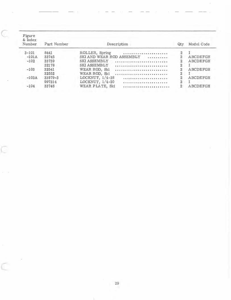
3- 101 8441 ROLLER, Spring •••••••••••••••••••••• 2 I - lOlA 33745 SKI AND WEAR ROD ASSEMBLY •••••••••• 2 ABCDEFGH - 102 33739 SKI ASSEMBLY .•.••.•••• • ••••.•••••••••• 2 ABCDEFGH
32178 SKI ASSEMBLY •••••••••••••••••••••••••• 2 I - 103 32541 WEAR ROD, Ski •••••••••••••••••••••••••• 2 ABCDEFGH
32552 - 103A 33579 - 3
WEAR ROD, Ski •••••••••••••••••••••••••• LOCKNUT, 1/4-28 ••••••••••••••••••••••
2 I 2 ABCDEFGH
997314 LOCKNUT, 1/4-20 •••••••••••••••• • •.••• 2 I - 104 33746 WEAR PLA TE, Ski ...............•....... 2 ABCDEFGH
c
c 29
62 ,\ 1" r- -j) ',~ \ '--\
61 60
58
~. _.'-~
59 61 60
~~~_~ \\ d 63
49
( --lr· 5:~~~ 6-----J. 109 108 107 "( 0 ' 56
12'-.. 7 , ...;12 ~J/57 ~' .. ' ,; , \iP'~~" 53 ' ,-"c:54
72 I ~ \ J; • 7 ~ I . ' 55 i /57 ,:::::: ' ,~ [ 71 ),., . - , ~
10~!74}73 1 _56
-;;;;-_ _ _ I I~~' ;:"'; 52 89 87
--- ' -.- --- / =;-( 75 __ ' I I , i ' (I ~-"'~ " -:;,, I( 10 ll-Jl I 90/ '1'.e' 88
77
' 11 75--=--e 82/''"'' d" 82 -... ~ 76~ ~ 71~~J7 lSA JU'· 81
70 lJ,.-71 788 I
lSC: ~~79 8f84~~78 ~ \ _ (" 84
83
~ ~~\),) 78E 85~ o~
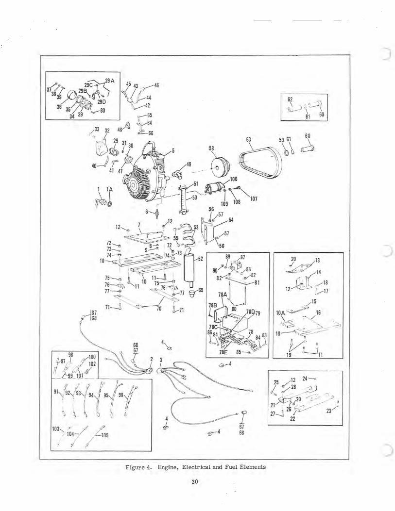
Figure 4. , ectr ical and F Engine El uel Elements
30
)
)
c
c
c
Figure & Index Number
4- 1 -lA -2
-3
-4 -5
-6
-7
-8
-9
-10
- lOA -11
- 12 -13 -14 - 15 -16 - 17
-18 -19 - 20 -21 -22 -23 -24 -25 -26
Part Number
33875 138561 33701 34107 33702 34207 34108 33610 34091 34092 33973 33972 33974 34047 34048 33864 30170 34602 33807 30170 33791 34062 33792 274517 274517 9416107 33579-5 33765 33765 34319 33725-3 33725-3 33579-4 33783 33780 33781 33782 180175 120426 120384 33725-5 33579-4 33929 33928 33864-18 120368 181610 456145
A - 5811-3000 B - 5811-4000 C - 5814-1000
Description
KEYSWITCH .......•.•.........•..•... LOCKWASHER, 3/4, internal ••••••••••.••• WIRING HARNESS, Hood •••••••••••••••••• WIRING HARNESS, Hood •••••••••••••••••• WIRING HARNESS, Engine •••••••••••••• WIRING HARNESS, Engine •.• .•••••••••• WIRING HARNESS, Engine •••••••••••••• CLIP, Wiring harness ••.••••.••••.••.•• ENGINE, JLO 292 ••••••••••• ••••••••••• ENGINE , JLO 227 ••••••••••••••••••.••• ENGINE, 297 PE •••.•.•••••••••.•••••• ENGINE, 297 E •••••••••••••••••••• •••••• ENGINE, 300 PE ••••••••.•..•••...•.•. ENGINE, 372 E .•.••••••••.•••••••••••••• ENGINE, 380 PE ••••••••••.•.••••••••• ENGINE, 400 E .•••••• •••••••• ••••••••.•. STUD, Engine base .•.••••••••.•.•••.•••• STUD, Engine base ••••.•..••••••••••••.• STUD, Engine base (used with 7/16-14 THD) •• STUD, Engine base (used wfth 10- MM, 1. 5 THD) ENGINE MOUNT ..•.••• ••••..••.••••.• .••• ENGINE MOUNT ••••••••••••.••••••••••••• ENGINE BASE •••••..•••..••.••••••..•.• WASHER, Flat, 3/8 .•••••.••••••••••••••• WASHER, Flat, 3/8 ••••••••.••••••••...•. LOCKNUT, 3/8-16 •••••••••••••••••••••• LOCKNUT, 3/8- 16 •••••••.•.•••••••••••• MOUNTING STRAP WELDMENT ••••.•.•.• MOUNTING STRAP WELDMENT ••••••..•. MOUNTING STRAP WELDMENT •••••••••• BOLT, Carriage, 5/16-24 by 1 •••••••••• BOLT, Carriage, 5/16-24 by 1 ••.••••••• LOCKNUT, 5/16- 24 •••••••••••••••••••••• TOP PLATE ••••••••••••••••••••••••.• CHANNEL ASSEMBLY •••••.•••••••••••• SPACER BAR •••••••••••••••••••••••••• ENGINE BASE PLATE ••••••••••••••.••• BOLT, Hex HD, 1/2- 13 by 1-1/4 ••••..•••• BOLT, Hex HD, 1/2-13 by 1 -1/4 •••••••••• LOCKWASHER, Split, 1/2 •••••••••.•••. BOLT, Carriage, 5/16-24 by 1- 1/2 LOCKNUT, 5/16-24 .•.••••••••••••.•••••• ENGINE MOUNT, LH •.••••••••.••••••• ENGINE MOUNT, RH •••..••••••••••••• SCREW, Hex HD, 8 MM by 9 MM •••••••••• LOCKWASHER, 5/16 .••..••••••••••.•••••• SCREW, Hex HD, 5/16-24 by 1- 1/4 WASHER, Flat .••••••••••••.••••••••.•••
Qty Model Code
1 ABCDEFGH 1 ABCDEFGH 1 ABCDEFG 1 H 1 ABCDEF 1 G 1 H 4 ABCDEFGH 1 A 1 B 1 C 1 D 1 E 1 F 1 G 1 H 4 A 4 B 4 CDE 4 C 1 A 1 B 1 CD 4 ABCDE 2 F 4 ACE 4 BD 2 ABCE 1 FG 1 FG 4 ABCDE 2 FG 4 ABCDEFGH 1 FG 1 FG 1 FG 1 FG 4 F 4 G 4 FG 2 FG 2 H 1 H 1 H 2 H 2 H 2 H 2 H
D - 5814-1100 E - 5814-2000 F - 5815-1100
G - 5815-2000 H - 5818-0100 I - 5813-3100
31
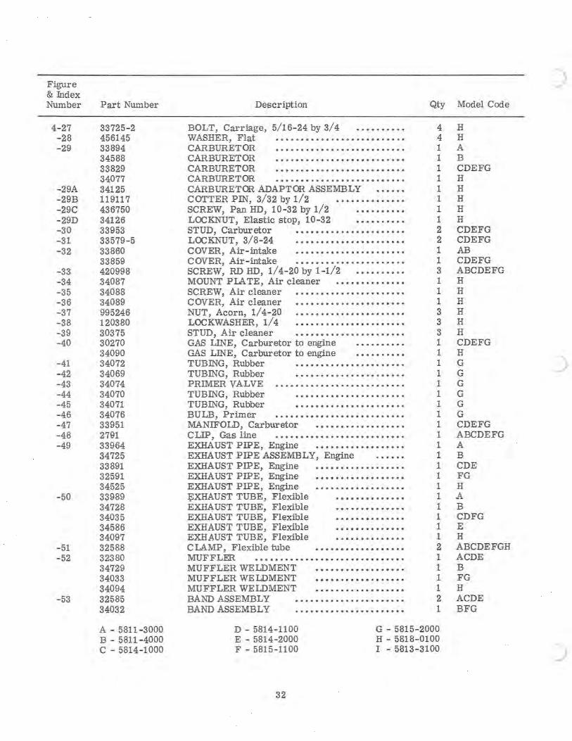
Figure & Index Number
4-27 -28 -29
-29A -29B -29C -29D -30 -31 -32
-33 -34 -35 -36 -37 -38 -39 -40
-41 -42 -43 -44 -45 -46 -47 -48 -49
-50
-51 -52
-53
Part Number
33725-2 456145 33894 34588 33829 34077 34125 119117 436750 34126 33953 33579-5 33860 33859 420998 34087 34088 34089 995246 120380 30375 30270 34090 34072 34069 34074 34070 34071 34076 33951 2791 33964 34725 33891 32591 34525 33989 34728 34035 34586 34097 32588 32380 34729 34033 34094 32585 34032
A - 5811-3000 B - 5811-4000 C - 5814-1000
Description
BOLT, Carriage, 5/16-24 by 3/4 •.••...••. WASHER, Flat •••••••••••••••••••••••••• CARBURETOR ..••••••••••.•••••••.••••. CARBURETOR •••.•••••••••••••••••••••• CARBURETOR •••••••••••••••••••••••••• CARBURETOR •••••••••••••••••••••••••• CARBURETOR ADAPTOR ASSEMBLY COTTER PIN, 3/32 by 1/2 •••••••••••••• SCREW, Pan HD, 10-32 by 1/2 •••••••••• LOC KNUT, Elastic stop, 10 -3 2 •••••.•••• STUD, Carburetor •••••••••••••••••••••• LOCKNUT, 3/8-24 •••••••••••••••••••••• COVER, Air-intake •••••••••••••••••••••• C OVER, Air-intake •••.•.•••••••••••.•••• SCREW, RD HD, 1/4-20 by 1-1/2 •••••••••• MOUNT PIA TE, Air cleaner .••••••••••••• SCREW, Air cleaner •••••••••••••••••••••• COVER, Air cleaner •••••••••••••••••••••• NUT, Acorn, 1/4-20 •••••••••••••••••••••• LOCKWASHER, 1/4 •••••••••••••••••••••• STUD, Air cleaner •••••••••••••••••••••• GAS LINE, Carburetor to engine •••••••••• GAS LINE, Carburetor to engine •••••.•••• TUBING, Rubber •••••••••••••••••••••• TUBING, Rubber •.••••••••••••.••••••• PRIMER VALVE ...•••.••••.•••••••••••.•. TUBING, Rubber .••••••••••.•••••.•.•. TUBING, Rubber ••••••••••••••••.••••• BU LB, Primer •••••••••••••••••••••••••• MANIFOLD, Carburetor •••••••••••••••••• CLIP, Gas line ••••••••••••.••••••••••••. EXHAUST PIPE, Engine ••••••••••••••••.• EXHAUST PIPE ASSEMBLY, Engine EXHAUST PIPE, Engine •••••••••••••••••• EXHAUST PIPE, Engine •••••••••••••••••• EXHAUST PIPE, Engine •••••••••••••••••• ~XHAUST TUBE, Flexible •••••••••••••• EXHAUST TUBE, Flexible •••••••••••••• EXHAUST TUBE, Flexible •••••••••••••• EXHAUST TUBE, Flexible •••••••••••••• EXHAUST TUBE, Flexible •.•••••••••••• CLAMP, Flexible tube •••••••••••••••••• MUF FLER •••••••••••••••••••••••••••••. MUFFLER WELDMENT •••••••••••••••••• MUFFLER WE LDMENT •••••••••••••••••• MUFFLER WELDMENT •••••••••••••••••• BAND ASSEMBLY •••••••••••••••••••••• BAND ASSEMBLY •.••••••••••••••••••••
Qty Model Code
4 H 4 H 1 A 1 B 1 CDEFG 1 H 1 H 1 H 1 H 1 H 2 CDEFG 2 CDEFG 1 AB 1 CDEFG 3 ABCDEFG 1 H 1 H 1 H 3 H 3 H 3 H 1 CDEFG 1 H 1 G 1 G 1 G 1 G 1 G 1 G 1 CDEFG 1 ABCDEFG 1 A 1 B 1 CDE 1 FG 1 H 1 A 1 B 1 CDFG 1 E 1 H 2 ABCDEFGH 1 ACDE 1 B 1 FG 1 H 2 ACDE 1 BFG
D - 5814-1100 E - 5814-2000 F - 5815-1100
G - 5815 - 2000 H - 5818-0100 I - 5813 - 3100
32
)
)
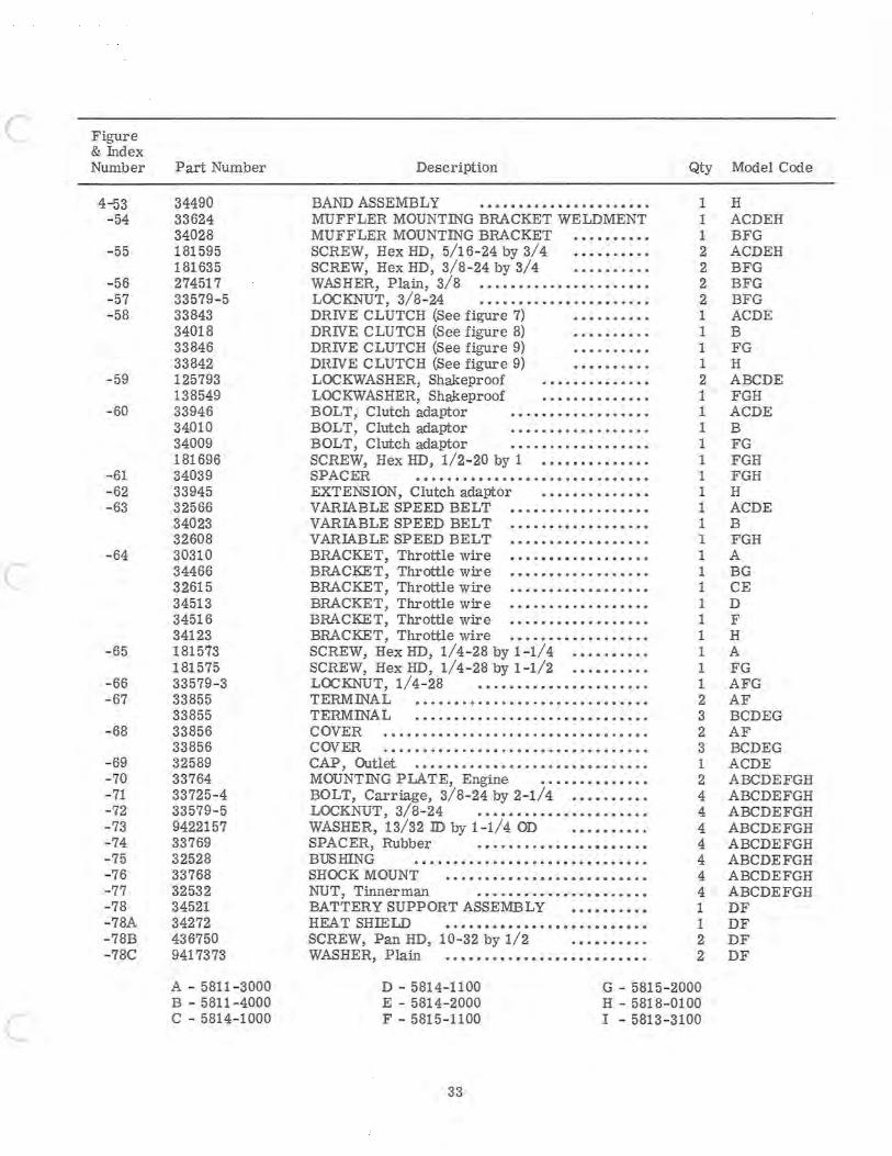
c
c
c
Figure & Index Number
4-53 - 54
- 55
- 56 - 57 -58
-59
-60
-61 -62 -63
-64
-65
-66 -67
-68
-69 -70 -71 -72 - 73 -74 -75 - 76 -77 -78 -78A - 78B -78C
Part Number
34490 33624 34028 181595 181635 274517 33579-5 33843 34018 33846 33842 125793 138549 33946 34010 34009 181696 34039 33945 32566 34023 32608 30310 34466 32615 34513 34516 34123 181573 181575 33579 - 3 33855 33855 33856 33856 32589 33764 33725-4 33579-5 9422157 33769 32528 33768 32532 34521 34272 436750 9417373
A - 5811-3000 B - 5811-4000 C - 5814-1000
Description
BAND ASSEMBLY •••••••••••••••••••••• MUFFLER MOUNTING BRACKET WELDMENT MUFFLER MOUNTING BRACKET ••••••••.• SCREW, HexHD, 5/16-24 by 3/4 .••.•••••• SCREW, Hex HD, 3/ 8-24 by 3/4 . ••••••••• WASHER, Plain, 3/8 ••••••••••••••.•••.••• LOCKNUT, 3/8-24 ••••.•••••.••••••••.•• DRIVE CLUTCH (See figure 7) •••••••••• DRIVE CLUTCH (See figure 8) •••••••••• DRIVE CLUTCH (See figure 9) •••••••••• DRIVE CLUTCH (See figure 9) •••••.•••• LOCKWASHER, Shakeproof .••••••••••••• LOCKWASHER, Shakeproof •••••••••••••• BOLT, Clutch adaptor ••.•••••••••••.••• BOLT, Clutch adaptor •••••••••••••••••• BOLT, Clutch adaptor .••••.•••••••••••• SCREW, Hex HD, 1/2- 20 by 1 •••••••••••••. SPACER •••••••••••••••••••••••.•••••• EXTENSION, Clutch adaptor •.•••••••.•••• VARIABLE SPEED BELT •••••••••••.•••••• VARIABLE SPEED BELT .•.•••.••••••••••• VARIABLE SPEED BELT ••.•••••••••••••.. BRACKET, Throttle wire .•••••••. 0 ••••••••
BRACKET, Throttle wire •••••••.•••••••..• BRACKET, Throttle wire ••••••••••• 0 0 •••••
BRACKET, Throttle wire .••.••• 0 • 0 ••••••••
BRACKE T, Throttle wire .••••••.••••••••• • BRACKET, Throttle wire . 0 ••••••••••••••••
SCREW, Hex HD, 1/4-28 by 1-1/4 ••••• 0 ••••
SCREW, Hex HD, 1/4- 28 by 1 -1/2 ••. 0 ••••••
LOCKNUT, 1/4- 28 ••.••••••••••••••••••• TERMINAL •..•.•...•.••••.•.•••••••••••• TERMINAL •.•.••.•••••••••••.••••••••••. COVER .•••••.•.•••.••.•••.•••••••••••••. COVER .•••••••••.••••.•••• 0 ••• 0 ••• 0 •••••
CAP, Outlet ••••••••••••••.••• 0 ••• 0 0 • 0 ••••
MOUNTING PLATE, Engine •••.•••••• 0 •••
BOLT, Carriage, 3/8 -24 by 2-1/4 ••• 0 ••••••
LOCKNUT, 3/8-24 .•••••••••••••••••••• 0
WASHER, 13/32 ill by 1-1/4 OD • 0.00 •••••
SPACER, Rubber .•..••••• 0 ••••• 0 ••••••
BUSHING •••••••••••••••••••••••••••••• SHOCK MOUNT ••••.••• 0 ••• 0 •••••• 0 ••••••
NUT, Tinnerman •••.•••••• 0 0 ••• 0 ••••••
BATTERY SUPPORT ASSEMBLY 0 •• 0 ••• 0 ••
HEAT SHIELD o ••••••••••••••••••• 0 •••••
SCREW, Pan HD, 10-32 by 1/2 .0.0 ••• 0 ••
WASHER, Plain ...•......•.•••.••.•......
Qty Model Code
1 H 1 ACDEH 1 BFG 2 ACDEH 2 BFG 2 BFG 2 BFG 1 ACDE 1 B 1 FG 1 H 2 ABCDE 1 FGH 1 ACDE 1 B 1 FG 1 FGH 1 FGH 1 H 1 ACDE 1 B 1 FGH 1 A 1 BG 1 CE 1 D 1 F 1 H 1 A 1 FG 1 AFG 2 AF 3 BCDEG 2 AF 3 BCDEG 1 ACDE 2 ABCDEFGH 4 ABCDEFGH 4 ABCDEFGH 4 ABCDEFGH 4 ABCDEFGH 4 ABCDEFGH 4 ABCDEFGH 4 ABCDEFGH 1 DF 1 DF 2 DF 2 DF
D - 5814-1100 E - 5814-2000 F - 5815 - 1100
G - 5815-2000 H - 5818-0100 I - 5813-3100
33
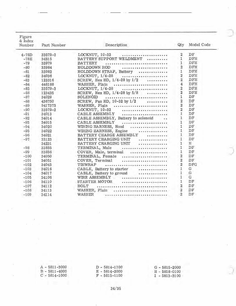
Figure & Index Number
4-78D -78E -79 -80 -81 -82 -83 -84 - 85 -86 -87 -88 -89 -90 -91 -92 -93 -94 -95 -96 -97
-98 -99 - 100 -101 -102 - 103 - 104 -105 -106 -107 -108 -109
Part Number
33579-2 34515 33979 33984 33982 34036 123316 446188 33579-3 123435 34029 436750 9417373 33579 - 2 34013 34014 34015 34020 34022 34021 33123 34231 33855 33856 34050 34051 34045 34016 34017 34106 34110 34112 34113 34114
A - 5811 -3000 B - 5811 - 4000 C - 5814- 1000
Description
LOCKNUT, 10 - 32 •.•••••••••••••••••••• BATTERY SUPPORT WELDMENT •••••••••• BATTERY .•....•....••.•...••.•• •...... HOLDDOWN ROD .•.••••••••••••••••••• HOLDDOWN STRAP, Battery ••••••••••••• • LOCKNUT, 1/4- 28 ••.•••••••••••••••••.• SCREW, Hex HD, 1/4- 28 by 1/2 •••••••••• WASHER, Plain ••••.•.••••••••••••••••••• LOCKNUT, 1/4-28 .••••••••••••••••••••• SCREW, Hex HD, 1/4-28 by 5/8 •• •••••.•• SOLENOID .................•............ SCREW, Pan HD, 10 -32 by 1/2 •••••••••• WASHER, Plain •••••••••••••••••••••••.•• LOCKNUT, 10-32 •••••••••••••••••.•••• CABLE ASSEMBLY •••••••••.•••.•••••••• CABLE ASSEMBLY, Battery to solenoid CABLE ASSEMBLY .••••••••••••••••••••• WIRING HARNESS, Hood .•.••.•.••••.•••.• WIRING HARNESS, Engine •••••••.•••.•• BATTERY CHARGE ASSEMBLY ••.•.••••• BATTERY CHARGING UNIT .•.•.•....•..• BA TTERY CHARGING UNIT •.•••••••••• .• TERMINAL, Male .••••••••••.•••••••••. COVER, Male, terminal .•••.•.••..••.•••• TERMINAL, Female .•.•••.•.•••.•..•••..• COVER, Terminal .•••••••••••••.••••.•. TIEWRAP •.••••.••••••••••••••••••••.•• CABLE, Battery to starter .••••••••••••• CABLE, Battery to ground •••.•••••.•••• WIRE ASSEMBLY ••.••••••••••••••••••• STARTER MOTOR •.••••••••.•••••••.••. BOLT ••••••.••••••.••••••••••••••.••••. WASHER, Plain •.•••••••••••••••••••••••• WASHER •.••.•.•...•••••••.•••.•••••••
Qty Model Code
2 DF 1 DFH 1 DFH 2 DFH 1 DFH 2 DFH 2 DFH 4 DFH 2 DFH 2 DFH 1 DF 2 DF 2 DF 2 DF 1 DF 1 DF 1 DF 1 DF 1 DF 1 DF 1 DF 1 H 1 DF 1 DF 2 DF 2 DF 2 DFG 1 G 1 G 1 G 1 DF 2 DF 2 DF 2 DF
D - 5814-1100 E - 5814- 2000 F - 5815 - 1100
G - 5815-2000 H - 5818-0100 I - 5813-3100
34/35
)
)

1
c
c
c
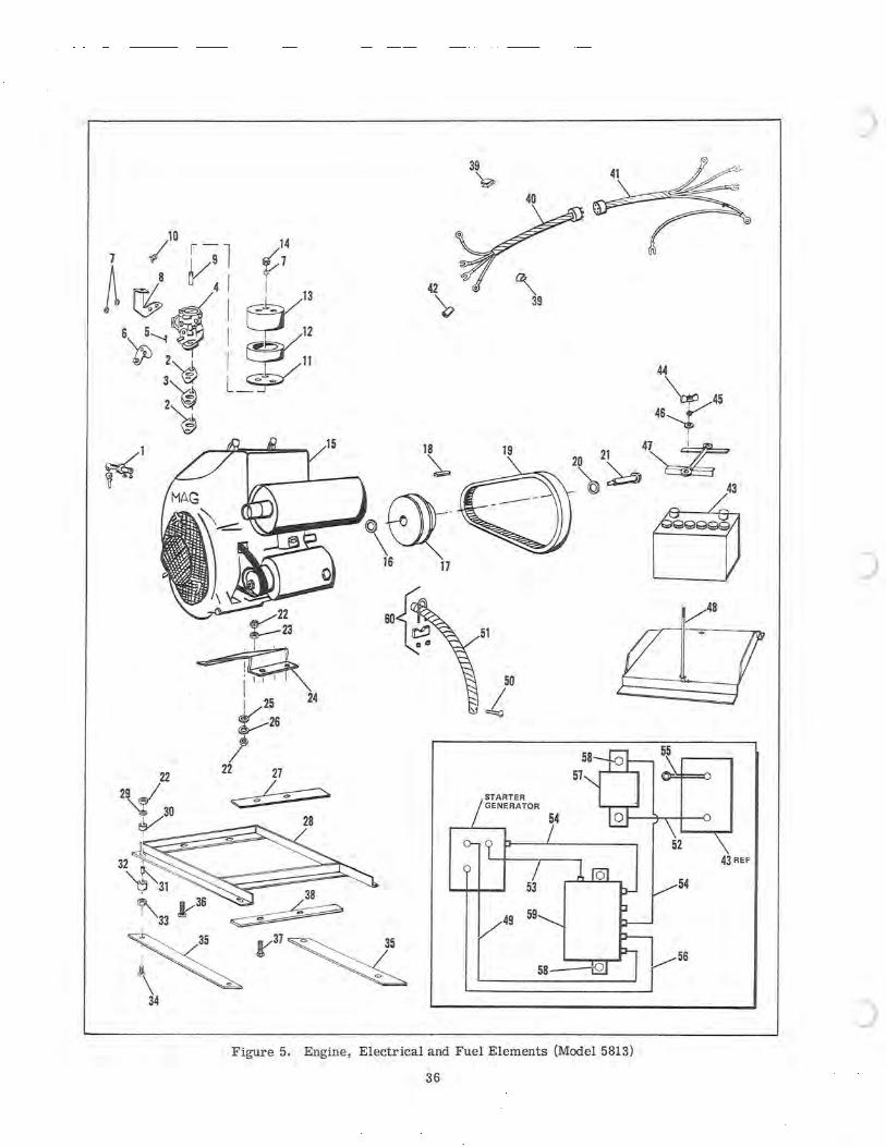
42
\>
18
~
~\~ 16 17
~22 ,;;....-23
~ I 25 24
~26 !
22 22 27
29fFa/ ~ ~30 ~
~28
~' ~ 32
\9~31 ~ ~ 36 "" 38 : 33l-' ~
K~~~ 34
39 'g,
~ 39
44
~V45 46~
I
19 21 4~ ~ 20 ~ ~~ c 43
cj 48
51
Figure 5. Engine, Electrical and Fuel Elements (Model 5813)
36
)
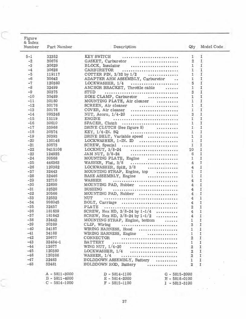
c
c
Figure & Index Number
5-1 -2 - 3 -4 -5 -6 -7 -8 -9 -10 -11 -12 -13 -14 - 15 -16 -17 -18 -19 - 20 - 21 -22 -23 -24 -25 - 26 - 27 -28 -29 -30 -31 - 32 -33 -34 -35 - 36 -37 - 38 - 39 -40 - 41 -42 -43 -44 -45 -46 -47 -48
Part Number
32352 30676 30629 30628 119117 30642 120380 32499 30375 30489 30180 30176 30178 995246 15119 30610 33968 30574 30393 130148 30573 9415106 124925 30568 446363 120382 32443 32446 32710 32699 32528 30566 32532 998045 32457 181639 181643 32442 30389 34187 34188 29677 32484-1 12677 120380 120386 32483 32481
A - 5811 - 3000 B - 5811-4000 C - 5814-1000
Description
KEY SWITCH GASKET, Carburetor •••••••••••••••••• BLOCK, Insulator •••••••••••••••••••••• CARBURETOR •••••••••••••••••••••••••• COTTER Pili, 3/32 by 1/2 ••••••• ••••• •• ADAPTER ARM ASSEMBLY, Carburetor LOCKWASHER, 1/4 •.•••••••••••••••••••• ANCHOR BRACKET, Throttle cable STUD ................................. . HOSE CLAMP, Carburetor •••••••••••••• MOUNTiliG PLATE, Air cleaner •••••••••• SCREEN, Air cleaner .••••••••••••.•.•• COVER, Air cleaner •••••••••••••••••••••• NUT, Acorn, 1/4-20 •••••••••••••••••••••• ENGINE ••••.•.••••••••.••••••••••••.• SPACER, Clutch •••••••••••••••••••••••••• DRIVE CLUTCH (See figure 9) •••••••.•• KEY, 1/4-ili. SQ •.••••••••••••••.••••. DRIVE BELT, Variable speed •••••••••••••• LOCKWASHER, I - IN. ID .••.•••••••••••••• SCREW, Special • ••• ••••••••••.••••••••••• LOCKNUT, 3/8- 24 •••••.•••••••••.•••••• JAM NUT, 3/8- 24 ..•••••••••.••••••.••• MOUNTING PLATE, Engine ••••.••••••••• WASHER, Flat, 3/8 .....•••••.•.•.••••••• LOCKWASHER, Split, 3/8 •.•••••••••••• MOUNTING STRAP, Engine, top ••.••••.•• BASE ASSEMBLY, Engine •••••••••.•••• WASHER ••.• . •••••••••••••••.••••••••• MOUNTING PAD, Rubber •••••••••••••••••• BUSHING .••..••.•.•.••.••••••••••••••• MOUNTING PAD, Rubber •••••••••••••••••• NUT .......•.•.•••••..•......••...•••. BOLT, Carriage ••.•••.••••.•••.•.•••••••• PLATE .•••••.••••••••••••••••••••.•••••• SCREW, Hex HD, 3/ 8-24 by 1 -1/4 ••••.••••• SCREW, Hex HD, 3/8-24 by 1-1/2 .••••••••• MOUNTING STRAP, Engine, bottom CLIP, Wiring .••••••••••••••••••••••••• WIRiliG HARNESS, Hood ••••.••••••••••••• WIRING HARNESS, Engine •••••••••••••• CONNECTOR .••••••••••••••••••••••••• BA TTERY •••••••••••••••••••••••••••••• WING NUT, 1/4- 20 •••••••••••••••••••••• LOCKWASHER, 1/4 •••••••••••••••••••••• WASHER, 1/4 •••••.•••••••••••••••••••• HOLDDOWN ASSEMBLY, Battery •••••••••• HOLDDOWN ROD, Battery ••••••••••••••
Qty Model Code
1 I 2 I 1 I 1 I 1 I 1 I 5 I 1 I 3 I 1 I 1 I 1 I 1 I 3 I 1 I 1 I 1 I 1 I 1 I 1 I 1 I
10 I 6 I 1 I 4 I 4 I 1 I 1 I 4 I 4 I 4 I 4 I 4 I 4 I 2 I 4 I 4 I 1 I 3 I 1 I 1 I 2 I 1 I 2 I 2 I 2 I 1 I 2 I
D - 5814- 1100 E - 5814-2000 F - 5815-1100
G - 5815-2000 H - 5818-0100 I - 5813-3100
37
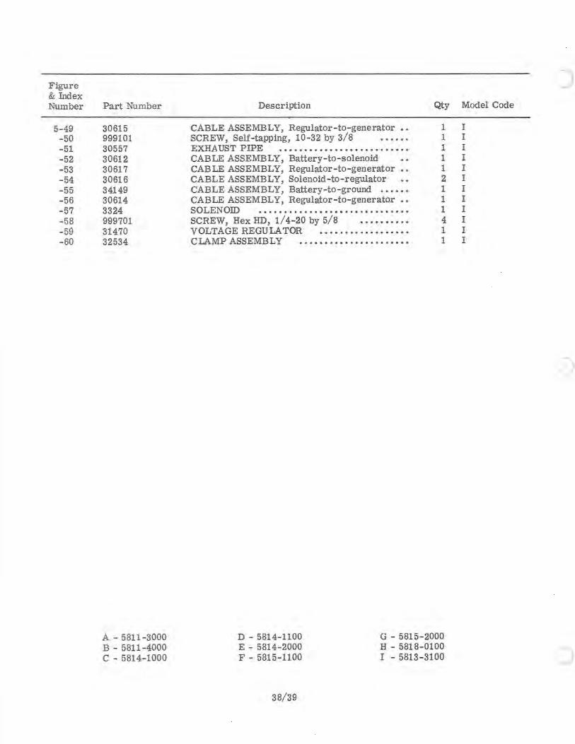
Figure & Index Number
5- 49 -50 -51 -52 -53 -54 -55 -56 -57 -58 -59 -60
Part Number
30615 999101 30557 30612 30617 30616 34149 30614 3324 999701 31470 32534
A - 5811-3000 B - 5811-4000 C - 5814-1000
Description
CABLE ASSEMBLY, Regulator-to-generator SCREW, Self-tapping, 10-32 by 3/8 EXHA UST PIPE ••••• ••••••••••••••••••••• CABLE ASSEMBLY, Battery-to-solenoid CABLE ASSEMBLY, Regulator-to -generator •• CABLE ASSEMBLY, Solenoid - to-regulator CABLE ASSEMBLY, Battery-to-ground •••••• CABLE ASSEMBLY, Regulator-to-generator •• SOLENOID .•••••••••••••••••••.••••••••• SCREW, Hex HD, 1/4-20 by 5/8 •••••••••• VOLTAGE REGULA TOR ••••••••••••••.••• CLAMP ASSEMBLY ..••••••••••••• •••• ••.
Qty Model Code
1 I 1 I 1 I 1 I 1 I 2 I 1 I 1 I 1 I 4 I 1 I 1 I
D - 5814-1100 E - 5814-2000 F - 5815-1100
G - 5815-2000 H - 5818-0100 I - 5813-3100
38/39
)
)

c
c
c
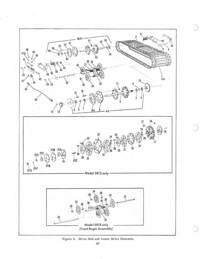
4A------~
27C 278 27A@ 270 Q
\~ @G)~yt~ 1G 27F 278
Model 5813 only ------~
34
36 ~36 34 'k~ . - ~ 34
35 ~36 39 40 3~ ~ 3~ \ '11 ~A- ~ @_ -Il.?
30 1
~J 33
Model 5818 I (Front B _ on y ogle Assembly)
Figure 6 . Drive Belt :~::::-;:=-~----and Low er Drive El 40 ements --- I
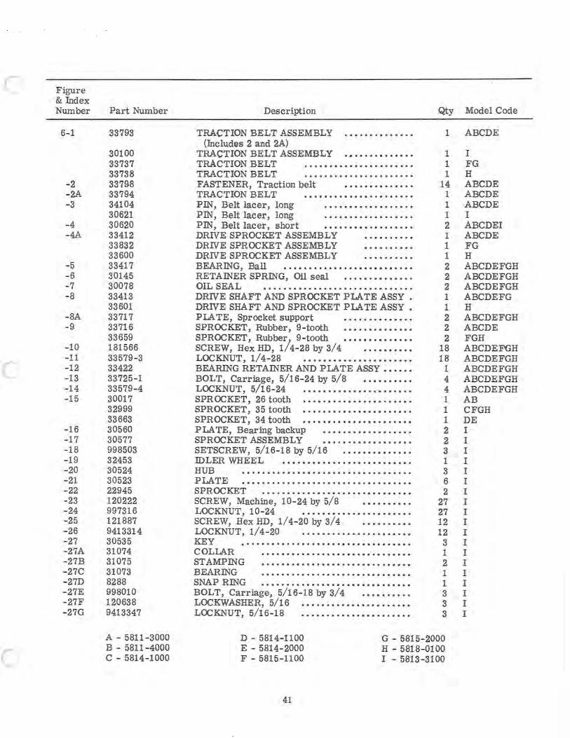
c
c
c
Figure & Index Number
6-1
-2 -2A -3
-4 -4A
-5 -6 -7 -8
-8A -9
-10 -11 -12 -13 -14 -15
-16 -17 -18 -19 -20 -21 - 22 -23 -24 -25 - 26 -27 -27A -27B - 27C -27D -27E -27F -27G
Part Number
33793
30100 33737 33738 33798 33794 34104 30621 30620 33412 33832 33600 33417 30145 30078 33413 33601 33717 33716 33659 181566 33579-3 33422 33725- 1 33579 - 4 30017 32999 33663 30560 30577 998503 32453 30524 30523 22945 120222 997316 121887 9413314 30535 31074 31075 31073 8288 998010 120638 9413347
A - 5811 - 3000 B - 5811-4000 C - 5814-1000
Description
TRACTION BELT ASSEMBLY ••••••.•••••.• (Includes 2 and 2A)
TRACTION BELT ASSEMBLY ••••••••••••.. TRACTION BELT •.•••••••••••••••••••• TRACTION BELT •••.••.••.••.•.••.•••. FASTENER, Traction belt .••••••••••••. TRACTION BELT ••.••.•••.••••.•••.••. PIN, Belt lacer, long .••.•••••••••••••• PIN, Belt lacer, long .••••.•.•••••.•••. PIN, Belt lacer, short ••••••••..•••.•••• DRIVE SPROCKET ASSEMBLY •.•••...•• DRIVE SPROCKET ASSEMBLY •••••••••• DRIVE SPROCKET ASSEMBLY •••••...•• BEARING, Ball •••••••••••••••••••••••••• RETAINER SPRING, Oil seal •.•••.••••••.. OIL SEAL ••••••••••..••••••.••••••••••• DRIVE SHAFT AND SPB.OCKET PLATE ASSY • DRIVE SHAFT AND SPROCKET PLATE ASSY • PLA TE, Sprocket support ••••••••.•••.. SPROCKET, Rubber, 9 -tooth .••••••••••••• SPROCKET, Rubber I 9-tooth •••••••••••.•• SCREW, Hex HD, 1/4-28 by 3/4 ..••••.••• LOCKNUT, 1/4- 28 •••••••••••••••••••••• BEARING RETAINER AND PLATE ASSY ••••.• BOLT, Carriage, 5/16-24 by 5/8 •••••••••• LOCKNUT, 5/16-24 .••••••••.••.•.••••••• SPROCKET, 26 tooth .•.•.••••••••.•••••••• SPROCKET, 35 tooth •.•.••••••••••••••.•.• SPROCKET, 34 tooth .•.••••••••••••••••••• PLATE, Bearing backup ••••.•.••••••••••• SPROCKET ASSEMBLY •••.•••••••••••••• SETSCREW, 5/16-18 by 5/16 ••.•••••••.••• IDLER WHEEL ......................... . HUB .........•...•..............•••... PLATE ••••••••••••••••••••••.•.•..•••••• SPROCKET .•••••.•••.•.•••••.•.••.• .••••• SCREW, Machine, 10 - 24 by 5/8 •••••••••• LOCKNUT, 10 - 24 ..•.•••••••••..••••••• SCREW, Hex HD, 1/4- 20 by 3/4 .•••..•••• LOCKNUT, 1/4-20 .....•..••.•••..•••.•• KEY •••••••••..••••••••••.•••••••••••. COLLAR ..••••••••••.•••.••.••.•..•.•• STAMPING ••••••••••••••••.••••••••••••• BEARING •••••••.•.•..•.••••••.•••••••• SNAP RING •••••••••••••••••••••••••••••• BOLT, Carriage, 5/16-18 by 3/4 .••••••••. LOCKWASHER, 5/16 •••.•.•••••••••••••••• LOCKNUT, 5/16-18 .•.••.•••••••••••.••..
Qty Model Code
1 ABCDE
1 I 1 FG 1 H
14 ABCDE 1 ABCDE 1 ABCDE 1 I 2 ABCDEI 1 ABCDE 1 FG 1 H 2 ABCDEFGH 2 ABCDEFGH 2 ABCDEFGH 1 ABCDEFG 1 H 2 ABCDEFGH 2 ABCDE 2 FGH
18 ABCDEFGH 18 ABCDEFGH
1 ABCDEFGH 4 ABCDEFGH 4 ABCDEFGH 1 AB 1 CFGH 1 DE 2 I 2 I 3 I 1 I 3 I 6 I 2 I
27 I 27 I 12 I 12 I
3 I 1 I 2 I 1 I 1 I 3 I 3 I 3 I
D - 5814- 1100 E - 5814-2000 F - 5815-1100
G - 5815-2000 H - 5818-0100 I - 5813-3100
41
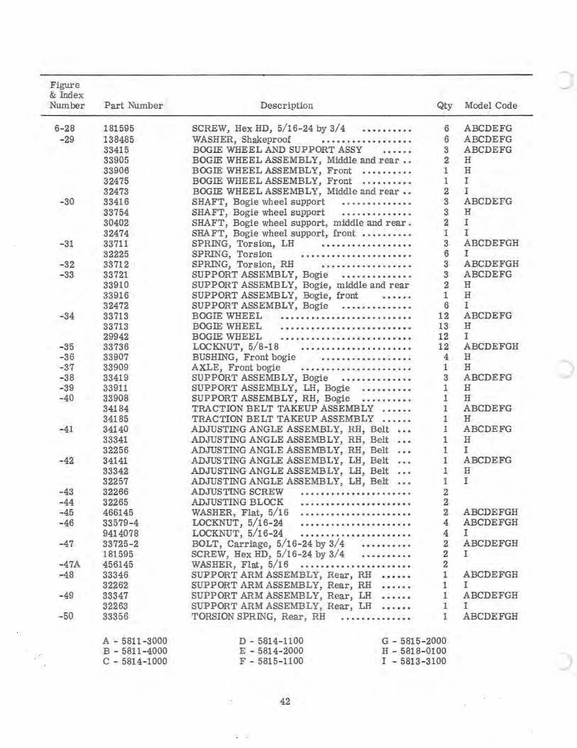
Figure & Index Number
6- 28 -29
-30
- 31
- 32 - 33
- 34
-35 - 36 - 37 - 38 - 39 -40
- 41
- 42
-43 -44 -45 - 46
-47
- 47A -48
- 49
- 50
Part Number
181595 138485 33415 33905 33906 32475 32473 33416 33754 30402 32474 33711 32225 33712 33721 33910 33916 32472 33713 33713 29942 33736 33907 33909 33419 33911 33908 34184 34185 34140 33341 32256 34141 33342 32257 32266 32265 466145 33579 - 4 9414078 33725- 2 181595 456145 33346 32262 33347 32263 33356
A - 5811-3000 B - 5811 - 4000 C - 5814- 1000
Description
SCREW, Hex HD, 5/16-24 by 3/4 •••• • •• • •• WASHER, Shakeproof •••••••••••••••••• BOGIE WHEEL AND SUPPORT ASSY BOGIE WHEEL ASSEMBLY, Middle and rear •• BOGIE WHEEL ASSEMBLY, Front •••••••••• BOGIE WHEEL ASSEMBLY, Front •••••••••• BOGIE WHEEL ASSEMBLY, Middle and rear •• SHAFT, Bogie wheel support • • •••••••••••• SHAFT, Bogie wheel support •••••••••.•.•• SHAFT, Bogie wheel support, middle and rear. SHA FT, Bogie wheel support, front •••••••••• SPRING, Torsion, LH •••••.•.•••••••••• SPRING, Torsion ••••••••••••.••••••••• SPRING, Torsion, RH ••••••.•.••••••••• SUPPORT ASSEMBLY, Bogie •••••••••••••• SUPPORT ASSEMBLY, Bogie, middle and rear SUPPORT ASSEMBLY, Bogie, front SUPPORT ASSEMBLY, Bogie •••••••••••••• BOGIE WHEEL •••••••••••••••••••••••••• BOGIE WHEEL .••••••.••••••.••••••••••• BOGIE WHEEL •••••..•.••••••••••••••••• LOCKNUT, 5/8-18 •••••••••••••••••••••• BUSHING, Front bogie •••••••••••••• • ••• AXLE, Front bogie •••••••••••••••••••••• SUPPORT ASSEMBLY, Bogie •••••••••••••• SUPPORT ASSEMBLY, LH, Bogie •••.•.•.•• SUPPORT ASSEMBLY, RH, Bogie •••••••••• TRACTION BELT TAKEUP ASSEMBLY •••••• TRACTION BELT TAKEUP ASSEMBLY .••••• ADJUSTING ANGLE ASSEMBLY, RH, Belt ADJUSTING ANGLE ASSEMBLY, RH, Belt ADJUSTING ANGLE ASSEMBLY, RH, Belt ADJUSTING ANGLE ASSEMBLY, LH, Belt ADJUSTING ANGLE ASSEMBLY, LH, Belt ADJUSTING ANGLE ASSEMBLY, LH, Belt ADJUS TING SCREW •••••••••••••••••••••• ADJUSTING BLOCK ••.••••••••••••••••••• WASHER, Flat, 5/16 •••••.•••••••••••••••• LOCKNUT, 5/16- 24 •••••••••••••••••••••• LOCKNUT, 5/16- 24 •••••••••••••••••••••• BOLT, Carriage, 5/16-24 by 3/4 •••••••••• SCREW, Hex HD, 5/16-24 by 3/4 •••••••••• WASHER, Flat, 5/16 •••••••••••••••••••••• SUPPORT ARM ASSEMBLY, Rear, RH SUPPORT ARM ASSEMBLY, Rear, RH SUPPORT ARM ASSEMBLY, Rear, LH •••••• SUPPORT ARM ASSEMBLY, Rear, LH •••••• TORSION SPRING, Rear, RH .•.•••••••••••
Qty Model Code
6 ABCDEFG 6 ABCDEFG 3 ABCDEFG 2 H 1 H 1 I 2 I 3 ABCDEFG 3 H 2 I 1 I 3 ABCDEFGH 6 I 3 ABCDEFGH 3 ABCDEFG 2 H 1 H 6 I
12 ABCDEFG 13 H 12 I 12 ABCDEFGH 4 H 1 H 3 ABCDEFG 1 H 1 H 1 ABCDEFG 1 H 1 ABCDEFG 1 H 1 I 1 ABCDEFG 1 H 1 I 2 2 2 ABCDEFGH 4 ABCDEFGH 4 I 2 ABCDEFGH 2 I 2 1 ABCDEFGH 1 I 1 ABCDEFGH 1 I 1 ABCDEFGH
D - 5814-1100 E - 5814- 2000 F - 5815- 1100
G - 5815 - 2000 H - 5818-,0100 I - 5813 - 3100
42
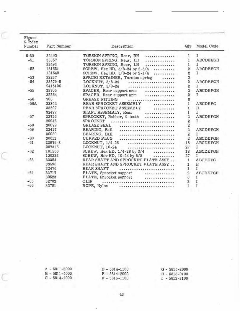
C Figure & Index Number
6-50 - 51
- 52
-53 - 54
-55
-56 - 56A
- 57
-58 -59
- 60 - 61
C - 62
- 63
- 64
- 65 - 66
c
Part Number
32492 33357 32493 181651 181649 32237 33579-5 9415106 33705 32264 706 33352 33597 32477 33716 29945 30079 33417 30080 30611 33579-3 997316 181566 120222 33354 33598 32476 33717 30523 32702 32701
A - 5811 - 3000 B - 5811 - 4000 C - 5814-1000
Description Qty
TORSION SPRING, Rear, RH · ............. 1 TORSION SPRING, Rear, LH · ............. 1 TORSION SPRING, Rear, LH · ............. 1 SCREW, Hex HD, 3/8- 24 by 2- 3/4 · ......... 2 SCREW, Hex HD, 3/8- 24 by 2-1/4 · ... ...... 2 SPRING RETAINER, Tors ion spring 2 LOCKNUT, 3/8- 24 · ..................... 2 LOCKNUT, 3/8- 24 · ..................... 2 SPACER, Rear support arm · ............. 2 SPACER, Rear support arm · ............. 2 GREASE FITTING · ..................... 6 REAR SPROCKET ASSEMBLY · ......... 1 REAR SPROCKET ASSEMBLY · ......... 1 SHAFT ASSEMBLY, Rear · ............. 1 SPROCKET, Rubber, 9-tooth · ............. 2 SPROCKET .............................. 2 GREASE SEAL · .......................... 2 BEARING, Ball · ......................... 2 BEARING, Ball · ......................... 2 CUPPED PLUG · ......................... 2 LOCKNUT, 1/4- 28 · ..................... 18 LOCKNUT, 10- 24 · ..................... 27 SCREW, Hex HD, 1/4- 28 by 3/4 · ......... 18 SCREW, Hex HD, 10- 24 by 5/8 · ......... 27 REAR SHAFT AND SPROCKET PIA TE ASSY •• 1 REAR SHAFT AND SPROCKET PIATE ASSY •• 1 REAR SHAFT · ......................... 1 PLATE, Sprocket support · ............. 2 PLATE, Sprocket support · ............. 6 CLIP .................................. 2 ROPE, Nylon · ......................... 1
D - 5814-1100 E - 5814- 2000 F - 5815 - 1100
G - 5815 - 2000 H - 5818 -0100 I - 5813-3100
43
Model Code
I ABCDEEGH I ABCDEFGH I
ABCDEFGH I ABCDEFGH I
ABCDEFG H I ABCDEFGH I
ABCDEFGH I ABCDEFGH ABCDEFGH I ABCDEFGH I ABCDEFG H I ABCDEFGH I I I
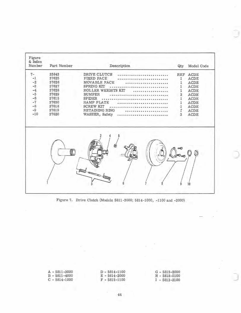
Figure & Index Number
7--1 - 2 -3 -4 - 5 -6 -7 -8 -9 -10
Part Number
33843 37625 37626 37627 37628 37629 37615 37630 37618 37619 37620
,
Description
DRIVE CLUTCH ••••••••••.••••••••••••••• FIXED FACE •••••••• •••••••••••••• •••• MOVABLE FACE •••••••••••••••••••••• SPRING KIT •.••• • ••••••••• •••.•••••••• • •• ROLLER WEIGHTS KIT ••••• ••••••••••••• BUMPER . •.••••••••••••••••• •••••• •••• SPIDER •••••••••••••.••••••• ••••• •••••••• RAMP PLATE ••••••.•.••••••••••••••••• SCREW KIT •••••••••••.•••••.•••••.•••••• RETAINING RING ••••••••••••••••••.••• WASHER, Safety •••••.••••••••••••••••••••
2 4
r--
~ 3 6
Qty
REF 1 1 1 1 3 1 1 1 t 3
Figure 7. Drive Clutch (Models 5811 -3000; 5814- 1000, -1100 and -2000)
A - 5811 -3000 B - 5811-4000 C - 5814 - 1000
D - 5814- 1100 E - 5814-2000 F - 5815-1100
"44
G - 5815-2000 H - 5818- 0100 I - 5813-3100
Model Code
ACDE ACDE ACDE ACDE ACDE ACDE ACDE ACDE ACDE ACDE ACDE
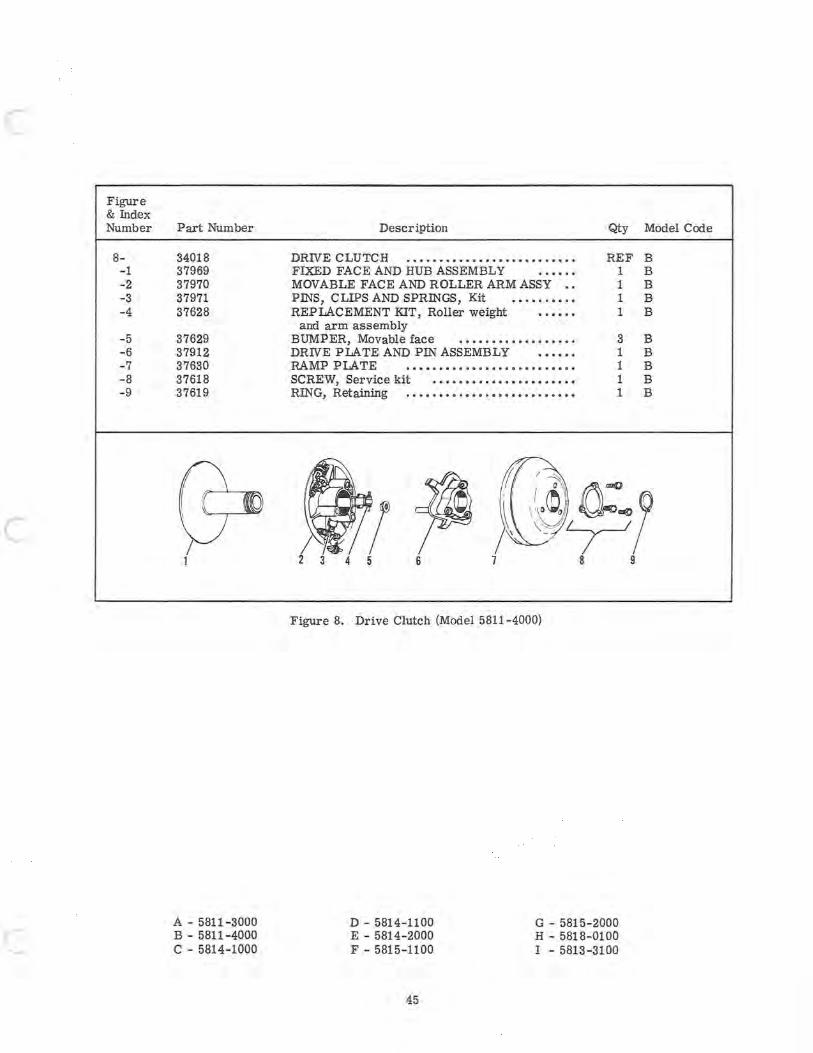
c
Figure & Index Number
8--1 -2 -3 -4
-5 -6 -7 -8 -9
c
c
Part Number
34018 37969 37970 37971 37628
37629 37912 37630 37618 37619
A - 5811-3000 B - 5811 - 4000 C - 5814-1000
Description Qty
DRNE CLUTCH · ......................... REF FIXED FACE AND HUB ASSEMBLY 1 MOVABLE FACE AND ROLLER ARM ASSY .. 1 PINS, CLIPS AND SPRINGS, Kit .......... 1 REPLACEMENT KIT, Roller weight 1
and arm assembly BUMPER, Movable face .................. 3 DRNE PLATE AND PIN ASSEMBLY 1 RAMP PLATE · ......................... 1 SCREW, Service kit ...................... 1 RING, Retaining · ......................... 1
3 4 5 6
Figure 8. Drive Clutch (Model 5811-4000)
D - 5814-1100 E - 5814-2000 F - 5815-1100
G - 5815-2000 H - 5818-0100 I - 5813-3100
45
Model Code
B B B B B
B B B B B
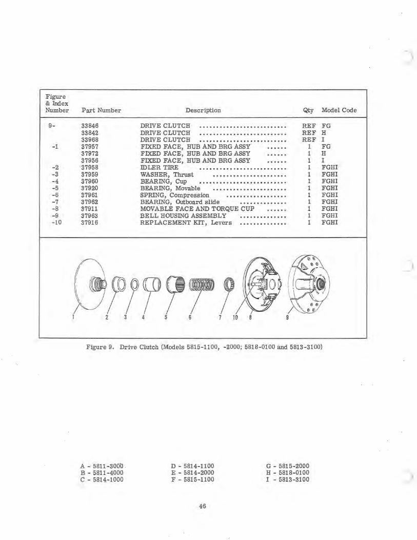
Figure & Index Number
9-
-1
-2 -3 -4 -5 -6 -7 -8 - 9 - 10
Part Number Description Qty Model Code
33846 DRIVE CLUTCH · ......................... REF FG 33842 DRIVE CLUTCH · ......................... REF H 33968 DRIVE CLUTCH · ......................... REF I 37957 FIXED FACE, HUB AND BRG ASSY 1 FG 37972 FIXED FACE, HUB AND BRG ASSY 1 H 37956 FIXED FACE, HUB AND BRG ASSY 1 I 37958 IDLER TIRE · ................... ...... 1 FGHI 37959 WASHER, Thrust ...................... 1 FGHI 37960 BEARING, Cup · ......................... 1 FGHI 37920 BEARING, Movable ...................... 1 FGHI 37961 SPRING, Compression .................. 1 FGHI 37962 BEARING, Outboard slide · ............. 1 FGHI 37911 MOVABLE FACE AND TORQUE CUP 1 FGHI 37963 BELL HOUSING ASSEMBLY · ............. 1 FGHI 37916 REPLACEMENT KIT, Levers · ............. 1 FGHI
f
l "~~ ? 2 3 4 5 6 7 10 8
Figure 9. Drive Clutch (Models 5815-1100, -2000; 5818-0100 and 5813 - 3100)
A - 5811 - 3000 B - 5811-4000 C - 5814- 1000
D - 5814-1100 E - 5814-2000 F - 5815 - 1100
46
G - 5815-2000 H - 5818- 0100 I - 5813-3100
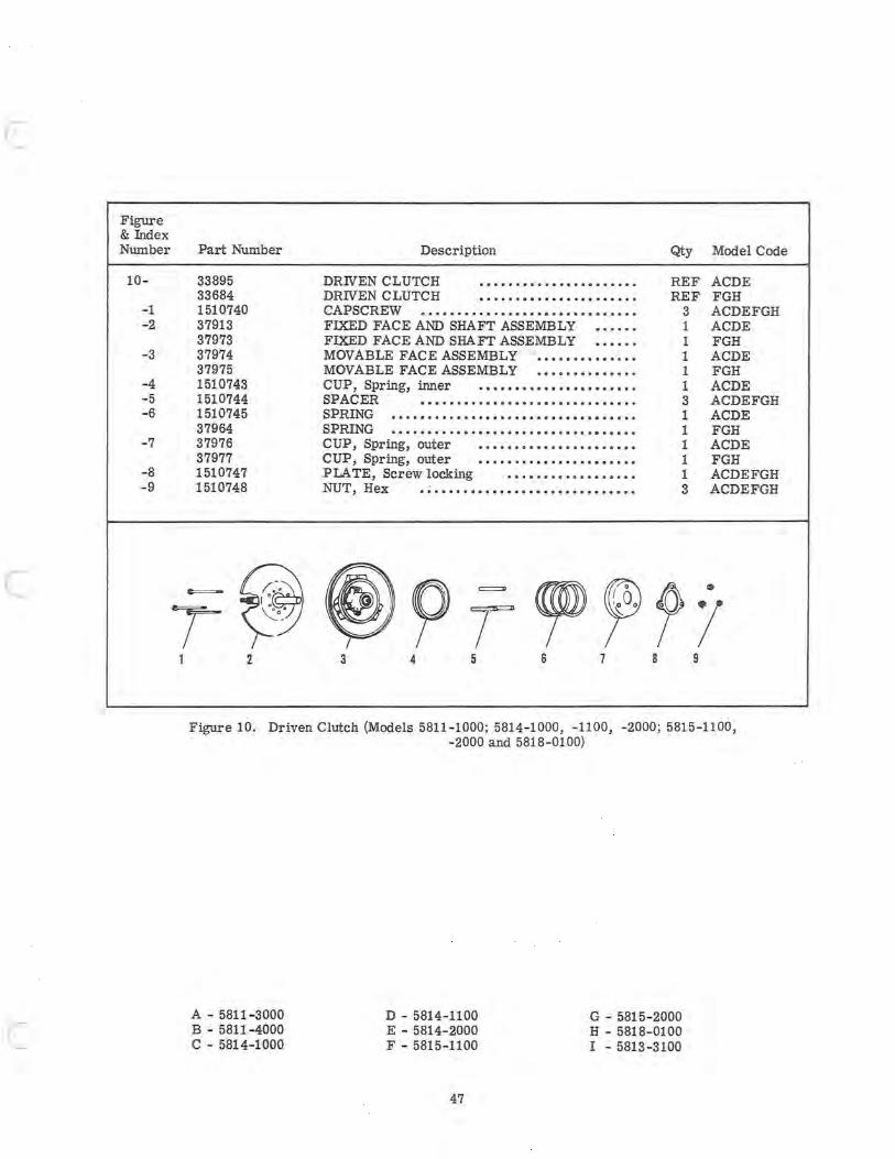
c Figure & Index Number
10-
-1 -2
-3
-4 -5 -6
-7
-8 -9
c
c
Part Number Description Qty Model Code
33895 DRNEN CLUTCH · ..................... REF ACDE 33684 DRNEN CLUTCH · ..................... REF FGH 1510740 CAPSCREW · ............................. 3 ACDEFGH 37913 FIXED FACE AND SHAFT ASSEMBLY ...... 1 ACDE 37973 FIXED FACE AND SHAFT ASSEMBLY ...... 1 FGH 37974 MOVABLE FACE ASSEMBLY .............. 1 ACDE 37975 MOVABLE FACE ASSEMBLY .............. 1 FGH 1510743 CUP, Spring, inner · ..................... 1 ACDE 1510744 SPACER · ............................. 3 ACDEFGH 1510745 SPRING .................................. 1 ACDE 37964 SPRING .................................. 1 FGH 37976 CUP, Spring, outer · ..................... 1 ACDE 37977 CUP, Spring, outer · ..................... 1 FGH 1510747 PLATE, Screw locking .................. 1 ACDEFGH 1510748 NUT, Hex · ............................. 3 ACDEFGH
2 3 4 5 6 7 8 9
Figure 10. Driven Clutch (Models 5811-1000; 5814- 1000, -1100, -2000; 5815-1100, - 2000 and 5818-0100)
A - 5811-3000 B - 5811-4000 C - 5814-1000
D - 5814-1100 E - 5814-2000 F - 5815-1100
47
G - 5815-2000 H - 5818-0100 I - 5813-3100
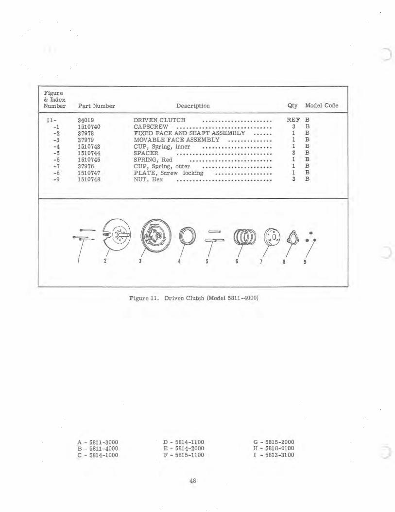
Figure & Index Number
11--1 -2 -3 -4 -5 -6 -7 -8 -9
Part Number Description Qty
34019 DRIVEN CLUTCH · ..................... REF 1510740 CAPSCREW · .... ......................... 3 37978 FIXED FACE AND SHAFT ASSEMBLY ...... 1 37979 MOVABLE FACE ASSEMBLY .............. 1 1510743 CUP, Spring, inner · ..................... 1 1510744 SPACER · ............................. 3 1510745 SPRING, Red .......................... 1 37976 CUP, Spring, outer · ..................... 1 1510747 PLATE, Screw locking .................. 1 1510748 NUT, Hex · ............................. 3
C===-
~ ~ p =
~ ~ fJ> T \:...0_'
T ,~Oo
1 2 3 4 5 6 7 8
Figure 11. Driven Clutch (Model 5811-4000)
A - 5811-3000 B - 5811-4000 C - 5814-1000
D - 5814-1100 E - 5814-2000 F - 5815-1100
48
G - 5815-2000 H - 5818- 0100 I - 5813 -31 00
)
Model Code
B B B B B B B B B B
..
/ 9
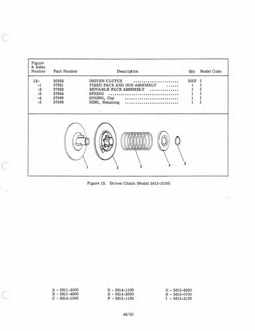
c
c
c
Figure & Index Number
12--1 -2 -3 -4 - 5
Part Number
30392 37921 37922 37964 37965 37966
A - 5811 - 3000 B - 5811 -4000 C - 5814-1000
Description
DRIVEN CLUTCH •••••••••••••••••••••• FIXED FACE AND HUB ASSEMBLY MOVABLE FACE ASSEMBLY •••••••••••••• SPRING ••••••••••••••.••••••••••••••••••• SPRING, Cup •••••••••••••••••••••••••• RING, Retaining ••••••••••••••••••••••••••
2 3 4
Figure 12. Driven Clutch (Model 5813-3100)
Qty
REF 1 1 1 1 1
5
D - 5814-1100 E - 5814-2000 F - 5815-1100
G - 5815-2000 H - 5818-0100 I - 5813-3100
49/50
Model Code
I I I I I I

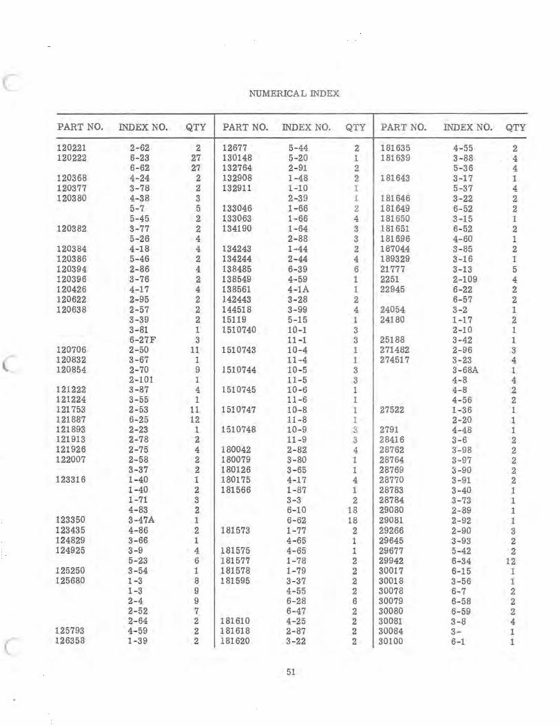
NUMERICAL INDEX
PART NO. INDEX NO. QTY PART NO. INDEX NO. QTY PART NO. INDEX NO. QTY
120221 2- 62 2 12677 5-44 2 181635 4-55 2 120222 6-23 27 130148 5-20 1 181639 3-88 4
6-62 27 132764 2- 91 2 5-36 4 120368 4-24 2 132908 1-48 2 181643 3-17 1 120377 3- 78 2 132911 1-10 1 5-37 4 120380 4- 38 3 2-39 1 181646 3-22 2
5-7 5 133046 1-66 2 181649 6- 52 2 5-45 2 133063 1- 66 4 181650 3-15 1
120382 3- 77 2 134190 1- 64 3 181651 6- 52 2 5-26 4 2- 88 3 181696 4-60 1
120384 4-18 4 134243 1-44 2 187044 3- 85 2 120386 5-46 2 134244 2-44 4 189329 3-16 1 120394 2- 86 4 138485 6-39 6 21777 3-13 5 120396 3-76 2 138549 4- 59 1 2251 2-109 4 120426 4-17 4 138561 4-1A 1 22945 6-22 2 120622 2-95 2 142443 3-28 2 6-57 2 120638 2- 57 2 144518 3-99 4 24054 3-2 1
3-39 2 15119 5-15 1 24180 1-17 2 3-81 1 1510740 10-1 3 2-10 1 6-27F 3 11 -1 3 25188 3-42 1
120706 2- 50 11 1510743 10-4 1 271482 2-96 3 120832 3- 67 1 11-4 1 274517 3-23 4 120854 2-70 9 1510744 10-5 3 3-68A 1
2-101 1 11 - 5 3 4- 8 4 121222 3-87 4 1510745 10- 6 1 4- 8 2 121224 3- 55 1 11-6 1 4- 56 2 121753 2- 53 11 1510747 10-8 1 27522 1-36 1 121887 6-25 12 11-8 1 2-20 1 121893 2-23 1 1510748 10-9 3 2791 4-48 1 121913 2-78 2 11 -9 3 2841 6 3-6 2 121926 2-75 4 180042 2- 82 4 28762 3-98 2 122007 2- 58 2 180079 3- 80 1 28764 3-97 2
3-37 2 180126 3- 65 1 28769 3- 90 2 123316 1-40 1 180175 4-17 4 28770 3-91 2
1-40 2 181566 1- 87 1 28783 3-40 1 1-71 3 3-3 2 28784 3-73 1 4- 83 2 6-10 18 29080 2-89 1
123350 3-47A 1 6-62 18 29081 2-92 1 123435 4- 86 2 181573 1- 77 2 29266 2-90 3 124829 3- 66 1 4-65 1 29645 3-93 2 124925 3-9 4 181575 4- 65 1 29677 5-42 2
5- 23 6 181577 1- 78 2 29942 6-34 12 125250 3- 54 1 181578 1-79 2 30017 6-15 1 125680 1-3 8 181595 3-37 2 30018 3-56 1
1-3 9 4- 55 2 30078 6-7 2 2-4 9 6-28 6 30079 6- 58 2 2-52 7 6-47 2 30080 6-59 2 2- 64 2 181610 4-25 2 30081 3-8 4
125793 4- 59 2 181618 2- 87 2 30084 3- 1 126358 1-39 2 181620 3-22 2 30100 6-1 1
51
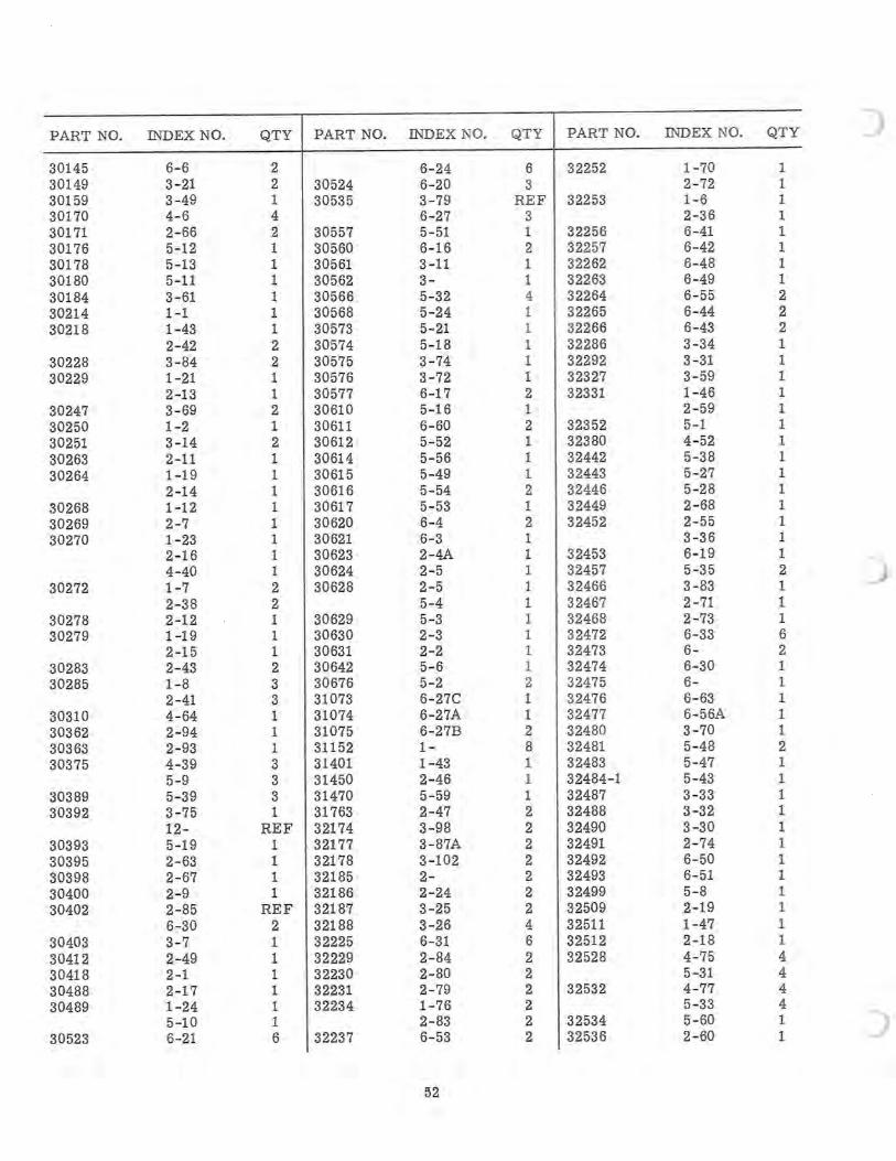
PART NO. INDEX NO. QTY PART NO. INDEX NO. QTY PART NO. INDEX NO. QTY ) 30145 6- 6 2 6-24 6 32252 1-70 1 30149 3-21 2 30524 6-20 3 2-72 1 30159 3-49 1 30535 3-79 RE F 32253 1-6 1 30170 4- 6 4 6-27 3 2-36 1 30171 2-66 2 30557 5-51 1 32256 6-41 1 30176 5-12 1 30560 6-16 2 32257 6-42 1 30178 5-13 1 30561 3-11 1 32262 6-48 1 30180 5-11 1 30562 3- 1 32263 6-49 1 30184 3-61 1 30566 5-32 4 32264 6- 55 2 30214 1-1 1 30568 5-24 1 32265 6-44 2 30218 1-43 1 30573 5-21 1 32266 6-43 2
2-42 2 30574 5-18 1 32286 3-34 1 30228 3- 84 2 30575 3-74 1 32292 3-31 1 30229 1-21 1 30576 3- 72 1 32327 3-59 1
2-13 1 30577 6-17 2 32331 1-46 1 30247 3- 69 2 30610 5-16 1 2-59 1 30250 1-2 1 30611 6- 60 2 32352 5-1 1 30251 3-14 2 30612 5-52 1 32380 4- 52 1 30263 2-11 1 30614 5-56 1 32442 5-38 1 30264 1-19 1 30615 5-49 1 32443 5-27 1
2-14 1 30616 5-54 2 32446 5-28 1 30268 1-12 1 30617 5- 53 1 32449 2-68 1 30269 2-7 1 30620 6-4 2 32452 2-55 1 30270 1- 23 1 30621 6-3 1 3-36 1
2-16 1 30623 2-4A 1 32453 6-19 1 4-40 1 30624 2-5 1 32457 5-35 2
30272 1- 7 2 30628 2-5 1 32466 3- 83 1 2-38 2 5-4 1 32467 2- 71 1
30278 2-12 1 30629 5-3 1 32468 2-73 1 30279 1-19 1 30630 2-3 1 32472 6-33 6
2-15 1 30631 2-2 1 32473 6- 2 30283 2-43 2 30642 5- 6 1 32474 6-30 1 30285 1- 8 3 30676 5-2 2 32475 6- 1
2-41 3 31073 6- 27C 1 32476 6- 63 1 30310 4- 64 1 31074 6-27A 1 32477 6-56A 1 30362 2-94 1 31075 6-27B 2 32480 3-70 1 30363 2- 93 1 31152 1- 8 32481 5-48 2 30375 4-39 3 31401 1-43 1 32483 5-47 1
5-9 3 31450 2-46 1 32484-1 5-43 1 30389 5-39 3 31470 5- 59 1 32487 3-33 1 30392 3- 75 1 31763 2-47 2 32488 3-32 1
12- REF 32174 3-98 2 32490 3-30 1 30393 5-19 1 32177 3-87A 2 32491 2-74 1 30395 2- 63 1 32178 3-102 2 32492 6-50 1 30398 2-67 1 32185 2- 2 32493 6-51 1 30400 2-9 1 32186 2-24 2 32499 5-8 1 30402 2-85 REF 32187 3-25 2 32509 2-19 1
6-30 2 32188 3-26 4 32511 1-47 1 30403 3- 7 1 32225 6-31 6 32512 2-18 1 30412 2-49 1 32229 2-84 2 32528 4-75 4 30418 2-1 1 32230 2-80 2 5-31 4 30488 2-17 1 32231 2-79 2 32532 4- 77 4 30489 1-24 1 32234 1- 76 2 5-33 4
5-10 1 2-83 2 32534 5-60 1 30523 6-21 6 32237 6-53 2 32536 2-60 1
~2
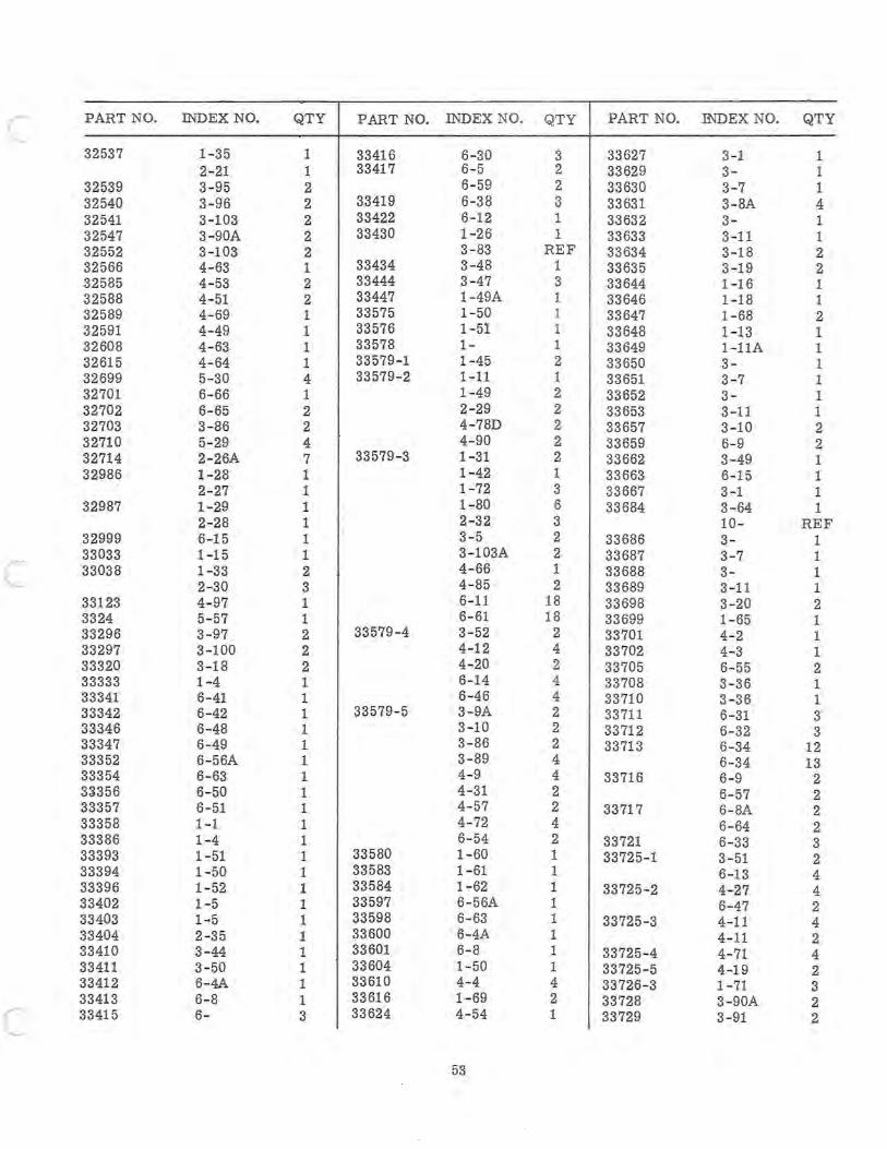
c
c
c
PART NO.
32537
32539 32540 32541 32547 32552 32566 32585 32588 32589 32591 32608 32615 32699 32701 32702 32703 32710 32714 32986
32987
32999 33033 33038
33123 3324 33296 33297 33320 33333 33341 33342 33346 33347 33352 33354 33356 33357 33358 33386 33393 33394 3 3396 33402 33403 3 3 3 3 3 3
3404 3410 3411 3412 3413 3415
INDEX NO.
1-35 2- 21 3-95 3-96 3-103 3-90A 3-103 4- 63 4- 53 4- 51 4- 69 4-49 4- 63 4- 64 5-30 6- 66 6- 65 3- 86 5-29 2-26A 1-28 2- 27 1-29 2-28 6-15 1-15 1-33 2-30 4-97 5- 57 3-97 3-100 3-18 1-4 6- 41 6-42 6-48 6-49 6- 56A 6- 63 6- 50 6- 51 1-1 1-4 1- 51 1- 50 1- 52 1- 5 1 ~ 5
2-35 3-44 3- 50 6-4A 6- 8 6-
QTY PART NO. INDEX NO.
1 33416 6-30 1 33417 6-5 2 6-59 2 33419 6-38 2 33422 6-12 2 33430 1-26 2 3- 83 1 33434 3-48 2 33444 3-47 2 33447 1-49A 1 33575 1- 50 1 33576 1- 51 1 33578 I-1 33579-1 1-45 4 33579- 2 1- 11 1 1-49 2 2-29 2 4-78D 4 4- 90 7 33579-3 1-31 1 1-42 1 1-72 1 1- 80 1 2-32 1 3- 5 1 3-103A 2 4- 66 3 4- 85 1 6-11 1 6- 61 2 33579 -4 3- 52 2 4-12 2 4-20 1 6-14 1 6-46 1 33579- 5 3- 9A 1 3-10 1 3-86 1 3-89 1 4-9 1 4-31 1 4- 57 1 4-72 1 6-54 1 33580 1- 60 1 33583 1- 61 1 33584 1-62 1 33597 6- 56A 1 33598 6-63 1 33600 6-4A 1 33601 6-8 1 33604 1- 50 1 33610 4-4 1 33616 1- 69 3 33624 4- 54
53
QTY PART NO. INDEX NO. QTY
3 33627 3-1 1 2 33629 3- 1 2 33630 3- 7 1 3 33631 3-8A 4 1 33632 3- 1 1 33633 3-11 1
REF 33634 3-18 2 1 33635 3-19 2 3 33644 1-16 1 1 33646 1-18 1 1 33647 1-68 2 1 33648 1-13 1 I 33649 l-11A 1 2 33650 3- 1 1 33651 3-7 1 2 33652 3- 1 2 33653 3-11 1 2 33657 3-10 2 2 33659 6- 9 2 2 33662 3-49 1 1 33663 6-15 1 3 33667 3-1 1 6 33684 3- 64 1 3 10- REF 2 33686 3- 1 2 33687 3- 7 1 1 33688 3- 1 2 33689 3-11 1
18 33698 3-20 2 18 33699 1- 65 1
2 33701 4- 2 1 4 33702 4-3 1 2 33705 6- 55 2 4 33708 3-36 1 4 33710 3-36 1 2 33711 6-31 3 2 33712 6-32 3 2 33 71 3 6-34 12 4 6-34 13 4 33716 6- 9 2 2 6- 57 2 2 33717 6- 8A 2 4 6- 64 2 2 33721 6-33 3 1 33725-1 3- 51 2 1 6-13 4 1 33725-2 4-27 4 1 6-47 2 1 33725-3 4-11 4 1 4- 11 2 1 33725-4 4- 71 4 1 33725- 5 4-19 2 4 33726-3 1-71 3 2 33728 3-90A 2 1 33729 3-91 2
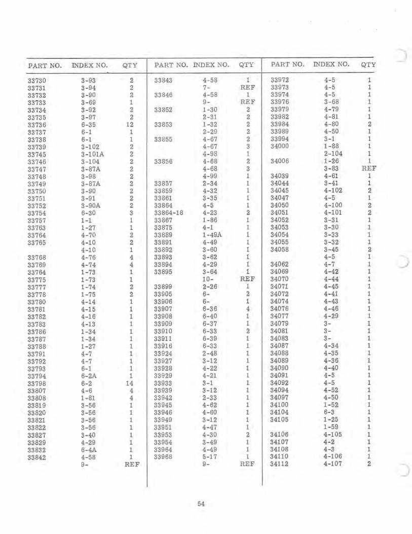
PART NO. INDEX NO. QTY PART NO. INDEX NO. QTY PART NO. INDEX NO. QT Y )
33730 3-93 2 33843 4-58 1 33972 4- 5 1 33731 3-94 2 7- REF 33973 4- 5 1 33732 3-90 2 33846 4-58 1 33974 4- 5 1 33733 3- 69 1 9- REF 33976 3-68 1 33734 3-92 2 33852 1-30 2 33979 4- 79 1 33735 3-97 2 2-31 2 33982 4-81 1 33736 6- 35 12 33853 1-32 2 33984 4-80 2 33737 6-1 1 2-29 2 33989 4-50 1 33738 6-1 1 33855 4-67 2 33994 3-1 1 33739 3-102 2 4-67 3 34000 1-88 1 33745 3-101A 2 4-98 1 2-104 1 33746 3-104 2 33856 4-68 2 34006 1-26 1 33747 3-87A 2 4-68 3 3- 83 RE F 33748 3-98 2 4-99 1 34039 4-61 1 33749 3-87A 2 33857 2-34 1 34044 3- 41 1 33750 3-90 2 33859 4-32 1 34045 4-102 2 33751 3-91 2 33861 3-35 1 34047 4-5 1 33752 3-90A 2 33864 4-5 1 34050 4-100 2 33754 6-30 3 33864-18 4-23 2 34051 4-101 2 33757 1-1 1 33867 1-86 1 34052 3-31 1 33763 1-27 1 33875 4-1 1 34053 3-30 1 33764 4-70 2 33889 1-49A 1 34054 3- 33 1 33765 4-10 2 33891 4-49 1 34055 3-32 1
4-10 1 33892 3-60 1 34058 3-45 2 33768 4-76 4 33893 3-62 1 4- 5 1 33769 4-74 4 33894 4-29 1 34062 4- 7 1 ) 33764 1-73 1 33895 3-64 1 34069 4-42 1 33775 1-73 1 10- REF 34070 4-44 1 33777 1-74 2 33899 2-26 1 34071 4- 45 1 33778 1-75 2 33905 6- 2 34072 4-41 1 33780 4-14 1 33906 6- 1 34074 4- 43 1 33781 4-15 1 33907 6-36 4 34076 4-46 1 33782 4-16 1 33908 6-40 1 34077 4-29 1 33783 4-13 1 33909 6-37 1 34079 3- 1 33786 1-34 1 33910 6-33 2 34081 3- 1 33787 1-34 1 33911 6-39 1 34083 3- 1 33788 1-27 1 33916 6-33 1 34087 4-34 1 33791 4-7 1 33924 2-48 1 34088 4-35 1 33792 4-7 1 33927 3-12 1 34089 4-36 1 33793 6-1 1 33928 4-22 1 34090 4-40 1 33794 6-2A 1 33929 4-21 1 34091 4-5 1 33798 6-2 14 33933 3-1 1 34092 4-5 1 33807 4-6 4 33939 3-12 1 34094 4- 52 1 33808 1-81 4 33942 2-33 1 34097 4-50 1 33819 3-56 1 33945 4-62 1 34100 1-52 1 33820 3-56 1 33946 4-60 1 34104 6- 3 1 33821 3-56 1 33949 3-12 1 34105 1-25 1 33822 3-56 1 33951 4-47 1 1-59 1 33827 3-40 1 33953 4-30 2 34106 4-105 1 33829 4-29 1 33954 3-49 1 34107 4-2 1 33832 6-4A 1 33964 4-49 1 34108 4-3 1 33842 4-58 1 33968 5-17 1 34110 4-106 1
9- REF 9- REF 34112 4-107 2 )
54
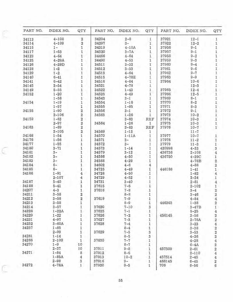
PART NO. INDEX NO. QTY PART NO. INDEX NO. QTY PART NO. INDEX NO. QTY
34113 4-108 2 34294 2-8 1 37921 12-1 1 34114 4-109 2 34297 3- 1 37922 12-2 1 34115 I- I 34319 4-10A 1 37956 9-1 1 34117 1-53 1 34320 3- 7A 1 37957 9-1 1 34123 4- 64 1 34466 4-64 1 37958 9-2 1 34125 4- 29A 1 34490 4-53 1 37959 9-3 1 34126 4-29D 1 34511 3-32 1 37960 9-4 1 34128 1 ~2 1 34512 3-33 1 37961 9- 6 1 34129 1-2 1 34513 4-64 1 37962 9-7 1 34140 6-41 1 34515 4-78E 1 37963 9-9 1 34141 6-42 1 34516 4-64 1 37964 10- 6 1 34145 2-54 1 34521 4-78 1 12-3 1 34149 5-55 1 34522 1- 43 1 37965 12-4 1 34152 1-20 1 34525 4-49 1 37966 12-5 1
1- 58 1 34543 3-1 1 37969 8-1 1 34154 1-19 1 34554 1-16 1 37970 8-2 1
1- 57 1 34555 1-85 1 37971 8-3 1 34155 1-90 2 34556 3-1 1 37972 9-1 1
2-106 2 34563 1-26 1 37973 10-2 1 34159 1- 83 2 3- 83 REF 37974 10-3 1
2-97 2 34564 1-26 1 37975 10 -3 1 34163 1- 89 2 3-83 REF 37976 10-7 1
2-105 2 34569 1-13 1 11 - 7 34168 1-54 1 34570 l-11A 1 37977 10-7 1 34176 1-56 1 34571 3- 1 37978 11 -2 1 34177 1- 55 1 34572 3- 1 37979 11-3 1
c 34180 3-71 1 34573 1-14 1 420998 4-33 3 34181 3- 1 34579 3-12 1 436736 2-108 4 34182 3- 1 34586 4-50 1 436750 4-29C 1 34183 3- 1 34588 4-29 1 4- 78B 2 34184 6- 1 34602 4-6 4 4- 88 2 34185 6- 1 34725 4-49 1 446188 1-41 1 34186 1-91 4 34728 4- 50 1 1- 82 4
2-107 4 34729 4-52 1 2- 24 1 34187 5-40 1 34731 3-40 1 2-81 4 34188 5- 41 1 37615 7-6 1 2-102 1 34207 4- 3 1 37618 7-8 1 3-4 2 34211 3-58 2 8- 8 1 3-46 2 34212 3-58 2 37619 7-9 1 4- 84 4 34213 3-58 1 8-9 1 446363 1-38 2 34214 3-57 1 37620 7-10 3 3-47B 1 34228 1- 22A 1 37625 7-1 1 5-25 4 34229 1-22 1 37626 7-2 1 456145 2- 56 2 34231 4-97 1 37627 7-3 1 2- 78A 2 34232 3- 60A 1 37628 7-4 1 3-23 4 34237 1- 85 1 8-4 1 3-38 2
2-99 1 37629 7-5 3 3-53 2 34261 1-14 1 8- 5 3 4-26 2 34268 2-100 1 37630 7-7 1 4- 28 4 34270 1-9 10 8-7 1 6-4A 2
2-37 10 37911 9-8 1 457509 2- 61 2 34271 1-84 8 37912 8-6 1 2-110 4
1-85A 4 37913 10-2 1 457514 2-45 4 2-98 3 37916 9- 1 466145 6-45 2
c 34272 4- 78A 1 37920 9- 5 1 706 6- 56 6
55
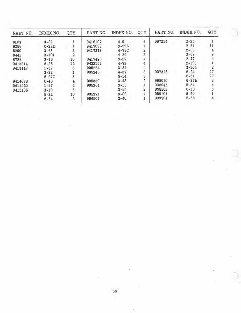
PART NO. INDEX NO. QTY PART NO. INDEX NO. QTY PART NO. INDEX NO. QTY
8103 3- 82 1 9416107 4-9 4 997314 2-25 1 8288 6-27D 1 9417098 3-59A 1 2-51 11 8290 3- 63 2 9417373 4-78C 2 2- 65 4 8441 3-101 2 4-89 2 2- 69 9 8728 2- 76 10 9417420 3-27 4 2- 77 4 9413314 6-26 12 9422157 4- 73 4 2-103 1 9413447 1-37 3 995224 3- 89 4 3-104 2
2-22 1 995246 4-37 3 997316 6-24 27 6-27G 3 5-14 3 6-61 27
9414078 6-46 4 995339 3-43 2 998010 6-27E 3 9414920 1- 67 4 995364 3-15 1 998045 5-34 4 9415106 3-10 3 3- 85 2 998503 6-18 3
5-22 10 995371 3-88 4 999101 5-50 1 6-54 2 996907 2- 40 1 999701 5- 58 4
56