Embed Size (px)
Citation preview


Partner of your Dreams

Welcome to Tankoa Yachts ShipyardWhatever your dream is, Tankoa Yachts will be your best partner
Tankoa Yachts is a tangible fact born from the huge passion for the sea and the
fascination towards the great enterprises of its founders. The shipyard was created
“thinking big”, purposely to build mega yachts and to give them an appropriate assistance
after the sale. The mission of Tankoa is to be the partner of the yacht’s Owner in the
realization of his Dream, make route towards new destinations, excel in technology and
elegance and, last but not least, set free our unique identity and way of living on the sea.
The shipyard is placed in Genoa Sestri Ponente, in the heart of a beautiful country with
a millennial history and tradition in navigation and ships building. The location gives
the shipyard the added value of being in a strategic position in the Mediterranean sea.

Beauty with temperament

Her line is stylish, awesome and graceful at the same time
You decide her temperament
Choose between the relaxing cruise classic semi-displacement version or the powerful
fast version. The model S501 is the ultimate concept of a 50 meters length yacht:
perfect habitability, best luxury comfort and high performance within the 500 gross
tonnage, in order to assure you the great advantage of an easy management. Qualities
that make Tankoa S501 the partner of dreams.
Main deck | Wide saloon with sunbeds

Sun deck | Huge lounge area with sofas, bar and Jacuzzi

Main deck | Foldable balcony
Beach clubGym + Hammam
Main deckWide saloon with sunbeds
Foldable balconies
Upper deckLounge + al fresco dining
Lower deckn° 3 Vip cabins
n° 1 Guest cabin
Main deckn° 1 Owner’s Cabin with balconies
n° 1 Master Cabin
Bow loungeSunbeds + seats 50m
499Gross Tons
Hull and superstructure
entirely built in light alloy 5083
Sun deck 80 mqHuge lounge area with sofas
and bar + Jacuzzi + sunbeds
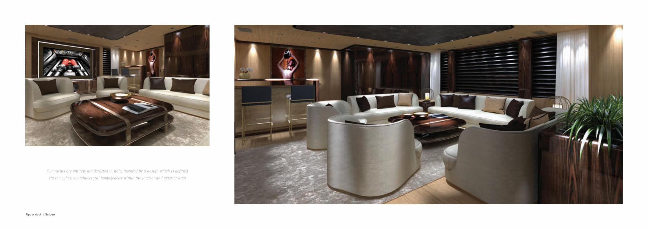
Upper deck | Saloon
Our yachts are entirely handcrafted in Italy, inspired by a design which is defined
via the cohesive architectural homogeneity within the interior and exterior area

Main deck | Saloon
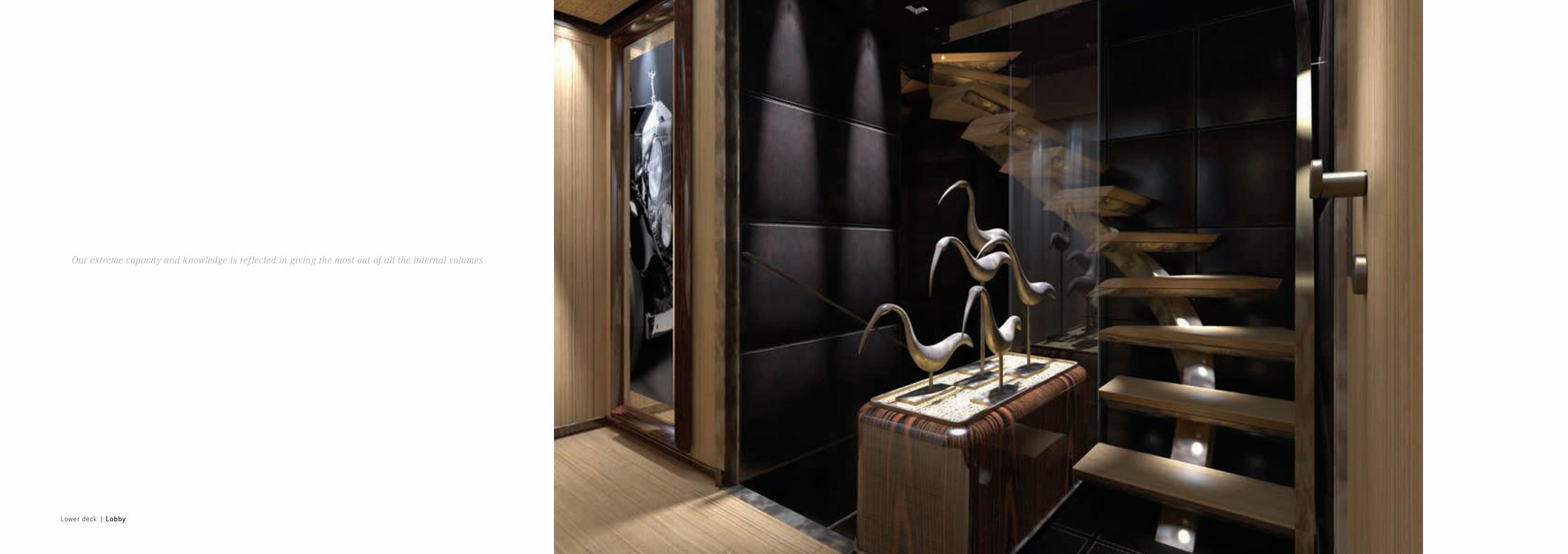
Lower deck | Lobby
Our extreme capacity and knowledge is reflected in giving the most out of all the internal volumes

Main deck | Owner cabin with balcony and bathroom
Thanks to Tankoa’s solid experience, the pursuit of lightness doesn’t compromise
the arrangement of all the best amenities the Owner could wish

Lower deck | Vip cabin with bathroom Main deck | Master cabin

Model S501
Lenght overall 49,99 mt (164 ft)
Beam 9,40 mt (30,80 ft)
Draft full loaded 2,40 mt (7,90 ft)
GRT < 500 GT
Displacement Max 380 tons
Classification Lloyds + MCA
Engines MTU - 2 x 1.432 kW at 2.450 rpm
Propulsion Twin shaft propellers (5 blades)
Generators 2 x 125 kW
Bow thruster 100 kW
Stabilizer + Zero Speed Vosper Naiad
Fuel Capacity approx. 65.000 lt
Max Speed at half load 18 Knots
Cruise Speed 14 Knots
Range at 11 Knots 4.500 n.m.
Hull and superstructure in light alloy 5083
Model S501 Veloce
Lenght overall 49,99 mt (164 ft)
Beam 9,40 mt (30,80 ft)
Draft full loaded 2,30 mt (7,22 ft)
GRT < 500 GT
Displacement Max 300 tons
Classification Lloyds + MCA
Engines 2 x 2.720 kW at 2.100 rpm
Propulsion Twin shaft propellers (5 blades)
Generators 2 x 125 kW + Emergency Generator
Bow thruster 100 kW
Stabilizer + Zero Speed Vosper Naiad
Fuel Capacity approx. 45.000 lt
Max Speed at half load 27 Knots
Cruise Speed 22 Knots
Range at 14 Knots 2.200 n.m.
Hull and superstructure in light alloy 5083

notes
0 01 02 03 04 05 06 07 08 09 10 11 12 13 14 15 16 17 18 19 20 21 22 23 24 25 26 27 28 29 30 31 32 33 34 35 36 37 38 39 40 41 42 43 44 45 46 47 48 49 50 51 52 53 54 55 56 57 58 59 60 61 62 63 6564 66 67 68

f ly deck
0 01 02 03 04 05 06 07 08 09 10 11 12 13 14 15 16 17 18 19 20 21 22 23 24 25 26 27 28 29 30 31 32 33 34 35 36 37 38 39 40 41 42 43 44 45 46 47 48 49 50 51 52 53 54 55 56 57 58 59 60 61 62 63 6564 66 67 68
FridgeIce
Maker
Up - down Up - down
UP
UP
UP
UP
UP
UP
UP
UP&DN
UP&DN
UP
Tepan
TV 42''
escape
Escape
ESCAPE

upper deck
0 01 02 03 04 05 06 07 08 09 10 11 12 13 14 15 16 17 18 19 20 21 22 23 24 25 26 27 28 29 30 31 32 33 34 35 36 37 38 39 40 41 42 43 44 45 46 47 48 49 50 51 52 53 54 55 56 57 58 59 60 61 62 63 6564 66 67 68
DAYHEAD
SKYLOUNGE
WHEELHOUSE
UP
TV 75"
TV32''
PANTRYQ.E.
Q.E.
CAPTAIN CABINAC
AC
FridgeIcemaker
TECH.SPACE
TECH.SPACE
TV 6
5''
moquette
moquette
UP
UP
OUT
UP
UP
UP
Fridge
UP
UP&DN
UP&DN
escape
Escape
ESCAPE
Lift

main deck
0 01 02 03 04 05 06 07 08 09 10 11 12 13 14 15 16 17 18 19 20 21 22 23 24 25 26 27 28 29 30 31 32 33 34 35 36 37 38 39 40 41 42 43 44 45 46 47 48 49 50 51 52 53 54 55 56 57 58 59 60 61 62 63 6564 66 67 68
OUT
UP
PANTRY
MAIN SALOON
FridgeDining area
MAIN ENTRANCE
UP
IN IN
DAY
A/C
Escape
TOILETTE
winecooler
UP
VIPBATHROOM
TV55''
MASTERCABIN
TECH.SPACE
LOBBY
OWNERCABINFridge
Icemaker
UP
Fridge
Icemaker
FRIDGECOFFEE
SAFE
OWNERBATHROOM
OWNERDRESSING
STORECROCKERY
FRIDGECOFFEE
StoreStore
SAFE
SHOWERSTEAM
GENERATOR
TV 65"
Shoes
moquette
carpet
carpet
UP
AC ROOM
ESCAPE
stone
stone
TV55''
Store
RAC
Fridge
Store
A/C
A/C
A/C
TECH.SPACE
TECH.SPACE
TECH.SPACE
TECH.SPACE
TECH.SPACE
TECH.SPACE
TECH.SPACE
Store
winecooler
Escape
EmergencyEscape
BreathingDevice
escape
ESCAPE
escapemicrowave
coffeem
achine
dish
was
her
dish
was
her
Lift
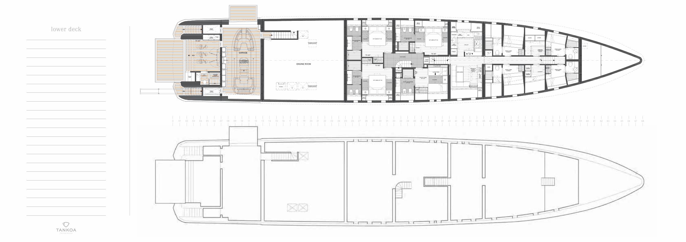
lower deck
0 01 02 03 04 05 06 07 08 09 10 11 12 13 14 15 16 17 18 19 20 21 22 23 24 25 26 27 28 29 30 31 32 33 34 35 36 37 38 39 40 41 42 43 44 45 46 47 48 49 50 51 52 53 54 55 56 57 58 59 60 61 62 63 6564 66 67 68
UP
UP
IN IN
OUT
ENGINE ROOM
TECH.SPACE
Escape
TECH.SPACE
GYM
Fridge
UP
TOILETTEDAY
Divingstore
Divingstore
SHOWERSTEAM
GENERATOR
Coffeemachine
Divingstore
UP
ESCAPE
GARAGE
VIP BATHROOMAFT SX
VIP CABIN AFT DX
VIP CABIN AFT SXVIP CABIN AFT SX
GUEST BATHROOMAFT DX
UP
GUEST CABINAFT DX
VIP BATHROOMAFT SX
CREW MESS
TECH.SPACE
TV 40''
TV 40''
TECH.SPACE
TECH.SPACE
VIP BATHROOMAFT DX
LINEN
TV37''
TV 32''
UP
TECH.SPACE
STORAGE
PULLMAN BED
SLIDING BED
CO
FFEE
MA
CH
INE
SAFE
SA
FE
SAFE SAFE HI-FI
TV 40''
TECH.SPACE
TECH.SPACE
TEC
H.
SP
AC
E
FRIDGE
moquette moquette
moquettemoquette
hard leather
moquettemoquette
moquette
TECH.SPACE
LAUNDRY
UP
CREW CABINDOUBLE
CREW CABINDOUBLE
CREW CABINDOUBLE
CREW CABINDOUBLE
DOUBLEDRYER
WASHINGMACHIN
WASHINGMACHIN
FREIDGEFREEZER
ROOM
Divingstore
TV 40''
TECH.SPACE
TECH.SPACE
LINEN
Q.E.
STORE STORE
DOUBLEDRYER
escapeescape
Emergency EscapeBreathing Device
Emergency EscapeBreathing Device
Emergency EscapeBreathing Device
EmergencyEscape
BreathingDevice
TECH.SPACE
TECH.SPACE
GALLEY
DISH WASHER
FRIDGE
TECH.SPACE
DISHWASHER
FREEZER
oven
ovenm
icrowave
EatingLight

Main System
1 General
2 Classification and certification
3 Main engines
4 Anchor windlasses
5 Active stabilizers
6 Fire fighting sytem
7 Fire main system
8 Bow thruster
9 Air conditioning and ventilation plant
10 Fixed water spraying system in the accomodation areas
11 Deck planking
12 Fixed system in engine room and machinery area
13 Service areas
14 Reverse/reduction gear, shafts and propellers
15 Electrical power system
16 Bilge system
17 Garage
18 Fuel equipment
1 - General
The vessel described within this Technical Specification is
a luxury displacement Motor Yacht with light alloy hull and
superstructure.
The vessel is designed for deep-sea or open ocean navigation,
without any limitations. Hence, it is designed so to have the
maximum/highest navigation requirements and comforts.
The project development shall comply with the requirements
of the Classification Society.
The Yacht shall be designed and build under the highest
European Standards for luxury Yachts destined to
(commercial) Charter and worldwide navigation without
limitations. Hence, the design, the materials, the building
processes and the equipment shall be selected with respect
of such principle.
2 - Classification and certification
The construction of this Yacht, as well as the installation
of her machinery, shall be carried out under the survey
and in accordance with all the relevant Rules, in force
at the time of construction, of the following Societies:
Lloyd Register of Shipping (LRS),
for the issue of the Class Certificate: 100 A1, SSC, YACHT,
MONO, G6, [ ] LMC;
MCA
Letter of Compliance for the safety of large commercial/
charter Yachts, without any limitations to the navigation,
issued by the designated Classification Society.
3 - Main engines
N° 2 Sea Diesel Engines Mtu
Mod. 8V4000m54r Application group 1A, unrestricted.
Engines built according to the “Marine Propulsion” MTU
product line. Turbocharged and inter-refrigerated engines
Turbocharged air cooling system, fresh water cooled Engine
Jacket cooling system, fresh water cooled electronically
controlled fuel injection system electronically controlled
engine monitoring, control and management system
electric starter water-cooling system with built-in plate heat
exchanger cooling water from ships’ sea intakes plant.
Technical characteristics:
Diesel Cycle: 4 strokes
Air suction: turbocharged
Injection: direct
N° of cylinders: 8 “V”
Bore: 170 mm
Stroke: 210 mm
Compression ratio: 14 : 1
Cylinder Displacement: 4,77 lt.
Total Displacement: 38,2 lt.
Dry engine weight, Net dry: 5.460 kg
The engines shall be compliant with the IMO exhaust
emission regulation TIER III.
- Rating for the “Unrestricted” service: bkW
- Speed of the nominal rotation: 1.600 rpm
4 - Anchor windlasses
N° 2 vertical type anchor windlasses (by OPEM SISTEMI)
will be installed, with stainless steel gypsy and stainless steel
capstan. Windlasses shall be operated by 400 V electric motor
with “soft-starter” device, variable speed and reversible.
Power and speed of the windlasses shall be in accordance
with the Rules (approx. 7,5 kW power and 14 mt/min speed).
The anchor chains shall be made of hot galvanized high-
resistance steel, U2 stud link, diameter of 17,5 mm.
Length of chains as required by the Classification Society.
From the hawse pipe to the chain gipsy shall be fitted
opposed stainless steel guide rollers and a chain stopper
with bar compressor for tightening anchors, made also
in stainless steel, complete with hand wheel.
Anchors
N°2 hot galvanized anchors, of high holding power
approximately 340 kg, in accordance with the Equipment
Number approved by the Class.
5 - Active stabilizers
In order to ensure comfort and stability on board, non-
retractable Naiad or equivalent stabilizer fins system for ship
under way and at Anchor will be installed and will consist:
n° 2 model 575 Fin actuator assemblies with heat-treated
and passivated stainless steel shaft stock, heavy duty
tapered-roller main bearings. Each assembly will include
precision electro-hydraulic servo valve pre-mounted on a
servo manifold including center lock, crossover relief valves
and emergency fin centering screws.

6 - Fire fighting system
The firefighting system shall include fixed as well as portable
extinguishing equipment, in compliance with the lassification
Societies and MCA regulations. On the main bridge by the
escape exit from the Engine Room, the main firefighting
station shall be fitted with control on: the fixed fire
extinguishing system in the Engine Room, the Generators
shut-off system, the ventilation shut-off system, the fuel
transfer pump and all the other fire prevention procedures
contemplated by the fire prevention plan approved by the
Classification Societies.
A regulations compliant fire alarm system with heat and
smoke sensors shall be fitted in the accommodation and all
technical areas, with a monitoring system on the wheelhouse.
7 - Fire main system
The fire main along the ship will be fed both in normal and
emergency conditions by the above mentioned fire/bilge pumps.
Fire pumps will suck from sea intake (in engine room and
in forward area) and will discharge into the main fire line
feeding the fire hydrants; fire hydrants will be arranged
throughout the vessel in accordance with the requirements
of the Classification Society and Flag Administration.
The fire main will not be permanently pressurized. An
isolation valve will be fitted on the fire main, in a readily
accessible area above main deck or in any case outside the
engine room, to let the fire main be fed by the emergency
fire pump in case of damage in engine room.
All lockers in which hydrants and hoses are stowed will have
clearly identifiable labels attached, to the approval of the
Flag Administration. One international shore connection will
be provided to enable the shore supply to be connected to
the ship’s fire main when in port.
8 - Bow thruster
One transversal propeller Naiad VT100E or CMC DUALIS
BTM100EA or equivalent will be installed at the bow. It will
be fitted into a 650 mm diameter tunnel, electrically driven,
frequency controlled, 100 kW, thrust of at least 1.000 kg.
9 - Air conditioning and ventilation plant
The mixed type air conditioning system shall comprise a fan coil
system (circulating chilled water) and a treated air induction
plant (chilled/heated with humidity control) with adequate
extraction. In Summer time, the water circulating in the
fan-coils shall be chilled by the cooling units with refrigerant
cycle (semi hermetic compressors) to a temperature about
6°-10°C. In Winter time, through the reversal of the Freon
flow, the circulating water shall be heated to a temperature
about 44°-50°C. Each room temperature shall be individually
controlled by digital thermostats which shall control the water
system solenoid valves and the fan speed. The external
air shall be treated by an AHV (Air Handling Unit) dimensioned
so to provide at least 25 m3/h air circulation per person with
an adequate number of air changes (6 changes per hour).
In order to reduce the noise level, the air ducting shall be
dimensioned so to allow a maximum speed of 6 mt/sec. The
AHV shall also include an adequate humidity control system
for the treated air, before letting it into the ducting.
10 - Fixed water spraying system in the accommodation spaces
A fixed water spraying extinguisher (NOVENCO, ULTRAFOG)
with ceiling sprinklers shall be fitted in every accommodation
area; though centralized, such system shall be divided in
zones, controlled by dedicated detectors, so to be activated
only in the interested area. The monitoring and functioning
control panel shall be fitted in the wheelhouse. The system
has to be in accordance to the Rules and approved by
Classification Society.
11 - Deck planking
As also indicated on the G. A. Plan, all the decks, the
external stairs connecting to various decks and the platform
of the transom door shall be covered in teak, except for the
windlasses area.
All the external decks shall be accurately leveled with
epoxy mastic leveling compound. The teak decks shall have
stringers of 80 mm minimum width fitting perfectly its inner
and outer side, as well as a central king plank.
The planks shall be no less than 60 mm wide and 4 mt long,
except for those areas where the deck geometry does not
allow it, in which case they shall run parallel to the deck
contour. The final thickness of the teak covering on decks,
stairs and the swimming platform of the transom shall
be 15mm. All the deck openings (hatchways and hatches,
windlasses area, bitts/bollards foundations, warping
capstans, scuppers and drains, etc.) on various decks shall
have border coaming of the same width as the stringers.
The selected teak shall be the best quality having uniform
color without any spots, nods or any tar embedding.
12 - Fixed system in engine room and machinery area
A fixed gas extinguisher type CO2 (maker MINIMAX) with
manual release activation shall be fitted with adequate size
bottles (calculated on the gross volume of the space to be
protected) also located within the same space.
The system shall have to be approved by the Classification
Societies.
13 - Service areas
All the service areas such as the crew deck, where kitchens
and crew rooms are located, and the tank deck housing
technical rooms, laundry and refrigerating areas, are up to
the highest standards and respectful of the international
requirements for on-board living.
14 - Reverse/reduction gear, shafts and propellers
The reverse/reduction gear shall be provided with the
engines and connected to them through an elastic couplings
of type and characteristics specified by the gears maker.
These shall be ZF or REINTJES.
Shaft line traditional solution:
Stuffing box’ seals will be of “Deep Sea Seal” ceramic type
with pneumatic chamber or similar. The shaft’s supporting
bushings will be Thordon or rubber or equivalent. Propeller
shafts will be Aquamet 17 or equivalent, coupled to the
reduction gears’ flanges.
Calculations on torsional, axial and lateral vibrations will
be submitted to the Classification Society for approval.
The shaft lines system will have no torsional, axial or side
vibrations and will be aligned in compliance within the
allowance accepted by the manufacturers. The complete shaft
lines system will be built to ensure that there is no critical
speed within the ordinary range of operation of the yacht.
n° 2 x 5 blades propeller with diameter 1.700 mm. (DETRA),
outward rotating Material: NI.BR.AL Propeller finishing: ISO
484 (1981) Class S.

15 - Electrical power system
The electrical system will be fed by two main diesel driven
synchronous generators, capable of running continuously in
parallel operation. The two generators, Kohler, will feed the
400 V, 50 Hz, 3ph+neutral bus-bars of the main switchgear,
on twin bus-bars systems linked by a bus-tie. The estimated
power of each generator is of 125 kW, continuous service,
with rated power factor of 0,8.
The parallel operation of the generators can be performed
both manually and automatically, with automatic active and
reactive load sharing; the manual operation will be done
from the main switchgear, while the automatic operation
is possible both from the main switchgear and from the
wheelhouse. A shore supply with a rated power 100 kW, p.f.
0,8, at 400 V, 50 Hz, 3phase + neutral will be provided; the
shore supply will consist of a solid state electronic converter,
Asea or equivalent supply, capable to be fed at a voltage in
the range from 208 to 415 Vac +/- 10%, 40 to 70 Hz, 3phase,
and with the above said output, acting in this way also as
galvanic insulator from the ashore electrical system; the
output shore supply cables will feed one of the two bus-bars
sections of the main switchgear, via an automatic circuit
breaker.
The emergency service batteries capacity will be as large
as necessary to supply for three hours at least the following
users, as required by the Rules of any Classification Society:
the craft’s emergency lights to assist escape from all
enclosed spaces and to illuminate the disembarkation
position and the craft’s navigation station (with a minimal
time duration extended to eight hours at least).
An indicator is to be mounted on the wheelhouse control
station to indicate when the emergency service batteries
are being discharged. The radio installation (GMDSS and
VHF/DSC) will be fed by a dedicated group of batteries
of proper capacity.
16 - Blige system
The bilge system shall have a remote controlled monitoring
and checking system capable of been operated from the
wheelhouse and from the Engine room. The system shall be
fitted with an alarm system for water leakage in the bilges
and connected to the monitoring system and a number of
24 V CC electro valves to suck from the concerned bilge.
In addition to the main system an emergency pump shall
be fitted. All shall comply to the Classification Societies
requirements.
Fixed system in engine room and machinery area
A fixed gas extinguisher type CO2 (maker MINIMAX) with
manual release activation shall be fitted with adequate size
bottles (calculated on the gross volume of the space to be
protected) also located within the same space. The system
shall have to be approved by the Classification Societies.
17 - Garage
The yacht will be equipped with a garage area capable
of recovery one main tender of max lenght 6,5 mt and
1,5 tons weight.
18 - Fuel equipement
The fuel is kept in double bottom tanks integrated in the
structure of the hull with a total capacity of about 65.000 lt.
In the engine room the Builder will install two Gianneschi or
equivalent fuel transfer centrifugal type self-priming electro
pumps, capacity 6-12 m3/h at 38-7 mt of water column.
Pumps will have bronze body and impeller, stainless steel
AISI 316 shaft. In parallel with the two transfer pumps, an
emergency transfer hand pump will be fitted.
Each fuel transfer main pumps will connect the fuel storage
tanks to its own service tanks, moreover cross connection
between the pumps is provided in order to allow each pump
to feed each tank in case of emergency. Two fuel duplex
filters, one each main engines, mounted on the engine
itself, with diverter valve will be fitted. Moreover, a duplex
Separ independent filter will be fitted on the feeding fuel
line for each main engine and diesel generator.
AIC
ALFA LAVAL
ALTRA LUCE
AP MARINE
ASEA
AUTRONICA
CATERPILLAR
CANTU’ CONTRACT
CP NAUTICA
CRESTRON
DETRA
DVZ SERVICE
FASER
GIANNESCHI
GLENDINNING
HAMANN AG
HEINEN & HOPMAN
HUG
IDROMAR
IL FRIGORIFERO / FRIGIT
INTERSONA
JETS & VACCUM
LIBRA
MATRIX
MINIMAX
MOTOMAR
NEWTHEX
NORTHERN LIGHTS
WILHELNSEN NOVENCO
OPAC MARE
OPEM SISTEMI
PIZZORNO & LINI
POLIPODIO
PRISMA
ROLLS-ROYCE
SCM
TEBUL
VEGA
VIRAVER
VOSPER NAIAD DYNAMICS
Main Suppliers

44°25’15” 008°50’45”
The shipyard is placed in Genoa Sestri Ponente,
near “Cristoforo Colombo” International Airport,
few kilometers away from its exit on the
“Genova-Ventimiglia” (A10 Highway) and opposite
of the New Yachts Marina.
Gra
phic
Des
ign:
Fed
eric
o e
Pie
r Fr
ance
sco
Pazz
i
Sta
mpa
: G
alli
Thie
rry
Tankoa Yachts S.p.A.
P.Iva 03538070107
T + 39 010 8991100
F + 39 010 8991118
Via Cibrario, snc
16154 Genova Sestri Ponente, Italy
www.tankoa.it