Embed Size (px)
Citation preview

PARTICIPATORY SCIENCE EXHIBITS
Vikram A.Sarabhai Community Science Centre
Ahmedabad 380009, Gujarat, India
Foreword
It has always been a great delight to go to the Science Centre and see in its corridors
children of all ages working with the participatory science exhibits on their own. These
exhibits best reflect the spirit of the Science Centre showing these children learning
while having such a nice time. People have often asked why this experiment and its
ideas cannot be made more widely available. There has been a growing demand from a
variety of organizations, schools, teachers, and students interested in science projects
to know more about these participatory exhibits. It is, therefore, a long-felt need that
this book will be fulfilling, and I am sure it will initiate creative thinking amongst all
those who come in contact with these ideas. We would like to thank the Ministry of
Education and Culture for their generous financial support that has made this
publication possible.
Kartikeya V. Sarabhai
31-3-84
INTRODUCTION
Vikram A. Sarabhai Community Science Centre started conducting programmes for
students and teachers during the year 1967-68. Several programmes such as ‘Science
Learning Through Inquiry’, ‘Introductory Physical Science’ ‘Motivated students’
Programmes’ and ‘Teachers’ Programmes’ were tried out. In some of them teaching
aids and simple science toys were developed. By the year 1972-73 we had developed
and displayed exhibitions on themes such a ‘man and space, heart, molecules,
pollution etc.
During the year 1972-73 a project entitled ‘Science Communication Project’ was
undertaken by Dr. Minal Sen. She collected and designed some simple experiments
and installed them in the courtyard of the Centre.
These were called ‘DO-IT-YOURSELF EXPERIMENTS’.

Gradually these do-it-yourself experiments occupied the whole of the Centre’s
courtyard. The exhibits were designed with the following questions in mind.
1. Is the exhibit interesting?
2. Does it involve action?
3. Can it withstand repeated handling by visitors!
4. Is it low cost?
5. Can it be displayed in an attractive way?
The exhibits were not primarily designed to teach some concept in science or
mathematics but to result in interaction with the exhibit leading to fun and joy. The
learning in this case is a pleasurable and voluntary activity. The exhibits may be divided
into the following categories : Puzzles and playthings Interactive Science Exhibits
Science Playground Illusions
Display for observation and study (aquarium, birds, rabbits, tortoise, etc.) Charts on
History of Textiles, History of Mathematics etc.
Several of the exhibits are solitary games in which the aim is spelt out on a small card.
Some of these solitary games involve the assembling of given pieces into a simple
object such as a cube or a given shape while others involve doing a certain task in the
least number of moves.
Apart from simple experiments, toys and puzzles, we have also put up an aquarium
and an aviary in the courtyard for observing birds, fishes, tortoises and other living
organisms.
We have also used items such as periodic table, which was converted to a form in
which each element was represented by a cube which could rotate on its axis. The
various properties of elements were painted on different faces of the cube using a
colour code. We have also made large scale models of molecules such as sodium
chloride, caesium chloride, and DNA. for display.
We have been trying for some time to get support for setting up interactive games
based on mini computers. This area has seen a tremendous growth in the last decade
especially after the advent of the microchip.
This also led to video parlours and hand held single purpose games. Since 1980 the
personal home computer is available cheaply. We are in the process of installing a
minicomputer for use by children. Many versions of the games can be put on cassette
tape or floppy discs for use on home computer. During 1981 several hundred games
were available, many of them with colour and sound effects for personal home
computers. They are now used for instruction, graphics, simulation and problem
solving. Although it may not be possible for an individual or schools or colleges to
avail of this facility individually, a centralised facility can always be shared. Thus the
youth in the country can acquaint themselves with technology which is taking over
rapidly.
The participatory exhibits are very important for schools as they pro- vide a simple
low cost method of generating student interest in science and mathematics and teach
them problem solving.
Designing A Participatory Exhibit
Exhibits in a Science Centre or a Museum are not only to be seen but they have to
fulfil an educational role.
What can be a participatory element in an exhibit? When we talk about a participatory
exhibit each one of us is thinking about it in a different way. The designer thinks from
design point of view, while a curator or educator thinks from the content point of view.
Here are some features of a participatory exhibit :
a. A participatory exhibit is one with which the participant interacts. He or she handles
the exhibit, tries out several times and creates his or her own understanding about it. It
throws light on an idea or a group of ideas.
b. There may be a descriptive label on it or it may have a few questions. There may be
operational charts or symbols.
c. It satisfies certain curiosity and raises further questions.
d. It is open and not a black box.
e. It can be so designed that one can operate it without much complexity.
f. it has to he sturdy so that it can bear wear and tear of visitors’ constant use.
g. As far as possible it should not have highly sophisticated mechanisms. It should be
easy to repair.

The basic elements of a participatory exhibit
Content
The first and foremost element of participatory exhibit is idea or concept. It must have
a clearly detectable idea.
It must have good visual communication elements like colour, symbols.
It should have obvious operation system.
Display of a participatory exhibit
Participatory exhibit have a strong visual and operational appeal and therefore display
will have following characteristics
- Simple and uncluttered
- Reasonably spaced so that people can use the unit well.
- Non-dramatic :
To most of the participants an object is attractive from action point of view and
therefore dramatic display is not needed.
Correlated Display :
If there are several exhibits in a total display they can be grouped in such a way that
they can be conceptually related. For example, an exhibit like parrot and cage, moving
pictures wheel or a flip book.
— Available light display :
It is found that simplicity of lighting gives directness to participatory exhibits.
Area of Display :
As far as possible semi open area is a very workable
proposition. The area can be a chawk or a broad corridor.
When a room is chosen it should be a large enough room
where groups of visitors ca n freely move and can stop over
at the exhibit of their choice. In fair weather certain displays
can be in open areas like gardens. Standardization and variety
in display of participatory exhibits
Many participatory exhibits can have four schematic parts.
A= Display
B = Operating mechanism
C= Stand
D = Caption
Parts A and B will go together. Part C should be detachable
and interchangeable. Caption should also have a short write
up on the exhibit.

How ideas generate in the process of development of Participatory exhibit Design.
There are various ways in which the ideas about science participatory exhibits
generate.
1. From an experiment
2. From an observation of an existing gadget.
3. Improvement on a system used.
4. From an exhibit existing somewhere else.
5. From ‘how to do’ magazines or books.
6. From science project by students.
7. Purely from imagination.
Whatever the source may be, designing of a participatory exhibit, may involve the
following steps.
Idea
Contents
Trial and feedback
Trial model
Final exhibit
Presentation fromPresentation from the human mind and body point of view:
Putting an idea in the form of an interactive exhibit is very different from an equipment
or experiment in the laboratory. The process of design involves two major aspects :
1. Contents
2. Form. After contents are analysed and broad presentation is ready, the exterior form
is designed.
One basic principle of exterior design is ‘FROM INSIDE OUT’
The structure design has to take ca re of the inside system first and then outside
design is planned.
PARROT &
CAGE MOVING
DRUM FLIP BOOK

Here are some questions which will arise in the designer’s mind.
1. Will this attract visitors?
2. Will this be easy in handling?
3. Are human body and mind getting involved with the exhibit?
4. Does it convey the idea or concept?
5. Is it sturdy enough?
6. Has it aesthetic appeal?
7. Would it need trials in fabrication?
8. Are materials local?
9. What are the alternative uses of this exhibit?
10. Is it accessible to children?
DOUBLE CONE
Principle: This exhibit works on the principle that the centre of gravity of a body tends
to move from a higher level to a lower level.
Construction: The exhibit consists of a triangular sloping frame, and a double cone as
shown in the diagram.
Description: To begin with a cylindrical rod is kept at the broader end (which is at a
higher level) of the frame. One sees the rod rolling down. The double cone is kept on
the frame where the rod was kept earlier. The double cone does not roll down. The
double cone is now kept on the other end of the frame (lower end). One can see that it
rolls up unlike the cylindrical rod.
Remarks: Due to the typical shape of the double cone the centre of gravity is at a
higher level when it is kept at the lower end of the frame than when kept at the higher
end. When the double cone rolls up, the centre of gravity comes down, so, in effect,
therefore, the double cone is rolling down. The cylindrical rod, however, moves only
from the higher end of the frame to the lower end of the frame, since the centre of
gravity of the rod is at a higher level when kept at the higher end than at the lower end.
Material required: A wooden triangular sloping frame, a double cone made of uniform
wood cylindrical rod.

STUBBORN MAN
GIANT YO YO
Magnets having ‘similar poles repel each
other. Magnets having opposite poles attract
each other. In ‘Stubborn Man’ -the nose is
cut out and separated. Nose spot is A, and
cut out is B. Now the viewer of the exhibit
has to stick the cut out portion of the nose
on the nose spot A. Both have magnets with
like poles facing each other. This exhibit is
45 cm tall and colourful. 12mm Ply-board is
the material used. Magnets can provide
many ideas for participatory exhibits.
Principle: This simple exhibit works on the principle of inertia
and conversion of potential energy to kinetic and rotational
energy and vice versa. Construction: The giant YO YO
basically consists of a wooden disc of about 15 cm in
diameter. Through the centre passes a rod as shown in the
figure. The disc and the rod should be fitted tightly. At equal
distance on either side of the disc, strings are attached to the
rod as shown in the figure. The disc is hung from the two ends
symmetrically. The disc is twirled to some height and then
released. As it comes down, it moves faster. After reaching its
lowest point it rises again retaining the same sense of rotation.
The process continues for quite sometime. The disc is able to
roll down and up again retaining the same sense of rotation by
itself due to inertia and conversion of potential energy into
kinetic energy and rotational energy and vice versa.
Remarks : One may notice that the disc does not achieve the
same height from where its was released earlier. This is due to
friction and hence the precess eventually stops.
Material required : A wooden disc of diameter 15 cm and
thickness 0·5 cm A rod of length 15 cm string (thick nylon
strings work well), a wooden or metallic frame as shown in the
diagram.

INTERFERENCE OF LIGHT WAVES
Principle : This exhibit is based on interference of waves emanating from two coherent
sources of light. If the waves arrive in phase at a particular point, they interfere
constructively giving rise to a bright band. If they arrive out of phase, they interfere
destructively and a dark band is seen. Here two thin slits parallel and close to each
other serve as two coherent sources of light.
Description : One glass plate is taken and painted with optically opaque solution. With
the help of a razor blade, two thin slits are made close to each other. Another glass
plate is taken and placed over the double slit to protect it. A single filament lamp is now
taken and covered half with a gelatine colour filter. Holding the double slit close to the
eyes, if one looks at the electric lamp through the coloured filter, one can see dark and
bright bands of the same colour as that of the filter at regular intervals. These bands are
called fringes. If one looks at white light through double slit, one can see coloured
fringes. It may be noted that two coherent sources are derived from a single source of
light.
Remarks : It may be necessary to take Several glass plates and make double slits in
order to select one with which the best effect is obtained, i.e. the one through which
the bands are seen most distinct. If optically opaque solution is not available, one can
use smoked glass plate. Smoked glass plate can be obtained by holding a glass plate
over the yellow flame of a candlestick and forming a thin uniform layer of soot. The
double slit experiments was one of the earliest experiment on interference of light
waves proving that light is a wave motion. This was performed by Young in the year
1801.
Material : Some glass plates, razor blade, optically opaque solution, Single filament
electric lamp, some transparent gelatine papers of colours.
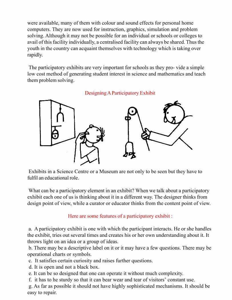
CENTRIPETAL FORCE
Principle : This exhibit works on the combined effect of centripetal force,
gravitational-force and the normal reaction. Construction : This exhibit consists of a
circular frame made from a thick wire passing through two beads. The frame is
connected to a pivot as shown in the figure, and rotated with the help of a drill or a
mechanism similar to a spinning wheel. The beads tend to rise more, the faster the
frame rotates. Both the beads rise symmetrically to a maximum height equal to the
radius of the circular frame. The beads do not rise beyond this point even if the frame
is rotated very fast.
Remarks: The beads attain particular position on the frame under the combined action
of centripetal force to which they are subjected, gravitational force and the normal
reaction due to the frame. When they achieve a height equal to the radius of the frame,
centripetal force and gravitational force, both are at right angles to each other. The
gravitational force on the bead is balanced by the frictional force in the opposite
direction. Material required: A circular frame with two beads as shown in the frame, a
drill, mechanism to rotate the frame.
NEWTON’S CRADLE
Principle : Newton’s cradle works on the principle of conservation of energy and
linear momentum. Construction: Newton’s cradle is made with five similar chrome-
plated steel spheres all having the same diameters and hung symmetrically by strings
from two horizontal rods. These two rods remain parallel and horizontal on a wooden
stand. The spheres should be so suspended that they should be in contact with each
other.
Description : One sphere at one end of the cradle is slightly drawn aside and then
released. On impact, the impulse is carried by the spheres in between and transferred
to the sphere at the other end, which bounces with almost the same energy as the
sphere released earlier. This sphere again strikes the sphere next to it and the impulse is
carried through the spheres in between up to the last sphere which again bounces. The
process continues for quite sometime. Next, the two spheres are pulled together and
released simultaneously. When they hit the sphere at the centre, the two spheres at the
other end bounce. The process is repeated as in the case above when only one sphere
was pulled and released. One can try this experiment by pulling three or even four
spheres on one side and releasing them simultaneously. One interesting observation is
when one or more spheres on each side are pulled (either same or different number of
spheres on either side) and released simultaneously. Remarks: The spheres are identical
and negligible amount of energy is dissipated in the form of sound or heat due to the
impact of these spheres, this represents a case of nearly elastic collision. Elastic
collision is one in which kinetic energy before and after collision is conserved. Hence
after collision, the sphere that bounces has almost the same energy as the sphere that
hit the system. Since the collision is not completely elastic, some energy is lost by way
of sound and heat, and hence the process stops after some time.
Material required : A wooden stand with two horizontal rods as shown in the figure,
five identical chromium-plated steel spheres, thick string to hang these spheres
symmetrically from the two horizontal rods.

GRAVITY TOWER
Principle : The scientific principle involved in this exhibit is that when a body is in
equilibrium, the vertical line (i.e. plumb line) passing through its centre of gravity falls
within its base.
Construction: This is a simple toy, flexible so that its inclination with respect to the
vertical can be changed. (see figure). The centre of gravity of the tower is
approximately at the centre of the middle rod. The plumb line passing through this
point describes a vertical line earring through the centre of gravity. One can observe
how this line shifts as inclination of the tower is changed. The tower is made out of
aluminium strips connected with nuts and bolts that the inclination can be easily
changed.
Description : The tower is kept upright and then slowly the inclination of the tower is
changed. The tower remains stable, until the vertical line passing through the centre of
gravity (also called gravity line) falls within its base. When the inclination is such that
the gravity line (plumb line) falls outside the base, the tower falls down.
Remarks : The gravity tower ca n be used to illustrate the concept of stability. The
stability of the leaning tower of Pisa can be well explained with the help of this tower.
Material required : Aluminium strips, nuts, bolts; plumb line.
CO COUPLED SYSTEMSPLED SYSTEM
Principle: The exhibit illustrates the different modes in which a system
can vibrate. The coupled system described here has two basic modes of
vibration 1) one in which the energy is transferred gradually from one
pendulum to another and vice versa and 2) another in which no exchange
of energy takes place.
Construction: In this exhibit, two identical pendulums are taken and
suspended on a horizontal string which is connected with a wooden
frame (See figure). It is necessary that both the pendulums be identical.
Now one of the pendulums is set into motion by pulling it towards the
performer (keeping the other stationary) and then released gently. The
amplitude of the pendulum set into motion decreases slowly, while the
other pendulum starts oscillating, with its amplitude gradually increasing.
The first pendulum comes to rest eventually when the other one
oscillates with the maximum amplitude. After this, second pendulum
oscillates with a gradual decrease in its amplitude, while the previous one
oscillates with a gradual increase in its amplitude. In this manner the
process is repeated for quite sometime. In another mode, both the
pendulums are pulled either in the same direction or opposite directions
and then simultaneously released. The exhibit thus shows that a system
may vibrate in more than one way.
Remarks : In the system we discussed here, there are two modes of
vibrations. The vibrations eventually die down due to friction.
Material required: Two identical spheres or objects, small wooden rod,
threads, stand, etc.

STATES OF MATTER BOX
MOON PROBE
Principle: Moon probe can be described as a game requiring some degree of skill. It
consists of a wooden frame having some slots at the base with scores marked on
them. It works on the combined effects of gravity and the mechanical force applied by
the performer.
Construction : Two steel rods of the same length are fixed at one end with handles at
the other end. The rods are arranged in such a way that the free ends are moveable in a
rectangular slit are at a slightly higher level than the fixed ends. Both the rods are close
to each other. A steel ball is placed between them at the end where both the rods are
fixed. As one widens the gap between the free ends, the ball tends to roll down and fall
into a slot. The free ends of the rods are now manipulated in such a way that the steel
ball rolls u p to the maximum height and falls in the slot as close to the free end of the
rod as possible (i.e. to a distance as far as possible from the fixed ends).
Remarks : The ball tends to roll down under the influence of gravity. Un- less a jerk is
given to the ball with both the rods, the rolling ball would fall down as the gap between
two gradually increases. The skill lies in giving jerks to the rods so that the ball moves
to the maximum height and falls into slot as close to the free ends of the rods as
possible. One successful in bringing ball farthest from the fixed end in minimum
number of attempts gets maximum marks.
Material required : Two steel rods, with handle at the free ends as shown in the
diagram, wooden frame as shown in the diagram, steel rods, metallic ball.
Principle : This exhibit can be used for describing arrangement of
molecules in solids, liquids or gases.
Construction: A large number of small steel balls (bicycle ball
bearings) are kept in a small wooden frame as shown in the figure,
fixed with a transparent plastic sheet at the top.
Description : If the frame is tilted, the balls come closer and give
rise to a pattern similar to arrangement of molecules in a crystal
lattice of solids. If the frame is kept at the small angle horizontally
and rotated gently, the balls do not form a regular pattern, but,
show some traces of regular arrangement at some places. This
represents the arrangement of molecules in a liquid. If the frame is
vigorously shaken, the balls are set into motion violently, the
distances between the balls also being larger than the previous two
cases. This represents arrangements of molecules in gases.
Remarks : State of matter box can be used to visualise the
arrangement of molecules in the three states of matter viz., solids,
liquids and gases in a qualitative manner.

MOVING SPOT
Three circles having different centre as shown in the drawing provides an excellent
illusion. Hold two knobs at A & B move the board clockwise and anticlockwise. Look
at the spot C. This idea may help you to create an excellent optical illusion display.
CROVA’S DISC
Principle : This interesting exhibit helps in visualising the changes taking place in a
medium when longitudinal waves pass through it, such as sound waves propagating in
the air. As sound waves propagate in the air there a re regions formed called
condensations, the layers or shells of molecules of air moving close together and the
regions called rarefactions, the layers or shells of air molecules moving farther apart.
Construction : Crova’s disc can be made out of a large thick paper of size 25 cm x 25
cm A circle is drawn in the middle of the disc with a radius of 4 mm. and divided into 8
equal parts and numbered sequentially from 1 to 8. Now the compass is placed on
point number 1 and a circle is drawn with a radius of 20 mm. Next, the compass is
placed on number 2 and a circle with radius of 24 mm. drawn. In this manner the
circles are drawn from the successive points every time increasing radius by 4 mm.
After drawing the 8 successive circles, one continues to draw circle as before on the
circumference of the inner circle a second time, increasing the radius by 4 mm. every
time. one may continue a third time also. The disc is cut out and a hole is made in the
centre of disc of the width of a drinking straw. The straw is inserted in the centre of the
disc and spun. If a hand drill is used as shown in the diagram to rotate the disc, the
effect can be much more spectacular.
Description : As one rotates the disc, one sees layers moving together and moving
apart, draw together and separate again, just as when the sound waves pass through the
air.
Remarks : This effect can be observed best by looking through a narrow slit and
covering the disc when it is spun. Material required : A large card 25 x 25 cm drinking
straw or a hand-drill.
MOVING SPOT CROVA’S DISC
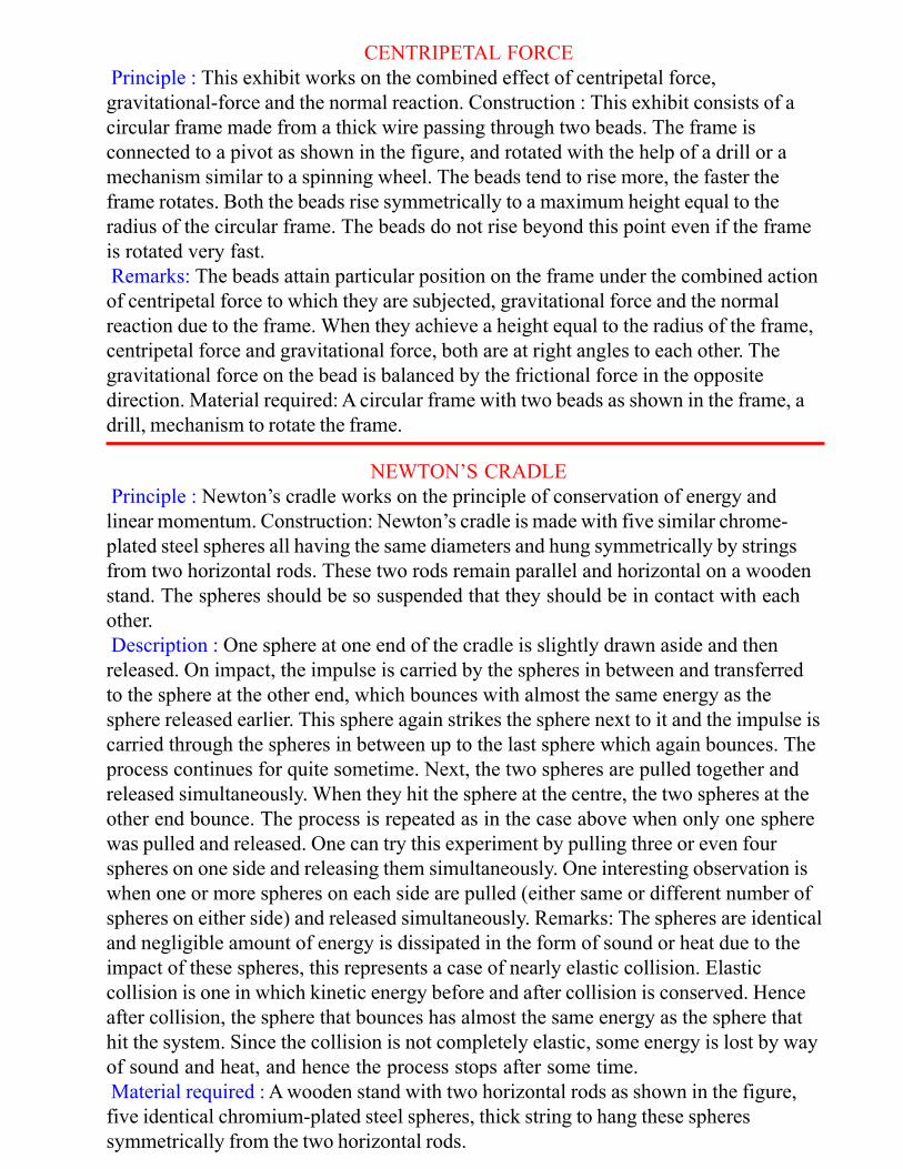
INDIAN ROPE TRICK
MAGIC WINDMI LL
Principle : This exhibit involves the use of a magnet concealed in
a wooden frame.
Construction
Description : Construction of this exhibit is extremely simple. It
involves a wooden frame as shown in the diagram. Two threads
are fixed to iron- pins, or some human shapes cut out from thin
iron foils. The length of the threads should be such as is slightly
short of reaching the top of the frame. A small magnet is
concealed at the top. The pin under the concealed magnet would
remain suspended in the air while the other one would not. The pin
suspended in the air appears highly mysterious since apparently
there is nothing visible which can keep it suspended by pulling it
upwards.
Remarks : It is desired that the magnet concealed in the wooden
frame be of high strength (Alnico or ceramic magnet) since the
force with which the pin is pulled up should be more than the
weight of the pin itself.
Material required: Wooden frame as shown in the diagram, a small
magnet, threads, pins etc.
Principle : This exhibit employs the vibrations in a stick that produce
different rotation phases.
Construction: A wooden stick is taken and notches are made on it at
regular intervals as shown in the figure. At the end of the stick small
propeller: cut from a thin aluminium foil or a thin sheet of wood is
attached with the help of a nail. The nail should, be straight and jammed
into the stick. The hole in which the nail is jammed should be bigger than
the diameter of the nail so that the nail is able to rotate freely in the hole.
With the help of another stick, the notches are struck with the forefinger
and thumb by running it back and forth as shown in the diagram. While
stroking notches, if the forefinger is pressed against the stick, the
propeller will turn in one direction. If, the forefinger is lifted and the
thumb pressed against the stick stroking back and forth, the propeller
will turn in the opposite direction, One can interchange the thumb and the
forefinger in a sly manner causing the propeller to spin in opposite
directions and thus making a great mystery of the whole process.
Remarks : The nail should be able to rotate freely into the hole in which
it is jammed. Otherwise, the magic windmill will not be successful. The
propeller can be made from thin aluminium foil, or a thin wooden sheet.
Material required : A stick with notches at regular intervals, a nail
jammed at one end of the notch, stick, small aluminium foil for propeller.

SOAP FILMS
Principle : Soap films are formed due to surface tension. The films behave like
stretched membranes and are formed such that their surface area is a minimum for a
given boundary. Different types of frames can be prepared from the metallic rods and
beautiful patterns can be obtained with the help of soap films.
Construction : One requires a strong metallic wire such as used in Diwali sparklers
and bent into various shapes as shown in the diagram. For making a particular shape as
shown in the diagram, one may need to solder at some points. Each frame is of
different shape. These frames are dipped into 10% soap solution containing glycerine
15%. When it is lifted one sees beautiful shapes the soap films make.
Remarks : Observe the shapes of the soap films obtained with each frame carefully.
By dipping a frame twice in the soap solution, one may be able to obtain a similar
additional shape within the previous shape of films. Observe the surfaces of the films
obtained, for the inner and outer films. All the surfaces represent surfaces of minimum
area. The answers to many difficult mathematical problems can be given with the help
of soap films (as obtained with the help of different frames in this experiment).
Material required: Some thin metallic rods used in Diwali sparklers, strong soap
solution and thread to suspend the metallic frames.

COLOURS IN BLACK AND WHITE DISC
Principle : Certain parts of our eyes are sensitive only to certain range of colours
depending on the background. The total effect depends on the simultaneous activation
of different part~ of our eyes sensitive to different colours and intensities, and
therefore, the colours we see are the overall effect of these various aspects.
Construction & Description : A disc with alternate black and white sectors on a white
sheet of paper is made (see figure). The disc is spun at low speed to begin with and
one concentrates on it ignoring the individual sectors. The leading edges of the white
sectors would turn red and the trailing edges blue. One can see different colours for
different illumination levels. At faster speed, the whole white sector would be pink red
and a green blue will cover part of the black section. At a still faster speed the colours
cannot be distinguished, but, little sparks of violet pink and green grey light seem to
jump about. The disc shown here would give all three effects simultaneously.
Remarks: There can be several dozens of black and white discs giving rise to different
patterns. When one concentrates on a portion of the disc, the background alternates
between black and white and what one sees is the total effect. To rotate the disc, one
can use a hand drill. One can also use a disc top instead of using a wooden disc.
Material required : Black and white disc as shown in the diagram or having any other
design. A mechanism to rotate the disk (a hand drill would do quite well).

DOUBLE PERISCOPE
Principle : This gadget works on the laws of reflection of light and really two
periscopes combined into one as shown in the diagram.
Construction : The double periscope and a straight tube are placed side by side at the
same level as shown in the diagram. The double periscope is concealed in such a
manner as to make it appear as a single tube. The common stopper is put as shown in
the figure. When the Stopper is absent, one can see through both the tubes. However
when the stopper is inserted one can see only through one tube. The insertion of the
stopper, however, does not affect the double periscope in any way and hence one
continues to see through this tube. This apparently gives rise to a paradoxical situation
that though the stopper is present in the line of sight, one is still able to see through it.
Remarks : In this exhibit, it is important to arrange the tubes of the double periscope in
such a manner as to give the impression of two straight tubes placed side by side. The
entire assembly can be mounted on a platform at a convenient level. Here, it is
necessary to construct the double periscope in a manner such that the mirrors are
placed as close to each other as possible arid at 45-degrees with the horizontal. This is
necessary as larger the path travelled by light, the smaller would be the image. The
exhibit should be made in a manner that the sizes of the image seen through straight
tubes or through double periscope are not significantly different.
Material required: Four plane mirrors, rectangular straight tubes.
M-MIRROR
ELECTRO MAGNET
ELECTROMAGNETIC INDUCTION
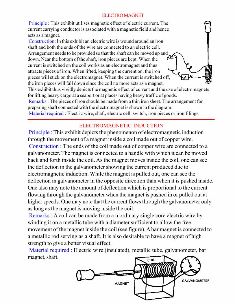
Principle : This exhibit depicts the phenomenon of electromagnetic induction
through the movement of a magnet inside a coil made out of copper wire.
Construction : The ends of the coil made out of copper wire are connected to a
galvanometer. The magnet is connected to a handle with which it can be moved
back and forth inside the coil. As the magnet moves inside the coil, one can see
the deflection in the galvanometer showing the current produced due to
electromagnetic induction. While the magnet is pulled out, one can see the
deflection in galvanometer in the opposite direction than when it is pushed inside.
One also may note the amount of deflection which is proportional to the current
flowing through the galvanometer when the magnet is pushed in or pulled out at
higher speeds. One may note that the current flows through the galvanometer only
as long as the magnet is moving inside the coil.
Remarks : A coil can be made from a n ordinary single core electric wire by
winding it on a metallic tube with a diameter sufficient to allow the free
movement of the magnet inside the coil (see figure). A bar magnet is connected to
a metallic rod serving as a shaft. It is also desirable to have a magnet of high
strength to give a better visual effect.
Material required : Electric wire (insulated), metallic tube, galvanometer, bar
magnet, shaft.
Principle : This exhibit utilises magnetic effect of electric current. The
current carrying conductor is associated with a magnetic field and hence
acts as a magnet.
Construction: In this exhibit an electric wire is wound around an iron
shaft and both the ends of the wire are connected to an electric cell.
Arrangement needs to be provided so that the shaft can be moved up and
down. Near the bottom of the shaft, iron pieces are kept. When the
current is switched on the coil works as an electromagnet and thus
attracts pieces of iron. When lifted, keeping the current on, the iron
pieces will stick on the electromagnet. When the current is switched off,
the iron pieces will fall down since the coil no more acts as a magnet.
This exhibit thus vividly depicts the magnetic effect of current and the use of electromagnets
for lifting heavy cargo at a seaport or at places having heavy traffic of goods.
Remarks : The pieces of iron should be made from a thin iron sheet. The arrangement for
preparing shaft connected with the electromagnet is shown in the diagram.
Material required : Electric wire, shaft, electric cell, switch, iron pieces or iron filings.

Equipment indicating electrical conduction
through materials like wood, plastic, iron wires,
etc. The equipment has a torch battery attached
to electrical circuit. The electrical circuit is
incomplete having two ends A and B, when two
terminals A & B are connected by materials like
iron or aluminium the circuit becomes complete
and the bulb on the line lights up. If the material
is a bad conductor, the light does not light up
DIFFRACTION WITH A SINGLE SLIT
Principle : Diffraction is a phenomenon in which the waves are bent past an edge. This
is why one does not see shadows of objects sharply. If light is passing through a slit,
secondary waves from the same slit interfere and give rise to fringes which are
somewhat similar to interference fringes, as observed in the case of the double slit. The
fringes obtained with the help of a single slit have a bright fringe in the middle and
fringes on either side which fade in intensity as one goes away from the middle fringe.
Also the fringes are not equi-spaced as in the case of interference fringes obtained with
a double slit.
Construction : The construction of single slit is basically the same as that of the
double slit, the only difference being that instead of two slits, one makes a single slit on
a glass plate painted with optically opaque solution. As a matter of fact, the index
finger and the middle finger can also be used to form a single slit and observing
through it would give exactly similar effect.
Description: If one looks at the lamp through the single slit, one can see a bright fringe
in the middle, while the fringes on either side fade in intensity as one goes away from
the middle fringe. If one looks at the white light the middle fringe is white and on either
side of it the fringes appear coloured. However, if one looks at light coming through a
colour filter one sees fringes only of that colour.
Remarks: Diffraction pattern observed with a single slit is different from the
interference pattern obtained with a double slit. The fringes are equi-spaced and of
almost same intensity in an interference pattern, while the spacing and intensity of fringe
change in diffraction pattern. Both diffraction and interference are two typical tests of
wave motion.
Material required : Glass plate, optically opaque solution, single filament lamp, blade,
coloured gelatine filters.

CONSERVATION OF ANGULAR MOMENTUM
Principle : This simple exhibit illustrates the law of conservation of angular momentum
in the absence of external torque.
Construction / Description : This exhibit is basically a conical pendulum. Three beads
each with a hole are taken and a thread passed through all of them. The thread is tied to
both the- beads that are at either end and the middle bead is held in a clamp as shown
in the diagram. Now the hanging bead is set in motion so that the thread describes the
surface of a cone while the bead moves uniformly on the circumference of a circle.
The free bead at the top is then slowly pulled up so that length of the pendulum and
thereby the radius of circle is gradually decreased. One can notice that as the radius of
the circle decreases, the bead rotates faster.
Remarks: In this experiment, one may notice that the thread is pulled upwards and
hence no torque is acting on the bead moving uniformly in a circle. According to the
principle of conservation of angular momentum, so far as there is no external torque
acting, the angular momentum re- mains constant (i.e. product of mass, the square of
the radius and the angular velocity remains constant). Hence as the radius decreases,
the angular velocity of the bead increases and hence it moves faster.
Material required : Three beads, each one with a hole through its centre, twine, clamp.
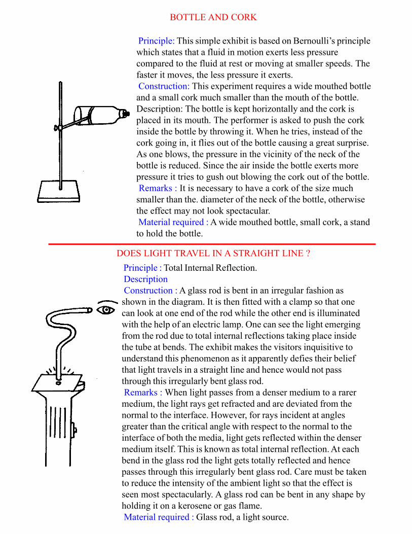
BOTTLE AND CORK
Principle: This simple exhibit is based on Bernoulli’s principle
which states that a fluid in motion exerts less pressure
compared to the fluid at rest or moving at smaller speeds. The
faster it moves, the less pressure it exerts.
Construction: This experiment requires a wide mouthed bottle
and a small cork much smaller than the mouth of the bottle.
Description: The bottle is kept horizontally and the cork is
placed in its mouth. The performer is asked to push the cork
inside the bottle by throwing it. When he tries, instead of the
cork going in, it flies out of the bottle causing a great surprise.
As one blows, the pressure in the vicinity of the neck of the
bottle is reduced. Since the air inside the bottle exerts more
pressure it tries to gush out blowing the cork out of the bottle.
Remarks : It is necessary to have a cork of the size much
smaller than the. diameter of the neck of the bottle, otherwise
the effect may not look spectacular.
Material required : A wide mouthed bottle, small cork, a stand
to hold the bottle.
DOES LIGHT TRAVEL IN A STRAIGHT LINE ?
Principle : Total Internal Reflection.
Description
Construction : A glass rod is bent in an irregular fashion as
shown in the diagram. It is then fitted with a clamp so that one
can look at one end of the rod while the other end is illuminated
with the help of an electric lamp. One can see the light emerging
from the rod due to total internal reflections taking place inside
the tube at bends. The exhibit makes the visitors inquisitive to
understand this phenomenon as it apparently defies their belief
that light travels in a straight line and hence would not pass
through this irregularly bent glass rod.
Remarks : When light passes from a denser medium to a rarer
medium, the light rays get refracted and are deviated from the
normal to the interface. However, for rays incident at angles
greater than the critical angle with respect to the normal to the
interface of both the media, light gets reflected within the denser
medium itself. This is known as total internal reflection. At each
bend in the glass rod the light gets totally reflected and hence
passes through this irregularly bent glass rod. Care must be taken
to reduce the intensity of the ambient light so that the effect is
seen most spectacularly. A glass rod can be bent in any shape by
holding it on a kerosene or gas flame.
Material required : Glass rod, a light source.

GLASS AND COIN
Principle : This exhibit is based on Bernoulli’s principle which states that a fluid
(liquid or gas) in motion exerts less pressure compared to fluid at rest or flowing at
smaller speeds.
Description : A glass is held in a stand as shown in the diagram. A thin metallic disc
similar to a ten paise coin is kept about 10 cm away from it, on a table or a plain
surface. The visitor is asked to put the coin in the glass without touching it. If he
cannot do it he is asked to blow over it. In a spectacular fashion, the coin flies into
the glass. When one blows over the coin, the air in the vicinity is set in motion and
the pressure drops. The coin is lifted by the air below it which is at a higher pressure
(since it is at rest), gains momentum due to the air in motion above and flies into the
glass.
Remarks : It requires some skill to blow the coin into the glass. This exhibit can
also be presented in the form of a game. One is asked to blow the coin into the
glass for the maximum number of times in the minimum number of attempts.
Material required : A coin, a glass and a stand.

MOIRE PATTERNS
Principle: A Moiré pattern can be obtained by superimposing two pat- terns of
slightly different periodicities. It can be used to study the structure of crystals,
interference phenomena and also to study defects of lenses. Moiré patterns have
served several other interesting applications in fabric Industry.
Construction : In this exhibit, two Moiré patterns have been described. One has
equally spaced parallel lines on two transparent sheets. The lines may be marked
with the help of magic markers on the sheets. The sheets are held one over the
other and moved relative to each other or rotated. Intersection of the two figures
produce large changes in the spacing of the Moiré fringes. Another simple Moiré
pattern can be prepared by drawing equally spaced parallel lines when the spacing
on one set differs from that of another.
Beautiful Moiré can be prepared based on circles. Identical sets of circles are
drawn on two transparent sheets by increasing radius at regular intervals. The
circle should be somewhat thick. One sheet is placed over the other. As two sets
of overlapping circles move apart, one sees a radiating Moiré pattern. These
Moiré duplicate interference patterns produced when light waves from a common
source pass through two pinholes.
Remarks : Moiré is a French word for ‘watered’, in English it is most frequently
heard in the term of ‘Moiré Silk’, a fabric that has a shimmering appearance
resembling the reflections on the surface of a pool of water. One can see Moiré
pattern by folding nylon cloth and seeing through it. Two identical photographic
negatives also can be used to produce Moiré patterns. It is possible to produce
Moiré pattern by overlaying pattern on a transparent sheet onto a pattern on an
opaque sheet.
Material required : Transparent sheets, magic markers, etc.

PARROT AND CAGE
Principle : Persistence of Vision
Construction : This exhibit is based on an old traditional toy called (Popat Pinjar) In
this toy a coin would have a parrot image on one side and cage image on other side.
Keeping its popularity in mind the present revolving plate with parrot on one side and
cage on another side was designed. A metal plate about 25 cm. in height 18 cm. in
width (approx.) is fixed on a revolving circular base. The plate has on side A,
PARROT figure and on side B, CAGE figure. The Plate is turned by revolving head of
a hand drill which is fixed on the top of the pedestal. Almost all pedestals have 60 cm
to 75 cm height.
Remarks : Along with this big sized exhibit we also have a very inexpensive carry
home toy ‘Parrot and Cage’.
Materials : Metal plate, iron wire, hand drill, wood, colour.
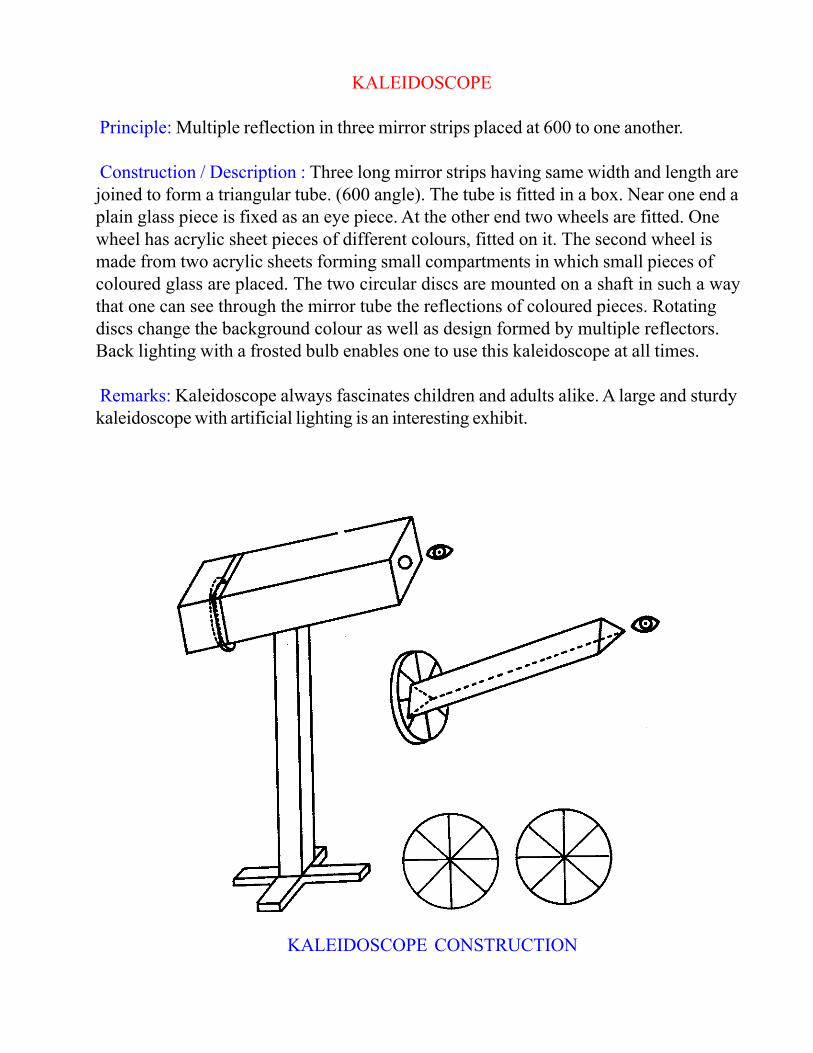
KALEIDOSCOPE
Principle: Multiple reflection in three mirror strips placed at 600 to one another.
Construction / Description : Three long mirror strips having same width and length are
joined to form a triangular tube. (600 angle). The tube is fitted in a box. Near one end a
plain glass piece is fixed as an eye piece. At the other end two wheels are fitted. One
wheel has acrylic sheet pieces of different colours, fitted on it. The second wheel is
made from two acrylic sheets forming small compartments in which small pieces of
coloured glass are placed. The two circular discs are mounted on a shaft in such a way
that one can see through the mirror tube the reflections of coloured pieces. Rotating
discs change the background colour as well as design formed by multiple reflectors.
Back lighting with a frosted bulb enables one to use this kaleidoscope at all times.
Remarks: Kaleidoscope always fascinates children and adults alike. A large and sturdy
kaleidoscope with artificial lighting is an interesting exhibit.
KALEIDOSCOPE CONSTRUCTION

QUICKER DESCENT
What it is? : It is a gadget to illustrate the paradox that the shortest distance (straight
line) between two points need not be the path of quickest motion.
A big wooden frame in the form of a right angle has two points, one at the upper end
and the other at the lower extremity, joined by smooth rods, one perfectly straight and
the other in the form of an are of a curve called cycloid. There is a heavy knob which
can slide smoothly on each rod.
How it works : There is a contrivance which can hold both knobs at the highest point
and can release them at the same time. Release them in this way and let them slide
down the rods under gravity. You may be surprised to see that the knob sliding down
the cycloid reached the other extremity earlier than the other knob sliding down the
straight rod. A longer distance is covered in a shorter time under similar conditions.
Conclusion: Though the straight line is the shortest distance between two points at
different levels, the time of descent form one point to the other is less along a cycloidal
are joining the points than along the straight line.
PERIODIC TABLE
Principle: The properties of elements change gradually in vertical and horizontal rows
of the periodic table.
Construction : A framework is made from wood in the form of a periodic table. In
place of each element a cube can be inserted. This cube can move about a vertical axis
on a pivot. The four faces on the cubes exposed to viewer are painted with four
colours, e.g. yellow, red, green and blue. On same coloured face similar properties of
elements a re painted e.g. symbol, physical state, atomic number and atomic weight are
painted on yellow face. The periodic table in toy form is then assembled.
Remarks : Several questions can be put near the periodic table.
a) Which elements are metals? (hint metals have low ionization energy)
b) Which is the densest element?
c) Which elements are gaseous?

DO ALL LIQUIDS MAINTAIN LEVEL?
ELECTROLYSIS OF WATER
Principle : Passage of 6 Volt D.C. electric current through water leads to its electrolysis
resulting in the formation of hydrogen and oxygen gas.
4 H+ + 4 e——— 2H2
4 OH—2H20 + 0
2 +4e
Construction
Description : This glass equipment is made from coming or Pyrex glass by a glass
blower. The electrodes are 1 cm x 1 cm platinum and are fused into the glass as shown
in the diagram. The two arms are constructed from burettes.
Principle: All pure liquids or homogeneous liquids maintain the same
level. In second U tube the levels are different because one arm
contains alcohol while the other arm contains water. Both have different
densities. As liquids are coloured to the same extent and they are
miscible in one another, no interface is seen and they look like the same
liquid. The tube maintains different levels for more than three months.
The alcohol solution evaporates out and a fresh solution should be
added every two weeks.
Exhibit: Mount U tubes on a plywood panel keeping the bottom bend
visible. Make a solution of a pinch of methylene blue in about 30 ml
alcohol. Take-100 ml water and 100 ml alcohol in two separate beakers.
To both water and alcohol add equal amounts of methylene blue
solution say 10 ml each. Shake the solutions to make them homogeneous. To one U
tube add methylene blue solution in water. This solution will maintain same level. To the
other U tube add methylene blue solution in water till the tube is about half filled. Now
fill the remaining portion by adding methylene blue solution in alcohol. This tube will
have different levels of liquid in the two arms.
Material required : 2 U tube of about 1 meter height, ethyl alcohol, water, methylene
blue.
Activity: The electrodes are connected to 6 V D.C.
supply. The 6 V D.C. supply can be obtained from
a battery eliminator or from a battery box in which
four, 1.5 volt cells are joined in a series. The
electrolysis apparatus is filled with water and a
small amount of sulphuric acid. On pressing the
switch electrons flow through electrodes and split
water into hydrogen and oxygen. The relative
volumes of hydrogen and oxygen gases could be
read from the burette.

WAVES
Principle : Conversion of potential energy of two liquids to kinetic energy results in the
opposite movement of liquid layers which result in wave formations.
Construction / Description : A long narrow platform is made form a wooden plank. In
the Centre of this platform is fitted a pivot. A long glass tube with one opening is fined
on a plank and joined to the pivot. On the two ends of platform are placed foam
rubber cushions which keep the glass tubing in horizontal position. The end of the tube
can be pressed down over foam rubber. On releasing, the two liquids in the tube move
in opposite direction forming waves.
Material : Methanol, liquid hydrocarbon such as petrol or kerosene, a small amount of
methylene blue.
Setting up: Take methanol add a small amount of methylene blue to make a transparent
blue solution. Add to the glass tube with a funnel till the tube is filled nearly half. Fill the
tube completely with hydrocarbon liquid and stopper with a glass stopper having a
hole in it. Some liquid is lost due to evaporation. Fill the tube completely by injecting
hydrocarbon liquid through the hole with the help of a syringe as and when necessary.

MAGIC BOTTLE
Principle : Methylene blue is reduced to a colourless form by the action of glucose in
an alkaline solution. On shaking the methylene blue in contact with the oxygen in the air,
it gets oxidised to a blue form. This can be repeated several times during 24 hours with
the same solution. If the liquid does not become blue on shaking,· remove the cork and
allow fresh air to get into the bottle.
WINDOW READER
What is it ? This consists of an open square box, three square slotted plates and a
plate containing all the numbers from l to 64.
What it does ? Think of any number from 1 to 64. Using these plates we can see the
chosen number through a small window.
How to use it ? Find on which edge of the three plates the chosen number occurs.
Arrange the plates in the box in any order so that these edges are at the top. Cover the
box with the numbered plate and turn the whole gadget to see the chosen number
through a small window.
How it works ? Note that each slotted plate covers three-fourths of the visible
numbers on the number plate. When all the three plates are thus used the number of
numbers exposed to view is 64 x 1/4 x 1/4 x 1/4 = 1.
Examine the pattern and shape of the slots in each plate.
If liquid does not become colourless in the beginning add a
small amount of glucose and
or sodium hydroxide and wait for 2-3 minutes. Using Indigo
carmine instead of methylene blue gives two changes of colour -
yellow on one shake and red on vigorous shaking.
Exhibit: Take about 150 ml water in the bottle. Add sodium
hydroxide, glucose and a small pinch of methylene blue to the
bottle. Shake and allow to stand. After a few minutes, the liquid
will become colourless. Shake the bottle. The liquid will turn
blue. Again on standing, the liquid becomes colourless.
Material required: Narrow mouthed bottle of about 500 ml
capacity. 5 gm sodium hydroxide, 5 gm glucose, pinch of
methylene blue, cork to close the bottle.
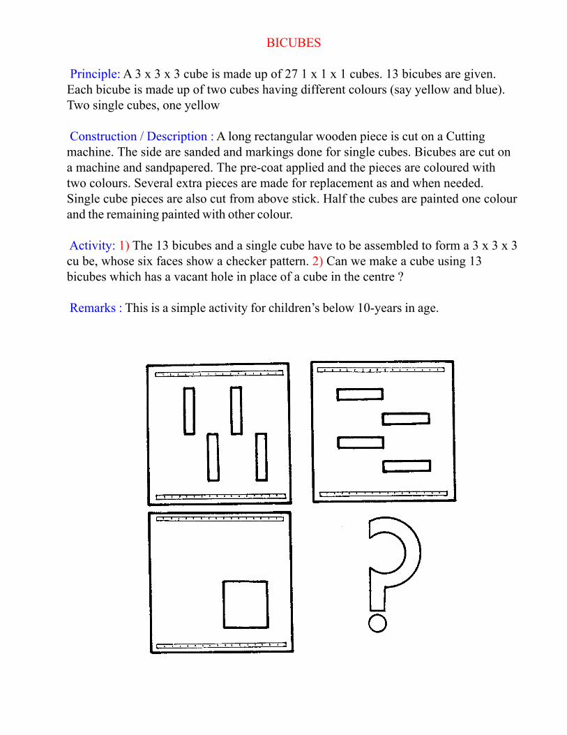
BICUBES
Principle: A 3 x 3 x 3 cube is made up of 27 1 x 1 x 1 cubes. 13 bicubes are given.
Each bicube is made up of two cubes having different colours (say yellow and blue).
Two single cubes, one yellow
Construction / Description : A long rectangular wooden piece is cut on a Cutting
machine. The side are sanded and markings done for single cubes. Bicubes are cut on
a machine and sandpapered. The pre-coat applied and the pieces are coloured with
two colours. Several extra pieces are made for replacement as and when needed.
Single cube pieces are also cut from above stick. Half the cubes are painted one colour
and the remaining painted with other colour.
Activity: 1) The 13 bicubes and a single cube have to be assembled to form a 3 x 3 x 3
cu be, whose six faces show a checker pattern. 2) Can we make a cube using 13
bicubes which has a vacant hole in place of a cube in the centre ?
Remarks : This is a simple activity for children’s below 10-years in age.

BULL’S EYE
What is it ? This consists of eleven square wooden plates and a 3 x 4 rectangular tray
which can accommodate these square plates leaving one square space empty.
The Problem : Arrange the plates in the tray in such a way that the white circle is
formed by the arcs on eight of the plates, the centre of the circle being occupied by a
blank square, all in the top nine squares. In the bottom row, the left hand square is
blank, the middle square is the one which contains the dot and the right hand square
space is empty. Beginning with this position, slide the squares successively in the
empty spaces until the circle is restored and the dotted so u a re is in the centre of the
circle.
Solution :
ROLLING CUBES
What is it ? There are eight cubes placed in a square tray in 3 x 3 formation with the
space for the central cube vacant. Each cube has a red face and a blue face opposite
each other and the remaining four faces are white.
The Problem : Begin by placing the cubes with all the red faces on top, with the
central space empty. Roll the cubes one after another about a lower edge in the empty
space. Do this until all the blue faces are on top and the empty space is in the centre.
Note that no sliding of the cubes is allowed, only rolling about a lower edge is to be
done.
Solution: The solution is given below. There are 36 moves. Each letter represents a
move of the cube with reference to the empty space
A R B L L B R R A L B L A= Above
A R B R A L B L A A R B B = Below
R A L B R B L A L B R A L =Left R =Right
Comments : The problem had appeared some time back in the “Scientific American”.
The solution given above was first obtained with the aid of a computer. Solutions by
human effort were also there, but the number of moves was more than 36. The
problem is generally considered very difficult.
The four unmarked squares are not to be disturbed. The plates occupying The
squares denoted by the following letters are to be successfully moved in the adjacent
empty spaces.
D E H G F E B
A F G H E D C

PARKING PUZZLE
What is it ? This is a wooden box-like gadget in which there are grooves as shown in
the figure. There are six counters which can move along the grooves.
The Problem : Place the three yellow counters on A, B, C and the blue counters on X,
Y, Z. Move the counters one by one until the three yellow counters change places with
the three blue counters, moving one counter at a time.
Hints : Use the parking place 0, and B,P,Q,Y as parking places whenever They are
available. Any counter left at R will be a hindrance to the movement of the other
counters.
Solution : In the following solution each pair of letters indicates the move of a counter
from the first letter to the second. The minimum number of moves is 17.
BO YB ZP OZ PY BQ
CO OC YB XP OX PY
BO AO QA YB OY
Comments: There is an extended form of this problem. We may have, instead of three
yellow and three blue counters, five yellow and five blue counters on the two sides.
Here the number of moves required for the exchange of the counters is greater and the
solution is naturally more difficult but it is worth trying.

STRING BEAD PUZZLE
What is it? it consists of a frame with three holes A, B, C on the top board. A long
string with two large buttons attached to the two ends, pass through the holes A and C
and with the middle portion of the string is looped through the middle hole and back
on itself. There are two beads through which the string passes in each of the two loops
as shown in the figure. The two beads are thus kept separate by the middle loop.
The Problem : Undo the middle loop and bring the beads together. Solution : Catch
hold of the middle loop, put it under the left bead, thread it up the hole A, pass it over
the button and pull it down. Repeat this process for the other bead. Pull down the
thread and you will see the two beads coming together.
Comments : This is a topological problem and is one among many string and bead
puzzles.
‘You know what I like about this place is that I can lay my
hands on things I want to do !’
—a child’s opinion

BRAHMA’S TOWER
What is it? It consists of 3 pegs 1, 2, 3 and five circular discs of different sizes and
preferably of different colours, each with a hole in the centre.
The Problem : To start with, all the five discs are placed on peg 1 with the largest disc
at the bottom and the smallest on the top in the order of their sizes. The problem is to
transfer the five discs from peg 1 to peg 3 using the peg 2 for intermediary moves. The
following conditions must be followed
1) Move only one disc at a time
2) No disc can be placed over a smaller one.
Solution : The transfer can be effected in 31 moves. In the following solution each pair
of digits indicates a move of a top disc from the peg given by the first digit to the peg
indicated by the second digit.
13 12 32 13 21 23 13 12
32 31 21 32 13 12 32 13
21 23 13 21 32 31 21 23
13 12 32 13 21 23 13
Comments : Had there been only four discs the number of moves would be 15. For
three discs the number is 7 and for 6 discs the number is 63. Mathematicians many be
interested in proving the general formula for the number of moves for n discs. This
number is 2n - 1.
History: Mythologists say that Brahma had ordained a tower like this with 64 discs. It
is said that a number of great Rishis sitting around a sacrificial fire were asked to
transfer these discs according to rules from one peg to another using a third peg for
intermediary moves, so that all the discs are transferred in the above manner. The
number of moves required for this is 264 - 1. Calculating at the rate of ten discs per
minute the total time required for the complete transfer of discs will be several billions
of years. The work of transfer of the discs was stipulated to start when the earth’ was
created. It is said that when the last disc will be transferred, there will be a thunderclap
and a deluge and the earth will vanish. The process of the disc transfer is supposed to
be still going on.

INTERLOCKED LOOPS
What is it ? It is a topological problem. Two long ropes which are tied to the hands of
a boy and a girl standing opposite to each other are interlocked.
Problem : Undo the interlocked loops, that is, separate the boy and the girl.
How is it done ? First note that the knotted loop round each of the four wrists is wide
enough to let more than a rope pass through, but not so wide as to let the loop come
off the hand.
Now at the place of the interlock, catch hold of the rope that lies below the other take
it towards the hand on the same side, pass it through the knotted loops below that
hand from behind, pull it over the fingers above the hand and finally draw it through the
knotted loop, releasing it from the interlock.
Comments : After separating the two ropes, you have the reverse problem of
interlocking the ropes back to the original position.
In the beginning of the solution, if you had picked up the other rope (i.e. the one
which lies above) and proceeded as above what will happen? You will make the
interlock more complicated. Try and see. How will you then resolve the complication ?

SOMA CUBE
What is it ? Seven wooden shapes made up of small cubes as shown in the figure are
given.
The Problem : These blocks are to be assembled together to make a cube. As there
are 27 small cubes in all, the final cube will be a 3 x 3 x 3 cube.
Hint for Solution : See the figure
Comments : These blocks can be used to make many other shapes. Some of them are
given below.
INSANITY BLOCKS
What is it ? Four equal cubes have their faces coloured by four different colours in
different ways and they are placed in a small long tray.
The Problem : The cube should be so arranged in the tray so that all the four colours
appear on each long side of assembly.
Hints : Count the number of each colour on the face of each cube. As four of each
colour have to appear on the long sides of the assembly, we know what colours should
go on the faces in contact (invisible) and on the two ends. After this, arrange the cubes
with this condition satisfied and turn the cubes about the long axis of the assembly until
the condition of the problem is satisfied.
Solution : A solution is shown in the figure.
Comments: There is also a beautiful solution using graph theory. But this solution
cannot be given here.
R = RED
B = BLUE
Y = YELLOW
G = GREEN

TROMINO FITTING
What is it ? A tromino is a 3 x 1 rectangle i.e. three unit squares joined edge to edge in
a straight line. An 8 x 8 square tray and 21 trominoes are given. Problem:
Accommodate the trominoes without overlapping in the tray leaving one unit square
space vacant.
Hint: The trominoes cannot be fitted in the tray if the vacant square is arbitrarily chose
n. The vacant square has to be one particular square in the tray or any of the three
symmetrically situated with this square. You will have to find one of these four squares.
Solution : You may arrange the trominoes in any one of many ways provided the
vacant square is one of the four shaded square shown in fig u re 1. One solution is
shown in figure 2.
Comments : Here we give the reason why only a shaded square in figure 1 can be
vacant for a successful solution. Let us mark every unit square in the tray by one of the
digits 1,2 or 3 according to the scheme shown in figure 3. Then note that a tromino
placed anywhere in the tray so as to cover three unit squares, will always cover each of
the three digits 1,2,3. So, in the correct solution, 21 of each of the digits will be
covered. However, it is seen that in the tray, the number of 2’s and 3’s a re each 21,
but the number of 1’s is 22. Hence the vacant square must bear the number 1 and all
the other three squares symmetrical with this must also bear number 1. It is easy to see
that the only squares which ca n be vacant are those shown in figure 1. Fig. l
Fig 3
Fig 2Fig 1

HYPERBOLOID
AME’S CHAIR
What is it ? An optical illusion. Look through the eye-piece. Inside the box, you see
what appears like a little chair. Now, open the side-door and look inside. You see no
chair, but a number of short sticks haphazardly suspended, and a picture of a seat on a
black vertical screen. Explanation: The illusion caused by the perception is due to
conical projection .
Construction : A number of thin straight black wires emanate from near and behind the
eye-piece and end at certain points on the black vertical screen at the far end of the
box. These points are certain critical points on the outline of a chair, previously drawn
on the back of the screen. Then, a suitable number of thin white sticks are placed in
any convenient position between such pairs of wires as will correspond to the limb of a
chair, an arm, a leg etc., gluing the ends of the sticks with the wires. A picture of a seat
of the chair drawn on a paper suitably as to size and shape is either pasted on the
screen at the appropriate place or placed with the four corners on the appropriate
wires.
How and Why it works: To enhance the illusion, the screen and wires should be
preferably black and the sticks white (match-sticks with the phosphorous removed
may be ideal). Greased glass or translucent paper may be used for the sides of the
box, so that the inside of the box gets diffused light. The single eye piece allows only
one-eye-view and eliminates stereoscopic (or depth) effect. Thus, the 3-D objects are
identified with their 2-D projections on the screen.
What is it ? This is a gadget which an help one to visualise
the surface of a Hyperboloid of one sheet.
Construction : Two equal circular discs a re connected
with each other by a straight vertical rod joining the centres
of the discs which are in horizontal positions. Three points
equally spaced on the rim of the upper disc are joined to
three points equally spaced on the rim of the lower disc by
means of three slanting rigid rods. The whole gadget is
mounted on a turntable.
How it works ? Rotate the gadget rapidly by turning the
handle. The successive positions of the slanting rods in
motion give the impression of a curved surf ace which is
known as a Hyperboloid of one sheet.
PARTICIPATORY EXHIBITS FOR YOUNG ONES
Although basic principles of design remain the same, there are certain special
considerations for the younger age group.
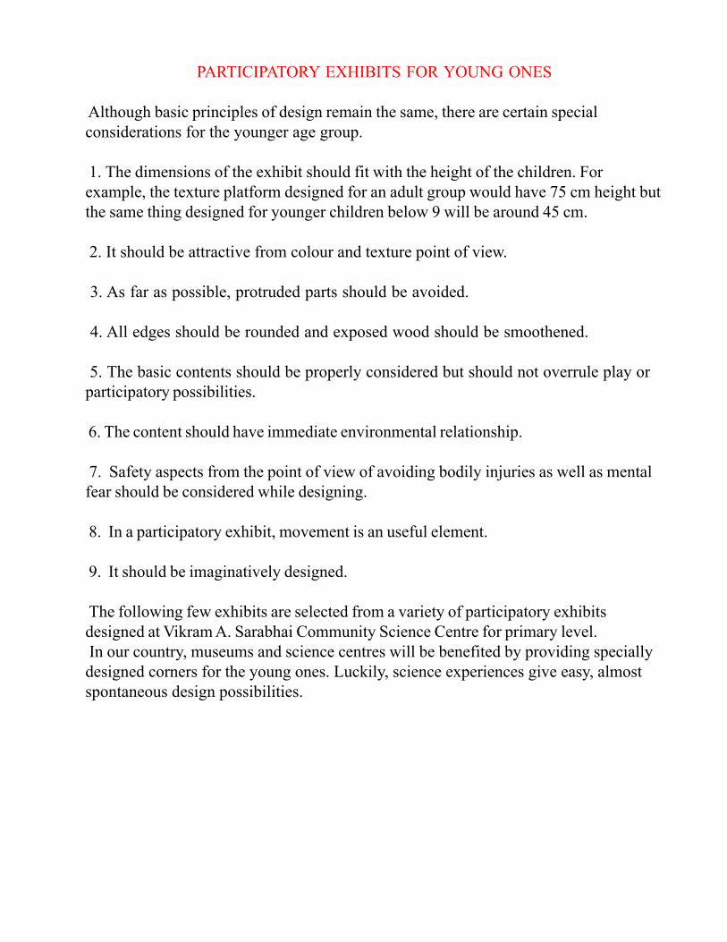
1. The dimensions of the exhibit should fit with the height of the children. For
example, the texture platform designed for an adult group would have 75 cm height but
the same thing designed for younger children below 9 will be around 45 cm.
2. It should be attractive from colour and texture point of view.
3. As far as possible, protruded parts should be avoided.
4. All edges should be rounded and exposed wood should be smoothened.
5. The basic contents should be properly considered but should not overrule play or
participatory possibilities.
6. The content should have immediate environmental relationship.
7. Safety aspects from the point of view of avoiding bodily injuries as well as mental
fear should be considered while designing.
8. In a participatory exhibit, movement is an useful element.
9. It should be imaginatively designed.
The following few exhibits are selected from a variety of participatory exhibits
designed at Vikram A. Sarabhai Community Science Centre for primary level.
In our country, museums and science centres will be benefited by providing specially
designed corners for the young ones. Luckily, science experiences give easy, almost
spontaneous design possibilities.

TEXTURE PLATFORM
Objectives : To provide experiences of various textures to young ones. — To make
them feel and recognise differences in various textures.
Construction : 90cm x 90cm. surface divided into 9 equal parts. Each part will have
texture like 1. Silk 2. Velvet 3. Wool 4. Rough sand surface 5. Medium rough sand
surface 6. Very rough sand surface 7. Wood 8. Rubber 9. Plastic Height is
approximately 45 cm.
The surfaces are made in different ways. i.e. — Sand is sieved into three different
grades and applied to wood with synthetic adhesives.
— Silk, wool and velvet fabrics are stretched on 12 mm. ply and then the ply is nailed
to the hardboard base of the platform.
— Rubber, wood and plastic surfaces were the original pieces of materials.
Description: Even though the child will use the surfaces by himself or herself, a little
interaction or questioning will make the experience more involving.
Questioning can vary with various age groups, e.g. 4 to 5 years age groups will be
willing to answer the following types of questions:
a) Which is the roughest surface? b) Which do you think is the cloth here?
Note : Materials for textures may change from time to time, to keep up novelty. Height
and other measurements may also slightly vary according to materials available.
Materials : Plywood or old packing wood, synthetic adhesive and various materials
with differing textures.

TOUCH AND JUDGE BOX
Objectives : To make children feel different things without seeing them and connect
this experience with things they can spot in the surrounding. Things like stone,
coconut, shells, feathers, cotton.
To provide younger children an exercise for judging materials through Blind box
experience.
To provide a “hand on things” exhibit for juniors in a general display area.
Construction : Box has following broad dimensions.
Height : 120 cm Breadth : 90 cm
Holes : 15 cm No. of holes : 9 per box
All wood work will have rounded edges. Each hole has detachable cotton washable
bag in which different objects can be hidden.
Description : The box can be used by two to three children at a time. The child is
asked to put the hand into the hiding bag via the hole. After feeling an object, the child
will judge the object and select an identical object from the tray nearby. Each object in
the tray will have a string and the child will put an object on a relevant peg near each
hole.
Note: The objects can be changed from time to time to suit levels and relative
complexity:
Materials: Ply wood or any used cotton cloth, wood, paints, things like feather, cotton,
stone, seeds.

‘SEEING BIG’ TABLE
Objective : 1) To provide a device through which children can see magnified images of
different things. 2) To satisfy children’s curiosity in observing details of different
materials.
Construction: A table with approximately the following dimensions. Height - 45 cm
length and breadth - 90 cm The table will have a central rod on which a revolving
handle with a magnifying glass can be fitted. The height of the rod can be fixed
according to the focal length of the lens used.
Materials can be placed on clean surfaces. They should be on the circles which will
fall under the rotation of the lens. This gives them a certain easiness and pleasure in
handling.
Description: The things can be chosen according to the age level and environment.
Children can be given an activity to observe these things magnified and then they can
write or draw those things. Things like a live cockroach or an ant interests children for
observing structure, and movement. Veins in different leaves can also be studied.
Note : 1) The construction should be extremely sturdy because it is noted that this
sort of device has great wear and tear. 2) Spare magnifying lenses are required.
Materials : Plywood or packing crates wood, metal rods, magnifying glasses, display
plates with lids.
Thing s like insects, leaves, flowers, pebbles, sand, seeds, wood.

NUMBER PATTERN
Objective : 1) To provide experiences of finding out the patterns in numbers appearing
on the tray. 2) To make children think of numbers and their relations with other
numbers and to find out the correct position of a plate on the tray.
Construction : There is a wooden tray. 1 to 100 numbers are written on it. There are
10 wooden plates which can be placed on the tray only one at a time. On these plates,
the re a re h o les at different points.
Description : A child can take one plate at a time and put it on the number tray. He has
to find out the pattern in the appearing numbers. If he can not make out the pattern, he
can change the position of a plate. He has to find out the mathematical relations among
all the numbers appearing. One plate can have holes for prime numbers, others have
holes for multiplication tables, and so on. A plate with holes using multiplication table 9
will look as shown when placed correctly on the tray.
Note: Children can make their own plates with some number patterns. Pattern plates
can be made using some series of numbers and can be given as problems.
Materials : Plywood, old packing wood, ink to write numbers on the tray.

OPTICAL ILLUSION EXHIBITS
Optical illusions make excellent participatory exhibits. 45 x 45 cm square modular is
suitable for many static graphics.
Exhibits which require turning or making upside down position can be fixed on a
sturdy panel with turn table type of pivot.
For measuring width of parallel lines a measuring scale can be hung by the side of an
exhibit.
The graphic should be suitably enlarged according to the size of the board.
FIND OUT THE
HIDDEN MEN
WHICH CIRCLE IS BIGGER?
JUDGE AND THEN MEASURE.
Hold the board with above graphic at A and B.
Turn it clockwise and anti-clockwise. Do it at
various speeds. Observe the centre of the circle
and see what happens to the lines.
This is a traditional optical illusion.
Turn it upside down and see.

REVOLVING WINDOW
What is it ? It is a model of a window frame mounted on a vertical axis about which it
can turn. An example of an optical illusion.
What is the illusion? Stand at a distance of about 5 meters from the gadget and look
when the gadget is switched on. Do you see the window frame wobbling ? It appears
to turn from one side to the other and back alternately. Walk up and stand close to the
gadget and look again. You see it is not wobbling, but, in reality, revolving about its
axis continuously. Why did it appear like wobbling when seen from a distance?
Explanation: This is based on the simple fact that any object appears Smaller from a
greater distance and bigger from a lesser distance. Note that The window frame has not
the normal rectangular shape, but is a trapezium, the two vertical edges having slightly
unequal lengths. Every time the longer vertical edge moves further away from observer,
it appears a little shorter, while the opposite edge looks a little longer, when seen from a
distance. This occurs repeatedly in a continuous revolving motion of the window frame
and thus produces the illusory wobbling effect. Experimentally find out the optimum
distance where one should stand at which a slight displacement of the observer
switched the wobbling effect into the real revolving effect.
a. The playground equipment should excite the children to play.
b. It should give them some physical activities like climbing, bending, running, etc.
c. The child should be able to experience some scientific phenomenon during the play.
d. The playthings should be simple and sturdy and should provide varying play
opportunities.
e. It should work as a prototype for establishing similar playgrounds elsewhere.
‘If museums are in communication business as they purport to be, it is worth inquiring
what is in fact, being communicated!’

SCIENCE PLAYGROUND
“Science Playground” is a recent experiment to initiate children into the world of
science through interesting outdoor participatory activities.
India is a vast country with a bewildering variety of socio-economic groups. The
Indian rural scene is very different from the Indian urban scene. Each group has its
own characteristic traditions and needs. Vikram A. Sarabhai Community Science
Centre (VASCSC) broadly keeps the needs of rural and urban groups in mind in
organising its programmes. Science playground is one programme which is developed
and designed in a way that it can be used by groups with various backgrounds. As
such, there are really no organised playgrounds in Indian cities. Some of them do have
playgrounds; but a playground as an essential need for the growth of mental faculties
of children has still to be recognised and therefore the playground as a facility does not
have a priority in the educational programme. Yet a few conscious groups have
recognised this very vital aspect o’ children’s life and have developed a few
playgrounds. VASCSC science playground is one with such an objective.
What are the features of a science playground vis-à-vis an ordinary playground? The
present playground is exactly a play strip measuring about 12m x 30m. It is on the west
side of the premises and children go to the play ground very informally whenever they
like a change of the activities which take place at the Centre. Morning times are cooler
and shadier. The playground is basically designed with the following objectives in
mind.
The VASCSC science playground has the following
1. Colour Filters
2. Colour Mixers
3. Temperature Blocks
4. Singing Pipes
5. Measuring Sand pits
6. Evolution Pillar
7. Simple machines
8. Gears, Pulley
9. Texture block (Vegetation, Shells and geometric patterns)
Before designing a plaything, two major aspects are considered
1. Content Aspect
2. Design Aspect
The content aspect is handled by the designer and scientific collaborate together.
The design aspect is handled by the design fabrication draughtsmen. The team
consists of three basic skills :

1. Science Collaborator having science educational activities background.
2. Design collaborator having educational activities background
3. Fabrication draughtsmen.
Most of the methods and materials used in fabrication are of local origin and particular
stress is given to materials like bricks and sand. For the materials are used for their
sturdiness and cleanliness. Gujarat region where we have been developing these ideas,
has a rich craftsmen tradition. The point of view of the craftsmen is also considered
while deciding the details of the design.
COLOUR FILTERS
Colour Filters are a group of 3 block structures having several peeping holes cast in
concrete. These holes have various colour filters. Children and adults alike enjoy the
play activity while peeping in the different colour viewers to look at pillars painted in
seven different colours. There are several colour filter viewers provided and a group of
children can use them very informally.
COLOUR MIXER
These also are fixed structures, very simple and sturdily built which will permit colour
mixing of primary colours. These playthings give perpetual pleasure to most of the
children. Average height of these colour filter structure is 165 cm.
Colour Filter structures basically permit physical activities like seeing, manipulating,
bending, touching. Apart from the pillars having colour filter play factors, they also
have hide and seek facility and quite sometimes children use it as a hide and seek
plaything also.
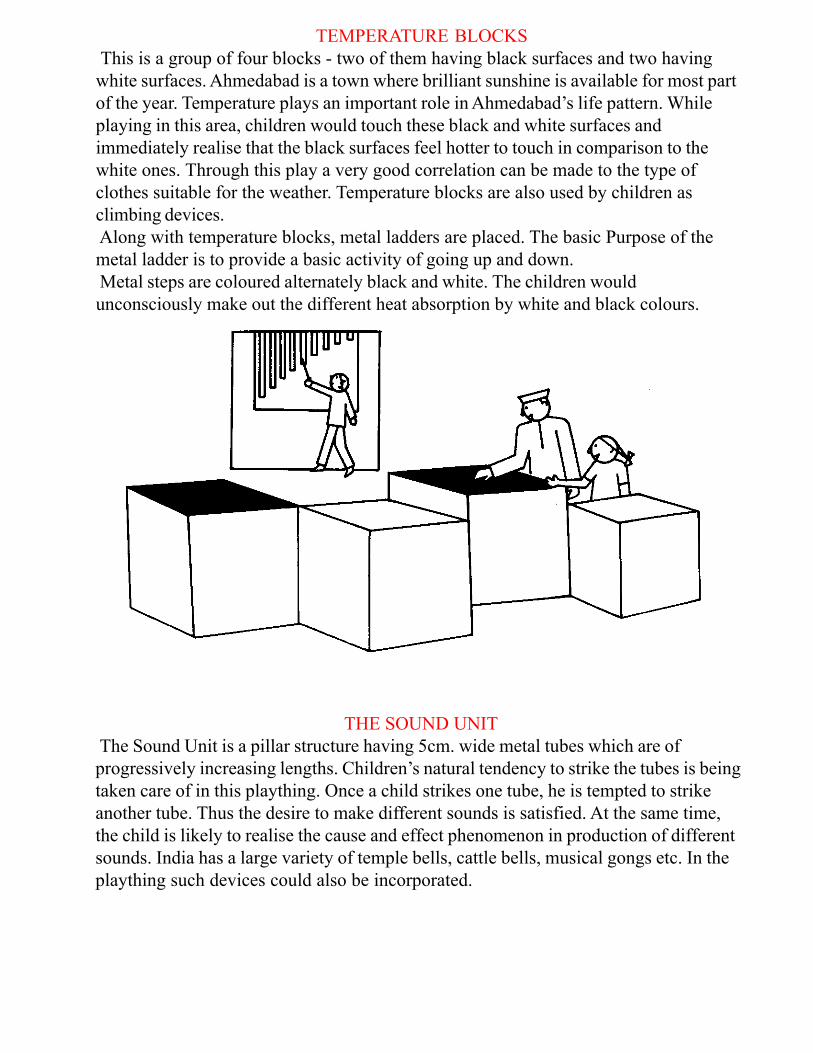
TEMPERATURE BLOCKS
This is a group of four blocks - two of them having black surfaces and two having
white surfaces. Ahmedabad is a town where brilliant sunshine is available for most part
of the year. Temperature plays an important role in Ahmedabad’s life pattern. While
playing in this area, children would touch these black and white surfaces and
immediately realise that the black surfaces feel hotter to touch in comparison to the
white ones. Through this play a very good correlation can be made to the type of
clothes suitable for the weather. Temperature blocks are also used by children as
climbing devices.
Along with temperature blocks, metal ladders are placed. The basic Purpose of the
metal ladder is to provide a basic activity of going up and down.
Metal steps are coloured alternately black and white. The children would
unconsciously make out the different heat absorption by white and black colours.
THE SOUND UNIT
The Sound Unit is a pillar structure having 5cm. wide metal tubes which are of
progressively increasing lengths. Children’s natural tendency to strike the tubes is being
taken care of in this plaything. Once a child strikes one tube, he is tempted to strike
another tube. Thus the desire to make different sounds is satisfied. At the same time,
the child is likely to realise the cause and effect phenomenon in production of different
sounds. India has a large variety of temple bells, cattle bells, musical gongs etc. In the
plaything such devices could also be incorporated.
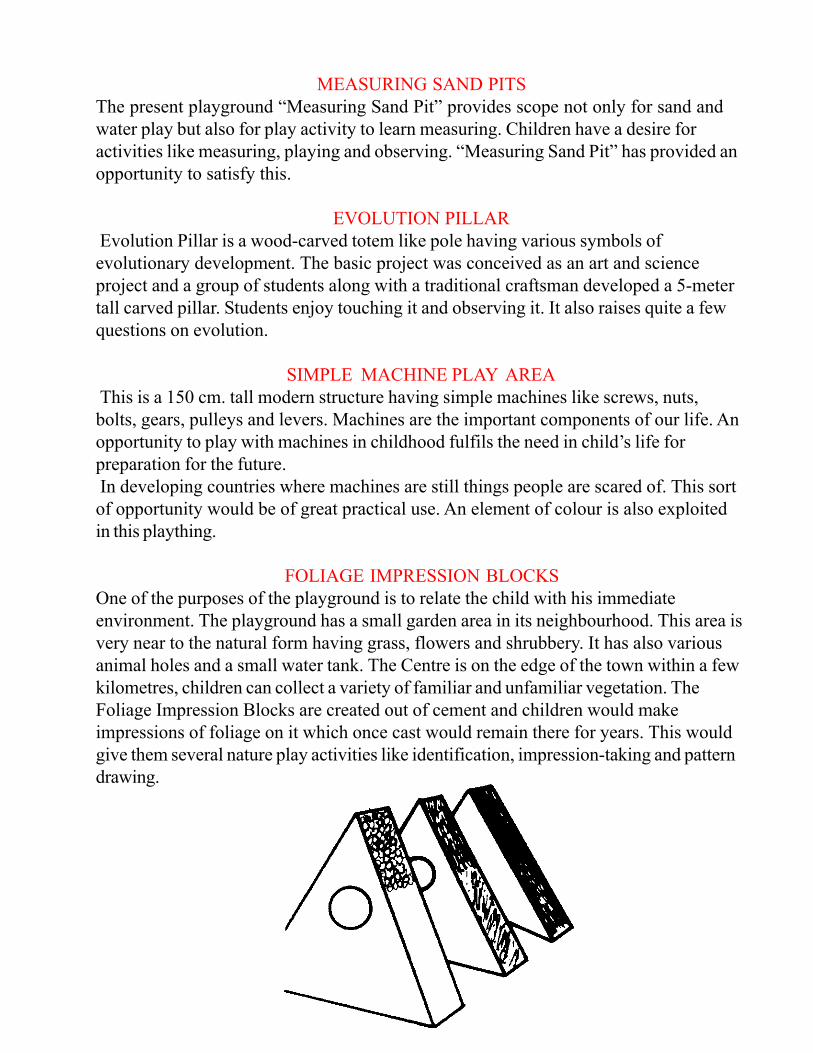
MEASURING SAND PITS
The present playground “Measuring Sand Pit” provides scope not only for sand and
water play but also for play activity to learn measuring. Children have a desire for
activities like measuring, playing and observing. “Measuring Sand Pit” has provided an
opportunity to satisfy this.
EVOLUTION PILLAR
Evolution Pillar is a wood-carved totem like pole having various symbols of
evolutionary development. The basic project was conceived as an art and science
project and a group of students along with a traditional craftsman developed a 5-meter
tall carved pillar. Students enjoy touching it and observing it. It also raises quite a few
questions on evolution.
SIMPLE MACHINE PLAY AREA
This is a 150 cm. tall modern structure having simple machines like screws, nuts,
bolts, gears, pulleys and levers. Machines are the important components of our life. An
opportunity to play with machines in childhood fulfils the need in child’s life for
preparation for the future.
In developing countries where machines are still things people are scared of. This sort
of opportunity would be of great practical use. An element of colour is also exploited
in this plaything.
FOLIAGE IMPRESSION BLOCKS
One of the purposes of the playground is to relate the child with his immediate
environment. The playground has a small garden area in its neighbourhood. This area is
very near to the natural form having grass, flowers and shrubbery. It has also various
animal holes and a small water tank. The Centre is on the edge of the town within a few
kilometres, children can collect a variety of familiar and unfamiliar vegetation. The
Foliage Impression Blocks are created out of cement and children would make
impressions of foliage on it which once cast would remain there for years. This would
give them several nature play activities like identification, impression-taking and pattern
drawing.
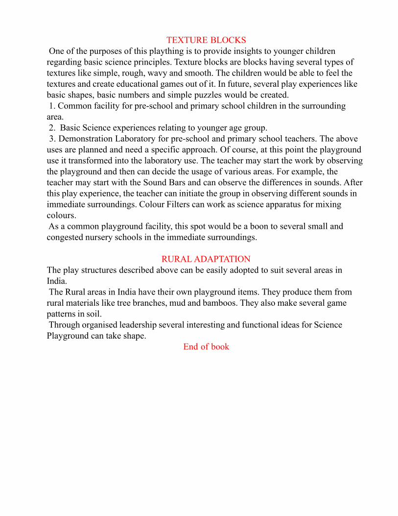
TEXTURE BLOCKS
One of the purposes of this plaything is to provide insights to younger children
regarding basic science principles. Texture blocks are blocks having several types of
textures like simple, rough, wavy and smooth. The children would be able to feel the
textures and create educational games out of it. In future, several play experiences like
basic shapes, basic numbers and simple puzzles would be created.
1. Common facility for pre-school and primary school children in the surrounding
area.
2. Basic Science experiences relating to younger age group.
3. Demonstration Laboratory for pre-school and primary school teachers. The above
uses are planned and need a specific approach. Of course, at this point the playground
use it transformed into the laboratory use. The teacher may start the work by observing
the playground and then can decide the usage of various areas. For example, the
teacher may start with the Sound Bars and can observe the differences in sounds. After
this play experience, the teacher can initiate the group in observing different sounds in
immediate surroundings. Colour Filters can work as science apparatus for mixing
colours.
As a common playground facility, this spot would be a boon to several small and
congested nursery schools in the immediate surroundings.
RURAL ADAPTATION
The play structures described above can be easily adopted to suit several areas in
India.
The Rural areas in India have their own playground items. They produce them from
rural materials like tree branches, mud and bamboos. They also make several game
patterns in soil.
Through organised leadership several interesting and functional ideas for Science
Playground can take shape.
End of book