Embed Size (px)
Citation preview
BMW Service Aftersales Training
Participant's ManualSuspension E90
The information contained in this Participant's Manual is intended solely for the participants ofthis seminar run by BMW Aftersales Training.
Refer to the latest relevant "BMW Service" information for any changes/supplements to theTechnical Data.
Information status: October 2004
© 2004 BMW GroupAftersales Training, München, Germany.Reprints of this manual or its parts require the written approval of BMW Group,München.
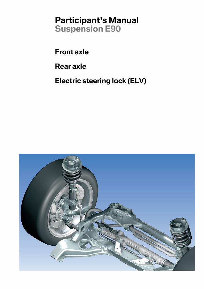
Participant's ManualSuspension E90
Front axle
Rear axle
Electric steering lock (ELV)
Information on this Participant's Manual
Symbols used
The following symbols are used in this Participant's Manual to facilitatebetter comprehension and to draw attention to important information.
3 contains information for better understanding of the describedsystems and their functions.
1 identifies the end of an item of information.
Current content of Participant's Manual
In view of the constant further developments in the design and equipmentof BMW vehicles deviations may arise between this Participant's Manualand the vehicles made available as part of the training course.
The background material refers exclusively to left-hand drive vehicles.The controls are in part arranged differently in right-hand drive vehiclesthan shown on the graphics in the Participant's Manual.
Additional information sources
You will find further information on the individual vehicle topic in the BMWdiagnosis and repair systems as well as on the Internet underwww.bmw.com.
ContentsSuspension E90
Objectives 1
Purpose of this Participant's Manual 1
Models 3
Development of BMW rear axles 3
Introduction 5
System components 7
E90 front axle 7E90 rear axle 11Electric steering lock 19
Service information 27

5
ObjectivesSuspension E90
Purpose of this Participant's Manual
The Participant's Manual is a documentdesigned to accompany a seminar while at thesame time serving as a source of reference.
The front and rear axles and the electricsteering lock (ELV) are described in thisParticipant's Manual.
1

5
2
6
ModelsSuspension E90
Development of BMW rear axles
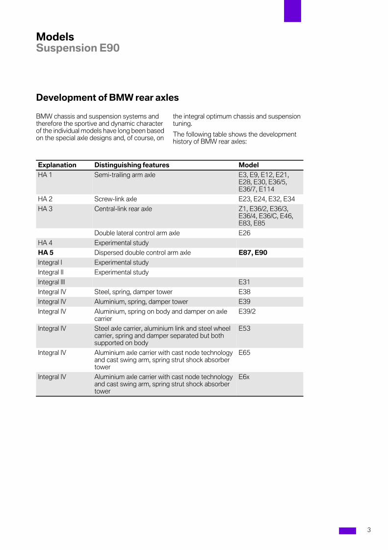
BMW chassis and suspension systems andtherefore the sportive and dynamic characterof the individual models have long been basedon the special axle designs and, of course, on
the integral optimum chassis and suspensiontuning.
The following table shows the developmenthistory of BMW rear axles:
Explanation Distinguishing features Model
HA 1 Semi-trailing arm axle E3, E9, E12, E21,E28, E30, E36/5,E36/7, E114
HA 2 Screw-link axle E23, E24, E32, E34
HA 3 Central-link rear axle Z1, E36/2, E36/3,E36/4, E36/C, E46,E83, E85
Double lateral control arm axle E26
HA 4 Experimental study
HA 5 Dispersed double control arm axle E87, E90
Integral I Experimental study
Integral II Experimental study
Integral III E31
Integral IV Steel, spring, damper tower E38
Integral IV Aluminium, spring, damper tower E39
Integral IV Aluminium, spring on body and damper on axlecarrier
E39/2
Integral IV Steel axle carrier, aluminium link and steel wheelcarrier, spring and damper separated but bothsupported on body
E53
Integral IV Aluminium axle carrier with cast node technologyand cast swing arm, spring strut shock absorbertower
E65
Integral IV Aluminium axle carrier with cast node technologyand cast swing arm, spring strut shock absorbertower
E6x
3

6
4
7
IntroductionSuspension E90
Suspension E90
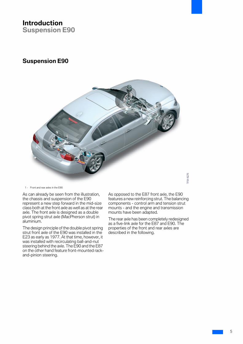
As can already be seen from the illustration,the chassis and suspension of the E90represent a new step forward in the mid-sizeclass both at the front axle as well as at the rearaxle. The front axle is designed as a doublepivot spring strut axle (MacPherson strut) inaluminium.
The design principle of the double pivot springstrut front axle of the E90 was installed in theE23 as early as 1977. At that time, however, itwas installed with recirculating ball-and-nutsteering behind the axle. The E90 and the E87on the other hand feature front-mounted rack-and-pinion steering.
As opposed to the E87 front axle, the E90features a new reinforcing strut. The balancingcomponents - control arm and tension strutmounts - and the engine and transmissionmounts have been adapted.
The rear axle has been completely redesignedas a five-link axle for the E87 and E90. Theproperties of the front and rear axles aredescribed in the following.
1 - Front and rear axles in the E90
5

7
6
8
System componentsSuspension E90
E90 front axle
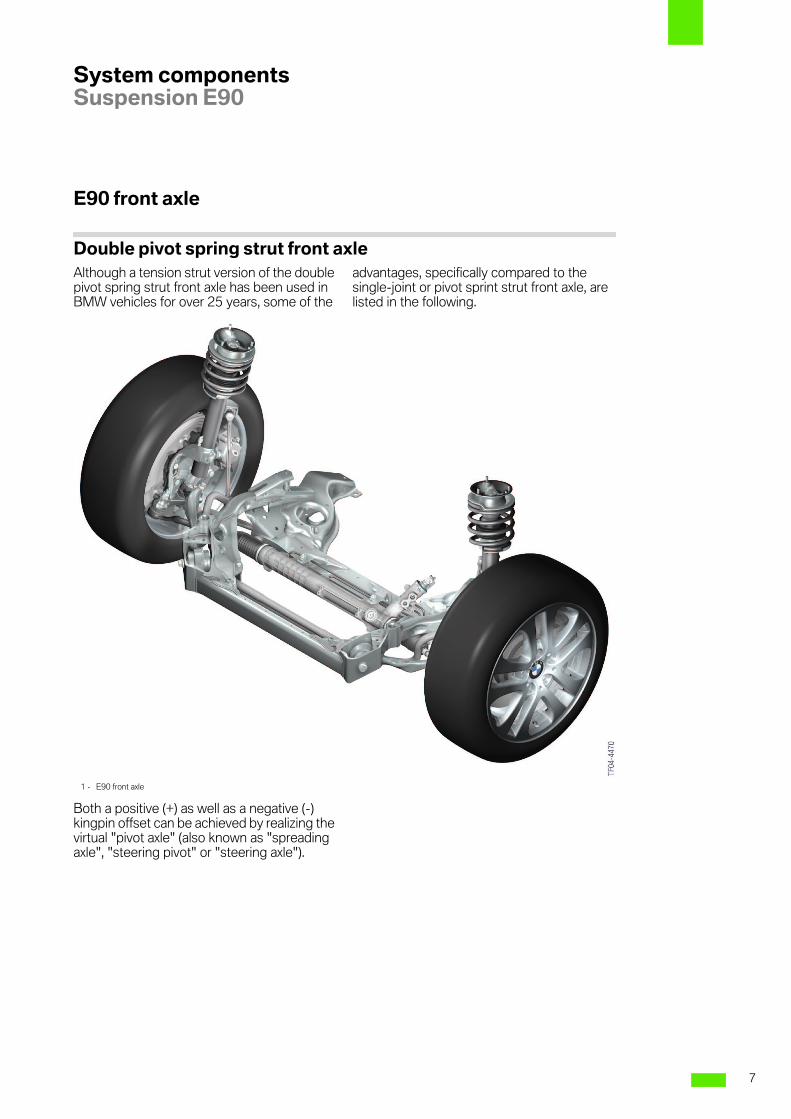
Double pivot spring strut front axleAlthough a tension strut version of the doublepivot spring strut front axle has been used inBMW vehicles for over 25 years, some of the
advantages, specifically compared to thesingle-joint or pivot sprint strut front axle, arelisted in the following.
Both a positive (+) as well as a negative (-)kingpin offset can be achieved by realizing thevirtual "pivot axle" (also known as "spreadingaxle", "steering pivot" or "steering axle").
1 - E90 front axle
7
8
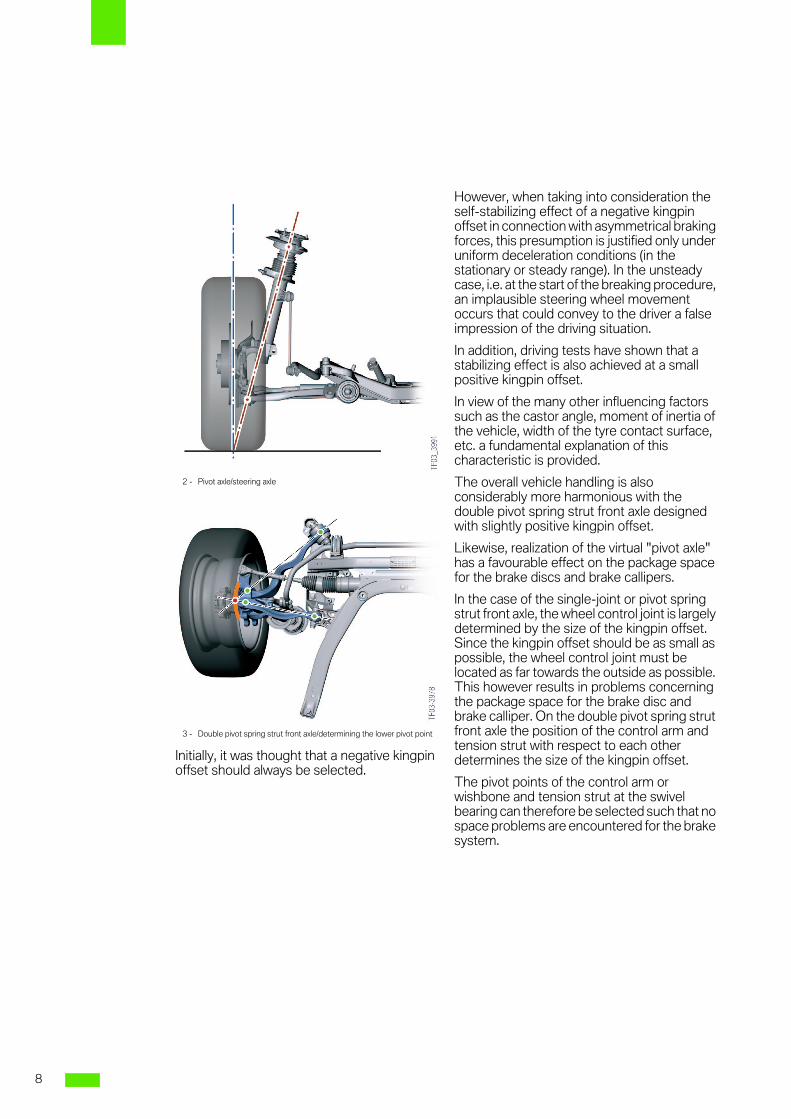
Initially, it was thought that a negative kingpinoffset should always be selected.
However, when taking into consideration theself-stabilizing effect of a negative kingpinoffset in connection with asymmetrical brakingforces, this presumption is justified only underuniform deceleration conditions (in thestationary or steady range). In the unsteadycase, i.e. at the start of the breaking procedure,an implausible steering wheel movementoccurs that could convey to the driver a falseimpression of the driving situation.
In addition, driving tests have shown that astabilizing effect is also achieved at a smallpositive kingpin offset.
In view of the many other influencing factorssuch as the castor angle, moment of inertia ofthe vehicle, width of the tyre contact surface,etc. a fundamental explanation of thischaracteristic is provided.
The overall vehicle handling is alsoconsiderably more harmonious with thedouble pivot spring strut front axle designedwith slightly positive kingpin offset.
Likewise, realization of the virtual "pivot axle"has a favourable effect on the package spacefor the brake discs and brake callipers.
In the case of the single-joint or pivot springstrut front axle, the wheel control joint is largelydetermined by the size of the kingpin offset.Since the kingpin offset should be as small aspossible, the wheel control joint must belocated as far towards the outside as possible.This however results in problems concerningthe package space for the brake disc andbrake calliper. On the double pivot spring strutfront axle the position of the control arm andtension strut with respect to each otherdetermines the size of the kingpin offset.
The pivot points of the control arm orwishbone and tension strut at the swivelbearing can therefore be selected such that nospace problems are encountered for the brakesystem.
2 - Pivot axle/steering axle
3 - Double pivot spring strut front axle/determining the lower pivot point
8
8
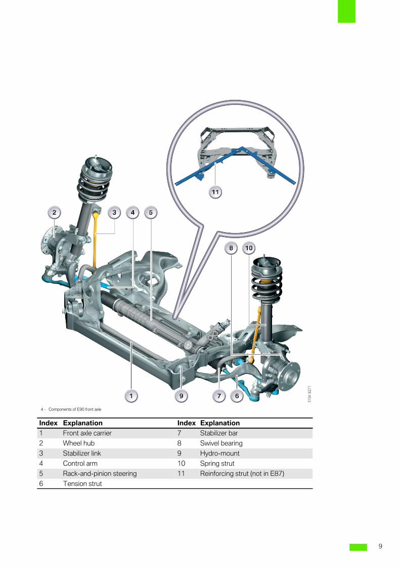
4 - Components of E90 front axle
Index Explanation Index Explanation
1 Front axle carrier 7 Stabilizer bar
2 Wheel hub 8 Swivel bearing
3 Stabilizer link 9 Hydro-mount
4 Control arm 10 Spring strut
5 Rack-and-pinion steering 11 Reinforcing strut (not in E87)
6 Tension strut
9
8
Both tension struts are mounted withhydraulic mounts in the front axle carrier.
In addition, the distance of the tension strutand control arm pivot points at the swivelbearing largely determines the vertical forcelever arm.
The greater the joints of the tension strut andcontrol arm are from each other at the swivelbearing, the greater the weight reset force.
On the single-joint sprint strut front axle, thedistance is generally zero as the two joints ofthis axle have, as it were, merged to form one.The resulting advantage of the double pivot orjoint spring strut front axle is improveddirectional stability in the high speed rangeand a lower tendency to steering instability inthe lower speed range (insignificant forsteering wheel torsional vibration LDS).
Compared to that of the control arm, the balljoint (guide joint) of the tension strut is raisedat the swivel bearing, thus providing effectiveanti-dive control. A further advantage of thisarrangement is that this tension strut mounton the axle carrier can be arranged atapproximately the same level with respect tothe mounting at the swivel bearing and doesnot have to be lowered. This is of particularbenefit to a large overhang angle. In addition,it is possible to lower the control arm mount onthe axle carrier side, thus enabling a lower rollcentre.
The single-joint spring strut front axle featuresonly one type of cross brace as the axle carrier.
The double pivot spring strut front axle on theother hand features a frame which additionallyprovides significant stiffening of the front end.
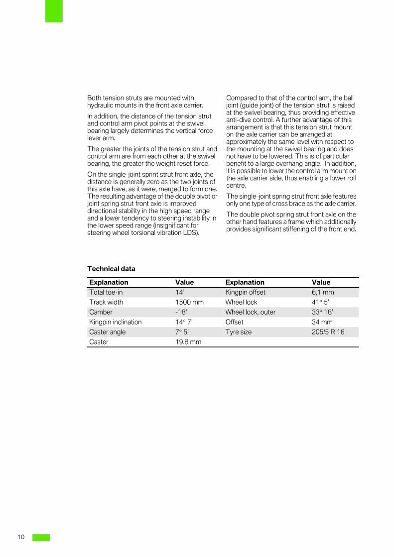
Technical data
Explanation Value Explanation Value
Total toe-in 14’ Kingpin offset 6,1 mm
Track width 1500 mm Wheel lock 41° 5’
Camber -18’ Wheel lock, outer 33° 18’
Kingpin inclination 14° 7’ Offset 34 mm
Caster angle 7° 5’ Tyre size 205/5 R 16
Caster 19.8 mm
10
8
E90 rear axle
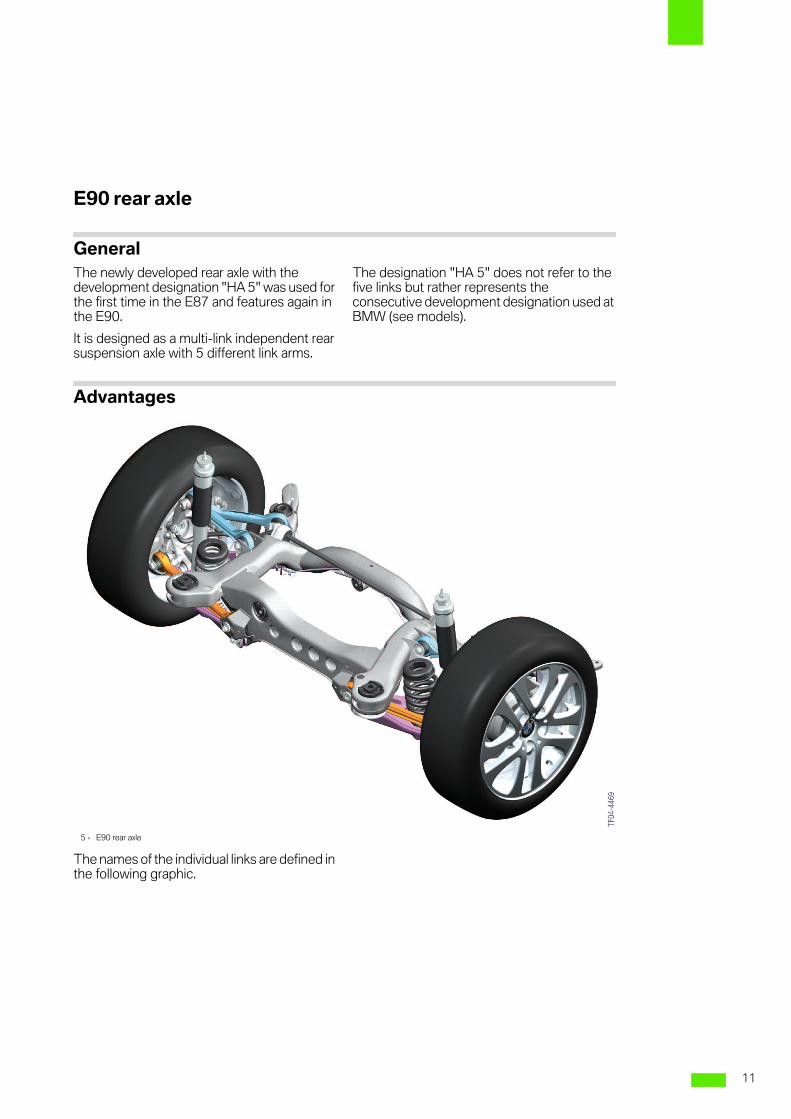
GeneralThe newly developed rear axle with thedevelopment designation "HA 5" was used forthe first time in the E87 and features again inthe E90.
It is designed as a multi-link independent rearsuspension axle with 5 different link arms.
The designation "HA 5" does not refer to thefive links but rather represents theconsecutive development designation used atBMW (see models).
Advantages
The names of the individual links are defined inthe following graphic.
5 - E90 rear axle
11
8
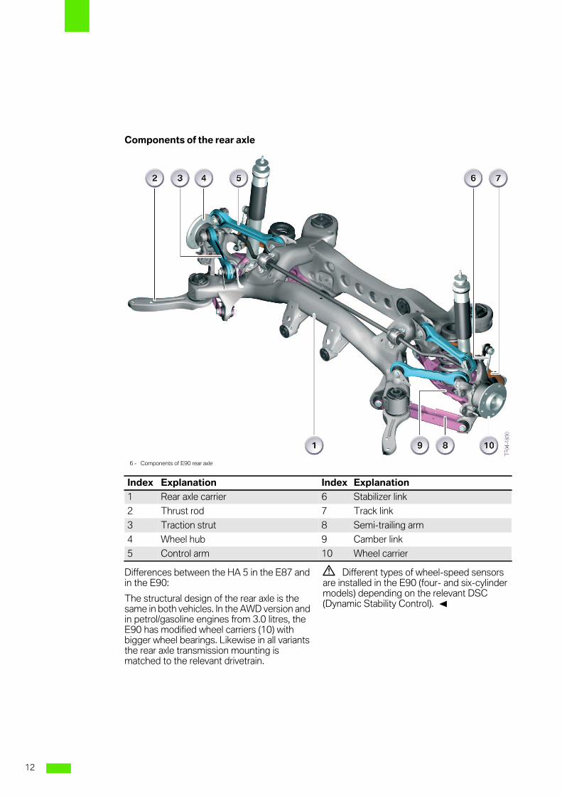
Components of the rear axle
Differences between the HA 5 in the E87 andin the E90:
The structural design of the rear axle is thesame in both vehicles. In the AWD version andin petrol/gasoline engines from 3.0 litres, theE90 has modified wheel carriers (10) withbigger wheel bearings. Likewise in all variantsthe rear axle transmission mounting ismatched to the relevant drivetrain.
3 Different types of wheel-speed sensorsare installed in the E90 (four- and six-cylindermodels) depending on the relevant DSC(Dynamic Stability Control). 1
6 - Components of E90 rear axle
Index Explanation Index Explanation
1 Rear axle carrier 6 Stabilizer link
2 Thrust rod 7 Track link
3 Traction strut 8 Semi-trailing arm
4 Wheel hub 9 Camber link
5 Control arm 10 Wheel carrier
12
8
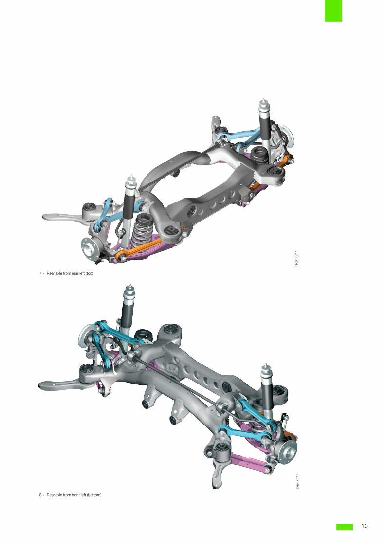
7 - Rear axle from rear left (top)
8 - Rear axle from front left (bottom)
13
8
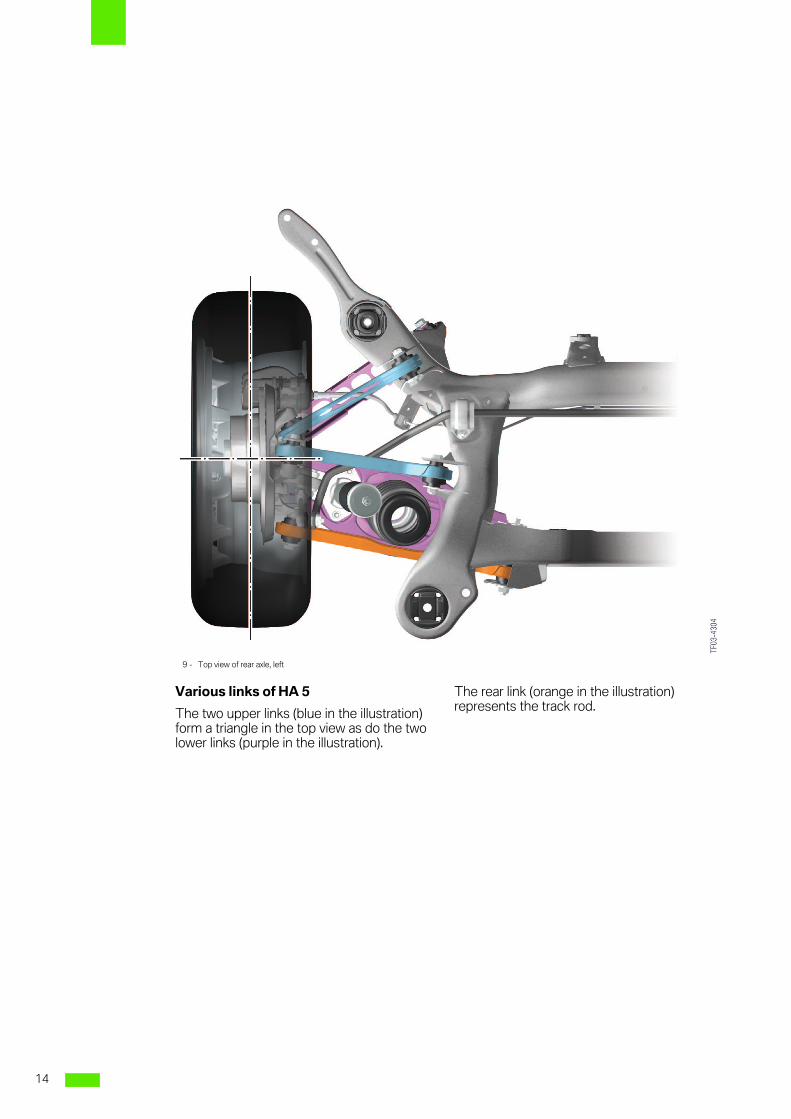
Various links of HA 5
The two upper links (blue in the illustration)form a triangle in the top view as do the twolower links (purple in the illustration).
The rear link (orange in the illustration)represents the track rod.
9 - Top view of rear axle, left
14
8
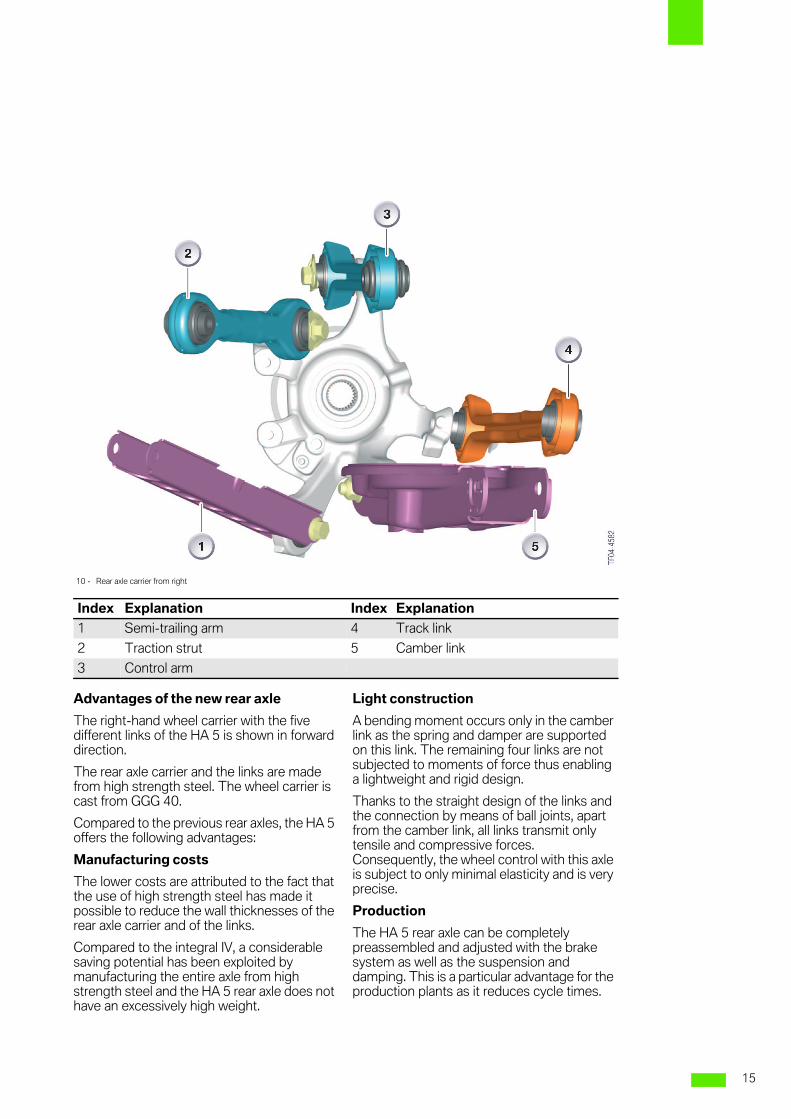
Advantages of the new rear axle
The right-hand wheel carrier with the fivedifferent links of the HA 5 is shown in forwarddirection.
The rear axle carrier and the links are madefrom high strength steel. The wheel carrier iscast from GGG 40.
Compared to the previous rear axles, the HA 5offers the following advantages:
Manufacturing costs
The lower costs are attributed to the fact thatthe use of high strength steel has made itpossible to reduce the wall thicknesses of therear axle carrier and of the links.
Compared to the integral IV, a considerablesaving potential has been exploited bymanufacturing the entire axle from highstrength steel and the HA 5 rear axle does nothave an excessively high weight.
Light construction
A bending moment occurs only in the camberlink as the spring and damper are supportedon this link. The remaining four links are notsubjected to moments of force thus enablinga lightweight and rigid design.
Thanks to the straight design of the links andthe connection by means of ball joints, apartfrom the camber link, all links transmit onlytensile and compressive forces.Consequently, the wheel control with this axleis subject to only minimal elasticity and is veryprecise.
Production
The HA 5 rear axle can be completelypreassembled and adjusted with the brakesystem as well as the suspension anddamping. This is a particular advantage for theproduction plants as it reduces cycle times.
10 - Rear axle carrier from right
Index Explanation Index Explanation
1 Semi-trailing arm 4 Track link
2 Traction strut 5 Camber link
3 Control arm
15
8
Kinematics
The very small positive kingpin offsetguarantees insensitivity to longitudinal forceseven in connection with wide tyres.
The relatively large caster ensures a defineddegree of lateral force understeering andtherefore obliging vehicle handling. Thismethod of vehicle stabilization offers thefastest response and is therefore also thebest.
The change in toe as part of the suspensionaction enables outstanding directional stabilitywith a relatively short wheelbase andexceptional self-steering characteristics whilecornering.
The change in camber as part of thesuspension action is selected such that anoptimum camber with respect to the roadsurface is always established while cornering.Nevertheless, the change in camber duringspring compression due to load is not toogreat as to cause increased tyre wear. As aresult, new lateral force potentials are utilizedtogether with RSC tyres (tyres with runflatproperties).
The long design of the track link makes foroutstanding length tolerance insensitivity. Thelong track link also has a positive effect on thetoe-in characteristics over the spring travelrange.
The low roll centre has a particularly beneficialeffect on the rolling motion.
The "propping" effect while cornering hasbeen largely minimized by improving the rollcentre change rate.
The braking support has been set to 70 %.Racing cars generally have a support angle of0 % in order to constantly achieve maximumcontact force. On these vehicles, thedisadvantage of a dive motion while brakingand starting off is compensated by the tautsuspension. The braking support (anti-dive)realized on the E87 and E90 represents anoptimum compromise between comfort,safety and driving dynamics requirements.
The use of five links enables free selection ofthe pivot axle for the design layout. Thismeans that the movement of the wheel ininteraction with the suspension can beoptimized without compromise under braking,acceleration and lateral forces. This largelydetermines all important variables such as toe,camber, brake support (anti-dive) angle, rollcentre and roll centre change rate.
16
8
Crash requirements
The frame side member had to be cranked toa relatively large extent in connection with thesemi-trailing arm and central-link rear axle.This brought about disadvantages inconnection with a rear end impact. In contract,the HA 5 rear axle permits a considerably morefavourable progression of the side member,
resulting in specific advantages particularly atlow impact speeds.
Added to this, the large rear axle carrier isconnected directly to the rigid frame sidemember, allowing it to transmit the appliedcrash forces more favourably. The semi-trailing arm features crash beading (in thesemi-trailing arm of the HA 5 rear axle, see Fig.6) to ensure the fuel tank is not damaged.
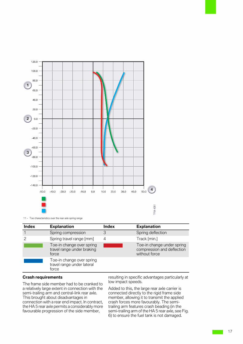
11 - Toe characteristics over the rear axle spring range
Index Explanation Index Explanation
1 Spring compression 3 Spring deflection
2 Spring travel range [mm] 4 Track [min.]
Toe-in change over springtravel range under brakingforce
Toe-in change under springcompression and deflectionwithout force
Toe-in change over springtravel range under lateralforce
17
8
Rigidity/acoustics
The rear axle carrier of the HA 5 rear axleextends up to the rigid frame side members ofthe body with its axle mounting points andeven up to the sill with its thrust rods. Thisprovides a very large support face for theapplied forces and moments. The resultingadvantages include, on the one hand,considerably lower stress and strain on thebody (rear axle break-away) and, on the otherhand, the option of designing the rear axlebearing mounts, which are wide apart,relatively soft. This arrangement and thedouble flexible mounting provide outstanding
insulation against road noise and tyre rollingnoise.
Technical data (standard suspension,7Jx16)
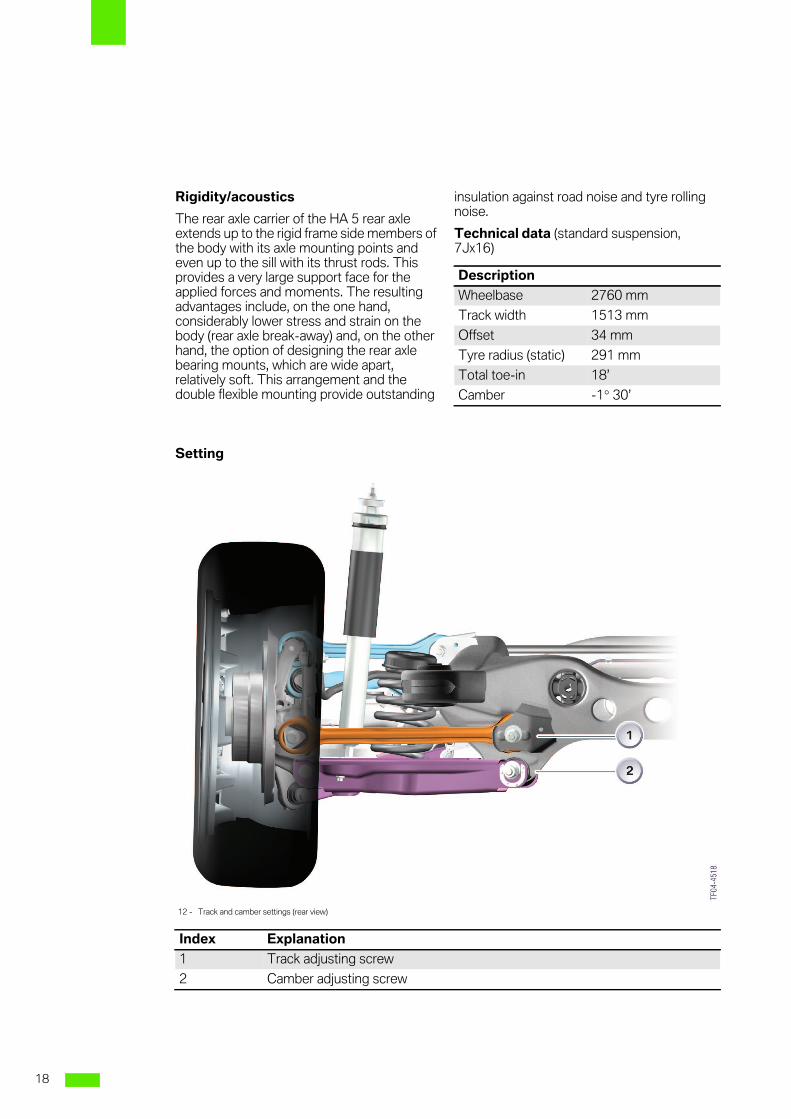
Setting
Description
Wheelbase 2760 mm
Track width 1513 mm
Offset 34 mm
Tyre radius (static) 291 mm
Total toe-in 18’
Camber -1° 30’
12 - Track and camber settings (rear view)
Index Explanation
1 Track adjusting screw
2 Camber adjusting screw
18
8
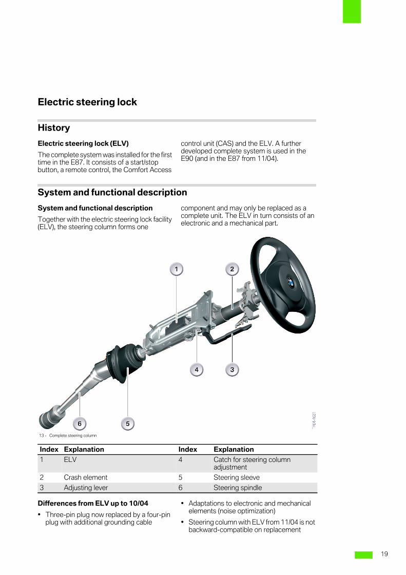
Electric steering lock
History
Electric steering lock (ELV)
The complete system was installed for the firsttime in the E87. It consists of a start/stopbutton, a remote control, the Comfort Access
control unit (CAS) and the ELV. A furtherdeveloped complete system is used in theE90 (and in the E87 from 11/04).
System and functional description
System and functional description
Together with the electric steering lock facility(ELV), the steering column forms one
component and may only be replaced as acomplete unit. The ELV in turn consists of anelectronic and a mechanical part.
Differences from ELV up to 10/04
• Three-pin plug now replaced by a four-pinplug with additional grounding cable
• Adaptations to electronic and mechanicalelements (noise optimization)
• Steering column with ELV from 11/04 is notbackward-compatible on replacement
13 - Complete steering column
Index Explanation Index Explanation
1 ELV 4 Catch for steering columnadjustment
2 Crash element 5 Steering sleeve
3 Adjusting lever 6 Steering spindle
19
8
Electronic part of the ELV
2x ground and a 12 volt voltage are applied tothe four-pin plug connection. A K-bus linefrom the CAS delivers the necessarycommunication signal to the ELV.
The CAS monitors the various driving orstandstill situations of the vehicle (signal fromDSC) and is therefore also the control unit thattriggers the unlocking (release) or lockingaction in the ELV. It also switches the groundand 12 V cable for locking and only the 12 Vcable for unlocking (therefore new groundcable). Generally, no power is applied to theELV when the vehicle is not stationary.
Mechanical part of the ELV
A locking lever with its position monitored by asensor and a locking pin are the maincomponents of the mechanical part designedto lock or unlock the steering column at thecorrect moment. The entire internal kinematicstructure is designed such that a mechanicallock (locking lever) keeps the unlocked lockingpin in position when no power is applied to theELV.
Advantages of the ELV:
• Remote control as on the E65 in the form ofa "bitless" key
• High 2-fault security (an electronic fault anda mechanical fault must occursimultaneously) in accordance with DINStandard SIL3
• No steering wheel lock in knee impact area.
• The E90 can also be equipped with theComfort Access option.
The E46 featured an infinitely variable clampconnection for the steering wheel up/downand in/out adjustment. An extremely closely-stepped catch connection is used in the E90as in the E87.
The adjustment range has been extended andthe user friendliness increased. The newadjustment unit now supports the airbag andthe steering column. The upper area of thesteering column and an integrated crashelement (metal tube) are designed as load-bearing parts.
The metal tube is pre-perforated in a definedlongitudinal area at the upper end of thesteering column. In the event of an impact, thismetal tube begins to crack at the predefinedpoints. This perforation is required for thepurpose of converting energy in the event ofan impact.
The steering column must always be replacedafter an airbag has triggered or the steeringshaft is replaced!
The steering spindle sleeve or collar is alsonew (as in the E87). On the E46, this collar washeld in position by the pedal assembly. Thenew collar is connected in the bulkhead and isdouble-sided. This arrangement results in alower reset force for the steering columnheight adjustment.
20
8
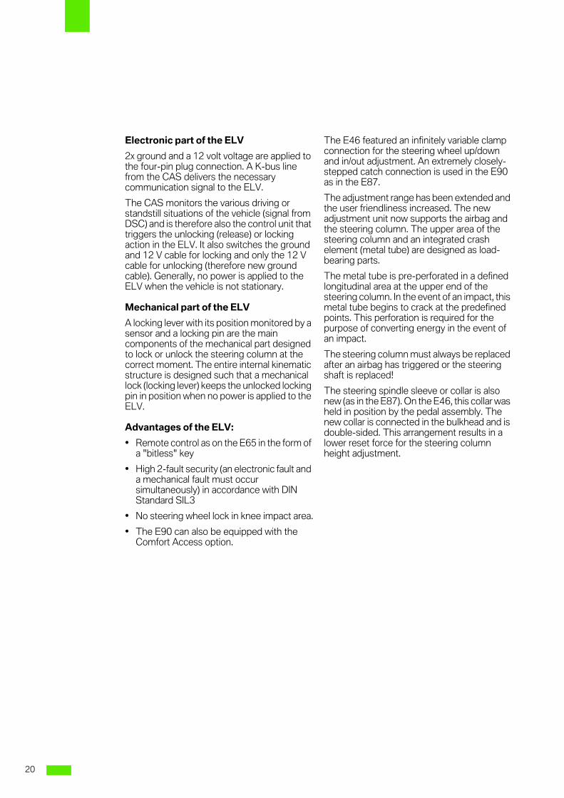
In the following, the ELV is shown without theelectronics and only the mechanism isexplained.
14 - ELV assy without cover (opened)
21
8
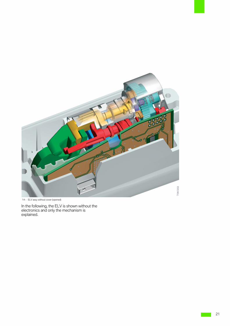
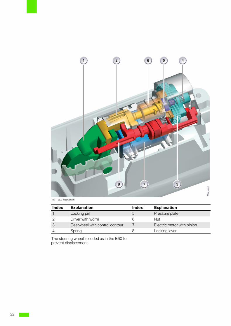
The steering wheel is coded as in the E60 toprevent displacement.
15 - ELV mechanism
Index Explanation Index Explanation
1 Locking pin 5 Pressure plate
2 Driver with worm 6 Nut
3 Gearwheel with control contour 7 Electric motor with pinion
4 Spring 8 Locking lever
22
8
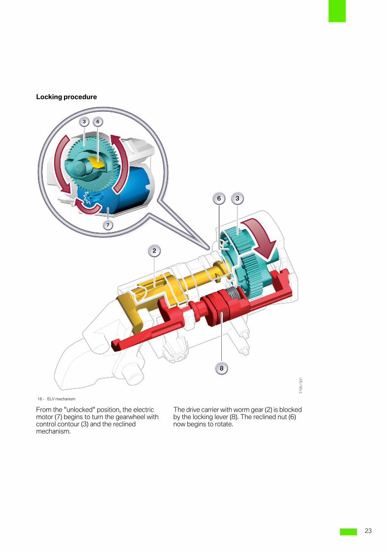
Locking procedure
From the "unlocked" position, the electricmotor (7) begins to turn the gearwheel withcontrol contour (3) and the reclinedmechanism.
The drive carrier with worm gear (2) is blockedby the locking lever (8). The reclined nut (6)now begins to rotate.
16 - ELV mechanism
23
8
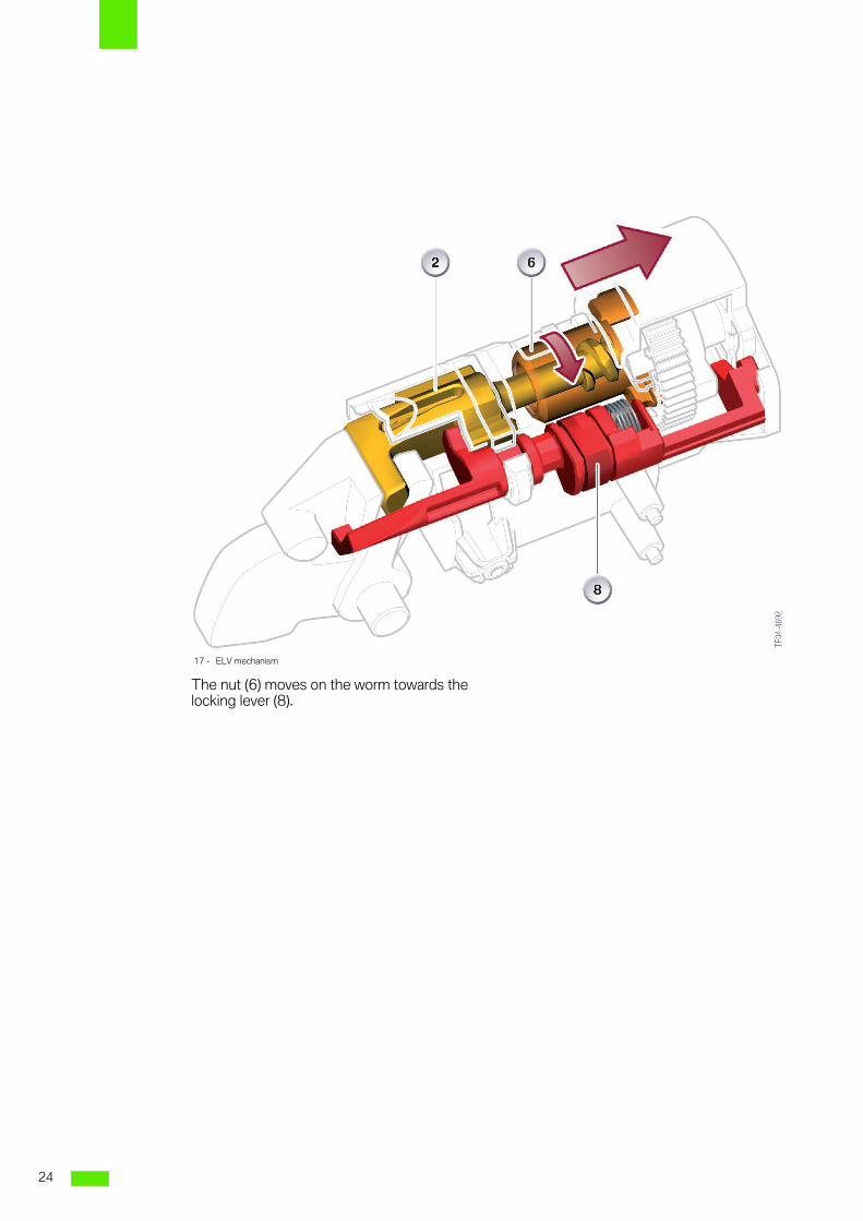
The nut (6) moves on the worm towards thelocking lever (8).
17 - ELV mechanism
24
8
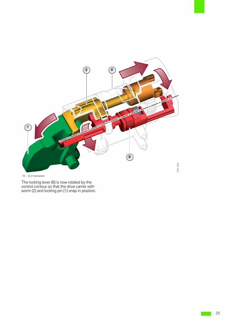
The locking lever (8) is now rotated by thecontrol contour so that the drive carrier withworm (2) and locking pin (1) snap in position.
18 - ELV mechanism
25
8
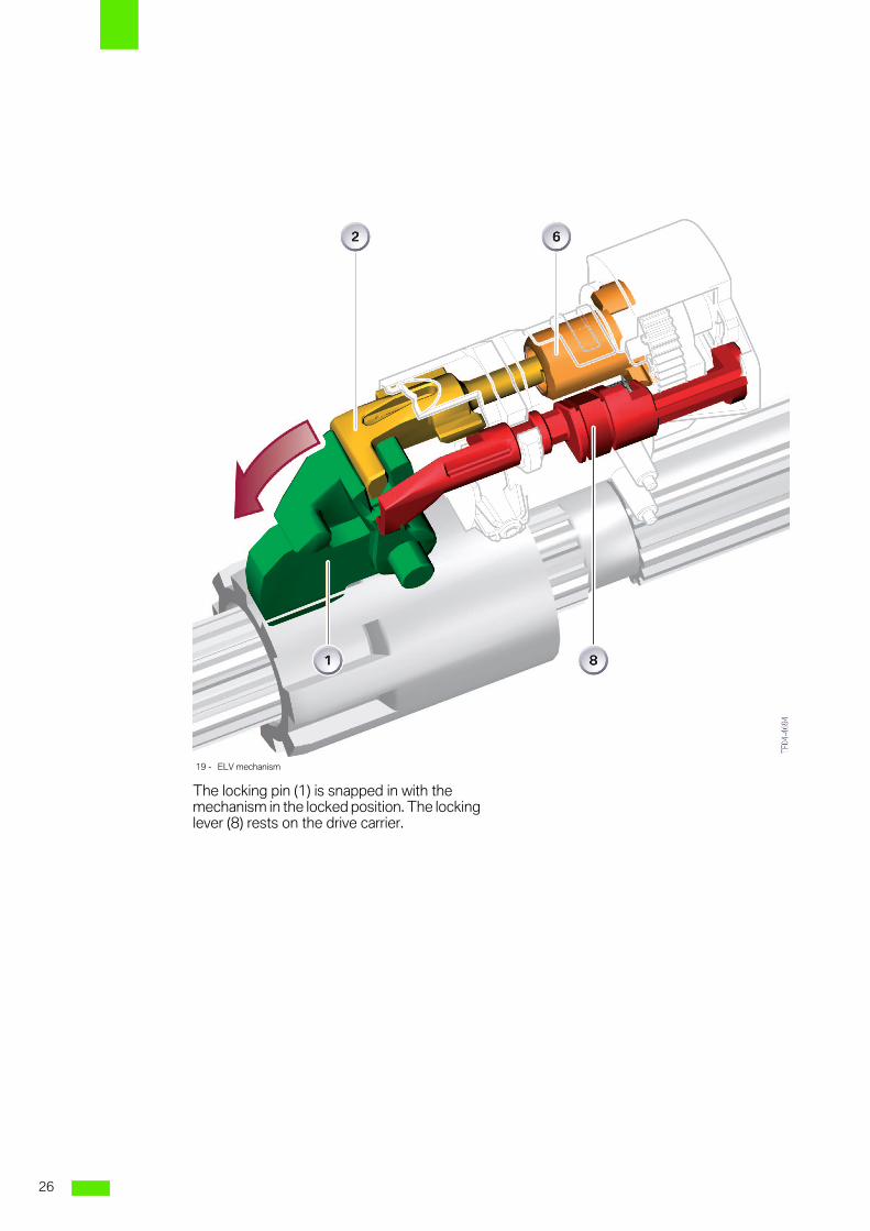
The locking pin (1) is snapped in with themechanism in the locked position. The lockinglever (8) rests on the drive carrier.
19 - ELV mechanism
26
9
Service informationSuspension E90
Summary
Electric steering lock3 Together with the electric steering lockfacility (ELV), the steering column forms onecomponent and may only be replaced as acomplete unit.
The steering column with ELV from 11/04 isnot backward-compatible on replacement. 1
27

9
28

Abbreviations
CAS Car access system
DSC Dynamic stability control
ELV Electric steering lock
LDS Steering wheel torsional vibration


Dieser Text muss hier stehen, damit die Seite vom API-Client nicht gelöscht wird.Dieser Text ist notwendig, damit die Seite nicht quergestellt wird.!

BMW ServiceAftersales Training
80788 München
Fax. +49 89 382-34450
: