Embed Size (px)
Citation preview
CATHODIC PROTECTION\PARTIAL COATINGS
VERSUS
COMPLETE COATING in BALLAST TANKS-FIVE YEAR REPORT
NOVEMBER 1987
Prepared byAssociated Coating Consultants
Galveston, Texas 77554in Cooperation with
National Steel and Shipbuilding CompanySan Diego, California 92138
Report Documentation Page Form ApprovedOMB No. 0704-0188
Public reporting burden for the collection of information is estimated to average 1 hour per response, including the time for reviewing instructions, searching existing data sources, gathering andmaintaining the data needed, and completing and reviewing the collection of information. Send comments regarding this burden estimate or any other aspect of this collection of information,including suggestions for reducing this burden, to Washington Headquarters Services, Directorate for Information Operations and Reports, 1215 Jefferson Davis Highway, Suite 1204, ArlingtonVA 22202-4302. Respondents should be aware that notwithstanding any other provision of law, no person shall be subject to a penalty for failing to comply with a collection of information if itdoes not display a currently valid OMB control number.
1. REPORT DATE NOV 1987
2. REPORT TYPE N/A
3. DATES COVERED -
4. TITLE AND SUBTITLE Cathodic Protection/Partial Coatings Versus Complete Coating in BallastTanks-Five Year Report
5a. CONTRACT NUMBER
5b. GRANT NUMBER
5c. PROGRAM ELEMENT NUMBER
6. AUTHOR(S) 5d. PROJECT NUMBER
5e. TASK NUMBER
5f. WORK UNIT NUMBER
7. PERFORMING ORGANIZATION NAME(S) AND ADDRESS(ES) Naval Surface Warfare Center CD Code 2230 - Design Integration ToolsBuilding 192 Room 128 9500 MacArthur Blvd Bethesda, MD 20817-5700
8. PERFORMING ORGANIZATIONREPORT NUMBER
9. SPONSORING/MONITORING AGENCY NAME(S) AND ADDRESS(ES) 10. SPONSOR/MONITOR’S ACRONYM(S)
11. SPONSOR/MONITOR’S REPORT NUMBER(S)
12. DISTRIBUTION/AVAILABILITY STATEMENT Approved for public release, distribution unlimited
13. SUPPLEMENTARY NOTES
14. ABSTRACT
15. SUBJECT TERMS
16. SECURITY CLASSIFICATION OF: 17. LIMITATION OF ABSTRACT
SAR
18. NUMBEROF PAGES
27
19a. NAME OFRESPONSIBLE PERSON
a. REPORT unclassified
b. ABSTRACT unclassified
c. THIS PAGE unclassified
Standard Form 298 (Rev. 8-98) Prescribed by ANSI Std Z39-18
DISCLAIMER
This report was prepared as an account of government-sponsoredwork.
Neither the United States, nor the Maritime Administration, nor any person
acting on behalf of the Maritime Administration (A) makes any warranty
or representation,expressed or implied, with respect to the accuracy,
completeness or usefulness of the information contained in this report/
manual, or that the use of any information, apparatus, method, or process
disclosed in this report may not infringe privately owned rights; or (B)
assumes any liabilities with respect to the use of or for damages resulting
from the use of any information, apparatus, method, or process disclosed
in the report. As used in the above, “persons acting on behalf of the
Maritime Administration” includes any employee, contractor, or subcontractor
to the contractor of the Maritime Administration to the extent that such
employee, contractor, or subcontractor to the contractor prepares, handles,
or distributes, or provides access to any information pursuant to his
employment or contract or subcontract to the contractor with the Maritime
Administration. ANY POSSIBLE IMPLIED WARRANTIES OF MERCHANTABILITYAND/OR
FITNESS FOR PURPOSE ARE SPECIFICALLY DISCLAIMED.
FOREWORD
This research project was performed under the National Shipbuil-ding Research Program. The project, as a part of this program, isa cooperative cost shared effort between the Maritime Administra-tion and National Steel and Shipbuilding Company. The development
work was accomplished by Associated Coatings Consultants undersubcontract to National Steel and Shipbuilding Company. The over-all objective of the program is improved productivity, andtherefore, reduced shipbuilding costs.
This study has been undertaken with this goal in mind, and hasfollowed closely the project outline approved by the Society ofNava1 Architects and Marine Engineers (SNAME) Ship ProductionCommittee.
Mr. James R. Ruecker of National Steel and Shipbuilding was theR&D Program Manager responsible for technical direction and pub-lication of the final report. Program definition and guidance wasprovided by the members of the SP-3 (Formerly 023-1) SurfacePreparation and Coatings Committee of SNAME. Special thanks isgiven to Mr John Peart for providing technical direction andeditorial assistance.
EXECUTIVE SUMMARY
Ship ballast tanks are one of the most costly items of new shipconstruction. In addition, ballast tanks are one of the mostsevere corrosion areas during ship operations. The SP-3 Panel ofSNAME recognized these problems and selected a research anddevelopment project to investigate alternate, cost effectivecorrosion control solutions. Four approaches were originallyselected for mock-up ballast tank testing and 20 year life cyclecost analysis. A new coating system was added after three years.
● Completely coated tanks with high performance coating● Partially coated tanks with cathodic protection● preconstruction primer with cathodic protection● Soft coatings with cathodic protection● Rust tolerant epoxy coatings(Added after three years)
The initial report* published in 1982 and the project updatereport published in 1985 demonstrated that, of the systems eval-uated, the inorganic zinc preconstruction primer with zinc anodecathodic protection was the best performer, least expensive init-ially and least expensive over the 20 year economic life of theship. After five years of testing, this system continues to bethe best performer. Partial coating with cathodic protection haveperformed as well as complete coating and are more cost effect-ive. Soft coatings with cathodic protection failed in the first90 days and was discontinued. The preconstruction primer withaluminum anodes failed after three years and was replaced by arust tolerant, one coat epoxy system which is showing good re-sults after two years of testing.
Certain prerequisites were also found to be necessary to assuresuccessful cathodic protection performance, e.g. tanks must be“pressed up” with salt water ballast.
In conclusion, this project continues to achieve all projectgoals. Identification has been made of ballast tank corrosionprotection approaches which are effective in mitigating corrosionand yet save both new construction and operating dollars. A finalreport, to include an updated economic analysis, is scheduled forpublication in early 1988.
*Benjamin S. Fultz, “cathodic Protection/Partial Coating versusComplete Coatings in Tanks,” May 1982, NSRP #0158, A MarAd Spon-sored Project.
3
TABLE OF CONTENTS
Foreword
Executive Summary
Table of Contents
List of Figures
List of Tables
1. Conclusions1.1 Project Results1.2 Continued Research
2. Project Plan of Action and Results2.1 Background Technical Information
2.1.1
2.1.2
2.1.3
2.2 Tank2.2.1
2.2.2
2.2.3
2.2.4
2.2.5
2.2.6
2.2.7
2.2.8
..- High Performance Coating SystemsPartial Coating of Tanks Combinedwith Cathodic ProtectionPreconstruction Primer PlusCathodic Protection
Test ResultsPerformance of Tank 1-Aluminum Anodes w/Partial CoatingsPerformance of Tank 2-Completely Coated TankPerformance of Tank 3-Zinc Anodes w/Partial CoatingsPerformance of Tank 4-Aluminum Anodes w/Preconstruction PrimerPerformance of Tank 5–Preconstruction Primer OnlyPerformance of Tank 6-Zinc Anode w/Preconstruction PrimerPerformance of Rust Tolerant EpoxyCoatings (Recoated Tank 5)Comparison of Ultrasonic Steel ThicknessReading
2.3 Anode Performance
PAGE2
3
4
5
6
778
9999
9
1012
13
13
13
13
14
14
16
23
LIST OF FIGURES
Figure
2.1
2.2
2.3
2.4
2.5
2.6
2.7
2.8
Title
Drawing Showing Details of Test Tank Assembly
Photo Showing Details of Test Tank Assembly
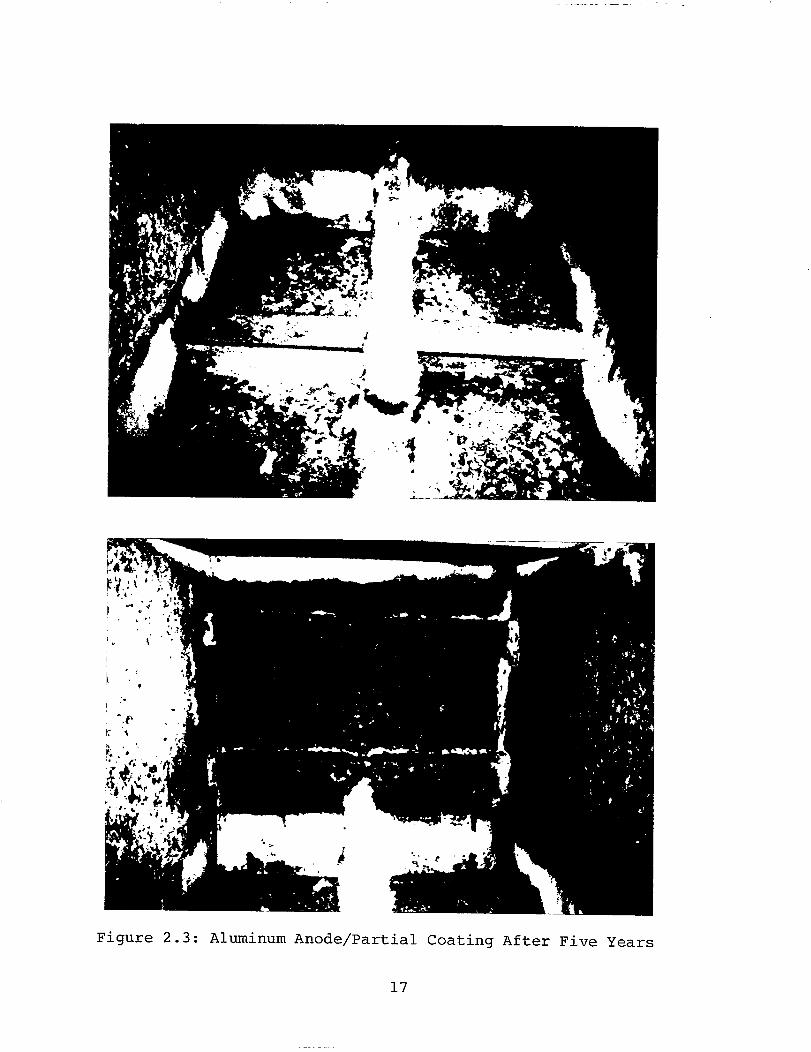
Photographs of Aluminum Anode/Partial CoatingsAfter Five Years
Photographs of High Performance CoatingsAfter Five Years
Photographs of Zinc Anode/Partial CoatingsAfter Five Years
Photographs of Zinc Primer/Aluminum AnodeAfter Five Years
Photographs of Rust Tolerant Epoxy CoatingAfter Twenty-four Cycles
Photographs of Preconstruction Primer/ZincYears
Page
11
11
17
18
19
20
21
22
Table
Table I
Table II
Table III
Table IV
Table V
Table VI
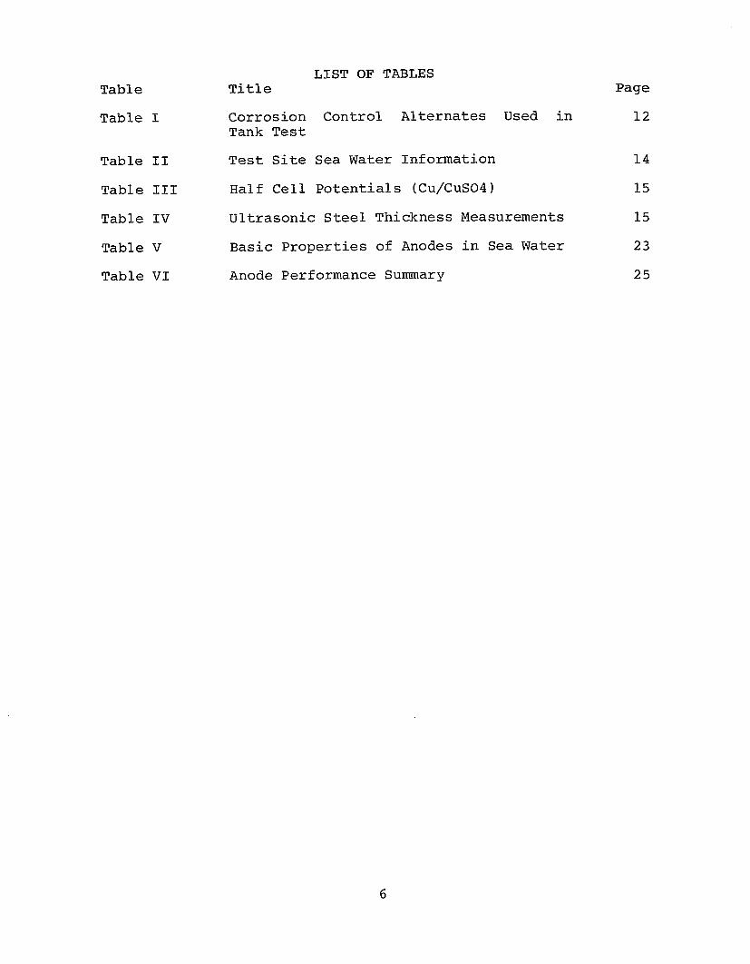
LIST OF TABLESTitle Page
Corrosion Control Alternates Used in 12Tank Test
Test Site Sea Water Information 14
Half Cell Potentials (Cu/CuS04) 15
Ultrasonic Steel Thickness Measurements 15
Basic Properties of Anodes in Sea Water 23
Anode Performance Summary 25
6
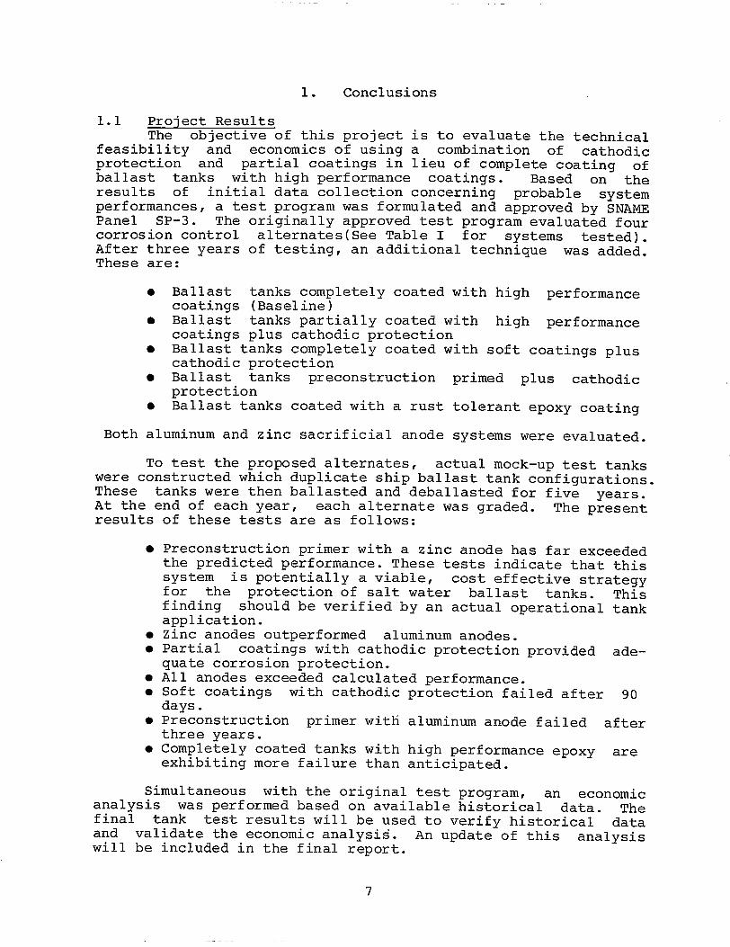
1. Conclusions
1.1 Project ResultsThe objective of this project is to evaluate the technical
feasibility and economics of using a combination of cathodicprotection and partial coatings in lieu of complete coating ofballast tanks with high performance coatings. Based on theresults of initial data collection concerning probable systemperformances, a test program was formulated and approved by SNAMEPanel SP-3. The originally approved test program evaluated fourcorrosion control alternates(See Table I for systems tested).After three years of testing, an additional technique was added.These are:
● Ballast tanks completely coated with high performancecoatings (Baseline)
● Ballast tanks partially coated with high performancecoatings plus cathodic protection
● Ballast tanks completely coated with soft coatings pluscathodic protection
● Ballast tanks preconstruction primed plus cathodicprotection
● Ballast tanks coated with a rust tolerant epoxy coating
Both aluminum and zinc sacrificial anode systems were evaluated.
To test the proposed alternates, actual mock-up test tankswere constructed which duplicate ship ballast tank configurations.These tanks were then ballasted and deballasted for five years.At the end of each year, each alternate was graded. The presentresults of these tests are as follows:
● Preconstruction primer with a zinc anode has far exceededthe predicted performance. These tests indicate that thissystem is potentially a viable, cost effective strategyfor the protection of salt water ballast tanks. Thisfinding should be verified by an actual operational tankapplication.
● Zinc anodes outperformed aluminum anodes.● Partial coatings with cathodic protection provided ade-
quate corrosion protection.● All anodes exceeded calculated performance.● Soft coatings with cathodic protection failed after 90
days.● Preconstruction primer with aluminum anode failed after
three years.● Completely coated tanks with high performance epoxy are
exhibiting more failure than anticipated.
Simultaneous with the original test program, an economicanalysis was performed based on available historical data. Thefinal tank test results will be used to verify historical dataand validate the economic analysis. An update of this analysiswill be included in the final report.
7
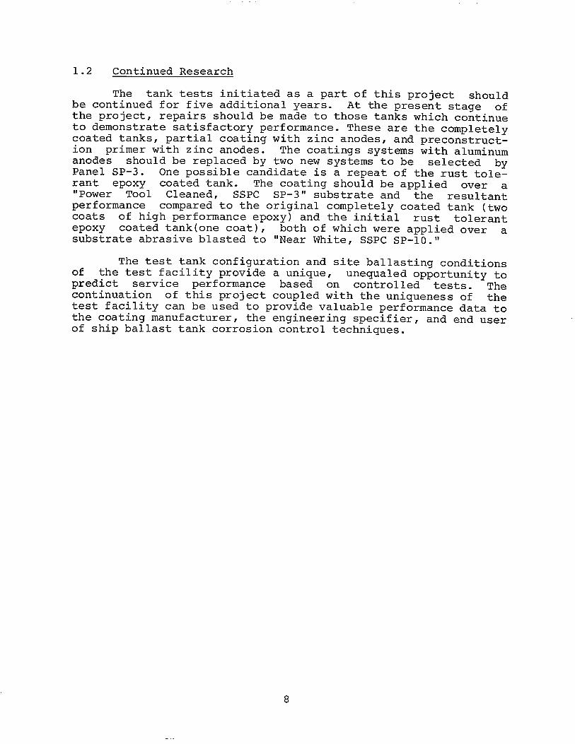
1.2 Continued Research
The tank tests initiated as a part of this project shouldbe continued for five additional years. At the present stage ofthe project, repairs should be made to those tanks which continueto demonstrate satisfactory performance. These are the completelycoated tanks, partial coating with zinc anodes, and preconstruct-ion primer with zinc anodes. The coatings systems with aluminumanodes should be replaced by two new systems to be selected byPanel SP-3. One possible candidate is a repeat of the rust tole-rant epoxy coated tank. The coating should be applied over a“Power Tool Cleaned, SSPC SP-3" substrate and the resultantperformance compared to the original completely coated tank (twocoats of high performance epoxy) and the initial rust tolerantepoxy coated tank(one coat), both of which were applied over asubstrate abrasive blasted to “Near White, SSPC Sp-10.”
The test tank configuration and site ballasting conditionsof the test facility provide a unique, unequaled opportunity topredict service performance based on controlled tests. Thecontinuation of this project coupled with the uniqueness of thetest facility can be used to provide valuable performance data tothe coating manufacturer, the engineering specifier, and end userof ship ballast tank corrosion control techniques.
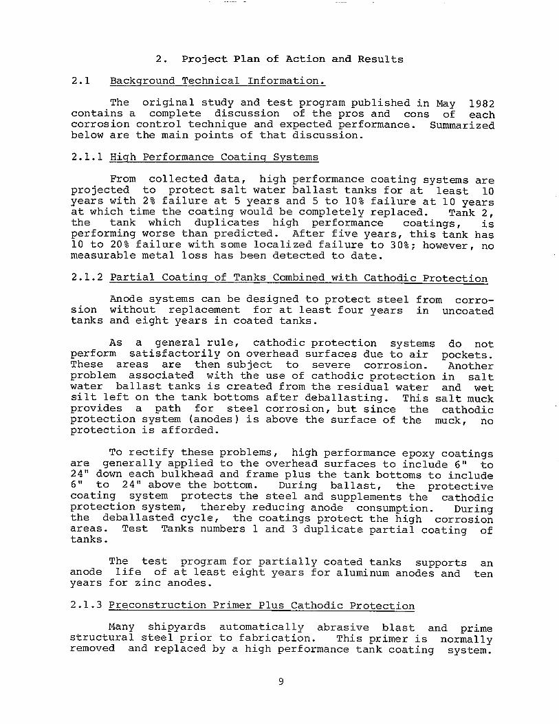
2. Project Plan of Action and Results
2.1 Background Technical Information.
The original study and test program published in May 1982contains a complete discussion of the pros and cons of eachcorrosion control technique and expected performance. Summarizedbelow are the main points of that discussion.
2.1.1 High Performance Coatinq Systems
From collected data, high performance coating systems areprojected to protect salt water ballast tanks for at least 10years with 2% failure at 5 years and 5 to 10% failure at 10 yearsat which time the coating would be completely replaced. Tank 2,the tank which duplicates high performance coatings, isperforming worse than predicted. After five years, this tank has10 to 20% failure with some localized failure to 30%; however, nomeasurable metal loss has been detected to date.
2.1.2 Partial Coatinq of Tanks Combined with Cathodic Protection
Anode systems can be designed to protect steel from corro-sion without replacement for at least four years in uncoatedtanks and eight years in coated tanks.
As a general rule, cathodic protection systems do notperform satisfactorily on overhead surfaces due to air pockets.These areas are then subject to severe corrosion. Anotherproblem associated with the use of cathodic protection in saltwater ballast tanks is created from the residual water and wetsilt left on the tank bottoms after deballasting. This salt muckprovides a path for steel corrosion, but since the cathodicprotection system (anodes) is above the surface of the muck, noprotection is afforded.
To rectify these problems, high performance epoxy coatingsare generally applied to the overhead surfaces to include 6" to24" down each bulkhead and frame plus the tank bottoms to include6" to 24" above the bottom. During ballast, the protectivecoating system protects the steel and supplements the cathodicprotection system, thereby reducing anode consumption. Duringthe deballasted cycle, the coatings protect the high corrosionareas. Test Tanks numbers 1 and 3 duplicate partial coating oftanks.
anodeyears
2.1.3
The test program for partially coated tanks supports anlife of at least eight years for aluminum anodes and ten
for zinc anodes.
Preconstruction Primer Plus Cathodic Protection
Many shipyards automatically abrasive blast and primestructural steel prior to fabrication. This primer is normallyremoved and replaced by a high performance tank coating system.
9
If the tank coating system could be eliminated and the precon-struction primer left in place, many construction dollars couldpossibly be saved. Therefore, this approach was selected as apossible alternative for investigation. Sacrificial anodes wereselected to provide the actual corrosion control mechanism. In-organic zinc was selected as the preconstruction primer. Inorgan-ic zinc primers provide the best shipbuilding handling and steelprotection characteristics during construction. One major limi-ting factor of cathodic protection can be tank geometry. Inthese cases, primers could actually compliment the cathodic pro-tection system by protecting overheads, bottoms, and small pocketareas. This point has been substantiated by the test program.
2.2 Tank Test Results
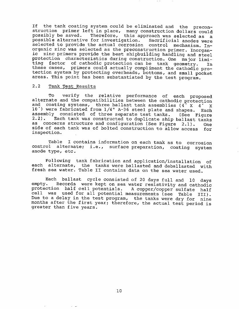
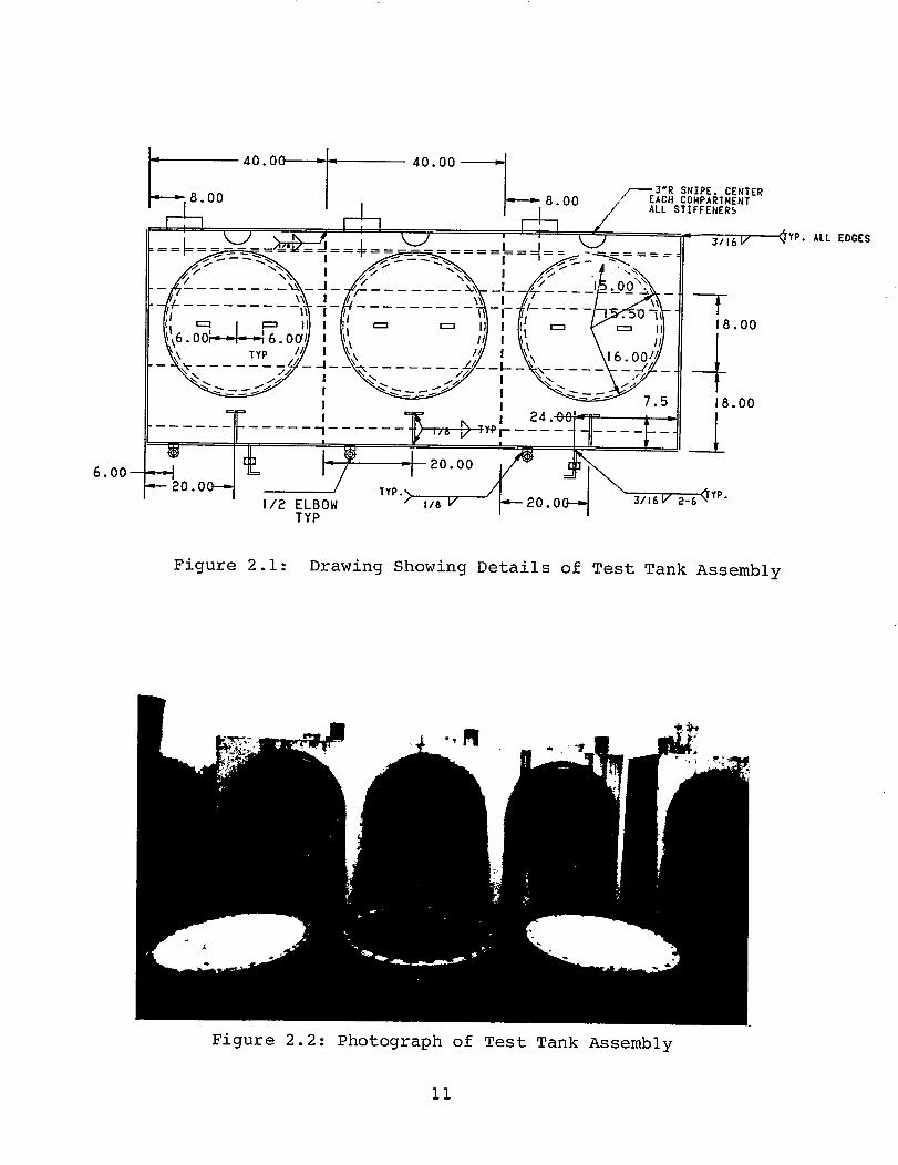
To verify the relative performance of each proposedalternate and the compatibilities between the cathodic protectionand coating systems, three ballast tank assemblies (4’ X 4’ x10') were fabricated from 1/4” A-36 steel plate and shapes. Eachassembly consisted of three separate test tanks. (See Figure2.2). Each tank was constructed to duplicate ship ballast tanksas concerns structure and configuration (See Figure 2.1). Oneside of each tank was of bolted construction to allow access forinspection.
Table I contains information on each tank as to corrosioncontrol alternate; i.e., surface preparation, coating systemanode type, etc.
Following tank fabrication and application/installation ofeach alternate, the tanks were ballasted and deballasted withfresh sea water. Table II contains data on the sea water used.
Each ballast cycle consisted of 20 days full and 10 daysempty. Records were kept on sea water resistivity and cathodicprotection half cell potentials. A copper\copper sulfate halfcell was used for all potential measurements (see Table III).Due to a delay in the test program, the tanks were dry for ninemonths after the first year; therefore, the actual test period isgreater than five years.
10
TYP. ALL EDGES
18.00
18.00
TYPI
Figure 2.1: Drawing Showing Details of Test Tank Assembly
Figure 2.2: Photograph of Test Tank Assembly
11
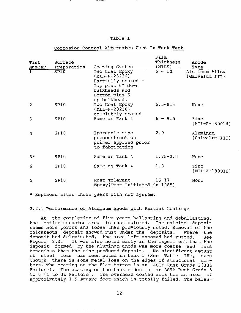
Table I
Corrosion Control Alternates Used In Tank Test
FilmTank Surface Thickness AnodeNumber Preparation Coatinq System (MILS) Type1 SP1O Two Coat Epoxy 6 - 10 Aluminum Alloy
(MIL-P-23236) (Galvalum III)Partially coated -Top plus 6" downbulkheads andBottom plus 6"up bulkhead.
2 SP1O Two Coat Epoxy 6.5-8.5 None(MIL-P-23236)completely coated
3 SP1O Same as Tank 1 6 - 9.5 Zinc(MIL-A-18001H)
4 SP1O Inorganic zinc 2.0 Aluminumpreconstruction (Galvalum III)primer appliedto fabrication
5* SP1O Same as Tank 4
6 SP1O Same as Tank 4
5 SP1O Rust Tolerant
prior
1.75-2.0 None
1.8 Zinc(MIL-A-18001H)
15-17 NoneEpoxy(Test Initiated in 1985)
* Replaced after three years with new system.
2.2.1 Performance of Aluminum Anode with Partial Coatings
At the completion of five years ballasting and deballasting,the entire uncoated area is rust colored. The calcite depositseems more porous and loose than previously noted. Removal of thecalcareous deposit showed rust under the deposits. Where thedeposit had delaminated, the area left exposed had rusted. SeeFigure 2.3. It was also noted early in the experiment that thedeposit formed by the aluminum anode was more coarse and lesstenacious than the zinc produced deposit. No significant amountof steel loss has been noted in tank 1 (See Table IV), eventhough there is some metal loss on the edges of structural mem-bers. The coating on the flat bottom is an ASTM Rust Grade 2(33%Failure). The coating on the tank sides is an ASTM Rust Grade 5to 6 (1 to 3% Failure). The overhead coated area has an area ofapproximately 1.5 square foot which is totally failed. The balan-
12
ce of the overhead area is an ASTM Rust Grade 9 (0.03% Failure).The aluminum anode is approximately 60% depleted. This systemcontinues to protect the tank steel.
2.2.2 Performance of Completely Coated Tank.
Figure 2.4 is a graphic representation of the performance ofthe paint system in Tank 2. The main failure points are in theweld areas and along the top of the roof flange. The overallbreakdown of the coating is judged to be between 10 and 20% per-cent with some localized areas to 30%. As stated earlier thissystem is performing under expectations. There is no metal lossexcept for minor flange faces. The coating system continues toprovide protection.
2.2.3 Performance of Zinc Anode with Partial Coatings
The color of the bare portion of the tank surface is prima-rily the color of the calcareous deposit. See Figure 2.5. Removalof the deposit revealed tight black oxide under the film. Wherethe deposit had been removed, a new deposit has formed. Thecalcareous deposit in Tank 3 is more dense and tenacious thanthat formed with the aluminum anode; however, the deposit wasobserved to be more porous than previously reported. No metalloss was measured and the tank continues to be protected. NOblisters in the tank were detected. This system appears to besuperior to the system in Tank 1 which uses an aluminum anode.The coated flat bottom of the is an ASTM Rust Grade 5 (3% Fai-lure). The coated tank sides are an ASTM Rust Grade 8 (0.1%Failure), and the tank top is an ASTM Rust Grade 9 (0.03% Fai-lure).
2.2.4 Aluminum Anode with Preconstruction Zinc Primer
Early in the test cycle, the aluminum anode seemed to pro-tect the zinc coating and even built up a calcareous deposit onbare welds and other damaged areas. At the end of three years,the calcareous coating was depleted. After five years, the inor-ganic zinc coating is depleted as predicted in the last report.See figure 2.6. The measured anode potential was still suffi-cient to protect the steel; however, the anode is almost depleted.Rust scale was visible on the overhead surfaces; however, thereis no appreciable metal loss on the tank sides. (See para. 1.3)
2.2.5 Performance of Preconstruction Primer Only
Initially, a calcareous deposit was formed on welds anddamaged areas; however, with time this deposit disappeared(approximately 9 months). At the end of the twelfth cycle, all ofthe zinc primer was used up and the steel was just beginning torust. After thirty-six ballast cycles, the tank was beginning tolose metal. Heavy, uniform rust was present. This coating wasreplaced after three years with a rust tolerant epoxy coating(see paragraph 2.2.7).
13
2.2.6 Performance of Zinc Anodes with Preconstruction Primer
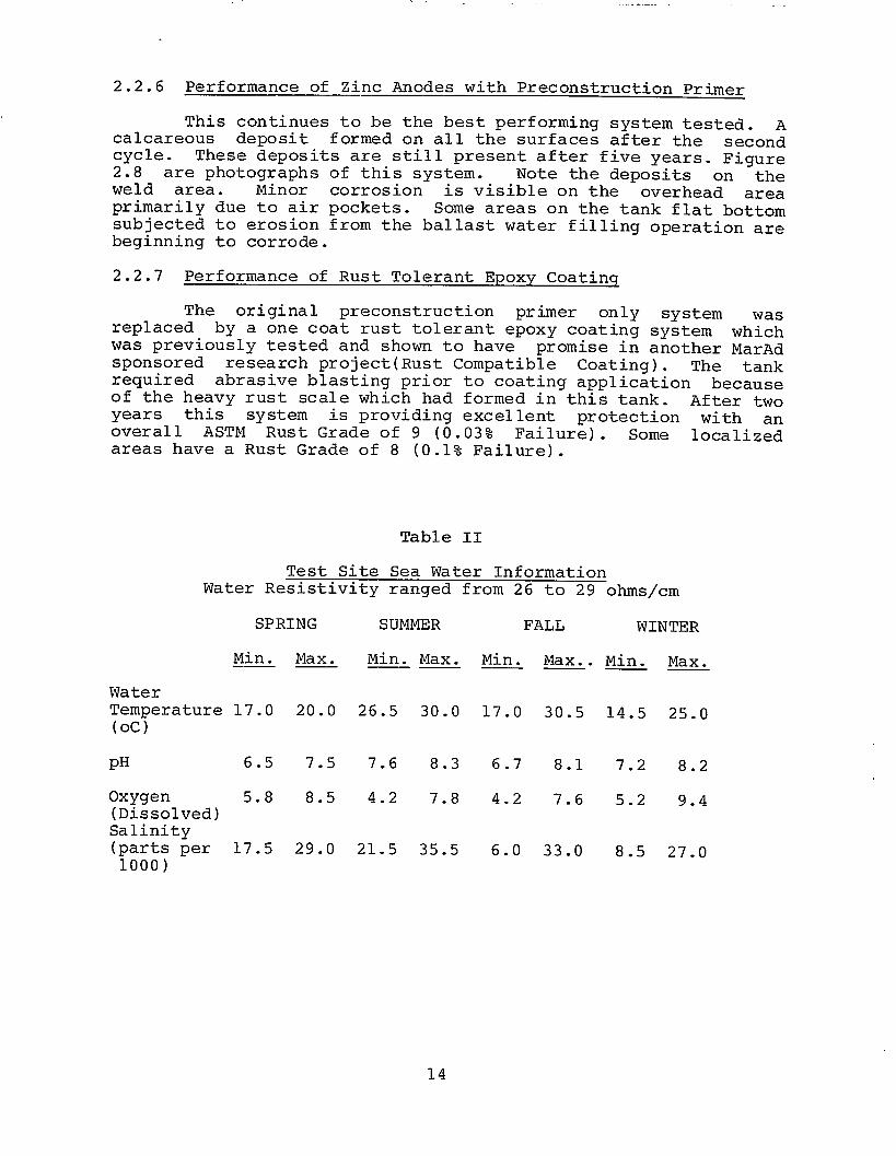
This continues to be the best performing system tested. Acalcareous deposit formed on all the surfaces after the secondcycle. These deposits are still present after five years. Figure2.8 are photographs of this system. Note the deposits on theweld area. Minor corrosion is visible on the overhead areaprimarily due to air pockets. Some areas on the tank flat bottomsubjected to erosion from the ballast water filling operation arebeginning to corrode.
2.2.7 Performance of Rust Tolerant Epoxy Coating
The original preconstruction primer only system wasreplaced by a one coat rust tolerant epoxy coating system whichwas previously tested and shown to have promise in another MarAdsponsored research project(Rust Compatible Coating. The tankrequired abrasive blasting prior to coating application becauseof the heavy rust scale which had formed in this tank. After twoyears this system is providing excellent protection with anover al1 ASTM Rust Grade of 9 (0.03% Failure). Some localizedareas have a Rust Grade of 8 (0.1% Failure).
Table II
Test Site Sea Water InformationWater Resistivity ranged from 26 to 29 ohms/cm
SPRING
Min. Max.
WaterTemperature 17.0 20.0
pH 6.5 7.5
Oxygen 5.8 8.5(Dissolved)Salinity(parts per 17.5 29.01000)
SUMMER
Min. Max.
26.5 30.0
7.6 8.3
4.2 7.8
21.5 35.5
FALL WINTER
Min. Max. Min.
17.0 30.5
6.7 8.1
4.2 7.6
6.0 33.0
14.5
7.2
5.2
8.5
Max.
25.0
8.2
9.4
27.0
14
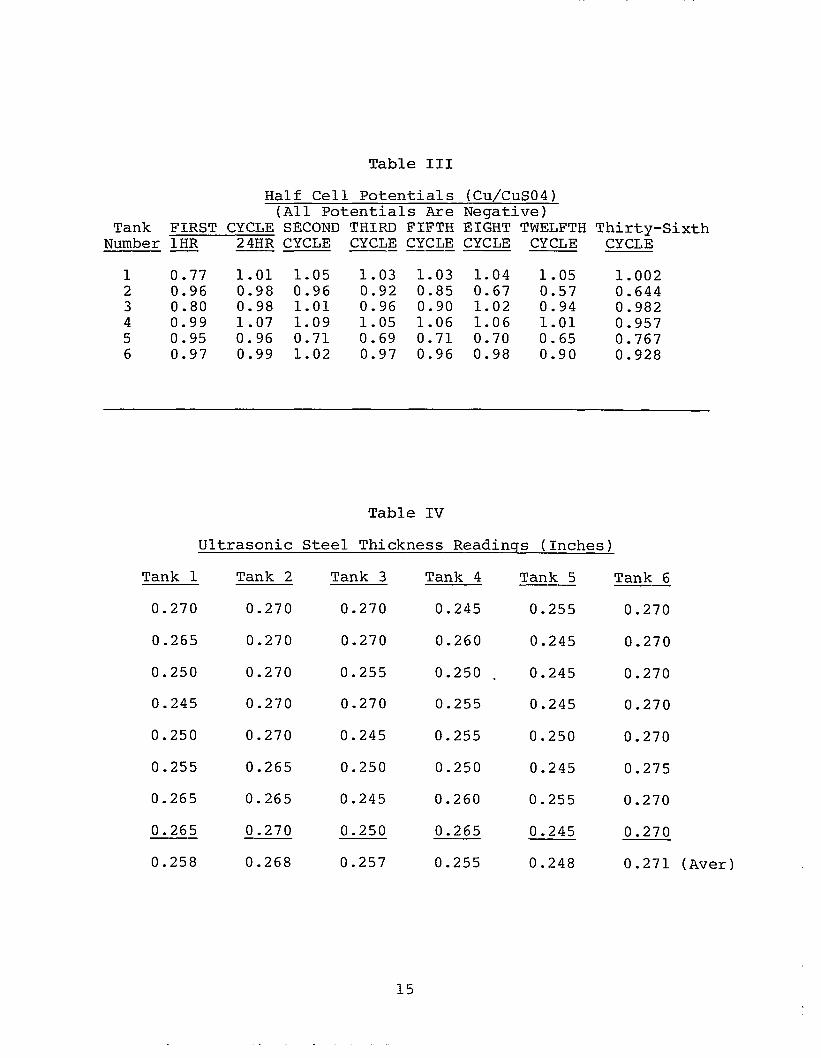
Table III
Half Cell Potentials (Cu/CuS04)(All Potentials Are Negative)
Tank FIRST CYCLE SECOND THIRD FIFTH EIGHT TWELFTH Thirty-SixthNumber lHR 24HR CYCLE CYCLE CYCLE CYCLE CYCLE CYCLE. ..
1 0.77 1.01 1.05 1.03 1.03 1.04 1.05 1.0022 0.96 0.98 0.96 0.92 0.85 0.67 0.57 0.6443 0.80 0.98 1.01 0.96 0.90 1.02 0.94 0.9824 0.99 1.07 1.09 1.05 1.06 1.06 1.01 0.9575 0.95 0.96 0.71 0.69 0.71 0.70 0.65 0.7676 0.97 0.99 1.02 0.97 0.96 0.98 0.90 0.928
Table IV
Ultrasonic Steel Thickness Readings (Inches)
Tank 1
0.270
0.265
0.250
0.245
0.250
0.255
0.265
0.265
0.258
Tank 2
0.270
0.270
0.270
0.270
0.270
0.265
0.265
0.270
0.268
Tank 3
0.270
0.270
0.255
0.270
0.245
0.250
0.245
0.250
0.257
Tank 4
0.245
0.260
0.250
0.255
0.255
0.250
0.260
0.265
0.255
Tank 5
0.255
0.245
0.245
0.245
0.250
0.245
0.255
0.245
0.248
Tank 6
0.270
0.270
0.270
0.270
0.270
0.275
0.270
0.270
0.271 (Aver)
15
2.2.8 Comparison of Ultrasonic Steel Thickness Readings
Table IV contains the measurement data on steel thicknessesafter five years of testing. The steel used to construct the testtanks all came from the same heat. Tanks 1,2 and 3 measurementswere actually made on the same steel plate. The measurementswere made at designated areas on the outside back of each tank.A single plate was used to fabricate the back of all the tanks inthis series. Likewise, the backs of tanks 4,5 and 6 were con-structed from the same plate. Tanks 1 and 3 have almost the sameaverage thickness; whereas, Tank 2, the completely coated tank,has a higher reading; This could mean that the completely coatedtank is providing somewhat better protection as concerns overa11metal loss. The first two and the last two readings in Tanks 1and 3 were made over the coated areas. The other readings in thisseries were made over the cathodic protected areas. Interestingly,Tank 5, the tank which failed totally after less than three yearshas the lowest readings (most metal lose). This Tank has sincebeen recoated. The preconstruction primer in Tank 4 has alsofailed and only the aluminum anode is providing protection. Tank6, the best performer to date, shows the least metal loss.
16
Five Years
17
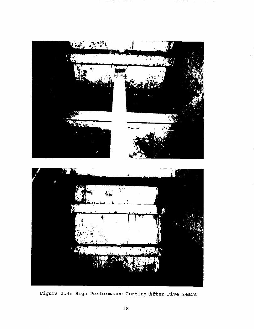
Figure 2.4: High Performance Coating After Five Years
18
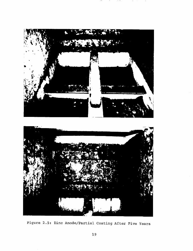
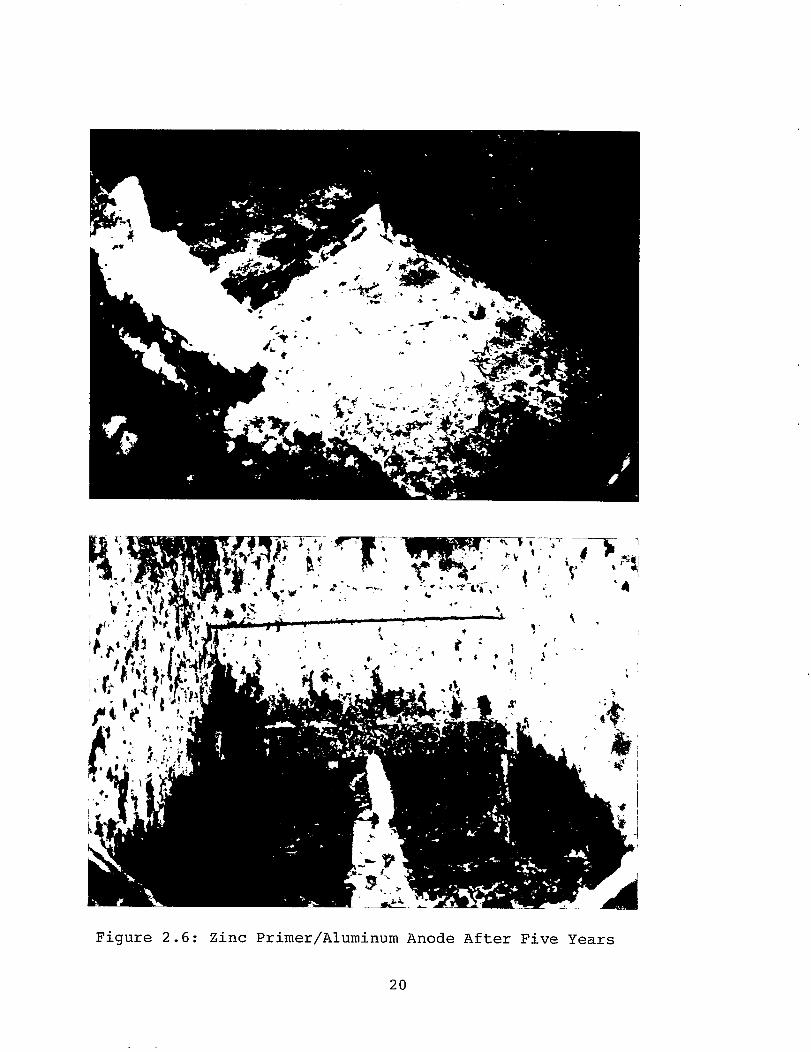
Figure 2.6: Zinc Primer/Aluminum Anode After Five Years
20
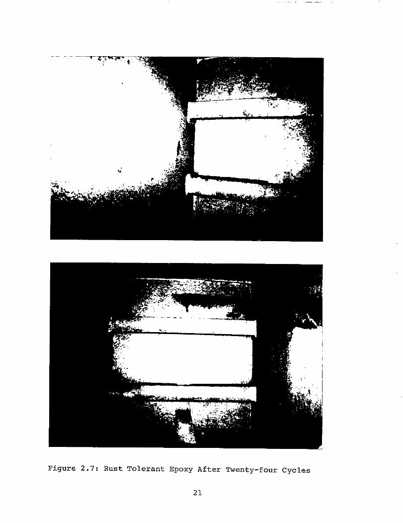
Figure 2.7: Rust Tolerant Epoxy After Twenty-four Cycles
21
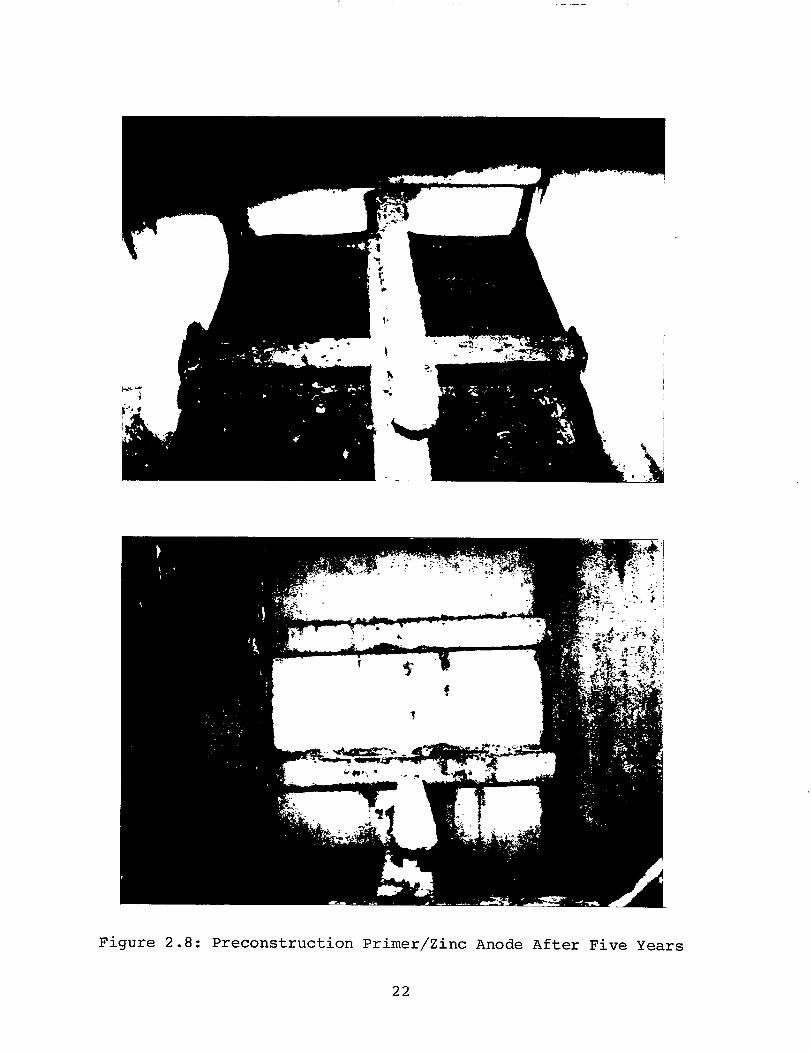
Figure 2.8: Preconstruction Primer/Zinc Anode After Five Years
22
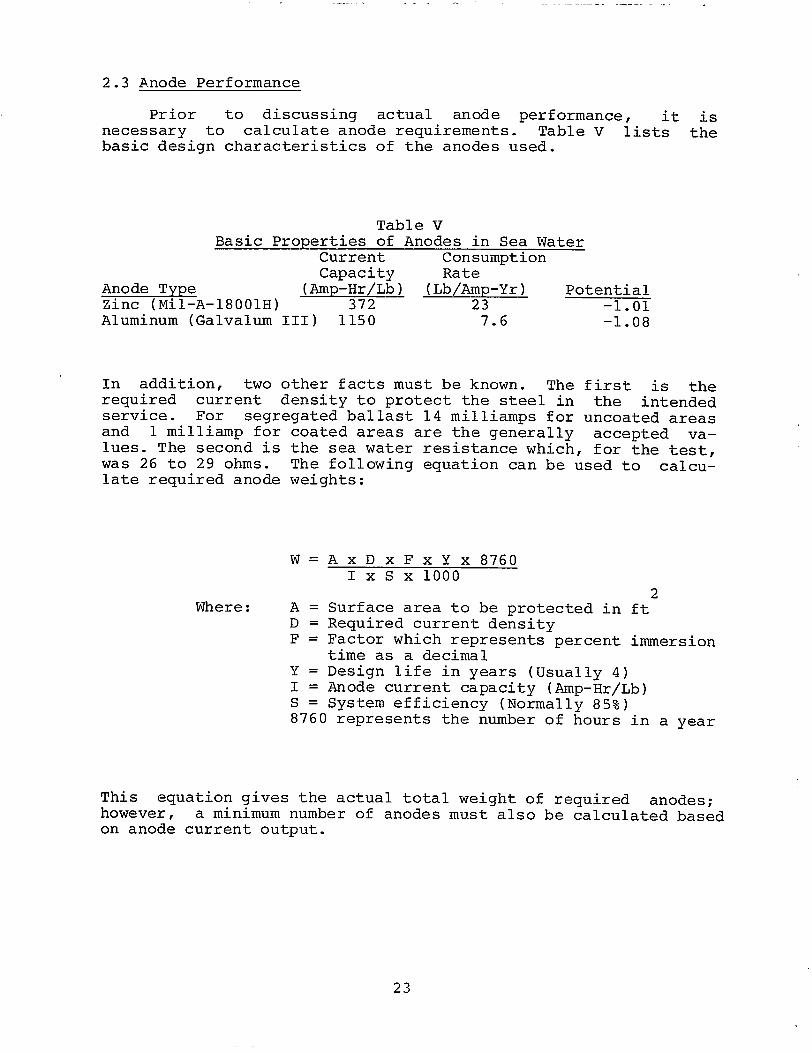
2.3 Anode Performance
Prior to discussing actual anode performance, it isnecessary to calculate anode requirements. Table V lists thebasic design characteristics of the anodes used.
Table VBasic Properties of Anodes in Sea Water
Current ConsumptionCapacity Rate
Anode Type (Amp-Hr/Lb) (Lb/Amp-Yr) PotentialZinc (Mil-A-18001H) 372 23 -1.01Aluminum (Galvalum III) 1150 7.6 -1.08
In addition, two other facts must be known. The first is therequired current density to protect the steel in the intendedservice. For segregated ballast 14 milliamps for uncoated areasand 1 milliamp for coated areas are the generally accepted va-lues. The second is the sea water resistance which, for the test,was 26 to 29 ohms. The following equation can be used to calcu-late required anode weights:
W=AXDXFXYX8760IxSX1OOO
2Where: A = Surface area to be protected in ft
D = Required current densityF = Factor which represents percent immersion
time as a decimalY = Design life in years (Usually 4)I = Anode current capacity (Amp-Hr/Lb)S = System efficiency (Normally 85%)8760 represents the number of hours in a year
This equation gives the actual total weight of required anodes;however, a minimum number of anodes must also be calculated basedon anode current output.
23
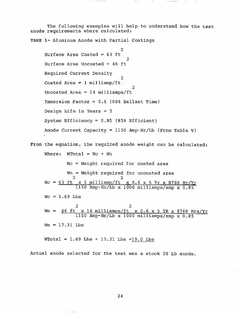
The following examples will help to understand how the testanode requirements where calculated:
TANK
From
1- Aluminum Anode with Partial Coatings
2Surface Area Coated = 63 ft
2Surface Area Uncoated = 46 ft
Required Current Density
Coated Area =
Uncoated Area
21 milliamp/ft
2= 14 milliamps/ft
Immersion Factor = 0.6 (60% Ballast Time)
Design Life in Years = 5
System Efficiency = 0.85 (85% Efficient)
Anode Current Capacity = 1150 Amp-Hr/Lb
the equation, the required anode weight
Where: WTotal = Wc
Wc = Weight
Wn = Weight2
+ Wn
required for coated
(From Table V)
can be calculated:
area
required for uncoated area2
Wc = 63 ft x 1 milliamp/ft x 0.6 x 5 Yr x 8760 Hr/Yr1150 Amp-Hr/Lb x 1000 milliamps\amp x 0.85
Wc = 1.69 Lbs
2 2Wn = 46 ft x 14 milliamps/ft x 0.6 x 5 YRx 8760 Hrs/yr
1150 Amp-Hr/Lb x 1000 milliamps\amp x 0.85
Wn = 17.31 Lbs
WTotal = 1.69 Lbs + 17.31 Lbs =19.O Lbs
Actual anode selected for the test was a stock 20 Lb anode.
24
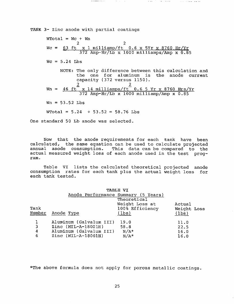
TANK 3- Zinc anode with partial coatings
WTotal = Wc + Wn2 2
Wc = 63 ft x 1 milliamp/ft 0.6 x 5Yr x 8760.Hr/Yr372 Amp-Hr\Lb x 1000 milliamps/Amp x 0.85
WC = 5.24 Lbs
NOTE: The only difference between this calculation andthe one for aluminum is the anode currentcapacity (372 versus 1150).2 2
Wn = 46 ft x 14 milliamps/ft 0.6 5 Yr x 8760 Hrs/Yr372 Amp-Hr/Lb x 1000 milliamp/Amp x 0.85
Wn = 53.52 Lbs
WTotal = 5.24 + 53.52
One standard 50 Lb anode was
= 58.76 Lbs
selected.
Now that the anode requirements for each tank have beencalculated, the same equation can be used to calculate projectedannual anode consumption. This data can be compared to theactual measured weight loss of each anode used in the test prog-ram.
Table VI lists the calculated theoreticalconsumption rates for each tank plus the actualeach tank tested.
TABLE VI
projected anodeweight loss for
Anode performance Summary (5 Years)TheoreticalWeight Loss at Actual
Tank 100% Efficiency Weight LossNumber Anode Type (lbs) (lbs)
1 Aluminum (Galvalum III) 19.0 11.03 Zinc (MIL-A-18001H) 58.8 22.54 Aluminum (Galvalum III) N/A* 16.06 Zinc (MIL-A-18001H) N/A* 16.0
*The above formula does not apply for porous metallic coatings.
25
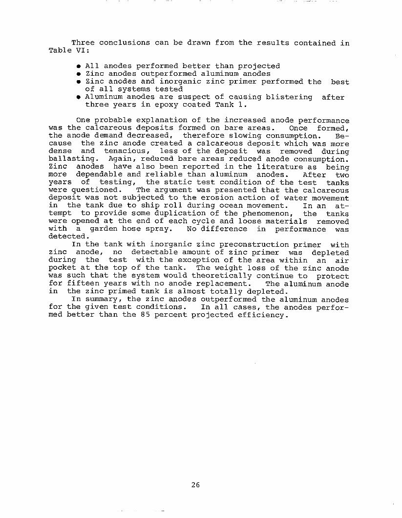
Three conclusions can be drawn from the results contained inTable VI:
● All anodes performed better than projected● Zinc anodes outperformed aluminum anodes● Zinc anodes and inorganic zinc primer performed the best
of all systems tested● Aluminum anodes are suspect of causing blistering after
three years in epoxy coated Tank 1.
one probable explanation of the increased anode performancewas the calcareous deposits formed on bare areas. Once formed,the anode demand decreased, therefore slowing consumption. Be-cause the zinc anode created a calcareous deposit which was moredense and tenacious, less of the deposit was removed duringballasting. Again, reduced bare areas reduced anode consumption.Zinc anodes have also been reported in the literature as beingmore dependable and reliable than aluminum anodes. After twoyears of testing, the static test condition of the test tankswere questioned. The argument was presented that the calcareousdeposit was not subjected to the erosion action of water movementin the tank due to ship roll during ocean movement. In an at-tempt to provide some duplication of the phenomenon, the tankswere opened at the end of each cycle and loose materials removedwith a garden hose spray. No difference in performance wasdetected.
In the tank with inorganic zinc preconstruction primer withzinc anode, no detectable amount of zinc primer was depletedduring the test with the exception of the area within an airpocket at the top of the tank. The weight loss of the zinc anodewas such that the system would theoretically continue to protectfor fifteen years with no anode replacement. The aluminum anodein the zinc primed tank is almost totally depleted.
In summary, the zinc anodes outperformed the aluminum anodesfor the given test conditions. In all cases, the anodes perfor-med better than the 85 percent projected efficiency.
26