Embed Size (px)
Citation preview

747
PART X -- MATERIALS Section No. Page No. Preface ............................................................................................... 748 1001 Hydraulic Cement ................................................................. 749 1002 Asphalt Materials and Additives .......................................... 750 1003 Aggregates ............................................................................ 761 1004 Masonry Units....................................................................... 778 1005 Joint Materials for Pavements and Structures ...................... 779 1006 Concrete and Plastic Pipe ..................................................... 785 1007 Metal Pipe ............................................................................. 790 1008 Paints..................................................................................... 795 1009 Reinforcing Steel and Wire Rope ......................................... 804 1010 Fence and Guard Rail ........................................................... 811 1011 Concrete Curing Materials, Admixtures and Special Finishes.......................................................................... 815 1012 Bridge Railings and Barriers ................................................ 818 1013 Metals.................................................................................... 820 1014 Timber and Timber Preservatives......................................... 825 1015 Signs and Pavement Markings.............................................. 831 1016 Precast Reinforced Concrete Drainage Units ....................... 850 1017 Epoxy Systems...................................................................... 853 1018 Miscellaneous Materials ....................................................... 857 1019 Geotextile Fabrics and Geocomposite Systems ................... 869 1020 Traffic Signals....................................................................... 873
748
Part X Materials Preface
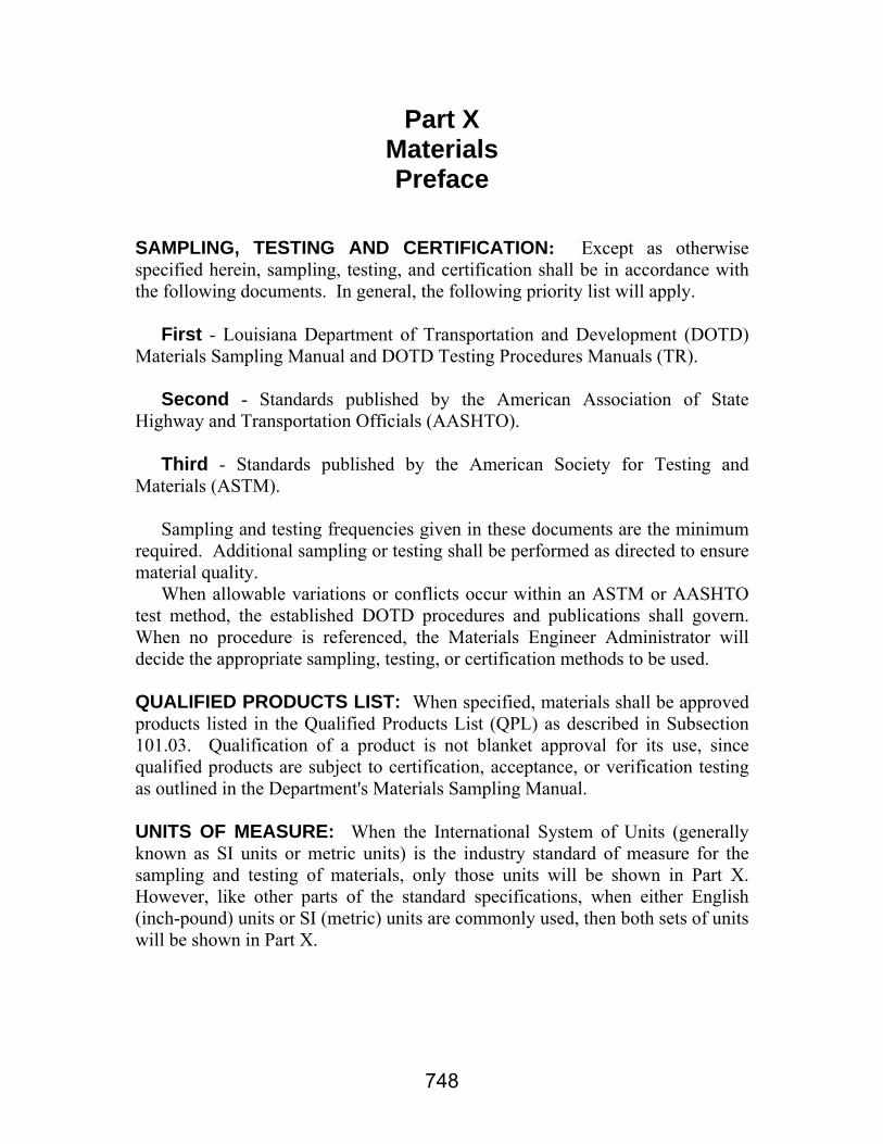
SAMPLING, TESTING AND CERTIFICATION: Except as otherwise specified herein, sampling, testing, and certification shall be in accordance with the following documents. In general, the following priority list will apply. First - Louisiana Department of Transportation and Development (DOTD) Materials Sampling Manual and DOTD Testing Procedures Manuals (TR). Second - Standards published by the American Association of State Highway and Transportation Officials (AASHTO). Third - Standards published by the American Society for Testing and Materials (ASTM). Sampling and testing frequencies given in these documents are the minimum required. Additional sampling or testing shall be performed as directed to ensure material quality. When allowable variations or conflicts occur within an ASTM or AASHTO test method, the established DOTD procedures and publications shall govern. When no procedure is referenced, the Materials Engineer Administrator will decide the appropriate sampling, testing, or certification methods to be used. QUALIFIED PRODUCTS LIST: When specified, materials shall be approved products listed in the Qualified Products List (QPL) as described in Subsection 101.03. Qualification of a product is not blanket approval for its use, since qualified products are subject to certification, acceptance, or verification testing as outlined in the Department's Materials Sampling Manual. UNITS OF MEASURE: When the International System of Units (generally known as SI units or metric units) is the industry standard of measure for the sampling and testing of materials, only those units will be shown in Part X. However, like other parts of the standard specifications, when either English (inch-pound) units or SI (metric) units are commonly used, then both sets of units will be shown in Part X.

749
Section 1001 Hydraulic Cement
1001.01 PORTLAND CEMENT. Portland cement shall be from an approved source listed in QPL 7 and shall comply with AASHTO M 85. (a) Chemical Requirements: The chemical requirements shall be as specified in AASHTO M85. Alkali content calculated as sodium oxide equivalent shall not exceed 0.60 percent by weight for all types of cement. (b) Process Additions: Process additions may be used in amounts not to exceed 3 percent by weight (mass) of portland cement clinker provided it meets the requirements for the cement portion of ASTM C 465 and the test results are submitted to the Department for review and approval. 1001.02 PORTLAND-POZZOLAN CEMENT. Portland-pozzolan cement shall be from an approved source listed in QPL 7, shall comply with AASHTO M 240, Type IP and shall contain 20±5 percent by weight (mass) fly ash (or bottom ash provided it is interground with the cement clinker). The alkali content of portland-pozzolan cement calculated as sodium oxide equivalent shall not exceed 0.60 percent by weight (mass). Fly ash or bottom ash shall comply with AASHTO M 295, Class C or F. 1001.03 MASONRY CEMENT. Masonry cement shall comply with ASTM C 91. 1001.04 PORTLAND BLAST-FURNACE SLAG CEMENT. Portland blast-furnace slag cement shall be from an approved source listed in QPL 7 and shall comply with AASHTO M 240 requirements for Type IS cement. Type IS cement shall contain slag up to 50 percent by weight (mass) of portland blast-furnace slag cement. The alkali content of portland blast-furnace slag cement calculated as sodium oxide equivalent shall not exceed 0.60 percent by weight (mass). Grade 100 and grade 120 ground granulated blast-furnace slag for use in Type IS cement shall comply with AASHTO M 302.

750
Section 1002 Asphalt Materials and Additives
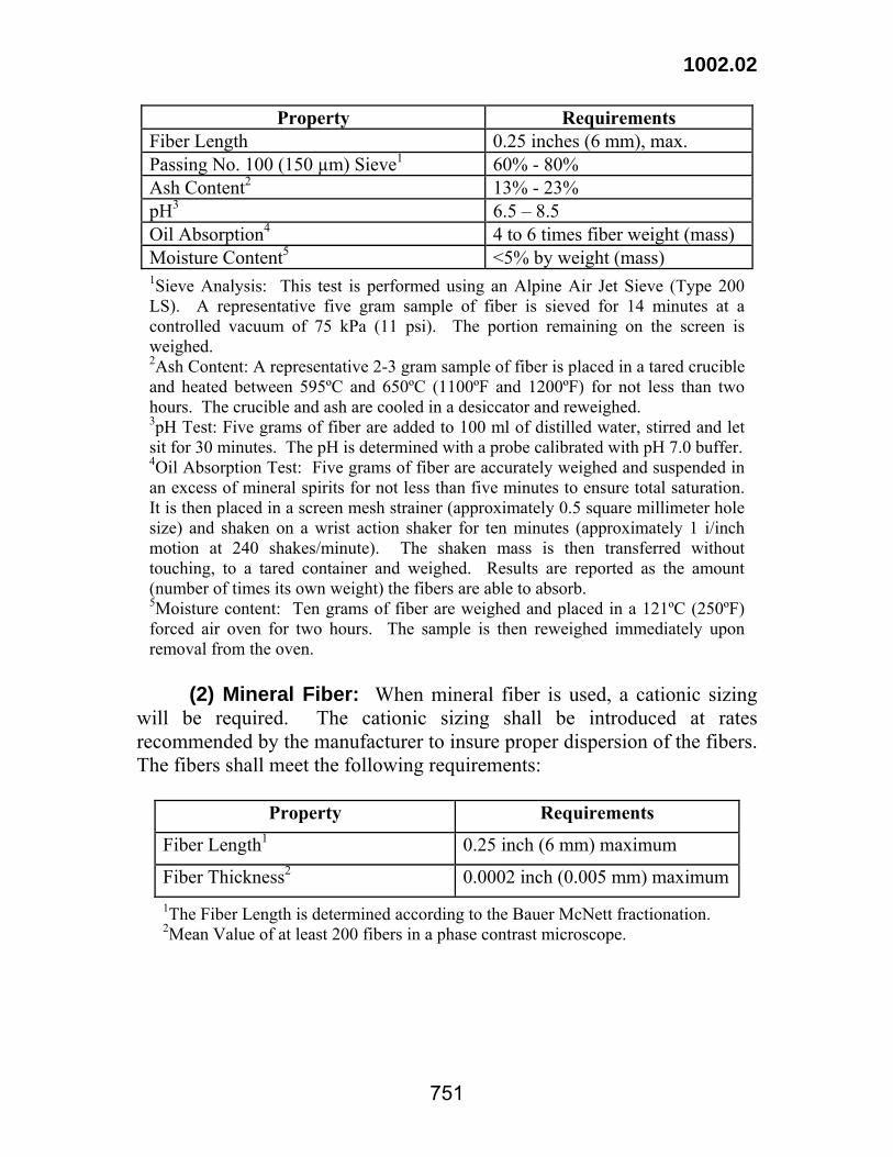
1002.01 ASPHALT. Asphalt shall be prepared by the refining of petroleum. Asphalt shall be uniform in character, free from water, and shall not foam when heated to 350°F (177°C). Asphalt shall be from an approved source listed in QPL 41. Refinery or supplier storage tanks, piping, retorts, booster tanks, and other equipment used in delivering, storing or handling asphaltic materials shall be kept clean and in good operating condition and shall be operated as to avoid contamination of the contents with foreign materials. Final test results for asphalt materials will be applied to the proper table in this Section for conformance to specifications. Samples taken at the refinery or supplier shall comply with specification requirements. When the refinery or supplier sample fails to meet these requirements, the material will be rejected and shall not be shipped to the jobsite. When asphalt materials sampled at the point of delivery do not comply with specification requirements, and in the opinion of the engineer have resulted in an unsatisfactory product based on an investigation, the materials shall be removed and replaced or otherwise corrected at no direct pay. Payment adjustment, when required, shall apply to the quantity of material represented by the sample. If no specific pay item exists, then the invoice price for the material shall be used. 1002.02 ASPHALT MATERIAL ADDITIVES. (a) Anti-Strip: Anti-strip additives for asphalt materials shall be approved products listed in QPL 57 and will be tested in accordance with DOTD TR 317. (b) Silicone: Silicone additives for asphalt materials shall be approved products listed in QPL 22. (c) Polymers: Polymer modified asphalt materials shall be approved products listed in QPL 41. Polymer additives shall be preblended with the asphalt material. In-line blending will not be allowed. (d) Fibers: A cellulose or mineral fiber, pre-approved by the Department, shall be used to prevent draindown or to serve as a filler. (1) Cellulose Fiber: When cellulose fiber is used, it shall meet the following requirements:
1002.02
751
Property Requirements Fiber Length 0.25 inches (6 mm), max. Passing No. 100 (150 µm) Sieve1 60% - 80% Ash Content2 13% - 23% pH3 6.5 – 8.5 Oil Absorption4 4 to 6 times fiber weight (mass) Moisture Content5 <5% by weight (mass) 1Sieve Analysis: This test is performed using an Alpine Air Jet Sieve (Type 200 LS). A representative five gram sample of fiber is sieved for 14 minutes at a controlled vacuum of 75 kPa (11 psi). The portion remaining on the screen is weighed. 2Ash Content: A representative 2-3 gram sample of fiber is placed in a tared crucible and heated between 595ºC and 650ºC (1100ºF and 1200ºF) for not less than two hours. The crucible and ash are cooled in a desiccator and reweighed. 3pH Test: Five grams of fiber are added to 100 ml of distilled water, stirred and let sit for 30 minutes. The pH is determined with a probe calibrated with pH 7.0 buffer. 4Oil Absorption Test: Five grams of fiber are accurately weighed and suspended in an excess of mineral spirits for not less than five minutes to ensure total saturation. It is then placed in a screen mesh strainer (approximately 0.5 square millimeter hole size) and shaken on a wrist action shaker for ten minutes (approximately 1 i/inch motion at 240 shakes/minute). The shaken mass is then transferred without touching, to a tared container and weighed. Results are reported as the amount (number of times its own weight) the fibers are able to absorb. 5Moisture content: Ten grams of fiber are weighed and placed in a 121ºC (250ºF) forced air oven for two hours. The sample is then reweighed immediately upon removal from the oven.
(2) Mineral Fiber: When mineral fiber is used, a cationic sizing will be required. The cationic sizing shall be introduced at rates recommended by the manufacturer to insure proper dispersion of the fibers. The fibers shall meet the following requirements:
Property Requirements
Fiber Length1 0.25 inch (6 mm) maximum
Fiber Thickness2 0.0002 inch (0.005 mm) maximum1The Fiber Length is determined according to the Bauer McNett fractionation. 2Mean Value of at least 200 fibers in a phase contrast microscope.
752
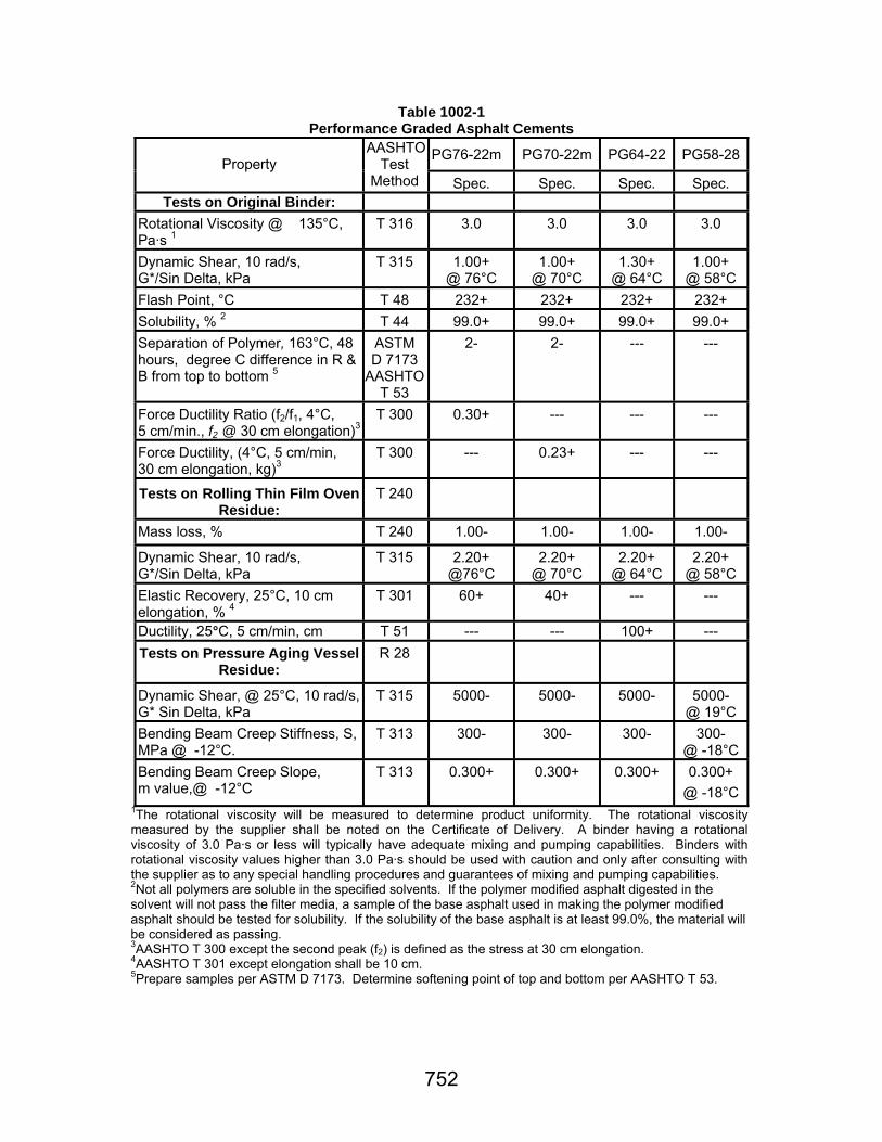
Table 1002-1 Performance Graded Asphalt Cements
PG76-22m PG70-22m PG64-22 PG58-28Property AASHTO
Test Method Spec. Spec.
Spec. Spec.
Tests on Original Binder: Rotational Viscosity @ 135°C, Pa·s 1
T 316
3.0
3.0
3.0
3.0
Dynamic Shear, 10 rad/s, G*/Sin Delta, kPa
T 315
1.00+
@ 76°C
1.00+
@ 70°C
1.30+
@ 64°C
1.00+
@ 58°C Flash Point, °C
T 48
232+
232+
232+
232+
Solubility, % 2
T 44
99.0+
99.0+
99.0+
99.0+ Separation of Polymer, 163°C, 48 hours, degree C difference in R & B from top to bottom 5
ASTM D 7173
AASHTO T 53
2-
2-
---
---
Force Ductility Ratio (f2/f1, 4°C, 5 cm/min., f2 @ 30 cm elongation)3
T 300
0.30+
---
---
---
Force Ductility, (4°C, 5 cm/min, 30 cm elongation, kg)3
T 300
---
0.23+
---
---
Tests on Rolling Thin Film Oven
Residue:
T 240
Mass loss, %
T 240
1.00-
1.00-
1.00-
1.00-
Dynamic Shear, 10 rad/s, G*/Sin Delta, kPa
T 315
2.20+
@76°C
2.20+
@ 70°C
2.20+
@ 64°C
2.20+
@ 58°C Elastic Recovery, 25°C, 10 cm elongation, % 4
T 301
60+
40+
---
---
Ductility, 25°C, 5 cm/min, cm T 51 --- --- 100+ --- Tests on Pressure Aging Vessel
Residue:
R 28
Dynamic Shear, @ 25°C, 10 rad/s, G* Sin Delta, kPa
T 315
5000-
5000-
5000-
5000-
@ 19°C Bending Beam Creep Stiffness, S, MPa @ -12°C.
T 313
300-
300-
300-
300-
@ -18°C Bending Beam Creep Slope, m value,@ -12°C
T 313
0.300+
0.300+
0.300+
0.300+
@ -18°C 1The rotational viscosity will be measured to determine product uniformity. The rotational viscosity measured by the supplier shall be noted on the Certificate of Delivery. A binder having a rotational viscosity of 3.0 Pa·s or less will typically have adequate mixing and pumping capabilities. Binders with rotational viscosity values higher than 3.0 Pa·s should be used with caution and only after consulting with the supplier as to any special handling procedures and guarantees of mixing and pumping capabilities. 2Not all polymers are soluble in the specified solvents. If the polymer modified asphalt digested in the solvent will not pass the filter media, a sample of the base asphalt used in making the polymer modified asphalt should be tested for solubility. If the solubility of the base asphalt is at least 99.0%, the material will be considered as passing. 3AASHTO T 300 except the second peak (f2) is defined as the stress at 30 cm elongation. 4AASHTO T 301 except elongation shall be 10 cm. 5Prepare samples per ASTM D 7173. Determine softening point of top and bottom per AASHTO T 53.

753
Table 1002-2 PG 70-22m Alternate
PG 70-22m Alternate1 Property AASHTO
Test Method Specification
Tests on Original Binder: Rotational Viscosity @ 135°C, Pa·s2
T 316
3.0-
Dynamic Shear, @ 70°C and 10 rad/s, G*/Sin Delta, kPa
T 315
1.50+
Flash Point, °C
T 48
232+
Solubility, %3
T 44
99.0+ Softening Point, Ring & Ball, °C
T 53
70.0+
Tests on Rolling Thin Film Oven Residue: T 240 Mass Loss, %
T 240
1.00-
Dynamic Shear, @ 70°C and 10 rad/s, G*/Sin Delta, kPa
T 315
2.20+
Tests on Pressure Aging Vessel Residue:
R 28
Dynamic Shear, @ 25°C and 10 rad/s, G*Sin Delta, kPa
T 315
5000-
Bending Beam Creep Stiffness, S, @ -12°C, MPa
T 313
300-
Bending Beam Creep Slope, @ -12°C, m value
T 313
0.300+
1Handling of all samples for testing shall be in accordance with ASTM D 4957, Section 7.2, which requires heating the sample in an oven maintained at 190° ± 2°C. Stir the sample occasionally until homogenous and pour in suitable container for testing. Pouring temperatures shall be 180° ± 2°C for all tests. 2The rotational viscosity will be measured to determine product uniformity. The rotational viscosity measured by the supplier shall be noted on the Certificate of Delivery. A binder having a rotational viscosity of 3.0 Pa·s or less will typically have adequate mixing and pumping capabilities. Binders with rotational viscosity values higher than 3.0 Pa·s should be used with caution and only after consulting with the supplier as to any special handling procedures and guarantees of mixing and pumping capabilities. 3Not all polymers are soluble in the specified solvents. If the polymer modified asphalt digested in the solvent will not pass the filter media, a sample of the base asphalt used in making the polymer modified asphalt should be tested for solubility. If the solubility of the base asphalt is at least 99.0%, the material shall be considered as passing.
754
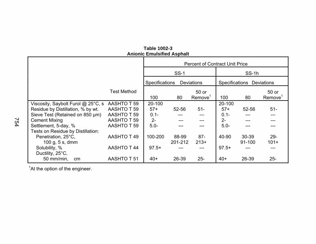
Table 1002-3 Anionic Emulsified Asphalt
Percent of Contract Unit Price
SS-1
SS-1h
Specifications Deviations
Specifications Deviations
Test Method 50 or 100 80 Remove1
50 or
100 80 Remove1 Viscosity, Saybolt Furol @ 25°C, s AASHTO T 59 Residue by Distillation, % by wt. AASHTO T 59 Sieve Test (Retained on 850 µm) AASHTO T 59 Cement Mixing AASHTO T 59 Settlement, 5-day, % AASHTO T 59 Tests on Residue by Distillation: Penetration, 25°C, AASHTO T 49 100 g, 5 s, dmm Solubility, % AASHTO T 44 Ductility, 25°C, 50 mm/min, cm AASHTO T 51
20-100 57+ 52-56 51- 0.1- --- --- 2- --- --- 5.0- --- --- 100-200 88-99 87-
201-212 213+ 97.5+ --- --- 40+ 26-39 25-
20-100 57+ 52-56 51- 0.1- --- --- 2- --- --- 5.0- --- --- 40-90 30-39 29-
91-100 101+ 97.5+ --- --- 40+ 26-39 25-
1At the option of the engineer.

755
Table 1002-4 Cationic Emulsified Asphalt (CRS-2, CMS-2, CSS-1 and CSS-1h)
Percent of Contract Unit Price
CRS-2
CMS-2
CSS-1
CSS-1h
Specifications Deviations
Specifications Deviations
Specifications Deviations
Specifications Deviations
Test Method
50 or 100 80 Remove1
50 or 100 80 Remove1
50 or 100 80 Remove1
50 or 100 80 Remove1
Viscosity, Saybolt Furol @ 50°C, s AASHTO T 59 Saybolt Furol @ 25°C, s AASHTO T 59 Residue by Distillation, AASHTO T 59 % by wt. Oil Distillate by AASHTO T 59 Volume, % Particle Charge AASHTO T 59 Sieve Test (Retained on 850 μm), % AASHTO T 59 Settlement, 5-days, % AASHTO T 59 Tests on Residue by Distillation: Penetration, 25°C, AASHTO T 49 100 g, 5 s, dmm Solubility, % AASHTO T 44 Ductility, 25°C, 5 cm/min, cm AASHTO T 51 Viscosity, 135°C, Pa·s AASHTO TP 48
100-400 --- --- 65+ 61-64 60- 3.0- --- --- Pos. --- Neg. 0.1- --- --- 5.0- --- --- 100-250 84-99 83- 251-266 267+ 97.5+ --- --- 80+ 66-79 65- 0.18+ 0.13-0.17 0.12-
50-450 --- --- --- 65+ 61-64 60- 12.0- --- --- Pos. --- Neg. 0.1- --- --- 5.0- --- --- 100-250 84-99 83- 251-266 267+ 97.5+ --- --- 40+ 26-39 25- --- --- ---
--- --- --- 20-100 57+ 52-56 51- --- --- --- Pos. --- Neg. 0.1- --- --- 5.0- --- --- 100-200 88-99 87-
201-212 213+ 97.5+ --- --- 40+ 26-39 25- --- --- ---
--- --- --- 20-100 57+ 52-56 51- --- --- --- --- --- --- Pos. --- Neg. 0.1- --- --- 5.0- --- --- 40-90 30-39 29-
91-100 101+ 97.5+ --- --- 40+ 26-39 25- --- --- ---
1At the option of the engineer.
756
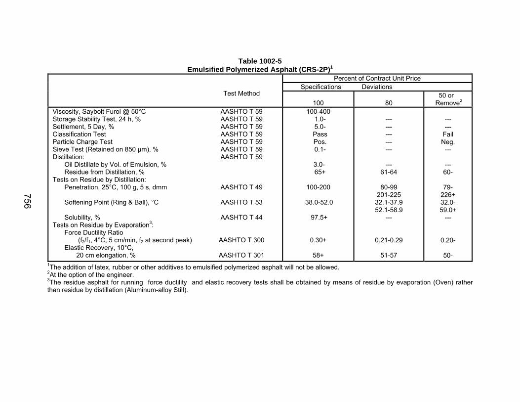
Table 1002-5 Emulsified Polymerized Asphalt (CRS-2P)1
Percent of Contract Unit Price Specifications Deviations
Test Method
100
80 50 or
Remove2 Viscosity, Saybolt Furol @ 50°C AASHTO T 59 Storage Stability Test, 24 h, % AASHTO T 59 Settlement, 5 Day, % AASHTO T 59 Classification Test AASHTO T 59 Particle Charge Test AASHTO T 59 Sieve Test (Retained on 850 µm), % AASHTO T 59 Distillation: AASHTO T 59 Oil Distillate by Vol. of Emulsion, % Residue from Distillation, % Tests on Residue by Distillation: Penetration, 25°C, 100 g, 5 s, dmm AASHTO T 49 Softening Point (Ring & Ball), °C AASHTO T 53 Solubility, % AASHTO T 44 Tests on Residue by Evaporation3: Force Ductility Ratio (f2/f1, 4°C, 5 cm/min, f2 at second peak) AASHTO T 300 Elastic Recovery, 10°C, 20 cm elongation, % AASHTO T 301
100-400 1.0- 5.0- Pass Pos. 0.1-
3.0- 65+
100-200
38.0-52.0
97.5+
0.30+
58+
--- --- --- --- ---
--- 61-64
80-99
201-225 32.1-37.9 52.1-58.9
---
0.21-0.29
51-57
--- ---
Fail Neg.
---
--- 60-
79-
226+ 32.0- 59.0+
---
0.20-
50-
1The addition of latex, rubber or other additives to emulsified polymerized asphalt will not be allowed. 2At the option of the engineer. 3The residue asphalt for running force ductility and elastic recovery tests shall be obtained by means of residue by evaporation (Oven) rather than residue by distillation (Aluminum-alloy Still).

757
Table 1002-6 MC Cutback Asphalt
Percent of Contract Unit Price
MC-30
MC-70
MC-250
Specifications Deviations
Specifications Deviations
Specifications Deviations
Test Method
100
80
50 or
Remove1
100
80
50 or
Remove1
100
80 50 or
Remove1 Flash Point, Open Tag, °C Viscosity, Saybolt Furol @ 25°C, s 60°C, s Distillation Test, Distillate Percentage by Volume of Total Distillate to 360°C to 225°C to 260°C to 316°C Residue from Distillation to 360°C, Volume Percentage of Sample by Difference Tests on Residue by Distillation: Penetration, 25°C, 100 g, 5 s, dmm Solubility, % Ductility, 25°C, for Residues to 200 Penetration, 5 cm/min, cm Ductility, 15.5°C, for Residues of 200-300 Penetration, 5 cm/min, cm
AASHTO T 79AASHTO T 72 AASHTO T 78 AASHTO T 49 AASHTO T 44 AASHTO T 51 AASHTO T 51
38+
75-150
---
0.0-25.0 40.0-70.075.0-93.0
50.0+
120-250
99.0+
100+
100+
---
58-74 151-167
---
--- --- ---
45.1-49.9
102-119 251-268
98.6-98.9
76-99
76-99
---
57- 168+
---
--- --- ---
45.0-
101- 269+ 98.5-
75-
75-
38+
---
35-70
0.0-20.020.0-60.065.0-90.0
55.0+
120-250
99.0+
100+
100+
---
---
24-34 71-81
--- --- ---
50.1-54.9
102-119 251-268
98.6-98.9
76-99
76-99
---
---
23- 82+
--- --- ---
50.0-
101- 269+ 98.5-
75-
75-
66+
---
125-250
0.0-10.015.0-55.060.0-87.0
67.0+
120-250
99.0+
100+
100+
---
---
100-124 251-275
--- --- ---
62.1-66.9
102-119 251-268
98.6-98.9
76-99
76-99
--
---
99- 276+
--- --- ---
62.0-
101- 269+ 98.5-
75-
75-
1At the option of the engineer.

758
Table 1002-7 Cationic Emulsified Petroleum Resin (EPR-1)
Percent of Contract Unit Price
Specifications Deviations
Test Method
100
80
50 or Remove1
Viscosity, Saybolt Furol @ 25°C, s Residue by Evaporation, % by wt. Particle Charge Sieve Test (Retained on 850 µm), % Settlement, 5 Days, %
AASHTO T 59 AASHTO T 59 AASHTO T 59 AASHTO T 59 AASHTO T 59
15-100
57+ Pos. 0.1- 5.0-
10-15
101-150 52-56
--- --- ---
9-
151+ 51-
Neg. --- ---
1At the option of the engineer.
Table 1002-8 AEP Emulsified Asphalt
Percent of Contract Unit Price
Specifications Deviations
Test Method
100
80
50 or Remove1
Viscosity, Saybolt Furol @ 50°C, s Residue by Evaporation, % by wt. Oil Distillate by Volume, % Sieve Test (Retained on 850 µm), % Storage Stability, 24 h, % Settlement, 5 Days, % Test on Residue by Evaporation: Penetration, 25°C, 100 g, 5 s, dmm Solubility, %
AASHTO T 59 AASHTO T 59 AASHTO T 59 AASHTO T 59 AASHTO T 59 AASHTO T 59 AASHTO T 49 AASHTO T 44
15-150
50+
25.0- 0.1- 1.0- 5.0-
250+ 97.5+
10-15
151-200 46-49
--- --- --- ---
--- ---
9-
201+ 45- --- --- --- ---
--- ---
1At the option of the engineer.
759
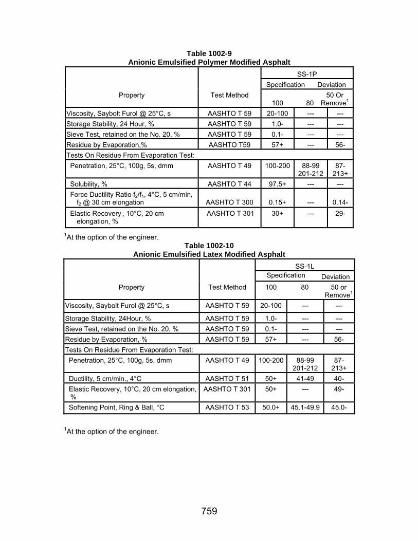
Table 1002-9 Anionic Emulsified Polymer Modified Asphalt
SS-1P
Specification
Deviation Property
Test Method
100
80
50 Or
Remove1 Viscosity, Saybolt Furol @ 25°C, s
AASHTO T 59
20-100
---
---
Storage Stability, 24 Hour, %
AASHTO T 59
1.0-
---
--- Sieve Test, retained on the No. 20, %
AASHTO T 59
0.1-
---
---
Residue by Evaporation,%
AASHTO T59
57+
---
56- Tests On Residue From Evaporation Test: Penetration, 25°C, 100g, 5s, dmm
AASHTO T 49
100-200
88-99
201-212
87-
213+ Solubility, %
AASHTO T 44
97.5+
---
---
Force Ductility Ratio f2/f1, 4°C, 5 cm/min, f2 @ 30 cm elongation
AASHTO T 300
0.15+
---
0.14- Elastic Recovery , 10°C, 20 cm
elongation, %
AASHTO T 301
30+
---
29-
1At the option of the engineer.
Table 1002-10 Anionic Emulsified Latex Modified Asphalt
SS-1L
Specification Deviation
Property
Test Method
100
80
50 or Remove1
Viscosity, Saybolt Furol @ 25°C, s
AASHTO T 59
20-100
---
---
Storage Stability, 24Hour, %
AASHTO T 59
1.0-
---
---
Sieve Test, retained on the No. 20, %
AASHTO T 59
0.1-
---
--- Residue by Evaporation, %
AASHTO T 59
57+
---
56-
Tests On Residue From Evaporation Test: Penetration, 25°C, 100g, 5s, dmm
AASHTO T 49
100-200
88-99
201-212
87-
213+ Ductility, 5 cm/min., 4°C
AASHTO T 51
50+
41-49
40-
Elastic Recovery, 10°C, 20 cm elongation, %
AASHTO T 301
50+
---
49-
Softening Point, Ring & Ball, °C
AASHTO T 53
50.0+
45.1-49.9
45.0-
1At the option of the engineer.

760
Table 1002-11 Hot Applied Modified Asphalt Cements for
Asphaltic Surface Treatment
PAC 15
Spec.
Deviation Property
AASHTO
Test Method
100
90 or
Remove4
Penetration @ 25°C, 100 g., 5 s, dmm
T 49
75-125
74-
126+ Viscosity, @ 60°C, Pa·s
T 202
150+
149-
Rotational Viscosity @ 135°C, Pa·s1 T 316
3.0-
3.1+ Force Ductility Ratio, f2/f1, 4°C, 5cm/min, f2 @ 30 cm elongation2
T 300
0.30+
0.29-
Softening Point, °C
T 53
45+
44-
Flash Point, °C
T 48
230+
228- Separation of Rubber, 163°C, 48 hours difference in R & B from top to bottom sample, °C
DOTD TR 326
2-
---
Tests on Residue from Rolling Thin Film Oven Test:
T 240
Elastic Recovery, 25°C, 10 cm elongation, % 3
T 301
55+
54-
Penetration Retention 25°C, RTFO/Original
T 49
0.60+ 1.00-
0.59- 1.01+
1The rotational viscosity will be measured to determine product uniformity. The rotational viscosity measured by the supplier shall be noted on the Certificate of Delivery. A binder having a rotational viscosity of 3.0 Pa·s or less will typically have adequate mixing and pumping capabilities. Binders with rotational viscosity values higher than 3.0 Pa·s should be used with caution and only after consulting with the supplier as to any special handling procedures and guarantees of mixing and pumping capabilities. 2AASHTO T 300 except the second peak (f2) shall be defined as the stress at 30 cm elongation. 3AASHTO T 301 except the elongation shall be 10 cm. 4At the option of the engineer.
761
Section 1003 Aggregates
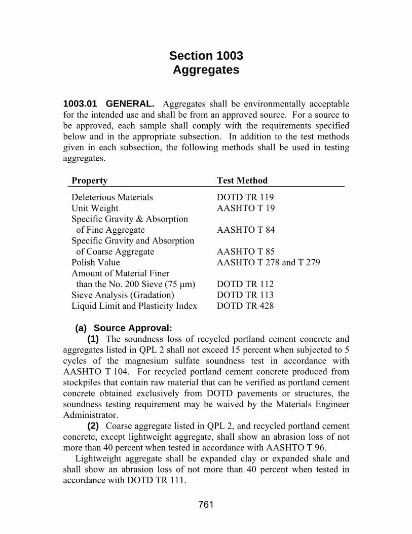
1003.01 GENERAL. Aggregates shall be environmentally acceptable for the intended use and shall be from an approved source. For a source to be approved, each sample shall comply with the requirements specified below and in the appropriate subsection. In addition to the test methods given in each subsection, the following methods shall be used in testing aggregates.
Property Test Method Deleterious Materials Unit Weight Specific Gravity & Absorption of Fine Aggregate Specific Gravity and Absorption of Coarse Aggregate Polish Value Amount of Material Finer than the No. 200 Sieve (75 μm) Sieve Analysis (Gradation) Liquid Limit and Plasticity Index
DOTD TR 119 AASHTO T 19 AASHTO T 84 AASHTO T 85 AASHTO T 278 and T 279 DOTD TR 112 DOTD TR 113 DOTD TR 428
(a) Source Approval: (1) The soundness loss of recycled portland cement concrete and aggregates listed in QPL 2 shall not exceed 15 percent when subjected to 5 cycles of the magnesium sulfate soundness test in accordance with AASHTO T 104. For recycled portland cement concrete produced from stockpiles that contain raw material that can be verified as portland cement concrete obtained exclusively from DOTD pavements or structures, the soundness testing requirement may be waived by the Materials Engineer Administrator. (2) Coarse aggregate listed in QPL 2, and recycled portland cement concrete, except lightweight aggregate, shall show an abrasion loss of not more than 40 percent when tested in accordance with AASHTO T 96. Lightweight aggregate shall be expanded clay or expanded shale and shall show an abrasion loss of not more than 40 percent when tested in accordance with DOTD TR 111.

1003.01
762
(3) Recycled portland cement concrete shall be from dedicated stockpiles produced by an approved concrete crushing operation. The District Laboratory Engineer will inspect and evaluate crushing operations before production of material intended for DOTD projects begins. After being crushed, recycled portland cement concrete shall be reasonably free of asphaltic concrete overlay material, reinforcing steel, joint material, and other debris, but may contain a minimal amount of other base course materials resulting from normal construction methods. Stockpiles produced from raw material verified as portland cement concrete obtained exclusively from DOTD pavements or structures shall be kept separate from other stockpiles. After processing, recycled portland cement concrete shall comply with the requirements specified in the appropriate subsections. Once a stockpile has been sampled for approval, no other material shall be added without prior approval. (4) Reclaimed asphaltic pavement shall be cold planed in accordance with Section 509 or crushed. Reclaimed asphaltic pavement shall be approved either at the time of removal from the roadway or in stockpiles. Stockpiled materials shall be uniform and reasonably free of lightweight aggregate, debris, soil, and other foreign matter. (5) Aggregates for use in portland cement concrete will be tested for alkali reactivity properties in accordance with ASTM C 289. Carbonate rocks for use in portland cement concrete will also be subjected to X-Ray diffraction analysis to determine the presence of potentially reactive components. Aggregates categorized as innocuous by both procedures will not be restricted. Aggregates categorized as potentially deleterious by either of these procedures may be used with combinations of cement and Class F fly ash meeting the requirements of Section 1001 and Subsection 1018.15, respectively. Aggregates categorized as potentially deleterious by either of these procedures will not be allowed with combinations of cement and Class C fly ash. The restriction regarding the use of Class C fly ash will be noted in QPL 2, and will remain in effect until aggregates from the source have been subjected to additional testing and evaluation, and they have been determined by the Materials Engineer Administrator to be innocuous with respect to alkali reactivity. This evaluation shall include one or more of the following procedures as directed by the Materials Engineer Administrator: ASTM C227, ASTM C295, ASTM C586, ASTM C1105, and ASTM C1260. The performance history of the aggregate type, and the source in particular, will be considered in determining the source's potential for detrimental expansion and the procedures used in the evaluation.
1003.02
763
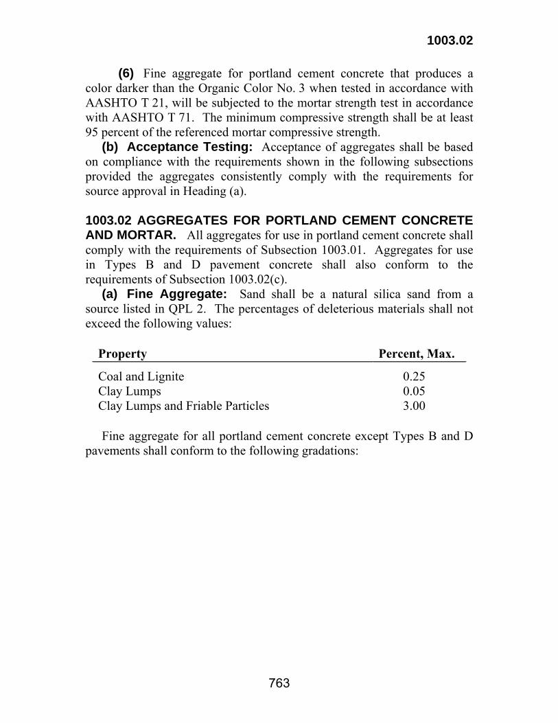
(6) Fine aggregate for portland cement concrete that produces a color darker than the Organic Color No. 3 when tested in accordance with AASHTO T 21, will be subjected to the mortar strength test in accordance with AASHTO T 71. The minimum compressive strength shall be at least 95 percent of the referenced mortar compressive strength. (b) Acceptance Testing: Acceptance of aggregates shall be based on compliance with the requirements shown in the following subsections provided the aggregates consistently comply with the requirements for source approval in Heading (a). 1003.02 AGGREGATES FOR PORTLAND CEMENT CONCRETE AND MORTAR. All aggregates for use in portland cement concrete shall comply with the requirements of Subsection 1003.01. Aggregates for use in Types B and D pavement concrete shall also conform to the requirements of Subsection 1003.02(c). (a) Fine Aggregate: Sand shall be a natural silica sand from a source listed in QPL 2. The percentages of deleterious materials shall not exceed the following values:
Property Percent, Max. Coal and Lignite Clay Lumps Clay Lumps and Friable Particles
0.25 0.05 3.00
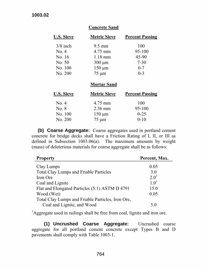
Fine aggregate for all portland cement concrete except Types B and D pavements shall conform to the following gradations:
1003.02
764
Concrete Sand
U.S. Sieve Metric Sieve Percent Passing
3/8 inch No. 4 No. 16 No. 50 No. 100 No. 200
9.5 mm 4.75 mm 1.18 mm 300 μm 150 μm 75 μm
100 95-100 45-90 7-30 0-7 0-3
Mortar Sand
U.S. Sieve Metric Sieve Percent Passing
No. 4 No. 8 No. 100 No. 200
4.75 mm 2.36 mm 150 μm 75 μm
100 95-100
0-25 0-10
(b) Coarse Aggregate: Coarse aggregates used in portland cement concrete for bridge decks shall have a Friction Rating of I, II, or III as defined in Subsection 1003.06(a). The maximum amounts by weight (mass) of deleterious materials for coarse aggregate shall be as follows:
Property Percent, Max. Clay Lumps Total Clay Lumps and Friable Particles Iron Ore Coal and Lignite Flat and Elongated Particles (5:1) ASTM D 4791 Wood (Wet) Total Clay Lumps and Friable Particles, Iron Ore, Coal and Lignite, and Wood
0.05 3.0 2.01 1.01 15.0 0.05 5.0
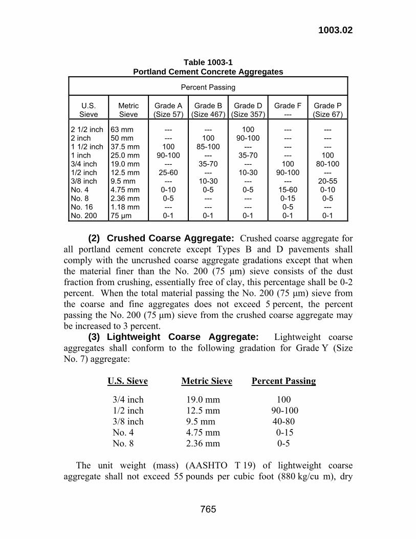
1Aggregate used in railings shall be free from coal, lignite and iron ore. (1) Uncrushed Coarse Aggregate: Uncrushed coarse aggregate for all portland cement concrete except Types B and D pavements shall comply with Table 1003-1.
1003.02
765
Table 1003-1
Portland Cement Concrete Aggregates
Percent Passing
U.S. Sieve
Metric Sieve
Grade A (Size 57)
Grade B
(Size 467)
Grade D
(Size 357)
Grade F
---
Grade P (Size 67)
2 1/2 inch 2 inch 1 1/2 inch 1 inch 3/4 inch 1/2 inch 3/8 inch No. 4 No. 8 No. 16 No. 200
63 mm 50 mm 37.5 mm 25.0 mm 19.0 mm 12.5 mm 9.5 mm 4.75 mm 2.36 mm 1.18 mm 75 μm
--- ---
100 90-100
--- 25-60
--- 0-10 0-5 --- 0-1
---
100 85-100
--- 35-70
--- 10-30
0-5 --- --- 0-1
100
90-100 ---
35-70 ---
10-30 --- 0-5 --- --- 0-1
--- --- --- ---
100 90-100
--- 15-60 0-15 0-5 0-1
--- --- ---
100 80-100
--- 20-55 0-10 0-5 --- 0-1
(2) Crushed Coarse Aggregate: Crushed coarse aggregate for all portland cement concrete except Types B and D pavements shall comply with the uncrushed coarse aggregate gradations except that when the material finer than the No. 200 (75 μm) sieve consists of the dust fraction from crushing, essentially free of clay, this percentage shall be 0-2 percent. When the total material passing the No. 200 (75 μm) sieve from the coarse and fine aggregates does not exceed 5 percent, the percent passing the No. 200 (75 μm) sieve from the crushed coarse aggregate may be increased to 3 percent. (3) Lightweight Coarse Aggregate: Lightweight coarse aggregates shall conform to the following gradation for Grade Y (Size No. 7) aggregate:
U.S. Sieve Metric Sieve Percent Passing
3/4 inch 1/2 inch 3/8 inch No. 4 No. 8
19.0 mm 12.5 mm 9.5 mm 4.75 mm 2.36 mm
100 90-100 40-80 0-15 0-5
The unit weight (mass) (AASHTO T 19) of lightweight coarse aggregate shall not exceed 55 pounds per cubic foot (880 kg/cu m), dry
1003.02
766
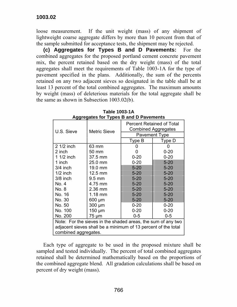
loose measurement. If the unit weight (mass) of any shipment of lightweight coarse aggregate differs by more than 10 percent from that of the sample submitted for acceptance tests, the shipment may be rejected. (c) Aggregates for Types B and D Pavements: For the combined aggregates for the proposed portland cement concrete pavement mix, the percent retained based on the dry weight (mass) of the total aggregates shall meet the requirements of Table 1003-1A for the type of pavement specified in the plans. Additionally, the sum of the percents retained on any two adjacent sieves so designated in the table shall be at least 13 percent of the total combined aggregates. The maximum amounts by weight (mass) of deleterious materials for the total aggregate shall be the same as shown in Subsection 1003.02(b).
Table 1003-1A Aggregates for Types B and D Pavements
Percent Retained of Total Combined Aggregates
Pavement Type U.S. Sieve Metric Sieve
Type B Type D 2 1/2 inch 63 mm 0 0 2 inch 50 mm 0 0-20 1 1/2 inch 37.5 mm 0-20 0-20 1 inch 25.0 mm 0-20 5-20 3/4 inch 19.0 mm 5-20 5-20 1/2 inch 12.5 mm 5-20 5-20 3/8 inch 9.5 mm 5-20 5-20 No. 4 4.75 mm 5-20 5-20 No. 8 2.36 mm 5-20 5-20 No. 16 1.18 mm 5-20 5-20 No. 30 600 μm 5-20 5-20 No. 50 300 μm 0-20 0-20 No. 100 150 μm 0-20 0-20 No. 200 75 μm 0-5 0-5 Note: For the sieves in the shaded areas, the sum of any two adjacent sieves shall be a minimum of 13 percent of the total combined aggregates.
Each type of aggregate to be used in the proposed mixture shall be sampled and tested individually. The percent of total combined aggregates retained shall be determined mathematically based on the proportions of the combined aggregate blend. All gradation calculations shall be based on percent of dry weight (mass).

1003.03
767
1003.03 BASE COURSE AGGREGATES. Aggregates for base course shall comply with the requirements of Subsection 1003.01. (a) Sand-Clay-Gravel: This aggregate shall be composed of a uniform mixture of sand, clay, and siliceous gravel, stone or recycled portland cement concrete. The mixture, as determined by visual inspection, shall be reasonably free from foreign matter. The mixture shall comply with the following gradation:
U.S. Sieve Metric Sieve
(Cement Treated or Stabilized)
Percent Passing
1 1/2 inch No. 4 No. 40 No. 200
37.5 mm 4.75 mm 425 μm 75 μm
95-100 40-65 20-50 10-25
Material passing the No. 40 (425 μm) sieve shall comply with the following requirements:
Cement Treated or Stabilized
Liquid Limit (Max.) Plasticity Index (Max.)
35 12
Stone and recycled portland cement concrete in the mixture shall comply with Subsection 1003.01. (b) Stone: This material shall consist of 100 percent stone and shall comply with the following gradation:
U.S. Sieve Metric Sieve Percent Passing
1 1/2 inch 1 inch 3/4 inch No. 4 No. 40 No. 200
37.5 mm 25.0 mm 19.0 mm 4.75 mm 425 μm 75 μm
100 90-100 70-100 35-65 12-32 5-12

1003.03
768
To facilitate meeting these gradation requirements, a calcium carbonate additive approved by the Materials and Testing Section may be added to the stone. The additive shall be thoroughly blended with the stone by approved methods prior to placement on the project. When tested according to DOTD TR 428, the fraction passing the No. 40 (425 μm) sieve, including any additive, shall have a liquid limit no greater than 25, and a plasticity index of no greater than 4. (c) Recycled Portland Cement Concrete: Recycled portland cement concrete shall be crushed portland cement concrete. After being crushed, recycled portland cement concrete may contain a minimal amount of other base course materials resulting from normal construction methods and shall conform to the following gradation.
U.S. Sieve Metric Sieve Percent Passing 1 1/2 inch 1 inch 3/4 inch No. 4 No. 40 No. 200
37.5 mm 25.0 mm 19.0 mm 4.75 mm 425 µm 75 µm
100 90-100 70-100 35-65 12-32 0-8
The fraction of recycled portland cement concrete passing the No. 40 (425 µm) sieve shall be non-plastic. (d) Crushed Slag: The material shall be 100 percent slag and shall comply with the gradation requirements of Heading (b). 1003.04 AGGREGATES FOR SURFACE COURSE. Aggregates for surface course shall comply with the requirements of Subsection 1003.01. (a) Stone: This material shall consist of 100 percent stone and shall comply with the following gradations:
U.S. Sieve Metric Sieve Percent Passing
1 1/2 inch 3/4 inch No. 4 No. 40 No. 200
37.5 mm 19.0 mm 4.75 mm 425 μm 75 μm
100 50-100 35-65 10-32 3-15
1003.04
769
The fraction of stone passing the No. 40 (425 μm) sieve shall comply with the following requirements.
Liquid Limit (Max.) 25 Plasticity Index (Max.) 4
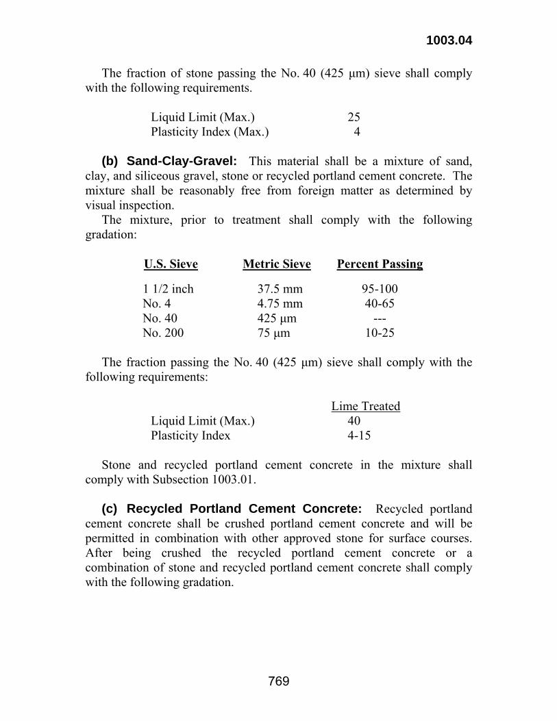
(b) Sand-Clay-Gravel: This material shall be a mixture of sand, clay, and siliceous gravel, stone or recycled portland cement concrete. The mixture shall be reasonably free from foreign matter as determined by visual inspection. The mixture, prior to treatment shall comply with the following gradation:
U.S. Sieve Metric Sieve Percent Passing
1 1/2 inch No. 4 No. 40 No. 200
37.5 mm 4.75 mm 425 μm 75 μm
95-100 40-65
--- 10-25
The fraction passing the No. 40 (425 μm) sieve shall comply with the following requirements: Lime Treated
Liquid Limit (Max.) 40 Plasticity Index 4-15
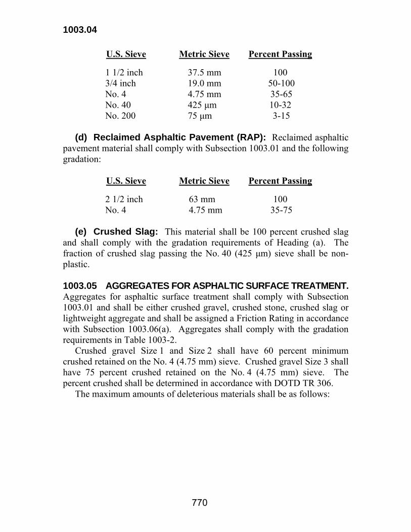
Stone and recycled portland cement concrete in the mixture shall comply with Subsection 1003.01. (c) Recycled Portland Cement Concrete: Recycled portland cement concrete shall be crushed portland cement concrete and will be permitted in combination with other approved stone for surface courses. After being crushed the recycled portland cement concrete or a combination of stone and recycled portland cement concrete shall comply with the following gradation.
1003.04
770
U.S. Sieve Metric Sieve Percent Passing
1 1/2 inch 3/4 inch No. 4 No. 40 No. 200
37.5 mm 19.0 mm 4.75 mm 425 μm 75 μm
100 50-100 35-65 10-32 3-15
(d) Reclaimed Asphaltic Pavement (RAP): Reclaimed asphaltic pavement material shall comply with Subsection 1003.01 and the following gradation:
U.S. Sieve Metric Sieve Percent Passing
2 1/2 inch No. 4
63 mm 4.75 mm
100 35-75
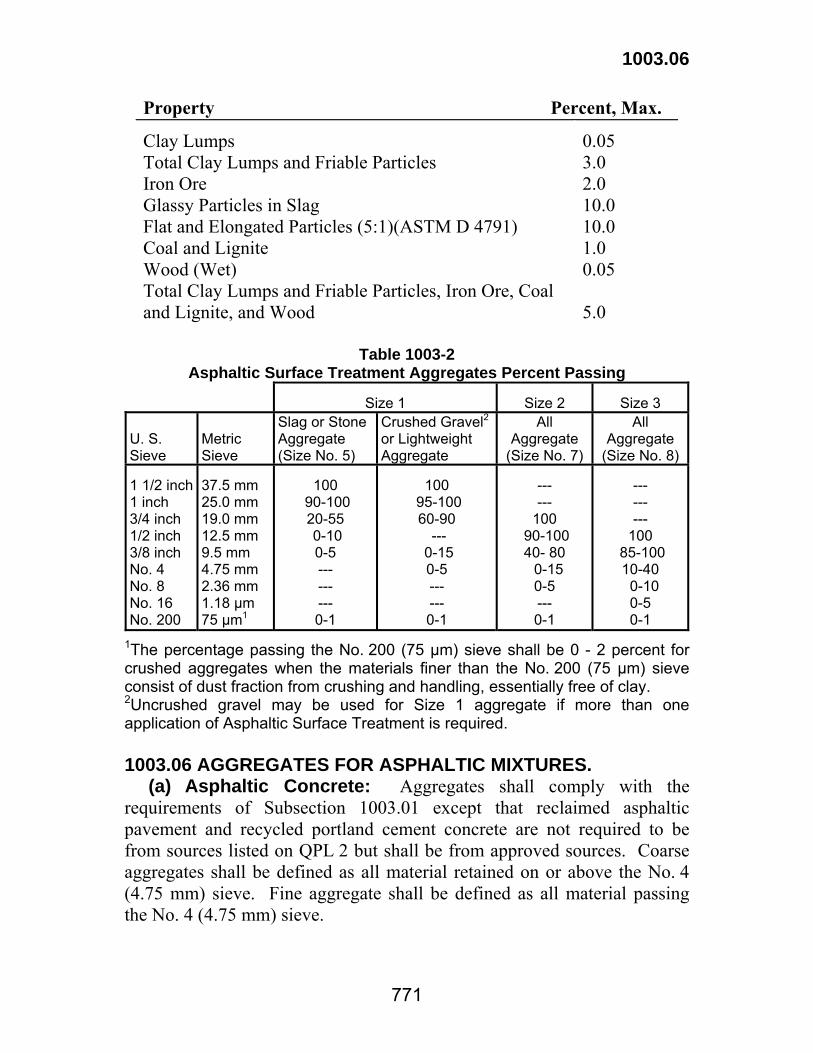
(e) Crushed Slag: This material shall be 100 percent crushed slag and shall comply with the gradation requirements of Heading (a). The fraction of crushed slag passing the No. 40 (425 μm) sieve shall be non-plastic. 1003.05 AGGREGATES FOR ASPHALTIC SURFACE TREATMENT. Aggregates for asphaltic surface treatment shall comply with Subsection 1003.01 and shall be either crushed gravel, crushed stone, crushed slag or lightweight aggregate and shall be assigned a Friction Rating in accordance with Subsection 1003.06(a). Aggregates shall comply with the gradation requirements in Table 1003-2. Crushed gravel Size 1 and Size 2 shall have 60 percent minimum crushed retained on the No. 4 (4.75 mm) sieve. Crushed gravel Size 3 shall have 75 percent crushed retained on the No. 4 (4.75 mm) sieve. The percent crushed shall be determined in accordance with DOTD TR 306. The maximum amounts of deleterious materials shall be as follows:
1003.06
771
Property Percent, Max. Clay Lumps Total Clay Lumps and Friable Particles Iron Ore Glassy Particles in Slag Flat and Elongated Particles (5:1)(ASTM D 4791) Coal and Lignite Wood (Wet) Total Clay Lumps and Friable Particles, Iron Ore, Coal and Lignite, and Wood
0.05 3.0 2.0 10.0 10.0 1.0 0.05 5.0
Table 1003-2
Asphaltic Surface Treatment Aggregates Percent Passing
Size 1
Size 2
Size 3
U. S. Sieve
Metric Sieve
Slag or Stone Aggregate (Size No. 5)
Crushed Gravel2or Lightweight Aggregate
All Aggregate
(Size No. 7)
All Aggregate
(Size No. 8) 1 1/2 inch 1 inch 3/4 inch 1/2 inch 3/8 inch No. 4 No. 8 No. 16 No. 200
37.5 mm 25.0 mm 19.0 mm 12.5 mm 9.5 mm 4.75 mm 2.36 mm 1.18 μm 75 μm1
100
90-100 20-55 0-10 0-5 --- --- --- 0-1
100
95-100 60-90
--- 0-15 0-5 --- --- 0-1
--- ---
100 90-100 40- 80 0-15
0-5 --- 0-1
--- --- ---
100 85-100 10-40 0-10
0-5 0-1
1The percentage passing the No. 200 (75 μm) sieve shall be 0 - 2 percent for crushed aggregates when the materials finer than the No. 200 (75 μm) sieve consist of dust fraction from crushing and handling, essentially free of clay. 2Uncrushed gravel may be used for Size 1 aggregate if more than one application of Asphaltic Surface Treatment is required. 1003.06 AGGREGATES FOR ASPHALTIC MIXTURES. (a) Asphaltic Concrete: Aggregates shall comply with the requirements of Subsection 1003.01 except that reclaimed asphaltic pavement and recycled portland cement concrete are not required to be from sources listed on QPL 2 but shall be from approved sources. Coarse aggregates shall be defined as all material retained on or above the No. 4 (4.75 mm) sieve. Fine aggregate shall be defined as all material passing the No. 4 (4.75 mm) sieve.

1003.06
772
(1) Gravel, Stone, and Crushed Slag: These aggregates shall comply with Subsection 1003.05 for deleterious substances and shall be assigned a Friction Rating as shown in Table 1003-3 and indicated in QPL 2.
Table 1003-3
Aggregate Friction Rating
Friction Rating
Description I
Aggregates that have a Polish Value of greater than 37 or demonstrate the ability to retain acceptable friction numbers for the life of the pavement.
II
Aggregates that have a Polish Value of 35 to 37 or demonstrate the ability to retain acceptable friction numbers for the life of the pavement.
III
Aggregates that have a Polish Value of 30 to 34 or demonstrate the ability to retain acceptable friction numbers for the life of the pavement.
IV
Aggregates with a Polish Value of 20 to 29.
(2) Fine Aggregate: Fine aggregates shall comply with the requirements of asphaltic mixtures. Aggregates shall also comply with the specification requirements for angularity and sand equivalent as shown in Section 502, Table 502-5. a. Fine Aggregate Angularity: Fine aggregate angularity (FAA) shall be determined in accordance with DOTD TR 121. The fine aggregate angularity of the composite mixture shall be determined by calculating the weighted average based on aggregate proportions passing the No. 4 (4.75 mm) sieve and the individual FAA values reported on the job mix formula. When individual aggregate sources do not have sufficient quantities of any of the required sieve sizes, a composite sample shall be tested for the proposed blend. b. Sand Equivalent: Sand equivalent shall be determined in accordance with DOTD TR120. The sand equivalent requirements shall apply to individual natural sand sources only and do not apply to manufactured fines and fines produced from crushing operations. (3) Natural Sand: Natural sand shall be coarse sand or a combination of coarse sand and fine sand which is used in the asphaltic concrete mixture. Natural sand shall consist of clean, hard, durable,

1003.06
773
siliceous grains graded from coarse to fine and shall be reasonably free from vegetative matter or other deleterious materials. The sand shall be nonplastic and no clay balls or clay lumps shall be incorporated into the asphaltic mixture. The gradation shall have a maximum of 25 percent passing the No. 200 (75 μm) sieve. Clay lumps shall not exceed 1.00 percent by weight (mass) when sampled from the stockpile and tested in accordance with DOTD TR 119. The sand equivalent of the portion of the natural sand in the mixture passing the No. 4 (4.75 mm) sieve shall be as shown in Section 502, Table 502-5 when tested in accordance with DOTD TR120. (4) Recycled Portland Cement Concrete: Recycled portland cement concrete source shall meet the requirements of Subsection 1003.02(b)(2). The maximum amount of deleterious materials shall comply with Subsection 1003.05. Recycled portland cement concrete may be used only when specified in the plans or by special provisions. (5) Reclaimed Asphaltic Pavement (RAP): Reclaimed asphaltic pavement shall comply with Subsection 1003.01. (6) Mineral Filler: Mineral filler shall be an approved product listed on QPL 10 and shall consist of limestone dust, pulverized hydrated lime, portland cement, or cement stack dust. Mineral dust collected in bag houses or by other dust collectors at asphaltic concrete plants is not classified as mineral filler. Cement stack dust shall consist of material collected from waste rotary kiln gases discharged through a collector of a cement plant. Mineral filler shall comply with the following gradation:
U.S. Sieve Metric Sieve Percent Passing
No. 30 No. 80 No. 200 No. 270
600 μm 180 μm 75 μm 53 μm
100 95-100 70-100 60-100
Mixtures of aggregate, filler and asphalt, in proportions to meet the requirements of mixes being used, shall have an index of retained Marshall Stability (DOTD TR 313) of at least 85 percent, and a maximum of 1.0 percent volumetric swell (DOTD TR 313). (7) Expanded Clay Coarse Aggregate: Expanded clay coarse aggregate shall consist of angular fragments of uniform density free from

1003.06
774
an excess of foreign matter. These aggregates shall comply with Subsection 1003.05 for deleterious materials. (b) Stone Matrix Asphalt (SMA): All aggregate sources shall be approved and listed on QPL 2. Aggregates shall be composed of clean and durable crushed stone. The combined aggregates shall be in accordance with the design gradation requirements in Table 508-1. (1) Coarse Aggregate: Fifty percent (50%) of the coarse aggregate shall meet Class I friction requirements and the remainder shall meet Class I, II, or III friction requirements. Alternately, 100 percent of the coarse aggregate shall meet Class II friction requirements. At a 3 to 1 ratio in accordance with ASTM D 4791, the flat and elongated particle limit shall be 25 percent maximum by weight (mass). In addition, at a 5 to 1 ratio, the flat and elongated particle limit shall be 5 percent maximum. (2) Fine Aggregate: Fine aggregate shall consist of 100 percent crushed manufactured sand. The Fine Aggregate Angularity, FAA, of each source shall be measured and the calculated fine aggregate blend shall be 45 percent minimum when tested in accordance with DOTD TR 121 (mineral filler excluded). 1003.07 GRANULAR MATERIAL. Granular material shall be non-plastic and siliceous material, and shall comply with Subsection 1003.01 and the following gradation:
U.S. Sieve Metric Sieve Percent Passing
1/2 inch No. 10 No. 200
12.5 mm 2.00 mm 75 μm
100 75-100
0-10 1003.08 BEDDING MATERIAL. Bedding materials shall consist of stone, recycled portland cement concrete, or a mixture of either recycled portland cement concrete, gravel, crushed slag, or stone with granular material complying with Subsection 1003.01. (a) Stone or Recycled Portland Cement Concrete: Stone or recycled portland cement concrete shall comply with Subsection 1003.04. (b) Sand-Aggregate: The sand-aggregate material shall be a natural or artificial mixture of sand and gravel, crushed slag, recycled portland cement concrete, or other approved aggregate listed in this subsection. Material passing the No. 40 (425 μm) sieve shall be nonplastic. The

1003.09
775
mixture shall be free of foreign matter as determined by visual inspection and shall comply with the following gradation prior to placement.
U.S. Sieve Metric Sieve Percent Passing
1 1/2 inch No. 4 No. 10 No. 200
37.5 mm 4.75 mm 2.00 mm 75 μm
95-100 30-50 20-45 0-10
(c) Mixtures: Recycled portland cement concrete, gravel, stone, or crushed slag shall be mixed with 35±5 percent granular material by volume. The mixture shall be verified by proof of material deliveries. (1) Gravel: Gravel shall comply with the following gradation.
U.S. Sieve Metric Sieve Percent Passing
1 1/2 inch No. 4 No. 200
37.5 mm 4.75 mm 75 μm
95-100 0-15 0-2
(2) Recycled Portland Cement Concrete, Crushed Slag, or Stone: Recycled portland cement concrete, crushed slag or stone shall conform to the following gradation:
U.S. Sieve Metric Sieve Percent Passing
1 1/2 inch 3/4 inch No. 4
37.5 mm 19.0 mm 4.75 mm
95-100 40-85 0-15
(3) Granular Material: Granular Material shall comply with Subsection 1003.07. 1003.09 NONPLASTIC EMBANKMENT. Nonplastic embankment materials shall be an approved sand, stone, or blended calcium sulfate. The maximum organic content shall be 4.0 percent. (a) Sand: Sand embankment shall consist of nonplastic material with at least 75 percent passing the No. 4 (4.75 mm) sieve and containing not more than 15 percent passing the No. 200 (75 μm) sieve when tested in accordance with DOTD TR 112 and DOTD TR 113.

1003.09
776
(b) Stone: Stone shall be coarse stone listed on QPL 2 with a dry rodded unit weight (mass) of no greater than 95 pounds per cubic foot (1520 kg/cu m) when tested in accordance with AASHTO T19. Stone shall comply with the following gradation:
U.S. Sieve Metric Sieve Percent Passing
2 inch 1 1/2 inch 3/4 inch No. 4
50 mm 37.5 mm 19.0 mm 4.75 mm
100 85 - 100 35 - 88 0 - 10
(c) Blended Calcium Sulfate: Blended calcium sulfate embankment material shall consist of calcium sulfate, from a source approved by the Materials and Testing Section, blended with an approved aggregate. The source shall have a quality control program approved by the Materials and Testing Section. The source shall have been given environmental clearance by the Department of Environmental Quality for the intended use, and written evidence of such environmental clearance shall be on file at the Materials and Testing Section. DOTD monitoring for compliance with environmental regulations will be limited to the pH testing listed below. The blended material shall be non-plastic and reasonably free from organic and foreign matter. The pH shall be a minimum of 5.0 when tested in accordance with DOTD TR 430. Should the source of the aggregate that is blended with the calcium sulfate change, re-evaluation will be required. The blended embankment material shall consist of 25 to 75 percent passing the No. 4 (4.75 mm) sieve when tested in accordance with DOTD TR 113 modified to include a drying temperature not to exceed 140°F (60°C). 1003.10 AGGREGATE FOR SUBGRADE LAYER. Aggregate for subgrade layers shall consist of either stone, crushed slag, recycled portland cement concrete, or blended calcium sulfate complying with Subsection 1003.01 and the following. (a) Stone, Crushed Slag, or Recycled Portland Cement Concrete: Stone, crushed slag, or recycled portland cement concrete shall comply with Subsection 1003.03. (b) Blended Calcium Sulfate: Blended calcium sulfate shall comply with Subsection 1003.09 except that when tested in accordance with DOTD TR 113, modified to include a maximum drying temperature

1003.10
777
of 140°F (60°C), blended calcium sulfate shall comply with the following gradation.
U.S. Sieve Metric Sieve Percent Passing
1 inch 3/4 inch No. 4 No. 200
25.0 mm 19.0 mm 4.75 mm 75 μm
90-100 70-100 25-75 0-25

778
Section 1004 Masonry Units
1004.01 SEWER BRICK. Sewer brick shall be made from clay, shale or concrete. Brick made from clay or shale for use in junction boxes, catch basins, arches, manholes and for backings shall comply with AASHTO M 91, Manhole Brick, Grade MM. Concrete brick shall comply with ASTM C 139, except that the minimum thickness of each unit shall not be less than 3 5/8 inches (90 mm). 1004.02 BUILDING BRICK. (a) Building brick made from clay or shale for use in brick masonry shall comply with AASHTO M 114, Grade SW. (b) Concrete building brick for use in masonry buildings shall comply with ASTM C 55, Grade N-II. 1004.03 CONCRETE BUILDING BLOCK. Concrete hollow load-bearing building block shall comply with ASTM C 90, Grade N-II. 1004.04 CELLULAR CONCRETE BLOCKS. Cellular concrete blocks shall be manufactured by machines employing high vibratory compaction. The blocks shall comply with ASTM C 90, Type II, except the oven-dry weight (mass) of concrete shall be at least 130 pounds per cubic foot (2.1 Mg/cu m) based on bulk specific gravity. Permissible block dimension variations will be as directed.
779
Section 1005 Joint Materials for Pavements and Structures
1005.01 PREFORMED JOINT FILLERS. (a) Preformed Resilient Bituminous Types: Fillers shall consist of preformed strips which have been formed from cane or other suitable fibers of a cellular nature securely bound together and uniformly saturated with a suitable bituminous binder, or strips which have been formed from clean, granulated cork particles securely bound together by a suitable bituminous binder and encased between two layers of felt. The type shall be as specified and shall conform to AASHTO M 2l3. (b) Wood Fillers: Bottom boards shall be clear heart redwood. Top boards shall be any type of wood which is free from defects and meets dimensional requirements. Occasional medium surface checks will be permitted provided the board is free of defects that will impair its usefulness. Boards shall not vary from specified dimensions in excess of the following tolerances:
Tolerance, inches Tolerance, mm Thickness -0, +1/16 -0, +2 Depth ±1/8 ±3 Length ±1/4 ±6
The load required to compress the material in an oven-dry condition to 50 percent of its original thickness shall not exceed 1750 psi (12 MPa). (c) Preformed Bituminous Type: Bituminous preformed expansion joint filler shall consist of bituminous (asphalt or tar) mastic composition, formed and encased between two layers of bituminous impregnated felt. The preformed filler shall conform to ASTM D 994. (d) Preformed Asphalt Ribbon: This filler shall consist of preformed strips of bitumen and inert filler material conforming to the following requirements:

1005.01
780
Thickness, mm ............................................................................3-5 Depth tolerance, mm .................................................................... ±3 Weight, kg/100 sq m, Min. ........................................................ 245 Tensile Strength, kg/100 mm width, Min. ................................... 90 Bitumen, % by wt (ASTM D 545), Min. .................................... 60
The tensile strength is determined by pulling a 25-by-150-mm sample at a 500-mm/min separation rate. This material shall be resistant to cracking, tearing or permanent deformation under normal handling and installation procedures. It shall be sufficiently rigid to enable it to form a straight joint. (e) Preformed Closed Cell Polyethylene Joint Filler: The joint filler shall comply with ASTM D 7174, Type I. This material shall be used with an adhesive-lubricant. Joint fillers and adhesive-lubricants shall be approved products listed in QPL 18. (f) Preformed Rubber: This filler shall consist of polyurethane bonded recycled rubber in accordance with AASHTO M 153. 1005.02 POURED AND EXTRUDED JOINT SEALANT. (a) Hot Poured Rubberized Asphaltic Type: This material shall comply with ASTM D6690, Type II. The sealant and backer materials shall be approved products listed in QPL 67. Backer materials of the appropriate size shall comply with ASTM D5249, Type I. (b) Polyurethane Sealants: This joint system shall be either a 1- or 2-component, pourable or extrudable sealant, with required primers and backer material. It shall cure to a solid rubber-like material able to withstand both tension and compression. Polyurethane polymer sealant with required primers and backer materials shall be approved products listed in QPL 5. Backer material of the appropriate size shall comply with ASTM D5249, Type 2 without the heat resistant requirement or Type 3. The container shall be labeled with the name and type of material, batch number, manufacture date, and expiration date. The material shall comply with the following requirements.

1005.02
781
Property Test Method1 Requirements Flow, mm, Max AASHTO T 187 3.0 Tack-Free Time, h, Max. ASTM C 679 72 Bond, Defect, mm, Max. ASTM D 5893 6.0 Resilience, %, Min. ASTM D 5329 75 Ball Penetration ASTM D 5329 5-20 Resilience (after heat aging @70±1°C for 24±2h), %, Min. ASTM D 5329 75 Artificial Weathering ASTM D 5893 Pass Ozone Resistance (Exposure to100 ASTM D 1149 No Cracks pphm ozone for 100 h @ 40°C, sample under 20% strain or bent loop) Weight (mass) loss, %, Max. ASTM C 792 10 Infrared Charts DOTD TR 610 Activator Pass Base Pass 1All specimens shall be cured at standard laboratory conditions for a minimum of 72 hours prior to beginning any test. (c) Silicone Sealant (Single Component): The silicone joint sealant shall comply with ASTM D 5893. Backer material of the appropriate size shall comply with ASTM D 5249, Type 3. The silicone sealant, backer materials and primers, if required, shall be approved products listed in QPL 42. The container shall be labeled with the name and address of the manufacturer, the trade name of the sealant, classification of the sealant (non-sag or self-leveling), batch number, manufacture date, and expiration date. (d) Silicone Sealant (Two Component - Rapid Cure): The two component silicone joint sealant shall comply with ASTM D5893 and meet the requirements for single component sealants when mixed and prepared in accordance with the manufacturer's recommendations. Backer material of the appropriate size shall conform to ASTM D5249, Type 3. The silicone sealant, backer materials and primers, if required, shall be approved products listed in QPL 42. The container shall be labeled with the name and address of the manufacturer, the trade name of the sealant, classification of the sealant (non-sag or self-leveling), batch number, manufacture date, and expiration date.

1005.03
782
1005.03 PREFORMED ELASTOMERIC COMPRESSION JOINT SEALS. (a) Seals: This joint system shall be an approved product listed in QPL 6. Uncompressed depth of the seal shall be equal to or greater than the uncompressed width of the seal. Actual width of the seal shall not be less than the nominal width of the seal. The seal will be tested for compression-deflection in accordance with DOTD TR 612. (1) Pavement Use: The material shall comply with ASTM D 2628 with the following exceptions: a. The test for ozone resistance may be determined by the bent loop test method. b. The seal shall exert a minimum pressure of 3 psi (20 kPa) at 80 percent of nominal width, and a maximum of 25 psi (170 kPa) at 50 percent of nominal width. Minimum seal pressure for expansion joints shall be 4 psi (27 kPa) at 80 percent of nominal width and 25 psi (170 kPa) maximum at 50 percent of nominal width. (2) Bridge Use: The seal shall comply with ASTM D 3542 and the seal shall exert a minimum pressure of 4 psi (27 kPa) at 80 percent of nominal width. (b) Adhesive-Lubricant: The adhesive-lubricant for pavement and bridge use shall comply with ASTM D 4070 and shall be an approved product listed in QPL 8. 1005.04 COMBINATION JOINT FORMER/SEALER. (a) Description: This joint former/sealer is intended for use in simultaneously forming and sealing a weakened plane in portland cement concrete pavements. The material shall consist of an elastomeric strip epoxied into a toothed groove formed at the top of each of two rigid plastic side frames or mechanically bonded at the top of the two rigid plastic side frames and covered with a removable plastic top cap. Side frames shall be of such configuration that when the sealer is inserted into plastic concrete and vibrated, a permanent bond forms between side frames and concrete. (b) Material Requirements: (1) Elastomer: The elastomer strip portion of the material shall be manufactured from vulcanized elastomeric compound using polymerized chloroprene as the base polymer, and shall comply with the following requirements:
1005.06
783
Property Test Method Requirements Tensile Strength, kPa, Min. ASTM D 412 12,400 Elongation at Break, %, Min. ASTM D 412 200 Hardness, Shore A ASTM D 2240 65±10 Properties after Aging, 70 h @ 100°C ASTM D 573 Tensile Strength, % loss, Max. 20 Elongation, % loss, Max. 25 Hardness, pts. increase, Max. 10 Ozone Resistance, 20% strain or bentloop, 300 pphm in air, 70 h @ 40°C ASTM D 1149 no cracks Oil Swell, IRM 903, 70 h @ 100°C, wt change, % Max. ASTM D 471 45 (2) Bond of Elastomer to Plastic: The force required to shear the elastomer from the plastic shall be a minimum of 5.0 pounds per linear inch (90 g/mm) of sealer when tested in accordance with DOTD TR 636. (3) Bond of Plastic to Cement Mortar: This bond will be evaluated and shall meet the following requirements: The force required to separate the cement mortar from the plastic shall be a minimum of 5.0 pounds per linear inch (90 g/mm) of sealer when tested in accordance with DOTD TR 636. 1005.05 STRIP SEAL JOINT. Strip seal joints with neoprene strip seal shall be as shown on the plans. The neoprene strip seal shall be an extruded neoprene material complying with ASTM D 2628 with the following exceptions: (1) The test for ozone resistance may be determined by the bent loop method. (2) The recovery and the compression-deflection tests shall be omitted. 1005.06 JOINT MATERIALS FOR EXPANSION JOINT-MODIFIED (TYPE EJ-MODIFIED). This material shall be a preformed polyurethane foam joint filler which complies with ASTM D3204, Type II. The cross section shape shall allow easy installation in the pavement joint with parallel sides and shall be sufficiently self-locking to prevent the material from floating out of the joint. The molded polyurethane foam shall be free of defects and internal voids greater than 1/2 inch (13 mm). When the joint filler is used to form the joint, the self-locking feature will not be required and the joint filler will extend full depth.

1005.06
784
Lubricant-adhesive recommended by the joint filler manufacturer shall be used and applied according to the manufacturer's directions. 1005.07 WATERSTOPS. (a) Copper waterstops shall comply with ASTM B 370, soft temper. (b) Polyvinyl chloride (PVC) waterstops shall comply with U. S. Army Corps of Engineers Specification CRD-C 572. (c) Rubber waterstops shall comply with U. S. Army Corps of Engineers Specification CRD-C 513. Details of installation and splicing, when not shown on the plans, shall be submitted to the DOTD Materials Engineer Administrator for approval. When polyvinyl chloride waterstops are used, the contractor shall submit a Certificate of Compliance indicating compliance with these specifications.

785
Section 1006 Concrete and Plastic Pipe
1006.01 GENERAL. (a) Cementitious materials for concrete pipe shall comply with one of the following: (1) Portland cement 1001.01 (2) Portland blast-furnace slag cement 1001.04 (3) Portland pozzolan cement 1001.02 (4) Portland cement with ground granulated blast-furnace slag 1018.27 (5) Portland cement with fly ash 1018.15 The concrete pipe manufacturer may use up to 50 percent grade 120 ground granulated blast-furnace slag as a substitute for portland cement on a pound-for-pound (kilogram for kilogram) basis in accordance with Subsection 901.08. Fly ash may be substituted up to 25 percent. (b) Any admixture for portland cement concrete listed in QPL 58 is allowed for use in concrete pipe manufacture except for chloride-type accelerators and high range water reducers. (c) Compressive strength specimens for concrete pipe shall be made and cured in accordance with DOTD TR 227 and tested in accordance with DOTD TR 230. (d) Concrete pipe shall be cured by one of the methods listed in ASTM C 76 and no other combination or methods will be allowed. (e) Regardless of the ASTM specifications utilized, the Department reserves the right to have any concrete pipe tested to ultimate load. (f) The addition of synthetic fibers will only be allowed upon approval of the engineer. (g) Regardless of the sampling requirements listed in the ASTM specifications, all sampling for concrete pipe shall be in accordance with the DOTD Materials Sampling Manual. (h) Regardless of the ASTM specifications utilized, if concrete pipe is to be accepted based upon cored samples, all samples shall meet the minimum concrete strengths specified. No more than three (3) joints of pipe shall be tested per maximum of 300 joints or three (3) days consecutive production, whichever is less, unless approved by the engineer.
1006.01
786
All coring shall be performed by the manufacturer as directed by the engineer. 1006.02 CONCRETE SEWER PIPE. Nonreinforced (plain) concrete sewer pipe shall comply with ASTM C 14, Class III. Joints shall comply with Subsection 1006.05. 1006.03 REINFORCED CONCRETE PIPE. Reinforced concrete pipe shall be from an approved product source listed in QPL 77, and shall comply with ASTM C 76, amended as follows: (a) Unless otherwise specified, Class III, Wall A, B or C pipe shall be furnished. (b) When extra strength pipe is required, either Class IV or Class V pipe shall be furnished as specified. Either Wall A, B or C may be furnished. (c) For pipe sizes not included in ASTM C 76, the area of reinforcement shall be approved in accordance with ASTM C 655. The producer shall provide fabrication drawings and design calculations reflecting compliance with these specifications prior to pipe fabrication. (d) No modified designs will be allowed. (e) Joints shall comply with Subsection 1006.05. 1006.04 REINFORCED CONCRETE PIPE ARCH. Reinforced concrete pipe arch shall be from an approved product source listed in QPL 77, and shall comply with ASTM C 506, amended as follows: (a) Unless otherwise specified, Class A-III pipe arch shall be furnished. (b) No modified designs will be allowed. (c) For pipe arch sizes not included in ASTM C 506, the area of reinforcement shall be approved in accordance with ASTM C 655. The producer shall provide fabrication drawings and design calculations reflecting compliance with these specifications prior to pipe fabrication. (d) Joints shall comply with Subsection 1006.05. 1006.05 CONCRETE PIPE JOINTS. Joints for concrete pipe and pipe arch shall comply with AASHTO M 198 with the following modifications. Gasket material shall comply with Subsection 1006.06. All joint systems will be approved by the Materials Engineer Administrator. (a) Type 1 Joints (T1): Type 1 pipe joints shall be soil tight, and shall use approved rubber or flexible plastic gaskets.
1006.07
787
(b) Type 2 Joints (T2): Type 2 pipe joints shall use approved rubber or flexible plastic gaskets and shall pass the 5 psi (35 kPa) hydrostatic pressure test. (c) Type 3 Joints (T3): (1) Pipe for Type 3 joints shall have a maximum taper of 12 degrees and a maximum differential between the joint taper of the bell and spigot (tongue and groove) of 2 degrees provided that it passes the 10 psi (70 kPa) hydrostatic pressure test. The 10 psi (70 kPa) hydrostatic pressure test requirement will apply to all pipe with diameters greater than 15 inches (375 mm). (2) Joints for use with rubber gaskets and with a taper less than 6 degrees will require the 10 psi (70 kPa) hydrostatic pressure test, only when the maximum differential between the joint taper of the bell and the spigot is greater than 2 degrees. If the joint taper is 6 degrees to 8 degrees inclusive, its use will be permitted provided the joint will pass the 10 psi (70 kPa) hydrostatic pressure test. (3) Joints for use with flexible plastic gaskets will be permitted provided the joint will pass the 10 psi hydrostatic pressure test. (d) Repair of Joints: Joint repairs shall conform to ASTM C 443. 1006.06 GASKET MATERIALS. Gasket material sizes shall be as approved by the Materials and Testing Section. (a) Rubber Gaskets: Rubber gaskets for pipe joints shall comply with AASHTO M 315. The rubber gaskets and lubricant shall be approved products listed in QPL 4. Each rubber gasket shall be identified with a batch or lot number. (b) Flexible Plastic Gaskets: Flexible plastic gaskets for pipe joints shall comply with AASHTO M 198. The hydrostatic test shall be performed using AASHTO M 315. Flexible plastic gasket material and primer shall be approved products listed in QPL 4. 1006.07 PLASTIC PIPE. Plastic pipe and joint systems shall be approved products listed in QPL 66. (a) Storm Drains: Plastic pipe for storm drains shall be Ribbed Polyvinyl Chloride Pipe (RPVCP). Ribbed Polyvinyl Chloride Pipe shall comply with ASTM F 794 or ASTM F 949, Series 46 with UV inhibitors. The resin shall have a minimum cell classification of 12454-C in accordance with ASTM D 1784.
1006.07
788
(b) Cross Drains: Plastic pipe for cross drains shall be Ribbed Polyvinyl Chloride Pipe (RPVCP). Ribbed Polyvinyl Chloride Pipe shall comply with ASTM F 794 or ASTM F 949, Series 46 with UV inhibitors. The resin shall have a minimum cell classification of 12454-C in accordance with ASTM D 1784. (c) Side Drains: Plastic pipe for side drains shall be one of the following: (1) Ribbed Polyvinyl Chloride Pipe (RPVCP): Ribbed Polyvinyl Chloride Pipe shall comply with ASTM F 794 or ASTM F 949, Series 46 with UV inhibitors. The resin shall have a minimum cell classification of 12454-C in accordance with ASTM D 1784. (2) Corrugated Polyethylene Pipe (Double Wall) (CPEPDW): Corrugated Polyethylene Pipe (Double Wall) shall comply with AASHTO M 294, Type S. The minimum cell classification shall be 335400C in accordance with ASTM D 3350. (d) Joints for Plastic Pipe: Joints shall be approved by the DOTD Materials Engineer Administrator and listed on the QPL. Joint gasket materials shall comply with Subsection 1006.06. Joint requirements are as follows: (1) Type 1 Joints (T1): These joints shall provide a soil tight joint. (2) Type 2 Joints (T2): These joints shall pass a 5 psi (35 kPa) hydrostatic pressure test. (3) Type 3 Joints (T3): These joints shall pass a 10 psi (70 kPa) hydrostatic pressure test. (4) Joints With Split Coupling Bands: Split coupling bands shall be one piece and composed of the same material as the pipe. The bands shall be the same thickness as the base pipe. The width of the band shall be equal to one-half the diameter of the pipe but shall be a minimum of 12 inches (300 mm) wide. The band shall be secured to the pipe with a minimum of five stainless steel or other approved corrosion resistant circumferential bands. 1006.08 PLASTIC UNDERDRAIN PIPE. Plastic pipe for underdrains shall be perforated or nonperforated, as specified, and shall be an approved product listed on QPL 73 and one of the following. (a) Corrugated Polyethylene Pipe (Single Wall) (CPEPSW): Corrugated Polyethylene Pipe (Single Wall) shall be perforated and shall comply with AASHTO M 252, Type C. Perforations shall comply with

1006.09
789
AASHTO M 252. Corrugated Polyethylene Pipe (Single Wall) shall not be used as shoulder outlet underdrain pipe. (b) Polyvinyl Chloride Pipe (PVCP): Polyvinyl Chloride Pipe shall comply with AASHTO M 278 or ASTM D 3034, SDR 35. Perforations, if specified, shall comply with AASHTO M 252. (c) Corrugated Polyethylene Pipe (Double Wall) (CPEPDW): Corrugated Polyethylene Pipe shall comply with AASHTO M 252, Type S. Perforations, if specified, shall comply with AASHTO M 252. 1006.09 PLASTIC YARD DRAIN PIPE. (a) Pipe: Plastic pipe for yard drains shall be an approved product listed on QPL 73 and one of the following: (1) Polyvinyl Chloride Pipe (PVCP): Polyvinyl Chloride Pipe shall comply with AASHTO M 278 or ASTM D 3034, SDR 35. (2) Corrugated Polyethylene Pipe (Double Wall) (CPEPDW): Corrugated Polyethylene Pipe (Double Wall) shall comply with AASHTO M 252, Type S, with a resin of minimum cell classification of 324420C in accordance with ASTM D 3350 or AASHTO M 294, Type S, with a resin of minimum cell classification of 335400C in accordance with ASTM D 3350. (3) Ribbed Polyvinyl Chloride Pipe (RPVCP): Ribbed Polyvinyl Chloride Pipe shall comply with ASTM F 794 or ASTM F 949. (b) Joints: Gaskets for joining plastic yard drain pipe shall comply with the requirements of Subsection 1006.06.

790
Section 1007 Metal Pipe
1007.01 CORRUGATED STEEL PIPE AND PIPE ARCH. These conduits shall comply with the requirements of Type I (culvert pipes, circular section) and Type II (culvert pipes, other than circular section) of AASHTO M 36 amended as follows: (a) Pipe and pipe arch shall be galvanized in accordance with AASHTO M 218. (b) Elbows, tees and other in-line fittings shall be fabricated from sheets of the same thickness and coating material as the pipe or pipe arch to which they are joined. Flared end sections shall be as specified. (c) Shop-formed elliptical pipe and shop-strutted pipe shall be furnished when specified. (d) For helical pipe, no coil splices at pipe manufacturing plants will be allowed for pipe 30 inches (750 mm) in diameter or less. (e) Helical pipe shall have annular ends and shall have the ends of seams welded a minimum of 2 inches (50 mm). Helical pipe ends shall be rerolled a minimum of two full standard corrugations to the same corrugation depth as the pipe when used with the appropriate jointing system. (f) Pipe Arch Dimensions shall comply with AASHTO M 245 and Table 1007-1 of this section. (g) Pipe joints shall comply with Subsection 1007.09 and shall be as shown on the plans. (h) A minimum of two approved lifting lugs shall be provided on pipe larger than 30 inches (750 mm) in diameter, pipe arch larger than 30 inches (750 mm) in equivalent diameter, and any diameter of pipe or pipe arch longer than 30 feet (9 m). (i) Damaged metallic coating shall either be recoated or shall be repaired with an approved cold galvanizing repair compound listed in QPL 23. 1007.02 BITUMINOUS COATED CORRUGATED STEEL PIPE AND PIPE ARCH. These conduits shall be coated in accordance with AASHTO M 190 amended as follows: (a) AASHTO M 36 is amended in accordance with Subsection 1007.01.

1007.06
791
(b) Coating shall be Type A, fully bituminous coated. (c) Pipe joints shall comply with Subsection 1007.09 and shall be as shown on the plans. 1007.03 BITUMINOUS COATED CORRUGATED STEEL UNDERDRAIN PIPE. Pipe and coupling bands shall comply with the requirements of Type III (underdrain pipes) of AASHTO M 36. The pipe shall be coated with a bituminous material in accordance with AASHTO M 190, Type A coating, except the minimum coating thickness shall be 0.03 inch (0.75 mm). The specified minimum diameter of perforations shall apply after coating. Minimum sheet thickness shall be 0.064 inch (1.63 mm) (16 gage). 1007.04 STRUCTURAL PLATE FOR PIPE, PIPE ARCH AND ARCH. This material shall comply with AASHTO M 167 for steel, and AASHTO M 219 for aluminum. 1007.05 CORRUGATED ALUMINUM PIPE AND PIPE ARCH. Pipe shall comply with AASHTO M 196 with the following exceptions: (a) Helical pipe shall have annular ends and shall have the ends of seams welded a minimum of 2 inches (50 mm). Helical pipe ends shall be rerolled a minimum of two full standard corrugations to the same corrugation depth as the pipe when used with the appropriate jointing system. (b) Pipe Arch Dimensions shall comply with Table 1007-1. (c) Pipe joints shall comply with Subsection 1007.09 and shall be as shown on the plans. (d) A minimum of two approved lifting lugs shall be provided on pipe larger than 30 inches (750 mm) diameter, pipe arch larger than 30 inches (750 mm) equivalent diameter, and any diameter of pipe or pipe arch longer than 30 feet (9 m). (e) The pipe shall be fabricated from Alloy 3004-H34. 1007.06 CORRUGATED ALUMINUM UNDERDRAIN PIPE. Pipe and coupling bands shall comply with the requirements of Type III (underdrain pipes) of AASHTO M 196, Alloy 3004-H34. Minimum sheet thickness shall be 0.060 inch (1.52 mm) (16 gage).

1007.07
792
1007.07 RESERVED 1007.08 PIPE ARCH DIMENSIONS. Pipe arch dimensions shall comply with Table 1007-1. Pipe arch tolerances shall comply with the plans.
Table 1007-1E Metal Pipe Arch Dimensions (Inches)
Steel & Aluminum
Steel
Round
Equivalent
2 2/3 by 1/2 in.
Corrugation
3 by 1 in. or 5 by 1 in.
Corrugation
15 18 21 24 30 36 42 48 54 60 66 72 78 84 90 96 102 108 114 120
17 x 13 21 x 15 24 x 18 28 x 20 35 x 24 42 x 29 49 x 33 57 x 38 64 x 43 71 x 47 77 x 52 83 x 57
--- --- --- --- --- --- --- ---
--- --- --- --- ---
40 x 31 46 x 36 53 x 41 60 x 46 66 x 51 73 x 55 81 x 59 87 x 63 95 x 67 103 x 71 112 x 75 117 x 79 128 x 83 137 x 87 142 x 91
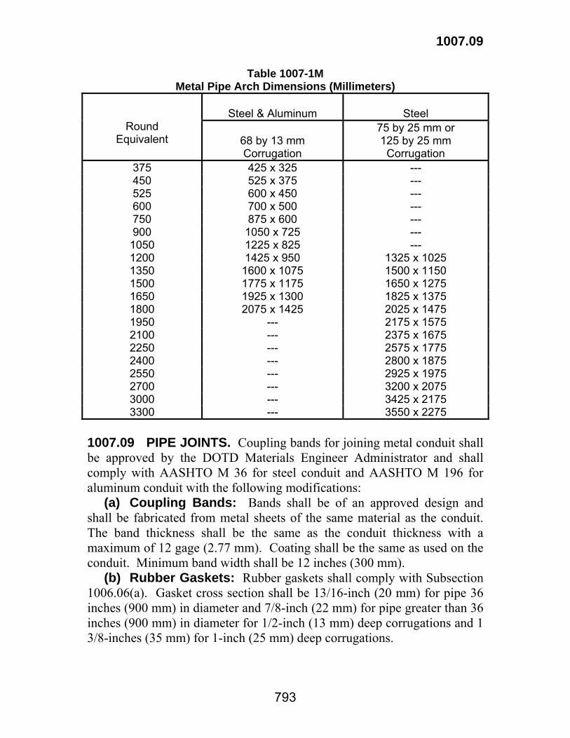
1007.09
793
Table 1007-1M Metal Pipe Arch Dimensions (Millimeters)
Steel & Aluminum
Steel
Round Equivalent
68 by 13 mm Corrugation
75 by 25 mm or 125 by 25 mm
Corrugation 375 425 x 325 --- 450 525 x 375 --- 525 600 x 450 --- 600 700 x 500 --- 750 875 x 600 --- 900 1050 x 725 --- 1050 1225 x 825 --- 1200 1425 x 950 1325 x 1025 1350 1600 x 1075 1500 x 1150 1500 1775 x 1175 1650 x 1275 1650 1925 x 1300 1825 x 1375 1800 2075 x 1425 2025 x 1475 1950 --- 2175 x 1575 2100 --- 2375 x 1675 2250 --- 2575 x 1775 2400 --- 2800 x 1875 2550 --- 2925 x 1975 2700 --- 3200 x 2075 3000 --- 3425 x 2175 3300 --- 3550 x 2275
1007.09 PIPE JOINTS. Coupling bands for joining metal conduit shall be approved by the DOTD Materials Engineer Administrator and shall comply with AASHTO M 36 for steel conduit and AASHTO M 196 for aluminum conduit with the following modifications: (a) Coupling Bands: Bands shall be of an approved design and shall be fabricated from metal sheets of the same material as the conduit. The band thickness shall be the same as the conduit thickness with a maximum of 12 gage (2.77 mm). Coating shall be the same as used on the conduit. Minimum band width shall be 12 inches (300 mm). (b) Rubber Gaskets: Rubber gaskets shall comply with Subsection 1006.06(a). Gasket cross section shall be 13/16-inch (20 mm) for pipe 36 inches (900 mm) in diameter and 7/8-inch (22 mm) for pipe greater than 36 inches (900 mm) in diameter for 1/2-inch (13 mm) deep corrugations and 1 3/8-inches (35 mm) for 1-inch (25 mm) deep corrugations.

1007.09
794
(c) Flexible Plastic Gaskets: Flexible plastic gaskets shall comply with Subsection 1006.06(b). Gasket material shall be a minimum of 1 inch (25 mm) for 1/2-inch (13 mm) corrugation depth, and a minimum of 1 1/2 inches (40 mm) for 1-inch (25 mm) corrugation depth. (d) Hardware: Hardware shall be galvanized in accordance with ASTM A 153 or B 633, Class Fe/Zn 25 or an approved mechanical galvanizing process complying with ASTM B 695 that provides the same coating thickness. (e) Steel Banding Rods: Steel banding rods shall comply with AASHTO M 270, Grade 36 (M 270M, Grade 250). Welding of rods will not be permitted. No more than two splices will be allowed. (f) Type 1 (T1) Joints: These joints shall be soil tight. A Type 2, 3 or other approved joint system may be substituted for a Type 1 joint. At least one line of approved gasket material shall be required under the band on each pipe end. (g) Type 2 (T2) Joints: These joints shall pass the 5 psi hydrostatic pressure test. Joint details shall be as shown on the plans. (h) Type 3 (T3) Joints: These joints shall pass the 10 psi hydrostatic pressure test. Joint details shall be as shown on the plans. 1007.10 CAST IRON SOIL PIPE AND FITTINGS. Cast iron soil pipe and fittings shall comply with ASTM A 74. Joints shall be made with rubber gaskets complying with ASTM C 564. 1007.11 DUCTILE IRON PIPE. Ductile iron pipe shall comply with ANSI A 21.51. 1007.12 BLACK AND GALVANIZED WELDED AND SEAMLESS STEEL PIPE. Steel pipe for ordinary uses shall comply with ASTM A 53.

795
Section 1008 Paints
1008.01 GENERAL. (a) Packaging: Paints shall be delivered in minimum 5-gallon (15 L), full lid, shipping containers complying with Surface Transportation Board (STB) requirements. Used containers will not be permitted unless they have been satisfactorily reconditioned and thoroughly cleaned. (b) Identification: Each paint container shall bear a label with the following information: name and address of manufacturer, trade name or trademark, kind of paint, color of paint, number of liters, batch number and date of production. (c) Storage: After one year from date of manufacture, the material shall not show skinning, settling, color change, thickening or livering that cannot be eliminated by normal mixing procedures. After one year, the paint shall be retested prior to use and shall show no change from when originally approved. No material shall be used after the manufacturer's recommended shelf life. 1008.02 THREE-COAT WATERBORNE PAINT SYSTEM (Two Primers And One Topcoat). The Three-Coat Waterborne Paint System (Two Primers and One Topcoat), shall be an approved system listed on QPL 68. Each system shall be tested for a minimum of 1500 hours in a salt spray (fog) apparatus and fluorescent UV-Condensation Exposure Apparatus in accordance with ASTM B 117 and G 154. The paint system shall show no rusting, checking, cracking, delamination or undercutting. There shall be only slight chalking or discoloration and there shall be no blisters larger than number 8 when rated in accordance with ASTM D 714. Standard X-ray and infrared curves will be made of all approved coatings in accordance with ASTM D 5380 and DOTD TR 610. When the project sample deviates from these curves, the material represented by the sample will be rejected. The following specification is not a formula. The manufacturer assumes all responsibility in formulating products which meet these specification requirements in laboratory testing, field application, and performance. Each paint system shall comply with the following requirements. (a) Primer: (1) System A:
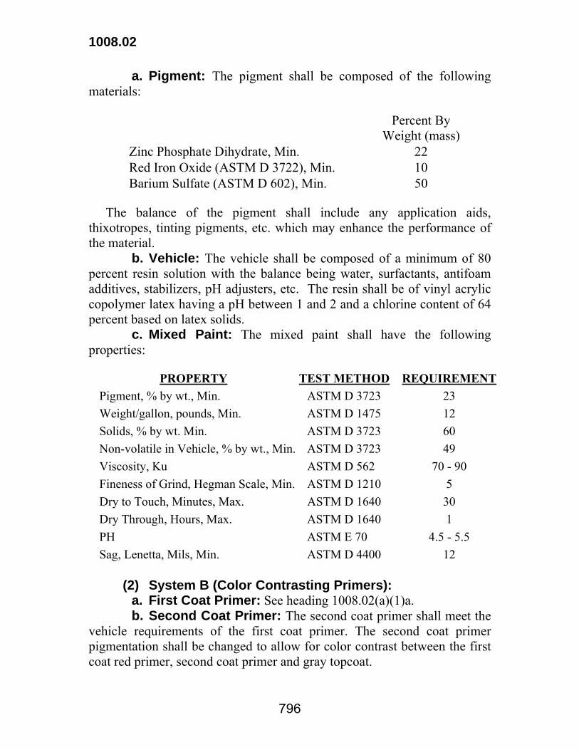
1008.02
796
a. Pigment: The pigment shall be composed of the following materials:
Percent By Weight (mass)
Zinc Phosphate Dihydrate, Min. 22 Red Iron Oxide (ASTM D 3722), Min. 10 Barium Sulfate (ASTM D 602), Min. 50
The balance of the pigment shall include any application aids, thixotropes, tinting pigments, etc. which may enhance the performance of the material. b. Vehicle: The vehicle shall be composed of a minimum of 80 percent resin solution with the balance being water, surfactants, antifoam additives, stabilizers, pH adjusters, etc. The resin shall be of vinyl acrylic copolymer latex having a pH between 1 and 2 and a chlorine content of 64 percent based on latex solids. c. Mixed Paint: The mixed paint shall have the following properties:
PROPERTY TEST METHOD REQUIREMENT Pigment, % by wt., Min. ASTM D 3723 23 Weight/gallon, pounds, Min. ASTM D 1475 12 Solids, % by wt. Min. ASTM D 3723 60 Non-volatile in Vehicle, % by wt., Min. ASTM D 3723 49 Viscosity, Ku ASTM D 562 70 - 90 Fineness of Grind, Hegman Scale, Min. ASTM D 1210 5 Dry to Touch, Minutes, Max. ASTM D 1640 30 Dry Through, Hours, Max. ASTM D 1640 1 PH ASTM E 70 4.5 - 5.5 Sag, Lenetta, Mils, Min. ASTM D 4400 12
(2) System B (Color Contrasting Primers): a. First Coat Primer: See heading 1008.02(a)(1)a. b. Second Coat Primer: The second coat primer shall meet the vehicle requirements of the first coat primer. The second coat primer pigmentation shall be changed to allow for color contrast between the first coat red primer, second coat primer and gray topcoat.
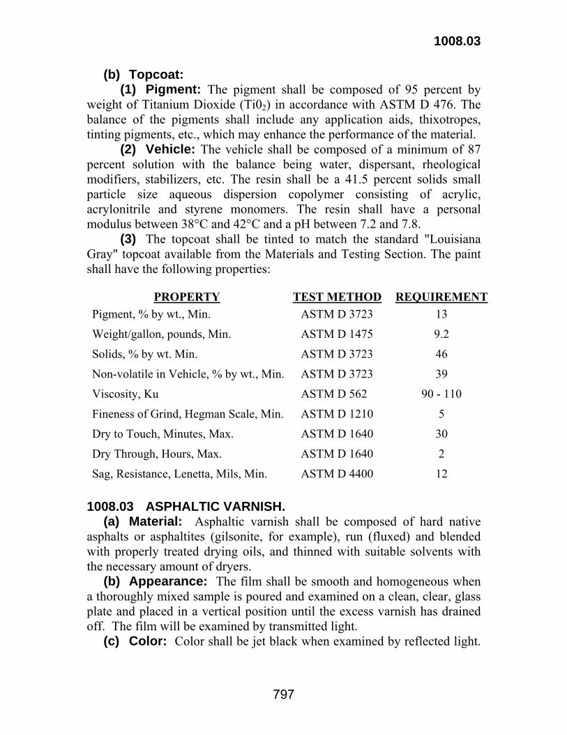
1008.03
797
(b) Topcoat: (1) Pigment: The pigment shall be composed of 95 percent by weight of Titanium Dioxide (Ti02) in accordance with ASTM D 476. The balance of the pigments shall include any application aids, thixotropes, tinting pigments, etc., which may enhance the performance of the material. (2) Vehicle: The vehicle shall be composed of a minimum of 87 percent solution with the balance being water, dispersant, rheological modifiers, stabilizers, etc. The resin shall be a 41.5 percent solids small particle size aqueous dispersion copolymer consisting of acrylic, acrylonitrile and styrene monomers. The resin shall have a personal modulus between 38°C and 42°C and a pH between 7.2 and 7.8. (3) The topcoat shall be tinted to match the standard "Louisiana Gray" topcoat available from the Materials and Testing Section. The paint shall have the following properties:
PROPERTY TEST METHOD REQUIREMENT Pigment, % by wt., Min. ASTM D 3723 13
Weight/gallon, pounds, Min. ASTM D 1475 9.2
Solids, % by wt. Min. ASTM D 3723 46
Non-volatile in Vehicle, % by wt., Min. ASTM D 3723 39
Viscosity, Ku ASTM D 562 90 - 110
Fineness of Grind, Hegman Scale, Min. ASTM D 1210 5
Dry to Touch, Minutes, Max. ASTM D 1640 30
Dry Through, Hours, Max. ASTM D 1640 2
Sag, Resistance, Lenetta, Mils, Min. ASTM D 4400 12 1008.03 ASPHALTIC VARNISH. (a) Material: Asphaltic varnish shall be composed of hard native asphalts or asphaltites (gilsonite, for example), run (fluxed) and blended with properly treated drying oils, and thinned with suitable solvents with the necessary amount of dryers. (b) Appearance: The film shall be smooth and homogeneous when a thoroughly mixed sample is poured and examined on a clean, clear, glass plate and placed in a vertical position until the excess varnish has drained off. The film will be examined by transmitted light. (c) Color: Color shall be jet black when examined by reflected light.
1008.03
798
(d) Nonvolatile Matter: Nonvolatile matter shall be not less than 40 percent by weight (mass) when tested in accordance with ASTM D 2369. (e) Drying of film: (1) Set to Touch: Film shall set to touch in not more than 8 hours when tested in accordance with ASTM D 1640. (2) Dry Through: Film shall dry through in not more than 36 hours when tested in accordance with ASTM D 1640. (f) Working Properties and Appearance of Dried Film: Varnish shall have good brushing, flowing, covering and leveling properties. Dried film shall be jet black, smooth and free from brush marks, blisters, pinholes and other defects. (g) Water Resistance: Film shall show no whitening, dulling or other defects after a dried film is immersed in water for 18 hours and air dried for 2 hours. 1008.04 COAL TAR EPOXY-POLYAMIDE PAINT. This paint shall comply with SSPC Paint No. 16. 1008.05 COLD GALVANIZED REPAIR COMPOUND. This material shall be used for the spot repair of galvanized surfaces and shall be an approved product listed in QPL 23. The material shall be supplied in aerosol cans or friction top cans. The cans shall be labeled with the manufacturer's name, product name, and batch number. The pigment shall contain a minimum of 90 percent metallic zinc. Test panels coated with the compound shall be tested in a salt fog apparatus in accordance with ASTM B 117 for 1500 hours. The panels shall show no sign of rust, blistering, undercutting, delamination, or other deleterious properties when evaluated in accordance with DOTD TR 503. 1008.06 CORROSION INHIBITING ALKYD PAINT SYSTEM. The Corrosion Inhibiting Alkyd Paint System shall be a three-coat paint system applied to properly prepared structural steel surfaces that are permanently exposed to weather. The paint shall be compatible with basic lead silico chromate paint. Either System A or System B can be used, however, whichever system is selected shall be used on the entire project. The corrosion inhibiting pigment in System A shall be zinc hydroxy phosphite and the corrosion inhibiting pigment in System B shall be calcium borosilicate. The primer and the intermediate coats shall be tinted for color contrast. An aluminum topcoat in accordance with AASHTO M69, Type I shall be applied in both systems.

1008.06
799
(a) Specific Requirements: Test methods shall be the latest in effect. The manufacturer assumes all responsibility in formulating products which meet these specifications requirements. Systems A and B shall comply with the following requirements. REQUIREMENT
SYSTEM A SYSTEM B PROPERTY TEST METHOD MIN MAX MIN MAX
PRIMER Pigment, % by wt ASTM D 2371 50 -- 53 -- Vehicle, % by wt ASTM D 2371 -- 50 -- 47 Weight/gallon, pounds @ 77°F ASTM D 1475 12.3 -- 11.4 -- Water, % -- 0.5 -- 0.25 Coarse Particle and Skins (Total Residue Retained on No. 325 Sieve Based on Paint), %
ASTM D 185 -- 1.0 -- 1.0
Fineness of Grind (North Std) ASTM D 1210 5 -- 5 -- Viscosity (Stormer-Krebs Units) @ 77°F
ASTM D 562 70 80 75 85
Dry Through, Hours ASTM D 1640 18 -- 18 -- Non-volatile in Vehicle, % by wt ASTM D 2369 &
ASTM D 2372 66 -- 57 --
REQUIREMENT
PROPERTY TEST METHOD
SYSTEM A MIN MAX
SYSTEM B MIN MAX
INTERMEDIATE COAT Pigment, % by wt ASTM D 2371 50 -- 44 -- Vehicle, % by wt ASTM D 2371 -- 50 -- 56 Weight/gallon, pounds @ 77°F ASTM D 1475 12.3 -- 10.2 -- Water, % -- 0.25 -- 0.25 Coarse Particle and Skins (Total Residue Retained on No. 325 Sieve Based on Paint), % ASTM D 185 -- 1.0 -- 1.0 Fineness of Grind (North Std) ASTM D 1210 5 -- 5 -- Viscosity (Stormer-Krebs Units) @ 77°F
ASTM D 562 70 80 75 85
Dry Through, Hours ASTM D 1640 -- 18 -- 10 Non-volatile in Vehicle, % by wt ASTM D 2369 &
ASTM D 2372 66 -- 45 --
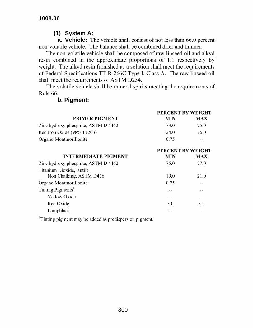
1008.06
800
(1) System A: a. Vehicle: The vehicle shall consist of not less than 66.0 percent non-volatile vehicle. The balance shall be combined drier and thinner. The non-volatile vehicle shall be composed of raw linseed oil and alkyd resin combined in the approximate proportions of 1:1 respectively by weight. The alkyd resin furnished as a solution shall meet the requirements of Federal Specifications TT-R-266C Type I, Class A. The raw linseed oil shall meet the requirements of ASTM D234. The volatile vehicle shall be mineral spirits meeting the requirements of Rule 66. b. Pigment: PERCENT BY WEIGHT
PRIMER PIGMENT MIN MAX Zinc hydroxy phosphite, ASTM D 4462 73.0 75.0 Red Iron Oxide (98% Fe203) 24.0 26.0 Organo Montmorillonite 0.75 --
PERCENT BY WEIGHT INTERMEDIATE PIGMENT MIN MAX
Zinc hydroxy phosphite, ASTM D 4462 75.0 77.0 Titanium Dioxide, Rutile Non Chalking, ASTM D476 19.0 21.0 Organo Montmorillonite 0.75 -- Tinting Pigments1 -- -- Yellow Oxide -- -- Red Oxide 3.0 3.5 Lampblack -- -- 1Tinting pigment may be added as predispersion pigment.

1008.07
801
(2) System B: a. Primer:
PIGMENT MIN MAX
Calcium Boro-Silicate, ASTM D 4288 80.0% -- Synthetic Iron Oxide, ASTM D 84, Class I 16.0% 18.0% Organo Montmorillonite 1.0% 2.0%
VEHICLE
Alkyd Resin Solution, Fed. Spec TT-R-266, Type I, Class A 43.0% 50.0% Linseed Oil, ASTM D 234 20.0% 27.0% Mineral Spirits, Fed. Spec TT-T-291E, Type II1 -- 28.0% Driers 1.0% 2.0% 1 Small quantities of alcohols or alcohol/water mixtures may replace some mineral spirits where such materials are used as polar additives for the suspending aid. b. Intermediate Coat:
PIGMENT MIN MAX
Calcium Boro-Silicate, ASTM D 4288 80.0% -- Synthetic Iron Oxide, ASTM D 84, Class I 17.5% 18.5% Organo Montmorillonite 1.5% 2.5% Lampblack -- 2.0%
VEHICLE Alkyd Resin Solution, Fed. Spec TT-R-266, Type I, Class A 65.0% -- Mineral Spirits, Fed. Spec TT-T-291E, Type II* -- 34.0% Driers 1.0% 1.5%
*Small quantities of alcohols or alcohol/water mixtures may replace some mineral spirits where such materials are used as polar additives for the suspending aid. 1008.07 ZINC PAINT SYSTEMS FOR NEW STRUCTURAL STEEL AND 100 PERCENT BARE EXISTING STRUCTURAL STEEL. The zinc paint system shall be an approved system listed on QPL 78. Each system shall be tested in accordance with AASHTO R 31 and meet the following requirements.

1008.07
802
Zinc Paint Systems
Performance Requirements Inorganic Zinc
Primer
Organic Zinc
Primer Rust Criteria after 5000 hrs exposure to Salt Fog Resistance Test in accordance with ASTM B 117.
Maximum Creep, mm - Evaluated in accordance with AASHTO R 31, Subsection 8.2.2.2. 4 4
Maximum Average Creep, mm - Evaluated in accordance with AASHTO R 31, Subsection 8.2.2.2. 2 2
Maximum length, mm - Evaluated in accordance with AASHTO R 31, Subsection 8.2.2.3. 3 15
Blister Criteria after 4000 hrs exposure to Salt Fog Resistance Test in accordance with ASTM B 117.
Minimum Conversion # - Blistering evaluated in accordance with ASTM D 714. Blister size and frequency converted using blister value conversion table.
8 7
Rust Criteria after 5040 hrs exposure to Cyclic Weathering Resistance Test in accordance with ASTM D 5894.
Maximum Creep, mm - Evaluated in accordance with AASHTO R-31, Subsection 8.2.2.2. 4 12
Maximum Average Creep, (mm) - Evaluated in accordance with AASHTO R 31, Subsection 8.2.2.2. 2 5
Blister Criteria after 4032 hrs exposure to Cyclic Weathering Resistance Test in accordance with ASTM D 5894.
Minimum Conversion # - Blistering evaluated in accordance with ASTM D 714. Blister size and frequency converted using blister value conversion table.
9 8
Adhesion Criteria - Minimum pull-off strength shall be tested in accordance with ASTM D 4541.
Minimum for both primer and PIT (Primer, Intermediate, Topcoat) panels.
(2.4 MPa) 350 psi
(4.1 MPa) 600 psi
Freeze Thaw Criteria – After 30 freeze/thaw cycles as defined in AASHTO R 31, Subsection 8.6.1 there shall be no loss of adhesion when compared with above adhesion results.
Blister Value Conversion Table Blister Frequency
Blister Size Few Medium Medium Dense Dense
#8 9 8 7 6 #6 8 7 6 5 #4 7 6 5 4 #2 6 5 4 3 #1 5 4 3 2
Products to be used on projects will be sampled and tested and shall comply with the following requirements:

1008.07
803
PROPERTY TEST METHOD Specification Acceptance1 Pigment Content. ASTM D 2698 Target Value ±2.0% Density ASTM D 1475 Target Value ±0.25 lbs/gal
(±0.03 kg/l) Solids Content ASTM D 2369 Target Value ±2.0% Non-volatile in Vehicle Content ASTM D 2698 Target Value ±2.0% Viscosity, Ku ASTM D 562 Target Value ±5KU Dry to Touch ASTM D 1640 Target Value ±10% Dry Through ASTM D 1640 Target Value ±10% Sag, Lenetta ASTM D 4400 Target Value ±10% Infrared Spectrum ASTM D 2621 2
X-Ray Diffraction ASTM D 2321 2
1Target Values shall be established by the Materials Section upon qualification of the paint system. 2Standards for infrared spectrum and x-ray diffraction shall be kept on file and compared to project samples for acceptance purposes.
The topcoat shall be tinted to match the standard “Louisiana Gray” topcoat available from the Materials and Testing Section. When weathering steel is used for structural members such as bridge girders, the ends of the members shall be painted with the zinc paint system for a distance of 1.5 times the member depth, not to exceed 10 feet (3 m). The topcoat color shall match the color of the weathered steel.

804
Section 1009 Reinforcing Steel and Wire Rope
1009.01 REINFORCING STEEL. Reinforcing steel for concrete shall comply with the following unless otherwise specified. Reinforcing steel used in bridge superstructures and substructures shall be grade 60 (420). In other structures, deformed bars No. 3 (10) thru No. 6 (19) shall be either Grade 40 (300) or 60 (420); No. 7 (22) and larger shall be Grade 60 (420). Bars smaller than No. 3 (10) need not be deformed. All deformed bars shall comply with Headings (a), (b) or (c) below. Size W 5 wire complying with Heading (d) below may be used in lieu of bars smaller than No. 3 (10). (a) Billet-Steel Deformed and Plain Bars shall comply with ASTM 615 (ASTM A 615M) and shall be an approved product listed on QPL 71. (b) Rail-Steel and Axle-Steel Deformed and Plain Bars shall comply with ASTM A 996 (ASTM A 996M). (c) Cold-Drawn Steel Wire, ASTM A 82 with the following amendment: For material testing over 110,000 psi (760 MPa) tensile strength in high strength applications such as spirals and ties, the 25 percent minimum reduction in area shall be reduced 5 percent for each 10,000 psi (70 MPa) increment of tensile strength exceeding 110,000 psi (760 MPa). (d) Welded Steel Wire Fabric shall conform to ASTM A 185. (e) Epoxy Coated Reinforcing Steel and patching materials shall comply with AASHTO M 284 and shall be approved products listed on QPL 51. 1009.02 SPIRAL REINFORCING. Spiral reinforcing shall comply with Subsection 1009.01(a), (b), (c) or (d). 1009.03 TIE BARS. Tie bars shall comply with Subsection 1009.01 (a), (b) or (c). Tie bars to be bent and restraightened during construction shall be Grade 40 (300). 1009.04 DOWEL BARS. Dowel bars may be placed in approved dowel bar assemblies in accordance with the plans.
1009.08
805
Dowel bars shall be plain steel bars complying with Subsection 1009.01 (a), (b) or (c). Dowels shall have a uniformly round cross section and shall be saw cut, smooth and free of burrs, projections and deformations. Dowel bars shall be undercoated with an adhesive and given an outer coat of polypropylene or polyethylene. The coated dowel bar shall comply with AASHTO M 254. 1009.05 STEEL STRAND FOR PRETENSIONING. Strand for pretensioning shall comply with ASTM A 416. The strand manufacturer shall submit to the Construction Section three copies of Certificates of Analysis of all test results as stipulated in ASTM A 416, and as part of this document, shall provide the modulus of elasticity of that particular mill heat of strand. The Department reserves the right to conduct inspections at the site of manufacture and to have all tests witnessed by its inspector. The data from the manufacturer's typical curve shall be used when computing the required elongation for each strand. 1009.06 BARS FOR POST-TENSIONING. Bars shall be steel complying with ASTM A 722 having a minimum modulus of elasticity of 25,000,000 psi (170,000 MPa), and shall be equipped with wedge-type end anchorages which will develop the minimum specified ultimate bar stress on the nominal bar area. 1009.07 PARALLEL WIRE ASSEMBLIES FOR POST- TENSIONING. Assemblies shall consist of parallel wire of the specified number and size. Wire shall be high tensile strength, hard-drawn, stress-relieved and uncoated, delivered in coils of 54 inches (1350 mm) minimum diameter. Wire shall comply with ASTM A 421, Type WA. 1009.08 ANCHORAGES FOR POST-TENSIONED TENDONS. (a) Bars: Wedge-type anchorages shall be used for bars. Wedge devices shall develop the minimum ultimate stress specified for the nominal bar area. Wedge anchorages shall bear against anchorage plates fabricated of hot-rolled steel having characteristics not less than as specified for No. 1040 of the AISI specifications. (b) Parallel Wire Assemblies: Wedge-type anchorages of the sandwich plate or conical type shall be used. Anchorage device shall be capable of developing the ultimate strength of the total number of wires anchored. Conical-type anchorages shall be embedded within ends of

1009.08
806
concrete members. Anchorages shall bear against embedded grids of reinforcing steel of approved type. (c) Alternate Anchorage Types: Alternate anchorage types complying with the physical requirements specified above for wedge-type anchorages will be considered. Anchorages shall either develop the specified ultimate strength of reinforcing tendons, or the allowable stress on the tendon will be based on anchorage strength. Alternate type anchorages shall show evidence of being capable of withstanding at least 3 million cycles of twice the maximum live load stress variation. 1009.09 ANCHORAGES AND HARDWARE FOR PRETENSIONING. Anchorages, including holddown and miscellaneous hardware, shall be sampled in accordance with the Materials Sampling Manual and submitted to the Construction Section for approval by evaluation or testing. 1009.10 WIRE ROPE. Wire rope shall comply with Federal Specifications RR-W-410D and the following requirements. The type and classification of wire rope shall comply with one shown in Table 1009-1. When wire joints are necessary, they shall be electrically butt-welded; and in the stranding operation, no two joints in any strand shall be closer than 25 feet (7.5 m) apart, except for filler wires.
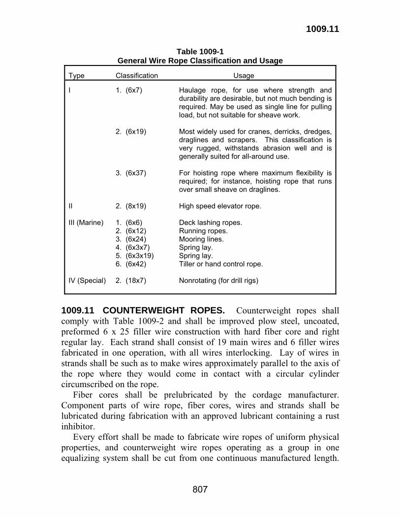
1009.11
807
Table 1009-1 General Wire Rope Classification and Usage
Type Classification Usage I 1. (6x7) Haulage rope, for use where strength and
durability are desirable, but not much bending is required. May be used as single line for pulling load, but not suitable for sheave work.
2. (6x19) Most widely used for cranes, derricks, dredges,
draglines and scrapers. This classification is very rugged, withstands abrasion well and is generally suited for all-around use.
3. (6x37) For hoisting rope where maximum flexibility is
required; for instance, hoisting rope that runs over small sheave on draglines.
II 2. (8x19) High speed elevator rope. III (Marine) 1. (6x6) Deck lashing ropes. 2. (6x12) Running ropes. 3. (6x24) Mooring lines. 4. (6x3x7) Spring lay. 5. (6x3x19) Spring lay. 6. (6x42) Tiller or hand control rope. IV (Special) 2. (18x7) Nonrotating (for drill rigs)
1009.11 COUNTERWEIGHT ROPES. Counterweight ropes shall comply with Table 1009-2 and shall be improved plow steel, uncoated, preformed 6 x 25 filler wire construction with hard fiber core and right regular lay. Each strand shall consist of 19 main wires and 6 filler wires fabricated in one operation, with all wires interlocking. Lay of wires in strands shall be such as to make wires approximately parallel to the axis of the rope where they would come in contact with a circular cylinder circumscribed on the rope. Fiber cores shall be prelubricated by the cordage manufacturer. Component parts of wire rope, fiber cores, wires and strands shall be lubricated during fabrication with an approved lubricant containing a rust inhibitor. Every effort shall be made to fabricate wire ropes of uniform physical properties, and counterweight wire ropes operating as a group in one equalizing system shall be cut from one continuous manufactured length.

1009.11
808
No splicing of wire rope or its component strands will be permitted. Wire from which wire ropes are made shall be tested in the presence of the engineer, except that filler wires may be made to the manufacturer's standards. Wire rope shall be prestressed and measured for length by the manufacturer prior to delivery. The contractor shall notify the engineer at least 10 calendar days in advance of prestressing operations so the Department may have its inspector present for the operations. Counterweight ropes shall be prestressed. The prestressing load shall be 35 percent of the listed breaking strengths of the wire ropes. Loading shall be applied three times to the wire ropes. The cycle of loading shall be between the limits of 5 to 35 percent. The maximum loading shall be held on the wire rope for 15 minutes each. The length of each wire rope from centerline of open socket pins or from the bearing of closed sockets shall be measured under a tension of 12 percent of the listed breaking strengths. A metal tag having the length stamped thereon shall be securely attached to the wire rope. Length of each rope shall also be stamped on each socket. After wire rope has been measured as noted herein, it shall have a stripe painted on one side along its entire length to assure the twist of the wire rope during erection of the bridge. The rope number shall be stamped on each socket, counterweight and span lifting point. While being measured, each rope shall be twisted to correct lay and shall be supported throughout its length in a straight line at maximum 25-foot (7.6 m) intervals. Lengths of wire rope in excess of 100 feet (30 m) shall not vary from specified length by more than 0.0002 times the specified length. For wire rope lengths of 100 feet (30 m) or less, the tolerance from specified length shall be ±1/4 inch (±5 mm). Sockets and socket pins used with wire ropes shall be forged, without welds, from solid steel and shall conform to ASTM A 688, Class D, normalized except that sockets for ropes 2 1/2 inches (63 mm) or greater diameter may be cast steel conforming to ASTM A 148, Grade 80-50. The socket shall be attached to the wire rope by using zinc of a quality not less than defined for Intermediate Grade in ASTM B 6. Wire rope shall not slip appreciably in its connection. Full-sized specimens of rope shall be fitted with sockets, attached not less than 25 rope diameters but not more than 12 feet (3.6 m) apart, and shall be tested to destruction. Sockets used for these tests shall not be used in the structure.
1009.11
809
Movement of the zinc cone in the socket basket when the wire rope is stressed to 80 percent of listed breaking strength shall not exceed 1/6 the nominal diameter of the wire rope. If a greater movement occurs, the method of attachment shall be changed until a satisfactory method is found. The number of test specimens shall not exceed 10 percent of the total number of finished lengths of rope to be made, nor shall there be less than two specimens taken from each original length of rope. The manufacturer shall provide proper facilities for making the tests and shall make them at no direct pay. The contractor shall furnish the engineer with certified test reports for all required tests. If a socket breaks during tests of the wire rope, two other sockets shall be selected and attached to another piece of rope, and the test repeated. This process shall be continued until reliability of the sockets is established, in which case the lot shall be accepted. If, however, 10 percent or more of the sockets tested break at a load less than the specified minimum strength of the rope, the entire lot will be rejected. The engineer reserves the right to test each wire rope at the Department's expense after sockets are attached, by a load equal to 1/2 the listed breaking strength of the wire rope. If the assembly shows weakness, it will be rejected and replaced. Wire ropes shall be suitably marked or tagged for identification for proper erection. Wire rope shall be shipped on reels or in coils. The minimum reel diameter or the inside diameter of coils shall not be less than 25 times the minimum diameter of the wire rope. Wire ropes shipped on reels shall be removed by revolving the reels, and wire ropes shipped in coils shall be mounted on a turntable for uncoiling. In uncoiling and erecting, wire ropes shall be carefully handled to avoid kinks, sharp bends or twisting.

810
Table 1009-2 Counterweight Rope
Rope Diameter
Minimum,
Maximum,
Approximate Circumference,
Maximum Strand Pitch,
Approximate Weight (mass),
Minimum Breaking Strength on Bright
(Uncoated) Wire Ropes
in. mm in. mm in. mm in. mm lb/ft kg/m lb. kg 1/4 5/16 3/8 7/16 1/2 9/16 5/8 3/4 7/8 1 1 1/8 1 1/4 1 3/8 1 1/2 1 5/8 1 3/4 1 7/8 2 2 1/8 2 1/4 2 1/2 2 3/4
6.0 7.5 9.5 11 12.5 14 15.5 19 22 25 28.5 32 34.5 38 41 44.5 47.5 50.5 54 57 63 70
9/32 11/32 13/32 15/32 17/32 19/32 21/32 25/32 59/64 1 3/64 1 11/64 1 5/16 1 7/16 1 9/16 1 23/32 1 27/32 1 31/32 2 3/32 2 7/32 2 11/32 2 5/8 2 7/8
7 9 10.5 12 13.5 15 17 20 23.5 27 30 33.5 36.5 40 44 47 50 53.5 56.5 60 67 73
3/4 1 1 1/8 1 3/8 1 5/8 1 3/4 2 2 3/8 2 3/4 3 1/8 3 1/2 3 7/8 4 3/8 4 3/4 5 1/8 5 1/2 5 7/8 6 1/4 6 5/8 7 1/8 7 7/8 8 5/8
20 25 30 35 40 45 50 60 70 80 90 100 110 120 130 140 150 160 170 180 200 220
1 11/16 2 1/8 2 17/32 2 31/32 3 3/8 3 13/16 4 7/32 5 1/16 5 29/32 6 3/4 7 19/32 8 7/16 9 9/32 10 1/8 10 31/32 11 13/16 12 21/32 13 1/2 14 11/32 15 3/16 16 7/8 18 9/16
43 54 64 75 86 97 107 129 150 171 193 214 236 257 279 300 322 343 364 386 429 472
0.105 0.164 0.236 0.32 0.42 0.53 0.66 0.95 1.29 1.68 2.13 2.63 3.18 3.78 4.44 5.15 5.91 6.72 7.59 8.51 10.5 12.7
0.156 0.244 0.351 0.48 0.63 0.79 0.98 1.41 1.92 2.50 3.17 3.91 4.73 5.63 6.61 7.66 8.80 10.00 11.30 12.66 15.6 18.9
5,343 8,307 11,895 16,127 20,865 26,325 32,565 46,410 62,790 81,510 102,570 125,970 151,515 179,400 208,650 241,800 274,950 312,000 349,050 390,000 475,800 569,400
2 424 3 768 5 396 7 315 9 464 11 941 14 771 21 050 28 480 36 970 46 525 57 140 68 725 81 370 94 640 109 680 124 720 141 500 158 350 176 900 215 800 258 300
811
Section 1010 Fence and Guard Rail
1010.01 BARBED WIRE. Barbed wire shall be either steel or aluminum alloy and shall be 12 1/2 gage (2.5 mm diameter). (a) Steel Barbed Wire: Steel barbed wire shall comply with ASTM A 121. (b) Aluminum Alloy Barbed Wire: Aluminum alloy barbed wire shall comply with ASTM B 211, Alloy 5052-0 for line wire and Alloy 5052-H38 for barbs. 1010.02 WOVEN WIRE. Woven wire shall comply with one of the following Design Numbers and Grades of ASTM A 116.
Design No.
Grade
939-6-11 939-6-12 1/2939-6-14 1/2939-6-12 1/2
60 60
125 125
1010.03 POSTS AND BRACES FOR FIELD AND LINE TYPE FENCE. Posts and braces shall be either steel or treated timber. (a) Treated Timber Posts and Braces: Braces shall be either round or square. Posts shall be round. Treated timber posts and braces shall comply with Section 1014. (b) Steel Posts and Braces: Steel posts and braces shall be equipped with corrugations, knobs, notches, holes or studs so placed and constructed as to engage a substantial number of fence wires in proper position. Posts may be punched with holes in such position and of such size as will not unduly impair the strength of the posts. Posts with punched tabs used for fastening wires are not acceptable. Corner, end and bracing posts shall be supplied with necessary holes and with galvanized bolts of standard commercial quality or other satisfactory substitute, such as castings, for fastening braces to the posts. Line posts, anchor plates and braces shall comply with ASTM A 702, except that a hardness test may not be substituted for the tensile test. Steel posts, anchor plates and braces shall be galvanized in accordance with ASTM A 123.
1010.04
812
1010.04 STAPLES AND NAILS. Staples and nails shall be made of galvanized steel wire. Minimum galvanized coating shall be not less than 0.20 ounce per square foot (60 g/sq m) when tested in accordance with ASTM A 90. 1010.05 METAL FASTENERS FOR STEEL POSTS. Metal fasteners for steel posts shall be galvanized steel-wire fasteners or clamps and shall be satisfactory for use with the type of steel post furnished. Wire shall be not less than 0.120 inch (3.0 mm) diameter. Galvanized coating shall not be less than 0.20 ounce per square foot (60 g/sq m) when tested in accordance with ASTM A 90. 1010.06 GATES FOR FIELD AND LINE TYPE FENCE. (a) Gates: Steel used in fabricating gates shall be galvanized in accordance with ASTM A 653 Coating Designation G60 (A653M Coating Designation Z180). (b) Posts: (1) Treated Timber: Treated timber posts shall comply with Section 1014. (2) Metal: Metal posts shall be made of galvanized steel pipe, standard weight, complying with ASTM A 53. (c) Hardware: Hinges, washers, nails, staples, welded chains and latches shall be galvanized, of acceptable quality, and of satisfactory type for use with the gate and posts selected. (d) Gate Stops: (1) Treated Timber: Gate stops shall be timber complying with Subsection 1010.03(a) treated in the same manner as posts. (2) Metal: Gate stops shall be acceptable galvanized steel suitable for welding to the post. (e) Stop Posts: Stop posts for double swinging driveway gates shall be treated timber complying with Section 1014. 1010.07 CHAIN LINK FENCE, GATES AND APPURTENANCES. Materials shall comply with AASHTO M 181 except for the following. (a) Wire ties, fabric ties, hog rings and tension wire for Type I, II or III fencing shall be either aluminum alloy, galvanized ductile steel or aluminum-coated ductile steel wire. (1) Wire Ties: Wire ties, fabric ties and hog rings shall have 20,000 psi (140 MPa) minimum tensile strength, and 10 percent minimum elongation. Steel shall be coated with at least 0.60 ounce (180 g) of zinc or

1010.09
813
0.40 ounce (120 g) of aluminum alloy per square foot (sq m) of uncoated wire surface. Wire ties shall be AWG No. 9 (6.60 sq mm). Fabric ties and hog rings shall be AWG No. 12 (3.31 sq mm). (2) Tension Wire: a. Galvanized and aluminum-coated steel tension wire shall be AWG No. 9 (6.60 sq mm) wire having at least 75,000 psi (515 MPa) tensile strength with at least 0.70 ounce (210 g) of zinc or 0.40 ounce (120 g) of aluminum alloy per square foot of uncoated wire surface. b. Aluminum alloy tension wire shall be AWG No. 6 (13.30 sq mm) wire having at least 42,000 psi (290 MPa) tensile strength, 35,000 psi (240 MPa) yield strength, and 10 percent elongation. (b) Barbed wire used with chain link fence shall comply with Subsection 1010.01. (c) Padlocks shall be solid jacket, extruded brass metal with interchangeable cores and 1 3/4-inches (45 mm) cases. All padlocks shall be keyed alike. Two keys shall be furnished for each padlock. 1010.08 METAL BEAM FOR HIGHWAY GUARD RAIL. Rail elements shall be corrugated sheet steel beams from a source shown on QPL 81. Guard rail elements, terminal sections and fittings shall be interchangeable with similar parts, regardless of source or manufacturer. Guard rail, terminal sections and appurtenances shall comply with AASHTO M 180. The fabricator shall annually file a Brand Registration and Guarantee with the DOTD Materials Engineer Administrator in accordance with AASHTO M 180. 1010.09 GUARD RAIL POSTS AND SPACER BLOCKS. Railing posts shall be either timber or steel. When the choice of post is at the option of the contractor, there shall be only one kind furnished on the project. Spacer blocks shall be timber or an alternate material approved based upon results of NCHRP 350. (a) Timber Posts and Spacer Blocks: Timber and treatment shall comply with Section 1014. (b) Steel Posts: Steel posts and shall conform to AASHTO M 270, Grade 36 (M 270M, Grade 250) or ASTM A 769, Grade 40 (A 769M, Grade 275) galvanized in accordance with ASTM A 123. Certificates of Analysis (Mill Test Reports) together with a Fabricator's Material Statement and Certificate of Compliance shall be furnished in accordance

1010.09
814
with Subsection 1013.01. Welding, if required, shall be in accordance with Section 815. (c) Concrete for anchorages shall comply with Section 901 Class M. Reinforcement for anchorages shall comply with Section 1009. 1010.10 GUARD RAIL HARDWARE. Splices, end connections, anchor rods and accessories shall be of such strength as to develop the full design strength of the rail elements. Bolts shall comply with ASTM A 307 and nuts shall comply with ASTM A 563, Grade A (A563M, Property Class 5). Fittings, bolts, washers and other accessories for steel guard rail shall be galvanized after fabrication in accordance with ASTM A 123 or A 153, or by an approved mechanical galvanizing process complying with ASTM B 695 that provides the same coating thickness. All galvanizing shall be done after fabrication. 1010.11 WIRE ROPE AND FITTINGS FOR HIGHWAY GUARD RAIL. Wire rope or wire cable and fittings shall comply with AASHTO M 30.
815
Section 1011 Concrete Curing Materials,
Admixtures and Special Finishes 1011.01 CURING MATERIALS. (a) Liquid Membrane-Forming Compounds: This material shall comply with AASHTO M 148 and be an approved product listed in QPL 65. The types shall be Type 2 white-pigmented or Type 1-D, clear or translucent with a fugitive dye, as specified. (b) Burlap Cloth made from Jute or Kenaf shall comply with AASHTO M 182, Class 3. (c) Waterproof Paper shall comply with AASHTO M 171. (d) White Polyethylene Sheeting shall comply with AASHTO M 171. (e) Combined Burlap and White Polyethylene Sheeting shall comply with AASHTO M 171. 1011.02 ADMIXTURES. (a) Physical Requirements: Concrete admixtures shall be an approved product listed in QPL 58 and shall comply with the requirements in Table 1011-1 when tested in accordance with DOTD TR 224. (b) Chemical Requirements: Unless a chloride type admixture is specified, the contribution of chloride ion resulting from the addition of admixtures to the concrete shall not exceed 0.02 pound per cubic yard (12 g/cu m) of concrete, when tested in accordance with DOTD TR 643. (c) Acceptance Testing: The admixture shall be tested by analytical infrared (IR) spectroscopy in accordance with DOTD TR 610. The percent solids by weight (mass) shall be determined in accordance with DOTD TR 524. The IR spectrum shall compare favorably to the standard IR spectrum of the original material tested and listed in QPL 58. The percent solids content shall not deviate more than ±10 percent from that of the original approved material which was determined by the Materials and Testing Section. Tests to determine rate of hardening, compressive strength or other properties may be made at any time during the work to ensure continued compliance with these specifications. 1011.03 SPECIAL SURFACE FINISH FOR CONCRETE. This material shall be an approved product listed in QPL 14 and comply with

1011.03
816
established tolerances. The material shall provide a uniform, fine-textured finish complying with these specifications. Method and rate of application shall be as recommended by the manufacturer, except that application rate shall not exceed 60 square feet per mixed gallon (1.5 sq m per mixed L). The material shall consist of a water-based one-component coating system containing pigments, texturizers, resins and water, and shall be supplied in containers not smaller than 5 gallons (15 L). The coating shall contain fungicides to adequately prevent the growth of mildew, mold, etc. No field additions to the coating will be permitted. When tested in accordance with the QPL 14 Qualification Procedure, DOTD TR 620, the material shall comply with the following requirements: (a) The average number of cycles to failure shall be not less than 50 cycles when tested in accordance with ASTM C 666. Test specimens shall show no flaking, cracking, spalling or loss of bond. (b) The material shall be unaffected except for slight chalking or discoloration when exposed to 1000 hours of accelerated weathering using UV-B lamps in accordance with ASTM G 154. (c) Color and texture of the material when applied to the test panel shall closely match that of the standard "Louisiana Gray" color chip on file at the Materials and Testing Section.

817
Table 1011-1 Physical Requirements for Admixtures
Water-Reducing
High Range Water Reducing
Property
Test Method Air Entraining
Normal Set
Set Retarding
Normal Set
Set Retarding
Set
Accelerating
Unit Water Content, Max. % of Control Min. % of Control Air Content, %, Total
DOTD TR 202
90 ---
5 ± 1
95 89
0 to 3
95 89
0 to 3
88 ---
0 to 3
88 to
0 to 3
--- ---
0 to 3 Time of Setting, allowable deviation from control, hr:min. Initial: at least
not more than Final: at least
not more than Compressive Strength, Min. % of Control
1 Day 3 Days 7 Days 28 Days 6 Months 1 year
Flexural Strength, Min. % of Control
3 Days 7 Days 28 Days
Relative Durability Factor, Min. % of Control
AASHTO T 197
DOTD TR 230
AASHTO T 97
AASHTO T 161
--- ---
--- ---
--- --- 85 85 --- ---
--- --- ---
---
--- 1:00 earlier or 1:30 later
--- 1:00 earlier or 1:30 later
--- ---
105 105 --- ---
--- --- ---
---
1:30 later 3:30 later
---
3:30 later
--- ---
105 105 --- ---
--- --- ---
---
--- 1:00 earlier or 1:30 later
--- 1:00 earlier or 1:30 later
140 125 115 110 100 100
110 100 100
100
1:30 later 3:30 later
---
3:30 later
125 125 115 110 100 100
110 100 100
100
1:00 earlier 3:30 earler
1:00 earlier
---
125 100 100 100 --- ---
--- 100 100
100

818
Section 1012 Bridge Railings and Barriers
1012.01 CONCRETE. Concrete for bridge railings and barriers shall be Class AA complying with Section 901. 1012.02 REINFORCING STEEL. Reinforcing steel shall be deformed bars complying with Subsection 1009.01. 1012.03 STRUCTURAL STEEL. Structural steel for railings and railing posts shall be AASHTO M 270, Grade 36 steel complying with Subsection 1013.01, except that the maximum tensile strength requirement will be waived. 1012.04 GALVANIZED STEEL PIPE RAILINGS. (a) Galvanized Steel Pipe: Galvanized steel pipe shall be standard weight complying with ASTM A 53. (b) Fittings and Castings: Fittings and castings for steel pipe shall be malleable iron or cast steel complying with ASTM A 47, Grade 32510 or A 27, Grade 70-36. Fittings and castings shall be galvanized in accordance with ASTM A 153. Repairs to galvanized surfaces shall be made in accordance with Subsection 811.12. Three copies of Certificates of Analysis giving chemical and physical test results shall be forwarded for approval to the Construction Section for each heat or foundry pour of iron or steel post castings, with Certificates of Compliance as to the ounces per square foot (g/sq m) of galvanized coating applied. (c) Bolts, Nuts and Washers: High strength bolts shall comply with ASTM A 325 (A 325 M). Bolts, nuts and washers shall be galvanized in accordance with ASTM A 153 or by an approved mechanical galvanizing process complying with ASTM B 695 that provides the same coating thickness. High strength nuts and washers shall comply with Subsection 1013.08(b). When high strength bolts are not required, bolts shall comply with ASTM A 307 Grade A, and nuts shall comply with ASTM A 563. Unless otherwise specified, any appropriate steel washers can be used and the coating must be similar to the bolts and nuts.
1012.04
819
(d) Screws: Machine screws for fastening access door covers to railing posts, and socket head cup point set screws for fastening pipe rail to railing posts and pipe caps to railing, shall be stainless steel and furnished by the supplier.

820
Section 1013 Metals
1013.01 STRUCTURAL STEEL. The contractor shall obtain all applicable physical and chemical tests and furnish the Construction Section five copies of the Certificates of Analysis (Mill Test Reports) together with a Fabricator's Material Statement and Certificate of Compliance. This form will be furnished by the Department upon request. Structural steel shall comply with AASHTO M 270 (M 270M) specifications. Longitudinal Charpy V-Notch Testing: When specified, the main load-carrying structural member components that are subject to tensile stress shall meet the longitudinal Charpy V-Notch requirements contained in the AASHTO M 270 (M 270M) Supplemental Requirements for Non-Fracture Critical Impact Test Requirements and for Fracture Critical Impact Test Requirements. Sampling and testing procedures shall be in accordance with AASHTO T 243 (T 243M) and AASHTO T 244 and the following requirements: the (H) frequency of heat testing shall be used for all steels except that for AASHTO M 270, Grade 100 (M 270M, Grade 690) steel the (P) frequency of piece testing shall be used. 1013.02 RIVET STEEL. (a) Structural Rivet Steel shall comply with ASTM A 502, Grade 1. (b) High Strength Rivet Steel shall comply with ASTM A 502, Grade 2. 1013.03 COPPER BEARING STEEL. When copper bearing steel is specified, the steel shall contain at least 0.2 percent copper. 1013.04 STEEL FORGINGS AND STEEL SHAFTING. (a) Carbon and Alloy Steel Forgings: Steel forgings shall comply with ASTM A 668 (ASTM A 668M). Class C forgings shall be furnished except in cases specified below: (1) Forged Shafts: Forged shafts shall comply with ASTM A 668 (ASTM A 668M), Class F. (2) Forged Trunnions: Forged trunnions shall comply with ASTM A 668 (ASTM A 668M), Class G.

1013.08
821
(b) Alloy Steel Forgings for Pinions and Reduction Gears: Alloy steel forgings for pinions and reduction gears shall comply with ASTM A 291, Class 3 or 3A. (c) Cold Finished Steel Shafting: Cold finished carbon steel shafting shall comply with ASTM A 108. Cold finished alloy steel shafting shall comply with ASTM A 331. 1013.05 STEEL CASTINGS. (a) Steel castings for highway bridges shall comply with ASTM A 27, Grade 70-36 (ASTM A 27M, Grade 485-250). (b) High strength steel castings shall comply with ASTM A 148 (ASTM A 148M). (c) Chromium alloy steel castings shall comply with ASTM A 743 (ASTM A 743M), Grade CA-15. 1013.06 CASTINGS. Castings shall be true to pattern in form and dimensions and free from pouring faults, sponginess, cracks, blowholes and other defects in positions affecting their strength and value for the service intended. Castings shall be boldly filleted at angles, and rises shall be sharp and perfect. Castings shall be sandblasted or otherwise effectively cleaned of scale and sanded to a smooth, clean and uniform surface. (a) Gray Iron Castings shall comply with AASHTO M 306. (b) Malleable Castings shall comply with ASTM A 47, Grade 32510. (ASTM A 47M, Grade 22010). (c) Ductile Iron Castings shall comply with ASTM A 536, Grade 60-40-18. Castings weighing more than 1,000 pounds (450 kg) shall be ultrasonically tested for voids. If voids are found, the casting will be rejected. 1013.07 BRONZE OR COPPER ALLOY BEARING AND EXPANSION PLATES. (a) Bronze Bearing and Expansion Plates shall comply with ASTM B 22, Alloy C 91100. (b) Rolled Copper-Alloy Bearing and Expansion Plates shall comply with ASTM B 100, Alloy C 51000. 1013.08 BOLTS, NUTS AND WASHERS. (a) Carbon Steel Bolts, Nuts, and Washers: When high strength bolts are not required, bolts shall comply with ASTM A 307 Grade A, and nuts shall comply with ASTM A 563. Unless otherwise specified,

1013.08
822
any appropriate steel washers can be used and the coating must be similar to the bolts and nuts. (b) High Strength Bolts, Nuts and Circular Washers: Bolts, nuts and washers shall have plain surface finish unless otherwise specified. (1) High strength bolts shall comply with ASTM A 325 (ASTM A 325M) or ASTM A 490 (ASTM A 490M), as specified. For ASTM A 325 (ASTM A 325M) bolts, Type 1 bolts shall be used; except that Type 3 bolts shall be used with unpainted AASHTO M 270, Grade 50W (M 270M, Grade 345W) steel. (2) For Type 1 bolts, the nuts shall comply with ASTM A 563, Grade DH (ASTM A 563M, Property Class 12) or ASTM A 194 (ASTM A 194M), Grade 2H. For Type 3 bolts, the nuts shall comply with ASTM A 563, Grade DH3 (ASTM A 563M, Property Class 12). (3) Circular washers for high strength bolts shall comply with ASTM F 436 (ASTM F 436M). (c) Lock-Pin and Collar Fasteners: Subject to approval, high strength steel lock-pin and collar fasteners, including washers, may be used as an alternate for high strength bolts or rivets. Shank and head of high strength steel lock-pin and collar fasteners shall meet the chemical and mechanical requirements of ASTM A 325 (ASTM A 325M) or ASTM A 490 (ASTM A 490M), as specified. Each fastener shall provide a solid shank body of sufficient diameter to provide tensile and shear strength equivalent to the bolt or rivet specified. Each fastener shall have a cold-forged head on one end of approved type and dimensions, a shank length suitable for material thickness fastening and locking grooves, breakneck groove, and pull grooves (all annular grooves) on the opposite end. Each fastener shall provide a steel locking collar of proper size for the shank diameter used, which by suitable installation tools, is cold-swaged into the locking grooves forming a head for the grooved end of the fastener after the pull groove section has been removed. The steel locking collar shall be a standard product of an established manufacturer of lock-pin and collar fasteners. 1013.09 STEEL PILES. Steel piles shall comply with AASHTO M 270, Grade 36 (M 270M, Grade 250). 1013.10 SHEET PILES. Steel sheet piles shall comply with ASTM A 328 (ASTM A 328M). Aluminum sheet piles shall comply with ASTM B 221 (ASTM B 221M), Alloy 6061-T6 or Alloy 6063-T6 or ASTM B 209 (ASTM B 209M) Alloy 3064-H34.

1013.20
823
1013.11 STEEL PIPE PILES. Steel pipe piles shall comply with ASTM A 252, Grade 2. 1013.12 SHEET COPPER. Sheet copper shall comply with ASTM B 152. 1013.13 SHEET LEAD. Sheet lead shall comply with ASTM B 29. 1013.14 SHEET ZINC. Sheet zinc shall comply with ASTM B 69, Type II. 1013.15 COLD-ROLLED STEEL. Cold-rolled steel shall be cold-finished steel complying with ASTM A 108. 1013.16 BRONZE. (a) Center discs for movable bridges shall comply with ASTM B 22, Alloy C91300. (b) Trunnion and similar bearings for movable bridges shall comply with ASTM B 22, Alloy C91100. (c) Shafts and ordinary bearings shall comply with ASTM B 22, Alloy C90500. (d) Gears, nuts transmitting motion, and other parts involving stresses other than compression shall comply with ASTM B 22, Alloy C90500. 1013.17 BABBITT METAL. Babbitt Metal shall comply with ASTM B 23, Alloy 3. 1013.18 STEEL FOR CENTER DISCS (Movable Bridges). Steel for center discs shall comply with ASTM A 668 (ASTM A 668M), Class F. 1013.19 STEEL FOR KEYS (Movable Bridges). Steel for keys shall comply with Subsection 1013.15 or ASTM A 668 (ASTM A 668M), Class D. 1013.20 SEAMLESS STEEL PIPE AND TUBING FOR HYDRAULIC LINES. Carbon steel pipe for hydraulic lines shall comply with ASTM A 106, Grade B. Fittings for hydraulic lines shall comply with ASTM A 105 (ASTM A 105M). Stainless steel tubing shall be seamless austenitic stainless steel and shall comply with ASTM A 269.
1013.21
824
1013.21 STEEL FOR OPEN GRID BRIDGE FLOORING. Steel shall comply with Subsection 1013.01. 1013.22 DUCTILE CAST IRON BEARINGS. Ductile cast iron bearings shall comply with ASTM A 536. 1013.23 SHEAR CONNECTORS. Shear connector studs shall be Type B studs complying with ANSI/AASHTO/AWS D 1.5 (D 1.5M), Bridge Welding Code. 1013.24 CONCRETE ANCHOR STUDS. Concrete anchor studs used for end dam plates, bearing plates or other concrete anchorage shall be Type A Studs complying with the latest edition of ANSI/AASHTO/AWS D1.5- (D 1.5M), Bridge Welding Code. 1013.25 STEEL FOR STAY-IN-PLACE FORMS. Zinc-coated steel sheets shall comply with ASTM A 653 with a minimum G 165 coating.

825
Section 1014 Timber and Timber Preservatives
1014.01 STRUCTURAL TIMBER AND LUMBER. Species and grade of structural timber and lumber shall comply with AASHTO M 168 and the following requirements. (a) Southern Pine: Referring to the latest Standard Grading Rules for Southern Pine Lumber, as published by the Southern Pine Inspection Bureau (SPIB), Southern Pine lumber shall be furnished in grades with definite unit working stresses assigned as indicated for grade of lumber required. (1) Caps, stringers, decking and bridge rails shall be Grade No. 1 Dense SR Timbers. (2) Items other than caps, stringers, decking and bridge rail shall be Grade No. 1 SR Timbers. (b) Douglas Fir: Referring to the latest Standard Grading Rules for Western Lumber, Douglas Fir lumber shall be furnished in accordance with the following: (1) Caps, stringers, decking and bridge rail shall comply with Section 70.10, Select Structural. Design values shall be in accordance with Table 4, page 176, "Recommended Design Values in Pounds Per Square Inch". (2) Items other than caps, stringers, decking and bridge rail shall conform to Section 70.11, Grade 1. Design values shall be in accordance with Table 4, page 176, "Recommended Design Values in Pounds Per Square Inch". 1014.02 TIMBER PILES, POLES, POSTS AND BRACES. (a) Timber Piles: Timber piles shall be Southern Yellow Pine or Douglas Fir and shall comply with ASTM D 25, except that Table 1014-1 herein shall be used in lieu of Tables I and II in ASTM D 25. (b) Timber Poles: Timber poles shall be Southern Pine or Douglas Fir and shall comply with ANSI D 05.1. (c) Timber Posts and Braces: Posts and braces shall be cut from sound trees (not limbs) and shall contain no unsound knots. Sound knots will be permitted if the diameter of the knot does not exceed 1/3 the diameter of the piece at the point where it occurs. Posts and braces shall be free from decayed wood, rot and red heart. Ring shakes and season checks

1014.02
826
which penetrate more than 1/4 inch (6 mm) will be cause for rejection. Posts and braces shall show at least four annular rings per inch (25 mm) and at least 1/3 summer wood. Fence posts shall be peeled for their full length and bark and inner skin removed. Knots shall be trimmed close to the body of the post before treatment. A line drawn from center of top to center of butt shall not fall outside the body of the posts nor at any point be more than 2 inches (50 mm) from the geometric center of the post. Posts and braces shall be free from short or reverse bends. Excessive bow, camber, twist or other such defects in posts and brace will be cause for rejection. Ends shall be sawed square. Guard rail posts and spacer blocks shall be treated timber of Southern Pine Grade No. 1 S.R. or Douglas Fir Dense Construction quality. Posts and spacer blocks shall be fabricated before treatment. When round timber posts are specified or shown in the plans for guard rail, the posts shall be 7 1/4 inches (184 mm) in diameter plus or minus 1/8 inch (3 mm) at any point, as determined by a circumference-diameter tape. The length of the post shall be 6 feet-3 inches (1.875 m) for W-Beam and 6 feet-9 inches (2 m) for thrie beam guard rail and shall not vary more than 1 inch (25 mm) in length. The round timber post top shall be domed approximately hemispherical in shape and the radius of the dome shall be 4 inches (100 mm). The dome shall be smooth, and the distance from the top of the dome to the base of the dome shall not vary more than 3/4 inch (19 mm) at any location. All round timber posts shall be smooth shaved by machine and no "ringing" will be permitted. All outer and inner bark shall be removed during the shaving process. All knots and knobs shall be trimmed smooth and flush with the surface of the post. Each post shall have minimum sapwood depth of 1 inch (25 mm) measured at any location within the circumference. The maximum diameter of any single knot shall not exceed 3 inches (75 mm). The sum of the diameters of all knots greater than 0.5 inch (13 mm) in any 1-foot (300 mm) section shall not exceed 8 inches (200 mm). A straight line drawn from the center of the top to the center of the butt of any post shall not deviate from the centerline of the post more than 1/4 inch (6 mm) at any point. Splits or ring shakes are not permitted in the top for round post. Splits are not permitted in the butt. A single shake is permitted in the butt, provided it is not wider than one half the butt diameter. Guard rail timber species (spacer blocks/braces) shall be the same as those furnished for the timber posts. The actual finished size of spacer blocks for round timber posts shall be 5 3/4 inch square (146 mm), with a

1014.03
827
tolerance of 1/8 inch (3 mm) plus or minus. Each of the four corners of each block shall be machined down to provide a flat 1 inch (25 mm) surface the entire length of the block with a tolerance of 1/4 inch (6 mm) plus or minus. Each block shall be machine concaved to a radius of 3 5/8 inches (92 mm), and to a depth of 3/4 inch (18 mm). The size and hole location shall be as shown on the plans. Spacers shall be of medium grain, at least 4 rings per inch, and free from splits, shakes, compression wood or decay in any form. Individual knots, knot clusters or knots in the same cross section of a face are permitted, provided they are sound or firm, and are limited in cumulative width (when measured between lines paralleled to the edges) to no more than one third the width of the face. Grain deviation is limited to 1 inch (25 mm) in 6 inches (150 mm). The material may be sawn or surfaced.
Table 1014-1 Circumferences and Diameters of Timber Pile1
3 Feet from Butt, inches (mm) At Tip, inches (mm) Minimum Maximum Minimum
Length, feet (m)
Circumference Diameter(Approx.)
Circumference
Diameter(Approx.)
Circumference
Diameter(Approx.)
Under 40 (12.2) 40 to 54 Incl. (12.2-16.4) 55 to 74 Incl. (16.5-22.6) 75 to 90 Incl. (22.7-27.4) Over 90 (27.4)
38
(960) 38
(960) 41
(1040) 41
(1040) 41
(1040)
12
(300) 12
(300) 13
(330) 13
(330) 13
(330)
63
(1600) 63
(1600) 63
(1600) 63
(1600) 63
(1600)
20
(500) 20
(500) 20
(500) 20
(500) 20
(500)
25
(630) 22
(560) 22
(560) 19
(480) 16
(400)
8
(200) 7
(175) 7
(175) 6
(150) 5
(125) 1Measurements shall be taken with the bark removed. Diameter at 3 feet (900 mm), from butt shall not exceed 20 inches (500 mm). 1014.03 TIMBER PRESERVATIVES. The type preservatives to be used are as follows: (a) Creosote: Creosote for land, fresh and coastal water use shall comply with AWPA P1/P13. (b) Creosote Solutions: Creosote solutions for fresh and coastal water use shall comply with AWPA P2. (c) Pentachlorophenol-Petroleum Solution: Pentachlorophenol-Petroleum Solution shall comply with AWPA P8 and P9.

1014.03
828
(d) Chromated Copper Arsenate (CCA): Chromated copper arsenate shall comply with AWPA P5, Type B or C. (e) Creosote for Field Repairs: Creosote for field repair shall comply with AWPA M4. 1014.04 TREATMENT. (a) General: Materials shall be treated according to current AWPA Standard Specifications for Preservative Treatment by Pressure Processes, modified as follows:
Timber and Lumber.............................C1 and C2 Piles ....................................................C1 and C3 Poles ....................................................C1 and C4 Round Posts ........................................C1 and C5 Square Sawed Posts ............................C1 and C2 Fire Retardant Lumber ........................C1 and C20
Kiln-dried timber shall be steamed prior to treatment for a minimum of 2 hours. (b) Amount of Preservative: The amount of preservative shall be the minimum specified in Table 1014-2 herein determined by assay. The assay zone shall be as specified in AWPA Standards, with the exception of bridge decking and timbers which will require an assay zone of 0 to 1 1/2 inches (0 to 37 mm) from the surface of the material. All penetration requirements of AWPA Standards shall be met. Treating reports shall be made available to the Department's inspector upon request, and at the Department's discretion may be used for acceptance of small miscellaneous charges of material. (c) Painting: When painting of treated material is required, one of the following preservatives shall be used. (1) Chromated Copper Arsenate (CCA) Type B or C complying with AWPA P5. (2) Pentachlorophenol complying with AWPA P8. Hydrocarbon solvents for oil-borne preservatives shall comply with AWPA P9, Type B (Volatile Petroleum Solvent, LPG) or Type D (Chlorinated Hydrocarbon Solvent-Inhibited Grade of Methylene Chloride). Minimum net retention of preservative by assay shall be 0.50 pounds per cubic foot (8 kg/cu m).
1014.06
829
1014.05 TIMBER CONNECTORS, HARDWARE AND STRUCTURAL SHAPES. Timber connectors, hardware and structural shapes shall comply with Subsections 1018.07 and 1018.08. 1014.06 QUALITY ASSURANCE. Inspection shall be in accordance with AWPA M2. Quality control shall be in accordance with AWPA M3. Care of the treated wood products shall be in accordance with AWPA M4.
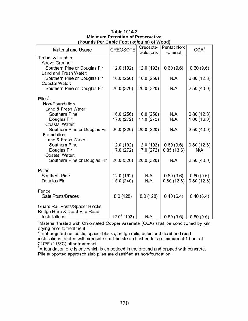
830
Table 1014-2 Minimum Retention of Preservative
(Pounds Per Cubic Foot (kg/cu m) of Wood)
Material and Usage CREOSOTE Creosote-Solutions
Pentachloro-phenol CCA1
Timber & Lumber Above Ground: Southern Pine or Douglas Fir Land and Fresh Water: Southern Pine or Douglas Fir Coastal Water: Southern Pine or Douglas Fir Piles3 Non-Foundation Land & Fresh Water: Southern Pine Douglas Fir Coastal Water: Southern Pine or Douglas Fir Foundation Land & Fresh Water: Southern Pine Douglas Fir Coastal Water: Southern Pine or Douglas Fir Poles Southern Pine Douglas Fir Fence Gate Posts/Braces Guard Rail Posts/Spacer Blocks, Bridge Rails & Dead End Road Installations
12.0 (192)
16.0 (256)
20.0 (320)
16.0 (256) 17.0 (272)
20.0 (320)
12.0 (192) 17.0 (272)
20.0 (320)
12.0 (192) 15.0 (240)
8.0 (128)
12.02 (192)
12.0 (192)
16.0 (256)
20.0 (320)
16.0 (256)17.0 (272)
20.0 (320)
12.0 (192)17.0 (272)
20.0 (320)
N/A N/A
8.0 (128)
N/A
0.60 (9.6)
N/A
N/A
N/A N/A
N/A
0.60 (9.6) 0.85 (13.6)
N/A
0.60 (9.6) 0.80 (12.8)
0.40 (6.4)
0.60 (9.6)
0.60 (9.6)
0.80 (12.8)
2.50 (40.0)
0.80 (12.8)1.00 (16.0)
2.50 (40.0)
0.80 (12.8)N/A
2.50 (40.0)
0.60 (9.6) 0.80 (12.8)
0.40 (6.4)
0.60 (9.6) 1Material treated with Chromated Copper Arsenate (CCA) shall be conditioned by kiln drying prior to treatment. 2Timber guard rail posts, spacer blocks, bridge rails, poles and dead end road installations treated with creosote shall be steam flushed for a minimum of 1 hour at 240ºF (116ºC) after treatment. 3A foundation pile is one which is embedded in the ground and capped with concrete. Pile supported approach slab piles are classified as non-foundation.
831
Section 1015 Signs and Pavement Markings
1015.01 GENERAL REQUIREMENTS. The materials shall comply with these specifications, the plans and the MUTCD. When directed, the contractor shall furnish and prepare samples for testing in accordance with Department instructions. 1015.02 METALS. (a) Ferrous Metals: (1) Structural Steel: Structural steel for posts, stringers, framing and miscellaneous steel shall comply with AASHTO M 270, Grade 36 (M 270M, Grade 250). Steel shall be galvanized in accordance with Subsection 811.12. (2) Steel Pipe: Steel pipe or tubing for structures shall be Schedule 40 (STD) complying with ASTM A 53, Type E or Type S Grade B, or hot formed tubing complying with ASTM A 36 (ASTM A 36M) and ASTM A 501. (3) Steel Posts for Small Signs, Markers and Delineators: Posts shall be steel of the flanged channel type shown on the plans, galvanized after fabrication in accordance with Subsection 811.12. Before fabrication, posts shall be within 3.5 percent of the specified weight (mass). Posts shall be fabricated from steel complying with either ASTM A 499, Grade 60 with chemical properties conforming to ASTM A 1 for 91-lb/yd (45 kg/m) or heavier rail steel, or ASTM A 576, Grade 1080 with 0.10 percent -0.20 percent silicon. Holes 3/8 inch (10 mm) in diameter shall be drilled or punched through the middle of each post on one inch (25-mm) centers for at least 36 inches (900 mm) from the top of each post. (b) Aluminum Alloy: Structural members shall be aluminum complying with ASTM B 221 (ASTM B 221M) or ASTM B 429, Alloy 6061-T6. Miscellaneous aluminum shall comply with ASTM B 209 (ASTM B 209M), Alloy 6061-T6. (c) Fittings: (1) Structural Bolts, Nuts and Washers: High strength bolts shall be ASTM A 325 (ASTM A 325M), and other bolts shall be ASTM A 307, Grade A or Grade B. Bolts shall have hexagonal heads and be supplied with two flat and one lock washer and hexagonal-head nut. Bevel washers, where required, shall be wrought steel. Bolts, nuts and washers

1015.02
832
shall be galvanized in accordance with ASTM A 153 or by an approved mechanical galvanizing process complying with ASTM B 695 that provides the same coating thickness. Anchor bolts shall be AASHTO M 270, Grade 36 (M 270M, Grade 250) steel except the maximum tensile strength shall be 88,000 psi (605 MPa) and galvanized in accordance with Subsection 811.12 unless otherwise specified. Stainless steel bolts shall comply with ASTM A 320 (ASTM A 320M), Grade B 8, annealed or approved equal. (2) Fasteners: Fasteners used in fabricating sign faces, including splice plates for joining two panels, sills and border angles, and attaching route marker shields shall be 1/4 inch (6 mm) aluminum blind rivets that provide positive mandrel retention. These rivets shall have a minimum tensile strength of 875 pounds (397 kg) and a minimum sheer strength of 850 pounds (386 kg). Fasteners used in attaching demountable legend to sign faces (except for shields) shall be 1/8 inch (3 mm) diameter blind rivets manufactured from aluminum alloy complying with ASTM B 316 (ASTM B 316M), Alloy 1100-H14. Fasteners for delineator, object marker and milepost assemblies shall be vandal resistant and will be subject to approval prior to use. 1015.03 FLEXIBLE POSTS. Flexible posts for small signs, markers and delineators shall be approved products listed in QPL 39. 1015.04 SIGN PANELS. (a) Permanent Sign Panels: Flat panels shall be aluminum sheets or plates complying with ASTM B 209, Alloy 6061-T6 or Alloy 5052-H38. Extruded aluminum panels shall comply with ASTM B 221 (ASTM B 221M), Alloy 6063-T6. (b) Temporary Sign Panels: Substrate for barricade panels shall be either wood or rigid thermoplastic. Substrate for portable signs shall be aluminum, wood or plastic. Substrate for post mounted signs shall be aluminum, wood, rigid thermoplastic or aluminum clad low density polyethylene plastic. (1) Aluminum: Aluminum sheeting shall be 0.080 inch (2 mm) thickness complying with ASTM B 209 (ASTM B 209M), Alloy 6061-T6 or Alloy 5052-H38.

1015.05
833
(2) Wood: Plywood sheeting of exterior type Grades either High Density Overlay or Medium Density Overlay, are acceptable for use provided the following requirements are met. Panels shall be a minimum of 5/8 inch (15 mm) thick and shall comply with the latest American Plywood Association specifications and be identified with the APA edge mark or back stamp to verify inspection and testing. Prior to application of reflective sheeting, the surface shall be abraded with steel wool or fine sandpaper, and wiped thoroughly clean. The surface shall be allowed to dry a minimum of 8 hours prior to application of sheeting. Cut edges of plywood panels shall be sealed with an approved aluminum pigmented polyurethane sealer. (3) Plastic: Plastic substrate for barricade panels and signs shall be as follows. a. Fiber Reinforced Vinyl (PVC): The substrate shall have a nominal composite thickness of 0.04 inches (1 mm) and be bonded to an approved retroreflective material by the manufacturer. b. Rigid Thermoplastic: Rigid thermoplastic substrate shall consist of either High Density Polyethylene (HDPE) or High Density Polycarbonate (HDPC). The rigid thermoplastic for barricade panels shall be hollow core HDPE or HDPC with a minimum thickness of 0.625 inch (16 mm). The thermoplastic for sign panels shall be either 0.40 inch (10 mm) thick thin wall, fluted substrate or 0.625 inch (16 mm) thick blow molded substrate. Substrates shall be sufficiently rigid to maintain a flat face and shall be capable of attachment to the sign mounting in such a manner as not to crush or otherwise deform the substrate. Reflectorized sheeting applied to rigid thermoplastic shall have its manufacturer's approval for use on the substrate. c. Aluminum Clad Low Density Polyethylene (AL/LDPE) Plastic: The aluminum clad low density polyethylene plastic substrate shall be 0.080 inch (2 mm) thick. The substrates shall be sufficiently rigid to maintain a flat face and shall be capable of attachment to the sign mounting in such a manner as not to crush or otherwise deform the substrate. Reflectorized sheeting applied to aluminum clad low density polyethylene shall have its manufacturer's approval for use on this substrate. 1015.05 REFLECTIVE SHEETING. (a) Permanent and Temporary Standard Sheeting: Reflective sheeting shall be one of the following standard types as specified on the plans and complying with ASTM D 4956 except as modified herein. The sheeting shall be an approved product listed in QPL 13.
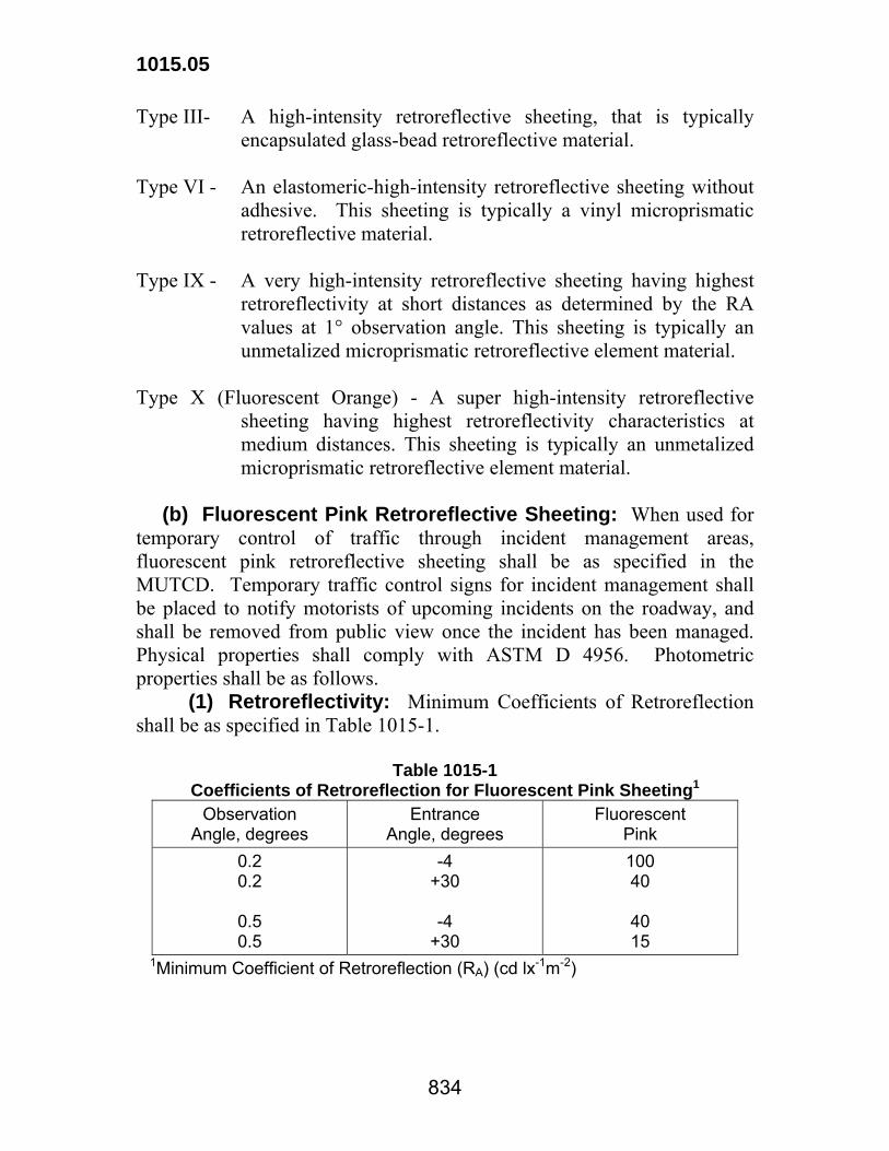
1015.05
834
Type III- A high-intensity retroreflective sheeting, that is typically encapsulated glass-bead retroreflective material.
Type VI - An elastomeric-high-intensity retroreflective sheeting without
adhesive. This sheeting is typically a vinyl microprismatic retroreflective material.
Type IX - A very high-intensity retroreflective sheeting having highest
retroreflectivity at short distances as determined by the RA values at 1° observation angle. This sheeting is typically an unmetalized microprismatic retroreflective element material.
Type X (Fluorescent Orange) - A super high-intensity retroreflective
sheeting having highest retroreflectivity characteristics at medium distances. This sheeting is typically an unmetalized microprismatic retroreflective element material.
(b) Fluorescent Pink Retroreflective Sheeting: When used for temporary control of traffic through incident management areas, fluorescent pink retroreflective sheeting shall be as specified in the MUTCD. Temporary traffic control signs for incident management shall be placed to notify motorists of upcoming incidents on the roadway, and shall be removed from public view once the incident has been managed. Physical properties shall comply with ASTM D 4956. Photometric properties shall be as follows. (1) Retroreflectivity: Minimum Coefficients of Retroreflection shall be as specified in Table 1015-1.
Table 1015-1 Coefficients of Retroreflection for Fluorescent Pink Sheeting1
Observation Angle, degrees
Entrance Angle, degrees
Fluorescent Pink
0.2 0.2
0.5 0.5
-4 +30
-4
+30
100 40
40 15
1Minimum Coefficient of Retroreflection (RA) (cd lx-1m-2)

1015.05
835
(2) Color and Daytime Luminance: Color Chromaticity Coordinates and Daytime Luminance Factors shall be as specified in Table 1015-2.
Table 1015-2 Fluorescent Pink Color Specifications Limits (Daytime)
Chromaticity Coordinates (corner points) 1 Luminance Factor, min.
1 2 3 4 Y% x y x y x y x y
0.450 0.270 0.590 0.350 0.644 0.290 0.536 0.230 25 1The four pairs of chromaticity coordinates measured with CIE 2° Standard Observer and 45/0 (0/45) geometry and CIE D65 Standard Illuminant. (c) Adhesive Classes: The adhesive required for retroreflective sheeting shall be Class 1 (pressure sensitive) or Class 2 (heat activated) as specified in ASTM D 4956. (d) Accelerated Weathering: Reflective sheeting, when processed, applied and cleaned in accordance with the manufacturer's recommendations shall perform in accordance with the accelerated weathering standards in Table 1015-3.

1015.05
836
Table 1015-3 Accelerated Weathering Standards1
Retroreflectivity2 Colorfastness3 Type
Orange All colors, except orange Orange All colors,
except orangeIII 1 year 804 3 years 804 1 year 3 years III
(for drums) 1 year 804 1 year 804 1 year 1 year
VI 1/2 year 505 1/2 year 505 1/2 year 1/2 year
IX Not used 3 years 806 Not used 3 years X
(Fluorescent Orange)
1 year 807 Not used 1 year Not used
1At an angle of 45° from the horizontal and facing south in accordance with ASTM G 7 at an approved test facility in Louisiana or South Florida. 2Percent retained retroreflectivity of referenced table after the outdoor test exposure time specified. 3Colors shall conform to the color specification limits of ASTM D 4956 after the outdoor test exposure time specified. 4ASTM D 4956, Table 8. 5ASTM D 4956, Table 13. 6ASTM D 4956, Table 3. 7ASTM D 4956, Table 4.
(e) Performance: Reflective sheeting for signs, when processed, applied and cleaned in accordance with the manufacturer's recommendations shall perform outdoors in accordance with the performance standards in Table 1015-4.

1015.05
837
Table 1015-4 Reflective Sheeting Performance Standards
Retroreflectivity1 -- Durability2 Type Orange All colors, except
orange Colorfastness3
III 3 years 804 10 years 804 3 years IX Not used 7 years 805 3 years
X (Fluorescent. Orange) 3 years 806 Not used 3 years
1Percent retained retroreflectivity of referenced table after installation and the field exposure time specified. 2All sheeting shall maintain its structural integrity, adhesion and functionality after installation and the field exposure time specified. 3All colors shall conform to the color specification limits of ASTM D4956 after installation and the field exposure time specified. 4ASTM D4956, Table 8. 5ASTM D 4956, Table 3. 6ASTM D 4956, Table 4. (f) Temporary Signs, Barricades, Channelizing Devices, Drums and Cones: Reflective sheeting for temporary signs, barricades and channelizing devices, shall meet the requirements of ASTM D 4956, Type III except that the initial sequence of temporary advanced warning construction signs used on the mainline of freeways and expressways shall meet the requirements of ASTM D 4956, Type X (Fluorescent Orange). Reflective sheeting for vertical panels shall meet the requirements of ASTM D 4956, Type III. Reflective sheeting for drums shall be a minimum of 6 inches (150 mm) wide and shall meet the requirements of ASTM D 4956, Type III, and the Supplementary Requirement S2 for Reboundable Sheeting as specified in ASTM D 4956. Reflective sheeting for traffic cone collars shall meet the requirements of ASTM D 4956, Type VI. (g) Sheeting Guaranty. The contractor shall provide the Department with a guaranty from the sheeting manufacturer stating that if the retroreflective sheeting fails to comply with the performance requirements of this subsection, the sheeting manufacturer shall do the following:

1015.05
838
Table 1015-5 Manufacturer's Guaranty-Reflective Sheeting
Manufacturer shall restore the sign face in its field location to its original effectiveness at no cost to the Department if failure occurs during the time period1 as specified below
Manufacturer shall replace the sheeting required to restore the sign face to its original effectiveness at no cost to the Department if failure occurs during the time period1 as specified below
Type
Orange All colors, except orange
All colors, except orange
III <3 years <7 years 7-10 years
IX Not used <5 years 5-10 years
X (Fluorescent Orange)
<3 years Not used Not used
1From the date of sign installation. Replacement sheeting for sign faces, material, and labor shall carry the unexpired guaranty of the sheeting for which it replaces. The sign fabricator shall be responsible for dating all signs with the month and year of fabrication at the time of sign fabrication. This date shall constitute the start of the guaranty obligation period. 1015.06 NONREFLECTIVE SHEETING. (a) General Requirements: Nonreflective sheeting film shall consist of an extensible, pigmented, weather-resistant plastic film. Face side of film shall be supported and protected by a paper liner which is readily removable after application without the necessity of soaking in water or other solvents. Colors shall be matched visually and be within the limits shown in Table 17 of ASTM D 4956. (b) Adhesive Requirements: Sheeting shall have a precoated pressure-sensitive adhesive backing or a tack-free heat-activated adhesive backing, either of which may be applied without additional coats on either sheeting or application surface. Adhesive shall comply with ASTM D 4956, Class 1 (pressure sensitive) or Class 2 (heat activated). (c) Physical Characteristics: The film shall be readily cut by normal fabricating methods without cracking, checking or flaking. Applied film shall be free from ragged edges, cracks and blisters. The material
1015.08
839
shall have demonstrated its ability to withstand normal weathering without checking, cracking or excessive color loss. 1015.07 SIGN ENAMELS, PAINTS, SILK SCREEN PASTE AND OVERLAY FILM. (a) Sign Enamels and Paints: These shall be applied in accordance with the sheeting manufacturer's recommendations. Final appearance as well as materials used shall be subject to approval. (b) Silk Screen Paste: Constituents used in manufacture of silk screen paste shall meet approval of the engineer. Silk screen paste shall be mixed at the factory, well ground to a uniform consistency and smooth texture, and shall be free from water and other foreign matter. It shall dry within 18 hours to a film that does not run, streak, or sag. Paste which has livered, hardened or thickened in the container, or in which pigment has settled out so that it cannot be readily broken up with a paddle to a uniform usable consistency, will be rejected. Paste and thinner shall be used in accordance with the sheeting manufacturer's recommendations. Paste shall have proper pigmentation and consistency for use in silk screen equipment. The material shall produce the desired color and the same retroreflectivity values as required for reflective sheeting of the same type and color when applied on reflective sheeting background. Paste shall meet the quality and test requirements for appearance, coarse particles, and moisture and water resistance as specified for sign paints. (c) Overlay Film: Transparent electronic cuttable overlay film shall produce the desired color and the same reflectivity values as required for reflective sheeting of the same type and color when applied on reflective sheeting background. The film shall be an approved product listed in QPL 13. 1015.08 TEMPORARY PAVEMENT MARKINGS. (a) Temporary Tape: Temporary tape shall comply with ASTM D 4592, Type I (removable) or Type II (non-removable) and shall be an approved product listed in QPL-60. (b) Painted Stripe: Paint shall be an approved traffic paint complying with Subsection 1015.12. Glass beads for drop-on application shall comply with Subsection 1015.13. (c) Temporary Raised Pavement Markings for Asphaltic Surface Treatment: Temporary raised pavement markers for asphaltic surface treatment shall be flexible reflective tabs having a nominal width of 4 inches (10 cm). The markers shall be yellow with amber reflective area

1015.08
840
on both sides. The body of the marker shall consist of a base and vertical wall made of polyurethane or other approved material and shall be capable of maintaining a reasonable vertical position after installation. The initial minimum Coefficient of Luminous Intensity at an entrance angle of -4 degrees and an observation angle of 0.2 degrees shall be 230 mcd/lx when measured in accordance with ASTM E 810. The reflective material shall be protected with an easily removable cover of heat resistant material capable of withstanding and protecting the reflective material from the application of asphalt at temperatures exceeding 325°F (160°C). 1015.09 RAISED PAVEMENT MARKERS. Markers shall be either nonreflectorized or reflectorized, as specified. Markers shall be approved products listed in QPL 9. Infrared curves of materials used in markers shall match approved curves on file at the Department's Materials and Testing Section. (a) Nonreflectorized Markers: (1) Description: Nonreflectorized markers shall consist of an acrylonitrile-butadiene-styrene polymer or other approved material, and shall be 4-by-6-inches (100-by-150-mm). (2) Physical Requirements: Markers shall comply with the compressive strength requirements of ASTM D 4280. The color shall be in accordance with the plans and the MUTCD. (b) Reflectorized Markers: Reflectorized markers shall comply with ASTM D 4280, Designation H and Designation F. The type and color shall be in accordance with the plans and the MUTCD. The markers shall be either standard having approximate base dimensions of 4-by-4-inches (100-by-100-mm) and a maximum height of 0.80 inches (20 mm) or low profile having approximate base dimensions of 4-by-2-inches (100-by-50-mm) and a maximum height of 0.60 inches (15 mm). (c) Adhesive: (1) Epoxy Adhesive: Epoxy adhesive shall be Type V epoxy resin system complying with Subsection 1017.02. (2) Bituminous Adhesive: The adhesive shall conform to ASTM D 4280 and shall be an approved product listed in QPL 59. 1015.10 THERMOPLASTIC PAVEMENT MARKINGS. (a) Description: This specification covers hot-sprayed or hot-extruded reflective thermoplastic compound for pavement markings on asphaltic or portland cement concrete pavement. Thermoplastic marking

1015.10
841
material applied to asphaltic surfaces shall consist of an alkyd based formulation. Thermoplastic marking material applied to portland cement concrete surfaces shall consist of either an alkyd based or hydrocarbon based formulation. Material shall be so manufactured as to be applied by spray (40 mil (1.0 mm)) or extrusion to pavement in molten form, with internal and surface application of glass spheres, and upon cooling to normal pavement temperature, shall produce an adherent, reflectorized pavement marking of specified thickness and width, capable of resisting deformation. Material shall not scorch, break down, or deteriorate when held at the plastic temperature specified in Subsection 732.03(f)(1) for 4 hours or when reheated four times to the plastic temperature. Temperature-vs-viscosity characteristics of plastic material shall remain constant when reheated four times, and shall be the same from batch to batch. There shall be no obvious change in color of material as the result of reheating four times or from batch to batch. (b) Suitability for Application: Thermoplastic material shall be a product especially compounded for pavement markings. Markings shall maintain their original dimension and placement and shall not smear or spread under normal traffic at temperatures below 140°F (60°C). Markings shall have a uniform cross section. Pigment shall be evenly dispersed throughout the material thickness. The exposed surface shall be free from tack and shall not be slippery when wet. Material shall not lift from pavement in freezing weather. Cold ductility of material shall be such as to permit normal movement with the pavement surfaced without chipping or cracking. (c) Standard (Flat) Thermoplastic Pavement Markings: Materials shall be approved products listed in QPL 63 and shall comply with AASHTO M 249 as modified herein: (1) Color: a. Laboratory Performance: The yellow thermoplastic shall comply with the requirements of Table 1015-6 when tested in accordance with ASTM E 1349.
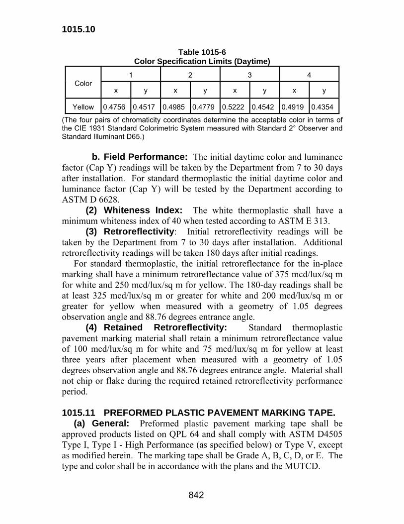
1015.10
842
Table 1015-6 Color Specification Limits (Daytime)
1
2
3
4
Color
x
y
x
y
x
y
x
y
Yellow
0.4756
0.4517
0.4985
0.4779
0.5222
0.4542
0.4919
0.4354
(The four pairs of chromaticity coordinates determine the acceptable color in terms of the CIE 1931 Standard Colorimetric System measured with Standard 2° Observer and Standard Illuminant D65.) b. Field Performance: The initial daytime color and luminance factor (Cap Y) readings will be taken by the Department from 7 to 30 days after installation. For standard thermoplastic the initial daytime color and luminance factor (Cap Y) will be tested by the Department according to ASTM D 6628. (2) Whiteness Index: The white thermoplastic shall have a minimum whiteness index of 40 when tested according to ASTM E 313. (3) Retroreflectivity: Initial retroreflectivity readings will be taken by the Department from 7 to 30 days after installation. Additional retroreflectivity readings will be taken 180 days after initial readings. For standard thermoplastic, the initial retroreflectance for the in-place marking shall have a minimum retroreflectance value of 375 mcd/lux/sq m for white and 250 mcd/lux/sq m for yellow. The 180-day readings shall be at least 325 mcd/lux/sq m or greater for white and 200 mcd/lux/sq m or greater for yellow when measured with a geometry of 1.05 degrees observation angle and 88.76 degrees entrance angle. (4) Retained Retroreflectivity: Standard thermoplastic pavement marking material shall retain a minimum retroreflectance value of 100 mcd/lux/sq m for white and 75 mcd/lux/sq m for yellow at least three years after placement when measured with a geometry of 1.05 degrees observation angle and 88.76 degrees entrance angle. Material shall not chip or flake during the required retained retroreflectivity performance period. 1015.11 PREFORMED PLASTIC PAVEMENT MARKING TAPE. (a) General: Preformed plastic pavement marking tape shall be approved products listed on QPL 64 and shall comply with ASTM D4505 Type I, Type I - High Performance (as specified below) or Type V, except as modified herein. The marking tape shall be Grade A, B, C, D, or E. The type and color shall be in accordance with the plans and the MUTCD.

1015.11
843
(b) Thickness: All preformed plastic pavement marking tape shall have a minimum overall thickness of 0.060 inches (1.5 mm) when tested without the adhesive. (c) Friction Resistance: The surface of the Type I preformed plastic pavement marking tape shall provide a minimum frictional resistance value of 35 British Polish Number (BPN) when tested according to ASTM E303. The surface of the Type I - High Performance and Type V preformed plastic pavement marking tape shall provide a minimum frictional resistance value of 45 BPN when tested according to ASTM E303 except values for the Type V are calculated by averaging values taken at downweb and at a 45 degrees angle from downweb. (d) Retroreflective Requirements: The preformed plastic pavement marking tape shall have the minimum initial specific luminance values shown in Table 1015-7 when measured in accordance with ASTM D 4061.
Table 1015-7 Specific Luminance of Preformed Plastic Tape
Specific Luminance (mcd/sq m/lx)
Type
Observation
Angle, degrees
Entrance
Angle, degrees White Yellow I 1.05 88.76 250 175 I - High Performance 1.05 88.76 375 250 V 1.05 88.76 500 300
(e) Durability Requirements: The Type I - High Performance preformed plastic pavement marking tape shall show no appreciable fading, lifting or shrinkage for a least 12 months after placement when placed in accordance with the manufacturer's recommended procedures on pavement surfaces having a daily traffic count not to exceed 15,000 ADT per lane. The Type V preformed plastic pavement marking tape shall show no appreciable fading, lifting or shrinkage for a least 4 years after placement for longitudinal lines and at least 2 years after placement for symbols and legends. The Type V preformed plastic pavement marking tape shall also retain the following reflectance values for the time period detailed in Table 1015-8.

1015.11
844
Table 1015-8 Retained Specific Luminance for Type V
Preformed Plastic Pavement Marking Tape Specific
Luminance (mcd/sq m/lx)
Time
Observation
Angle, degrees
Entrance
Angle, degrees White Yellow
1 year 1.05 88.76 400 240 4 years (2 years for symbols and legend)
1.05 88.76 100 100
(f) Plastic Pavement Marking Tape Guaranty (Type I - High Performance and Type V): If the plastic pavement marking tape fails to comply with the performance and durability requirements of this subsection within 12 months for Type I - High Performance and 4 years for Type V, the manufacturer shall replace the plastic pavement marking material at no cost to the Department. 1015.12 TRAFFIC PAINT. The contractor shall have the option of furnishing either alkyd traffic paint or water-borne traffic paint; however, the same type paint shall be used throughout the project. Each paint container shall bear a label with the name and address of manufacturer, trade name or trademark, type of paint, number of gallons, batch number and date of manufacture. Paints shall be approved products listed in QPL 36, shall show no excessive settling, caking or increase in viscosity during 6 months of storage, and shall be readily stirred to a suitable consistency for standard spray gun application. An infrared curve shall be generated in accordance with DOTD TR 610 and compared with the standard curve made during the initial qualification process. (a) Alkyd Traffic Paint: This material shall be a rapid-setting compound suitable for use with hot application equipment. The material shall meet the requirements of Table 1015-9.

1015.12
845
Table 1015-9 Alkyd Traffic Paint Physical Properties
Requirements Property
Test Method Min. Max.
Weight, kg/L ASTM D 1475 1.5 --- Viscosity @ 25°C, Krebs Units ASTM D 562 85 115 Dry to No Pick Up, s ASTM D 711 --- 180
ASTM E 97 80 ---
Directional Reflectance, % White Yellow 50 --- Bleeding Fed. Spec. TT-P-115 Pass Total Solids, % by mass ASTM D 1644, Method A 70 --- Film Shrinkage 1 Pass Hiding Power 2 Pass Pigment, % ASTM D 2371 50 55 Nonvolatiles in Vehicle, % by mass ASTM D 215 35 --- Flexibility Fed. Spec. TT-P-1952 Pigment Composition 3
Pass Pass
1Film Shrinkage: With a film applicator, cast a wet film with a thickness of 30 mils (750 μm) over a smooth glass plate. Allow sample to cure at room condition for 4 to 5 hours. Using a micrometer, measure the plate thickness before the film is cast using five measurements to obtain an average. The cured film shall have a minimum thickness of 12 mils (300 μm). 2Hiding Power: The paint shall have a wet hiding power of at least 350 square feet per gallon (8.6 m2/L). The compound shall have sufficient hiding power to cover any pavement when applied at a wet film thickness of 15 mils (375 μm). 3Pigment Composition: White paint shall contain at least 1.5 pounds (180 g) of titanium dioxide (Ti02) pigment per gallon as determined using DOTD TR 523 with at least 92 percent Ti02 content. The Ti02 shall comply with ASTM D 476. Yellow paint shall contain at least 1.3 pounds (160 g) of medium chrome yellow pigment per gallon (L) as determined using DOTD TR 523. Medium chrome yellow pigment shall comply with ASTM D 211, Type III. (b) Water Borne Traffic Paint: This material shall be a rapid setting waterborne compound suitable for use with hot application equipment. The material shall meet the requirements of Table 1015-10.

1015.12
846
Table 1015-10 Water Borne Traffic Paint Physical Properties
Requirements Property Test Method Min. Max. pH ASTM E 70 9.9 --- Viscosity, at 25°C Krebs Unit ASTM D 562 78 95 Drying Time, minutes1 ASTM D 711 --- 10 Total Solids, % by mass ASTM D 2369 73 79 Percent Pigment2 ASTM D 3723 55 62 Nonvolatiles in Vehicle, % by weight ASTM D 215 43 --- Weight per Gallon, lb/gal ASTM D 1475 --- --- White 13.7 --- Yellow 13.1 --- Daylight Reflectance, % ASTM E 1349 White 80 --- Yellow 50 --- Fineness of Grind ASTM D 1210 3 --- Color 3 Pass Shelf Life, months 12 --- Pigment Composition 4 Pass Infrared Spectroscopy (IR) DOTD TR 610 Pass
1Drying time to no track - Paint applied at 15 mils (375 μm) wet on the road surface with paint heated to 120-150°F (50-65°C) shall not show tracking when a standard size automobile crosses in a passing maneuver at 3 minutes. 2 No theoretical empirical factor shall be applied in determining the percent of the paint. Percent pigment shall not be calculated by adding back the burned-off organic constituents of the pigment. 3Color (without glass beads) - Yellow paint shall comply with the requirements of Table 1015-11 when tested in accordance with ASTM E 1349. White shall be a clean, bright, untinted binder. 4The white paint shall contain a minimum of 1.0 pound per gallon (120 g/L) of titanium dioxide (Ti02) as determined using DOTD TR 523. The titanium dioxide shall comply with ASTM D 476.
Table 1015-11 Water Borne Traffic Paint Color Specification Limits (Daytime)
1
2
3
4
Color
x
y
x
y
x
y
x
y
Yellow
0.493
0.473
0.518
0.464
0.486
0.428
0.469
0.452
(The four pairs of chromaticity coordinates determine the acceptable color in terms of the CIE 1931 Standard Colorimetric System measured with Standard 2° Observer and Standard Illuminant D65.) (c) Initial Retroreflectivity: For traffic paint, initial retroreflectance shall have a minimum retroreflectance of 250 mcd/lux/sq m for white and 175 mcd/lux/sq m for yellow when measured with a geometry of 1.05

1015.13
847
degrees observation angle and 88.76 degrees entrance angle (30 m geometry). The initial retroreflectivity readings shall be taken between 7 and 30 days after installation. (d) Initial Daytime Color and Luminance Factor: For traffic paint, initial daytime color and luminance factor (Cap Y) will be tested according to and in compliance with the requirements of ASTM D6628. The readings will be taken by the Department from 7 to 30 days after installation. (e) Durability: Traffic paint shall retain the minimum reflectance value of 150 mcd/lux/sq m for white and 100 mcd/lux/sq m for yellow at least 6 months after placement when measured with a geometry of 1.05 degrees observation angle and 88.76 degrees entrance angle (30 m geometry). Material shall not chip or flake during the 6 months after placement. Failure to meet this requirement shall require the contractor to replace the portion of the material shown to be below these minimums. 1015.13 GLASS BEADS FOR PAVEMENT MARKINGS. Glass beads for use with painted traffic striping and flat thermoplastic striping shall be transparent, clean, colorless glass, smooth and spherically shaped, free from milkiness, pits, or excessive air bubbles and conform to the specific requirements for the class designated. The beads shall be non-flotation, embedment coated and conform to the following specific requirements. (a) Moisture Resistance - Flow Characteristics: The beads shall not absorb moisture in storage. They shall remain free of clusters and lumps and shall flow freely from the dispensing equipment. (b) Gradation: The testing for gradation of the beads shall be in accordance with ASTM D 1214 and shall meet the gradation requirements specified below. (1) Painted Traffic Striping: Glass beads for painted traffic striping shall meet the gradation requirements of Table 1015-12.

1015.13
848
Table 1015-12 Gradation of Large Embedment Coated Glass Beads for
Painted Traffic Striping U.S. SIEVE (METRIC SIEVE) PERCENT RETAINED
No. 12 (1.7 mm) 0 No. 14 (1.4 mm) 0-5
No. 16 (1.18 mm) 5-20 No. 18 (1.00 mm) 40-80 No. 20 (850 µm) 10-40 No. 25 (710 µm) 0-5
PAN 0-2 (2) Flat Profile Thermoplastic Striping: Drop-on beads for flat profile thermoplastic striping shall meet the gradation requirements of Table 1015-13 as determined by the thickness of the striping.
Table 1015-13 Gradation of Embedment Coated Glass Beads for
Flat Profile Thermoplastic Striping
THICKNESS NUMBER OF BEAD DROPS APPLICATION #1 APPLICATION #2
40 mils Single Drop See Table 1015-12 N/A
90 mils or greater Double Drop See Table 1015-14 AASHTO M 247
Type I
Table 1015-14
Gradation of Large Embedment Coated Glass Beads for First Drop on Flat Thermoplastic Striping
U.S. SIEVE (METRIC SIEVE) PERCENT RETAINED
No. 10 (2.0 mm) 0 No. 12 (1.7 mm) 0-5 No. 14 (1.4 mm) 5-20
No. 16 (1.18 mm) 40-80 No. 18 (1.00 mm) 10-40 No. 20 (850 µm) 0-5
PAN 0-2

1015.13
849
(c) Roundness: The beads shall have a minimum of 80 percent rounds per screen for the two (2) highest sieve quantities. The remaining sieve fractions shall have no less than 75 percent rounds as determined by microscopic examination. (d) Angular Particles: The beads shall have no more than three (3) percent angular particles per screen. (e) Refractive Index: The beads shall have a refractive index of 1.50 to 1.52 when tested by the liquid immersion method. (f) Embedment Coating: The large beads for thermoplastic striping shall be coated with an adhesion assuring coating. The smaller AASHTO M247 Type I beads shall be coated to provide free flowing characteristics when tested in accordance with AASHTO M247 Section 4.4.1. and assure adhesion. Glass beads shall be properly coated and conform to the requirements when tested as described in DOTD TR 530 Determination of Embedment Coating on Large Embedment Coated Glass Beads for Pavement Markings. (g) Packaging and Marking: The beads shall be packaged in moisture proofed containers. Each container shall be stamped with the following information: Name and address of manufacturer, shipping point, trademark or name, the wording "Large Embedment Coated Glass Beads", class, weight, lot number and the month and year of manufacture. The container for the AASHTO M 247 Type I beads shall be similarly stamped except that the wording shall be "Glass Beads".

850
Section 1016 Precast Reinforced Concrete Drainage Units
1016.01 GENERAL. This specification covers the manufacture of precast reinforced concrete box culverts, manhole sections, catch basins, junction boxes, and safety ends. Precast reinforced concrete drainage units shall be as listed on QPL 77. (a) Portland Cement and Portland-Pozzolan Cement: Portland cement shall comply with Subsection 1001.01. Portland-pozzolan cement shall comply with Subsection 1001.02. (b) Admixtures: Any admixture for portland cement concrete listed in QPL 58 is allowed for use in the manufacture of precast units except for chloride-type accelerators and high range water reducers. (c) Strength: Compressive strength specimens for precast units shall be made and cured in accordance with DOTD TR 226 or DOTD TR 227, and tested in accordance with DOTD TR 230. Compressive strength shall comply with ASTM C 76 (C 76M). (d) Pipe Connections: For grout connections, each opening shall be 4±1/2 inches (100±13 mm) larger than the outside diameter of the pipe for which it is provided. Units shall be cast with the specified number and size of pipe openings to incorporate the unit into the drainage system. Other methods for connecting pipe to precast units using resilient connectors shall conform to ASTM C 923. (e) Marking: The name or trademark of the manufacturer, the date of casting, the structure number or the station number as shown on the plans, and the lot number shall be indented into the concrete or painted thereon with waterproof paint on each unit on the inside and outside of the unit in such a manner as to be legible at time of delivery. 1016.02 PRECAST REINFORCED CONCRETE BOX CULVERTS. Precast reinforced concrete box culverts shall be approved products listed on QPL 77. The compressive strength of box culverts shall comply with ASTM C 76 (C 76M). Precast reinforced concrete box culverts shall comply with ASTM C 1433 amended as follows: (a) Table 1 shall be used. (b) No modified designs will be allowed. (c) Joints shall be approved by the Materials and Testing Section, and shall comply with the following:

1016.03
851
(1) Joint gasket materials shall comply with Subsection 1006.06. (2) Type 1 Joints (T1): These joints shall provide a soil tight joint. (3) Type 2 Joints (T2): These joints shall pass the 5 psi (35 kPa) hydrostatic pressure test. (4) Type 3 Joints (T3): These joints shall pass the 10 psi (70 kPa) hydrostatic pressure test. (d) Inside horizontal and vertical dimensions shall not vary by more than ±1 percent with a maximum of ±1/2 inch (±13 mm) from design dimensions. (e) Sides of each box section shall not vary from being perpendicular to the top and bottom by more than 1/2-inch (±13 mm) when measured diagonally between opposite interior corners of each end. (f) Culvert units shall be cured by one of the methods listed in ASTM C 1433. The selected method shall be approved by the Construction Section. 1016.03 PRECAST REINFORCED CONCRETE MANHOLES, CATCH BASINS, JUNCTION BOXES, AND SAFETY ENDS. Precast reinforced concrete manholes, catch basins, junction boxes, and safety ends shall comply with the dimensions shown on the plans, and shall meet the following requirements: (a) Materials: (1) Precast reinforced concrete manholes, catch basins and junction boxes shall comply with the following Sections and Subsections: Portland Cement Concrete, Class M 901 Reinforcing Steel 1009 Frames, Grates and Covers 1018.04 Portland cement concrete shall attain a minimum compressive strength of 4000 psi (27.6 MPa) before shipping of the units. (2) Precast safety ends shall comply with Subsection 702.04(c). (b) Casting Concrete: When multiple castings are to be made using the same forms, the engineer may require the use of metal forms. Concrete in each sectional unit shall be placed without interruption and shall be consolidated by the use of an approved vibrator, supplemented by hand-tamping as necessary, to force the concrete into the corners of forms and prevent formation of stone pockets or cleavage planes. (c) Reinforcement: Reinforcement shall be as shown on the plans, and shall not vary more than 1/4 inch (6 mm) from the positions shown, except at pipe connections. At pipe connections no variance from the

1016.03
852
positions shown is allowed. Cover on reinforcement shall not be less than that shown on the plans. (d) Curing: Units shall be cured in accordance with Subsection 805.10 or Subsection 805.14(e). (e) Form Removal: Forms shall remain in place for 1 curing day in accordance with Subsection 805.11, Method 2. (f) Joints and Gasket Material: Joints and gasket material shall comply with Subsection 1006.06(b). (g) Workmanship: Units shall be true to shape, and surfaces shall be smooth, dense and uniform in appearance. Units will be rejected for defeats in workmanship for any of the following: (1) Fractures or cracks passing through the wall, except for a single end crack that does not exceed the depth of the joint. (2) Surface defects indicating honeycombed or open texture that would adversely affect the function of the unit. (3) Damaged or cracked ends, where such damage would prevent making a satisfactory joint. (4) Any continuous crack having a surface width of 0.01 inch (0.25 mm) or more and extending for a length of 12 inches (300 mm) or more, regardless of position. When approved, minor surface cavities or irregularities which do not impair the service value of the unit and which can be corrected without marring its appearance shall be pointed with approved patching material listed in QPL 49 as soon as forms are removed. (h) Quality Assurance: Acceptability of units will be determined by results of compression tests on concrete cylinders and by inspection during manufacture to determine their compliance with the design and workmanship prescribed in these specifications and on the plans. Units will be rejected for defects in workmanship in accordance with Subsection 1016.03(g). A minimum of four cylinders for source approval and verification shall be made and cured in accordance with DOTD TR 226 or DOTD TR 227 and tested in accordance with DOTD TR 230 for each pour. Additional cylinders shall be made in pairs and used to determine the strength for moving within the plant.

853
Section 1017 Epoxy Systems
1017.01 GENERAL. This Section covers the material requirements for epoxy resin systems. 1017.02 EPOXY RESIN SYSTEMS. (a) General: Epoxy resin systems for applications as specified herein, shall be approved products listed in QPL 32. Epoxy resin systems shall consist of two components which, when combined in accordance with the manufacturer's recommendations, shall comply with the requirements of this Subsection. (b) Packaging and Marking: Both components shall be supplied in separate containers that are nonreactive with the contents. The containers shall be identified as Component A for the epoxy resin and Component B for the curing agent and shall show the product name, formulator, lot or batch number, date of packaging, shelf-life, and recommended mixing ratio either by weight or volume unless specified. (c) Classification: Epoxy resin systems shall be classified by type and grade based on the following applications and consistencies: (1) The types of epoxy resin systems are defined according to the following applications: Type I - For use primarily in bonding hardened concrete and other materials to hardened concrete, setting dowels or bolts and other applications where a thin glue line is required; also as a binder for high strength epoxy mortars for structural repairs. Type II - For use in bonding plastic concrete to hardened concrete. Type III - For use in bonding skid-resistant materials to hardened concrete, and as a binder in epoxy mortars. Type V - For use primarily in bonding raised pavement markers to portland cement concrete. Equal parts, by volume, of the epoxy resin and hardener components must be mixed together to obtain the finished adhesive. (2) The grades are defined according to consistency characteristics of the mixed components as shown in Heading (e)(1) for Types I, II and III epoxy resin systems. Grade A - A low viscosity material used primarily for crack injection and horizontal surface applications.

1017.02
854
Grade B - A medium viscosity material or thin paste primarily used for horizontal or slight incline surface applications. Grade C - A nonsagging gel or nonsagging paste primarily used for vertical or overhead surfaces. (d) Properties of Epoxy Resin Systems: Component A of epoxy resin systems classified as Types I, II, and III shall contain a bisphenol-A, epichlorohydrin epoxy resin with or without a reactive diluent. Component B for epoxy resin systems of all types classified above shall contain one or more curing agents, which on mixing with Component A will cause the mixture to harden. The mixed epoxy system, along with the separate components, shall comply with the applicable physical requirements and the following general requirements: (1) All fillers, pigments, and thixotropic agents in either component shall be of sufficiently fine particle size and dispersed so that no appreciable separation or settling will occur during storage. Any fillers present in a Type I Grade A epoxy resin system shall be of such a nature that they shall not interfere with application by injection equipment or damage such equipment. (2) The components shall be free of lumps, skinning or foreign material. (3) The consistency of the individual components shall not change more than ±15 percent after 14 days in closed containers at 115±3°F (46±2°C). (e) Test Requirements: Epoxy resin systems submitted for approval shall be specified by the manufacturer as being one or more of the types shown in Heading (c). Test procedures and requirements for each type shall be as follows: (1) Types I, II and III epoxy resin systems, shall comply with Table 1017-1.
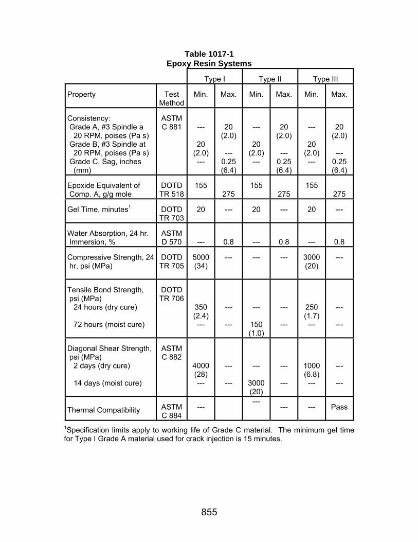
855
Table 1017-1 Epoxy Resin Systems
Type I
Type II
Type III
Property
Test
Method
Min.
Max.
Min.
Max.
Min.
Max.
Consistency: Grade A, #3 Spindle a 20 RPM, poises (Pa·s) Grade B, #3 Spindle at 20 RPM, poises (Pa·s) Grade C, Sag, inches (mm)
ASTM C 881
---
20 (2.0) ---
20 (2.0)
---
0.25 (6.4)
---
20 (2.0) ---
20 (2.0)
---
0.25 (6.4)
---
20 (2.0) ---
20 (2.0)
---
0.25 (6.4)
Epoxide Equivalent of Comp. A, g/g mole
DOTD TR 518
155
275
155
275
155
275 Gel Time, minutes1
DOTD TR 703
20
---
20
---
20
---
Water Absorption, 24 hr. Immersion, %
ASTM D 570
---
0.8
---
0.8
---
0.8 Compressive Strength, 24 hr, psi (MPa)
DOTD TR 705
5000 (34)
---
---
---
3000 (20)
---
Tensile Bond Strength, psi (MPa) 24 hours (dry cure) 72 hours (moist cure)
DOTD TR 706
350 (2.4) ---
---
---
---
150 (1.0)
---
---
250 (1.7) ---
---
---
Diagonal Shear Strength, psi (MPa) 2 days (dry cure) 14 days (moist cure)
ASTM C 882
4000 (28) ---
---
---
---
3000 (20)
---
---
1000 (6.8) ---
---
---
Thermal Compatibility
ASTM C 884
---
--- ---
---
Pass
1Specification limits apply to working life of Grade C material. The minimum gel time for Type I Grade A material used for crack injection is 15 minutes.
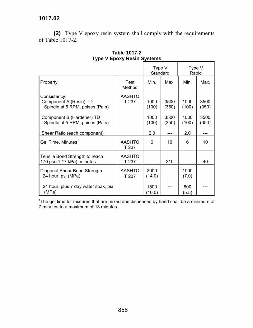
1017.02
856
(2) Type V epoxy resin system shall comply with the requirements of Table 1017-2.
Table 1017-2 Type V Epoxy Resin Systems
Type V
Standard
Type V Rapid
Property
Test
Method
Min.
Max.
Min.
Max.
Consistency: Component A (Resin) TD Spindle at 5 RPM, poises (Pa·s) Component B (Hardener) TD Spindle at 5 RPM, poises (Pa·s) Shear Ratio (each component)
AASHTO
T 237
1000 (100)
1000 (100)
2.0
3500 (350)
3500 (350)
---
1000 (100)
1000 (100)
2.0
3500 (350)
3500 (350)
---
Gel Time, Minutes1
AASHTO
T 237
6
10
6
10
Tensile Bond Strength to reach 170 psi (1.17 kPa), minutes
AASHTO
T 237
---
210
---
40 Diagonal Shear Bond Strength 24 hour, psi (MPa) 24 hour, plus 7 day water soak, psi (MPa)
AASHTO
T 237
2000 (14.0)
1500 (10.0)
---
---
1000 (7.0)
800 (5.5)
---
---
1The gel time for mixtures that are mixed and dispensed by hand shall be a minimum of 7 minutes to a maximum of 13 minutes.
857
Section 1018 Miscellaneous Materials
1018.01 WATER FOR CEMENT. Water suitable for human consumption may be used in mixtures with portland cement without testing. Water obtained from other sources, when tested in accordance with AASHTO T 26 shall meet the following requirements.
Percent by Weight
(Mass)(Max.) Alkali Solids (Organic) Solids (Inorganic) Salt (NaCl) Sugar, Oil, or Acid
0.1 0.1 0.4 0.5 0.0
1018.02 CALCIUM CHLORIDE. Calcium chloride shall comply with AASHTO M 144. 1018.03 LIME. Lime shall be hydrated lime or quicklime from an approved source listed in QPL 34 and shall comply with AASHTO M 216 when tested in accordance with DOTD TR 525 with the following exceptions: (a) Maximum free moisture shall be 1.50 percent for hydrated lime. (b) Quicklime shall contain no more than 8 percent MgO by weight (mass) of total material. Quicklime shall be protected from contact with moisture prior to testing, shall be free flowing and graded so that 100 percent will pass a 3/8 inch (9.5 mm) sieve. When the quicklime is to be used in a slurry the gradation shall be a minimum of 95 percent passing the 3/4 inch (19 mm) sieve. 1018.04 FRAMES, GRATES AND COVERS FOR MANHOLES, CATCH BASINS, AND JUNCTION BOXES. Metal units shall comply with the following requirements: (a) Gray iron castings shall comply with Subsection 1013.06. (b) Steel castings shall comply with Subsection 1013.05. (c) Malleable iron castings shall comply with Subsection 1013.06.

1018.04
858
(d) Galvanizing shall comply with ASTM A 123. 1018.05 GROUND ROD ASSEMBLIES. Ground rod assemblies suitable for grounding fences and other applicable grounding requirements shall meet the following requirements: (a) Ground rods shall be a minimum 5/8 inch 16 mm nominal diameter copper weld steel rod with a minimum length of 8 feet (2.4 m). (b) Ground wire shall be an AWG No. 6 (13.30 sq mm) solid copper conductor firmly attached in such a manner that fence fabric, barbed wire, metal post and ground rod are electrically connected. (c) Mechanical connectors for attaching ground wire to fence fabric, barbed wire and metal posts shall be solid copper alloy UL approved. Coated steel hardware will not be permitted. (d) Mechanical connectors for attaching ground wire to ground rods shall be solid copper alloy UL approved. 1018.06 PREFABRICATED MASONRY PADS. (a) Type A Pads: These pads shall be composed of multiple layers of 8-ounce (230 g) cotton duck impregnated and bound with high quality rubber compound, or of equally suitable materials compressed into resilient pads of uniform thickness after compressing and vulcanizing. Pads shall withstand 10,000 psi (70 MPa) compressive loads perpendicular to the plane of laminations. Load deflection properties in accordance with MIL-C-882C shall be the following maximum percentages of total pad thickness: 10 percent at 1,000 psi (7 MPa); 15 percent at 2,000 psi (14 MPa). When loaded to 1,500 psi (10 MPa), the permanent set, as load is removed in accordance with MIL-C-882C, shall be a maximum of 2.5 percent of the original "zero point" thickness. Shore "A" Durometer hardness shall be 90±5. The material shall not lose effectiveness throughout a temperature range of -65 to +150°F (-55 to +65°C). There shall be no visual evidence of damage or deterioration by effects of sunshine, humidity, salt spray, fungus and dust in accordance with MIL-E-5272C. Thickness shall not vary from that specified by more than 5 percent. (b) Type B Pads: These pads shall consist of fabric and rubber body made from new unvulcanized rubber and new fabric fibers in proper proportion to maintain strength and stability. The vulcanized and cured pad shall have a Shore "A" Durometer hardness of 80±10 and shall withstand a 10,000 psi (70 MPa) compressive load without excessive extrusion or detrimental reduction in thickness.
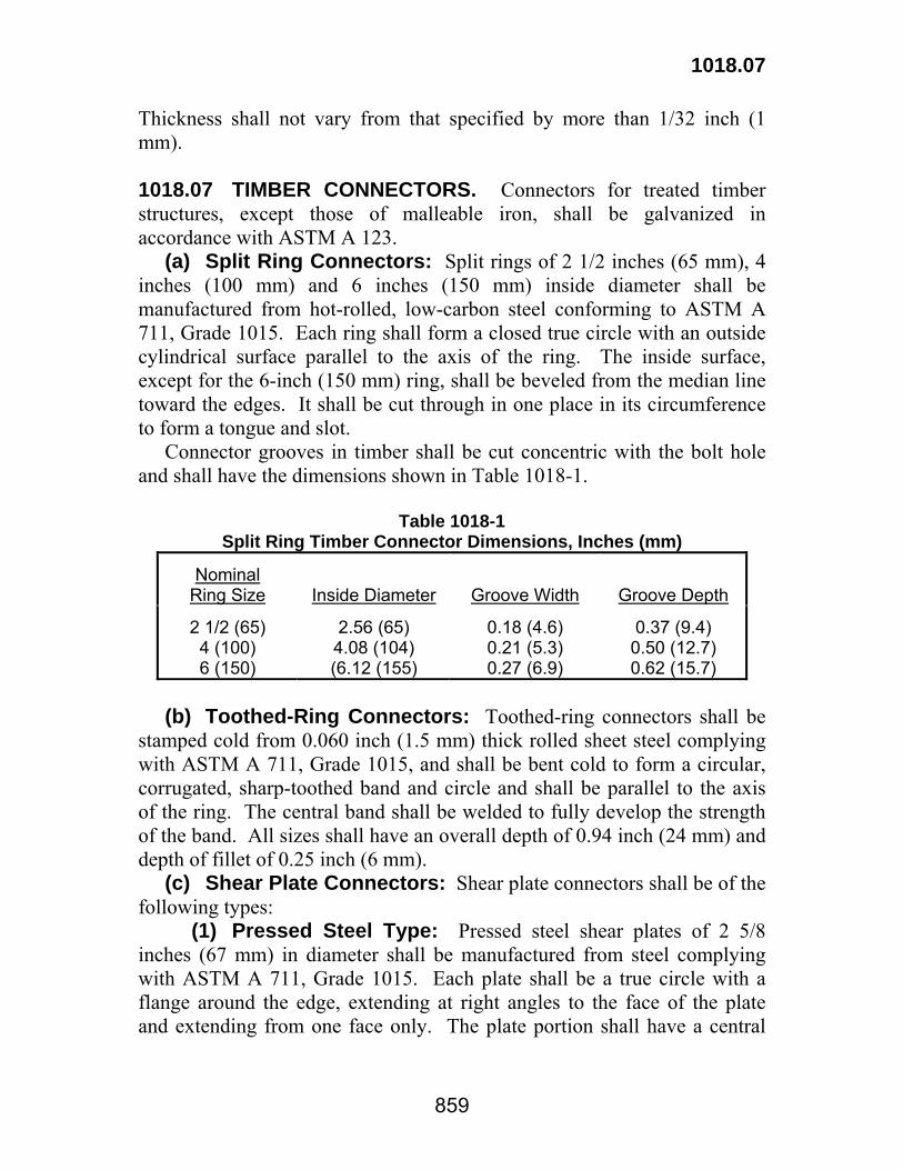
1018.07
859
Thickness shall not vary from that specified by more than 1/32 inch (1 mm). 1018.07 TIMBER CONNECTORS. Connectors for treated timber structures, except those of malleable iron, shall be galvanized in accordance with ASTM A 123. (a) Split Ring Connectors: Split rings of 2 1/2 inches (65 mm), 4 inches (100 mm) and 6 inches (150 mm) inside diameter shall be manufactured from hot-rolled, low-carbon steel conforming to ASTM A 711, Grade 1015. Each ring shall form a closed true circle with an outside cylindrical surface parallel to the axis of the ring. The inside surface, except for the 6-inch (150 mm) ring, shall be beveled from the median line toward the edges. It shall be cut through in one place in its circumference to form a tongue and slot. Connector grooves in timber shall be cut concentric with the bolt hole and shall have the dimensions shown in Table 1018-1.
Table 1018-1 Split Ring Timber Connector Dimensions, Inches (mm)
Nominal
Ring Size
Inside Diameter
Groove Width
Groove Depth
2 1/2 (65) 4 (100) 6 (150)
2.56 (65) 4.08 (104) (6.12 (155)
0.18 (4.6) 0.21 (5.3) 0.27 (6.9)
0.37 (9.4) 0.50 (12.7) 0.62 (15.7)
(b) Toothed-Ring Connectors: Toothed-ring connectors shall be stamped cold from 0.060 inch (1.5 mm) thick rolled sheet steel complying with ASTM A 711, Grade 1015, and shall be bent cold to form a circular, corrugated, sharp-toothed band and circle and shall be parallel to the axis of the ring. The central band shall be welded to fully develop the strength of the band. All sizes shall have an overall depth of 0.94 inch (24 mm) and depth of fillet of 0.25 inch (6 mm). (c) Shear Plate Connectors: Shear plate connectors shall be of the following types: (1) Pressed Steel Type: Pressed steel shear plates of 2 5/8 inches (67 mm) in diameter shall be manufactured from steel complying with ASTM A 711, Grade 1015. Each plate shall be a true circle with a flange around the edge, extending at right angles to the face of the plate and extending from one face only. The plate portion shall have a central
1018.07
860
bolt hole and two small perforations on opposite sides of the hole and midway from the center and circumference. (2) Malleable Iron Type: Malleable iron shear plates of 4-inch (100 mm) diameter shall be manufactured according to ASTM A 47, Grade 32510 (ASTM A 47M, Grade 22010). Each casting shall consist of a perforated round plate with a flange around the edge extending at right angles to the face of the plate and projecting from one face only. The plate portion shall have a central bolt hole reamed to size with an integral hub concentric to the bolt hole and extending from the same face as the flange. (d) Claw-Plate Connectors: Claw-plate connectors of 2 5/8 inches (67 mm), 3 1/8 inches (80 mm) and 4 inches (100 mm) in diameter shall be of malleable iron, manufactured according to ASTM A 47, Grade 32510 (ASTM A 47M, Grade 22010). Each claw-plate shall consist of a perforated circular flanged plate with three-sided teeth arranged about the perimeter of one face. The male plate shall have integral cylindrical hubs on both faces concentric to a bolt hole through the center of the plate. The female plate shall be flat on the side opposite the teeth, but shall have an integral cylindrical hub concentric to the central bolt hole and on the face with the teeth. (e) Spike-Grid Connectors: Spike-grid connectors shall be manufactured according to ASTM A 47, Grade 32510 (ASTM A 47M, Grade 22010). They shall consist of four rows of opposing spikes forming a 4 1/8 inch (105 mm) square grid with 16 teeth which are held in place by fillets. Fillets for the flat grid in cross section shall be diamond shaped. Fillets for single and double curve grids shall be increased in depth to allow for curvature and shall maintain a thickness between sloping faces on fillets equal to the width of the fillet. 1018.08 HARDWARE AND STRUCTURAL SHAPES. (a) Hardware: Bolts shall conform to ASTM A 307. Dowels shall conform to AASHTO M 270, Grade 36 (M 270M, Grade 250) except the maximum tensile strength shall be 88,000 psi (605 MPa). Washers shall be cast ogee gray iron or malleable castings. A Standard washer shall be used under heads of lag screws. Machine bolts may have either square or hex heads and nuts. Nails shall be cut or round wire of standard form. Spikes shall be cut wire or boat spikes. Bridge hardware shall be galvanized in accordance with ASTM A 153 or ASTM A 123 or by an approved mechanical galvanizing process complying with ASTM B 695 that provides the same coating thickness.
1018.12
861
(b) Structural Shapes: Structural shapes, rods and plates shall be of structural steel complying with Section 1013. (c) Electrical Hardware: Hardware for electrical apparatus shall comply with ASTM A 193, Grade B8 (bolts and studs) and ASTM A 194, Grade 8 or 8A (nuts). (d) Eyebolts: Eyebolts shall comply with ASTM A 489. 1018.09 RIGID METAL ELECTRICAL CONDUIT. Rigid metal electrical conduit shall comply with ANSI C 80.1 or ANSI C 80.5. 1018.10 ELECTRICAL CONDUCTORS. Electrical conduction shall comply with IPCEA Publication No. S-19-81, IPCEA Publication S-66-524, and IPCEA Publication S-61-402. 1018.11 ALUMINUM PLATE FOR ELECTRICAL BOXES. Aluminum plate shall comply with ASTM B 209, Alloy 6061-T6. 1018.12 BARRICADE WARNING LIGHTS. (a) General: Types A, B and C barricade warning lights shall be in accordance with the MUTCD and shall be an approved product listed in QPL 16. (b) Markings: Each light submitted for approval and each light placed on a project shall have a permanently attached identification plate or other permanent markings with the following information: (1) Manufacturer's name (2) Model number (3) Type (4) Lens manufacturer and identification number (5) Circuit manufacturer and identification number (6) Bulb number (7) Minimum operating voltage required to conform to minimum intensity requirements (8) Year of manufacture (c) Certification: Prior to installation, the contractor shall furnish the engineer with the following information: (1) Material certification (Certificate of Compliance) (2) Proposed number of warning lights to be used, (3) Type (4) Trade name (5) Manufacturer's name and model number as contained in QPL 16

1018.12
862
The certification shall also state that each light assembly has been tested, is functioning properly and will be maintained in satisfactory working order. 1018.13 ROOFING PITCH. Roofing pitch shall comply with ASTM D 4586. 1018.14 ELASTOMERIC BRIDGE BEARING PADS. (a) General: Elastomeric bridge bearing pads shall be either plain (consisting of elastomer only) or laminated (consisting of layers of elastomer separated by nonelastic laminates. The elastomer portion of the compound used for bearings shall be 100 percent virgin chloroprene stock. Natural rubber, vulcanized rubber (natural or synthetic) or other synthetic rubber-like materials will not be acceptable. Nonelastic laminates shall be a nominal 1/16 inch (1.5 mm) thickness rolled steel sheets with a minimum yield strength of 33,000 psi (225 MPa). Elastomeric bridge bearing pads shall be an approved product listed in QPL 3. (b) Physical Properties of Elastomer: The elastomer compound for plain and laminated bearings shall be a virgin, low temperature Grade 2, polychloroprene complying with AASHTO M 251. In addition, the pad shall comply with Level II acceptance criteria of AASHTO M251. All tests shall be made on the finished product. Special molded or prepared specimens, where required, shall comply with the specimen preparation requirements of the test involved. (c) Manufacturing Requirements: Components of laminated bearing pads shall be molded into an integral unit. Edges of the nonelastic laminations shall be covered by a minimum of 1/8 inch (3 mm) of elastomer. Laminates shall be parallel with the bottom surface of the bearing, subject to the tolerances that follow. The preparation of elastomer compound prior to placement in the mold shall be such as to result in a homogeneous, finished bearing pad free of voids, blisters, cracks, folds, cuts, nonfills and any appearance of layers or ply separation on the surface or within the pad. Plain bearing pads may be molded individually or cut to length from previously molded strips or slabs. No pads shall be formed from the lamination of previously cured sheets or slabs. Finish of cut surfaces shall be at least as smooth as ANSI No. 250 finish. Each bearing pad shall be marked with the manufacturer's identification number in such manner as to remain legible until the bearing pad is placed

1018.15
863
in the structure. This number shall identify the batch from which it was produced. A batch is defined as the quantity of compound produced from each separate mixture of ingredients. (d) Appearance and Dimensions: Flash tolerance and appearance shall comply with Drawing RMA F3-T.063 of the RMA Rubber Products Handbook as published by the Rubber Manufacturers Association, Inc. For both plain and laminated bearings, permissible variations from specified dimensions and configuration shall be in accordance with AASHTO M251.
Tolerance
Inches (mm) Variation from Plane Parallel to Theoretical Surface Individual Nonelastic Laminates (determined by measurements at edges of bearing) Thickness of Nonelastic Laminates
±1/8 (±3) -0, +1/16 (-0, +1.5)
(e) Load Testing: For laminated bearings, each bearing shall be subjected to an average compression test loading of 1,500 psi (10 MPa) by the manufacturer. The performance of each bearing will be considered satisfactory if there is no visible evidence of bond failure or other damage to the bearing because of this loading. The Department will verify that pads meet this requirement by means of random testing. (f) Certification: Prior to installation, the contractor shall furnish the Materials Engineer Administrator with a notarized material Certificate of Analysis and a list of: (1) the proposed number of laminated bearing pads to be used itemized by type and size. (2) manufacturer's name and identification number. (3) the state project number. The certification shall also state that each laminated bearing pad shipped has been load tested and found to comply with specifications as described in Subsection 1018.14(e). It shall also state that the steel laminates in each pad are aligned as required in Subsection 1018.14(d). 1018.15 FLY ASH. Fly ash shall be from an approved source listed in QPL 50 and shall comply with AASHTO M 295 for Class C and Class F only.
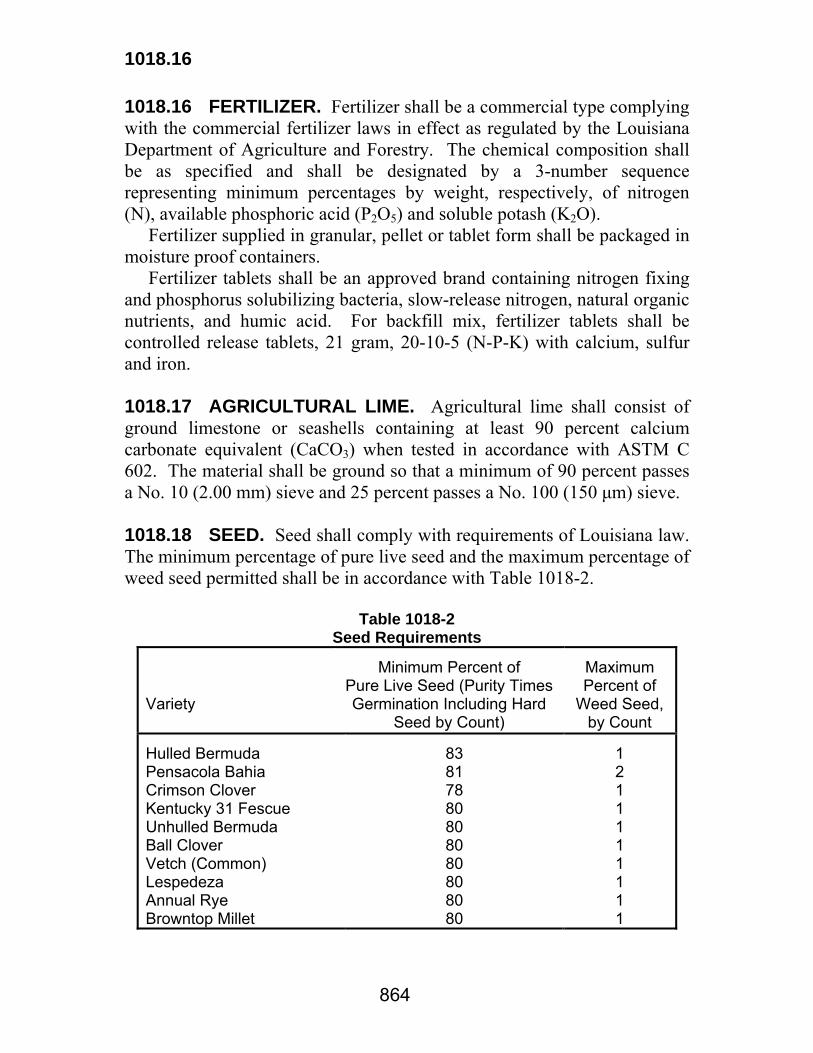
1018.16
864
1018.16 FERTILIZER. Fertilizer shall be a commercial type complying with the commercial fertilizer laws in effect as regulated by the Louisiana Department of Agriculture and Forestry. The chemical composition shall be as specified and shall be designated by a 3-number sequence representing minimum percentages by weight, respectively, of nitrogen (N), available phosphoric acid (P2O5) and soluble potash (K2O). Fertilizer supplied in granular, pellet or tablet form shall be packaged in moisture proof containers. Fertilizer tablets shall be an approved brand containing nitrogen fixing and phosphorus solubilizing bacteria, slow-release nitrogen, natural organic nutrients, and humic acid. For backfill mix, fertilizer tablets shall be controlled release tablets, 21 gram, 20-10-5 (N-P-K) with calcium, sulfur and iron. 1018.17 AGRICULTURAL LIME. Agricultural lime shall consist of ground limestone or seashells containing at least 90 percent calcium carbonate equivalent (CaCO3) when tested in accordance with ASTM C 602. The material shall be ground so that a minimum of 90 percent passes a No. 10 (2.00 mm) sieve and 25 percent passes a No. 100 (150 μm) sieve. 1018.18 SEED. Seed shall comply with requirements of Louisiana law. The minimum percentage of pure live seed and the maximum percentage of weed seed permitted shall be in accordance with Table 1018-2.
Table 1018-2 Seed Requirements
Variety
Minimum Percent of
Pure Live Seed (Purity Times Germination Including Hard
Seed by Count)
Maximum Percent of
Weed Seed, by Count
Hulled Bermuda Pensacola Bahia Crimson Clover Kentucky 31 Fescue Unhulled Bermuda Ball Clover Vetch (Common) Lespedeza Annual Rye Browntop Millet
83 81 78 80 80 80 80 80 80 80
1 2 1 1 1 1 1 1 1 1
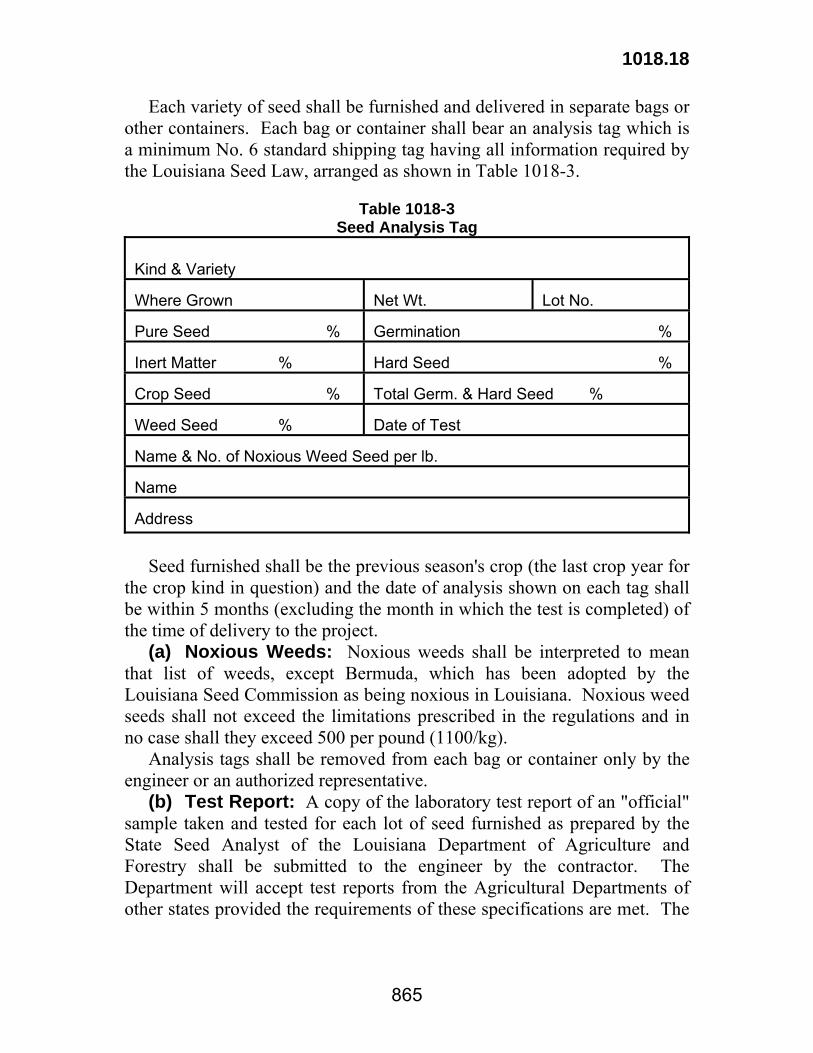
1018.18
865
Each variety of seed shall be furnished and delivered in separate bags or other containers. Each bag or container shall bear an analysis tag which is a minimum No. 6 standard shipping tag having all information required by the Louisiana Seed Law, arranged as shown in Table 1018-3.
Table 1018-3
Seed Analysis Tag Kind & Variety Where Grown
Net Wt.
Lot No.
Pure Seed %
Germination %
Inert Matter %
Hard Seed %
Crop Seed %
Total Germ. & Hard Seed %
Weed Seed %
Date of Test
Name & No. of Noxious Weed Seed per lb. Name Address
Seed furnished shall be the previous season's crop (the last crop year for the crop kind in question) and the date of analysis shown on each tag shall be within 5 months (excluding the month in which the test is completed) of the time of delivery to the project. (a) Noxious Weeds: Noxious weeds shall be interpreted to mean that list of weeds, except Bermuda, which has been adopted by the Louisiana Seed Commission as being noxious in Louisiana. Noxious weed seeds shall not exceed the limitations prescribed in the regulations and in no case shall they exceed 500 per pound (1100/kg). Analysis tags shall be removed from each bag or container only by the engineer or an authorized representative. (b) Test Report: A copy of the laboratory test report of an "official" sample taken and tested for each lot of seed furnished as prepared by the State Seed Analyst of the Louisiana Department of Agriculture and Forestry shall be submitted to the engineer by the contractor. The Department will accept test reports from the Agricultural Departments of other states provided the requirements of these specifications are met. The
1018.18
866
lot number on the analysis tag shall match the laboratory test report lot number. 1018.19 MULCH. Mulch shall consist of either tacked vegetative mulch or an approved fiber mulch product complying with the following: (a) Tacked Vegetative Mulch: Vegetation shall consist of pine straw, stems or stalks of oats, rye, rice, or other approved straws. The contractor may also use hay obtained from various legumes and grasses such as lespedezas, clover, vetches, soybeans, Bermuda, Dallis, carpet sedge, fescue or other approved legumes or grasses of any combination thereof. Straw or hay shall be reasonably dry and free from mold, Johnson grass or other noxious weeds. Vegetative mulch shall be tacked with one of the following: (1) Emulsified asphalt complying with Section 1002, or (2) An approved tacking agent for vegetative mulch listed in the Qualified Products List (QPL 72). The minimum allowable vegetation density for source approval of tacked vegetative mulch shall be 70 percent for clay soils and 60 percent for sandy soils when evaluated in accordance with the Texas Transportation Institute (TTI) Field Performance Testing Procedure of Selected Erosion Contol Products. (b) Fiber Mulch Products: Fiber mulch products shall be listed in the QPL 72 and consist of organic fiber mulches. The minimum allowable vegetation density for source approval of fiber mulch products shall be 70 percent for clay soils and 60 percent for sandy soils when evaluated in accordance with the TTI Field Performance Testing Procedure of Selected Erosion Control Products. 1018.20 SACKS FOR SACKED CONCRETE. Sacks for sacked concrete revetment shall be suitable new burlap bags. Burlap shall comply with AASHTO M 182. 1018.21 HARDWARE CLOTH. Hardware cloth shall comply with the requirements of ASTM A 740, have a minimum wire diameter of 0.041 inch (1.04 mm), and be constructed of 1/2 inch x 1/2 inch (12.5 mm x 12.5 mm) mesh galvanized in accordance with ASTM A 153. 1018.22 CONCRETE ANCHOR SYSTEMS. Concrete anchor systems shall consist of mechanical anchor devices, epoxy systems or other approved methods for anchoring fasteners to hardened concrete. These systems shall be approved products listed in QPL 40.
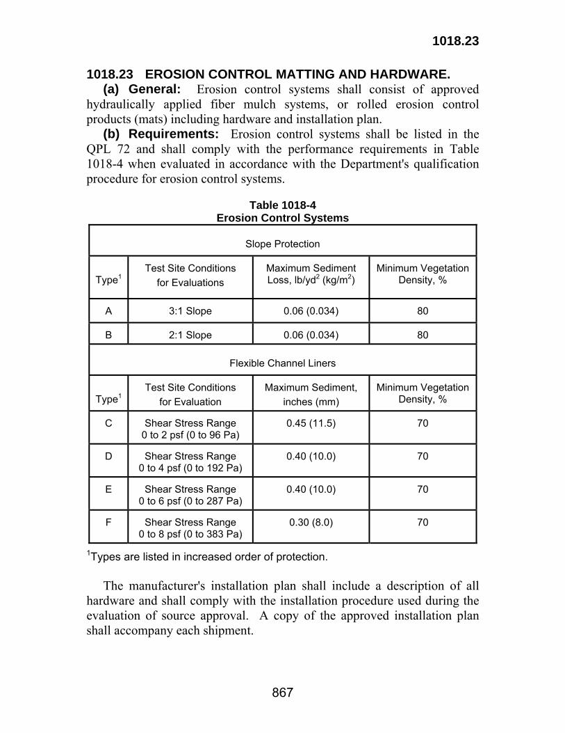
1018.23
867
1018.23 EROSION CONTROL MATTING AND HARDWARE. (a) General: Erosion control systems shall consist of approved hydraulically applied fiber mulch systems, or rolled erosion control products (mats) including hardware and installation plan. (b) Requirements: Erosion control systems shall be listed in the QPL 72 and shall comply with the performance requirements in Table 1018-4 when evaluated in accordance with the Department's qualification procedure for erosion control systems.
Table 1018-4
Erosion Control Systems
Slope Protection
Type1
Test Site Conditions
for Evaluations
Maximum Sediment Loss, lb/yd2 (kg/m2)
Minimum Vegetation
Density, %
A
3:1 Slope
0.06 (0.034)
80
B
2:1 Slope
0.06 (0.034)
80
Flexible Channel Liners
Type1
Test Site Conditions
for Evaluation
Maximum Sediment,
inches (mm)
Minimum Vegetation
Density, %
C
Shear Stress Range 0 to 2 psf (0 to 96 Pa)
0.45 (11.5)
70
D
Shear Stress Range
0 to 4 psf (0 to 192 Pa)
0.40 (10.0)
70
E
Shear Stress Range
0 to 6 psf (0 to 287 Pa)
0.40 (10.0)
70
F
Shear Stress Range
0 to 8 psf (0 to 383 Pa)
0.30 (8.0)
70
1Types are listed in increased order of protection. The manufacturer's installation plan shall include a description of all hardware and shall comply with the installation procedure used during the evaluation of source approval. A copy of the approved installation plan shall accompany each shipment.
1018.24
868
1018.24 FORM RELEASE AGENT. Form release agent for concrete shall be an approved product listed in QPL 29. 1018.25 MIX RELEASE AGENT FOR ASPHALTIC CONCRETE. Mix release agent for asphaltic concrete shall be an approved product listed in QPL 25. Diesel is not allowed as a mix release agent. 1018.26 NON-SHRINK GROUT. Non-shrink grout shall comply with ASTM C 1107 and shall be an approved product listed in QPL 47. 1018.27 GROUND GRANULATED BLAST-FURNACE SLAG: Grade 100 and grade 120 ground granulated blast-furnace slag shall be from an approved source listed on QPL 70 and shall comply with AASHTO M 302, except alkali content calculated as sodium oxide equivalent shall not exceed 0.60 percent by weight. 1018.28 MICROSILICA (SILICA FUME). Microsilica shall be from an approved source listed in QPL 80 and shall comply with AASHTO M-307. 1018.29 WATER MANAGEMENT GEL: Water management gel shall consist of an acrylamide copolymer gel with the ability to retain and release available water to the root zone. The manufacturer's recommended amount of water management gel shall be mixed with the required amount of backfill soil per plant before backfilling. 1018.30 MYCORRHIZAL INOCULANT: Mycorrhizal inoculant shall consist of live spores and/or root fragments or mycelium of Vesicular-Arbuscular (VA) Endomycorrhizal fungi and Ectomycorrhizal fungus and beneficial bacteria which have been chosen based on their ability to survive and influence plants over a broad pH range. Rhododendrons, Azaleas, and Laurels require ericoid Mycorrhizae. Each Endomycorrhizal Inoculant shall carry a supplier's guarantee of numbers of propagules per unit weight or volume of bulk material. If more than one fungal species is claimed by the supplier, the label shall include a guarantee for each species of Mycorrhizal fungus claimed. The project engineer will verify that the expiration date or shelf life of each container has not expired before approving its use.

869
Section 1019 Geotextile Fabric and Geocomposite Systems
1019.01 GEOTEXTILE FABRIC. (a) General Requirements: The geotextile fabric shall be composed of at least 85 percent by weight (mass) of polyolefins, polyesters, or polyamides. The geotextile fabric shall be resistant to chemical attack, rot and mildew and shall have no tears or defects which adversely alter its physical properties. When required, the geotextile fabric shall contain stabilizers and/or inhibitors added to the base material to make filaments resistant to deterioration due to ultraviolet and heat exposure. Edges of geotextile fabric shall be finished to prevent the outer yarn from pulling away from the fabric. Fibers of other composition may be woven into the geotextile fabric for reinforcing purposes. Durability of these fibers shall be equivalent to that of the geotextile fabric. Geotextile fabric rolls shall be furnished with an opaque, waterproof wrapping for protection against moisture and extended ultraviolet exposure prior to placement. Each roll shall be labeled or tagged with the manufacturer's name, date of manufacture, batch number, name of product. Unless otherwise specified on the plans or in the project specifications, the geotextile fabric shall be an approved product in QPL 61. (b) Detailed Requirements: The geotextile fabric shall comply with the requirements in Table 1019-1 and shall be utilized as follows unless otherwise specified:
Use Classes (1) Drainage:
Underdrains A, B, C or D Pipe and Precast Manhole Joints A, B, C or D
Weep Holes A, B, C or D Bedding Fabric B, C, or D Approach Slabs B, C, or D Fabric for Geocomposite Drainage Systems1 B, C, or D
(2) Stabilization:
Bulkheads C or D Flexible Revetments C or D
1019.01
870
Rip Rap D Railroad Crossings D Base Course D Subgrade Layer D Soil Stabilization C, D, or S
(3) Paving Fabric2: B or C (modified) (4) Silt Fencing:
Wire Supported F Self Supported G
1Refer to Subsection 1019.02 for additional requirements. 2Refer to Subsection 1019.03 for additional requirements.
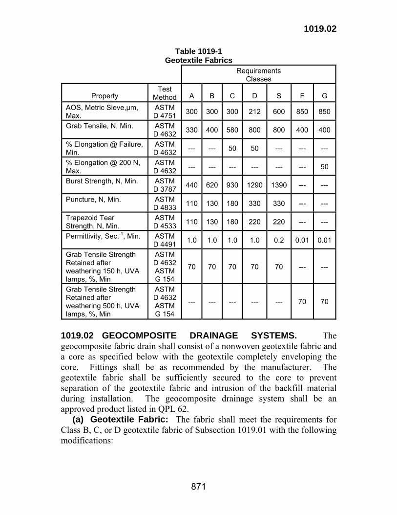
1019.02
871
Table 1019-1 Geotextile Fabrics
Requirements Classes
Property
Test Method
A
B
C
D
S
F
G
AOS, Metric Sieve,µm, Max.
ASTM D 4751 300 300 300 212 600 850 850
Grab Tensile, N, Min. ASTM D 4632 330 400 580 800 800 400 400
% Elongation @ Failure, Min.
ASTM D 4632 --- --- 50 50 --- --- ---
% Elongation @ 200 N, Max.
ASTM D 4632 --- --- --- --- --- --- 50
Burst Strength, N, Min. ASTM D 3787 440 620 930 1290 1390 --- ---
Puncture, N, Min. ASTM D 4833 110 130 180 330 330 --- ---
Trapezoid Tear Strength, N, Min.
ASTM D 4533 110 130 180 220 220 --- ---
Permittivity, Sec.-1, Min. ASTM D 4491 1.0 1.0 1.0 1.0 0.2 0.01 0.01
Grab Tensile Strength Retained after weathering 150 h, UVA lamps, %, Min
ASTM D 4632 ASTM G 154
70 70 70 70 70 --- ---
Grab Tensile Strength Retained after weathering 500 h, UVA lamps, %, Min
ASTM D 4632 ASTM G 154
--- --- --- --- --- 70 70
1019.02 GEOCOMPOSITE DRAINAGE SYSTEMS. The geocomposite fabric drain shall consist of a nonwoven geotextile fabric and a core as specified below with the geotextile completely enveloping the core. Fittings shall be as recommended by the manufacturer. The geotextile fabric shall be sufficiently secured to the core to prevent separation of the geotextile fabric and intrusion of the backfill material during installation. The geocomposite drainage system shall be an approved product listed in QPL 62. (a) Geotextile Fabric: The fabric shall meet the requirements for Class B, C, or D geotextile fabric of Subsection 1019.01 with the following modifications:
1019.02
872
Property Test Method Requirements Elongation, %, Min. ASTM D 4632 20 Sewn Seam Strength (Fabric to Fabric), kN/m width, Min. ASTM D 4437 2600 (b) Cores for Wall Drains (Single Sided): The core shall be a flexible, solid-backed, rectangular design made of a polyolefin material not sensitive to moisture. The geocomposite design shall allow drainage of water from one side only. The core shall consist of supports having a minimum height of 5/16 inch (8 mm) upon which the fabric shall be securely fastened. The cross section open area of the core which will allow the passage of water shall be a minimum of 40 percent. The core shall meet the following requirements:
Property Test Method Requirements Compressive Strength, kPa @ 20% Max. deflection, Min. ASTM D 1621 380 1019.03 PAVING FABRIC. In addition to the specifications for Class B or C geotextile fabric of Subsection 1019.01, the paving fabric shall also comply with the following requirements:
Property Test Method Requirements Asphalt Retention, L/sq m AASHTO M 288 0.9 Change in Area at 135°C, %, Max. AASHTO M 288 15.0

873
Section 1020 Traffic Signals
1020.01 TRAFFIC SIGNAL HEADS. (a) General Requirements: Traffic signal sections, beacon sections and pedestrian signal sections shall be of the adjustable type. Materials and construction of each section shall be the same. Signals shall be constructed for either 8 or 12-inch (200 mm or 300 mm) lens in accordance with the plans. Signal sections shall have three to five sections per face and beacon sections have only one section per face. Signal sections and associated brackets shall be finished inside and out with two coats of high grade green enamel (Outdoor Advertising Association No. 144) with each coat independently baked. Visors shall be coated green on the outside and black on the inside. Edges shall be deburred and smooth with no sharp edges. (b) Housing, Housing Doors, and Visors: Housing and doors shall be constructed of cast aluminum conforming to ASTM B 85 or B 108 with a minimum tensile strength of 17,000 psi (117 MPa). Hardware for the signals, such as hinges, locking devices, screws, bolts, etc., shall be stainless steel. (1) Housing: Housing shall be sectional and each face shall consist of as many sections as there are optical units, with a suitable top and bottom. Sections shall be rigidly and securely fastened together in a manner that provides mechanical integrity and a weatherproof optical unit. Each face shall be provided with round openings (slip-fit for 2-inch (50 mm) opening) in the top and bottom so that it may be rotated 360 degrees about its axis as a complete unit between waterproof supporting brackets or trunnions and be capable of being directed and locked at 5 degrees intervals. Serrations, detents, bolts, or similar locking devices are required. Friction will not be an acceptable lock. These locks shall be such that any face will resist a torque of 20 ft-lb (27 N·m) when assembled in accordance with the manufacturer's recommendations. The portion of the housing adjacent to the bracket shall be reinforced to have sufficient strength against breakage from shock. Seals, gaskets, labyrinths, or a suitable combination shall be provided at bracket attachment points and at section joints to ensure water shedding. Supporting brackets or trunnions shall be used at the top and bottom of section assemblies to rigidly support all faces.
1020.01
874
The bracket at the supported end of the signal section shall be 1 1/2 inch (38 mm) conduit or a conduit with an equivalent inside clearance for wiring. The bracket at the opposite end of the section may be either the same as the top or solid. A set screw engaging a drilled hole shall be provided at each joint on the bracket where conduit type joints are used or an equivalent locking device shall be provided. A 6-position terminal block for connection of wires from the socket and incoming wires from signal circuits shall be provided in the center section of the signal housing and shall include provisions for grounding. (2) Housing Doors: Housing doors shall contain locking devices which can be operated without tools. Door hinge pins shall be designed so that the door will not become disconnected from housing when open, regardless of signal position. Doors shall be field removable. Weather resisting, mildew-proof neoprene or silicone rubber sponge gasketing between the body of the housing and the doors shall be provided that will exclude dust and moisture. (3) Visors: Each signal section shall have a visor in accordance with the plans which tilts downward approximately 8 degrees from the horizontal. Visors shall be constructed of aluminum alloy sheet not less than 0.05 inch (1.3 mm) (No. 18 Gage) thick, or plastic (when specified). Visors shall be the standard Type A as shown on the plans. Type B tunnel visors shall be used where louvers are shown on the plans. Louvers shall be five vane and painted flat black. Visors shall be designed to fit tightly to the door and shall not permit any filtration of light between door and visor. Visors for pedestrian signals shall be Type A and shall encompass the tops and sides of the signal face and be a shape and size to adequately shield the face from external light sources. (c) Optical Unit: The optical unit shall consist of lens, reflector, lamp socket and lamp. The optical unit and visor shall be designed as a unit to eliminate the return of outside sunlight from entering the unit from above the horizontal (known as sun phantom). The optical unit shall be designed and assembled so that no light can escape from one indication to another. (1) Reflectors: Reflectors shall be rigidly mounted in the housing to assume proper alignment and arranged to be easily swung out of the housing and away from the door to provide access to the interior of the housing. An approved neoprene or rubber gasket shall be placed between the reflector and lens to ensure a dust tight seal. The gasket shall not be detrimental to the optical performance of the signal.
1020.01
875
Reflectors shall be made of specular Alzak Aluminum spun or punched from metal not less than 0.025-inch thick (650 μm), equipped with a bead or flange on the outer edge to stiffen the reflector and ensure trueness of shape. The thickness of the anodic coating shall be a minimum of 0.0003 inches (7.5 μm). The reflecting surface shall be free of flaws, scratches, defacements or mechanical distortion. (2) 12-Inch (300 mm) LED Traffic Signal Lamp Unit (Mast Arm and Span Wire Mount): a. General: The 12-inch (300 mm) LED traffic signal lamp unit shall be used in new traffic signal heads or as a retrofited replacement for existing incandescent signal lamps. No special tools will be required for installation. When used as a retrofitted replacement for existing incandescent signal lamps, the 12-inch (300 mm) LED traffic signal lamp unit shall fit into existing traffic signal housings without modifications. If proper orientation of the LED traffic signal lamp unit is required for optimum performance, prominent and permanent directional marking(s), such as an “UP arrow”, for correct indexing and orientation shall exist on the unit. The manufacturer’s name, individual serial number, manufactured date, model number, and batch number shall be permanently marked on the backside of the LED traffic signal lamp unit. A label shall be placed on the unit certifying compliance to ITE standards. b. Physical and Mechanical Requirements: The LED traffic signal lamp unit shall be a single, self-contained device, not requiring on-site assembly for installation into a new or existing traffic signal housing. The assembly and manufacturing process for the LED traffic signal lamp unit assembly shall be such as to assure all internal LED and electronic components are adequately supported to withstand mechanical shock and vibration from high winds and other sources. Each LED traffic signal lamp unit shall be comprised of a UV stabilized polymeric outer shell, multiple LED light source, and a regulated power supply. LEDs are to be mounted on a polycarbonate positioning plate or conformally coated printed circuit (PC) board. The external lens shall be smooth on the outside to prevent excessive dirt/dust buildup. The optical lens/appearance of the lamp shall reflect a light distribution look similar to that of an incandescent lamp. c. Optical and Light Output Requirements: The LEDs shall be manufactured using AlInGaP (Aluminum-Indium-Gallium-
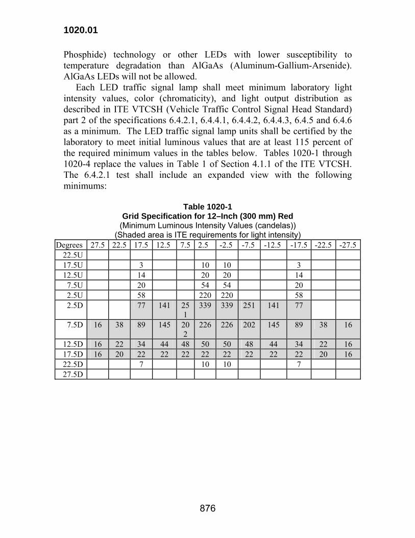
1020.01
876
Phosphide) technology or other LEDs with lower susceptibility to temperature degradation than AlGaAs (Aluminum-Gallium-Arsenide). AlGaAs LEDs will not be allowed. Each LED traffic signal lamp shall meet minimum laboratory light intensity values, color (chromaticity), and light output distribution as described in ITE VTCSH (Vehicle Traffic Control Signal Head Standard) part 2 of the specifications 6.4.2.1, 6.4.4.1, 6.4.4.2, 6.4.4.3, 6.4.5 and 6.4.6 as a minimum. The LED traffic signal lamp units shall be certified by the laboratory to meet initial luminous values that are at least 115 percent of the required minimum values in the tables below. Tables 1020-1 through 1020-4 replace the values in Table 1 of Section 4.1.1 of the ITE VTCSH. The 6.4.2.1 test shall include an expanded view with the following minimums:
Table 1020-1 Grid Specification for 12–Inch (300 mm) Red
(Minimum Luminous Intensity Values (candelas)) (Shaded area is ITE requirements for light intensity)
Degrees 27.5 22.5 17.5 12.5 7.5 2.5 -2.5 -7.5 -12.5 -17.5 -22.5 -27.522.5U 17.5U 3 10 10 3 12.5U 14 20 20 14 7.5U 20 54 54 20 2.5U 58 220 220 58 2.5D 77 141 25
1 339 339 251 141 77
7.5D 16 38 89 145 202
226 226 202 145 89 38 16
12.5D 16 22 34 44 48 50 50 48 44 34 22 16 17.5D 16 20 22 22 22 22 22 22 22 22 20 16 22.5D 7 10 10 7 27.5D

1020.01
877
Table 1020-2 Grid Specification for 12–Inch (300 mm) Green and Yellow
(Minimum Luminous Intensity Values (candelas)) (Shaded area is ITE requirements for light intensity)
Degrees 27.5 22.5 17.5 12.5 7.5 2.5 -2.5 -7.5 -12.5 -17.5 -22.5 -27.522.5U 17.5U 7 20 20 7 12.5U 27 41 41 27 7.5U 41 108 108 41 2.5U 115 441 441 115 2.5D 154 283 501 678 678 501 283 154 7.5D 32 77 178 291 404 452 452 404 291 178 77 32
12.5D 32 44 69 89 97 101 101 97 89 69 44 32 17.5D 32 41 44 44 44 44 44 44 44 44 41 32 22.5D 14 20 20 14 27.5D
Table 1020-3
Arrow Indications (candelas/m²) Red Yellow Green
Arrow Indication 5 500 11 000 11 000 LEDs for arrow indications shall be spread evenly across the illuminated portion of the arrow area. Arrow LED traffic signal lamp units shall be tested in conformance with California Test 3001. Measured chromaticity coordinates of LED traffic signal lamp units shall conform to the chromaticity requirements of the following table, for a minimum period of 60 months, over an operating temperature range of -40ºF (-40ºC) to 165ºF (74ºC). Each LED traffic signal lamp unit shall meet the minimum requirements for light output for the entire range from 80 to 135 volts.
Table 1020-4 Chromaticity Standards
Red Y: not greater than 0.308, or less than 0.998x Yellow Y: not less than 0.411, nor less than 0.995 – x,
nor greater than 0.452 Green Y: not less than 0.506 – 0.519x, nor less than
0.150 + 1.068x, nor greater than 0.730 – x LED traffic signal lamp units tested shall be representative of typical production units. Optical testing shall be performed with LED traffic
1020.01
878
signal lamp units mounted in standard traffic signal section without visors or hood attached to the signal sections. After burn-in, LED traffic signal lamp units shall be tested for rated initial luminous intensity in conformance with the provisions contained herein above. Before measurement, LED traffic signal lamp units shall be energized at rated voltage, with 100 percent on-time duty cycle, for a time period of 30 minutes. Test results for this testing shall record the current, voltage, total harmonic distortion (THD) and power factor (PF) associated with each measurement. Photometric, luminous intensity and color measurements for yellow LED traffic signal lamp units shall be taken immediately after the units are energized. The ambient temperature for these measurements shall be 77ºF (25ºC). Test results for this testing shall record the current, voltage, total harmonic distortion (THD) and power factor (PF) associated with each measurement. d. Electrical: Each LED traffic signal lamp unit shall incorporate a regulated power supply designed to electrically protect the LEDs and maintain a safe and reliable operation. The power supply shall provide capacitor filtered DC regulated current to the LEDs in accordance with the LED manufacturer’s specification. Design of the power supply shall be such that the failure of an individual component or any combination of components cannot cause the LED traffic signal lamp unit to be illuminated after AC power is removed. The power supply must be current regulated. The LED traffic signal lamp unit shall operate on a 60Hz AC line voltage ranging from 80 volts RMS to 135 volts RMS. The circuitry shall prevent flickering over this voltage range. Nominal rated voltage for all measurements shall be 117 volts RMS. The LED traffic signal lamp unit shall be operationally compatible with all TS1, TS2, and 2070 controllers, conflict monitors with plus features, and malfunction management units. In the case of conflicts between specifications, the latest LADOTD specifications will control. A circuitry shall be provided that will shutdown the LED traffic signal lamp unit and power supply when 85 percent ITE light intensity specifications as amended herein are not satisfied. The manufacturer may be required to effectively demonstrate this feature. Each shipment shall be accompanied with a certified test report from an independent testing lab. Random testing of average production units shall be conducted to ensure compliance with specifications.

1020.01
879
Two, color coded, 36 in. long, 600 V, 18 AWG minimum jacketed wires, properly terminated to the LED traffic signal lamp unit to prevent moisture, dust, and other environmental substances from entering the unit, conforming to the National Electric Code, and rated for service at 221ºF (105ºC), shall be provided for an electrical connection. Individual LED’s shall be wired so that a catastrophic failure of one LED light source will result in the loss of only one LED light source. The LED traffic signal lamp unit shall operate with a minimum 0.90 power factor. Total harmonic distortion (current and voltage) induced into an AC power line by an LED traffic signal lamp unit shall not exceed 20 percent. LED traffic signal lamp units and associated on-board circuitry shall conform to the requirements in Federal Communications Commission (FCC) Title 47, SubPart B, Section 15 regulations concerning the emission of electronic noise. e. Environmental Requirements: The LED traffic signal lamp unit shall be rated for use in the ambient operating temperature range of -40ºF (-40ºC) to 165ºF (74ºC). The unit shall consist of a housing that is a sealed watertight enclosure that eliminates dirt contamination and allows for safe handling in all weather conditions. Moisture resistance testing shall be performed on LED traffic signal lamp units in conformance with the requirements in NEMA Standard 250-1991 for Type 4 enclosures. Evidence of internal moisture after testing shall be cause for rejection. f. Production Testing Requirements: Each new LED traffic signal lamp unit shall be energized for a minimum of 24 hours at an operating temperature of 140ºF (60ºC) in order to cause any electronic infant mortality to occur, and to ensure electronic component reliability prior to shipment. After the burn-in procedure is completed, each LED traffic signal lamp unit shall be tested by the manufacturer for rated initial intensity at rated operating voltage. g. Certifications: The contractor shall submit a test report certified by an independent laboratory that is certified to test in accordance with ITE standards that the LED traffic signal lamp unit model to be furnished meets ITE Standards for light distribution as amended herein, chromaticity, and power (consumption, power factor and harmonic distortion). h. Warranty: The manufacturer shall provide a written warranty against defects in material, workmanship, or intensity for LED traffic signal lamp units for a period of 60 months after their installation. The traffic signal lamp units shall be warranted to maintain, throughout the
1020.01
880
warranty period, minimum luminous intensity values that are shown in the tables in paragraph c above. During the warranty period the manufacturer may be required to test any LED traffic signal lamp unit that is suspected to not meet the minimum intensity requirements at no cost to the Department. Any LED traffic signal lamp unit that fails during the warranty period shall be replaced. Replacement LED traffic signal lamp units shall be provided within 5 days after receipt of failed LED traffic signal lamp units at no cost to the Department. The measured chromaticity coordinates of light emitting diode traffic signal lamp units shall conform to the requirements for chromaticity in Section 8.04 and Figure 1 of the ITE VTCSH over the temperature range of -40ºF (-40ºC) to 165ºF (74ºC). (3) Lamp Receptacle: Lamp receptacles shall be made of heat resisting materials designed to properly position a traffic signal lamp with means for correct filament positioning. Lamp receptacles shall be designed to properly position a Type A lamp in the 8-inch lens section and Type B lamp in the 12-inch (300 mm) lens section. The receptacle shall be provided with a lamp grip to prevent the lamp from working loose due to vibration. Provisions shall be made to permit rotation of the lamp so that the lead wires are up and securely fastened, but shall not permit any change of position of the socket with respect to the optical center of the reflector. The metal portion of the lamp receptacle shall be brass or copper. A suitable dust-tight gasket (not cork) shall be placed between reflector and lamp socket. Each lamp receptacle shall be provided with two color coded No. 18 or larger lead wires, Type TEW, 600-volt, AWM fixture wire with 3/64 inch (1.2 mm), 105°C rated thermoplastic insulation, securely fastened to the socket with sufficient length to reach the terminal block with the reflector fully open. The thermoplastic insulation shall, at 34°F (1°C), be capable of being wrapped 6 times around a 1-inch (25 mm) mandrel without damage to its insulating properties at rated voltage. Each lead shall have a terminal attached to its end, for connection to the terminal block in the signal housing with a screw driver. (4) Pedestrian Signals: Pedestrian indications shall attract the attention of and be readable to the pedestrian both day and night and at all distances from 10 feet (3 m) to the full width of the area to be crossed. The indicators shall be rectangular and shall consist of the International Symbol Indications "WALKING PERSON" and the "RAISED HAND." When illuminated, the "WALKING PERSON" indication shall be lunar white and the "RAISED HAND" indication shall be Portland Orange

1020.01
881
meeting ITE standards. All but the symbols shall be obscured by an opaque material. When not illuminated, the "WALKING PERSON" and "RAISED HAND" indications shall not be distinguishable by pedestrians at the far end of the crosswalk they control. (d) Brackets: Brackets for the assembly of 2-way, 3-way and 4-way signal sections shall be constructed to have the center of the attachment points arranged on a 8-inch (200 mm) radius. Attachment to signal head shall be made with 1 1/2-inch (38 mm) conduit or 3-bolt type fittings with a bolt length 1 1/2 inches (38 mm). Fittings at the center of the bracket shall have a removable lower plate for access to the wireway. The bracket at the supported end of the signal section shall be 1 1/2-inch (38 mm) conduit or a conduit with an equivalent inside clearance for wiring and a fitting with cover for access to the wire-way. The bracket at the opposite end of the section may be either the same as the top or solid. A set screw engaging a drilled hole shall be provided at each joint on the bracket where conduit type joints are used or an equivalent locking device shall be provided. The attachment point for mounting on the bracket shall be a 2-inch (50 mm) opening. When slip-fit is used, the section shall come complete with the necessary nuts and washers for 1 1/2-inch (38 mm) conduit. Provisions shall be made for a positive lock to prevent accidental bracket rotation. Locking may be accomplished by means of serrations, detents, set screws, or similar devices. Friction locking will not be acceptable. An acceptable alternative to the 1 1/2-inch (38 mm) conduit will be a tri-stud type fitting with appropriate washer. Tri-stud length shall be 1 1/2 inches (38 mm). Unused openings of signal sections shall be closed with a standard waterproof plug for a 1 1/2-inch (38 mm) opening. The minimum length of the plug shall be 1 1/2-inches (38 mm). Steel plugs shall be galvanized in accordance with ASTM A 153. The exposed portions of plugs shall be painted to match the color of the signal heads. Carbon steel components shall be galvanized in accordance with ASTM A 153. (e) Signal Mounts: Signal sections and beacon sections shall be as shown on the plans and shall be suitable for one of the following standard mounts, the type mount for each shall be specified in the plans. (1) Support Cable Mount: Support cable mounted signals shall come with a disconnect hanger and clamp described in Subsection 1020.01(g).
1020.01
882
(2) Pedestal Mount: Pedestal mounts shall be furnished with a slip fitting for placement on a 4-inch (100 mm) inside diameter pipe pedestal having set screws for correct alignment of the signal. Provisions for the entrance of signal cables shall be incorporated into the design of the bracket assembly. The bracket assembly shall incorporate a weatherproof terminal compartment or box with a removable cover allowing complete access. The box shall be a suitable size to accommodate, and shall come equipped with, a terminal strip with terminals equal to the number of signal indications in the signal heads plus one or more for common and for equipment ground. The terminal compartment shall be neat in appearance and shall be adjacent to or near the pedestal mount. In no case shall feed wires be required to pass through a signal section or face to reach the terminal compartment. A terminal compartment integral with the bracket will be permitted. (3) Mast Arm Mount: This mount shall be furnished and installed with an adjustable stainless steel strap or cable clamp, malleable clamp casting, tightening mechanism, vertical support tube, top and bottom signal head support with set screws, and bolts. The vertical support tube shall be a minimum of 5 feet (1.5 m) long. Supporting brackets, trunnions, and fittings shall be made of cast aluminum, steel, or cast iron. (4) Side Mount: This mount shall be furnished for attaching brackets to vertical supports as shown on the plans. The bracket mounting hub shall accept 1 1/2-inch (38 mm) conduit and provide for a wire opening equivalent to a 1 1/2-inch (38 mm) condulet. For timber pole installation, the side mounts shall have a vertical entrance for 1-inch (25 mm) conduit. (5) Flashing Beacon Signal Mount: The flashing beacon signal shall attach to the support cable by a bracket as shown on the plans. The bracket shall be provided with a cable entrance adapter with provisions for balancing and securing the signal. (f) Backplates: Backplates shall be designed to fit the combination of sections of each signal face. Backplates shall be flat aluminum alloy at least 0.05 inch (1.3 mm) (No. 18 gage) thick and shall withstand distortion in 70 mph (115 km/h) winds and shall be firmly attached to each signal face to withstand the above wind load and to permit the opening of any signal door independent from the other doors in the signal face. Width of backplates shall extend a minimum of 5 1/2 inches (140 mm) from the

1020.01
883
signal head in all directions or as specified on the plans. Backplates shall be furnished with an oven baked black enamel. (g) Disconnect Hanger for Traffic Signal Head: The hanger shall provide a means for connecting and disconnecting the signal head electrically and mechanically from signal support cable and span wire without use of tools. The hanger, with top and bottom attachments and clamps, shall not increase signal height from the span wire to the bottom of the signal by more than 6 inches (150 mm). The hanger shall be as shown on the plans and shall conform to the requirements of the clamp, housing and terminal block, plug, and adapter. (1) Clamp: The clamp shall be capable of attaching to a 1/4 inch to 7/16 inch (6 mm to 11 mm) support cable and shall attach to or be integral with a balance adjusting device and a suitable weatherproof entrance for signal cable. The support cable clamp shall utilize a minimum of two "J" or "U" type bolts 3/8 inch (M10) or larger. A 5/8 inch (16 mm) clevis type suspension clamp shall be provided with a 5/8-inch (16 mm) diameter. The balance adjustor shall be suitable for mating with a clevis-type clamp having a horizontal clearance of 5/8 inch (16 mm) and pin of 5/8 inch (16 mm). All steel shall be galvanized in accordance with ASTM A 153. (2) Housing: The housing and accessories shall be high-strength aluminum alloy and shall be equipped with a door of similar material. The door shall be held shut by a device operable with one hand without use of tools and shall not be easily removable. The door, when open, shall provide complete access to the interior of the housing and a device shall be included to hold the door open while working inside the hanger if it will not remain open. The housing shall be equipped with two or more weatherproofed openings for signal cable entrance. The openings shall be equipped with suitable bushings for cable protection. Cable entrances shall be capable of accommodating three signal cables 11/16 inch (18 mm) in diameter. No cable opening shall be less than 1 inch (25 mm) in diameter. The housing shall be provided with a permanently mounted clamping device to prevent the cable from twisting. The clamping device shall not damage the cable jacket, insulation, or break wires. The housing shall be provided with a 3 1/2-inch-by-3 1/2-inch (90 mm by 90 mm) cast aluminum flange adaptor as shown on the plans for connecting to the signal head or bracket.

1020.01
884
(3) Terminal Block and Plug: An easily accessible pressure type terminal block shall be located in the housing and shall accommodate from twelve or eighteen separate lines, as specified. Each terminal shall be permanently numbered for identification, shall accommodate a minimum of two AWG No. 12 conductors, and shall be sufficiently rugged to permit tightening for proper electrical connection without damaging the wire. The terminal block shall be wired to a multi-circuit female jack connector mounted in the housing and aligned in accordance with the plans. A minimum size No. 18 AWG wire, with 600-volt polyethylene or polyvinylchloride insulation, shall be used between the terminal strip and the jack connector. The numbered terminals on the terminal strip shall be wired to the corresponding numbered pin in the jack connector. A suitable male plug with clamp for the corresponding female jack connector shall be furnished and shall be equipped with 4 feet (1.2 m) of cabled leads for connection to the signal heads. Wire shall be No. 18 AWG, 600-volt polyethylene or polyvinylchloride insulated and neatly cabled. 1020.02 TRAFFIC DETECTORS AND ASSOCIATED EQUIPMENT. Loop detection shall be used for vehicle detection on actuated phases of signal operation. Pedestrian push-buttons shall be used as pedestrian detectors. (a) Loop Detectors: Detector units for signalized intersections are included as part of DOTD Traffic Control Standard 18A. Detector units required at remote vehicle detection locations shall comply with NEMA TS1, Section 15, with or without delay and extension timing as specified. Two types of inductive detector units are specified, those with and without the ability to delay and extend a call, NEMA Type 1 and Type 1 T. Detector units shall be suitable for accurate detection of vehicles from motorcycles to tractor-trailer combinations which ordinarily travel public streets and highways with sufficient conductive material, suitably located to permit recognition and response by the detector system. Detector units shall also comply with NEMA TS1, Section 15.2.6. (1) Size and Case: The amplifier case shall be constructed of rugged metallic material with a protective coating. A removable cover shall be provided to allow access to internal circuitry. The cover shall be removable with hand tools. (2) Connectors, Switches, and Fuses: Switches, connectors, and fuses shall be located on the front of the unit.
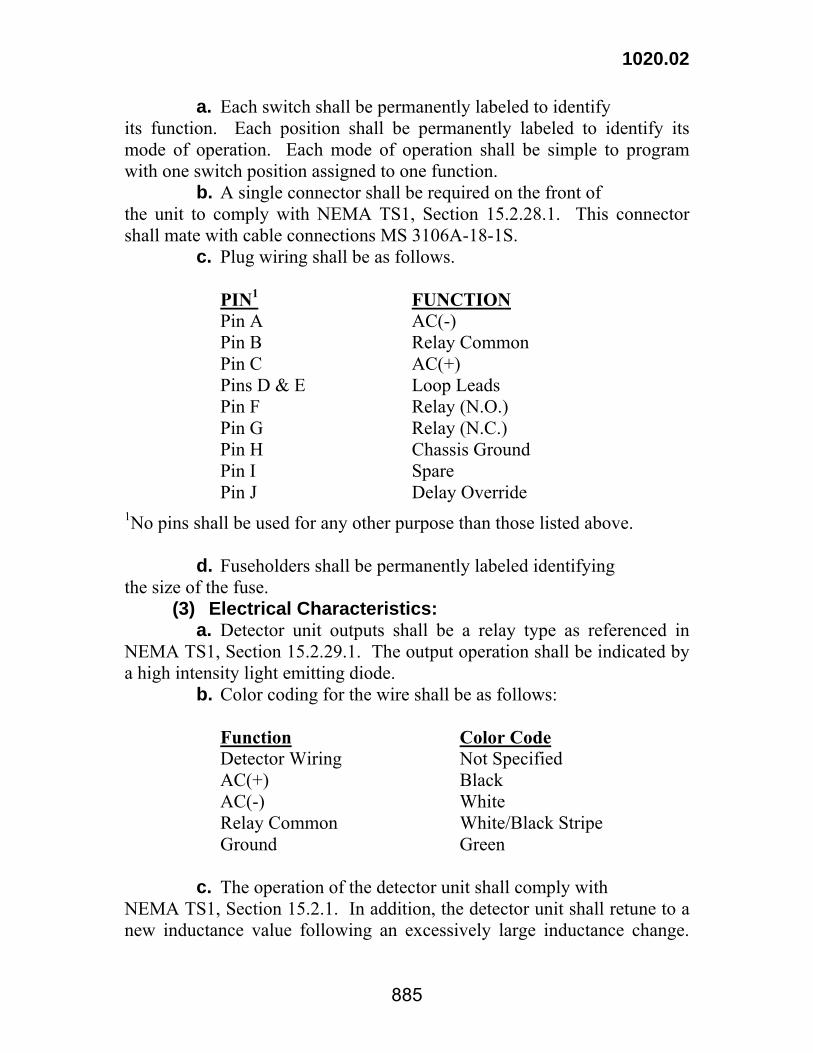
1020.02
885
a. Each switch shall be permanently labeled to identify its function. Each position shall be permanently labeled to identify its mode of operation. Each mode of operation shall be simple to program with one switch position assigned to one function. b. A single connector shall be required on the front of the unit to comply with NEMA TS1, Section 15.2.28.1. This connector shall mate with cable connections MS 3106A-18-1S. c. Plug wiring shall be as follows.
PIN1 FUNCTION Pin A AC(-) Pin B Relay Common Pin C AC(+) Pins D & E Loop Leads Pin F Relay (N.O.) Pin G Relay (N.C.) Pin H Chassis Ground Pin I Spare Pin J Delay Override
1No pins shall be used for any other purpose than those listed above. d. Fuseholders shall be permanently labeled identifying the size of the fuse. (3) Electrical Characteristics: a. Detector unit outputs shall be a relay type as referenced in NEMA TS1, Section 15.2.29.1. The output operation shall be indicated by a high intensity light emitting diode. b. Color coding for the wire shall be as follows:
Function Color Code Detector Wiring Not Specified AC(+) Black AC(-) White Relay Common White/Black Stripe Ground Green
c. The operation of the detector unit shall comply with NEMA TS1, Section 15.2.1. In addition, the detector unit shall retune to a new inductance value following an excessively large inductance change.
1020.02
886
d. When sensor loop and loop lead-in network falls outside the specifications in NEMA TS1, Section 15.2.13, the detector shall generate a fail safe continuous output in both presence and pulse modes. The continuous output shall remain until the memory is cleared by removing power or resetting. e. When specified, the detector unit shall have the ability to delay and extend a call to the controller. The Delay/Extension operations shall comply with NEMA TS1, Section 15.2.24. 1. The delay time shall begin when a vehicle enters the detection area until the call relay is closed representing an activation and shall be selectable in the range between 0 and 30 seconds. 2. The extension time shall begin timing when the vehicle leaves the detection area, continuing the activation for the selected time. The time shall be selectable in the range of 0 to 7 1/2 seconds. (4) The detector unit shall have at least three selectable frequencies which shall be visible at all times on the front of the detector unit. (5) The Sensitivity Control shall comply with NEMA TS1, Section 15.2.14 and Section 15.2.15. There shall be at least three selectable sensitivity ranges located on the front of the detector unit. The sensitivities shall be nominally 0.02 percent, 0.08 percent, and 0.32 percent change in total loop inductance. (6) The modes of operation shall comply with NEMA TS1, Section 15.2.17. There shall be two presence modes and one pulse mode. The selected mode shall be indicated at all times on the front of the detector unit. a. Long presence mode shall continue to detect the same vehicle within the detection area for at least 3 1/2 minutes for a Class 1 type test vehicle. b. Medium presence mode shall continue to detect the same vehicle within the detection area for at least 20 seconds for a Class 1 type test vehicle. (7) Fail Safe: The detector shall operate with the sensor loop shorted to ground or of poor quality. The unit shall generate a continuous call when returning failed sensor loop, failed detector unit, or power failure. (b) Pedestrian Pushbuttons: Pedestrian pushbuttons shall consist of a direct push type button and single momentary contact switch in a cast metal housing on which shall be attached the pushbutton sign shown in the plans. The cast metal housing shall include conduit fittings for 1/2-inch
1020.02
887
(13 mm) conduit on the back and bottom. Operating voltage for pedestrian pushbuttons shall not exceed 24 volts DC. The assembly shall be weatherproof and constructed so that it will be impossible to receive an electrical shock under any weather condition. When a pedestrian pushbutton is attached to a pole, the housing shall be shaped to fit the curvature of the standard or post to which it is attached to provide a rigid installation. When a pushbutton is to be mounted on top of a 2 1/2-inch (65 mm) post, the housing shall be provided with a slip-fitter fitting and screws for securing rigidly to the post. (c) Loop Detector Sealant: The loop detector sealant shall comply with Table 1020-5:

1020.02
888
Table 1020-5 Loop Detector Sealants
Cold Applied Single
Component Two Component
Rapid Set Slow Set
Physical Property Test Method
Hot Applied
Self
LevelingNon-Sag
Self Leveling
Non-Sag
Self Leveling
Non-Sag
Total Solids by weight,%, Min.
ASTM D 2834 60 60 60 60 60 60
Tack Free Time, hr, Max.
ASTM C 679 4 4 2 2 4 4
Rheological Properties
ASTM C 639 Type 1
Smooth surface Smooth
surface Smooth surface
Slump, mm ASTM D 2202 7.6 7.6 7.6
Extrusion Rate, mL/min, Min.
ASTM C 1183 50 50
Hardness shore A, Min.
ASTM D 2240 10 10 10 10 10 10
Penetration @ 25°C, Min.
ASTM D 5 60
Softening Point, °C, Min.
ASTM D 36 82
Asphalt Compatibility1
ASTM D 5329 pass pass pass pass pass pass pass
Pot Life, minutes, Min.
ASTM C 881 12 12 30 30
Dielectric Strength, 60 Hz, Short Time test, Electrode 1 in air @ 25°C kV/mm, Min.
ASTM D 149
13.8
13.8
13.8
13.8
13.8
13.8
13.8
Flex @-7°C, inch, 90° Bend
ASTM D 5329 pass pass pass pass pass pass pass
1Not applicable when used to seal portland cement concrete pavement 1020.03 TRAFFIC SIGNAL HARDWARE AND EQUIPMENT. (a) General: This Subsection defines the general requirements that shall apply to all hardware and equipment not specifically listed. When design tests are specified, documentation may be provided indicating that such tests have previously been satisfactorily completed. (b) Miscellaneous Hardware: Screws, nuts, and lock washers shall be stainless steel or galvanized in accordance with ASTM A 153. No self tapping screws shall be used unless approved.

1020.03
889
(c) Pedestal Anchor Bolts: Steel anchor bolts shall be as shown on the plans and shall be fitted with one hex nut and one washer. Nuts, washers, and anchor bolts shall be galvanized in accordance with ASTM A 153. (d) Support Cable: Support cable for interconnect and detector support cable shall be 1/4-inch (6 mm) outside diameter and signal support cable and guy wire shall be 3/8-inch (9 mm) outside diameter and shall comply with ASTM A 475, 7-strand Siemens-Martin grade with Class A coating. (e) Guy Components: Guying components and hardware shall be galvanized in accordance with ASTM A 123 and ASTM A 153. Guy clamps shall be steel, 3-bolt type, 6 inches (150 mm) in length, and of proper strand size to fit both sizes of cable. Clamp bolts shall have an upset shoulder fitting into the clamp plate. (f) Traffic Signal Cable: The cable shall be 600 volt insulated cable. Filler material, when used, shall be non-metallic, moisture resistant, non-hydroscopic, non-wicking, and non-absorbent. The conductors that are to be marked with tracer in addition to the solid color shall have the tracer as part of the insulation, ink marking is not acceptable. The outside jacket shall be smooth and shall not display patterns of the conductor lay on the outside of the jacket. The traffic signal cable shall be No. 14 AWG solid conductor. Interconnect cable shall be No. 16 AWG in the 24 conductor and 12 AWG in the 7 conductor. All material, color code, and testing shall comply with IMSA 20-1. The interconnecting cable between intersections for closed loop and telemetry operation shall be 6 pair IMSA 20-6. Loop lead-in cable shall be tinned No. 14 AWG stranded conductor, twisted pair with an overall shield. The cable shall comply with IMSA 50-2. Loop detector wire shall comply with IMSA 51-3 and shall be No. 16 AWG-19 strands/No. 29 AWG copper. Insulation shall be 0.080-inch XLPE. (g) Electrical Junction Box: Junction boxes shall be constructed of Class M concrete, cast iron or epoxy/sand composite, as shown on the plans. Class M concrete shall conform to Section 901. Reinforcement shall consist of welded wire fabric, 4-inch-by-4-inch (100 mm by 100 mm) No. 4/4 complying with Section 1009. Pull boxes may be cast-in-place or precast. Epoxy/sand composite boxes shall be manufactured in accordance with the plans. The composite material shall have a minimum compressive

1020.03
890
strength of 11,000 psi (75 MPa). The manufactured box shall have a minimum compressive strength of 50 psi (345 kPa) on the cover when installed on the box. 1020.04 POLES FOR TRAFFIC SIGNAL SYSTEMS. (a) Pedestal Support Signal Poles: The pole shall be in accordance with the plans. The base of the pedestal shall be cast iron or aluminum and shall be at least 16 inches (400 mm) wide at the bottom, at least 16 inches (400 mm) high and shall be octagonal. The upper end of the base shall be threaded to receive a 4-inch (100 mm) diameter pipe shaft. The base shall be designed so that it may be fastened to the foundation using 5/8-inch-by-16-inch (16 mm by 400 mm) anchor bolts located 90 degrees apart on the circumference of a circle 12 3/4 inches (325 mm) in diameter. The base shall contain a removable door to allow access to anchor bolts and to permit cable splicing. This door shall be fastened to the base using a hex head stainless steel screw into a threaded hole in the base. The shaft shall be 4 1/4 inches (108 mm) in inside diameter welded steel tubing with a minimum 1/8-inch (3 mm) wall thickness. The lower end of the shaft shall be welded to a 6-inch (150 mm) nipple to screw into the base. This shaft shall be a single piece of tubing. Pedestals shall be finished with at least one coat of rustproofing primer, applied to a clean surface and one coat of green enamel. The length of pedestal, shaft plus base, shall be a minimum of 8 feet (2.4 m). (b) Steel Signal Support Pole: (1) General: Poles and fittings shall be in accordance with the plans and shall be galvanized in accordance with ASTM A 123 and A 153. Poles shall be suitable for a minimum horizontal load of 4,000 pounds (1800 kg) applied 1 foot (300 mm) below the top of pole. (2) Pole Shaft: The pole shaft shall have a minimum base diameter of 11 inches (280 mm) and a maximum base diameter of 11 3/4 inches (295 mm). The pole shaft shall be tapered to approximately 7-inch (175 mm) diameter at the top. The pole shaft may have a round or octagonal cross section. A cap shall be used to cover the pole shaft top. The pole shall be designed so that its maximum deflection is as shown in Table 1020-6.
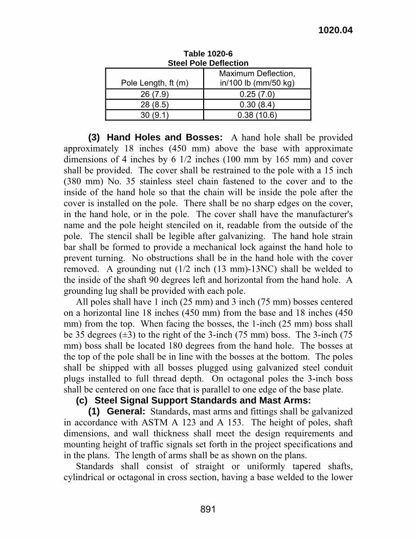
1020.04
891
Table 1020-6 Steel Pole Deflection
Pole Length, ft (m)
Maximum Deflection, in/100 lb (mm/50 kg)
26 (7.9) 0.25 (7.0) 28 (8.5) 0.30 (8.4) 30 (9.1) 0.38 (10.6)
(3) Hand Holes and Bosses: A hand hole shall be provided approximately 18 inches (450 mm) above the base with approximate dimensions of 4 inches by 6 1/2 inches (100 mm by 165 mm) and cover shall be provided. The cover shall be restrained to the pole with a 15 inch (380 mm) No. 35 stainless steel chain fastened to the cover and to the inside of the hand hole so that the chain will be inside the pole after the cover is installed on the pole. There shall be no sharp edges on the cover, in the hand hole, or in the pole. The cover shall have the manufacturer's name and the pole height stenciled on it, readable from the outside of the pole. The stencil shall be legible after galvanizing. The hand hole strain bar shall be formed to provide a mechanical lock against the hand hole to prevent turning. No obstructions shall be in the hand hole with the cover removed. A grounding nut (1/2 inch (13 mm)-13NC) shall be welded to the inside of the shaft 90 degrees left and horizontal from the hand hole. A grounding lug shall be provided with each pole. All poles shall have 1 inch (25 mm) and 3 inch (75 mm) bosses centered on a horizontal line 18 inches (450 mm) from the base and 18 inches (450 mm) from the top. When facing the bosses, the 1-inch (25 mm) boss shall be 35 degrees (±3) to the right of the 3-inch (75 mm) boss. The 3-inch (75 mm) boss shall be located 180 degrees from the hand hole. The bosses at the top of the pole shall be in line with the bosses at the bottom. The poles shall be shipped with all bosses plugged using galvanized steel conduit plugs installed to full thread depth. On octagonal poles the 3-inch boss shall be centered on one face that is parallel to one edge of the base plate. (c) Steel Signal Support Standards and Mast Arms: (1) General: Standards, mast arms and fittings shall be galvanized in accordance with ASTM A 123 and A 153. The height of poles, shaft dimensions, and wall thickness shall meet the design requirements and mounting height of traffic signals set forth in the project specifications and in the plans. The length of arms shall be as shown on the plans. Standards shall consist of straight or uniformly tapered shafts, cylindrical or octagonal in cross section, having a base welded to the lower

1020.04
892
end with anchor bolts. Castings shall be clean and smooth with details well defined and true to pattern. Mechanical control shall prevent the arm from twisting on the shaft. Friction is not acceptable. Mast arms shall be compatible with poles in materials, strength, shape, and size. Mast arms shall slip fit on the shaft. (2) Hand Holes and Bosses: A hand hole shall be provided for access to the wireway at the union of the arm and the pole shaft. Bosses shall be 1 1/2 FPT in the mast arm and set at 45 degrees from horizontal (downward rotation at the center of the boss, 0 degrees toward the arm top). Bosses shall be located a horizontal distance of 10 feet (3 m) apart, the first located 16 inches (400 mm) from the top of the arm. The number of bosses required is listed in Table 1020-7.
Table 1020-7 Steel Signal Support Standards
Shaft Shaft Base Plate Arm
Length, ft (m) Number
of Bosses Diameter,
Inches, (mm) Max.Bolt Circle,
Inches, (mm) Max. 15 -20 (3.0-6.5) 2 10 (250) 14 1/2 (370) 25-30(7.5-9.5) 3 12 (300) 15 (375)
35-50 (10.5-15.5) 4 13 (330) 16 (400) (3) Hanger Plate: A hanger plate and horizontal boss shall be at the tip of the arm. The arm shall have an up-sweep design. Design load on the arm shall be sufficient to place a signal head at each boss. (4) Design Requirements: For establishing the loads, applied to each structure, the weights and projected areas of Table 1020-8 shall be used for traffic signal heads.
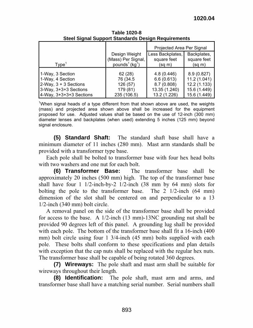
1020.04
893
Table 1020-8 Steel Signal Support Standards Design Requirements
Projected Area Per Signal
Type1
Design Weight (Mass) Per Signal,
pounds1 (kg1)
Less Backplates, square feet
(sq m)
Backplates, square feet
(sq m) 1-Way, 3 Section 1-Way, 4 Section 2-Way, 3 + 3 Sections 3-Way, 3+3+3 Sections 4-Way, 3+3+3+3 Sections
62 (28) 76 (34.5 126 (57) 179 (81)
235 (106.5)
4.8 (0.446) 6.6 (0.613) 8.7 (0.808)
13.35 (1.240) 13.2 (1.226)
8.9 (0.827)
11.2 (1.041) 12.2 (1.133) 15.6 (1.449) 15.6 (1.449)
1When signal heads of a type different from that shown above are used, the weights (mass) and projected area shown above shall be increased for the equipment proposed for use. Adjusted values shall be based on the use of 12-inch (300 mm) diameter lenses and backplates (when used) extending 5 inches (125 mm) beyond signal enclosure. (5) Standard Shaft: The standard shaft base shall have a minimum diameter of 11 inches (280 mm). Mast arm standards shall be provided with a transformer type base. Each pole shall be bolted to transformer base with four hex head bolts with two washers and one nut for each bolt. (6) Transformer Base: The transformer base shall be approximately 20 inches (500 mm) high. The top of the transformer base shall have four 1 1/2-inch-by-2 1/2-inch (38 mm by 64 mm) slots for bolting the pole to the transformer base. The 2 1/2-inch (64 mm) dimension of the slot shall be centered on and perpendicular to a 13 1/2-inch (340 mm) bolt circle. A removal panel on the side of the transformer base shall be provided for access to the base. A 1/2-inch (13 mm)-13NC grounding nut shall be provided 90 degrees left of this panel. A grounding lug shall be provided with each pole. The bottom of the transformer base shall fit a 16-inch (400 mm) bolt circle using four 1 3/4-inch (45 mm) bolts supplied with each pole. These bolts shall conform to these specifications and plan details with exception that the cap nuts shall be replaced with the regular hex nuts. The transformer base shall be capable of being rotated 360 degrees. (7) Wireways: The pole shaft and mast arm shall be suitable for wireways throughout their length. (8) Identification: The pole shaft, mast arm and arms, and transformer base shall have a matching serial number. Serial numbers shall
1020.04
894
be assigned by the Traffic Engineering and Services Administrator or shown on the plans. (d) Anchor Bolts for Steel Signal Support Poles and Standards: Anchor bolts shall be supplied in accordance with the standard details and shall be 1 3/4 inch (45 mm), 5 NC thread with a yield strength of 105,000 psi (724 MPa). and hot dipped galvanized for the top 12 inches (300 mm) and shall comply with ASTM A687-B7 or ASTM A193-B7. One additional anchor bolt shall be supplied by the contractor at no cost for acceptance testing by the department. (e) Loop Detector Sealants: Loop detector sealant shall be as specified in Sub 1020.02(c). (f) Timber Wood Poles: Poles shall comply with Section 1014.

895