Embed Size (px)
Citation preview
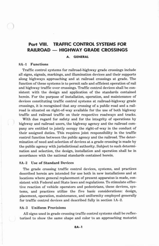
Part VIII. TRAFFIC CONTROL SYSTEMS FOR RAILROAD - HIGHWAY GRADE CROSSINGS
A. GENERAL
8A-1 Functions
Traffic control systems for railroad-highway grade crossings include all signs, signals, markings, and illumination devices and their supports along highways approaching and at railroad crossings a t grade. The function of these systems is to permit safe and efficient operation of rail and highway traffic over crossings. Traffic control devices shall be con- sistent with the design and application of the standards contained herein. For the purpose of installation, operation, and maintenance of devices constituting traffic control systems a t railroad-highway grade crossings, it is recognized that any crossing of a public road and a rail- road is situated on right-of-way available for the use of both highway traffic and railroad traffic on their respective roadways and tracks.
With due regard for safety and for the integrity of operations by highway and railroad users, the highway agency and the railroad com- pany are entitled to jointly occupy the right-of-way in the conduct of their assigned duties. This requires joint responsibility in the traffic control function between the public agency and the railroad. The deter- mination of need and selection of devices a t a grade crossing is made by the public agency with jurisdictional authority. Subject to such determi- nation and selection, the design, installation and operation shall be in accordance with the national standards contained herein.
8A-2 Use of Standard Devices
The grade crossing traffic control devices, systems, and practices described herein are intended for use both in new installations and at locations where general replacement of present apparatus is made, con- sistent with Federal and State laws and regulations. To stimulate effec- tive reaction of vehicle operators and pedestrians, these devices, sys- tems, and practices utilize the five basic considerations: design, placement, operation, maintenance, and uniformity employed generally for traffic control devices and described fully in section 1A-2.
8A-3 Uniform Provisions
All signs used in grade crossing traffic control systems shall be reflec- torized to show the same shape and color to an approaching motorist
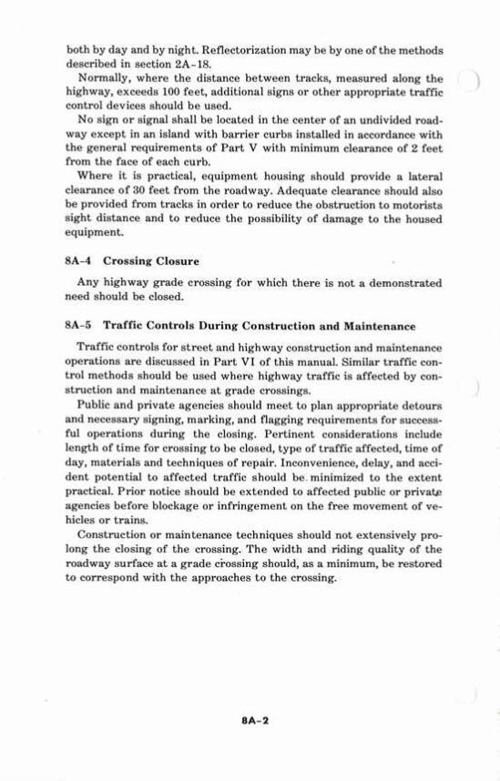
both by day and by night. Reflectorization may be by one of the methods described in section 2A-18.
Normally, where the distance between tracks, measured along the highway, exceeds 100 feet, additional signs or other appropriate traffic
1 control devices should be used.
No sign or signal shall be located in the center of an undivided road- way except in an island with barrier curbs installed in accordance with the general requirements of Part V with minimum clearance of 2 feet from the face of each curb.
Where it is practical, equipment housing should provide a lateral clearance of 30 feet from the roadway. Adequate clearance should also be provided from tracks in order to reduce the obstruction to motorists sight distance and to reduce the possibility of damage to the housed equipment.
8A-4 Crossing Closure
Any highway grade crossing for which there is not a demonstrated need should be closed.
8A-5 Traffic Controls During Construction and Maintenance
Traffic controls for street and highway construction and maintenance operations are discussed in Part VI of this manual. Similar traffic con- trol methods should be used where highway traffic is affected by con- struction and maintenance a t grade crossings. \
Public and private agencies should meet to plan appropriate detours and necessary signing, marking, and flagging requirements for success- ful operations during the closing. Pertinent considerations include length of time for crossing to be closed, type of traffic affected, time of day, materials and techniques of repair. Inconvenience, delay, and acci- dent potential to affected traffic should be. minimized to the extent practical. Prior notice should be extended to affected public or private agencies before blockage or infringement on the free movement of ve- hicles or trains.
Construction or maintenance techniques should not extensively pro- long the closing of the crossing. The width and riding quality of the roadway surface a t a grade ci-ossing should, as a minimum, be restored to correspond with the approaches to the crossing.
B. SIGNS AND MARKINGS
8B-1 Purpose
Passive traffic control systems, consisting of signs, pavement mark- ings, and grade crossing illumination, identify and direct attention to the location of a grade crossing, to permit vehicle operators and pedestrians to take appropriate action.
Where a railroad track has been abandoned or its use discontinued, all related traffic control devices shall be removed, and the tracks should be removed or covered.
8B-2 Railroad Crossing (Crossbuck) Sign (R15-1, 2)
The railroad crossing sign, commonly identified as the "crossbuck" sign, as a minimum shall be white reflectorized sheeting or equal, with the words RAILROAD CROSSING in black lettering. As a minimum, one crossbuck sign shall be used on each roadway approach to every grade crossing, alone o r in combination with other traffic control de- vices. If there are two or more tracks between the signs, the number of tracks shall be indicated on an auxiliary sign of inverted T shape mounted below the crossbuck in the manner and a t the heights indicated in figure 8-1 except that use of this auxiliary sign is optional a t cross- ings with automatic gates.
Where physically feasible and visible to approaching traffic the crossbuck sign shall be installed on the right hand side of the roadway on each approach to the crossing. Where an engineering study finds restricted sight distance or unfavorable road geometry, crossbuck signs shall be placed back to back or otherwise located so that two faces are
*out displayed to& approach. Crossbuck signs should be located with respect to the roadway pave-
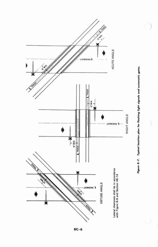
ment or shoulder in accordance with the criteria in sections 2A-21 through 2A-27 and figures 2-1 and 2-2 (pages 2A-9 and 2A-10) and should be located with respect to the nearest track in accordance with signal locations in figure 8-7, (page 8C-6). The normal lateral clearances (sec. 2A-24), 6 feet from the edge of the highway shoulder or 12 feet from the edge of the traveled way in rural areas and 2 feet from the face of the curb in urban areas will usually be attainable. Where unusual conditions demand, variations determined by good judgment should pro- vide the best possible combination of view and safety clearances attain- able, occasionally utilizing a location on the left-hand side of the road- way.
Appropriate details of R15-1 and R15-2 are available inYkStandard Highway Signs Tb&&.*
* Available from *D.C. G P O , P+ ;;
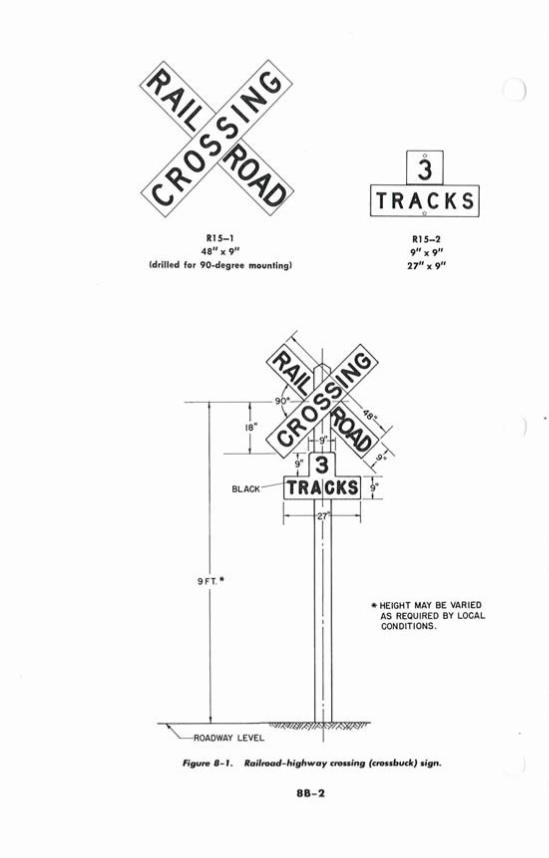
R15-1 48" x 9"
(drilled for 90-degree mounting1
\
ROADWAY LEVEL
*HEIGHT MAY BE VARIED AS REQUIRED BY LOCAL CONDITIONS.
Figure 8-1. Railmad-highway cnruing (crossbuck) sign.
88-2
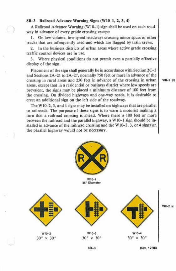
8B-3 Railroad Advance Warning Signs (W10-1, 2, 3, 4) A Railroad Advance Warning (W10-1) sign shall be used on each road-
way in advance of every grade crossing except: 1. On low-volume, low-speed roadways crossing minor spurs or other
tracks that are infrequently used and which are flagged by train crews. 2. In the business districts of urban areas where active grade crossing
traffic control devices are in use. 3. Where physical conditions do not permit even a partially effective
display of the sign.
Placement of the sign shall generally be in accordance with Section 2C-3 and Sections 2A-21 to 2A-27, normally 750 feet or more in advance of the crossing in rural areas and 250 feet in advance of the crossing in urban areas, except that in a residential or business district where low speeds are prevalent, the signs may be placed a minimum distance of 100 feet from the crossing. On divided highways and one-way roads, it is desirable to erect an additional sign on the left side of the roadway.
The W10-2,3, and 4 signs may be installed on highways that are parallel to railroads. The purpose of these signs is to warn a motorist making a turn that a railroad crossing is ahead. Where there is 100 feet or more between the railroad and the parallel highway, a W10-1 sign should be in- stalled in advance of the railroad crossing and the W10-2, 3, or 4 signs on the parallel highway would not be necessary.
WIO-1 36" Diameter
Rev. 12183
.sl!elap sloqwhs X
U 104 sG
u!y~ew pue
s* A
sMq
fi!~ 104 la
qe
qd
lv ple
pu
els 0
1 lahaa
'auel qoeoldde qoea u! pasn aq
plnoqs sloqwhs !jX
a
lenp!n!pu! pue 'sauel qoeoldde Ile noJoe pu
alxa
plnoqs spueq aslansuen a
ql speol a
ue
l-!llnu
uo
'~U
!SS
OJ
~
e 01 qaeoldde a
ql uo uo!lelado qoeoldde a
ue
l-oM
llo4
au!llaluaa e q
l!
~
pa
yle
u a
q plnoqs A
eMpeol a
ue
l-aa
lql v
'iaa4 09 ue
ql ssal IO
U
aq
plnoqs A
lqe
qo
ld znq 'fiu
!qo
w~
dd
e o!lle
ll lelno!qan a
ql 40 aauels!p 1q6!s a
ql pue paads qoeoldde
aq
l 01 6u!p~
oooe Alen II!M yo
ell lsaleau a
ql
01
Bu!ylew
Bu!sso~o peoll!ei a
ql w
all aouels!p a
ql.
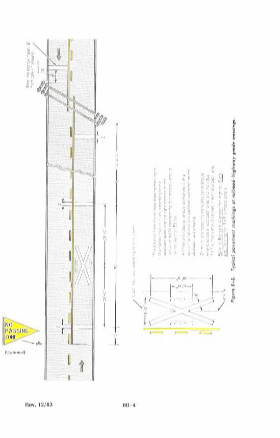
8B-4 Pavement Markings
1 Pavement markings in advance of a grade crossing shall consist of an X, the letters RR, a no passing marking (2-lane roads), and certain transverse lines. Identical markings shall be placed in each approach lane on all paved approaches to grade crossings where grade crossing signals or automatic gates are located, and at all other grade crossings where the prevailing speed of highway traffic is 40 mph or greater.
The markings shall also be placed at crossings where the engineering studies indicate there is a significant potential conflict between vehicles and trains. At minor crossings or in urban areas, these markings may be omitted if engineering study indicates that other devices installed provide suitable control.
The design of railroad crossing pavement markings shall be essentially as illustrated in figure 8-2. The symbols and letters are elongated to allow for the low angle at which they are viewed. All markings shall be reflectorized white except for the no-passing markings which shall be reflectorized yellow.
8B-5 Illumination at Grade Crossings
At grade crossings where a substantial amount of railroad operation is conducted at night, particularly where train speeds are low, where cross- ings are blocked for long periods, or accident history indicates that motorists experience difficulty in seeing trains or control devices during the hours of darkness, illumination at and adjacent to the crossing may be installed to supplement other traffic control devices where an engineering analysis determines that better visibility of the train is needed. Regardless of the presence of other control devices, illumination will aid the motorist in observing the presence of railroad cars on a crossing where the gradient of the vehicular approaches is such that the headlights of an oncoming vehicle shine under or over the cars.
Recommended types and location of luminaires for grade crossing illumination are contained in the American National Standard Practice for Roadway Lighting, RP8.* In any event, luminaires shall be so located and light therefrom so directed as to not interfere with aspects of the railroad signal system and not interfere with the field of view of members of the
I locomotive crew.
8B-6 Exempt Crossing Signs (R15-3, W10-la) When authorized by law or regulation a supplemental sign (R15-3)
bearing the word EXEMPT may be used below the Crossbuck and Track signs at the crossing, and supplemental sign (W10-la) may be used below the Railroad Advance Warning sign. These supplemental signs are to in-
* Available from the Illuminating Engineering Society, New York, N.Y. 10017. -
88-5 Rev. 12/83
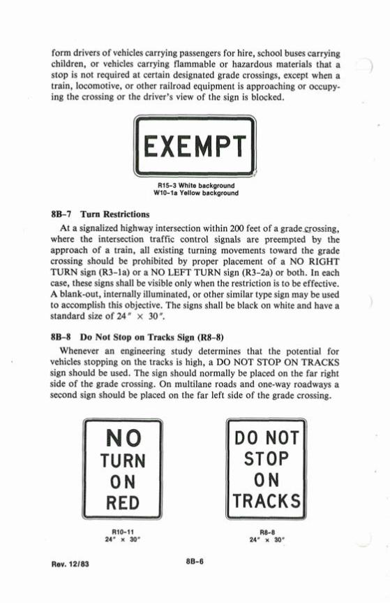
form drivers of vehicles carrying passengers for hire, school buses carrying children, or vehicles carrying flammable or hazardous materials that a stop is not required at certain designated grade crossings, except when a train, locomotive, or other railroad equipment is approaching or occupy- ing the crossing or the driver's view of the sign is blocked.
Rl5-3 White background W10-la Yellow background
8B-7 Turn Restrictions At a signalized highway intersection within 200 feet of a gradeaossing,
where the intersection traffic control signals are preempted by the approach of a train, all existing turning movements toward the grade crossing should be prohibited by proper placement of a NO RIGHT TURN sign (R3-la) or a NO LEFT TURN sign (R3-2a) or both. In each case, these signs shall be visible only when the restriction is to be effective. A blank-out, internally illuminated, or other similar type sign may be used to accomplish this objective. The signs shall be black on white and have a standard size of 24 " x 30 ". 8B-8 Do Not Stop on Tracks Sign (R8-8)
Whenever an engineering study determines that the potential for vehicles stopping on the tracks is high, a DO NOT STOP ON TRACKS sign should be used. The sign should normally be placed on the far right side of the grade crossing. On multilane roads and one-way roadways a second sign should be placed on the far left side of the grade crossing.
TRACKS B Rev. 12/83
8B-9 STOP Signs at Grade Crossings (Rl-1, W3-1) 'l
1 The use of the STOP signs at railroad-highway grade crossings shall be limited to those grade crossings selected after need is established by a detailed traffic engineering study. Such crossings should have the follow- ing characteristics:
1. Highway should be secondary in character with low traffic counts.
2. Train traffic should be substantial. 3. Line of sight to an approaching train is restricted by physical
features such that approaching traffic is required to reduce speed to 10 miles per hour or less in order to stop safely.
4. At the stop bar, there must be sufficient sight distance down the track to afford ample time for a vehicle to cross the track before the arrival of the train.
The engineering study may determine other compelling reasons for the need to install a STOP sign, however, this should only be an interim measure until active traffic control signals can be installed. STOP signs shall not be used on primary through highways or at grade crossings with active traffic control devices.
Whenever a STOP sign is installed at a grade ciossing, a Stop Ahead sign shall be installed in advance of the STOP sign.
Val-5 (c)
Rev. 12/83

C, SIGNALS AND GATES
8C-1 Purpose and Meaning
Active traffic control systems inform motorists and pedestrians of the approach or presence of trains, locomotives, or railroad cars on grade crossings. The meaning of flashing light signals and gates shall be as defined in the Uniform Vehicle Code (sees. 11-701 & 11-703, Revised 1968).*
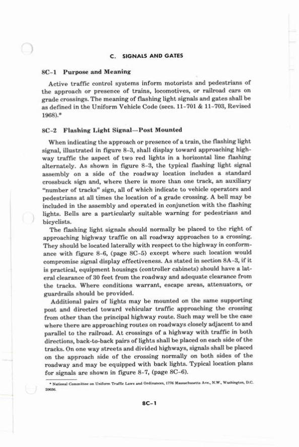
8C-2 Flashing Light Signal-Post Mounted
When indicating the approach or presence of a train, the flashing light signal, illustrated in figure 8-3, shall display toward approaching high- way traffic the aspect of two red lights in a horizontal line flashing alternately. As shown in figure 8-3, the typical flashing light signal assembly on a side of the roadway location includes a standard crossbuck sign and, where there is more than one track, an auxiliary "number of tracks" sign, all of which indicate to vehicle operators and pedestrians at all times the location of a grade crossing. A bell may be included in the assembly and operated in conjunction with the flashing lights. Bells are a particularly suitable warning for pedestrians and bicyclists.
The flashing light signals should normally be placed to the right of approaching highway traffic on all roadway approaches to a crossing. They should be located laterally with respect to the highway in conform- ance with figure 8-6, (page 8C-5) except where such location would compromise signal display effectiveness. As stated in section 8A-3, if it is practical, equipment housings (controller cabinets) should have a lat- eral clearance of 30 feet from the roadway and adequate clearance from the tracks. Where conditions warrant, escape areas, attenuators, or guardrails should be provided.
Additional pairs of lights may be mounted on the same supporting post and directed toward vehicular traffic approaching the crossing from other than the principal highway route. Such may well be the case where there are approaching routes on roadways closely adjacent to and parallel to the railroad. At crossings of a highway with traffic in both directions, back-to-back pairs of lights shall be placed on each side of the tracks. On one way streets and divided highways, signals shall be placed on the approach side of the crossing normally on both sides of the roadway and may be equipped with back lights. Typical location plans for signals are shown in figure 8-7, (page 8C-6).
National Committee on Uniform Traffc Laws and Ordinances, 1776 Massachusetts Ave, N.W. W a s h i n g a ~ D.C. 20036.
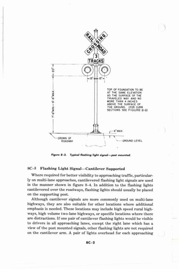
TOP OF FOUNDATION TO BE AT THE SAME ELEVATION AS THE SURFACE OF THE TRAVELED WAY AND NO MORE THAN 4 INCHES ABOVE THE SURFACE OF THE GROUND. (FOR CURB SECTIONS SEE FIGURE 8-61
\ 1 '. ROAOWAY \ -GROUND
Figure 8-3. Typical flashing light signal-port mounted.
8C-3 Flashing Light Signal-Cantilever Supported
LEVEL
Where required for better visibility to approaching traffic, particular- ly on multi-lane approaches, cantilevered flashing light signals are used in the manner shown in figure 8-4. In addition to the flashing lights cantilevered over the roadways, flashing lights should usually be placed on the supporting post.
Although cantilever signals are more commonly used on multi-lane highways, they are also suitable for other locations where additional emphasis is needed. These locations may include high speed rural high- ways, high volume two-lane highways, or specific locations where there are distractions. If one pair of cantilever flashing lights would be visible to drivers in all approaching lanes, except the right lane which has a view of the post mounted signals, other flashing lights are not required on the cantilever arm. A pair of lights overhead for each approaching
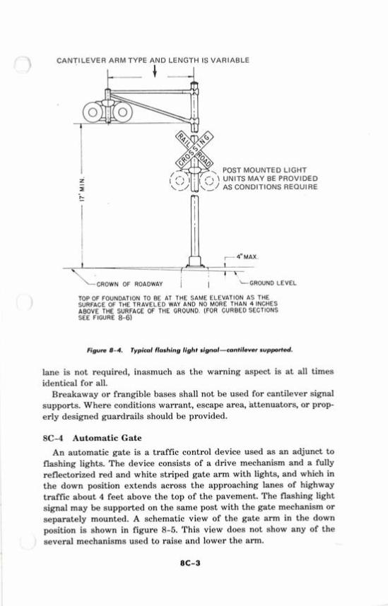
CANTILEVER ARM TYPE AND LENGTH IS VARIABLE
POST MOUNTED LIGHT \ UNITS MAY BE PROVIDED
AS CONDITIONS REQUIRE =l-
i 1 4" MAX
I 1 \ \CROWN OF ROADWAY i I LGROUND LEVEL
TOP OF FOUNDATION TO BE AT THE SAME ELEVATION A S THE SURFACE OF THE TRAVELED WAY A N D NO MORE T H A N 4 INCHES ABOVE THE SURFACE OF THE GROUND. (FOR CURBED SECTIONS SEE FIGURE 8-6)
Figure 8-4. Typical flashing light signal-cantilever supported.
lane is not required, inasmuch as the warning aspect is a t all times identical for all.
Breakaway or frangible bases shall not be used for cantilever signal supports. Where conditions warrant, escape area, attenuators, or prop- erly designed guardrails should be provided.
8C-4 Automatic Gate
An automatic gate is a traffic control device used as an adjunct to flashing lights. The device consists of a drive mechanism and a fully reflectorized red and white striped gate arm with lights, and which in the down position extends across the approaching lanes of highway traffic about 4 feet above the top of the pavement. The flashing light signal may be supported on the same post with the gate mechanism or separately mounted. A schematic view of the gate arm in the down position is shown in figure 8-5. This view does not show any of the several mechanisms used to raise and lower the arm.
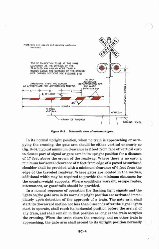
NOTE: Gate arm supports and op-ralinp mechanism - not shown
TOP OF FOUNDATION TO BE AT THE SAME ELEVATION AS THE SURFACE OF THE TRAVELED WAY AND NO MORE THAN 4 INCHES ABOVE THE SURFACE OF THE GROUND (FOR CURBED SECTIONS SEE F I G U R E 8-6)
16 INCH
DiMENSlONS A-B-C AND LENGTH ALTERNATE
REFLECTORIZED RED , AS APPROPRIATE FOR APPROACHING TRAFFIC AND WHITE
BOTH SIDES i
-. : 7- YL OF ROADWAY I i I \ GROUND LEVEL , Figure 8-5. Schematic view of automatic -re.
In its normal upright position, when no train is approaching or occu- pying the crossing, the gate arm should be either vertical or nearly so (fig. 8-6). Typical minimum clearance is 2 feet from face of vertical curb to closest part of signal or gate arm in its upright position for a distance of 17 feet above the crown of the roadway. Where there is no curb, a I
minimum horizontal clearance of 2 feet from edge of a paved or surfaced shoulder shall be provided with a minimum clearance of 6 feet from the edge of the traveled roadway. Where gates are located in the median, 1 additional width may be required to provide the minimum clearance for I
the counterweight supports. Where conditions warrant, escape routes, attenuators, or guardrails should be provided.
In a normal sequence of operation the flashing light signals and the I
lights o the gate arm in its normal upright position are activated imme- diately \ upo detection of the approach of a train. The gate arm shall start its downward motion not less than 3 seconds after the signal lights
i I
start to operate, shall reach its horizontal position before the arrival of any train, and shall remain in that position as long as the train occupies the crossing. When the train clears the crossing, and no other train is approaching, the gate arm shall ascend to its upright position normally -
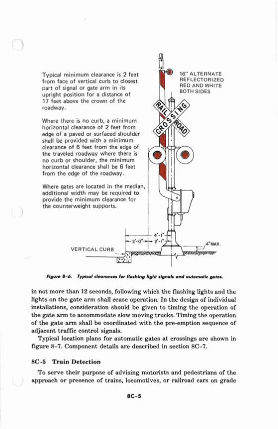
Typical minimum clearance is 2 feet 16" ALTERNATE
from face of vertical curb to closest REFLECTORIZED
part of signal or gate arm in its RED AND WHITE
upright position for a distance of 17 feet above the crown of the roadway.
Where there is no curb, a minimum horizontal clearance of 2 feet from edge of a paved or surfaced shoulder shall be provided with a minimum clearance of 6 feet from the edge of the traveled roadway where there is no curb or shoulder, the minimum horizontal clearance shall be 6 feet from the edge of the roadway.
Where gates are located in the median, additional width may be required to provide the minimum clearance for the counterweight supports.
X VERTICAL CURB
Figurn 8-6. Typic01 cleamnces for flashing light signals and automatic gates.
in not more than 12 seconds, following which the flashing lights and the lights on the gate arm shall cease operation. In the design of individual installations, consideration should be given to timing the operation of the gate arm to accommodate slow moving trucks. Timing the operation of the gate arm shall be coordinated with the pre-emption sequence of adjacent traffic control signals.
Typical location plans for automatic gates a t crossings are shown in figure 8-7. Component details are described in section 8C-7.
8C-5 Train Detection
To serve their purpose of advising motorists and pedestrians of the approach o r presence of trains, locomotives, or railroad cars on grade
crossings, the devices employed in active traffic control systems shall be actuated by some form of train detection. Generally the method is auto-
] matic, requiring no personnel to operate it, although a small number of such installations are still operated under manual control. The automatic method currently uses the railroad circuit.*
Railroad circuits insofar as practical shall be designed on the fail safe principle, which uses closed circuits.
On tracks where trains operate a t speeds of 20 mph or higher, circuits controlling automatic flashing light signals shall provide for a minimum operation of 20 seconds before arrival of any train on such track. On other tracks used for switching and assembling trains a means shall be provided to warn approaching highway traffic. For automatic gate op- eration, circuits shall provide for the operating sequence described in section 8C-4.
Where the speeds of different trains on a given track vary consider- ably under normal operation, special devices or circuits should be in- stalled to provide reasonably uniform notice in advance of all train movements over the crossing. Special control features should be used to eliminate the effects of station stops and switching operations within approach control circuits.
8C-6 Traffic Signals at or Near Grade Crossings (fig. 8-8)
When highway intersection traffic control signals are within 200 feet of a grade crossing, control of the traffic flow should be designed to provide the vehicle operators using the crossing a measure of safety a t least equal to that which existed prior to the installation of such signals. Accordingly, design, installation, and operation should be based upon a total systems approach in order that all relevant features may be con- sidered.
When the grade crossing is equipped with an active traffic control system, the normal sequence of highway intersection signal indications should be preempted upon approach of trains to avoid entrapment of vehicles on the crossing by conflicting aspects of the highway traffic signals and the grade crossings signals. This preemption feature re- quires an electrical circuit between the control relay of the grade cross- ing signals and the controller assembly in order to establish and main- tain the preempted condition during the time that the grade crossing signals are in operation. Where multiple or successive preemption may occur from differing modes, train actuation should receive first priority and emergency vehicles second priority.
Where a signalized highway intersection is adjacent to a grade cross- ing not provided with an active traffic control system, the possibility of vehicles being trapped on the crossing remains and preemption of the
'Definition: "Railroad Circuit-A eontml circuit whieh includes all train movement detection and logic components whieh are physically andlor electrically integrated ~ , i t h track structures or associated manual control."
signal controller is usually required. However, a t some locations, the characteristics of the crossing and intersection area along with favor- able speeds of both vehicular and train traffic may permit alternate ) methods of warning traffic. Where preemption of the traffic signal con- trol is determined to be desirable, consideration should be given to the installation of active traffic control devices a t the grade crossing, inas- much as the cost of the grade crossing devices would usually represent a minor addition to the cost of the railroad circuits required for the preemption function.
Except under unusual circumstances, preemption should be limited to the highway intersection traffic signals within 200 feet of the grade crossing.
The preemption sequence initiated when the train first enters the approach circuit, shall a t once bring into effect a highway signal display which will permit traffic to clear the tracks before the train reaches the crossing. The preemption shall not cause any short vehicular clearances and all necessary vehicular clearances shall be provided. However, be- cause of the relative hazards involved, pedestrian clearances may be I
abbreviated in order to provide the track clearance display as early as I
possible. I I
To avoid misinterpretation during the time the clear-out signals are i
green, consideration should be given to the use of 12-inch red lenses in the signals which govern highway traffic movement over the crossing with adequately screened or louvered green lenses in the clear-out sig- I
nals beyond the crossing. After the track clearance phase, the highway intersection traffic con-
trol signals should be operated to permit vehicle movements that do not cross the tracks, but shall not provide a through circular green or arrow indication for movements over the tracks. This does not prohibit green indications for highway traffic movements on a roadway paralleling the tracks.
Where feasible, traffic control signals near grade crossings should be operated so that vehicles are not required to stop on the tracks even though in some cases this will increase the waiting time. The exact nature of the display and the location of the signals to accomplish this will depend on the physical relationship of the tracks to the intersection area.
Highway traffic control signals shall not be used on mainline railroad crossings in lieu of flashing light signals. However, a t industrial track crossings and other places where train movements are very slow (as in switching operations), highway traffic control signals may be used in lieu of conventional flashing light signals to warn vehicle operators of the approach or presence of a train. The provisions of this part relating to traffic signal design, installation, and operation are applicable as ap- propriate where highway traffic signals are so used.
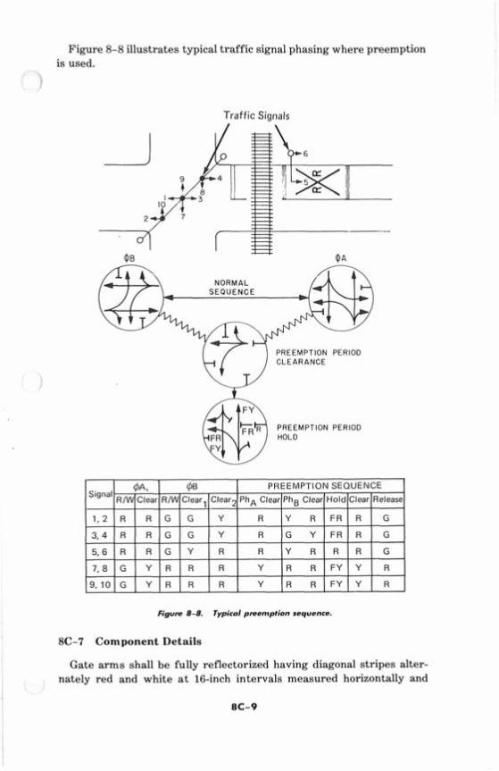
Figure 8-8 illustrates typical traffic signal phasing where preemption is used.
Traffic Signals
SEQUENCE
PREEMPTION PERIOD CLEARANCE
(ffl3 E:IMPTION PERIOD
Figure 8-8. Typical preemption sequence.
8C-7 Component Details
Gate arms shall be fully reflectorized having diagonal stripes alter- nately red and white a t 16-inch intervals measured horizontally and
shall have a t least three red lights as indicated in figure 8-5 (page 82-41.
When activated, the gate arm light nearest the tip shall be illuminated continuously and the other two lights shall flash alternately in unison
j with the flashing light signals.
Flashing light units shall flash alternately. The number of flashes per minute for each incandescent lamp shall be 35 minimum and 55 maxi- mum. Each lamp shall be illuminated approximately the same length of time. Total time of illumination of each pair of incandescent lamps shall be practically the entire operating time.
Where local conditions will permit, a lateral escape route to the right of the highway in advance of the grade crossing traffic control device should be kept free of guardrail or other ground obstruction. Where guardrail is not deemed necessary nor appropriate, rigid non-yielding type barriers are not to be used for protecting signal supports. In indus- trial or other areas involving only low-speed highway traffic and where signals are vulnerable to damage by turning truck traffic, ring type guardrail may be installed to provide protection for the signal assembly.
The same lateral clearances and roadside safety features should apply to flashing light signal and automatic gate locations on both the right and left sides of the roadway.
Two sizes of lenses, 8-inch diameter and 12-inch diameter, are avail- able for flashing light signal units. The larger lens provides somewhat better visibility. In choosing between the two sizes of lenses, consider- ation should be given to the principles stated in section 4B-8 for choos- )
ing between the &inch and 12-inch lenses for use in highway intersec- tion traffic control signals.
The requirement for storage battery source of standard power for signal and gate operation during outages in the primary power source limits the operating voltage to 10 and the maximum lamp wattage is generally 25.
Many other details of grade crossing traffic control systems which are not set forth herein are contained in references in 1A-7.
D. SYSTEMS AND DEVICES
8D-1 Selection of Systems and Devices
The selection of traffic control devices a t a grade crossing is deter- mined by public agencies having jurisdictional responsibility at specific locations.
Active grade crossing traffic control systems range from
1. post mounted flashing light signals to 2. automatic gates combined with
(a) post mounted flashing light signals, (b) cantilever flashing light signals, or (c) combination of the above
Any of the foregoing may or may not incorporate a bell.
Due to the large number of significant variables which must be con- sidered there is no single standard system of active traffic control de- vices universally applicable for grade crossings. Based on an engineer- ing and traffic investigation, a determination is made whether any active traffic control system is required a t a crossing and, if so, what type is appropriate. Before a new or modified grade crossing traffic control system is installed, approval is required from the appropriate agency within a given State.