Embed Size (px)
Citation preview

Part VI — Fuel Gas CHAPTER 24
FUEL GAS The text of this chapter is excerpted from the 2003 edition of the International Fuel Gas Code and has been modified where necessary to make such text conform to the scope of application of the International Residential Code for One- and Two-Family Dwellings. The section numbers appearing in parentheses after each section number represent the location of the corresponding text in the International Fuel Gas Code.
SECTION G2401 (101) GENERAL
G2401.1 (101.2) Application. This chapter covers those fuel-gas piping systems, fuel-gas utilization equipment and related accessories, venting systems and combustion air configurations most commonly encountered in the construction of one- and two-family dwellings and structures regulated by this code.
Exceptions:
1. As an alternative to the provisions of this code, fuel-gas piping systems, fuel-gas utilization equipment and related accessories in existing buildings that are undergoing repairs, alterations, changes in occupancy or construction of additions shall be permitted to comply with the provisions of the International Existing Building Code.
[W] 2. The standards for liquefied petroleum gas installations shall be NFPA 58 (Liquefied Petroleum Gas Code) and ANSI Z223.1/NFPA 54 (National Fuel Gas Code).
Coverage of piping systems shall extend from the point of delivery to the outlet of the equipment shutoff valves (see “Point of delivery”). Piping systems requirements shall include design, materials, components, fabrication, assembly, installation, testing, inspection, operation and maintenance. Requirements for gas utilization equipment and related accessories shall include installation, combustion and ventilation air and venting and connections to piping systems.
The omission from this chapter of any material or method of installation provided for in the International Fuel Gas Code shall not be construed as prohibiting the use of such material or method of installation. Fuel-gas piping systems, fuel-gas utilization equipment and related accessories, venting systems and combustion air configurations not specifically covered in these chapters shall comply with the applicable provisions of the International Fuel Gas Code.
Gaseous hydrogen systems shall be regulated by Chapter 7 of the International Fuel Gas Code.
This chapter shall not apply to the following:
1. Liquified natural gas (LNG) installations.
2. Temporary LP-gas piping for buildings under construction or renovation that is not to become part of the permanent piping system.
3. Except as provided in Section G2412.1.1, gas piping, meters, gas pressure regulators, and other appurtenances used by the serving gas supplier in the distribution of gas, other than undiluted LP-gas.
4. Portable LP-gas equipment of all types that is not connected to a fixed fuel piping system.
5. Portable fuel cell appliances that are neither connected to a fixed piping system nor interconnected to a power grid.
6. Installation of hydrogen gas, LP-gas and compressed natural gas (CNG) systems on vehicles.
SECTION G2402 (201) GENERAL
G2402.1 (201.1) Scope. Unless otherwise expressly stated, the following words and terms shall, for the purposes of this chapter, have the meanings indicated in this chapter.
G2402.2 (201.2) Interchangeability. Words used in the present tense include the future; words in the masculine gender include the feminine and neuter; the singular number includes the plural and the plural, the singular.
G2402.3 (201.3) Terms defined in other codes. Where terms are not defined in this code and are defined in the ICC Electrical Code, International Building Code, International Fire Code, International Mechanical Code or International Plumbing Code, such terms shall have meanings ascribed to them as in those codes.
SECTION G2403 (202) GENERAL DEFINITIONS
AIR CONDITIONING, GAS FIRED. A gas-burning, automatically operated appliance for supplying cooled and/or dehumidified air or chilled liquid.
AIR, EXHAUST. Air being removed from any space or piece of equipment and conveyed directly to the atmosphere by means of openings or ducts.
AIR-HANDLING UNIT. A blower or fan used for the purpose of distributing supply air to a room, space or area.
AIR, MAKEUP. Air that is provided to replace air being exhausted.
ALTERATION. A change in a system that involves an extension, addition or change to the arrangement, type or purpose of the original installation.
2003 SEATTLE RESIDENTIAL CODE 331

ANODELESS RISER. A transition assembly in which plasticpiping is installed and terminated above ground outside of abuilding.
APPLIANCE (EQUIPMENT). Any apparatus or equipmentthat utilizes gas as a fuel or raw material to produce light, heat,power, refrigeration or air conditioning.
APPLIANCE, FAN-ASSISTED COMBUSTION. An appli-ance equipped with an integral mechanical means to eitherdraw or force products of combustion through the combustionchamber or heat exchanger.
APPLIANCE, AUTOMATICALLY CONTROLLED. Ap-pliances equipped with an automatic burner ignition and safetyshut-off device and other automatic devices, which accomplishcomplete turn-on and shut-off of the gas to the main burner orburners, and graduate the gas supply to the burner or burners,but do not affect complete shut-off of the gas.
APPLIANCE, UNVENTED. An appliance designed or in-stalled in such a manner that the products of combustion are notconveyed by a vent or chimney directly to the outside atmo-sphere.
APPLIANCE, VENTED. An appliance designed and in-stalled in such a manner that all of the products of combustionare conveyed directly from the appliance to the outside atmo-sphere through an approved chimney or vent system.
ATMOSPHERIC PRESSURE. The pressure of the weight ofair and water vapor on the surface of the earth, approximately14.7 pounds per square inch (psia) (101 kPa absolute) at sealevel.
AUTOMATIC IGNITION. Ignition of gas at the burner(s)when the gas controlling device is turned on, includingreignition if the flames on the burner(s) have been extinguishedby means other than by the closing of the gas controlling de-vice.
BAROMETRIC DRAFT REGULATOR. A balanceddamper device attached to a chimney, vent connector, breech-ing or flue gas manifold to protect combustion equipment bycontrolling chimney draft. A double-acting barometric draftregulator is one whose balancing damper is free to move in ei-ther direction to protect combustion equipment from both ex-cessive draft and backdraft.
BOILER, LOW-PRESSURE. A self-contained gas-fired ap-pliance for supplying steam or hot water.
Hot water heating boiler. A boiler in which no steam isgenerated, from which hot water is circulated for heatingpurposes and then returned to the boiler, and that operates atwater pressures not exceeding 160 psig (1100 kPa gauge)and at water temperatures not exceeding 250°F (121°C) ator near the boiler outlet.
Hot water supply boiler. A boiler, completely filled withwater, which furnishes hot water to be used externally to it-self, and that operates at water pressures not exceeding 160psig (1100 kPa gauge) and at water temperatures not ex-ceeding 250°F (121°C) at or near the boiler outlet.
Steam heating boiler. A boiler in which steam is generatedand that operates at a steam pressure not exceeding 15 psig(100 kPa gauge).
BRAZING. A metal joining process wherein coalescence isproduced by the use of a nonferrous filler metal having a melt-ing point above 1,000°F (538°C), but lower than that of the basemetal being joined. The filler material is distributed betweenthe closely fitted surfaces of the joint by capillary action.
BTU. Abbreviation for British thermal unit, which is the quan-tity of heat required to raise the temperature of 1 pound (454 g)of water 1°F (0.56°C) (1 Btu = 1055 J).
BURNER. A device for the final conveyance of the gas, or amixture of gas and air, to the combustion zone.
Induced-draft. A burner that depends on draft induced by afan that is an integral part of the appliance and is locateddownstream from the burner.
Power. A burner in which gas, air or both are supplied atpressures exceeding, for gas, the line pressure, and for air,atmospheric pressure, with this added pressure being ap-plied at the burner.
CHIMNEY. A primarily vertical structure containing one ormore flues, for the purpose of carrying gaseous products ofcombustion and air from an appliance to the outside atmo-sphere.
Factory-built chimney. A listed and labeled chimney com-posed of factory-made components, assembled in the fieldin accordance with manufacturer’s instructions and the con-ditions of the listing.
Masonry chimney. A field-constructed chimney composedof solid masonry units, bricks, stones or concrete.
CLEARANCE. The minimum distance through air measuredbetween the heat-producing surface of the mechanical appli-ance, device or equipment and the surface of the combustiblematerial or assembly.
CLOTHES DRYER. An appliance used to dry wet laundry bymeans of heated air.
Type 1. Factory-built package, multiple production. Pri-marily used in the family living environment. Usually thesmallest unit physically and in function output.
CODE. These regulations, subsequent amendments thereto, orany emergency rule or regulation that the administrative au-thority having jurisdiction has lawfully adopted.
CODE OFFICIAL. The officer or other designated authoritycharged with the administration and enforcement of this code,or a duly authorized representative.
COMBUSTION. In the context of this code, refers to the rapidoxidation of fuel accompanied by the production of heat or heatand light.
COMBUSTION AIR. Air necessary for complete combustionof a fuel, including theoretical air and excess air.
COMBUSTION CHAMBER. The portion of an appliancewithin which combustion occurs.
COMBUSTION PRODUCTS. Constituents resulting fromthe combustion of a fuel with the oxygen of the air, includingthe inert gases, but excluding excess air.
CONCEALED LOCATION. A location that cannot be ac-cessed without damaging permanent parts of the building
332 2003 INTERNATIONAL RESIDENTIAL CODE®
FUEL GAS
structure or finish surface. Spaces above, below or behindreadily removable panels or doors shall not be considered asconcealed.
CONCEALED PIPING. Piping that is located in a concealedlocation (see “Concealed location”).
CONDENSATE. The liquid that condenses from a gas (in-cluding flue gas) caused by a reduction in temperature or in-crease in pressure.
CONNECTOR. The pipe that connects an approved applianceto a chimney, flue or vent.
CONTROL. A manual or automatic device designed to regu-late the gas, air, water or electrical supply to, or operation of, amechanical system.
CONVERSION BURNER. A unit consisting of a burner andits controls for installation in an appliance originally utilizinganother fuel.
CUBIC FOOT. The amount of gas that occupies 1 cubic foot(0.02832 m3) when at a temperature of 60°F (16°C), saturatedwith water vapor and under a pressure equivalent to that of 30inches of mercury (101 kPa).
DAMPER. A manually or automatically controlled device toregulate draft or the rate of flow of air or combustion gases.
DECORATIVE GAS APPLIANCE, VENTED. A ventedappliance wherein the primary function lies in the aesthetic ef-fect of the flames.
DECORATIVE GAS APPLIANCES FOR INSTALLA-TION IN VENTED FIREPLACES. A vented appliance de-signed for installation within the fire chamber of a ventedfireplace, wherein the primary function lies in the aesthetic ef-fect of the flames.
DEMAND. The maximum amount of gas input required perunit of time, usually expressed in cubic feet per hour, or Btu/h(1 Btu/h = 0.2931 W).
DESIGN FLOOD ELEVATION. The elevation of the “de-sign flood,” including wave height, relative to the datum speci-fied on the community’s legally designated flood hazard map.
DILUTION AIR. Air that is introduced into a draft hood and ismixed with the flue gases.
DIRECT-VENT APPLIANCES. Appliances that are con-structed and installed so that all air for combustion is deriveddirectly from the outside atmosphere and all flue gases are dis-charged directly to the outside atmosphere.
DRAFT. The pressure difference existing between the equip-ment or any component part and the atmosphere, that causes acontinuous flow of air and products of combustion through thegas passages of the appliance to the atmosphere.
Mechanical or induced draft. The pressure difference cre-ated by the action of a fan, blower or ejector that is locatedbetween the appliance and the chimney or vent termination.
Natural draft. The pressure difference created by a vent orchimney because of its height, and the temperature differ-ence between the flue gases and the atmosphere.
DRAFT HOOD. A nonadjustable device built into an appli-ance, or made as part of the vent connector from an appliance,
that is designed to (1) provide for ready escape of the flue gasesfrom the appliance in the event of no draft, backdraft, or stop-page beyond the draft hood, (2) prevent a backdraft from enter-ing the appliance, and (3) neutralize the effect of stack action ofthe chimney or gas vent upon operation of the appliance.
DRAFT REGULATOR. A device that functions to maintain adesired draft in the appliance by automatically reducing thedraft to the desired value.
DRIP. The container placed at a low point in a system of piping tocollect condensate and from which the condensate is removable.
DUCT FURNACE. A warm-air furnace normally installed inan air-distribution duct to supply warm air for heating. Thisdefinition shall apply only to a warm-air heating appliance thatdepends for air circulation on a blower not furnished as part ofthe furnace.
EQUIPMENT. See “Appliance.”
FIREPLACE. A fire chamber and hearth constructed of non-combustible material for use with solid fuels and provided witha chimney.
Masonry fireplace. A hearth and fire chamber of solid ma-sonry units such as bricks, stones, listed masonry units or re-inforced concrete, provided with a suitable chimney.
Factory-built fireplace. A fireplace composed of listedfactory-built components assembled in accordance with theterms of listing to form the completed fireplace.
FLAME SAFEGUARD. A device that will automatically shutoff the fuel supply to a main burner or group of burners whenthe means of ignition of such burners becomes inoperative, andwhen flame failure occurs on the burner or group of burners.
FLOOD HAZARD AREA. The greater of the following twoareas:
1. The area within a floodplain subject to a 1 percent orgreater chance of flooding in any given year.
2. This area designated as a flood hazard area on a commu-nity’s flood hazard map, or otherwise legally designated.
FLOOR FURNACE. A completely self-contained furnacesuspended from the floor of the space being heated, taking airfor combustion from outside such space and with means for ob-serving flames and lighting the appliance from such space.
FLUE, APPLIANCE. The passage(s) within an appliancethrough which combustion products pass from the combustionchamber of the appliance to the draft hood inlet opening on anappliance equipped with a draft hood or to the outlet of the ap-pliance on an appliance not equipped with a draft hood.
FLUE COLLAR. That portion of an appliance designed forthe attachment of a draft hood, vent connector or venting sys-tem.
FLUE GASES. Products of combustion plus excess air in ap-pliance flues or heat exchangers.
FLUE LINER (LINING). A system or material used to formthe inside surface of a flue in a chimney or vent, for the purposeof protecting the surrounding structure from the effects of com-bustion products and for conveying combustion products with-out leakage to the atmosphere.
2003 INTERNATIONAL RESIDENTIAL CODE® 333
FUEL GAS
➡
FUEL GAS. Fuel gases include: a natural gas, manufacturedgas, liquefied petroleum gas, hydrogen gas and mixtures ofthese gases.
FUEL GAS UTILIZATION EQUIPMENT. See “Appli-ance.”
FURNACE. A completely self-contained heating unit that isdesigned to supply heated air to spaces remote from or adjacentto the appliance location.
FURNACE, CENTRAL FURNACE. A self-contained appli-ance for heating air by transfer of heat of combustion throughmetal to the air, and designed to supply heated air through ductsto spaces remote from or adjacent to the appliance location.
FURNACE PLENUM. An air compartment or chamber towhich one or more ducts are connected and which forms part ofan air distribution system.
GAS CONVENIENCE OUTLET. A permanently mounted,manually operated device that provides the means for connect-ing an appliance to, and disconnecting an appliance from, thegas supply piping. The device includes an integral, manuallyoperated valve with a nondisplaceable valve member and is de-signed so that disconnection of an appliance only occurs whenthe manually operated valve is in the closed position.
GAS PIPING. An installation of pipe, valves or fittings in-stalled on a premises or in a building and utilized to convey fuelgas.
GAS UTILIZATION EQUIPMENT. An appliance that uti-lizes gas as a fuel or raw material or both.
HAZARDOUS LOCATION. Any location considered to be afire hazard for flammable vapors, dust, combustible fibers orother highly combustible substances. The location is not neces-sarily categorized in the International Building Code as ahigh-hazard use group classification.
HOUSE PIPING. See “Piping system.”
IGNITION PILOT. A pilot that operates during the lightingcycle and discontinues during main burner operation.
IGNITION SOURCE. A flame spark or hot surface capableof igniting flammable vapors or fumes. Such sources includeappliance burners, burner ignitors and electrical switching de-vices.
INFRARED RADIANT HEATER. A heater which directs asubstantial amount of its energy output in the form of infraredradiant energy into the area to be heated. Such heaters are of ei-ther the vented or unvented type.
JOINT, FLARED. A metal-to-metal compression joint inwhich a conical spread is made on the end of a tube that is com-pressed by a flare nut against a mating flare.
JOINT, MECHANICAL. A general form of gas-tight jointsobtained by the joining of metal parts through a positive-hold-ing mechanical construction, such as flanged joint, threadedjoint, flared joint or compression joint.
JOINT, PLASTIC ADHESIVE. A joint made in thermosetplastic piping by the use of an adhesive substance which formsa continuous bond between the mating surfaces without dis-solving either one of them.
LIQUEFIED PETROLEUM GAS or LPG (LP-GAS). Liq-uefied petroleum gas composed predominately of propane,propylene, butanes or butylenes, or mixtures thereof that is gas-eous under normal atmospheric conditions, but is capable ofbeing liquefied under moderate pressure at normal tempera-tures.
LIVING SPACE. Space within a dwelling unit utilized for liv-ing, sleeping, eating, cooking, bathing, washing and sanitationpurposes.
LOG LIGHTER, GAS-FIRED. A manually operatedsolid-fuel ignition appliance for installation in a ventedsolid-fuel-burning fireplace.
MAIN BURNER. A device or group of devices essentiallyforming an integral unit for the final conveyance of gas or amixture of gas and air to the combustion zone, and on whichcombustion takes place to accomplish the function for whichthe appliance is designed.
MECHANICAL EXHAUST SYSTEM. Equipment installedin and made a part of the vent, which will provide a positive in-duced draft.
METER. The instrument installed to measure the volume ofgas delivered through it.
MODULATING. Modulating or throttling is the action of acontrol from its maximum to minimum position in either pre-determined steps or increments of movement as caused by itsactuating medium.
OFFSET (VENT). A combination of approved bends thatmake two changes in direction bringing one section of the ventout of line, but into a line parallel with the other section.
OUTLET. A threaded connection or bolted flange in a pipesystem to which a gas-burning appliance is attached.
OXYGEN DEPLETION SAFETY SHUTOFF SYSTEM(ODS). A system designed to act to shut off the gas supply tothe main and pilot burners if the oxygen in the surrounding at-mosphere is reduced below a predetermined level.
PILOT. A small flame that is utilized to ignite the gas at themain burner or burners.
PIPING. Where used in this code, “piping” refers to either pipeor tubing, or both.
Pipe. A rigid conduit of iron, steel, copper, brass or plastic.
Tubing. Semirigid conduit of copper, aluminum, plastic orsteel.
PIPING SYSTEM. All fuel piping, valves, and fittings fromthe outlet of the point of delivery to the outlets of the equipmentshutoff valves.
PLASTIC, THERMOPLASTIC. A plastic that is capable ofbeing repeatedly softened by increase of temperature and hard-ened by decrease of temperature.
POINT OF DELIVERY. For natural gas systems, the point ofdelivery is the outlet of the service meter assembly, or the outletof the service regulator or service shutoff valve where a meter isnot provided. Where a valve is provided at the outlet of the ser-vice meter assembly, such valve shall be considered to bedownstream of the point of delivery. For undiluted liquefied pe-
334 2003 INTERNATIONAL RESIDENTIAL CODE®
FUEL GAS

troleum gas systems, the point of delivery shall be consideredthe outlet of the first-stage pressure regulator that provides uti-lization pressure, exclusive of line gas regulators, in the system.
PRESSURE DROP. The loss in pressure due to friction or ob-struction in pipes, valves, fittings, regulators and burners.
PRESSURE TEST. An operation performed to verify thegas-tight integrity of gas piping following its installation ormodification.
READY ACCESS (TO). That which enables a device, appli-ance or equipment to be directly reached, without requiring theremoval or movement of any panel, door or similar obstruction.(See “Access.”)
REGULATOR. A device for controlling and maintaining auniform gas supply pressure, either pounds-to-inches watercolumn (MP regulator) or inches-to-inches water column (ap-pliance regulator).
REGULATOR, GAS APPLIANCE. A pressure regulator forcontrolling pressure to the manifold of gas equipment.
REGULATOR, LINE GAS PRESSURE. A device placed ina gas line between the service pressure regulator and the equip-ment for controlling, maintaining or reducing the pressure inthat portion of the piping system downstream of the device.
REGULATOR, PRESSURE. A device placed in a gas line forreducing, controlling and maintaining the pressure in that por-tion of the piping system downstream of the device.
REGULATOR, SERVICE PRESSURE. A device installedby the serving gas supplier to reduce and limit the service linegas pressure to delivery pressure.
RELIEF OPENING. The opening provided in a draft hood topermit the ready escape to the atmosphere of the flue productsfrom the draft hood in the event of no draft, backdraft or stop-page beyond the draft hood, and to permit air into the draft hoodin the event of a strong chimney updraft.
RELIEF VALVE (DEVICE). A safety valve designed to fore-stall the development of a dangerous condition by relieving ei-ther pressure, temperature or vacuum in the hot water supplysystem.
RELIEF VALVE, PRESSURE. An automatic valve whichopens and closes a relief vent, depending on whether the pres-sure is above or below a predetermined value.
RELIEF VALVE, TEMPERATURE
Reseating or self-closing type. An automatic valve whichopens and closes a relief vent, depending on whether thetemperature is above or below a predetermined value.
Manual reset type. A valve which automatically opens arelief vent at a predetermined temperature and which mustbe manually returned to the closed position.
RELIEF VALVE, VACUUM. A valve that automaticallyopens and closes a vent for relieving a vacuum within the hotwater supply system, depending on whether the vacuum isabove or below a predetermined value.
RISER, GAS. A vertical pipe supplying fuel gas.
ROOM HEATER, UNVENTED. See “Unvented roomheater.”
ROOM HEATER, VENTED. A free-standing gas-fired heat-ing unit used for direct heating of the space in and adjacent tothat in which the unit is located. [See also “Vented roomheater.”]
SAFETY SHUTOFF DEVICE. See “Flame safeguard.”
SHAFT. An enclosed space extending through one or morestories of a building, connecting vertical openings in succes-sive floors, or floors and the roof.
SPECIFIC GRAVITY. As applied to gas, specific gravity isthe ratio of the weight of a given volume to that of the same vol-ume of air, both measured under the same condition.
THERMOSTAT
Electric switch type. A device that senses changes in tem-perature and controls electrically, by means of separatecomponents, the flow of gas to the burner(s) to maintain se-lected temperatures.
Integral gas valve type. An automatic device, actuated bytemperature changes, designed to control the gas supply tothe burner(s) in order to maintain temperatures between pre-determined limits, and in which the thermal actuating ele-ment is an integral part of the device.
1. Graduating thermostat. A thermostat in which themotion of the valve is approximately in direct propor-tion to the effective motion of the thermal element in-duced by temperature change.
2. Snap-acting thermostat. A thermostat in which thethermostatic valve travels instantly from the closed tothe open position, and vice versa.
TRANSITION FITTINGS, PLASTIC TO STEEL. Anadapter for joining plastic pipe to steel pipe. The purpose of thisfitting is to provide a permanent, pressure-tight connection be-tween two materials that cannot be joined directly one to an-other.
UNIT HEATER
High-static pressure type. A self-contained, automaticallycontrolled, vented appliance having integral means for cir-culation of air against 0.2 inch (15 mm H2O) or greater staticpressure. Such appliance is equipped with provisions for at-taching an outlet air duct and, where the appliance is for in-door installation remote from the space to be heated, is alsoequipped with provisions for attaching an inlet air duct.
Low-static pressure type. A self-contained, automaticallycontrolled, vented appliance, intended for installation in thespace to be heated without the use of ducts, having integralmeans for circulation of air. Such units are allowed to beequipped with louvers or face extensions made in accor-dance with the manufacturer’s specifications.
UNVENTED ROOM HEATER. An unvented heating appli-ance designed for stationary installation and utilized to providecomfort heating. Such appliances provide radiant heat or con-vection heat by gravity or fan circulation directly from theheater and do not utilize ducts.
2003 INTERNATIONAL RESIDENTIAL CODE® 335
FUEL GAS
VALVE. A device used in piping to control the gas supply toany section of a system of piping or to an appliance.
Automatic. An automatic or semiautomatic device consist-ing essentially of a valve and operator that control the gassupply to the burner(s) during operation of an appliance.The operator shall be actuated by application of gas pressureon a flexible diaphragm, by electrical means, by mechanicalmeans or by other approved means.
Automatic gas shutoff. A valve used in conjunction with anautomatic gas shutoff device to shut off the gas supply to awater heating system. It shall be constructed integrally withthe gas shutoff device or shall be a separate assembly.
Equipment shutoff. A valve located in the piping system,used to isolate individual equipment for purposes such asservice or replacement.
Individual main burner. A valve that controls the gas sup-ply to an individual main burner.
Main burner control. A valve that controls the gas supplyto the main burner manifold.
Manual main gas-control. A manually operated valve inthe gas line for the purpose of completely turning on or shut-ting off the gas supply to the appliance, except to pilot or pi-lots that are provided with independent shutoff.
Manual reset. An automatic shutoff valve installed in thegas supply piping and set to shut off when unsafe conditionsoccur. The device remains closed until manually reopened.
Service shutoff. A valve, installed by the serving gas sup-plier between the service meter or source of supply and thecustomer piping system, to shut off the entire piping system.
VENT. A pipe or other conduit composed of factory-madecomponents, containing a passageway for conveying combus-tion products and air to the atmosphere, listed and labeled foruse with a specific type or class of appliance.
Special gas vent. A vent listed and labeled for use withlisted Category II, III and IV gas appliances.
Type B vent. A vent listed and labeled for use with appli-ances with draft hoods and other Category I appliances thatare listed for use with Type B vents.
Type BW vent. A vent listed and labeled for use with wallfurnaces.
Type L vent. A vent listed and labeled for use with appli-ances that are listed for use with Type L or Type B vents.
VENT CONNECTOR. (See “Connector.”)
VENTED GAS APPLIANCE CATEGORIES. Appliancesthat are categorized for the purpose of vent selection are classi-fied into the following four categories:
Category I. An appliance that operates with a nonpositivevent static pressure and with a vent gas temperature thatavoids excessive condensate production in the vent.
Category II. An appliance that operates with a nonpositivevent static pressure and with a vent gas temperature that iscapable of causing excessive condensate production in thevent.
Category III. An appliance that operates with a positivevent static pressure and with a vent gas temperature thatavoids excessive condensate production in the vent.
Category IV. An appliance that operates with a positivevent static pressure and with a vent gas temperature that iscapable of causing excessive condensate production in thevent.
VENTED ROOM HEATER. A vented self-contained,free-standing, nonrecessed appliance for furnishing warm airto the space in which it is installed, directly from the heaterwithout duct connections.
VENTED WALL FURNACE. A self-contained vented appli-ance complete with grilles or equivalent, designed for incorpo-ration in or permanent attachment to the structure of a building,mobile home or travel trailer, and furnishing heated air circu-lated by gravity or by a fan directly into the space to be heatedthrough openings in the casing. This definition shall excludefloor furnaces, unit heaters and central furnaces as herein de-fined.
VENTING SYSTEM. A continuous open passageway fromthe flue collar or draft hood of an appliance to the outside atmo-sphere for the purpose of removing flue or vent gases. A vent-ing system is usually composed of a vent or a chimney and ventconnector, if used, assembled to form the open passageway.
WALL HEATER, UNVENTED TYPE. A room heater of thetype designed for insertion in or attachment to a wall or parti-tion. Such heater does not incorporate concealed venting ar-rangements in its construction and discharges all products ofcombustion through the front into the room being heated.
WATER HEATER. Any heating appliance or equipment thatheats potable water and supplies such water to the potable hotwater distribution system.
SECTION G2404 (301)GENERAL
G2404.1 (301.1) Scope. This chapter shall govern the approvaland installation of all equipment and appliances that compriseparts of the installations regulated by this code in accordancewith Section G2401.
G2404.2 (301.1.1) Other fuels. The requirements for combus-tion and dilution air for gas-fired appliances shall be governedby Section G2407. The requirements for combustion and dilu-tion air for appliances operating with fuels other than fuel gasshall be regulated by Chapter 17.
G2404.3 (301.3) Listed and labeled. Appliances regulated bythis code shall be listed and labeled unless otherwise approvedin accordance with Section R104.11. The approval of unlistedappliances in accordance with Section R104.11 shall be basedupon approved engineering evaluation.
G2404.4 (301.8) Vibration isolation. Where means for isola-tion of vibration of an appliance is installed, an approved meansfor support and restraint of that appliance shall be provided.
G2404.5 (301.9) Repair. Defective material or parts shall bereplaced or repaired in such a manner so as to preserve the orig-inal approval or listing.
336 2003 INTERNATIONAL RESIDENTIAL CODE®
FUEL GAS
G2404.6 (301.10) Wind resistance. Appliances and supportsthat are exposed to wind shall be designed and installed to resistthe wind pressures determined in accordance with this code.
G2404.7 (301.11) Flood hazard. For structures located inflood hazard areas, the appliance, equipment and system instal-lations regulated by this code shall be located at or above thedesign flood elevation and shall comply with theflood-resistant construction requirements of Section R323.
Exception: The appliance, equipment and system installa-tions regulated by this code are permitted to be located belowthe design flood elevation provided that they are designed andinstalled to prevent water from entering or accumulatingwithin the components and to resist hydrostatic and hydrody-namic loads and stresses, including the effects of buoyancy,during the occurrence of flooding to the design flood eleva-tion and shall comply with the flood-resistant construction re-quirements of Section R323.
G2404.8 (301.12) Seismic resistance. When earthquake loadsare applicable in accordance with this code, the supports shallbe designed and installed for the seismic forces in accordancewith this code.
G2404.9.(301.14) Rodent proofing. Buildings or structuresand the walls enclosing habitable or occupiable rooms andspaces in which persons live, sleep or work, or in which feed,food or foodstuffs are stored, prepared, processed, served orsold, shall be constructed to protect against the entry of rodents.
SECTION G2405 (302)STRUCTURAL SAFETY
G2405.1 (302.1) Structural safety. The building shall not beweakened by the installation of any gas piping. In the process ofinstalling or repairing any gas piping, the finished floors, walls,ceilings, tile work or any other part of the building or premiseswhich are required to be changed or replaced shall be left in asafe structural condition in accordance with the requirementsof this code.
G2405.2 (302.4) Alterations to trusses. Truss members andcomponents shall not be cut, drilled, notched, spliced or other-wise altered in any way without the written concurrence andapproval of a registered design professional. Alterations result-ing in the addition of loads to any member (e.g., HVAC equip-ment, water heaters) shall not be permitted without verificationthat the truss is capable of supporting such additional loading.
SECTION G2406 (303)APPLIANCE LOCATION
G2406.1 (303.1) General. Appliances shall be located as re-quired by this section, specific requirements elsewhere inthis code and the conditions of the equipment and appliancelisting.
G2406.2 (303.3) Prohibited locations. Appliances shall notbe located in, or obtain combustion air from, any of the follow-ing rooms or spaces:
1. Sleeping rooms.
2. Bathrooms.
3. Toilet rooms.
4. Storage closets.Exceptions:
1. Direct-vent appliances that obtain all combustion airdirectly from the outdoors.
2. Vented room heaters, wall furnaces, vented decora-tive appliances and decorative appliances for installa-tion in vented solid fuel-burning fireplaces, providedthat the room meets the required volume criteria ofSection G2407.5.
3. A single wall-mounted unvented room heaterequipped with an oxygen depletion safety shutoff sys-tem and installed in a bathroom, provided that the in-put rating does not exceed 6,000 Btu/h (1.76kW) andthe bathroom meets the required volume criteria ofSection G2407.5.
4. A single wall-mounted unvented room heaterequipped with an oxygen depletion safety shutoff sys-tem and installed in a bedroom, provided that the in-put rating does not exceed 10,000 Btu/h (2.93 kW)and the bedroom meets the required volume criteria ofSection G2407.5.
5. Appliances installed in an enclosure in which all com-bustion air is taken from the outdoors, in accordancewith Section G2407.6. Access to such enclosure shallbe through a solid weather-stripped door, equippedwith an approved self-closing device.
G2406.3 (303.6) Outdoor locations. Equipment installed inoutdoor locations shall be either listed for outdoor installationor provided with protection from outdoor environmental fac-tors that influence the operability, durability and safety of theequipment.
SECTION G2407 (304)COMBUSTION, VENTILATION AND DILUTION AIR
G2407.1 (304.1) General. Air for combustion, ventilation anddilution of flue gases for gas utilization equipment installed inbuildings shall be provided by application of one of the meth-ods prescribed in Sections G2407.5 through G2407.9. Wherethe requirements of Section G2407.5 are not met, outdoor airshall be introduced in accordance with one of the methods pre-scribed in Sections G2407.6 through G2407.9. Direct-vent ap-pliances, gas appliances of other than natural draft design andvented gas appliances other than Category I shall be providedwith combustion, ventilation and dilution air in accordancewith the equipment manufacturer’s instructions.
Exception: Type 1 clothes dryers that are provided withmakeup air in accordance with Section G2439.4.
G2407.2 (304.2) Appliance/equipment location. Equipmentshall be located so as not to interfere with proper circulation ofcombustion, ventilation and dilution air.
G2407.3 (304.3) Draft hood/regulator location. Where used,a draft hood or a barometric draft regulator shall be installed inthe same room or enclosure as the equipment served so as toprevent any difference in pressure between the hood or regula-tor and the combustion air supply.
2003 INTERNATIONAL RESIDENTIAL CODE® 337
FUEL GAS
➡
G2407.4 (304.4) Makeup air provisions. Makeup air require-ments for the operation of exhaust fans, kitchen ventilation sys-tems, clothes dryers and fireplaces shall be considered indetermining the adequacy of a space to provide combustion airrequirements.
G2407.5 (304.5) Indoor combustion air. The required vol-ume of indoor air shall be determined in accordance with Sec-tion G2407.5.1 or G2407.5.2, except that where the airinfiltration rate is known to be less than 0.40 air changes perhour (ACH), Section G2407.5.2 shall be used. The total re-quired volume shall be the sum of the required volume calcu-lated for all appliances located within the space. Roomscommunicating directly with the space in which the appliancesare installed through openings not furnished with doors, andthrough combustion air openings sized and located in accor-dance with Section G2407.5.3, are considered to be part of therequired volume.
G2407.5.1 (304.5.1) Standard method. The minimum re-quired volume shall be 50 cubic feet per 1,000 Btu/h (4.8m3/kW).
G2407.5.2 (304.5.2) Known air-infiltration-rate method.Where the air infiltration rate of a structure is known, theminimum required volume shall be determined as follows:
For appliances other than fan assisted, calculate volumeusing Equation 24-1.
Required Volumeother ≥
21
1 000
3ft
Btu / hrACH
I other
,
(Equation 24-1)
For fan-assisted appliances, calculate volume usingEquation 24-2.
Required Volumefan ≥
15
1 000
3ft
Btu / hrACH
I fan
,
(Equation 24-2)
where:
Iother = All appliances other than fan assisted (input inBtu/h).
Ifan = Fan-assisted appliance (input in Btu/h).
ACH = Air change per hour (percent of volume of spaceexchanged per hour, expressed as a decimal).
For purposes of this calculation, an infiltration rategreater than 0.60 ACH shall not be used in Equations 24-1and 24-2.
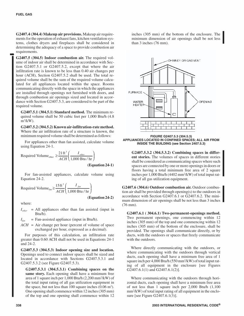
G2407.5.3 (304.5.3) Indoor opening size and location.Openings used to connect indoor spaces shall be sized andlocated in accordance with Sections G2407.5.3.1 andG2407.5.3.2 (see Figure G2407.5.3).
G2407.5.3.1 (304.5.3.1) Combining spaces on thesame story. Each opening shall have a minimum freearea of 1 square inch per 1,000 Btu/h (2,200 mm2/kW) ofthe total input rating of all gas utilization equipment inthe space, but not less than 100 square inches (0.06 m2).One opening shall commence within 12 inches (305 mm)of the top and one opening shall commence within 12
inches (305 mm) of the bottom of the enclosure. Theminimum dimension of air openings shall be not lessthan 3 inches (76 mm).
G2407.5.3.2 (304.5.3.2) Combining spaces in differ-ent stories. The volumes of spaces in different storiesshall be considered as communicating spaces where suchspaces are connected by one or more openings in doors orfloors having a total minimum free area of 2 squareinches per 1,000 Btu/h (4402 mm2/kW) of total input rat-ing of all gas utilization equipment.
G2407.6 (304.6) Outdoor combustion air. Outdoor combus-tion air shall be provided through opening(s) to the outdoors inaccordance with Section G2407.6.1 or G2407.6.2. The mini-mum dimension of air openings shall be not less than 3 inches(76 mm).
G2407.6.1 ( 304.6.1) Two-permanent-openings method.Two permanent openings, one commencing within 12inches (305 mm) of the top and one commencing within 12inches (305 mm) of the bottom of the enclosure, shall beprovided. The openings shall communicate directly, or byducts, with the outdoors or spaces that freely communicatewith the outdoors.
Where directly communicating with the outdoors, orwhere communicating with the outdoors through verticalducts, each opening shall have a minimum free area of 1square inch per 4,000 Btu/h (550 mm2/kW) of total input rat-ing of all equipment in the enclosure [see FiguresG2407.6.1(1) and G2407.6.1(2)].
Where communicating with the outdoors through hori-zontal ducts, each opening shall have a minimum free areaof not less than 1 square inch per 2,000 Btu/h (1,100mm2/kW) of total input rating of all equipment in the enclo-sure [see Figure G2407.6.1(3)].
338 2003 INTERNATIONAL RESIDENTIAL CODE®
FUEL GAS
FIGURE G2407.5.3 (304.5.3)APPLIANCES LOCATED IN CONFINED SPACES; ALL AIR FROM
INSIDE THE BUILDING (see Section 2407.5.3)
➡

G2407.6.2 (304.6.2) One-permanent-opening method.One permanent opening, commencing within 12 inches(305 mm) of the top of the enclosure, shall be provided. Theequipment shall have clearances of at least 1 inch (25 mm)from the sides and back and 6 inches (152 mm) from thefront of the appliance. The opening shall directly communi-cate with the outdoors or through a vertical or horizontalduct to the outdoors or spaces that freely communicate withthe outdoors [see Figure G2407.6.2] and shall have a mini-mum free area of 1 square inch per 3,000 Btu/h (734mm2/kW) of the total input rating of all equipment located inthe enclosure, and not less than the sum of the areas of allvent connectors in the space.
G2407.7 (304.7) Combination indoor and outdoor combus-tion air. The use of a combination of indoor and outdoor com-bustion air shall be in accordance with Sections G2407.7.1through G2407.7.3.
G2407.7.1 (304.7.1) Indoor openings. Where used, open-ings connecting the interior spaces shall comply with Sec-tion G2407.5.3.
G2407.7.2 (304.7.2) Outdoor opening location. Outdooropening(s) shall be located in accordance with SectionG2407.6.
G2407.7.3 (304.7.3) Outdoor opening(s) size. The out-door opening(s) size shall be calculated in accordance withthe following:
1. The ratio of interior spaces shall be the available vol-ume of all communicating spaces divided by the re-quired volume.
2. The outdoor size reduction factor shall be one minusthe ratio of interior spaces.
3. The minimum size of outdoor opening(s) shall be thefull size of outdoor opening(s) calculated in accor-dance with Section G2407.6, multiplied by the reduc-tion factor. The minimum dimension of air openingsshall be not less than 3 inches (76 mm).
G2407.8 (304.8) Engineered installations. Engineered com-bustion air installations shall provide an adequate supply ofcombustion, ventilation and dilution air and shall be approved.
G2407.9 (304.9) Mechanical combustion air supply. Whereall combustion air is provided by a mechanical air supply sys-tem, the combustion air shall be supplied from the outdoors at arate not less than 0.35 cubic feet per minute per 1,000 Btu/h(0.034 m3/min per kW) of total input rating of all appliances lo-cated within the space.
G2407.9.1 (304.9.1) Makeup air. Where exhaust fans areinstalled, makeup air shall be provided to replace the ex-hausted air.
G2407.9.2 (304.9.2) Appliance interlock. Each of the ap-pliances served shall be interlocked with the mechanical airsupply system to prevent main burner operation when themechanical air supply system is not in operation.
G2407.9.3 (304.9.3) Combined combustion air and ven-tilation air system. Where combustion air is provided bythe building’s mechanical ventilation system, the systemshall provide the specified combustion air rate in addition tothe required ventilation air.
G2407.10 (304.10) Louvers and grilles. The required size ofopenings for combustion, ventilation and dilution air shall bebased on the net free area of each opening. Where the free areathrough a design of louver or grille is known, it shall be used incalculating the size opening required to provide the free areaspecified. Where the design and free area are not known, it shall
2003 INTERNATIONAL RESIDENTIAL CODE® 339
FUEL GAS
FIGURE G2407.6.1(1) [304.6.1(1)]APPLIANCES LOCATED IN CONFINED SPACES; ALL AIR FROM OUTDOOR-INLET AIR FROM VENTILATED
CRAWL SPACE AND OUTLET AIR TO VENTILATED ATTIC. SEE SECTION G2407.6.1.
➡

340 2003 INTERNATIONAL RESIDENTIAL CODE®
FUEL GAS
FIGURE G2407.6.1(3) [304.6.1(3)]APPLIANCES LOCATED IN CONFINED SPACES; ALL AIR FROM OUTDOORS.
SEE SECTION G2407.6.1.
For SI: 1 foot = 304.8 mm.
FIGURE G2407.6.1(2) [304.6.1(2)]APPLIANCES LOCATED IN CONFINED SPACES; ALL AIR FROM OUTDOORS THROUGH
VENTILATED ATTIC. SEE SECTION G2407.6.1.

be assumed that wood louvers will have 25-percent free areaand metal louvers and grilles will have 75-percent free area.Nonmotorized louvers and grilles shall be fixed in the open po-sition. Motorized louvers shall be interlocked with the equip-ment so that they are proven to be in the full open position priorto main burner ignition and during main burner operation.Means shall be provided to prevent the main burner from ignit-ing if the louvers fail to open during burner start-up and to shutdown the main burner if the louvers close during operation.
G2407.11 (304.11) Combustion air ducts. Combustion airducts shall comply with all of the following:
1. Ducts shall be of galvanized steel complying with Chap-ter 16 or of equivalent corrosion-resistant material ap-proved for this application.
Exception: Within dwellings units, unobstructed studand joist spaces shall not be prohibited from convey-ing combustion air, provided that not more than onerequired fireblock is removed.
2. Ducts shall terminate in an unobstructed space allowingfree movement of combustion air to the appliances.
3. Ducts shall serve a single enclosure.
4. Ducts shall not serve both upper and lower combustionair openings where both such openings are used. The sep-aration between ducts serving upper and lower combus-tion air openings shall be maintained to the source ofcombustion air.
5. Ducts shall not be screened where terminating in an atticspace.
6. Horizontal upper combustion air ducts shall not slopedownward toward the source of combustion air.
7. The remaining space surrounding a chimney liner, gasvent, special gas vent or plastic piping installed within amasonry, metal or factory-built chimney shall not beused to supply combustion air.
Exception: Direct-vent gas-fired appliances de-signed for installation in a solid fuel-burning fireplacewhere installed in accordance with the listing and themanufacturer’s instructions.
8. Combustion air intake openings located on the exteriorof a building shall have the lowest side of such openingslocated not less than 12 inches (305 mm) vertically fromthe adjoining grade level.
G2407.12 (304.12) Protection from fumes and gases. Wherecorrosive or flammable process fumes or gases, other thanproducts of combustion, are present, means for the disposal ofsuch fumes or gases shall be provided. Such fumes or gases in-clude carbon monoxide, hydrogen sulfide, ammonia, chlorineand halogenated hydrocarbons.
In barbershops, beauty shops and other facilities wherechemicals that generate corrosive or flammable products, suchas aerosol sprays, are routinely used, nondirect-vent-type ap-pliances shall be located in an equipment room separated orpartitioned off from other areas with provisions for combustionair and dilution air from the outdoors. Direct-vent appliancesshall be installed in accordance with the appliance manufac-turer's installation instructions.
SECTION G2408 (305)INSTALLATION
G2408.1 (305.1) General. Equipment and appliances shall beinstalled as required by the terms of their approval, in accor-dance with the conditions of listing, the manufacturer’s instruc-
2003 INTERNATIONAL RESIDENTIAL CODE® 341
FUEL GAS
FIGURE G2407.6.2 [304.6.2]APPLIANCES LOCATED IN CONFINED SPACES; SINGLE COMBUSTION AIR OPENING.
SEE SECTION G2407.6.2.

tions and this code. Manufacturers’ installation instructionsshall be available on the job site at the time of inspection.Where a code provision is less restrictive than the conditions ofthe listing of the equipment or appliance or the manufacturer’sinstallation instructions, the conditions of the listing and themanufacturer’s installation instructions shall apply.
Unlisted appliances approved in accordance with Section2404.3 shall be limited to uses recommended by the manufac-turer and shall be installed in accordance with the manufac-turer’s instructions, the provisions of this code and therequirements determined by the code official.
G2408.2 (305.3) Elevation of ignition source. Equipment andappliances having an ignition source shall be elevated such thatthe source of ignition is not less than 18 inches (457 mm) abovethe floor in hazardous locations and private garages. For thepurpose of this section, rooms or spaces that are not part of theliving space of a dwelling unit and that communicate directlywith a private garage through openings shall be considered tobe part of the private garage.
Exception: Elevation of the ignition source is not requiredfor appliances that are listed as flammable vapor resistantand for installation without elevation.
G2408.3 (305.5) Private garages. Appliances located in pri-vate garages shall be installed with a minimum clearance of 6feet (1829 mm) above the floor.
Exception: The requirements of this section shall not applywhere the appliances are protected from motor vehicle im-pact and installed in accordance with Section G2408.2.
G2408.4 (305.7) Clearances from grade. Equipment and ap-pliances installed at grade level shall be supported on a levelconcrete slab or other approved material extending above ad-joining grade or shall be suspended a minimum of 6 inches(152 mm) above adjoining grade.
G2408.5 (305.8) Clearances to combustible construction.Heat-producing equipment and appliances shall be installed tomaintain the required clearances to combustible constructionas specified in the listing and manufacturer’s instructions. Suchclearances shall be reduced only in accordance with SectionG2409. Clearances to combustibles shall include such consid-erations as door swing, drawer pull, overhead projections orshelving and window swing. Devices, such as door stops orlimits and closers, shall not be used to provide the requiredclearances.
SECTION G2409 (308)CLEARANCE REDUCTION
G2409.1 (308.1) Scope. This section shall govern the reduc-tion in required clearances to combustible materials and com-bustible assemblies for chimneys, vents, appliances, devicesand equipment.
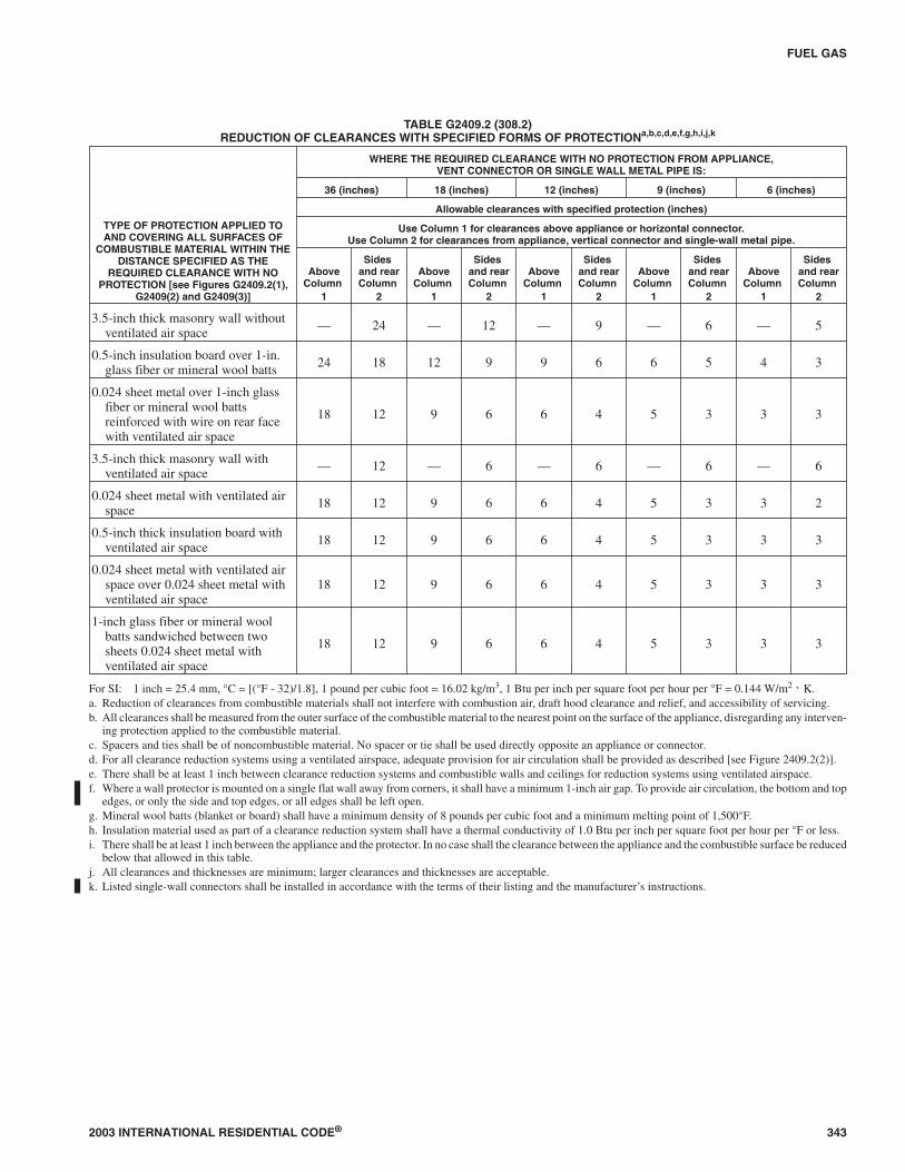
G2409.2 (308.2) Reduction table. The allowable clearance re-duction shall be based on one of the methods specified in TableG2409.2 or shall utilize an assembly listed for such application.Where required clearances are not listed in Table G2409.2, thereduced clearances shall be determined by linear interpolationbetween the distances listed in the table. Reduced clearances
shall not be derived by extrapolation below the range of the ta-ble. The reduction of the required clearances to combustiblesfor listed and labeled appliances and equipment shall be in ac-cordance with the requirements of this section except that suchclearances shall not be reduced where reduction is specificallyprohibited by the terms of the appliance or equipment listing[see Figures G2409.2(1) and G2409.2(2)].
G2409.3 (308.3) Clearances for indoor air-conditioningequipment. Clearance requirements for indoor air-condition-ing equipment shall comply with Sections G2409.3.1 throughG2409.3.5.
G2409.3.1 (308.3.1) Equipment installed in rooms thatare large in comparison with the size of the equipment.Air-conditioning equipment installed in rooms that are largein comparison with the size of the equipment shall be in-stalled with clearances per the terms of their listing and themanufacturer’s instructions.
G2409.3.2 (308.3.2) Equipment installed in rooms thatare not large in comparison with the size of the equip-ment. Air-conditioning equipment installed in rooms thatare not large (such as alcoves and closets) in comparisonwith the size of the equipment shall be listed for such instal-lations and installed in accordance with the manufacturer’sinstructions. Listed clearances shall not be reduced by theprotection methods described in Table G2409.2, regardlessof whether the enclosure is of combustible or noncombusti-ble material.
G2409.3.3 (308.3.3) Clearance reduction. Air-condition-ing equipment installed in rooms that are large in compari-son with the size of the equipment shall be permitted to beinstalled with reduced clearances to combustible materialprovided the combustible material or equipment is protectedas described in Table G2409.2
G2409.3.4 (308.3.4) Plenum clearances. Where the fur-nace plenum is adjacent to plaster on metal lath or noncom-bustible material attached to combustible material, theclearance shall be measured to the surface of the plaster orother noncombustible finish where the clearance specifiedis 2 inches (51 mm) or less.
G2409.3.5 (308.3.5) Clearance from supply ducts.Air-conditioning equipment shall have the clearance fromsupply ducts within 3 feet (914 mm) of the furnace plenumbe not less than that specified from the furnace plenum. Noclearance is necessary beyond this distance.
G2409.4 (308.4) Central heating boilers and furnaces.Clearance requirements for central heating boilers and fur-naces shall comply with Sections G2409.4.1 throughG2409.4.6. The clearance to this equipment shall not interferewith combustion air, draft hood clearance and relief, and acces-sibility for servicing.
G2409.4.1 (308.4.1) Equipment installed in rooms thatare large in comparison with the size of the equipment.Central heating furnaces and low-pressure boilers installedin rooms large in comparison with the size of the equipmentshall be installed with clearances per terms of their listingand the manufacturer’s instructions.
342 2003 INTERNATIONAL RESIDENTIAL CODE®
FUEL GAS
2003 INTERNATIONAL RESIDENTIAL CODE® 343
FUEL GAS
TABLE G2409.2 (308.2)REDUCTION OF CLEARANCES WITH SPECIFIED FORMS OF PROTECTIONa,b,c,d,e,f,g,h,i,j,k
TYPE OF PROTECTION APPLIED TOAND COVERING ALL SURFACES OF
COMBUSTIBLE MATERIAL WITHIN THEDISTANCE SPECIFIED AS THE
REQUIRED CLEARANCE WITH NOPROTECTION [see Figures G2409.2(1),
G2409(2) and G2409(3)]
WHERE THE REQUIRED CLEARANCE WITH NO PROTECTION FROM APPLIANCE,VENT CONNECTOR OR SINGLE WALL METAL PIPE IS:
36 (inches) 18 (inches) 12 (inches) 9 (inches) 6 (inches)
Allowable clearances with specified protection (inches)
Use Column 1 for clearances above appliance or horizontal connector.Use Column 2 for clearances from appliance, vertical connector and single-wall metal pipe.
AboveColumn
1
Sidesand rearColumn
2
AboveColumn
1
Sidesand rearColumn
2
AboveColumn
1
Sidesand rearColumn
2
AboveColumn
1
Sidesand rearColumn
2
AboveColumn
1
Sidesand rearColumn
2
3.5-inch thick masonry wall withoutventilated air space — 24 — 12 — 9 — 6 — 5
0.5-inch insulation board over 1-in.glass fiber or mineral wool batts 24 18 12 9 9 6 6 5 4 3
0.024 sheet metal over 1-inch glassfiber or mineral wool battsreinforced with wire on rear facewith ventilated air space
18 12 9 6 6 4 5 3 3 3
3.5-inch thick masonry wall withventilated air space — 12 — 6 — 6 — 6 — 6
0.024 sheet metal with ventilated airspace 18 12 9 6 6 4 5 3 3 2
0.5-inch thick insulation board withventilated air space 18 12 9 6 6 4 5 3 3 3
0.024 sheet metal with ventilated airspace over 0.024 sheet metal withventilated air space
18 12 9 6 6 4 5 3 3 3
1-inch glass fiber or mineral woolbatts sandwiched between twosheets 0.024 sheet metal withventilated air space
18 12 9 6 6 4 5 3 3 3
For SI: 1 inch = 25.4 mm, °C = [(°F - 32)/1.8], 1 pound per cubic foot = 16.02 kg/m3, 1 Btu per inch per square foot per hour per °F = 0.144 W/m2 ⋅ K.a. Reduction of clearances from combustible materials shall not interfere with combustion air, draft hood clearance and relief, and accessibility of servicing.b. All clearances shall be measured from the outer surface of the combustible material to the nearest point on the surface of the appliance, disregarding any interven-
ing protection applied to the combustible material.c. Spacers and ties shall be of noncombustible material. No spacer or tie shall be used directly opposite an appliance or connector.d. For all clearance reduction systems using a ventilated airspace, adequate provision for air circulation shall be provided as described [see Figure 2409.2(2)].e. There shall be at least 1 inch between clearance reduction systems and combustible walls and ceilings for reduction systems using ventilated airspace.f. Where a wall protector is mounted on a single flat wall away from corners, it shall have a minimum 1-inch air gap. To provide air circulation, the bottom and top
edges, or only the side and top edges, or all edges shall be left open.g. Mineral wool batts (blanket or board) shall have a minimum density of 8 pounds per cubic foot and a minimum melting point of 1,500°F.h. Insulation material used as part of a clearance reduction system shall have a thermal conductivity of 1.0 Btu per inch per square foot per hour per °F or less.i. There shall be at least 1 inch between the appliance and the protector. In no case shall the clearance between the appliance and the combustible surface be reduced
below that allowed in this table.j. All clearances and thicknesses are minimum; larger clearances and thicknesses are acceptable.k. Listed single-wall connectors shall be installed in accordance with the terms of their listing and the manufacturer’s instructions.

344 2003 INTERNATIONAL RESIDENTIAL CODE®
FUEL GAS
For SI: 1 inch = 25.4 mm.
FIGURE G2409.2(2) [308.2(2)]WALL PROTECTOR CLEARANCE REDUCTION SYSTEM
NOTES:“A” equals the clearance with no protection.“B” equals the reduced clearance permitted in accordance with Table G2409.2. The protection applied to the construction using combustible material shall extend farenough in each direction to make “C” equal to “A.”
FIGURE G2409.2(1) [308.2(1)]EXTENT OF PROTECTION NECESSARY TO REDUCE CLEARANCES
FROM GAS EQUIPMENT OR VENT CONNECTORS

G2409.4.2 (308.4.2) Equipment installed in rooms thatare not large in comparison with the size of the equip-ment. Central heating furnaces and low-pressure boilers in-stalled in rooms that are not large (such as alcoves andclosets) in comparison with the size of the equipment shallbe listed for such installations. Listed clearances shall not bereduced by the protection methods described in TableG2409.2 and illustrated in Figures G2409.2(1) andG2409.2(2), regardless of whether the enclosure is of com-bustible or noncombustible material.
G2409.4.3 (308.4.3) Clearance reduction. Central heatingfurnaces and low-pressure boilers installed in rooms that arelarge in comparison with the size of the equipment shall bepermitted to be installed with reduced clearances to com-bustible material provided the combustible material orequipment is protected as described in Table G2409.2.
G2409.4.4 (308.4.5) Plenum clearances. Where the fur-nace plenum is adjacent to plaster on metal lath or noncom-bustible material attached to combustible material, theclearance shall be measured to the surface of the plaster orother noncombustible finish where the clearance specifiedis 2 inches (51 mm) or less.
G2409.4.5 (308.4.6) Clearance from supply ducts. Cen-tral-heating furnaces shall have the clearance from supplyducts within 3 feet (914 mm) of the furnace plenum be notless than that specified from the furnace plenum. No clear-ance is necessary beyond this distance.
G2409.4.6 (308.4.4) Clearance for servicing equipment.Front clearance shall be sufficient for servicing the burnerand the furnace or boiler.
SECTION G2410 (309)ELECTRICAL
G2410.1 (309.1) Grounding. Gas piping shall not be used as agrounding electrode.
G2410.2 (309.2) Connections. Electrical connections be-tween gas utilization equipment and the building wiring, in-cluding the grounding of the equipment, shall conform toChapters 33 through 42.
SECTION G2411 (310)ELECTRICAL BONDING
G2411.1 (310.1) Gas pipe bonding. Each above-ground por-tion of a gas piping system that is likely to become energizedshall be electrically continuous and bonded to an effectiveground-fault current path. Gas piping shall be considered to bebonded where it is connected to gas utilization equipment thatis connected to the equipment grounding conductor of the cir-cuit supplying that equipment.
SECTION G2412 (401)GENERAL
G2412.1 (401.1) Scope. This chapter shall govern the design,installation, modification and maintenance of piping systems.The applicability of this code to piping systems extends from
the point of delivery to the connections with the equipment andincludes the design, materials, components, fabrication, as-sembly, installation, testing, inspection, operation and mainte-nance of such piping systems.
G2412.1.1 (401.1.1) Utility piping systems located withinbuildings. Utility service piping located within buildingsshall be installed in accordance with the structural safetyand fire protection provisions of this code.
G2412.2 (401.2) Liquefied petroleum gas storage. The stor-age system for liquefied petroleum gas shall be designed andinstalled in accordance with the International Fire Code andNFPA 58.
G2412.3 (401.3) Modifications to existing systems. In modi-fying or adding to existing piping systems, sizes shall be main-tained in accordance with this chapter.
G2412.4 (401.4) Additional appliances. Where an additionalappliance is to be served, the existing piping shall be checked todetermine if it has adequate capacity for all appliances served.If inadequate, the existing system shall be enlarged as requiredor separate piping of adequate capacity shall be provided.
G2412.5 (401.5) Identification. For other than black steelpipe, exposed piping shall be identified by a yellow labelmarked “Gas” in black letters. The marking shall be spaced atintervals not exceeding 5 feet (1524 mm). The marking shallnot be required on pipe located in the same room as the equip-ment served.
G2412.6 (401.6) Interconnections. Where two or more me-ters are installed on the same premises, but supply separateconsumers, the piping systems shall not be interconnected onthe outlet side of the meters.
G2412.7 (401.7) Piping meter identification. Piping frommultiple meter installations shall be marked with an approvedpermanent identification by the installer so that the piping sys-tem supplied by each meter is readily identifiable.
G2412.8 (401.8) Minimum sizes. All pipe utilized for the in-stallation, extension and alteration of any piping system shallbe sized to supply the full number of outlets for the intendedpurpose and shall be sized in accordance with Section G2413.
SECTION G2413 (402)PIPE SIZING
G2413.1 (402.1) General considerations. Piping systemsshall be of such size and so installed as to provide a supply ofgas sufficient to meet the maximum demand without undueloss of pressure between the point of delivery and the gas utili-zation equipment.
G2413.2 (402.2) Maximum gas demand. The volume of gasto be provided in cubic feet per hour shall be determined di-rectly from the manufacturer’s input ratings of the gas utiliza-tion equipment served. Where input rating is not indicated, thegas supplier, equipment manufacturer or a qualified agencyshall be contacted, or the rating from Table G2413.2 shall beused for estimating the volume of gas to be supplied.
The total connected hourly load shall be used as the basis forpiping sizing assuming that all equipment could be operating at
2003 INTERNATIONAL RESIDENTIAL CODE® 345
FUEL GAS
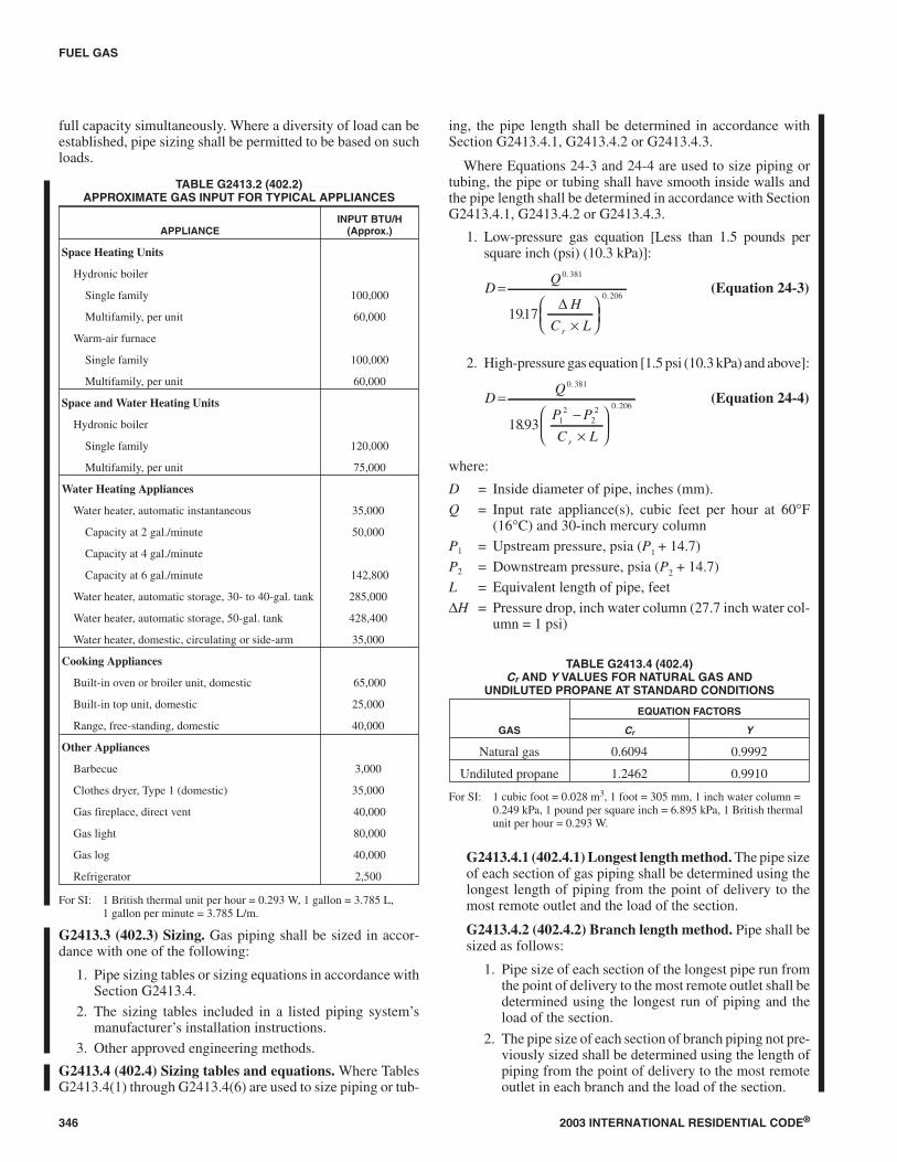
full capacity simultaneously. Where a diversity of load can beestablished, pipe sizing shall be permitted to be based on suchloads.
TABLE G2413.2 (402.2)APPROXIMATE GAS INPUT FOR TYPICAL APPLIANCES
APPLIANCEINPUT BTU/H
(Approx.)
Space Heating Units
Hydronic boiler
Single family 100,000
Multifamily, per unit 60,000
Warm-air furnace
Single family 100,000
Multifamily, per unit 60,000
Space and Water Heating Units
Hydronic boiler
Single family 120,000
Multifamily, per unit 75,000
Water Heating Appliances
Water heater, automatic instantaneous 35,000
Capacity at 2 gal./minute 50,000
Capacity at 4 gal./minute
Capacity at 6 gal./minute 142,800
Water heater, automatic storage, 30- to 40-gal. tank 285,000
Water heater, automatic storage, 50-gal. tank 428,400
Water heater, domestic, circulating or side-arm 35,000
Cooking Appliances
Built-in oven or broiler unit, domestic 65,000
Built-in top unit, domestic 25,000
Range, free-standing, domestic 40,000
Other Appliances
Barbecue 3,000
Clothes dryer, Type 1 (domestic) 35,000
Gas fireplace, direct vent 40,000
Gas light 80,000
Gas log 40,000
Refrigerator 2,500
For SI: 1 British thermal unit per hour = 0.293 W, 1 gallon = 3.785 L,1 gallon per minute = 3.785 L/m.
G2413.3 (402.3) Sizing. Gas piping shall be sized in accor-dance with one of the following:
1. Pipe sizing tables or sizing equations in accordance withSection G2413.4.
2. The sizing tables included in a listed piping system’smanufacturer’s installation instructions.
3. Other approved engineering methods.
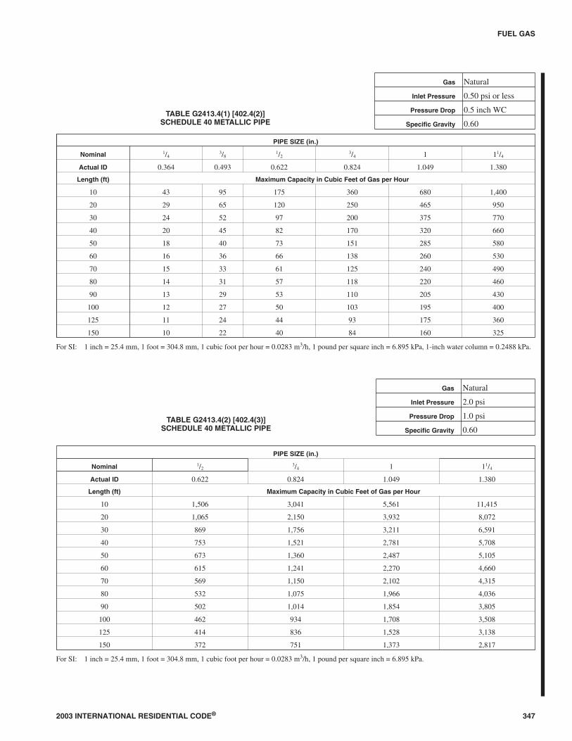
G2413.4 (402.4) Sizing tables and equations. Where TablesG2413.4(1) through G2413.4(6) are used to size piping or tub-
ing, the pipe length shall be determined in accordance withSection G2413.4.1, G2413.4.2 or G2413.4.3.
Where Equations 24-3 and 24-4 are used to size piping ortubing, the pipe or tubing shall have smooth inside walls andthe pipe length shall be determined in accordance with SectionG2413.4.1, G2413.4.2 or G2413.4.3.
1. Low-pressure gas equation [Less than 1.5 pounds persquare inch (psi) (10.3 kPa)]:
DQ
H
C Lr
=
×
0 381
0 206
1917
.
.
.∆
(Equation 24-3)
2. High-pressure gas equation [1.5 psi (10.3 kPa) and above]:
DQ
P P
C Lr
=−×
0 381
12
22 0 206
1893
.
.
.
(Equation 24-4)
where:
D = Inside diameter of pipe, inches (mm).
Q = Input rate appliance(s), cubic feet per hour at 60°F(16°C) and 30-inch mercury column
P1 = Upstream pressure, psia (P1 + 14.7)
P2 = Downstream pressure, psia (P2 + 14.7)
L = Equivalent length of pipe, feet
∆H = Pressure drop, inch water column (27.7 inch water col-umn = 1 psi)
TABLE G2413.4 (402.4)Cr AND Y VALUES FOR NATURAL GAS AND
UNDILUTED PROPANE AT STANDARD CONDITIONS
GAS
EQUATION FACTORS
Cr Y
Natural gas 0.6094 0.9992
Undiluted propane 1.2462 0.9910
For SI: 1 cubic foot = 0.028 m3, 1 foot = 305 mm, 1 inch water column =0.249 kPa, 1 pound per square inch = 6.895 kPa, 1 British thermalunit per hour = 0.293 W.
G2413.4.1 (402.4.1) Longest length method. The pipe sizeof each section of gas piping shall be determined using thelongest length of piping from the point of delivery to themost remote outlet and the load of the section.
G2413.4.2 (402.4.2) Branch length method. Pipe shall besized as follows:
1. Pipe size of each section of the longest pipe run fromthe point of delivery to the most remote outlet shall bedetermined using the longest run of piping and theload of the section.
2. The pipe size of each section of branch piping not pre-viously sized shall be determined using the length ofpiping from the point of delivery to the most remoteoutlet in each branch and the load of the section.
346 2003 INTERNATIONAL RESIDENTIAL CODE®
FUEL GAS
2003 INTERNATIONAL RESIDENTIAL CODE® 347
FUEL GAS
TABLE G2413.4(1) [402.4(2)]SCHEDULE 40 METALLIC PIPE
Gas Natural
Inlet Pressure 0.50 psi or less
Pressure Drop 0.5 inch WC
Specific Gravity 0.60
PIPE SIZE (in.)
Nominal 1/43/8
1/23/4 1 11/4
Actual ID 0.364 0.493 0.622 0.824 1.049 1.380
Length (ft) Maximum Capacity in Cubic Feet of Gas per Hour
10 43 95 175 360 680 1,400
20 29 65 120 250 465 950
30 24 52 97 200 375 770
40 20 45 82 170 320 660
50 18 40 73 151 285 580
60 16 36 66 138 260 530
70 15 33 61 125 240 490
80 14 31 57 118 220 460
90 13 29 53 110 205 430
100 12 27 50 103 195 400
125 11 24 44 93 175 360
150 10 22 40 84 160 325
For SI: 1 inch = 25.4 mm, 1 foot = 304.8 mm, 1 cubic foot per hour = 0.0283 m3/h, 1 pound per square inch = 6.895 kPa, 1-inch water column = 0.2488 kPa.
TABLE G2413.4(2) [402.4(3)]SCHEDULE 40 METALLIC PIPE
Gas Natural
Inlet Pressure 2.0 psi
Pressure Drop 1.0 psi
Specific Gravity 0.60
PIPE SIZE (in.)
Nominal 1/23/4 1 11/4
Actual ID 0.622 0.824 1.049 1.380
Length (ft) Maximum Capacity in Cubic Feet of Gas per Hour
10 1,506 3,041 5,561 11,415
20 1,065 2,150 3,932 8,072
30 869 1,756 3,211 6,591
40 753 1,521 2,781 5,708
50 673 1,360 2,487 5,105
60 615 1,241 2,270 4,660
70 569 1,150 2,102 4,315
80 532 1,075 1,966 4,036
90 502 1,014 1,854 3,805
100 462 934 1,708 3,508
125 414 836 1,528 3,138
150 372 751 1,373 2,817
For SI: 1 inch = 25.4 mm, 1 foot = 304.8 mm, 1 cubic foot per hour = 0.0283 m3/h, 1 pound per square inch = 6.895 kPa.

348 2003 INTERNATIONAL RESIDENTIAL CODE®
FUEL GAS
TABLE G2413.4(3) [402.4(8)]SEMI-RIGID COPPER TUBING
Gas Natural
Inlet Pressure 0.5 psi or less
Pressure Drop 0.5 inch WC
Specific Gravity 0.60
TUBE SIZE (in.)
NominalK & L 1/4
3/81/2
5/83/4 1
ACR 3/81/2
5/83/4
7/8 11/8
Outside 0.375 0.500 0.625 0.750 0.875 1.125
Inside 0.305 0.402 0.527 0.652 0.745 0.995
Length (ft) Maximum Capacity in Cubic Feet of Gas per Hour
10 27 55 111 195 276 590
20 18 38 77 134 190 406
30 15 30 61 107 152 326
40 13 26 53 92 131 279
50 11 23 47 82 116 247
60 10 21 42 74 105 224
70 9.3 19 39 68 96 206
80 8.6 18 36 63 90 192
90 8.1 17 34 59 84 180
100 7.6 16 32 56 79 170
125 6.8 14 28 50 70 151
150 6.1 13 26 45 64 136
Note: Table capacities are based on Type K copper tubing inside diameter (shown), which has the smallest inside diameter of the copper tubing products.
For SI: 1 inch = 25.4 mm, 1 foot = 304.8 mm, 1 cubic foot per hour = 0.0283 m3/h, 1 pound per square inch = 6.895 kPa, 1-inch water column = 0.2488 kPa.
2003 INTERNATIONAL RESIDENTIAL CODE® 349
FUEL GAS
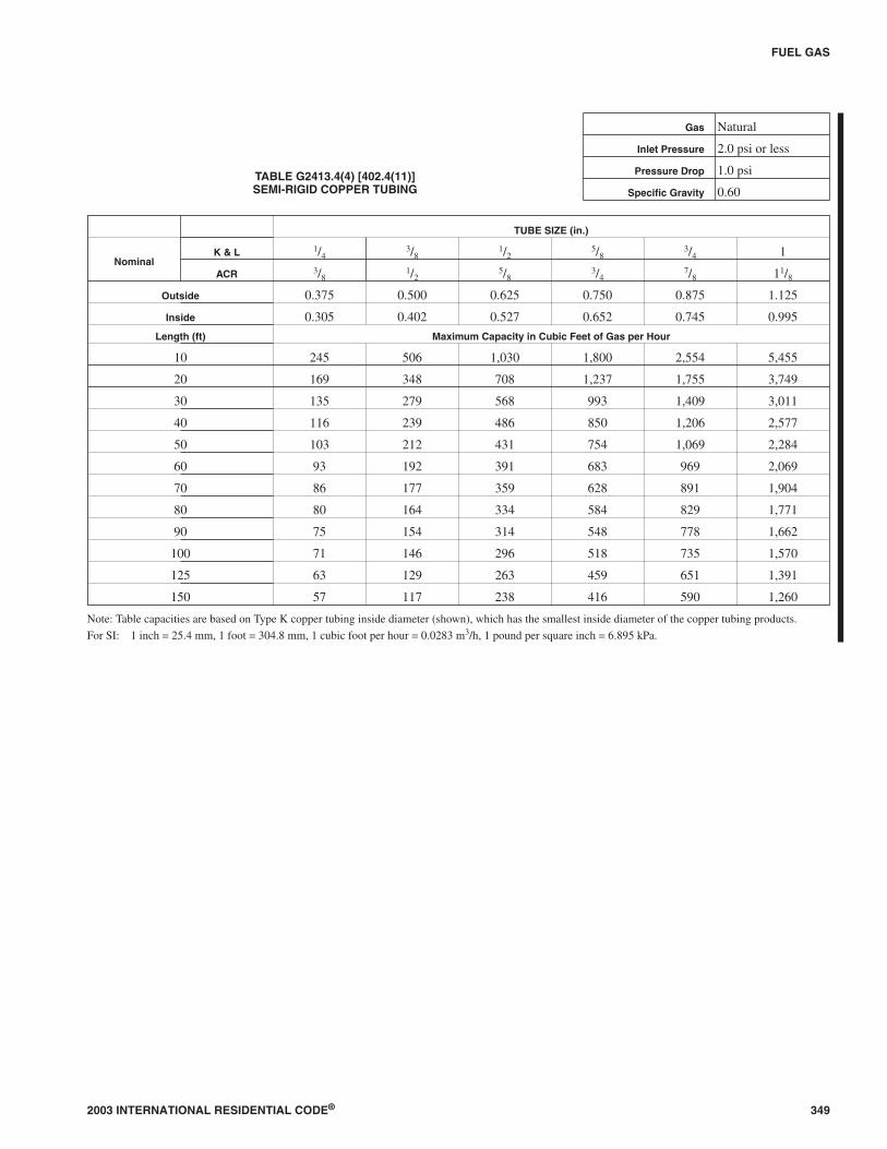
TABLE G2413.4(4) [402.4(11)]SEMI-RIGID COPPER TUBING
Gas Natural
Inlet Pressure 2.0 psi or less
Pressure Drop 1.0 psi
Specific Gravity 0.60
TUBE SIZE (in.)
NominalK & L 1/4
3/81/2
5/83/4 1
ACR 3/81/2
5/83/4
7/8 11/8
Outside 0.375 0.500 0.625 0.750 0.875 1.125
Inside 0.305 0.402 0.527 0.652 0.745 0.995
Length (ft) Maximum Capacity in Cubic Feet of Gas per Hour
10 245 506 1,030 1,800 2,554 5,455
20 169 348 708 1,237 1,755 3,749
30 135 279 568 993 1,409 3,011
40 116 239 486 850 1,206 2,577
50 103 212 431 754 1,069 2,284
60 93 192 391 683 969 2,069
70 86 177 359 628 891 1,904
80 80 164 334 584 829 1,771
90 75 154 314 548 778 1,662
100 71 146 296 518 735 1,570
125 63 129 263 459 651 1,391
150 57 117 238 416 590 1,260
Note: Table capacities are based on Type K copper tubing inside diameter (shown), which has the smallest inside diameter of the copper tubing products.
For SI: 1 inch = 25.4 mm, 1 foot = 304.8 mm, 1 cubic foot per hour = 0.0283 m3/h, 1 pound per square inch = 6.895 kPa.
350 2003 INTERNATIONAL RESIDENTIAL CODE®
FUEL GAS
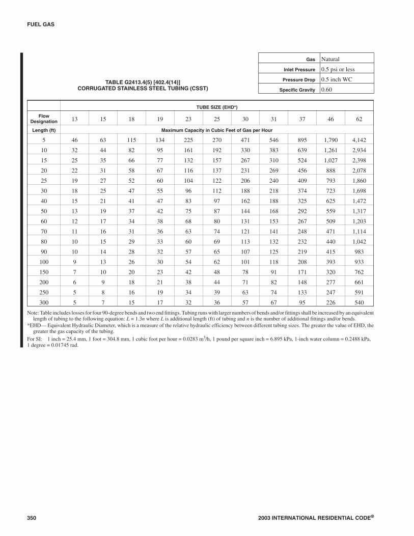
TABLE G2413.4(5) [402.4(14)]CORRUGATED STAINLESS STEEL TUBING (CSST)
Gas Natural
Inlet Pressure 0.5 psi or less
Pressure Drop 0.5 inch WC
Specific Gravity 0.60
TUBE SIZE (EHD*)
FlowDesignation 13 15 18 19 23 25 30 31 37 46 62
Length (ft) Maximum Capacity in Cubic Feet of Gas per Hour
5 46 63 115 134 225 270 471 546 895 1,790 4,142
10 32 44 82 95 161 192 330 383 639 1,261 2,934
15 25 35 66 77 132 157 267 310 524 1,027 2,398
20 22 31 58 67 116 137 231 269 456 888 2,078
25 19 27 52 60 104 122 206 240 409 793 1,860
30 18 25 47 55 96 112 188 218 374 723 1,698
40 15 21 41 47 83 97 162 188 325 625 1,472
50 13 19 37 42 75 87 144 168 292 559 1,317
60 12 17 34 38 68 80 131 153 267 509 1,203
70 11 16 31 36 63 74 121 141 248 471 1,114
80 10 15 29 33 60 69 113 132 232 440 1,042
90 10 14 28 32 57 65 107 125 219 415 983
100 9 13 26 30 54 62 101 118 208 393 933
150 7 10 20 23 42 48 78 91 171 320 762
200 6 9 18 21 38 44 71 82 148 277 661
250 5 8 16 19 34 39 63 74 133 247 591
300 5 7 15 17 32 36 57 67 95 226 540
Note: Table includes losses for four 90-degree bends and two end fittings. Tubing runs with larger numbers of bends and/or fittings shall be increased by an equivalentlength of tubing to the following equation: L = 1.3n where L is additional length (ft) of tubing and n is the number of additional fittings and/or bends.
*EHD— Equivalent Hydraulic Diameter, which is a measure of the relative hydraulic efficiency between different tubing sizes. The greater the value of EHD, thegreater the gas capacity of the tubing.
For SI: 1 inch = 25.4 mm, 1 foot = 304.8 mm, 1 cubic foot per hour = 0.0283 m3/h, 1 pound per square inch = 6.895 kPa, 1-inch water column = 0.2488 kPa,1 degree = 0.01745 rad.

2003 INTERNATIONAL RESIDENTIAL CODE® 351
FUEL GAS
TABLE G2413.4(6) [402.4(17)]CORRUGATED STAINLESS STEEL TUBING (CSST)
Gas Natural
Inlet Pressure 2.0 psi
Pressure Drop 1.0 psi
Specific Gravity 0.60
FlowDesignation 13 15 18 19 23 25 30 31 37 46 62
Length (ft) Maximum Capacity in Cubic Feet of Gas per Hour
10 270 353 587 700 1,098 1,372 2,592 2,986 4,509 9,599 21,637
25 166 220 374 444 709 876 1,620 1,869 2,887 6,041 13,715
30 151 200 342 405 650 801 1,475 1,703 2,642 5,509 12,526
40 129 172 297 351 567 696 1,273 1,470 2,297 4,763 10,855
50 115 154 266 314 510 624 1,135 1,311 2,061 4,255 9,715
75 93 124 218 257 420 512 922 1,066 1,692 3,467 7,940
80 89 120 211 249 407 496 892 1,031 1,639 3,355 7,689
100 79 107 189 222 366 445 795 920 1,471 2,997 6,881
150 64 87 155 182 302 364 646 748 1,207 2,442 5,624
200 55 75 135 157 263 317 557 645 1,049 2,111 4,874
250 49 67 121 141 236 284 497 576 941 1,886 4,362
300 44 61 110 129 217 260 453 525 862 1,720 3,983
400 38 52 96 111 189 225 390 453 749 1,487 3,452
500 34 46 86 100 170 202 348 404 552 1,329 3,089
Notes:1. Table does not include effect of pressure drop across the line regulator. Where regulator loss exceeds 3/4 psi, DO NOT USE THIS TABLE. Consult with regulator
manufacturer for pressure drops and capacity factors. Pressure drops across a regulator may vary with flow rate.2. CAUTION: Capacities shown in table may exceed maximum capacity for a selected regulator. Consult with regulator or tubing manufacturer for guidance.3. Table includes losses for four 90-degree bends and two end fittings. Tubing runs with larger numbers of bends and/or fittings shall be increased by an equivalent
length of tubing to the following equation: L = 1.3n where L is additional length (ft) of tubing and n is the number of additional fittings and/or bends.*EHD— Equivalent Hydraulic Diameter, which is a measure of the relative hydraulic efficiency between different tubing sizes. The greater the value of EHD, the
greater the gas capacity of the tubing.
For SI: 1 inch = 25.4 mm, 1 foot = 304.8 mm, 1 cubic foot per hour = 0.0283 m3/h, 1 pound per square inch = 6.895 kPa, 1 degree = 0.01745 rad.

G2413.4.3 (402.4.3) Hybrid pressure. The pipe size foreach section of higher pressure gas piping shall be deter-mined using the longest length of piping from the point ofdelivery to the most remote line pressure regulator. The pipesize from the line pressure regulator to each outlet shall bedetermined using the length of piping from the regulator tothe most remote outlet served by the regulator.
G2413.5 (402.5) Allowable pressure drop. The design pres-sure loss in any piping system under maximum probable flowconditions, from the point of delivery to the inlet connection ofthe equipment, shall be such that the supply pressure at theequipment is greater than the minimum pressure required forproper equipment operation.
G2413.6 (402.6) Maximum design operating pressure. Themaximum design operating pressure for piping systems lo-cated inside buildings shall not exceed 5 psig (34 kPa gauge)except where one or more of the following conditions are met:
1. The piping system is welded.
2. The piping is located in a ventilated chase or otherwise en-closed for protection against accidental gas accumulation.
3. The piping is a temporary installation for buildings underconstruction.
G2413.6.1 (402.6.1) Liquefied petroleum gas systems.The operating pressure for undiluted LP-gas systems shallnot exceed 20 psig (140 kPa gauge). Buildings having sys-tems designed to operate below -5°F (-21°C) or with butaneor a propane-butane mix shall be designed to either accom-modate liquid LP-gas or prevent LP-gas vapor from con-densing back into a liquid.
SECTION G2414 (403)PIPING MATERIALS
G2414.1 (403.1) General. Materials used for piping systemsshall comply with the requirements of this chapter or shall beapproved.
G2414.2 (403.2) Used materials. Pipe, fittings, valves or othermaterials shall not be used again unless they are free of foreignmaterials and have been ascertained to be adequate for the ser-vice intended.
G2414.3 (403.3) Other materials. Material not covered by thestandards specifications listed herein shall be investigated andtested to determine that it is safe and suitable for the proposedservice, and, in addition, shall be recommended for that serviceby the manufacturer and shall be approved by the code official.
G2414.4 (403.4) Metallic pipe. Metallic pipe shall complywith Sections G2414.4.1 and G2414.4.2.
G2414.4.1 (403.4.1) Cast iron. Cast-iron pipe shall not beused.
G2414.4.2 (403.4.2) Steel. Steel and wrought-iron pipeshall be at least of standard weight (Schedule 40) and shallcomply with one of the following:
1. ASME B36.10, 10M; or
2. ASTM A 53; or
3. ASTM A 106.
G2414.5 (403.5) Metallic tubing. Seamless copper, aluminumalloy or steel tubing shall be permitted to be used with gases notcorrosive to such material.
G2414.5.1 (403.5.1) Steel tubing shall comply with ASTMA 539 or ASTM A 254.
G2414.5.2 (403.5.2) Copper tubing. Copper tubing shallcomply with standard Type K or L of ASTM B 88 or ASTMB 280.
Copper and brass tubing shall not be used if the gas con-tains more than an average of 0.3 grains of hydrogen sulfideper 100 standard cubic feet of gas (0.7 milligrams per 100 li-ters).
G2414.5.3 (403.5.4) Corrugated stainless steel tubing.Corrugated stainless steel tubing shall be tested and listed incompliance with the construction, installation and perfor-mance requirements of ANSI/AGA LC 1/CSA 6.26
G2414.6 (403.6) Plastic pipe, tubing and fittings. Plasticpipe, tubing and fittings shall be used outside underground onlyand shall conform with ASTM D 2513. Pipe to be used shall bemarked “gas” and “ASTM D 2513.”
G2414.6.1 (403.6.1) Anodeless risers. Anodeless risersshall comply with the following:
1. Factory-assembled anodeless risers shall be recom-mended by the manufacturer for the gas used and shallbe leak-tested by the manufacturer in accordance withwritten procedures.
2. Service head adapters and field-assembled anodelessrisers incorporating service head adapters shall berecommended by the manufacturer for the gas used bythe manufacturer and shall be designed certified tomeet the requirements of Category I of ASTM D2513, and U.S. Department of Transportation, Codeof Federal Regulations, Title 49, Part 192.281(e). Themanufacturer shall provide the user qualified installa-tion instructions as prescribed by the U.S. Departmentof Transportation, Code of Federal Regulations, Title49, Part 192.283(b).
G2414.6.2 (403.6.2) LP-gas systems. The use of plasticpipe, tubing and fittings in undiluted liquefied petroleumgas piping systems shall be in accordance with NFPA 58.
G2414.7 (403.7) Workmanship and defects. Pipe or tubingand fittings shall be clear and free from cutting burrs and de-fects in structure or threading, and shall be thoroughly brushed,and chip and scale blown.
Defects in pipe or tubing or fittings shall not be repaired. De-fective pipe, tubing or fittings shall be replaced. (See SectionG2417.1.2.)
G2414.8 (403.8) Protective coating. Where in contact withmaterial or atmosphere exerting a corrosive action, metallicpiping and fittings coated with a corrosion-resistant materialshall be used. External or internal coatings or linings used onpiping or components shall not be considered as addingstrength.
G2414.9 (403.9) Metallic pipe threads. Metallic pipe and fit-ting threads shall be taper pipe threads and shall comply withASME B1.20.1.
352 2003 INTERNATIONAL RESIDENTIAL CODE®
FUEL GAS
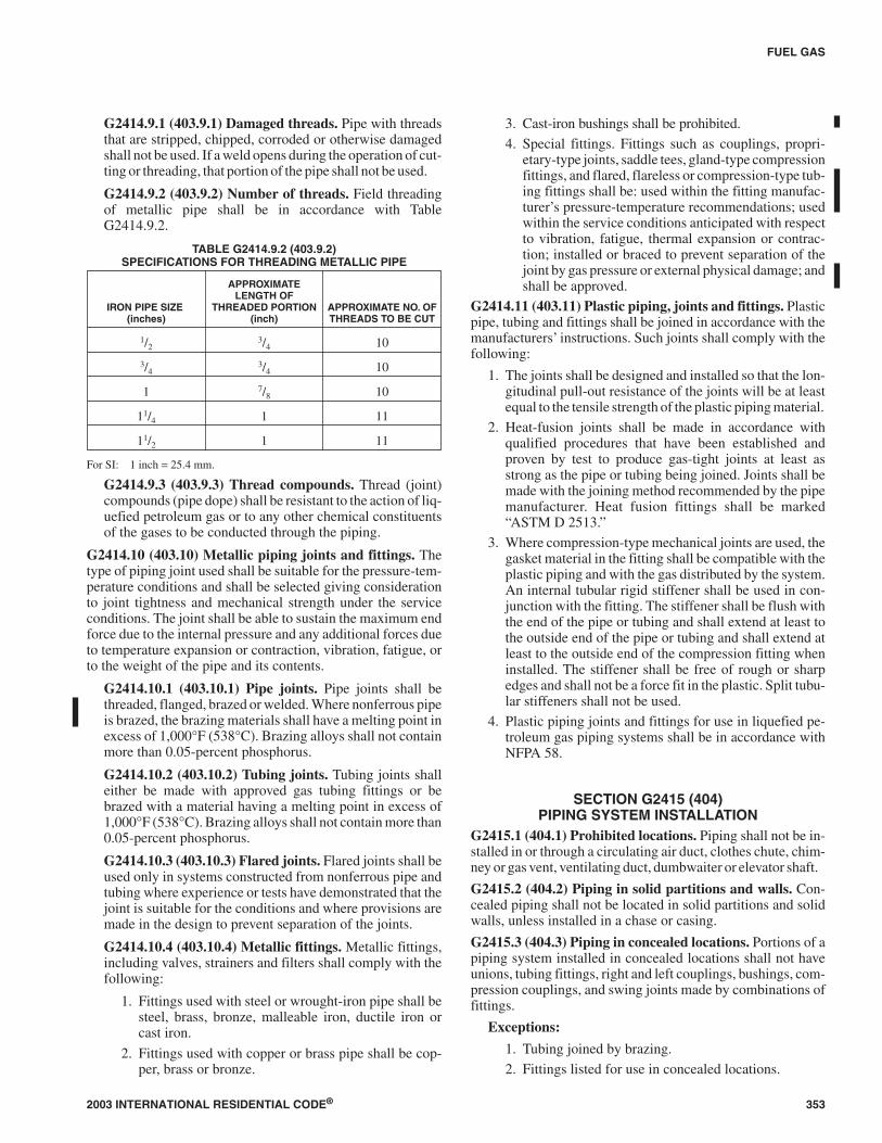
G2414.9.1 (403.9.1) Damaged threads. Pipe with threadsthat are stripped, chipped, corroded or otherwise damagedshall not be used. If a weld opens during the operation of cut-ting or threading, that portion of the pipe shall not be used.
G2414.9.2 (403.9.2) Number of threads. Field threadingof metallic pipe shall be in accordance with TableG2414.9.2.
TABLE G2414.9.2 (403.9.2)SPECIFICATIONS FOR THREADING METALLIC PIPE
IRON PIPE SIZE(inches)
APPROXIMATELENGTH OF
THREADED PORTION(inch)
APPROXIMATE NO. OFTHREADS TO BE CUT
1/23/4 10
3/43/4 10
1 7/8 10
11/4 1 11
11/2 1 11
For SI: 1 inch = 25.4 mm.
G2414.9.3 (403.9.3) Thread compounds. Thread (joint)compounds (pipe dope) shall be resistant to the action of liq-uefied petroleum gas or to any other chemical constituentsof the gases to be conducted through the piping.
G2414.10 (403.10) Metallic piping joints and fittings. Thetype of piping joint used shall be suitable for the pressure-tem-perature conditions and shall be selected giving considerationto joint tightness and mechanical strength under the serviceconditions. The joint shall be able to sustain the maximum endforce due to the internal pressure and any additional forces dueto temperature expansion or contraction, vibration, fatigue, orto the weight of the pipe and its contents.
G2414.10.1 (403.10.1) Pipe joints. Pipe joints shall bethreaded, flanged, brazed or welded. Where nonferrous pipeis brazed, the brazing materials shall have a melting point inexcess of 1,000°F (538°C). Brazing alloys shall not containmore than 0.05-percent phosphorus.
G2414.10.2 (403.10.2) Tubing joints. Tubing joints shalleither be made with approved gas tubing fittings or bebrazed with a material having a melting point in excess of1,000°F (538°C). Brazing alloys shall not contain more than0.05-percent phosphorus.
G2414.10.3 (403.10.3) Flared joints. Flared joints shall beused only in systems constructed from nonferrous pipe andtubing where experience or tests have demonstrated that thejoint is suitable for the conditions and where provisions aremade in the design to prevent separation of the joints.
G2414.10.4 (403.10.4) Metallic fittings. Metallic fittings,including valves, strainers and filters shall comply with thefollowing:
1. Fittings used with steel or wrought-iron pipe shall besteel, brass, bronze, malleable iron, ductile iron orcast iron.
2. Fittings used with copper or brass pipe shall be cop-per, brass or bronze.
3. Cast-iron bushings shall be prohibited.
4. Special fittings. Fittings such as couplings, propri-etary-type joints, saddle tees, gland-type compressionfittings, and flared, flareless or compression-type tub-ing fittings shall be: used within the fitting manufac-turer’s pressure-temperature recommendations; usedwithin the service conditions anticipated with respectto vibration, fatigue, thermal expansion or contrac-tion; installed or braced to prevent separation of thejoint by gas pressure or external physical damage; andshall be approved.
G2414.11 (403.11) Plastic piping, joints and fittings. Plasticpipe, tubing and fittings shall be joined in accordance with themanufacturers’ instructions. Such joints shall comply with thefollowing:
1. The joints shall be designed and installed so that the lon-gitudinal pull-out resistance of the joints will be at leastequal to the tensile strength of the plastic piping material.
2. Heat-fusion joints shall be made in accordance withqualified procedures that have been established andproven by test to produce gas-tight joints at least asstrong as the pipe or tubing being joined. Joints shall bemade with the joining method recommended by the pipemanufacturer. Heat fusion fittings shall be marked“ASTM D 2513.”
3. Where compression-type mechanical joints are used, thegasket material in the fitting shall be compatible with theplastic piping and with the gas distributed by the system.An internal tubular rigid stiffener shall be used in con-junction with the fitting. The stiffener shall be flush withthe end of the pipe or tubing and shall extend at least tothe outside end of the pipe or tubing and shall extend atleast to the outside end of the compression fitting wheninstalled. The stiffener shall be free of rough or sharpedges and shall not be a force fit in the plastic. Split tubu-lar stiffeners shall not be used.
4. Plastic piping joints and fittings for use in liquefied pe-troleum gas piping systems shall be in accordance withNFPA 58.
SECTION G2415 (404)PIPING SYSTEM INSTALLATION
G2415.1 (404.1) Prohibited locations. Piping shall not be in-stalled in or through a circulating air duct, clothes chute, chim-ney or gas vent, ventilating duct, dumbwaiter or elevator shaft.
G2415.2 (404.2) Piping in solid partitions and walls. Con-cealed piping shall not be located in solid partitions and solidwalls, unless installed in a chase or casing.
G2415.3 (404.3) Piping in concealed locations. Portions of apiping system installed in concealed locations shall not haveunions, tubing fittings, right and left couplings, bushings, com-pression couplings, and swing joints made by combinations offittings.
Exceptions:
1. Tubing joined by brazing.
2. Fittings listed for use in concealed locations.
2003 INTERNATIONAL RESIDENTIAL CODE® 353
FUEL GAS
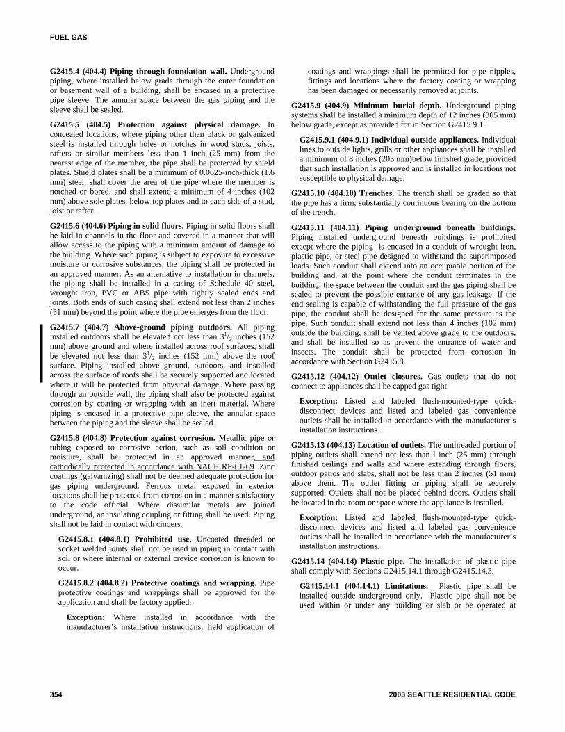
FUEL GAS
G2415.4 (404.4) Piping through foundation wall. Underground piping, where installed below grade through the outer foundation or basement wall of a building, shall be encased in a protective pipe sleeve. The annular space between the gas piping and the sleeve shall be sealed.
G2415.5 (404.5) Protection against physical damage. In concealed locations, where piping other than black or galvanized steel is installed through holes or notches in wood studs, joists, rafters or similar members less than 1 inch (25 mm) from the nearest edge of the member, the pipe shall be protected by shield plates. Shield plates shall be a minimum of 0.0625-inch-thick (1.6 mm) steel, shall cover the area of the pipe where the member is notched or bored, and shall extend a minimum of 4 inches (102 mm) above sole plates, below top plates and to each side of a stud, joist or rafter.
G2415.6 (404.6) Piping in solid floors. Piping in solid floors shall be laid in channels in the floor and covered in a manner that will allow access to the piping with a minimum amount of damage to the building. Where such piping is subject to exposure to excessive moisture or corrosive substances, the piping shall be protected in an approved manner. As an alternative to installation in channels, the piping shall be installed in a casing of Schedule 40 steel, wrought iron, PVC or ABS pipe with tightly sealed ends and joints. Both ends of such casing shall extend not less than 2 inches (51 mm) beyond the point where the pipe emerges from the floor.
G2415.7 (404.7) Above-ground piping outdoors. All piping installed outdoors shall be elevated not less than 31/2 inches (152 mm) above ground and where installed across roof surfaces, shall be elevated not less than 31/2 inches (152 mm) above the roof surface. Piping installed above ground, outdoors, and installed across the surface of roofs shall be securely supported and located where it will be protected from physical damage. Where passing through an outside wall, the piping shall also be protected against corrosion by coating or wrapping with an inert material. Where piping is encased in a protective pipe sleeve, the annular space between the piping and the sleeve shall be sealed.
G2415.8 (404.8) Protection against corrosion. Metallic pipe or tubing exposed to corrosive action, such as soil condition or moisture, shall be protected in an approved manner, and cathodically protected in accordance with NACE RP-01-69. Zinc coatings (galvanizing) shall not be deemed adequate protection for gas piping underground. Ferrous metal exposed in exterior locations shall be protected from corrosion in a manner satisfactory to the code official. Where dissimilar metals are joined underground, an insulating coupling or fitting shall be used. Piping shall not be laid in contact with cinders.
G2415.8.1 (404.8.1) Prohibited use. Uncoated threaded or socket welded joints shall not be used in piping in contact with soil or where internal or external crevice corrosion is known to occur.
G2415.8.2 (404.8.2) Protective coatings and wrapping. Pipe protective coatings and wrappings shall be approved for the application and shall be factory applied.
Exception: Where installed in accordance with the manufacturer’s installation instructions, field application of
coatings and wrappings shall be permitted for pipe nipples, fittings and locations where the factory coating or wrapping has been damaged or necessarily removed at joints.
G2415.9 (404.9) Minimum burial depth. Underground piping systems shall be installed a minimum depth of 12 inches (305 mm) below grade, except as provided for in Section G2415.9.1.
G2415.9.1 (404.9.1) Individual outside appliances. Individual lines to outside lights, grills or other appliances shall be installed a minimum of 8 inches (203 mm)below finished grade, provided that such installation is approved and is installed in locations not susceptible to physical damage.
G2415.10 (404.10) Trenches. The trench shall be graded so that the pipe has a firm, substantially continuous bearing on the bottom of the trench.
G2415.11 (404.11) Piping underground beneath buildings. Piping installed underground beneath buildings is prohibited except where the piping is encased in a conduit of wrought iron, plastic pipe, or steel pipe designed to withstand the superimposed loads. Such conduit shall extend into an occupiable portion of the building and, at the point where the conduit terminates in the building, the space between the conduit and the gas piping shall be sealed to prevent the possible entrance of any gas leakage. If the end sealing is capable of withstanding the full pressure of the gas pipe, the conduit shall be designed for the same pressure as the pipe. Such conduit shall extend not less than 4 inches (102 mm) outside the building, shall be vented above grade to the outdoors, and shall be installed so as prevent the entrance of water and insects. The conduit shall be protected from corrosion in accordance with Section G2415.8.
G2415.12 (404.12) Outlet closures. Gas outlets that do not connect to appliances shall be capped gas tight.
Exception: Listed and labeled flush-mounted-type quick-disconnect devices and listed and labeled gas convenience outlets shall be installed in accordance with the manufacturer’s installation instructions.
G2415.13 (404.13) Location of outlets. The unthreaded portion of piping outlets shall extend not less than l inch (25 mm) through finished ceilings and walls and where extending through floors, outdoor patios and slabs, shall not be less than 2 inches (51 mm) above them. The outlet fitting or piping shall be securely supported. Outlets shall not be placed behind doors. Outlets shall be located in the room or space where the appliance is installed.
Exception: Listed and labeled flush-mounted-type quick-disconnect devices and listed and labeled gas convenience outlets shall be installed in accordance with the manufacturer’s installation instructions.
G2415.14 (404.14) Plastic pipe. The installation of plastic pipe shall comply with Sections G2415.14.1 through G2415.14.3.
G2415.14.1 (404.14.1) Limitations. Plastic pipe shall be installed outside underground only. Plastic pipe shall not be used within or under any building or slab or be operated at
354 2003 SEATTLE RESIDENTIAL CODE

pressures greater than 100 psig (689 kPa) for natural gas or30 psig (207 kPa) for LP gas.
Exceptions:
1. Plastic pipe shall be permitted to terminate aboveground outside of buildings where installed in pre-manufactured anodeless risers or service headadapter risers that are installed in accordance withthat manufacturer’s installation instructions.
2. Plastic pipe shall be permitted to terminate with awall head adapter within buildings where the plas-tic pipe is inserted in a piping material for fuel gasuse in buildings.
G2415.14.2 (404.14.2) Connections. Connections madeoutside and underground between metallic and plastic pip-ing shall be made only with transition fittings categorized asCategory I in accordance with ASTM D 2513.
G2415.14.3 (404.14.3) Tracer. A yellow insulated coppertracer wire or other approved conductor shall be installedadjacent to underground nonmetallic piping. Access shallbe provided to the tracer wire or the tracer wire shall termi-nate above ground at each end of the nonmetallic piping.The tracer wire size shall not be less than 18 AWG and theinsulation type shall be suitable for direct burial.
G2415.15 (404.15) Prohibited devices. A device shall not beplaced inside the piping or fittings that will reduce thecross-sectional area or otherwise obstruct the free flow of gas.
Exception: Approved gas filters.
G2415.16 (404.16) Testing of piping. Before any system ofpiping is put in service or concealed, it shall be tested to ensurethat it is gas tight. Testing, inspection and purging of piping sys-tems shall comply with Section G2417.
SECTION G2416 (405)PIPING BENDS AND CHANGES IN DIRECTION
G2416.1 (405.1) General. Changes in direction of pipe shallbe permitted to be made by the use of fittings, factory bends orfield bends.
G2416.2 (405.2) Metallic pipe. Metallic pipe bends shall com-ply with the following:
1. Bends shall be made only with bending equipment andprocedures especially intended for that purpose.
2. All bends shall be smooth and free from buckling, cracksor other evidence of mechanical damage.
3. The longitudinal weld of the pipe shall be near the neutralaxis of the bend.
4. Pipe shall not be bent through an arc of more than 90 de-grees (1.6 rad).
5. The inside radius of a bend shall be not less than six timesthe outside diameter of the pipe.
G2416.3 (405.3) Plastic pipe. Plastic pipe bends shall complywith the following:
1. The pipe shall not be damaged and the internal diameterof the pipe shall not be effectively reduced.
2. Joints shall not be located in pipe bends.
3. The radius of the inner curve of such bends shall not beless than 25 times the inside diameter of the pipe.
4. Where the piping manufacturer specifies the use of spe-cial bending equipment or procedures, such equipmentor procedures shall be used.
SECTION G2417 (406)INSPECTION, TESTING AND PURGING
G2417.1 (406.1) General. Prior to acceptance and initial oper-ation, all piping installations shall be inspected and pressuretested to determine that the materials, design, fabrication, andinstallation practices comply with the requirements of thiscode.
G2417.1.1 (406.1.1) Inspections. Inspection shall consistof visual examination, during or after manufacture, fabrica-tion, assembly or pressure tests as appropriate.
G2417.1.2 (406.1.2) Repairs and additions. In the eventrepairs or additions are made after the pressure test, the af-fected piping shall be tested.
Minor repairs and additions are not required to be pres-sure tested provided that the work is inspected and connec-tions are tested with a noncorrosive leak-detecting fluid orother approved leak-detecting methods.
G2417.1.3 (406.1.3) New branches. Where new branchesare installed from the point of delivery to new appliances,only the newly installed branches shall be required to bepressure tested. Connections between the new piping andthe existing piping shall be tested with a noncorrosiveleak-detecting fluid or other approved leak-detecting meth-ods.
G2417.1.4 (406.1.4) Section testing. A piping system shallbe permitted to be tested as a complete unit or in sections.Under no circumstances shall a valve in a line be used as abulkhead between gas in one section of the piping systemand test medium in an adjacent section, unless two valvesare installed in series with a valved “tell-tale” located be-tween these valves. A valve shall not be subjected to the testpressure unless it can be determined that the valve, includ-ing the valve closing mechanism, is designed to safely with-stand the test pressure.
G2417.1.5 (406.1.5) Regulators and valve assemblies.Regulator and valve assemblies fabricated independently ofthe piping system in which they are to be installed shall bepermitted to be tested with inert gas or air at the time of fab-rication.
G2417.2 (406.2) Test medium. The test medium shall be air,nitrogen, carbon dioxide or an inert gas. Oxygen shall not beused.
G2417.3 (406.3) Test preparation. Pipe joints, includingwelds, shall be left exposed for examination during the test.
Exception: Covered or concealed pipe end joints that havebeen previously tested in accordance with this code.
G2417.3.1 (406.3.1) Expansion joints. Expansion jointsshall be provided with temporary restraints, if required, forthe additional thrust load under test.
2003 INTERNATIONAL RESIDENTIAL CODE® 355
FUEL GAS
FUEL GAS
G2417.3.2 (406.3.2) Equipment isolation. Equipment that is not to be included in the test shall be either disconnected from the piping or isolated by blanks, blind flanges or caps. G2417.3.3 (406.3.3) Equipment disconnection. Where the piping system is connected to equipment or components designed for operating pressures of less than the test pressure, such equipment or equipment components shall be isolated from the piping system by disconnecting them and capping the outlet(s). G2417.3.4 (406.3.4)Valve isolation. Where the piping system is connected to equipment or components designed for operating pressures equal to or greater than the test pressure, such equipment shall be isolated from the piping system by closing the individual equipment shutoff valve(s). G2417.3.5 (406.3.5) Testing precautions. All testing of piping systems shall be done with due regard for the safety of employees and the public during the test. Prior to testing, the interior of the pipe shall be cleared of all foreign material.
G2417.4 (406.4) Test pressure measurement. Test pressure shall be measured with a manometer or with a pressure-measuring device designed and calibrated to read, record, or indicate a pressure loss caused by leakage during the pressure test period. The source of pressure shall be isolated before the pressure tests are made. Mechanical gauges used to measure test pressures shall have a range such that the highest end of the scale is not greater than five times the test pressure.
G2417.4.1 (406.4.1) Test pressure. The test pressure to be used shall be not less than one and one-half times the proposed maximum working pressure, but not less than 3 psig (20 kPa gauge), irrespective of design pressure. Where the test pressure exceeds 125 psig (862 kPa gauge), the test pressure shall not exceed a value that produces a hoop stress in the piping greater than 50 percent of the specified minimum yield strength of the pipe. G2417.4.2 (406.4.2) Test duration. The test duration shall be not less than 10 minutes. The test pressure for gas piping systems less than 14 inch (356
mm) water column shall be fifteen psig. The test gauge shall have a pressure range of 30 psig. The test pressure shall be held for a length of time satisfactory to the code official, but in no case less than fifteen minutes, with no perceptible drop in pressure.
For welded pipe and for pipe carrying gas at pressures in excess of 14 inch (356 mm) water column, the test pressure shall be 60 psig (413.4 mm). The test gauge shall have a pressure range of 100 psig. The test pressure shall be held for a length of time satisfactory to the code official, but in no case less than 30 minutes. G2417.5 (406.5) Detection of leaks and defects. The piping system shall withstand the test pressure specified without showing any evidence of leakage or other defects. Any reduction of test pressures as indicated by pressure gauges shall be deemed to indicate the presence of a leak unless such reduction can be readily attributed to some other cause.
G2417.5.1 (406.5.1) Detection methods. The leakage shall be located by means of an approved combustible gas detector, a noncorrosive leak detection fluid or an equivalent nonflammable solution. Matches, candles, open flames or other methods that could provide a source of ignition shall not be used. G2417.5.2 (406.5.2) Corrections. Where leakage or other defects are located, the affected portion of the piping system shall be repaired or replaced and retested.
G2417.6 (406.6) System and equipment leakage test. Leakage testing of systems and equipment shall be in accordance with Sections G2417.6.1 through G2417.6.4.
G2417.6.1 (406.6.1) Test gases. Fuel gas shall be permitted to be used for leak checks in piping systems that have been tested in accordance with Section G2417. G2417.6.2 (406.6.2) Before turning gas on. Before gas is introduced into a system of new gas piping, the entire system shall be inspected to determine that there are no open fittings or ends and that all valves at unused outlets are closed and plugged or capped. G2417.6.3 (406.6.3) Test for leakage. Immediately after the gas is turned on into a new system or into a system that has been initially restored after an interruption of service, the piping system shall be tested for leakage. If leakage is indicated, the gas supply shall be shut off until the necessary repairs have been made. G2417.6.4 (406.6.4) Placing equipment in operation. Gas utilization equipment shall be permitted to be placed in operation after the piping system has been tested and determined to be free of leakage and purged in accordance with Section G2417.7.2.
G2417.7 (406.7) Purging. Purging of piping shall comply with Sections G2417.7.1 through G2417.7.4.
G2417.7.1 (406.7.1) Removal from service. When gas piping is to be opened for servicing, addition or modification, the section to be worked on shall be turned off from the gas supply at the nearest convenient point, and the line pressure vented to the outdoors, or to ventilated areas of sufficient size to prevent accumulation of flammable mixtures. G2417.7.2 (406.7.2) Placing in operation. When piping full of air is placed in operation, the air in the piping shall be displaced with fuel gas. The air can be safely displaced with fuel gas provided that a moderately rapid and continuous flow of fuel gas is introduced at one end of the line and air is vented out at the other end. The fuel gas flow should be continued without interruption until the vented gas is free of air. The point of discharge shall not be left unattended during purging. After purging, the vent shall then be closed. G2417.7.3 (406.7.3) Discharge of purged gases. The open end of piping systems being purged shall not discharge into confined spaces or areas where there are sources of ignition unless precautions are taken to perform this operation in a safe manner by ventilation of the space, control or purging rate, and elimination of all hazardous conditions. G2417.7.4 (406.7.4) Placing equipment in operation. After the piping has been placed in operation, all equipment shall be purged and then placed in operation, as necessary.
SECTION G2418 (407) PIPING SUPPORT
G2418.1 (407.1) General. Piping shall be provided with support in accordance with Section G2418.2. G2418.2 (407.2) Design and installation. Piping shall be supported with pipe hooks, metal pipe straps, bands, brackets or hangers suitable for the size of piping, of adequate strength and quality, and located at intervals so as to prevent or damp out excessive vibration. Piping shall be anchored to prevent undue strains on connected equipment and shall not be supported by
356 2003 SEATTLE RESIDENTIAL CODE
other piping. Pipe hangers and supports shall conform to the re-quirements of MSS SP-58 and shall be spaced in accordancewith Section G2424. Supports, hangers, and anchors shall beinstalled so as not to interfere with the free expansion and con-traction of the piping between anchors. All parts of the support-ing equipment shall be designed and installed so they will notbe disengaged by movement of the supported piping.
SECTION G2419 (408)DRIPS AND SLOPED PIPING
G2419.1 (408.1) Slopes. Piping for other than dry gas condi-tions shall be sloped not less than 0.25 inch in 15 feet (6.4 mmin 4572 mm) to prevent traps.
G2419.2 (408.2) Drips. Where wet gas exists, a drip shall beprovided at any point in the line of pipe where condensate couldcollect. A drip shall also be provided at the outlet of the meterand shall be installed so as to constitute a trap wherein an accu-mulation of condensate will shut off the flow of gas before thecondensate will run back into the meter.
G2419.3 (408.3) Location of drips. Drips shall be providedwith ready access to permit cleaning or emptying. A drip shallnot be located where the condensate is subject to freezing.
G2419.4 (408.4) Sediment trap. Where a sediment trap is notincorporated as part of the gas utilization equipment, a sedi-ment trap shall be installed downstream of the equipment shut-off valve as close to the inlet of the equipment as practical. Thesediment trap shall be either a tee fitting with a capped nipple inthe bottom opening of the run of the tee or other device ap-proved as an effective sediment trap. Illuminating appliances,ranges, clothes dryers and outdoor grills need not be soequipped.
SECTION G2420 (409)GAS SHUTOFF VALVES
G2420.1 (409.1) General. Piping systems shall be providedwith shutoff valves in accordance with this section.
G2420.1.1 (409.1.1) Valve approval. Shutoff valves shallbe of an approved type. Shutoff valves shall be constructedof materials compatible with the gas piping. Shutoff valvesinstalled in a portion of a piping system operating above 0.5psig shall comply with ASME B16.33. Shutoff valves in-stalled in a portion of a piping system operating at 0.5 psig orless shall comply with ANSI Z2l.l5 or ASME Bl6.33.
G2420.1.2 (409.1.2) Prohibited locations. Shutoff valvesshall be prohibited in concealed locations and furnace ple-nums.
G2420.1.3 (409.1.3) Access to shutoff valves. Shutoffvalves shall be located in places so as to provide access foroperation and shall be installed so as to be protected fromdamage.
G2420.2 (409.2) Meter valve. Every meter shall be equippedwith a shutoff valve located on the supply side of the meter.
G2420.3 (409.3.2) Individual buildings. In a common systemserving more than one building, shutoff valves shall be in-stalled outdoors at each building.
G2420.4 (409.4) MP regulator valves. A listed shutoff valveshall be installed immediately ahead of each MP regulator.
G2420.5 (409.5) Equipment shutoff valve. Each applianceshall be provided with a shutoff valve separate from the appli-ance. The shutoff valve shall be located in the same room as theappliance, not further than 6 feet (1829 mm) from the appli-ance, and shall be installed upstream from the union, connectoror quick disconnect device it serves. Such shutoff valves shallbe provided with access.
Exception: Shutoff valves for vented decorative appliancesand decorative appliances for installation in vented fire-places shall not be prohibited from being installed in an arearemote from the appliance where such valves are providedwith ready access. Such valves shall be permanently identi-fied and shall serve no other equipment.
G2420.5.1 (409.5.1) Shutoff valve in fireplace. Equipmentshutoff valves located in the firebox of a fireplace shall beinstalled in accordance with the appliance manufacturer’sinstructions.
SECTION G2421 (410)FLOW CONTROLS
G2421.1 (410.1) Pressure regulators. A line pressure regulatorshall be installed where the appliance is designed to operate at alower pressure than the supply system. Access shall be providedto pressure regulators. Pressure regulators shall be protected fromphysical damage. Regulators installed on the exterior of the build-ing shall be approved for outdoor installation.
G2421.2 (410.2) MP regulators. MP pressure regulators shallcomply with the following:
1. The MP regulator shall be approved and shall be suitablefor the inlet and outlet gas pressures for the application.
2. The MP regulator shall maintain a reduced outlet pres-sure under lockup (no-flow) conditions.
3. The capacity of the MP regulator, determined by pub-lished ratings of its manufacturer, shall be adequate tosupply the appliances served.
4. The MP pressure regulator shall be provided with access.Where located indoors, the regulator shall be vented tothe outdoors or shall be equipped with a leak-limiting de-vice, in either case complying with Section G2421.3.
5. A tee fitting with one opening capped or plugged shall beinstalled between the MP regulator and its upstreamshutoff valve. Such tee fitting shall be positioned to allowconnection of a pressure measuring instrument and toserve as a sediment trap.
6. A tee fitting with one opening capped or plugged shall beinstalled not less than 10 pipe diameters downstream ofthe MP regulator outlet. Such tee fitting shall be posi-tioned to allow connection of a pressure measuring in-strument.
2003 INTERNATIONAL RESIDENTIAL CODE® 357
FUEL GAS
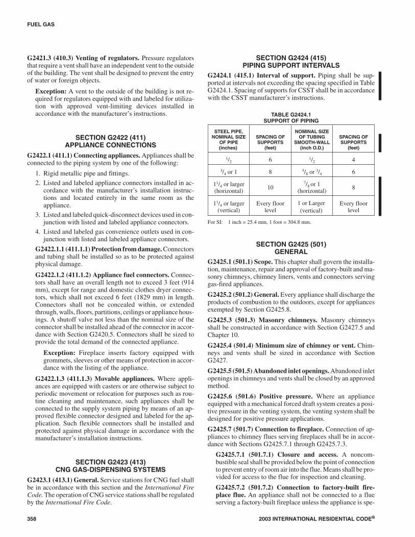
G2421.3 (410.3) Venting of regulators. Pressure regulatorsthat require a vent shall have an independent vent to the outsideof the building. The vent shall be designed to prevent the entryof water or foreign objects.
Exception: A vent to the outside of the building is not re-quired for regulators equipped with and labeled for utiliza-tion with approved vent-limiting devices installed inaccordance with the manufacturer’s instructions.
SECTION G2422 (411)APPLIANCE CONNECTIONS
G2422.1 (411.1) Connecting appliances. Appliances shall beconnected to the piping system by one of the following:
1. Rigid metallic pipe and fittings.
2. Listed and labeled appliance connectors installed in ac-cordance with the manufacturer’s installation instruc-tions and located entirely in the same room as theappliance.
3. Listed and labeled quick-disconnect devices used in con-junction with listed and labeled appliance connectors.
4. Listed and labeled gas convenience outlets used in con-junction with listed and labeled appliance connectors.
G2422.1.1 (411.1.1) Protection from damage. Connectorsand tubing shall be installed so as to be protected againstphysical damage.
G2422.1.2 (411.1.2) Appliance fuel connectors. Connec-tors shall have an overall length not to exceed 3 feet (914mm), except for range and domestic clothes dryer connec-tors, which shall not exceed 6 feet (1829 mm) in length.Connectors shall not be concealed within, or extendedthrough, walls, floors, partitions, ceilings or appliance hous-ings. A shutoff valve not less than the nominal size of theconnector shall be installed ahead of the connector in accor-dance with Section G2420.5. Connectors shall be sized toprovide the total demand of the connected appliance.
Exception: Fireplace inserts factory equipped withgrommets, sleeves or other means of protection in accor-dance with the listing of the appliance.
G2422.1.3 (411.1.3) Movable appliances. Where appli-ances are equipped with casters or are otherwise subject toperiodic movement or relocation for purposes such as rou-tine cleaning and maintenance, such appliances shall beconnected to the supply system piping by means of an ap-proved flexible connector designed and labeled for the ap-plication. Such flexible connectors shall be installed andprotected against physical damage in accordance with themanufacturer’s installation instructions.
SECTION G2423 (413)CNG GAS-DISPENSING SYSTEMS
G2423.1 (413.1) General. Service stations for CNG fuel shallbe in accordance with this section and the International FireCode. The operation of CNG service stations shall be regulatedby the International Fire Code.
SECTION G2424 (415)PIPING SUPPORT INTERVALS
G2424.1 (415.1) Interval of support. Piping shall be sup-ported at intervals not exceeding the spacing specified in TableG2424.1. Spacing of supports for CSST shall be in accordancewith the CSST manufacturer’s instructions.
TABLE G2424.1SUPPORT OF PIPING
STEEL PIPE,NOMINAL SIZE
OF PIPE(inches)
SPACING OFSUPPORTS
(feet)
NOMINAL SIZEOF TUBING
SMOOTH-WALL(inch O.D.)
SPACING OFSUPPORTS
(feet)
1/2 6 1/2 4
3/4 or 1 8 5/8 or 3/4 6
11/4 or larger(horizontal) 10
7/8 or 1(horizontal) 8
11/4 or larger(vertical)
Every floorlevel
1 or Larger(vertical)
Every floorlevel
For SI: 1 inch = 25.4 mm, 1 foot = 304.8 mm.
SECTION G2425 (501)GENERAL
G2425.1 (501.1) Scope. This chapter shall govern the installa-tion, maintenance, repair and approval of factory-built and ma-sonry chimneys, chimney liners, vents and connectors servinggas-fired appliances.
G2425.2 (501.2) General. Every appliance shall discharge theproducts of combustion to the outdoors, except for appliancesexempted by Section G2425.8.
G2425.3 (501.3) Masonry chimneys. Masonry chimneysshall be constructed in accordance with Section G2427.5 andChapter 10.
G2425.4 (501.4) Minimum size of chimney or vent. Chim-neys and vents shall be sized in accordance with SectionG2427.
G2425.5 (501.5) Abandoned inlet openings. Abandoned inletopenings in chimneys and vents shall be closed by an approvedmethod.
G2425.6 (501.6) Positive pressure. Where an applianceequipped with a mechanical forced draft system creates a posi-tive pressure in the venting system, the venting system shall bedesigned for positive pressure applications.
G2425.7 (501.7) Connection to fireplace. Connection of ap-pliances to chimney flues serving fireplaces shall be in accor-dance with Sections G2425.7.1 through G2425.7.3.
G2425.7.1 (501.7.1) Closure and access. A noncom-bustible seal shall be provided below the point of connectionto prevent entry of room air into the flue. Means shall be pro-vided for access to the flue for inspection and cleaning.
G2425.7.2 (501.7.2) Connection to factory-built fire-place flue. An appliance shall not be connected to a flueserving a factory-built fireplace unless the appliance is spe-
358 2003 INTERNATIONAL RESIDENTIAL CODE®
FUEL GAS
cifically listed for such installation. The connection shall bemade in accordance with the appliance manufacturer’s in-stallation instructions.
G2425.7.3 (501.7.3) Connection to masonry fireplaceflue. A connector shall extend from the appliance to the flueserving a masonry fireplace such that the flue gases are ex-hausted directly into the flue. The connector shall be acces-sible or removable for inspection and cleaning of both theconnector and the flue. Listed direct connection devicesshall be installed in accordance with their listing.
G2425.8 (501.8) Equipment not required to be vented. Thefollowing appliances shall not be required to be vented:
1. Ranges.
2. Built-in domestic cooking units listed and marked for op-tional venting.
3. Hot plates and laundry stoves.
4. Type 1 clothes dryers (Type 1 clothes dryers shall be ex-hausted in accordance with the requirements of SectionG2437).
5. Refrigerators.
6. Counter appliances.
7. Room heaters listed for unvented use.
Where the appliances and equipment listed in Items 5through 7 above are installed so that the aggregate input rat-ing exceeds 20 Btu per hour per cubic foot (207 watts perm3) of volume of the room or space in which such appliancesand equipment are installed, one or more shall be providedwith venting systems or other approved means for convey-ing the vent gases to the outdoor atmosphere so that the ag-gregate input rating of the remaining unvented appliancesand equipment does not exceed the 20 Btu per hour per cubicfoot (207 watts per m3) figure. Where the room or space inwhich the equipment is installed is directly connected to an-other room or space by a doorway, archway or other openingof comparable size that cannot be closed, the volume of suchadjacent room or space shall be permitted to be included inthe calculations.
G2425.9 (501.9) Chimney entrance. Connectors shall con-nect to a masonry chimney flue at a point not less than 12 inches(305 mm) above the lowest portion of the interior of the chim-ney flue.
G2425.10 (501.10) Connections to exhauster. Applianceconnections to a chimney or vent equipped with a powerexhauster shall be made on the inlet side of the exhauster. Jointson the positive pressure side of the exhauster shall be sealed toprevent flue-gas leakage as specified by the manufacturer’s in-stallation instructions for the exhauster.
G2425.11 (501.11) Masonry chimneys. Masonry chimneysutilized to vent appliances shall be located, constructed andsized as specified in the manufacturer’s installation instruc-tions for the appliances being vented and Section G2427.
G2425.12 (501.12) Residential and low-heat appliances fluelining systems. Flue lining systems for use with residen-
tial-type and low-heat appliances shall be limited to thefollowing:
1. Clay flue lining complying with the requirements ofASTM C 315 or equivalent. Clay flue lining shall be in-stalled in accordance with Chapter 10.
2. Listed chimney lining systems complying with UL 1777.
3. Other approved materials that will resist, without crack-ing, softening or corrosion, flue gases and condensate attemperatures up to 1,800°F (982°C).
G2425.13 (501.13) Category I appliance flue lining systems.Flue lining systems for use with Category I appliances shall belimited to the following:
1. Flue lining systems complying with Section G2425.12.
2. Chimney lining systems listed and labeled for use withappliances with draft hoods and other Category I gas ap-pliances listed and labeled for use with Type B vents.
G2425.14 (501.14) Category II, III and IV appliance vent-ing systems. The design, sizing and installation of vents forCategory II, III and IV appliances shall be in accordance withthe appliance manufacturer’s installation instructions.
G2425.15 (501.15) Existing chimneys and vents. Where anappliance is permanently disconnected from an existing chim-ney or vent, or where an appliance is connected to an existingchimney or vent during the process of a new installation, thechimney or vent shall comply with Sections G2425.15.1through G2425.15.4.
G2425.15.1 (501.15.1) Size. The chimney or vent shall beresized as necessary to control flue gas condensation in theinterior of the chimney or vent and to provide the applianceor appliances served with the required draft. For Category Iappliances, the resizing shall be in accordance with SectionG2426.
G2425.15.2 (501.15.2) Flue passageways. The flue gaspassageway shall be free of obstructions and combustibledeposits and shall be cleaned if previously used for venting asolid or liquid fuel-burning appliance or fireplace. The flueliner, chimney inner wall or vent inner wall shall be continu-ous and shall be free of cracks, gaps, perforations, or otherdamage or deterioration that would allow the escape of com-bustion products, including gases, moisture and creosote.
G2425.15.3 (501.15.3) Cleanout. Masonry chimney fluesshall be provided with a cleanout opening having a mini-mum height of 6 inches (152 mm). The upper edge of theopening shall be located not less than 6 inches (152 mm) be-low the lowest chimney inlet opening. The cleanout shall beprovided with a tight-fitting, noncombustible cover.
G2425.15.4 (501.15.4) Clearances. Chimneys and ventsshall have airspace clearance to combustibles in accordancewith Chapter 10 and the chimney or vent manufacturer’s in-stallation instructions. Noncombustible firestopping orfireblocking shall be provided in accordance with Chapter10.
Exception: Masonry chimneys equipped with a chim-ney lining system tested and listed for installation in
2003 INTERNATIONAL RESIDENTIAL CODE® 359
FUEL GAS

chimneys in contact with combustibles in accordancewith UL 1777, and installed in accordance with the man-ufacturer’s instructions, shall not be required to haveclearance between combustible materials and exteriorsurfaces of the masonry chimney.
SECTION G2426 (502)VENTS
G2426.1 (502.1) General. All vents, except as provided inSection G2427.7, shall be listed and labeled. Type B and BWvents shall be tested in accordance with UL 441. Type L ventsshall be tested in accordance with UL 641. Vents for CategoryII and III appliances shall be tested in accordance with UL1738. Plastic vents for Category IV appliances shall not be re-quired to be listed and labeled where such vents are as specifiedby the appliance manufacturer and are installed in accordancewith the appliance manufacturer’s installation instructions.
G2426.2 (502.2) Connectors required. Connectors shall beused to connect appliances to the vertical chimney or vent, ex-cept where the chimney or vent is attached directly to the appli-ance. Vent connector size, material, construction andinstallation shall be in accordance with Section G2427.
G2426.3 (502.3) Vent application. The application of ventsshall be in accordance with Table G2427.4.
G2426.4 (502.4) Insulation shield. Where vents pass throughinsulated assemblies, an insulation shield constructed of notless than 26 gage sheet (0.016 inch) (0.4 mm) metal shall be in-stalled to provide clearance between the vent and the insulationmaterial. The clearance shall not be less than the clearance tocombustibles specified by the vent manufacturer’s installationinstructions. Where vents pass through attic space, the shieldshall terminate not less than 2 inches (51 mm) above the insula-tion materials and shall be secured in place to prevent displace-ment. Insulation shields provided as part of a listed vent systemshall be installed in accordance with the manufacturer’s instal-lation instructions.
G2426.5 (502.5) Installation. Vent systems shall be sized, in-stalled and terminated in accordance with the vent and appli-ance manufacturer’s installation instructions and SectionG2427.
G2426.6 (502.6) Support of vents. All portions of vents shallbe adequately supported for the design and weight of the mate-rials employed.
SECTION G2427 (503)VENTING OF EQUIPMENT
G2427.1 (503.1) General. This section recognizes that thechoice of venting materials and the methods of installation ofventing systems are dependent on the operating characteristicsof the equipment being vented. The operating characteristics ofvented equipment can be categorized with respect to (1) posi-tive or negative pressure within the venting system; and (2)whether or not the equipment generates flue or vent gases thatmight condense in the venting system. See Section G2403 forthe definition of these vented appliance categories.
G2427.2 (503.2) Venting systems required. Except as permit-ted in Section G2427.2.1, Section G2427.2.2 and SectionG2425.8, all equipment shall be connected to venting systems.
G2427.2.1 (503.2.3) Direct-vent equipment. Listed di-rect-vent equipment shall be considered properly ventedwhere installed in accordance with the terms of its listing, themanufacturer’s instructions and Section G2427.8, Item 3.
G2427.2.2 (503.2.4) Equipment with integral vents.Equipment incorporating integral venting means shall beconsidered properly vented when installed in accordancewith its listing, the manufacturer’s instructions and SectionG2427.8, Items 1 and 2.
G2427.3 (503.3) Design and construction. A venting systemshall be designed and constructed so as to develop a positiveflow adequate to remove flue or vent gases to the outdoor atmo-sphere.
G2427.3.1 (503.3.1) Equipment draft requirements. Aventing system shall satisfy the draft requirements of theequipment in accordance with the manufacturer’s instruc-tions.
G2427.3.2 (503.3.2) Design and construction. Gas utiliza-tion equipment required to be vented shall be connected to aventing system designed and installed in accordance withthe provisions of Sections G2427.4 through G2427.15.
G2427.3.3 (503.3.3) Mechanical draft systems. Mechani-cal draft systems shall comply with the following:
1. Mechanical draft systems shall be listed and shall beinstalled in accordance with the terms of their listingand both the appliance and the mechanical draft sys-tem manufacturer’s instructions.
2. Equipment, except incinerators, requiring ventingshall be permitted to be vented by means of mechani-cal draft systems of either forced or induced draft de-sign.
3. Forced draft systems and all portions of induced draftsystems under positive pressure during operationshall be designed and installed so as to prevent leak-age of flue or vent gases into a building.
4. Vent connectors serving equipment vented by naturaldraft shall not be connected into any portion of me-chanical draft systems operating under positive pres-sure.
5. When a mechanical draft system is employed, provi-sion shall be made to prevent the flow of gas to themain burners when the draft system is not performingso as to satisfy the operating requirements of theequipment for safe performance.
6. The exit terminals of mechanical draft systems shallbe not less than 7 feet (2134 mm) above grade wherelocated adjacent to public walkways and shall be lo-cated as specified in Section G2427.8, Items 1 and 2.
G2427.3.4 (503.3.5) Circulating air ducts and furnaceplenums. No portion of a venting system shall extend intoor pass through any circulating air duct or furnace plenum.
360 2003 INTERNATIONAL RESIDENTIAL CODE®
FUEL GAS
➡
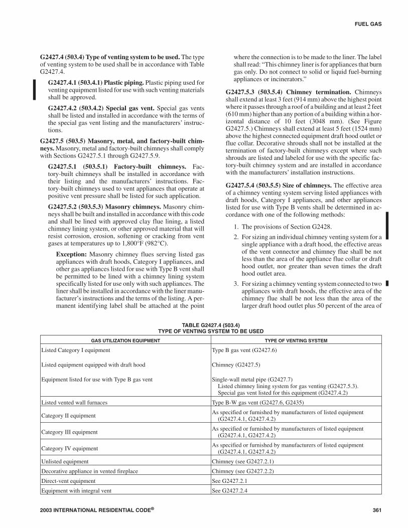
G2427.4 (503.4) Type of venting system to be used. The typeof venting system to be used shall be in accordance with TableG2427.4.
G2427.4.1 (503.4.1) Plastic piping. Plastic piping used forventing equipment listed for use with such venting materialsshall be approved.
G2427.4.2 (503.4.2) Special gas vent. Special gas ventsshall be listed and installed in accordance with the terms ofthe special gas vent listing and the manufacturers’ instruc-tions.
G2427.5 (503.5) Masonry, metal, and factory-built chim-neys. Masonry, metal and factory-built chimneys shall complywith Sections G2427.5.1 through G2427.5.9.
G2427.5.1 (503.5.1) Factory-built chimneys. Fac-tory-built chimneys shall be installed in accordance withtheir listing and the manufacturers’ instructions. Fac-tory-built chimneys used to vent appliances that operate atpositive vent pressure shall be listed for such application.
G2427.5.2 (503.5.3) Masonry chimneys. Masonry chim-neys shall be built and installed in accordance with this codeand shall be lined with approved clay flue lining, a listedchimney lining system, or other approved material that willresist corrosion, erosion, softening or cracking from ventgases at temperatures up to 1,800°F (982°C).
Exception: Masonry chimney flues serving listed gasappliances with draft hoods, Category I appliances, andother gas appliances listed for use with Type B vent shallbe permitted to be lined with a chimney lining systemspecifically listed for use only with such appliances. Theliner shall be installed in accordance with the liner manu-facturer’s instructions and the terms of the listing. A per-manent identifying label shall be attached at the point
where the connection is to be made to the liner. The labelshall read: “This chimney liner is for appliances that burngas only. Do not connect to solid or liquid fuel-burningappliances or incinerators.”
G2427.5.3 (503.5.4) Chimney termination. Chimneysshall extend at least 3 feet (914 mm) above the highest pointwhere it passes through a roof of a building and at least 2 feet(610 mm) higher than any portion of a building within a hor-izontal distance of 10 feet (3048 mm). (See FigureG2427.5.) Chimneys shall extend at least 5 feet (1524 mm)above the highest connected equipment draft hood outlet orflue collar. Decorative shrouds shall not be installed at thetermination of factory-built chimneys except where suchshrouds are listed and labeled for use with the specific fac-tory-built chimney system and are installed in accordancewith the manufacturers’ installation instructions.
G2427.5.4 (503.5.5) Size of chimneys. The effective areaof a chimney venting system serving listed appliances withdraft hoods, Category I appliances, and other applianceslisted for use with Type B vents shall be determined in ac-cordance with one of the following methods:
1. The provisions of Section G2428.
2. For sizing an individual chimney venting system for asingle appliance with a draft hood, the effective areasof the vent connector and chimney flue shall be notless than the area of the appliance flue collar or drafthood outlet, nor greater than seven times the drafthood outlet area.
3. For sizing a chimney venting system connected to twoappliances with draft hoods, the effective area of thechimney flue shall be not less than the area of thelarger draft hood outlet plus 50 percent of the area of
2003 INTERNATIONAL RESIDENTIAL CODE® 361
FUEL GAS
TABLE G2427.4 (503.4)TYPE OF VENTING SYSTEM TO BE USED
GAS UTILIZATION EQUIPMENT TYPE OF VENTING SYSTEM
Listed Category I equipment
Listed equipment equipped with draft hood
Equipment listed for use with Type B gas vent
Type B gas vent (G2427.6)
Chimney (G2427.5)
Single-wall metal pipe (G2427.7)Listed chimney lining system for gas venting (G2427.5.3).Special gas vent listed for this equipment (G2427.4.2)
Listed vented wall furnaces Type B-W gas vent (G2427.6, G2435)
Category II equipment As specified or furnished by manufacturers of listed equipment(G2427.4.1, G2427.4.2)
Category III equipment As specified or furnished by manufacturers of listed equipment(G2427.4.1, G2427.4.2)
Category IV equipment As specified or furnished by manufacturers of listed equipment(G2427.4.1, G2427.4.2)
Unlisted equipment Chimney (see G2427.2.1)
Decorative appliance in vented fireplace Chimney (see G2427.2.2)
Direct-vent equipment See G2427.2.1
Equipment with integral vent See G2427.2.4

the smaller draft hood outlet, nor greater than seventimes the smallest draft hood outlet area.
4. Chimney venting systems using mechanical draftshall be sized in accordance with approved engineer-ing methods.
5. Other approved engineering methods.G2427.5.5 (503.5.6) Inspection of chimneys. Before re-placing an existing appliance or connecting a vent connec-tor to a chimney, the chimney passageway shall beexamined to ascertain that it is clear and free of obstructionsand it shall be cleaned if previously used for venting solid orliquid fuel-burning appliances or fireplaces.
Exception: Existing chimneys shall be permitted to havetheir use continued when an appliance is replaced by anappliance of similar type, input rating and efficiency.
G2427.5.5.1 (503.5.6.1) Chimney lining. Chimneysshall be lined in accordance with Chapter 10.
G2427.5.5.2 (503.5.6.2) Cleanouts. Cleanouts shall beexamined to determine they will remain tightly closedwhen not in use.
G2427.5.5.3 (503.5.6.3) Unsafe chimneys. Where in-spection reveals that an existing chimney is not safe forthe intended application, it shall be repaired, rebuilt,lined, relined, or replaced with a vent or chimney to con-form to M1805 and Chapter 10, and it shall be suitablefor the equipment to be vented.
G2427.5.6 (503.5.7) Chimneys serving equipment burn-ing other fuels. Chimneys serving equipment burning otherfuels shall comply with Sections G2427.5.6.1 throughG2427.5.6.4.
362 2003 INTERNATIONAL RESIDENTIAL CODE®
FUEL GAS
For SI: 1 inch = 25.4 mm, 1 foot = 304.8 mm.NOTES:a. No height above parapet required when distance from walls or parapet is more than 10 feet.b. Height above any roof surface within 10 feet horizontally.
FIGURE G2427.5 (503.5)TYPICAL TERMINATION LOCATIONS FOR CHIMNEYS AND SINGLE-WALL METAL PIPES

G2427.5.6.1 (503.5.7.1) Solid fuel-burning appli-ances. Gas utilization equipment shall not be connectedto a chimney flue serving a separate appliance designedto burn solid fuel.
G2427.5.6.2 (503.5.7.2) Liquid fuel-burning appli-ances. Where one chimney flue serves gas utilizationequipment and equipment burning liquid fuel, the equip-ment shall be connected to separate openings or shall beconnected through a single opening where joined by asuitable fitting located as close as practical to the chim-ney. Where two or more openings are provided into onechimney flue, they shall be at different levels. Where thegas utilization equipment is automatically controlled, itshall be equipped with a safety shutoff device.
G2427.5.6.3 (503.5.7.3) Combination gas- and solidfuel-burning appliances. A combination gas- and solidfuel-burning appliance equipped with a manual reset de-vice to shut off gas to the main burner in the event of sus-tained backdraft or flue gas spillage shall be permitted tobe connected to a single chimney flue. The chimney flueshall be sized to properly vent the appliance.
G2427.5.6.4 (503.5.7.4) Combination gas- and oilfuel-burning appliances. A listed combination gas- andoil fuel-burning appliance shall be permitted to be con-nected to a single chimney flue. The chimney flue shallbe sized to properly vent the appliance.
G2427.5.7 (503.5.8) Support of chimneys. All portions ofchimneys shall be supported for the design and weight of thematerials employed. Factory-built chimneys shall be sup-ported and spaced in accordance with their listings and themanufacturer’s instructions.
G2427.5.8 (503.5.9) Cleanouts. Where a chimney that for-merly carried flue products from liquid or solid fuel-burningappliances is used with an appliance using fuel gas, an ac-cessible cleanout shall be provided. The cleanout shall havea tight-fitting cover and be installed so its upper edge is atleast 6 inches (152 mm) below the lower edge of the lowestchimney inlet opening.
G2427.5.9 (503.5.10) Space surrounding lining or vent.The remaining space surrounding a chimney liner, gas vent,special gas vent, or plastic piping installed within a masonrychimney flue shall not be used to vent another appliance.The insertion of another liner or vent within the chimney asprovided in this code and the liner or vent manufacturer’s in-structions shall not be prohibited.
The remaining space surrounding a chimney liner, gasvent, special gas vent, or plastic piping installed within amasonry, metal or factory-built chimney, shall not be used tosupply combustion air. Such space shall not be prohibitedfrom supplying combustion air to direct-vent appliances de-signed for installation in a solid fuel-burning fireplace andinstalled in accordance with the listing and the manufac-turer’s instructions.
G2427.6 (503.6) Gas vents. Gas vents shall comply with Sec-tions G2427.6.1 through G2427.6.10. (See Section G2403,Definitions.)
G2427.6.1 (503.6.1) Installation, general. Gas vents shallbe installed in accordance with the terms of their listings andthe manufacturer’s instructions.
G2427.6.2 (503.6.2) Type B-W vent capacity. A TypeB-W gas vent shall have a listed capacity not less than that ofthe listed vented wall furnace to which it is connected.
G2427.6.3 (503.6.3) Roof penetration. A gas vent passingthrough a roof shall extend through the roof flashing, roofjack or roof thimble and shall be terminated by a listed ter-mination cap.
G2427.6.4 (503.6.4) Offsets. Type B or Type L vents shallextend in a generally vertical direction with offsets not ex-ceeding 45 degrees (0.79 rad), except that a vent system hav-ing not more than one 60-degree offset shall be permitted.Any angle greater than 45 degrees (0.79 rad) from the verti-cal is considered horizontal. The total horizontal distance ofa vent plus the horizontal vent connector serving draft-hood-equipped appliances shall not be greater than 75 per-cent of the vertical height of the vent.
Exception: Systems designed and sized as provided inSection G2428 or in accordance with other approved en-gineering methods.
Vents serving Category I fan-assisted appliances shall beinstalled in accordance with the appliance manufacturer’sinstructions and Section G2428 or other approved engineer-ing methods.
G2427.6.5 (503.6.6) Gas vent termination. A gas ventshall terminate in accordance with one of the following:
1. Above the roof surface with a listed cap or listed roofassembly. Gas vents 12 inches (305 mm) in size orsmaller with listed caps shall be permitted to be termi-nated in accordance with Figure G2427.6.5, providedthat such vents are at least 8 feet (2438 mm) from avertical wall or similar obstruction. All other gasvents shall terminate not less than 2 feet (610 mm)above the highest point where they pass through theroof and at least 2 feet (610 mm) higher than any por-tion of a building within 10 feet (3048 mm).
2. As provided for direct-vent systems in SectionG2427.2.1.
3. As provided for equipment with integral vents in Sec-tion G2427.2.2.
4. As provided for mechanical draft systems in SectionG2427.3.3.
G2427.6.5.1 (503.6.6.1) Decorative shrouds. Decora-tive shrouds shall not be installed at the termination ofgas vents except where such shrouds are listed for usewith the specific gas venting system and are installed inaccordance with manufacturer’s installation instruc-tions.
2003 INTERNATIONAL RESIDENTIAL CODE® 363
FUEL GAS
➡
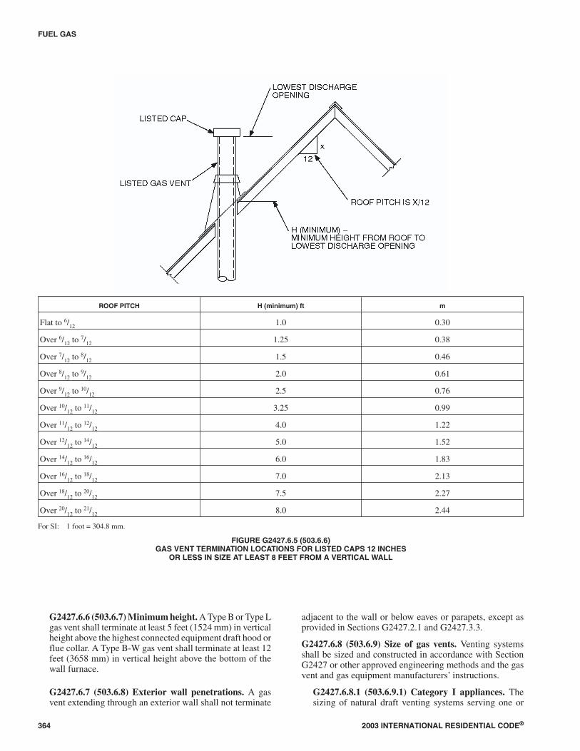
G2427.6.6 (503.6.7) Minimum height. A Type B or Type Lgas vent shall terminate at least 5 feet (1524 mm) in verticalheight above the highest connected equipment draft hood orflue collar. A Type B-W gas vent shall terminate at least 12feet (3658 mm) in vertical height above the bottom of thewall furnace.
G2427.6.7 (503.6.8) Exterior wall penetrations. A gasvent extending through an exterior wall shall not terminate
adjacent to the wall or below eaves or parapets, except asprovided in Sections G2427.2.1 and G2427.3.3.
G2427.6.8 (503.6.9) Size of gas vents. Venting systemsshall be sized and constructed in accordance with SectionG2427 or other approved engineering methods and the gasvent and gas equipment manufacturers’ instructions.
G2427.6.8.1 (503.6.9.1) Category I appliances. Thesizing of natural draft venting systems serving one or
364 2003 INTERNATIONAL RESIDENTIAL CODE®
FUEL GAS
ROOF PITCH H (minimum) ft m
Flat to 6/12 1.0 0.30
Over 6/12 to 7/12 1.25 0.38
Over 7/12 to 8/12 1.5 0.46
Over 8/12 to 9/12 2.0 0.61
Over 9/12 to 10/12 2.5 0.76
Over 10/12 to 11/12 3.25 0.99
Over 11/12 to 12/12 4.0 1.22
Over 12/12 to 14/12 5.0 1.52
Over 14/12 to 16/12 6.0 1.83
Over 16/12 to 18/12 7.0 2.13
Over 18/12 to 20/12 7.5 2.27
Over 20/12 to 21/12 8.0 2.44
For SI: 1 foot = 304.8 mm.
FIGURE G2427.6.5 (503.6.6)GAS VENT TERMINATION LOCATIONS FOR LISTED CAPS 12 INCHES
OR LESS IN SIZE AT LEAST 8 FEET FROM A VERTICAL WALL

more listed appliances equipped with a draft hood or ap-pliances listed for use with Type B gas vent, installed in asingle story of a building, shall be in accordance with oneof the following methods:
Exceptions:
1. The provisions of Section G2428.
2. For sizing an individual gas vent for a single,draft-hood-equipped appliance, the effectivearea of the vent connector and the gas vent shallbe not less than the area of the appliance drafthood outlet, nor greater than seven times thedraft hood outlet area.
3. For sizing a gas vent connected to two appli-ances with draft hoods, the effective area of thevent shall be not less than the area of the largerdraft hood outlet plus 50 percent of the area ofthe smaller draft hood outlet, nor greater thanseven times the smaller draft hood outlet area.
4. Approved engineering practices.
G2427.6.8.2 (503.6.9.2) Category II, III, and IV appli-ances. The sizing of gas vents for Category II, III and IVequipment shall be in accordance with the equipmentmanufacturer’s instructions.
G2427.6.8.3 (503.6.9.3) Mechanical draft. Chimneyventing systems using mechanical draft shall be sized inaccordance with approved engineering methods.
G2427.6.9 (503.6.11) Support of gas vents. Gas vents shallbe supported and spaced in accordance with their listingsand the manufacturers’ instructions.
G2427.6.10 (503.6.12) Marking. In those localities wheresolid and liquid fuels are used extensively, gas vents shall bepermanently identified by a label attached to the wall or ceil-ing at a point where the vent connector enters the gas vent.The determination of where such localities exist shall bemade by the code official. The label shall read:
“This gas vent is for appliances that burn gas. Do not con-nect to solid or liquid fuel-burning appliances or incinera-tors.”
G2427.7 (503.7) Single-wall metal pipe. Single-wall metalpipe vents shall comply with Sections G2427.7.1 throughG2427.7.12.
G2427.7.1 (503.7.1) Construction. Single-wall metal pipeshall be constructed of galvanized sheet steel not less than0.0304 inch (0.7 mm) thick, or other approved, noncom-bustible, corrosion-resistant material.
G2427.7.2 (503.7.2) Cold climate. Uninsulated single-wallmetal pipe shall not be used outdoors in cold climates forventing gas utilization equipment.
G2427.7.3 (503.7.3) Termination. Single-wall metal pipeshall terminate at least 5 feet (1524 mm) in vertical heightabove the highest connected equipment draft hood outlet orflue collar. Single-wall metal pipe shall extend at least 2 feet(610 mm) above the highest point where it passes through aroof of a building and at least 2 feet (610 mm) higher thanany portion of a building within a horizontal distance of 10
feet (3048 mm). (See Figure G2427.5.) An approved cap orroof assembly shall be attached to the terminus of a sin-gle-wall metal pipe. [Also see Section G2427.7.8, Item 3.]
G2427.7.4 (503.7.4) Limitations of use. Single-wall metalpipe shall be used only for runs directly from the space inwhich the equipment is located through the roof or exteriorwall to the outdoor atmosphere.
G2427.7.5 (503.7.5) Roof penetrations. A pipe passingthrough a roof shall extend without interruption through theroof flashing, roof jacket or roof thimble. Where a sin-gle-wall metal pipe passes through a roof constructed ofcombustible material, a noncombustible, nonventilatingthimble shall be used at the point of passage. The thimbleshall extend at least 18 inches (457 mm) above and 6 inches(152 mm) below the roof with the annular space open at thebottom and closed only at the top. The thimble shall be sizedin accordance with Section G2427.10.15.
G2427.7.6 (503.7.6) Installation. Single-wall metal pipeshall not originate in any unoccupied attic or concealedspace and shall not pass through any attic, inside wall, con-cealed space or floor. The installation of a single-wall metalpipe through an exterior combustible wall shall comply withSection G2427.10.15.
G2427.7.7 (503.7.7) Clearances. Minimum clearancesfrom single-wall metal pipe to combustible material shall bein accordance with Table G2427.7.7. The clearance fromsingle-wall metal pipe to combustible material shall be per-mitted to be reduced where the combustible material is pro-tected as specified for vent connectors in Table G2409.2.
G2427.7.8 (503.7.8) Size of single-wall metal pipe. Aventing system constructed of single-wall metal pipe shallbe sized in accordance with one of the following methodsand the equipment manufacturer’s instructions:
1. For a draft hood-equipped appliance, in accordancewith Section G2428.
2. For a venting system for a single appliance with adraft hood, the areas of the connector and the pipeeach shall not be less than the area of the applianceflue collar or draft hood outlet, whichever is smaller.The vent area shall not be greater than seven times thedraft hood outlet area.
3. Other approved engineering methods.
G2427.7.9 (503.7.9) Pipe geometry. Any shaped sin-gle-wall metal pipe shall be permitted to be used, providedits equivalent effective area is equal to the effective area ofthe round pipe for which it is substituted and provided theminimum internal dimension of the pipe is not less than 2inches (51 mm).
G2427.7.10 (503.7.10) Termination capacity. The ventcap or a roof assembly shall have a venting capacity not lessthan that of the pipe to which it is attached.
G2427.7.11 (503.7.11) Support of single-wall metal pipe.All portions of single-wall metal pipe shall be supported forthe design and weight of the material employed.
2003 INTERNATIONAL RESIDENTIAL CODE® 365
FUEL GAS

G2427.7.12 (503.7.12) Marking. Single-wall metal pipeshall comply with the marking provisions of SectionG2427.6.10.
G2427.8 (503.8) Venting system termination location. Thelocation of venting system terminations shall comply with thefollowing (see Appendix C):
1. A mechanical draft venting system shall terminate atleast 3 feet (914 mm) above any forced-air inlet locatedwithin 10 feet (3048 mm).
Exceptions:
1. This provision shall not apply to the combus-tion air intake of a direct-vent appliance.
2. This provision shall not apply to the separationof the integral outdoor air inlet and flue gas dis-charge of listed outdoor appliances.
2. A mechanical draft venting system, excluding di-rect-vent appliances, shall terminate at least 4 feet (1219mm) below, 4 feet (1219 mm) horizontally from, or 1foot (305 mm) above any door, operable window, orgravity air inlet into any building. The bottom of the ventterminal shall be located at least 12 inches (305 mm)above grade.
3. The vent terminal of a direct-vent appliance with an inputof 10,000 Btu per hour (3 kW) or less shall be located atleast 6 inches (152 mm) from any air opening into abuilding, and such an appliance with an input over10,000 Btu per hour (3 kW) but not over 50,000 Btu perhour (14.7 kW) shall be installed with a 9-inch (230 mm)vent termination clearance, and an appliance with an in-put over 50,000 Btu/h (14.7 kw) shall have at least a12-inch (305 mm) vent termination clearance. The bot-tom of the vent terminal and the air intake shall be locatedat least 12 inches (305 mm) above grade.
4. Through-the-wall vents for Category II and IV appli-ances and noncategorized condensing appliances shallnot terminate over public walkways or over an areawhere condensate or vapor could create a nuisance orhazard or could be detrimental to the operation of regula-
tors, relief valves, or other equipment. Where local expe-rience indicates that condensate is a problem with Cate-gory I and III appliances, this provision shall also apply.
G2427.9 (503.9) Condensation drainage. Provision shall bemade to collect and dispose of condensate from venting sys-tems serving Category II and IV equipment and noncategorizedcondensing appliances in accordance with Section G2427.8,Item 4. Where local experience indicates that condensation is aproblem, provision shall be made to drain off and dispose ofcondensate from venting systems serving Category I and IIIequipment in accordance with Section G2427.8, Item 4.
G2427.10 (503.10) Vent connectors for Category I gas utili-zation equipment. Vent connectors for Category I equipmentshall comply with Sections G2427.10.1 through G2427.10.15.
G2427.10.1 (503.10.1) Where required. A vent connectorshall be used to connect equipment to a gas vent, chimney orsingle-wall metal pipe, except where the gas vent, chimneyor single-wall metal pipe is directly connected to the equip-ment.
G2427.10.2 (503.10.2) Materials. Vent connectors shall beconstructed in accordance with Sections G2427.10.2.1through G2427.10.2.4.
G2427.10.2.1 (503.10.2.1) General. A vent connectorshall be made of noncombustible corrosion-resistant ma-terial capable of withstanding the vent gas temperatureproduced by the equipment and of sufficient thickness towithstand physical damage.
G2427.10.2.2 (503.10.2.2) Vent connectors located inunconditioned areas. Where the vent connector used forequipment having a draft hood or a Category I applianceis located in or passes through attics, crawl spaces orother unconditioned spaces, that portion of the vent con-nector shall be listed Type B or Type L or listed vent ma-terial or listed material having equivalent insulationproperties.
Exception: Single-wall metal pipe located within theexterior walls of the building in areas having a local99-percent winter design temperature of 5°F (-15°C)
366 2003 INTERNATIONAL RESIDENTIAL CODE®
FUEL GAS
TABLE G2427.7.7 (503.7.7)CLEARANCES FOR CONNECTORS
MINIMUM DISTANCE FROM COMBUSTIBLE MATERIAL
EquipmentListed Type B gas
vent materialListed Type Lvent material
Single-wallmetal pipe
Factory-builtchimney sections
Listed equipment with draft hoods and equipmentlisted for use with Type B Gas Vents as listed as listed 6 inches as listed
Residential boilers and furnaces with listed gasconversion burner and with draft hood 6 inches 6 inches 9 inches as listed
Residential appliances listed for use with Type Lvents not permitted as listed 9 inches as listed
Unlisted residential appliances with draft hood not permitted 6 inches 9 inches as listed
Residential and low-heat equipment other thanthose above not permitted 9 inches 18 inches as listed
For SI: 1 inch = 25.4 mm.NOTE: These clearances shall apply unless the listing of an appliance or connector specifies different clearances, in which case the listed clearances shall apply.

or higher shall be permitted to be used in uncondi-tioned spaces other than attics and crawl spaces.
G2427.10.2.3 (503.10.2.3) Residential-type applianceconnectors. Where vent connectors for residential-typeappliances are not installed in attics or other uncondi-tioned spaces, connectors for listed appliances havingdraft hoods and for appliances having draft hoods andequipped with listed conversion burners shall be one ofthe following:
1. Type B or Type L vent material;
2. Galvanized sheet steel not less than 0.018 inch(0.46 mm) thick;
3. Aluminum (1100 or 3003 alloy or equivalent)sheet not less than 0.027 inch (0.69 mm) thick;
4. Stainless steel sheet not less than 0.012 inch (0.31mm) thick;
5. Smooth interior wall metal pipe having resistanceto heat and corrosion equal to or greater than that ofItem 2, 3 or 4 above; or
6. A listed vent connector.
G2427.10.2.4 (503.10.2.4) Low-heat equipment. Avent connector for low-heat equipment shall be a fac-tory-built chimney section or steel pipe having resistanceto heat and corrosion equivalent to that for the appropri-ate galvanized pipe as specified in Table G2427.10.2.4.Factory-built chimney sections shall be joined togetherin accordance with the chimney manufacturers’ instruc-tions.
TABLE G2427.10.2.4 (503.10.2.4)MINIMUM THICKNESS FOR GALVANIZED STEEL VENT
CONNECTORS FOR LOW-HEAT APPLIANCES
DIAMETER OF CONNECTOR(inches)
MINIMUM THICKNESS(inch)
Less than 6 0.019
6 to less than 10 0.023
10 to 12 inclusive 0.029
14 to 16 inclusive 0.034
Over 16 0.056
For SI: 1 inch = 25.4 mm, 1 square inch = 645.16 mm2.
G2427.10.3 (503.10.3) Size of vent connector. Vent con-nectors shall be sized in accordance with SectionsG2427.10.3.1 through G2427.10.3.5.
G2427.10.3.1 (503.10.3.1) Single draft hood and fanassisted. A vent connector for equipment with a singledraft hood or for a Category I fan-assisted combustionsystem appliance shall be sized and installed inaccordance with Section G2428 or other approved engi-neering methods.
G2427.10.3.2 (503.10.3.2) Multiple draft hood. For asingle appliance having more than one draft hood outletor flue collar, the manifold shall be constructed accord-ing to the instructions of the appliance manufacturer. Ifthere are no instructions, the manifold shall be designed
and constructed in accordance with approved engineer-ing practices. As an alternate method, the effective areaof the manifold shall equal the combined area of the fluecollars or draft hood outlets and the vent connectors shallhave a minimum 1 foot (305 mm) rise.
G2427.10.3.3 (503.10.3.3) Multiple appliances. Wheretwo or more appliances are connected to a common ventor chimney, each vent connector shall be sized in accor-dance with Section G2428 or other approved engineeringmethods.
As an alternative method applicable only where all ofthe appliances are draft hood equipped, each vent con-nector shall have an effective area not less than the area ofthe draft hood outlet of the appliance to which it isconnected.
G2427.10.3.4 (503.10.3.4) Common connector/mani-fold. Where two or more gas appliances are ventedthrough a common vent connector or vent manifold, thecommon vent connector or vent manifold shall be lo-cated at the highest level consistent with available head-room and the required clearance to combustiblematerials and shall be sized in accordance with SectionG2428 or other approved engineering methods.
As an alternate method applicable only where thereare two draft-hood-equipped appliances, the effectivearea of the common vent connector or vent manifold andall junction fittings shall be not less than the area of thelarger vent connector plus 50 percent of the area of thesmaller flue collar outlet.
G2427.10.3.5 (503.10.3.5) Size increase. Where thesize of a vent connector is increased to overcome installa-tion limitations and obtain connector capacity equal tothe equipment input, the size increase shall be made atthe equipment draft hood outlet.
G2427.10.4 (503.10.4) Two or more appliances con-nected to a single vent. Where two or more vent connectorsenter a common gas vent, chimney flue or single-wall metalpipe, the smaller connector shall enter at the highest levelconsistent with the available headroom or clearance to com-bustible material. Vent connectors serving Category I appli-ances shall not be connected to any portion of a mechanicaldraft system operating under positive static pressure, suchas those serving Category III or IV appliances.
G2427.10.5 (503.10.5) Clearance. Minimum clearancesfrom vent connectors to combustible material shall be in ac-cordance with Table G2427.7.7.
Exception: The clearance between a vent connector andcombustible material shall be permitted to be reducedwhere the combustible material is protected as specifiedfor vent connectors in Table G2409.2.
G2427.10.6 (503.10.6) Flow resistance. A vent connectorshall be installed so as to avoid turns or other constructionfeatures that create excessive resistance to flow of ventgases.
2003 INTERNATIONAL RESIDENTIAL CODE® 367
FUEL GAS
➡

G2427.10.7 (503.10.7) Joints. Joints between sections ofconnector piping and connections to flue collars and hoodoutlets shall be fastened by one of the following methods:
1. Sheet metal screws.
2. Vent connectors of listed vent material assembled andconnected to flue collars or draft hood outlets in ac-cordance with the manufacturers’ instructions.
3. Other approved means.
G2427.10.8 (503.10.8) Slope. A vent connector shall be in-stalled without dips or sags and shall slope upward towardthe vent or chimney at least 1/4 inch per foot (21 mm/m).
Exception: Vent connectors attached to a mechanicaldraft system installed in accordance with the manufac-turer’s instructions.
G2427.10.9 (503.10.9) Length of vent connector. A ventconnector shall be as short as practical and the equipmentlocated as close as practical to the chimney or vent. Exceptas provided for in Section G2427.10.3, the maximum hori-zontal length of a single-wall connector shall be 75 percentof the height of the chimney or vent. Except as provided forin Section G2427.10.3, the maximum horizontal length of aType B double-wall connector shall be 100 percent of theheight of the chimney or vent. For a chimney or vent systemserving multiple appliances, the maximum length of an indi-vidual connector, from the appliance outlet to the junctionwith the common vent or another connector, shall be 100percent of the height of the chimney or vent.
G2427.10.10 (503.10.10) Support. A vent connector shallbe supported for the design and weight of the material em-ployed to maintain clearances and prevent physical damageand separation of joints.
G2427.10.11 (503.10.11) Chimney connection. Whereentering a flue in a masonry or metal chimney, the vent con-nector shall be installed above the extreme bottom to avoidstoppage. A thimble or slip joint shall be permitted to beused to facilitate removal of the connector. The connectorshall be firmly attached to or inserted into the thimble or slipjoint to prevent the connector from falling out. Means shallbe employed to prevent the connector from entering so far asto restrict the space between its end and the opposite wall ofthe chimney flue. (See Section G2425.9.)
G2427.10.12 (503.10.12) Inspection. The entire length of avent connector shall be provided with ready access for in-spection, cleaning and replacement.
G2427.10.13 (503.10.13) Fireplaces. A vent connectorshall not be connected to a chimney flue serving a fireplaceunless the fireplace flue opening is permanently sealed.
G2427.10.14 (503.10.14) Passage through ceilings, floorsor walls. A vent connector shall not pass through any ceil-ing, floor or fire-resistance-rated wall. A single-wall metalpipe connector shall not pass through any interior wall.
Exception: Vent connectors made of listed Type B orType L vent material and serving listed equipment withdraft hoods and other equipment listed for use with TypeB gas vents shall be permitted to pass through walls orpartitions constructed of combustible material if the con-
nectors are installed with not less than the listedclearance to combustible material.
G2427.10.15 (503.10.15) Single-wall connector penetra-tions of combustible walls. A vent connector made of a sin-gle-wall metal pipe shall not pass through a combustibleexterior wall unless guarded at the point of passage by a ven-tilated metal thimble not smaller than the following:
1. For listed appliances equipped with draft hoods andappliances listed for use with Type B gas vents, thethimble shall be not less than 4 inches (102 mm) largerin diameter than the vent connector. Where there is arun of not less than 6 feet (1829 mm) of vent connectorin the open between the draft hood outlet and the thim-ble, the thimble shall be permitted to be 2 inches (51mm) larger in diameter than the vent connector.
2. For unlisted appliances having draft hoods, the thim-ble shall be not less than 6 inches (152 mm) larger indiameter than the vent connector.
3. For residential appliances and low-heat appliances,the thimble shall be not less than 12 inches (305 mm)larger in diameter than the vent connector.
Exception: In lieu of thimble protection, all com-bustible material in the wall shall be removed fromthe vent connector a sufficient distance to providethe specified clearance from such vent connectorto combustible material. Any material used toclose up such opening shall be noncombustible.
G2427.11 (503.11) Vent connectors for Category II, III andIV appliances. Vent connectors for Category II, III and IV ap-pliances shall be as specified for the venting system in accor-dance with Section G2427.4.
G2427.12 (503.12) Draft hoods and draft controls. The in-stallation of draft hoods and draft controls shall comply withSections G2427.12.1 through G2427.12.7.
G2427.12.1 (503.12.1) Equipment requiring draft hoods.Vented equipment shall be installed with draft hoods.
Exception: Dual-oven type combination ranges; incin-erators; direct-vent equipment; fan-assisted combustionsystem appliances; equipment requiring chimney draftfor operation; single firebox boilers equipped with con-version burners with inputs greater than 400,000 Btu perhour (117 kw); equipment equipped with blast, power orpressure burners that are not listed for use with drafthoods; and equipment designed for forced venting.
G2427.12.2 (503.12.2) Installation. A draft hood suppliedwith or forming a part of listed vented equipment shall be in-stalled without alteration, exactly as furnished and specifiedby the equipment manufacturer.
G2427.12.2.1 (503.12.2.1) Draft hood required. If adraft hood is not supplied by the equipment manufacturerwhere one is required, a draft hood shall be installed,shall be of a listed or approved type and, in the absence ofother instructions, shall be of the same size as the equip-ment flue collar. Where a draft hood is required with aconversion burner, it shall be of a listed or approved type.
368 2003 INTERNATIONAL RESIDENTIAL CODE®
FUEL GAS
➡

G2427.12.2.2 (503.12.2.2) Special design draft hood.Where it is determined that a draft hood of special designis needed or preferable for a particular installation, the in-stallation shall be in accordance with the recommenda-tions of the equipment manufacturer and shall beapproved.
G2427.12.3 (503.12.3) Draft control devices. Where adraft control device is part of the equipment or is supplied bythe equipment manufacturer, it shall be installed in accor-dance with the manufacturer’s instructions. In the absenceof manufacturers’ instructions, the device shall be attachedto the flue collar of the equipment or as near to the equip-ment as practical.
G2427.12.4 (503.12.4) Additional devices. Equipment re-quiring controlled chimney draft shall be permitted to beequipped with a listed double acting barometric draft regu-lator installed and adjusted in accordance with the manufac-turer’s instructions.
G2427.12.5 (503.12.6) Location. Draft hoods and draftregulators shall be installed in the same room or enclosure asthe equipment in such a manner as to prevent any differencein pressure between the hood or regulator and the combus-tion air supply.
G2427.12.6 (503.12.7) Positioning. Draft hoods and draftregulators shall be installed in the position for which theywere designed with reference to the horizontal and verticalplanes and shall be located so that the relief opening is notobstructed by any part of the equipment or adjacent con-struction. The equipment and its draft hood shall be locatedso that the relief opening is accessible for checking vent op-eration.
G2427.12.7 (503.12.8) Clearance. A draft hood shall be lo-cated so its relief opening is not less than 6 inches (152 mm)from any surface except that of the equipment it serves andthe venting system to which the draft hood is connected.Where a greater or lesser clearance is indicated on the equip-ment label, the clearance shall be not less than that specifiedon the label. Such clearances shall not be reduced.
G2427.13 (503.13) Manually operated dampers. A manu-ally operated damper shall not be placed in the vent connectorfor any equipment. Fixed baffles shall not be classified as man-ually operated dampers.
G2427.14 (503.14) Automatically operated vent dampers.An automatically operated vent damper shall be of a listed type.
G2427.15 (503.15) Obstructions. Devices that retard the flowof vent gases shall not be installed in a vent connector, chimney,or vent. The following shall not be considered as obstructions:
1. Draft regulators and safety controls specifically listed forinstallation in venting systems and installed in accor-dance with the terms of their listing.
2. Approved draft regulators and safety controls that are de-signed and installed in accordance with approved engi-neering methods.
3. Listed heat reclaimers and automatically operated ventdampers installed in accordance with the terms of theirlisting.
4. Approved economizers, heat reclaimers, and recupera-tors installed in venting systems of equipment not re-quired to be equipped with draft hoods, provided that thegas utilization equipment manufacturer’s instructionscover the installation of such a device in the venting sys-tem and performance in accordance with SectionsG2427.3 and G2427.3.1 is obtained.
5. Vent dampers serving listed appliances installed in ac-cordance with Sections G2428.2.1 and G2428.3.1 orother approved engineering methods.
SECTION G2428 (504)SIZING OF CATEGORY I APPLIANCE
VENTING SYSTEMSG2428.1 (504.1) Definitions. The following definitions applyto tables in this section.
APPLIANCE CATEGORIZED VENT DIAME-TER/AREA. The minimum vent area/diameter permissiblefor Category I appliances to maintain a nonpositive vent staticpressure when tested in accordance with nationally recognizedstandards.
FAN-ASSISTED COMBUSTION SYSTEM. An applianceequipped with an integral mechanical means to either draw orforce products of combustion through the combustion chamberor heat exchanger.
FAN MIN. The minimum input rating of a Category I fan-as-sisted appliance attached to a vent or connector.
FAN MAX. The maximum input rating of a Category I fan-as-sisted appliance attached to a vent or connector.
NAT MAX. The maximum input rating of a Category Idraft-hood-equipped appliance attached to a vent or connector.
FAN + FAN. The maximum combined appliance input ratingof two or more Category I fan-assisted appliances attached tothe common vent.
FAN + NAT. The maximum combined appliance input ratingof one or more Category I fan-assisted appliances and one ormore Category I draft-hood-equipped appliances attached tothe common vent.
NA. Vent configuration is not permitted due to potential forcondensate formation or pressurization of the venting system,or not applicable due to physical or geometric restraints.
NAT + NAT. The maximum combined appliance input ratingof two or more Category I draft-hood-equipped appliances at-tached to the common vent.
G2428.2 (504.2) Application of single appliance vent TablesG2428.2(1) and G2428.2(2). The application of TablesG2428.2(1) and G2428.2(2) shall be subject to the require-ments of Sections G2428.2.1 through G2428.2.13.
2003 INTERNATIONAL RESIDENTIAL CODE® 369
FUEL GAS
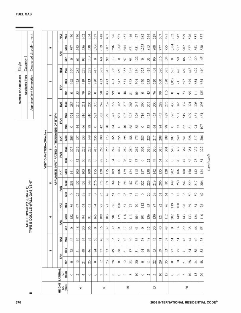
370 2003 INTERNATIONAL RESIDENTIAL CODE®
FUEL GAS
HE
IGH
T(H
)(f
eet)
LA
TE
RA
L(L
)(f
eet)
VE
NT
DIA
ME
TE
R—
(D)
inch
es
34
56
78
9
AP
PL
IAN
CE
INP
UT
RA
TIN
GIN
TH
OU
SA
ND
SO
FB
TU
/H
FAN
NA
TFA
NN
AT
FAN
NA
TFA
NN
AT
FAN
NA
TFA
NN
AT
FAN
NA
T
Min
Max
Max
Min
Max
Max
Min
Max
Max
Min
Max
Max
Min
Max
Max
Min
Max
Max
Min
Max
Max
6
00
7846
015
286
025
114
10
375
205
052
428
50
698
370
089
747
0
213
5136
1897
6727
157
105
3223
215
744
321
217
5342
528
563
543
370
421
4934
3094
6439
153
103
5022
715
366
316
211
7941
927
993
536
362
625
4632
3691
6147
149
100
5922
314
978
310
205
9341
327
311
053
035
4
8
00
8450
016
594
027
615
50
415
235
058
332
00
780
415
01,
006
537
212
5740
1610
975
2517
812
028
263
180
4236
524
750
483
322
6061
941
8
523
5338
3210
371
4217
111
553
255
173
7035
623
783
473
313
9960
740
7
828
4935
3998
6651
164
109
6424
716
584
347
227
9946
330
311
759
639
6
10
00
8853
017
510
00
295
166
044
725
50
631
345
084
745
00
1,09
658
5
212
6142
1711
881
2319
412
926
289
195
4040
227
348
533
355
5768
445
7
523
5740
3211
377
4118
712
452
280
188
6839
226
381
522
346
9567
144
6
1030
5136
4110
470
5417
611
567
267
175
8837
624
510
450
433
012
265
142
7
15
00
9458
019
111
20
327
187
050
228
50
716
390
097
052
50
1,26
368
2
211
6948
1513
693
2022
615
022
339
225
3847
531
645
633
414
5381
554
4
522
6545
3013
087
3921
914
249
330
217
6446
330
076
620
403
9080
052
9
1029
5941
4012
182
5120
613
564
315
208
8444
528
899
600
386
116
777
507
1535
5337
4811
276
6119
512
876
301
198
9842
927
511
558
037
313
475
549
1
20
00
9761
020
211
90
349
202
054
030
70
776
430
01,
057
575
01,
384
752
210
7551
1414
910
018
250
166
2037
724
933
531
346
4171
147
050
917
612
521
7148
2914
396
3824
216
047
367
241
6251
933
773
697
460
8690
259
9
1028
6444
3813
389
5022
915
062
351
228
8149
932
195
675
443
112
877
576
1534
5840
4612
484
5921
714
273
337
217
9448
130
811
165
442
712
985
355
7
2048
5235
5511
678
6920
613
484
322
206
107
464
295
125
634
410
145
830
537
(con
tinu
ed)
TAB
LE
G24
28.2
(1)
[504
.2(1
)]T
YP
EB
DO
UB
LE
-WA
LL
GA
SV
EN
T
Nu
mb
ero
fA
pp
lian
ces
Sing
le
Ap
plia
nce
Typ
eC
ateg
ory
I
Ap
plia
nce
Ven
tC
on
nec
tio
nC
onne
cted
dire
ctly
tove
nt

2003 INTERNATIONAL RESIDENTIAL CODE® 371
FUEL GAS
HE
IGH
T(H
)(f
eet)
LA
TE
RA
L(L
)(f
eet)
VE
NT
DIA
ME
TE
R—
(D)
inch
es
34
56
78
9
AP
PL
IAN
CE
INP
UT
RA
TIN
GIN
TH
OU
SA
ND
SO
FB
TU
/H
FAN
NA
TFA
NN
AT
FAN
NA
TFA
NN
AT
FAN
NA
TFA
NN
AT
FAN
NA
T
Min
Max
Max
Min
Max
Max
Min
Max
Max
Min
Max
Max
Min
Max
Max
Min
Max
Max
Min
Max
Max
30
00
100
640
213
128
037
422
00
587
336
085
347
50
1,17
365
00
1,54
885
5
29
8156
1316
611
214
283
185
1843
228
027
613
394
3382
653
542
1,07
270
0
521
7754
2816
010
836
275
176
4542
127
358
600
385
6981
152
482
1,05
568
8
1027
7050
3715
010
248
262
171
5940
526
177
580
371
9178
850
710
71,
028
668
1533
64N
A44
141
9657
249
163
7038
924
990
560
357
105
765
490
124
1,00
264
8
2056
58N
A53
132
9066
237
154
8037
423
710
254
234
311
974
347
313
997
762
8
30N
AN
AN
A73
113
NA
8821
4N
A10
434
621
913
150
732
114
970
244
417
192
959
4
50
00
101
670
216
134
039
723
20
633
363
093
251
80
1,29
770
80
1,73
095
2
28
8661
1118
312
214
320
206
1549
731
422
715
445
2697
561
533
1,27
681
3
520
82N
A27
177
119
3531
220
043
487
308
5570
243
865
960
605
771,
259
798
1026
76N
A35
168
114
4529
919
056
471
298
7368
142
686
935
589
101
1,23
077
3
1559
70N
A42
158
NA
5428
718
066
455
288
8566
241
310
091
157
211
71,
203
747
20N
AN
AN
A50
149
NA
6327
516
976
440
278
9764
240
111
388
855
613
11,
176
722
30N
AN
AN
A69
131
NA
8425
0N
A99
410
259
123
605
376
141
844
522
161
1,12
567
0
For
SI:
1in
ch=
25.4
mm
,1fo
ot=
304.
8m
m,1
Bri
tish
ther
mal
unit
per
hour
=0.
2931
W.
TAB
LE
G24
28.2
(1)
[504
.2(1
)]—
con
tin
ued
TY
PE
BD
OU
BL
E-W
AL
LG
AS
VE
NT
Nu
mb
ero
fA
pp
lian
ces
Sing
le
Ap
plia
nce
Typ
eC
ateg
ory
I
Ap
plia
nce
Ven
tC
on
nec
tio
nC
onne
cted
dire
ctly
tove
nt
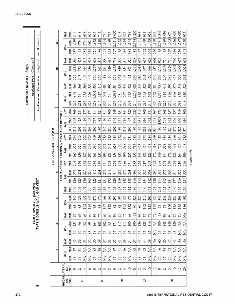
372 2003 INTERNATIONAL RESIDENTIAL CODE®
FUEL GAS
HE
IGH
T(H
)(f
eet)
LA
TE
RA
L(L
)(f
eet)
VE
NT
DIA
ME
TE
R—
(D)
inch
es
34
56
78
910
12
AP
PL
IAN
CE
INP
UT
RA
TIN
GIN
TH
OU
SA
ND
SO
FB
TU
/H
FAN
NA
TFA
NN
AT
FAN
NA
TFA
NN
AT
FAN
NA
TFA
NN
AT
FAN
NA
TFA
NN
AT
FAN
NA
T
Min
Max
Max
Min
Max
Max
Min
Max
Max
Min
Max
Max
Min
Max
Max
Min
Max
Max
Min
Max
Max
Min
Max
Max
Min
Max
Max
6
038
7745
5915
185
8524
914
012
637
320
416
552
228
421
169
536
926
789
446
937
11,
118
569
537
1,63
984
9
239
5136
6096
6685
156
104
123
231
156
159
320
213
201
423
284
251
541
368
347
673
453
498
979
648
4N
AN
A33
7492
6310
215
210
214
622
515
218
731
320
823
741
627
729
553
336
040
966
444
358
497
163
8
6N
AN
A31
8389
6011
414
799
163
220
148
207
307
203
263
409
271
327
526
352
449
656
433
638
962
627
8
037
8350
5816
493
8327
315
412
341
223
416
158
031
920
677
741
425
81,
002
536
360
1,25
765
852
11,
852
967
239
5639
5910
875
8317
611
912
126
117
915
536
324
619
748
232
124
661
741
733
976
851
348
61,
120
743
5N
AN
A37
7710
269
107
168
114
151
252
171
193
352
235
245
470
311
305
604
404
418
754
500
598
1,10
473
0
8N
AN
A33
9095
6412
216
110
717
524
316
322
334
222
528
045
830
034
459
139
247
074
048
666
51,
089
715
10
037
8753
5717
499
8229
316
512
044
425
415
862
834
420
284
444
925
31,
093
584
351
1,37
371
850
72,
031
1,05
7
239
6141
5911
780
8219
312
811
928
719
415
340
027
219
353
135
424
268
145
633
284
955
947
51,
242
848
552
5639
7611
176
105
185
122
148
277
186
190
388
261
241
518
344
299
667
443
409
834
544
584
1,22
482
5
10N
AN
A34
9710
068
132
171
112
188
261
171
237
369
241
296
497
325
363
643
423
492
808
520
688
1,19
478
8
15
036
9357
5619
011
180
325
186
116
499
283
153
713
388
195
966
523
244
1,25
968
133
61,
591
838
488
2,37
41,
237
238
6947
5713
693
8022
514
911
533
722
414
847
331
418
763
141
323
281
254
331
91,
015
673
457
1,49
198
3
551
6344
7512
886
102
216
140
144
326
217
182
459
298
231
616
400
287
795
526
392
997
657
562
1,46
996
3
10N
AN
A39
9511
679
128
201
131
182
308
203
228
438
284
284
592
381
349
768
501
470
966
628
664
1,43
392
8
15N
AN
AN
AN
AN
A72
158
186
124
220
290
192
272
418
269
334
568
367
404
742
484
540
937
601
750
1,39
989
4
20
035
9660
5420
011
878
346
201
114
537
306
149
772
428
190
1,05
357
323
81,
379
750
326
1,75
192
747
32,
631
1,34
6
237
7450
5614
899
7824
816
511
337
524
814
452
834
418
270
846
822
791
461
130
91,
146
754
443
1,68
91,
098
550
6847
7314
094
100
239
158
141
363
239
178
514
334
224
692
457
279
896
596
381
1,12
673
454
71,
665
1,07
4
10N
AN
A41
9312
986
125
223
146
177
344
224
222
491
316
277
666
437
339
866
570
457
1,09
270
264
61,
626
1,03
7
15N
AN
AN
AN
AN
A80
155
208
136
216
325
210
264
469
301
325
640
419
393
838
549
526
1,06
067
773
01,
587
1,00
5
20N
AN
AN
AN
AN
AN
A18
619
212
625
430
619
630
944
828
537
461
640
044
881
052
659
21,
028
651
808
1,55
097
3
(con
tinu
ed)
TA
BL
EG
2428
.2(2
)[5
04.2
(2)]
TY
PE
BD
OU
BL
E-W
AL
LG
AS
VE
NT
Nu
mb
ero
fA
pp
lian
ces
Sing
le
Ap
plia
nce
Typ
eC
ateg
ory
I
Ap
plia
nce
Ven
tC
on
nec
tio
nSi
ngle
-wal
lmet
alco
nnec
tor
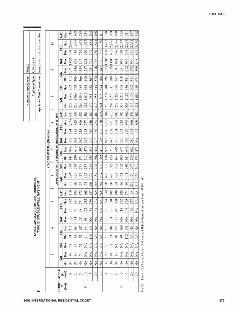
2003 INTERNATIONAL RESIDENTIAL CODE® 373
FUEL GAS
HE
IGH
T(H
)(f
eet)
LA
TE
RA
L(L
)(f
eet)
VE
NT
DIA
ME
TE
R—
(D)
inch
es
34
56
78
910
12
AP
PL
IAN
CE
INP
UT
RA
TIN
GIN
TH
OU
SA
ND
SO
FB
TU
/H
FAN
NA
TFA
NN
AT
FAN
NA
TFA
NN
AT
FAN
NA
TFA
NN
AT
FAN
NA
TFA
NN
AT
FAN
NA
T
Min
Max
Max
Min
Max
Max
Min
Max
Max
Min
Max
Max
Min
Max
Max
Min
Max
Max
Min
Max
Max
Min
Max
Max
Min
Max
Max
30
034
9963
5321
112
776
372
219
110
584
334
144
849
472
184
1,16
864
722
91,
542
852
312
1,97
11,
056
454
2,99
61,
545
237
8056
5516
411
176
281
183
109
429
279
139
610
392
175
823
533
219
1,06
969
829
61,
346
863
424
1,99
91,
308
549
7452
7215
710
698
271
173
136
417
271
171
595
382
215
806
521
269
1,04
968
436
61,
324
846
524
1,97
11,
283
10N
AN
AN
A91
144
9812
225
516
817
139
725
721
357
036
726
577
750
132
71,
017
662
440
1,28
782
162
01,
927
1,23
4
15N
AN
AN
A11
513
1N
A15
123
915
720
837
724
225
554
734
931
275
048
137
998
563
850
71,
251
794
702
1,88
41,
205
20N
AN
AN
AN
AN
AN
A18
122
3N
A24
635
722
829
852
433
336
072
346
143
395
561
557
01,
216
768
780
1,84
11,
166
30N
AN
AN
AN
AN
AN
AN
AN
AN
AN
AN
AN
A38
947
730
546
167
042
654
189
557
470
41,
147
720
937
1,75
91,
101
50
033
9966
5121
313
373
394
230
105
629
361
138
928
515
176
1,29
270
422
01,
724
948
295
2,22
31,
189
428
3,43
21,
818
236
8461
5318
112
173
318
205
104
495
312
133
712
443
168
971
613
209
1,27
381
128
01,
615
1,00
740
12,
426
1,50
9
548
80N
A70
174
117
9430
819
813
148
230
516
469
643
520
495
360
225
71,
252
795
347
1,59
199
149
62,
396
1,49
0
10N
AN
AN
A89
160
NA
118
292
186
162
461
292
203
671
420
253
923
583
313
1,21
776
541
81,
551
963
589
2,34
71,
455
15N
AN
AN
A11
214
8N
A14
527
517
419
944
128
024
464
640
529
989
456
236
31,
183
736
481
1,51
293
466
82,
299
1,42
1
20N
AN
AN
AN
AN
AN
A17
625
7N
A23
642
026
728
562
238
934
586
654
341
51,
150
708
544
1,47
390
674
12,
251
1,38
7
30N
AN
AN
AN
AN
AN
AN
AN
AN
A31
537
6N
A37
357
3N
A44
280
950
252
11,
086
649
674
1,39
984
889
22,
159
1,31
8
For
SI:
1in
ch=
25.4
mm
,1fo
ot=
304.
8m
m,1
Bri
tish
ther
mal
unit
per
hour
=0.
2931
W.
TAB
LE
G24
28.2
(2)
[504
.2(2
)—co
nti
nu
ed]
TY
PE
BD
OU
BL
E-W
AL
LG
AS
VE
NT
Nu
mb
ero
fA
pp
lian
ces
Sing
le
Ap
plia
nce
Typ
eC
ateg
ory
I
Ap
plia
nce
Ven
tC
on
nec
tio
nSi
ngle
-wal
lmet
alco
nnec
tor

G2428.2.1 (504.2.1) Vent obstructions. These venting ta-bles shall not be used where obstructions, as described inSection G2427.15, are installed in the venting system. Theinstallation of vents serving listed appliances with ventdampers shall be in accordance with the appliance manufac-turer’s instructions or in accordance with the following:
1. The maximum capacity of the vent system shall be de-termined using the “NAT Max” column.
2. The minimum capacity shall be determined as if theappliance were a fan-assisted appliance, using the“FAN Min” column to determine the minimum ca-pacity of the vent system. Where the corresponding“FAN Min” is “NA,” the vent configuration shall notbe permitted and an alternative venting configurationshall be utilized.
G2428.2.2 (504.2.2) Minimum size. Where the vent sizedetermined from the tables is smaller than the appliancedraft hood outlet or flue collar, the smaller size shall be per-mitted to be used provided all of the following are met:
1. The total vent height (H) is at least 10 feet (3048 mm).
2. Vents for appliance draft hood outlets or flue collars12 inches (305 mm) in diameter or smaller are not re-duced more than one table size.
3. Vents for appliance draft hood outlets or flue collarslarger than 12 inches (305 mm) in diameter are not re-duced more than two table sizes.
4. The maximum capacity listed in the tables for afan-assisted appliance is reduced by 10 percent (0.90by maximum table capacity).
5. The draft hood outlet is greater than 4 inches (102mm) in diameter. Do not connect a 3-inch-diameter(76 mm) vent to a 4-inch-diameter (102 mm) drafthood outlet. This provision shall not apply to fan-as-sisted appliances.
G2428.2.3 (504.2.3) Vent offsets. Single-appliance ventingconfigurations with zero (0) lateral lengths in TablesG2428.2(1) and G2428.2(2) shall not have elbows in theventing system. For vent configurations with lateral lengths,the venting tables include allowance for two 90-degree(1.57 rad) turns. For each elbow up to and including 45 de-grees (0.79 rad), the maximum capacity listed in the ventingtables shall be reduced by 5 percent. For each elbow greaterthan 45 degrees (0.79 rad) up to and including 90 degrees(1.57 rad), the maximum capacity listed in the venting ta-bles shall be reduced by 10 percent.
G2428.2.4 (504.2.4) Zero lateral. Zero (0) lateral (L) shallapply only to a straight vertical vent attached to a top outletdraft hood or flue collar.
G2428.2.5 (504.2.5) High altitude installations. Sea levelinput ratings shall be used when determining maximum ca-pacity for high altitude installation. Actual input, derated foraltitude, shall be used for determining minimum capacityfor high altitude installation.
G2428.2.6 (504.2.6) Multiple input rate appliances. Forappliances with more than one input rate, the minimum ventcapacity (FAN Min) determined from the tables shall be lessthan the lowest appliance input rating, and the maximum
vent capacity (FAN Max/NAT Max) determined from the ta-bles shall be greater than the highest appliance rating input.
G2428.2.7 (504.2.7) Liner system sizing. Listed corru-gated metallic chimney liner systems in masonry chimneysshall be sized by using Table G2428.2(1) or G2428.2(2) forType B vents with the maximum capacity reduced by 20 per-cent (0.80 × maximum capacity) and the minimum capacityas shown in Table G2428.2(1) or G2428.2(2). Corrugatedmetallic liner systems installed with bends or offsets shallhave their maximum capacity further reduced in accordancewith Section G2428.2.3. The 20-percent reduction for cor-rugated metallic chimney liner systems includes an allow-ance for one long-radius 90-degree (1.57 rad) turn at thebottom of the liner.
G2428.2.8 (504.2.8) Vent area and diameter. Where thevertical vent has a larger diameter than the vent connector,the vertical vent diameter shall be used to determine theminimum vent capacity, and the connector diameter shall beused to determine the maximum vent capacity. The flowarea of the vertical vent shall not exceed seven times the flowarea of the listed appliance categorized vent area, flue collararea, or draft hood outlet area unless designed in accordancewith approved engineering methods.
G2428.2.9 (504.2.9) Chimney and vent locations. TablesG2428.2(1) and G2428.2(2) shall be used for chimneys andvents not exposed to the outdoors below the roof line. AType B vent or listed chimney lining system passing throughan unused masonry chimney flue shall not be considered tobe exposed to the outdoors.
Exception: The installation of vents serving listed appli-ances shall be permitted to be in accordance with the ap-pliance manufacturer’s instructions and the terms of thelisting.
G2428.2.10 (504.2.10) Corrugated vent connector size.Corrugated vent connectors shall be not smaller than thelisted appliance categorized vent diameter, flue collar diam-eter, or draft hood outlet diameter.
G2428.2.11 (504.2.11) Vent connector size limitation.Vent connectors shall not be increased in size more than twosizes greater than the listed appliance categorized vent di-ameter, flue collar diameter or draft hood outlet diameter.
G2428.2.12 (502.2.12) Component commingling. In a sin-gle run of vent or vent connector, different diameters andtypes of vent and connector components shall be permittedto be used, provided that all such sizes and types are permit-ted by the tables.
G2428.2.13 (504.2.13) Table interpolation. Interpolationshall be permitted in calculating capacities for vent dimen-sions that fall between the table entries. (See Example 3,Appendix B.)
G2428.2.14 (504.2.14) Extrapolation prohibited. Extrap-olation beyond the table entries shall not be permitted.
G2428.3 (504.3) Application of multiple appliance vent Ta-bles G2428.3(1) through G2428.3(4). The application of Ta-bles G2428.3(1) through G2428.3(4) shall be subject to therequirements of Sections G2428.3.1 through G2428.3.22.
374 2003 INTERNATIONAL RESIDENTIAL CODE®
FUEL GAS

2003 INTERNATIONAL RESIDENTIAL CODE® 375
FUEL GAS
VENT CONNECTOR CAPACITY
VENTHEIGHT
(H)(feet)
CONNECTORRISE(R)
(feet)
TYPE B DOUBLE-WALL VENT AND CONNECTOR DIAMETER—(D) inches
3 4 5 6 7 8 9 10
APPLIANCE INPUT RATING LIMITS IN THOUSANDS OF BTU/H
FAN NAT FAN NAT FAN NAT FAN NAT FAN NAT FAN NAT FAN NAT FAN NAT
Min Max Max Min Max Max Min Max Max Min Max Max Min Max Max Min Max Max Min Max Max Min Max Max
6
1 22 37 26 35 66 46 46 106 72 58 164 104 77 225 142 92 296 185 109 376 237 128 466 289
2 23 41 31 37 75 55 48 121 86 60 183 124 79 253 168 95 333 220 112 424 282 131 526 345
3 24 44 35 38 81 62 49 132 96 62 199 139 82 275 189 97 363 248 114 463 317 134 575 386
8
1 22 40 27 35 72 48 49 114 76 64 176 109 84 243 148 100 320 194 118 408 248 138 507 303
2 23 44 32 36 80 57 51 128 90 66 195 129 86 269 175 103 356 230 121 454 294 141 564 358
3 24 47 36 37 87 64 53 139 101 67 210 145 88 290 198 105 384 258 123 492 330 143 612 402
10
1 22 43 28 34 78 50 49 123 78 65 189 113 89 257 154 106 341 200 125 436 257 146 542 314
2 23 47 33 36 86 59 51 136 93 67 206 134 91 282 182 109 374 238 128 479 305 149 596 372
3 24 50 37 37 92 67 52 146 104 69 220 150 94 303 205 111 402 268 131 515 342 152 642 417
15
1 21 50 30 33 89 53 47 142 83 64 220 120 88 298 163 110 389 214 134 493 273 162 609 333
2 22 53 35 35 96 63 49 153 99 66 235 142 91 320 193 112 419 253 137 532 323 165 658 394
3 24 55 40 36 102 71 51 163 111 68 248 160 93 339 218 115 445 286 140 565 365 167 700 444
20
1 21 54 31 33 99 56 46 157 87 62 246 125 86 334 171 107 436 224 131 552 285 158 681 347
2 22 57 37 34 105 66 48 167 104 64 259 149 89 354 202 110 463 265 134 587 339 161 725 414
3 23 60 42 35 110 74 50 176 116 66 271 168 91 371 228 113 486 300 137 618 383 164 764 466
30
1 20 62 33 31 113 59 45 181 93 60 288 134 83 391 182 103 512 238 125 649 305 151 802 372
2 21 64 39 33 118 70 47 190 110 62 299 158 85 408 215 105 535 282 129 679 360 155 840 439
3 22 66 44 34 123 79 48 198 124 64 309 178 88 423 242 108 555 317 132 706 405 158 874 494
50
1 19 71 36 30 133 64 43 216 101 57 349 145 78 477 197 97 627 257 120 797 330 144 984 403
2 21 73 43 32 137 76 45 223 119 59 358 172 81 490 234 100 645 306 123 820 392 148 1,014 478
3 22 75 48 33 141 86 46 229 134 61 366 194 83 502 263 103 661 343 126 842 441 151 1,043 538
TABLE G2428.3(1) [504.3(1)]TYPE B DOUBLE-WALL VENT
Number of Appliances Two or more
Appliance Type Category I
Appliance Vent Connection Type B double-wall connector
COMMON VENT CAPACITY
VENTHEIGHT
(H)(feet)
TYPE B DOUBLE-WALL COMMON VENT DIAMETER (D)—inches
4 5 6 7 8 9 10
COMBINED APPLIANCE INPUT RATING IN THOUSANDS OF BTU/H
FAN+FAN
FAN+NAT
NAT+NAT
FAN+FAN
FAN+NAT
NAT+NAT
FAN+FAN
FAN+NAT
NAT+NAT
FAN+FAN
FAN+NAT
NAT+NAT
FAN+FAN
FAN+NAT
NAT+NAT
FAN+FAN
FAN+NAT
NAT+NAT
FAN+FAN
FAN+NAT
NAT+NAT
6 92 81 65 140 116 103 204 161 147 309 248 200 404 314 260 547 434 335 672 520 410
8 101 90 73 155 129 114 224 178 163 339 275 223 444 348 290 602 480 378 740 577 465
10 110 97 79 169 141 124 243 194 178 367 299 242 477 377 315 649 522 405 800 627 495
15 125 112 91 195 164 144 283 228 206 427 352 280 556 444 365 753 612 465 924 733 565
20 136 123 102 215 183 160 314 255 229 475 394 310 621 499 405 842 688 523 1,035 826 640
30 152 138 118 244 210 185 361 297 266 547 459 360 720 585 470 979 808 605 1,209 975 740
50 167 153 134 279 244 214 421 353 310 641 547 423 854 706 550 1,164 977 705 1,451 1,188 860
For SI: 1 inch = 25.4 mm, 1 foot = 304.8 mm, 1 British thermal unit per hour = 0.2931 W.
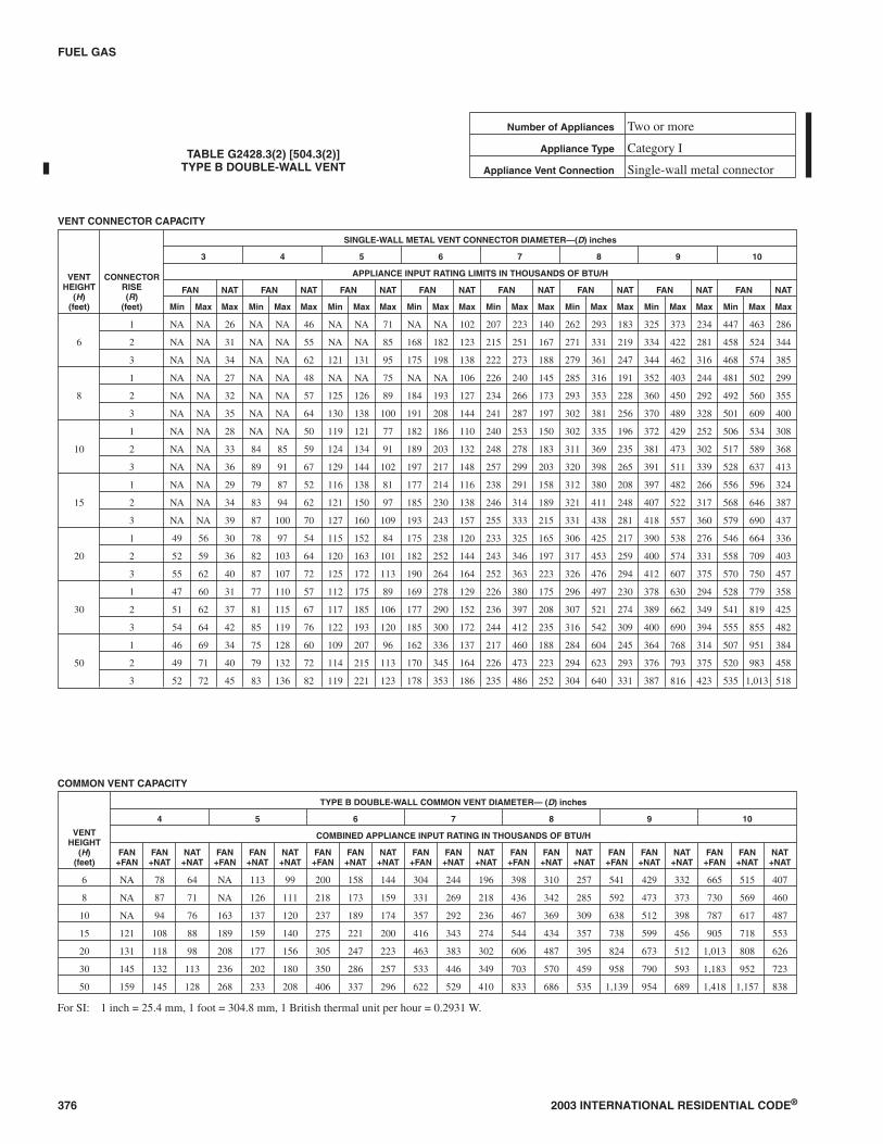
376 2003 INTERNATIONAL RESIDENTIAL CODE®
FUEL GAS
TABLE G2428.3(2) [504.3(2)]TYPE B DOUBLE-WALL VENT
Number of Appliances Two or more
Appliance Type Category I
Appliance Vent Connection Single-wall metal connector
VENT CONNECTOR CAPACITY
VENTHEIGHT
(H)(feet)
CONNECTORRISE(R)
(feet)
SINGLE-WALL METAL VENT CONNECTOR DIAMETER—(D) inches
3 4 5 6 7 8 9 10
APPLIANCE INPUT RATING LIMITS IN THOUSANDS OF BTU/H
FAN NAT FAN NAT FAN NAT FAN NAT FAN NAT FAN NAT FAN NAT FAN NAT
Min Max Max Min Max Max Min Max Max Min Max Max Min Max Max Min Max Max Min Max Max Min Max Max
6
1 NA NA 26 NA NA 46 NA NA 71 NA NA 102 207 223 140 262 293 183 325 373 234 447 463 286
2 NA NA 31 NA NA 55 NA NA 85 168 182 123 215 251 167 271 331 219 334 422 281 458 524 344
3 NA NA 34 NA NA 62 121 131 95 175 198 138 222 273 188 279 361 247 344 462 316 468 574 385
8
1 NA NA 27 NA NA 48 NA NA 75 NA NA 106 226 240 145 285 316 191 352 403 244 481 502 299
2 NA NA 32 NA NA 57 125 126 89 184 193 127 234 266 173 293 353 228 360 450 292 492 560 355
3 NA NA 35 NA NA 64 130 138 100 191 208 144 241 287 197 302 381 256 370 489 328 501 609 400
10
1 NA NA 28 NA NA 50 119 121 77 182 186 110 240 253 150 302 335 196 372 429 252 506 534 308
2 NA NA 33 84 85 59 124 134 91 189 203 132 248 278 183 311 369 235 381 473 302 517 589 368
3 NA NA 36 89 91 67 129 144 102 197 217 148 257 299 203 320 398 265 391 511 339 528 637 413
15
1 NA NA 29 79 87 52 116 138 81 177 214 116 238 291 158 312 380 208 397 482 266 556 596 324
2 NA NA 34 83 94 62 121 150 97 185 230 138 246 314 189 321 411 248 407 522 317 568 646 387
3 NA NA 39 87 100 70 127 160 109 193 243 157 255 333 215 331 438 281 418 557 360 579 690 437
20
1 49 56 30 78 97 54 115 152 84 175 238 120 233 325 165 306 425 217 390 538 276 546 664 336
2 52 59 36 82 103 64 120 163 101 182 252 144 243 346 197 317 453 259 400 574 331 558 709 403
3 55 62 40 87 107 72 125 172 113 190 264 164 252 363 223 326 476 294 412 607 375 570 750 457
30
1 47 60 31 77 110 57 112 175 89 169 278 129 226 380 175 296 497 230 378 630 294 528 779 358
2 51 62 37 81 115 67 117 185 106 177 290 152 236 397 208 307 521 274 389 662 349 541 819 425
3 54 64 42 85 119 76 122 193 120 185 300 172 244 412 235 316 542 309 400 690 394 555 855 482
50
1 46 69 34 75 128 60 109 207 96 162 336 137 217 460 188 284 604 245 364 768 314 507 951 384
2 49 71 40 79 132 72 114 215 113 170 345 164 226 473 223 294 623 293 376 793 375 520 983 458
3 52 72 45 83 136 82 119 221 123 178 353 186 235 486 252 304 640 331 387 816 423 535 1,013 518
COMMON VENT CAPACITY
VENTHEIGHT
(H)(feet)
TYPE B DOUBLE-WALL COMMON VENT DIAMETER— (D) inches
4 5 6 7 8 9 10
COMBINED APPLIANCE INPUT RATING IN THOUSANDS OF BTU/H
FAN+FAN
FAN+NAT
NAT+NAT
FAN+FAN
FAN+NAT
NAT+NAT
FAN+FAN
FAN+NAT
NAT+NAT
FAN+FAN
FAN+NAT
NAT+NAT
FAN+FAN
FAN+NAT
NAT+NAT
FAN+FAN
FAN+NAT
NAT+NAT
FAN+FAN
FAN+NAT
NAT+NAT
6 NA 78 64 NA 113 99 200 158 144 304 244 196 398 310 257 541 429 332 665 515 407
8 NA 87 71 NA 126 111 218 173 159 331 269 218 436 342 285 592 473 373 730 569 460
10 NA 94 76 163 137 120 237 189 174 357 292 236 467 369 309 638 512 398 787 617 487
15 121 108 88 189 159 140 275 221 200 416 343 274 544 434 357 738 599 456 905 718 553
20 131 118 98 208 177 156 305 247 223 463 383 302 606 487 395 824 673 512 1,013 808 626
30 145 132 113 236 202 180 350 286 257 533 446 349 703 570 459 958 790 593 1,183 952 723
50 159 145 128 268 233 208 406 337 296 622 529 410 833 686 535 1,139 954 689 1,418 1,157 838
For SI: 1 inch = 25.4 mm, 1 foot = 304.8 mm, 1 British thermal unit per hour = 0.2931 W.
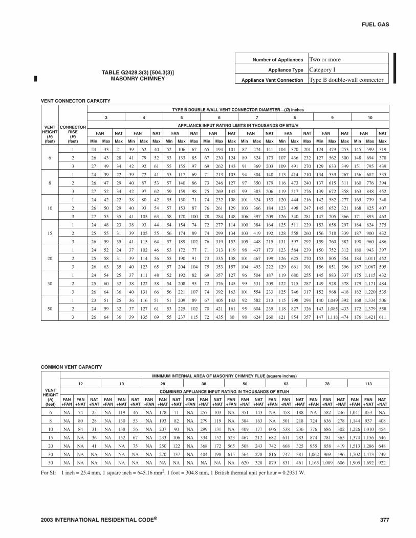
2003 INTERNATIONAL RESIDENTIAL CODE® 377
FUEL GAS
TABLE G2428.3(3) [504.3(3)]MASONRY CHIMNEY
Number of Appliances Two or more
Appliance Type Category I
Appliance Vent Connection Type B double-wall connector
VENT CONNECTOR CAPACITY
VENTHEIGHT
(H)(feet)
CONNECTORRISE(R)
(feet)
TYPE B DOUBLE-WALL VENT CONNECTOR DIAMETER—(D) inches
3 4 5 6 7 8 9 10
APPLIANCE INPUT RATING LIMITS IN THOUSANDS OF BTU/H
FAN NAT FAN NAT FAN NAT FAN NAT FAN NAT FAN NAT FAN NAT FAN NAT
Min Max Max Min Max Max Min Max Max Min Max Max Min Max Max Min Max Max Min Max Max Min Max Max
6
1 24 33 21 39 62 40 52 106 67 65 194 101 87 274 141 104 370 201 124 479 253 145 599 319
2 26 43 28 41 79 52 53 133 85 67 230 124 89 324 173 107 436 232 127 562 300 148 694 378
3 27 49 34 42 92 61 55 155 97 69 262 143 91 369 203 109 491 270 129 633 349 151 795 439
8
1 24 39 22 39 72 41 55 117 69 71 213 105 94 304 148 113 414 210 134 539 267 156 682 335
2 26 47 29 40 87 53 57 140 86 73 246 127 97 350 179 116 473 240 137 615 311 160 776 394
3 27 52 34 42 97 62 59 159 98 75 269 145 99 383 206 119 517 276 139 672 358 163 848 452
10
1 24 42 22 38 80 42 55 130 71 74 232 108 101 324 153 120 444 216 142 582 277 165 739 348
2 26 50 29 40 93 54 57 153 87 76 261 129 103 366 184 123 498 247 145 652 321 168 825 407
3 27 55 35 41 105 63 58 170 100 78 284 148 106 397 209 126 540 281 147 705 366 171 893 463
15
1 24 48 23 38 93 44 54 154 74 72 277 114 100 384 164 125 511 229 153 658 297 184 824 375
2 25 55 31 39 105 55 56 174 89 74 299 134 103 419 192 128 558 260 156 718 339 187 900 432
3 26 59 35 41 115 64 57 189 102 76 319 153 105 448 215 131 597 292 159 760 382 190 960 486
20
1 24 52 24 37 102 46 53 172 77 71 313 119 98 437 173 123 584 239 150 752 312 180 943 397
2 25 58 31 39 114 56 55 190 91 73 335 138 101 467 199 126 625 270 153 805 354 184 1,011 452
3 26 63 35 40 123 65 57 204 104 75 353 157 104 493 222 129 661 301 156 851 396 187 1,067 505
30
1 24 54 25 37 111 48 52 192 82 69 357 127 96 504 187 119 680 255 145 883 337 175 1,115 432
2 25 60 32 38 122 58 54 208 95 72 376 145 99 531 209 122 715 287 149 928 378 179 1,171 484
3 26 64 36 40 131 66 56 221 107 74 392 163 101 554 233 125 746 317 152 968 418 182 1,220 535
50
1 23 51 25 36 116 51 51 209 89 67 405 143 92 582 213 115 798 294 140 1,049 392 168 1,334 506
2 24 59 32 37 127 61 53 225 102 70 421 161 95 604 235 118 827 326 143 1,085 433 172 1,379 558
3 26 64 36 39 135 69 55 237 115 72 435 80 98 624 260 121 854 357 147 1,118 474 176 1,421 611
COMMON VENT CAPACITY
VENTHEIGHT
(H)(feet)
MINIMUM INTERNAL AREA OF MASONRY CHIMNEY FLUE (square inches)
12 19 28 38 50 63 78 113
COMBINED APPLIANCE INPUT RATING IN THOUSANDS OF BTU/H
FAN+FAN
FAN+NAT
NAT+NAT
FAN+FAN
FAN+NAT
NAT+NAT
FAN+FAN
FAN+NAT
NAT+NAT
FAN+FAN
FAN+NAT
NAT+NAT
FAN+FAN
FAN+NAT
NAT+NAT
FAN+FAN
FAN+NAT
NAT+NAT
FAN+FAN
FAN+NAT
NAT+NAT
FAN+FAN
FAN+NAT
NAT+NAT
6 NA 74 25 NA 119 46 NA 178 71 NA 257 103 NA 351 143 NA 458 188 NA 582 246 1,041 853 NA
8 NA 80 28 NA 130 53 NA 193 82 NA 279 119 NA 384 163 NA 501 218 724 636 278 1,144 937 408
10 NA 84 31 NA 138 56 NA 207 90 NA 299 131 NA 409 177 606 538 236 776 686 302 1,226 1,010 454
15 NA NA 36 NA 152 67 NA 233 106 NA 334 152 523 467 212 682 611 283 874 781 365 1,374 1,156 546
20 NA NA 41 NA NA 75 NA 250 122 NA 368 172 565 508 243 742 668 325 955 858 419 1,513 1,286 648
30 NA NA NA NA NA NA NA 270 137 NA 404 198 615 564 278 816 747 381 1,062 969 496 1,702 1,473 749
50 NA NA NA NA NA NA NA NA NA NA NA NA NA 620 328 879 831 461 1,165 1,089 606 1,905 1,692 922
For SI: 1 inch = 25.4 mm, 1 square inch = 645.16 mm2, 1 foot = 304.8 mm, 1 British thermal unit per hour = 0.2931 W.

378 2003 INTERNATIONAL RESIDENTIAL CODE®
FUEL GAS
TABLE G2428.3(4) [504.3(4)]MASONRY CHIMNEY
Number of Appliances Two or more
Appliance Type Category I
Appliance Vent Connection Single-wall metal connector
VENT CONNECTOR CAPACITY
VENTHEIGHT
(H)(feet)
CONNECTORRISE(R)
(feet)
SINGLE-WALL METAL VENT CONNECTOR DIAMETER (D)—inches
3 4 5 6 7 8 9 10
APPLIANCE INPUT RATING LIMITS IN THOUSANDS OF BTU/H
FAN NAT FAN NAT FAN NAT FAN NAT FAN NAT FAN NAT FAN NAT FAN NAT
Min Max Max Min Max Max Min Max Max Min Max Max Min Max Max Min Max Max Min Max Max Min Max Max
6
1 NA NA 21 NA NA 39 NA NA 66 179 191 100 231 271 140 292 366 200 362 474 252 499 594 316
2 NA NA 28 NA NA 52 NA NA 84 186 227 123 239 321 172 301 432 231 373 557 299 509 696 376
3 NA NA 34 NA NA 61 134 153 97 193 258 142 247 365 202 309 491 269 381 634 348 519 793 437
8
1 NA NA 21 NA NA 40 NA NA 68 195 208 103 250 298 146 313 407 207 387 530 263 529 672 331
2 NA NA 28 NA NA 52 137 139 85 202 240 125 258 343 177 323 465 238 397 607 309 540 766 391
3 NA NA 34 NA NA 62 143 156 98 210 264 145 266 376 205 332 509 274 407 663 356 551 838 450
10
1 NA NA 22 NA NA 41 130 151 70 202 225 106 267 316 151 333 434 213 410 571 273 558 727 343
2 NA NA 29 NA NA 53 136 150 86 210 255 128 276 358 181 343 489 244 420 640 317 569 813 403
3 NA NA 34 97 102 62 143 166 99 217 277 147 284 389 207 352 530 279 430 694 363 580 880 459
15
1 NA NA 23 NA NA 43 129 151 73 199 271 112 268 376 161 349 502 225 445 646 291 623 808 366
2 NA NA 30 92 103 54 135 170 88 207 295 132 277 411 189 359 548 256 456 706 334 634 884 424
3 NA NA 34 96 112 63 141 185 101 215 315 151 286 439 213 368 586 289 466 755 378 646 945 479
20
1 NA NA 23 87 99 45 128 167 76 197 303 117 265 425 169 345 569 235 439 734 306 614 921 347
2 NA NA 30 91 111 55 134 185 90 205 325 136 274 455 195 355 610 266 450 787 348 627 986 443
3 NA NA 35 96 119 64 140 199 103 213 343 154 282 481 219 365 644 298 461 831 391 639 1,042 496
30
1 NA NA 24 86 108 47 126 187 80 193 347 124 259 492 183 338 665 250 430 864 330 600 1,089 421
2 NA NA 31 91 119 57 132 203 93 201 366 142 269 518 205 348 699 282 442 908 372 613 1,145 473
3 NA NA 35 95 127 65 138 216 105 209 381 160 277 540 229 358 729 312 452 946 412 626 1,193 524
50
1 NA NA 24 85 113 50 124 204 87 188 392 139 252 567 208 328 778 287 417 1,022 383 582 1,302 492
2 NA NA 31 89 123 60 130 218 100 196 408 158 262 588 230 339 806 320 429 1,058 425 596 1,346 545
3 NA NA 35 94 131 68 136 231 112 205 422 176 271 607 255 349 831 351 440 1,090 466 610 1,386 597
COMMON VENT CAPACITY
VENTHEIGHT
(H)(feet)
MINIMUM INTERNAL AREA OF MASONRY CHIMNEY FLUE (square inches)
12 19 28 38 50 63 78 113
COMBINED APPLIANCE INPUT RATING IN THOUSANDS OF BTU/H
FAN+FAN
FAN+NAT
NAT+NAT
FAN+FAN
FAN+NAT
NAT+NAT
FAN+FAN
FAN+NAT
NAT+NAT
FAN+FAN
FAN+NAT
NAT+NAT
FAN+FAN
FAN+NAT
NAT+NAT
FAN+FAN
FAN+NAT
NAT+NAT
FAN+FAN
FAN+NAT
NAT+NAT
FAN+FAN
FAN+NAT
NAT+NAT
6 NA NA 25 NA 118 45 NA 176 71 NA 255 102 NA 348 142 NA 455 187 NA 579 245 NA 846 NA
8 NA NA 28 NA 128 52 NA 190 81 NA 276 118 NA 380 162 NA 497 217 NA 633 277 1,136 928 405
10 NA NA 31 NA 136 56 NA 205 89 NA 295 129 NA 405 175 NA 532 234 171 680 300 1,216 1,000 450
15 NA NA 36 NA NA 66 NA 230 105 NA 335 150 NA 400 210 677 602 280 866 772 360 1,359 1,139 540
20 NA NA NA NA NA 74 NA 247 120 NA 362 170 NA 503 240 765 661 321 947 849 415 1,495 1,264 640
30 NA NA NA NA NA NA NA NA 135 NA 398 195 NA 558 275 808 739 377 1,052 957 490 1,682 1,447 740
50 NA NA NA NA NA NA NA NA NA NA NA NA NA 612 325 NA 821 456 1,152 1,076 600 1,879 1,672 910
For SI: 1 inch = 25.4 mm, 1 square inch = 645.16 mm2, 1 foot = 304.8 mm, 1 British thermal unit per hour = 0.2931 W.

G2428.3.1 (504.3.1) Vent obstructions. These venting tablesshall not be used where obstructions, as described in SectionG2427.15, are installed in the venting system. The installationof vents serving listed appliances with vent dampers shall be inaccordance with the appliance manufacturer’s instructions orin accordance with the following:
1. The maximum capacity of the vent connector shall bedetermined using the NAT Max column.
2. The maximum capacity of the vertical vent or chim-ney shall be determined using the FAN+NAT columnwhen the second appliance is a fan-assisted appliance,or the NAT+NAT column when the second applianceis equipped with a draft hood.
3. The minimum capacity shall be determined as if theappliance were a fan-assisted appliance.
3.1. The minimum capacity of the vent connectorshall be determined using the FAN Min column.
3.2. The FAN+FAN column shall be used when thesecond appliance is a fan-assisted appliance, andthe FAN+NAT column shall be used when thesecond appliance is equipped with a draft hood,to determine whether the vertical vent or chim-ney configuration is not permitted (NA). Wherethe vent configuration is NA, the vent configura-tion shall not be permitted and an alternativeventing configuration shall be utilized.
G2428.3.2 (504.3.2) Connector length limit. The ventconnector shall be routed to the vent utilizing the shortestpossible route. Except as provided in Section G2428.3.3, themaximum vent connector horizontal length shall be 1.5 feet(457 mm) for each inch (18 mm per mm) of connector diam-eter as shown in Table G2428.3.2.
TABLE G2428.3.2 (504.3.2)MAXIMUM VENT CONNECTOR LENGTH
CONNECTOR DIAMETER CONNECTOR HORIZONTAL
Maximum(inches)
Length(feet)
3 4.5
4 6
5 7.5
6 9
7 10.5
8 12
9 13.5
For SI: 1 inch = 25.4 mm, 1 foot = 304.8 mm.
G2428.3.3 (504.3.3) Connectors with longer lengths.Connectors with longer horizontal lengths than those listedin Section G2428.3.2 are permitted under the following con-ditions:
1. The maximum capacity (FAN Max or NAT Max) ofthe vent connector shall be reduced 10 percent foreach additional multiple of the length listed above.For example, the maximum length listed above for a4-inch (102 mm) connector is 6 feet (1829 mm). Witha connector length greater than 6 feet (1829 mm), butnot exceeding 12 feet (3658 mm), the maximum ca-
pacity must be reduced by 10 percent (0.90 × maxi-mum vent connector capacity). With a connectorlength greater than 12 feet (3658 mm), but not exceed-ing 18 feet (5486 mm), the maximum capacity mustbe reduced by 20 percent (0.80 × maximum vent ca-pacity).
2. For a connector serving a fan-assisted appliance, theminimum capacity (FAN Min) of the connector shallbe determined by referring to the corresponding singleappliance table. For Type B double-wall connectors,Table G2428.2(1) shall be used. For single-wall con-nectors, Table G2428.2(2) shall be used. The height(H) and lateral (L) shall be measured according to theprocedures for a single appliance vent, as if the otherappliances were not present.
G2428.3.4 (504.3.4) Vent connector manifold. Where thevent connectors are combined prior to entering the verticalportion of the common vent to form a common vent mani-fold, the size of the common vent manifold and the commonvent shall be determined by applying a 10-percent reduction(0.90 × maximum common vent capacity) to the commonvent capacity part of the common vent tables. The length ofthe common vent connector manifold (LM) shall not exceed11/2 feet for each inch (457 mm per mm) of common ventconnector manifold diameter (D) (see Appendix B FigureB-11).
G2428.3.5 (504.3.5) Common vertical vent offset. Wherethe common vertical vent is offset, the maximum capacity ofthe common vent shall be reduced in accordance with Sec-tion G2428.3.6. The horizontal length of the common ventoffset (Lo) shall not exceed 11/2 feet for each inch (457 mmper mm) of common vent diameter.
G2428.3.6 (504.3.6) Elbows in vents. For each elbow up toand including 45 degrees (0.79 rad) in the common vent, themaximum common vent capacity listed in the venting tablesshall be reduced by 5 percent. For each elbow greater than45 degrees (0.79 rad) up to and including 90 degrees (1.57rad), the maximum common vent capacity listed in the vent-ing tables shall be reduced by 10 percent.
G2428.3.7 (504.3.7) Elbows in connectors. The vent con-nector capacities listed in the common vent sizing tables in-clude allowance for two 90-degree (1.57 rad) elbows. Foreach additional elbow up to and including 45 degrees (0.79rad), the maximum vent connector capacity listed in theventing tables shall be reduced by 5 percent. For each elbowgreater than 45 degrees (0.79 rad) up to and including 90 de-grees (1.57 rad), the maximum vent connector capacitylisted in the venting tables shall be reduced by 10 percent.
G2428.3.8 (504.3.8) Common vent minimum size. Thecross-sectional area of the common vent shall be equal to orgreater than the cross-sectional area of the largest connector.
G2428.3.9 (504.3.9) Common vent fittings. At the pointwhere tee or wye fittings connect to a common vent, theopening size of the fitting shall be equal to the size of thecommon vent. Such fittings shall not be prohibited fromhaving reduced-size openings at the point of connection ofappliance vent connectors.
2003 INTERNATIONAL RESIDENTIAL CODE® 379
FUEL GAS

G2428.3.10 (504.3.10) High altitude installations. Sea-level input ratings shall be used when determining maxi-mum capacity for high altitude installation. Actual input,derated for altitude, shall be used for determining minimumcapacity for high altitude installation.
G2428.3.11 (504.3.11) Connector rise measurement. Con-nector rise (R) for each appliance connector shall be mea-sured from the draft hood outlet or flue collar to thecenterline where the vent gas streams come together.
G2428.3.12 (504.3.12) Vent height measurement. Formultiple units of equipment all located on one floor, avail-able total height (H) shall be measured from the highestdraft hood outlet or flue collar up to the level of the outlet ofthe common vent.
G2428.3.13 (504.3.17) Vertical vent maximum size.Where two or more appliances are connected to a verticalvent or chimney, the flow area of the largest section of verti-cal vent or chimney shall not exceed seven times the small-est listed appliance categorized vent areas, flue collar area,or draft hood outlet area unless designed in accordance withapproved engineering methods.
G2428.3.14 (504.3.18) Multiple input rate appliances.For appliances with more than one input rate, the minimumvent connector capacity (FAN Min) determined from the ta-bles shall be less than the lowest appliance input rating, andthe maximum vent connector capacity (FAN Max or NATMax) determined from the tables shall be greater than thehighest appliance input rating.
G2428.3.15 (504.3.19) Liner system sizing. Listed, corru-gated metallic chimney liner systems in masonry chimneysshall be sized by using Table G2428.3(1) or G2428.3(2) forType B vents, with the maximum capacity reduced by 20percent (0.80 × maximum capacity) and the minimum ca-pacity as shown in Table G2428.3(1) or G2428.3(2). Corru-gated metallic liner systems installed with bends or offsetsshall have their maximum capacity further reduced in accor-dance with Sections G2428.3.5 and G2428.3.6. The 20-per-cent reduction for corrugated metallic chimney linersystems includes an allowance for one long-radius 90-de-gree (1.57 rad) turn at the bottom of the liner.
G2428.3.16 (504.3.20) Chimney and vent location. Ta-bles G2428.3(1), G2428.3(2), G2428.3(3) and G2428.3(4)shall be used for chimneys and vents not exposed to theoutdoors below the roof line. A Type B vent or listed chim-ney lining system passing through an unused masonrychimney flue shall not be considered to be exposed to theoutdoors.
Exception: Vents serving listed appliances installed inaccordance with the appliance manufacturer’s instruc-tions and the terms of the listing.
G2428.3.17 (504.3.21) Connector maximum and mini-mum size. Vent connectors shall not be increased in sizemore than two sizes greater than the listed appliance catego-rized vent diameter, flue collar diameter, or draft hood outletdiameter. Vent connectors for draft-hood-equipped appli-ances shall not be smaller than the draft hood outlet diame-ter. Where a vent connector size(s) determined from the
tables for a fan-assisted appliance(s) is smaller than the fluecollar diameter, the use of the smaller size(s) shall be per-mitted provided that the installation complies with all of thefollowing conditions:
1. Vent connectors for fan-assisted appliance flue collars12 inches (305 mm) in diameter or smaller are not re-duced by more than one table size [e.g., 12 inches to10 inches (305 mm to 254 mm) is a one-size reduc-tion] and those larger than 12 inches (305 mm) in di-ameter are not reduced more than two table sizes [e.g.,24 inches to 20 inches (610 mm to 508 mm) is atwo-size reduction].
2. The fan-assisted appliance(s) is common vented witha draft-hood-equipped appliances(s).
3. The vent connector has a smooth interior wall.
G2428.3.18 (504.3.22) Component commingling. Allcombinations of pipe sizes, single-wall, and double-wallmetal pipe shall be allowed within any connector run(s) orwithin the common vent, provided all of the appropriate ta-bles permit all of the desired sizes and types of pipe, as ifthey were used for the entire length of the subject connectoror vent. Where single-wall and Type B double-wall metalpipes are used for vent connectors within the same ventingsystem, the common vent must be sized using TableG2428.3(2) or G2428.3(4), as appropriate.
G2428.3.19 (504.3.23) Multiple sizes permitted. Where atable permits more than one diameter of pipe to be used for aconnector or vent, all the permitted sizes shall be permittedto be used.
G2428.3.20 (504.3.24) Table interpolation. Interpolationshall be permitted in calculating capacities for vent dimen-sions that fall between table entries. (See Example 3, Ap-pendix B.)
G2428.3.21 (504.3.25) Extrapolation prohibited. Extrap-olation beyond the table entries shall not be permitted.
G2428.3.22 (504.3.26) Engineering calculations. For ventheights lower than 6 feet (1829 mm) and greater than shownin the tables, engineering methods shall be used to calculatevent capacities.
SECTION G2429 (505)DIRECT-VENT, INTEGRAL VENT, MECHANICAL
VENT AND VENTILATION/EXHAUSTHOOD VENTING
G2429.1 (505.1) General. The installation of direct-vent andintegral vent appliances shall be in accordance with SectionG2427. Mechanical venting systems shall be designed and in-stalled in accordance with Section G2427.
SECTION G2430 (506)FACTORY-BUILT CHIMNEYS
G2430.1 (506.1) Listing. Factory-built chimneys for buildingheating appliances producing flue gases having a temperaturenot greater than 1,000°F (538°C), measured at the entrance tothe chimney, shall be listed and labeled in accordance with UL
380 2003 INTERNATIONAL RESIDENTIAL CODE®
FUEL GAS
103 and shall be installed and terminated in accordance withthe manufacturer’s installation instructions.
G2430.2 (506.2) Support. Where factory-built chimneys aresupported by structural members, such as joists and rafters,such members shall be designed to support the additionalload.
SECTION G2431 (601)GENERAL
G2431.1 (601.1) Scope. Sections G2431 through G2452 shallgovern the approval, design, installation, construction, mainte-nance, alteration and repair of the appliances and equipmentspecifically identified herein.
SECTION G2432 (602)DECORATIVE APPLIANCES FOR INSTALLATION
IN FIREPLACESG2432.1 (602.1) General. Decorative appliances for installa-tion in approved solid fuel burning fireplaces shall be tested inaccordance with ANSI Z21.60 and shall be installed in accor-dance with the manufacturer’s installation instructions.Manually lighted natural gas decorative appliances shall betested in accordance with ANSI Z21.84.
G2432.2 (602.2) Flame safeguard device. Decorative appli-ances for installation in approved solid fuel-burning fireplaces,with the exception of those tested in accordance with ANSIZ21.84, shall utilize a direct ignition device, an ignitor or a pilotflame to ignite the fuel at the main burner, and shall be equippedwith a flame safeguard device. The flame safeguard deviceshall automatically shut off the fuel supply to a main burner orgroup of burners when the means of ignition of such burners be-comes inoperative.
G2432.3 (602.3) Prohibited installations. Decorative appli-ances for installation in fireplaces shall not be installed whereprohibited by Section G2406.2.
SECTION G2433 (603)LOG LIGHTERS
G2433.1 (603.1) General. Log lighters shall be tested in accor-dance with IAS 8 and shall be installed in accordance with themanufacturer’s installation instructions.
SECTION G2434 (604)VENTED GAS FIREPLACES
(DECORATIVE APPLIANCES)G2434.1 (604.1) General. Vented gas fireplaces shall be testedin accordance with ANSI Z21.50, shall be installed in accor-dance with the manufacturer’s installation instructions andshall be designed and equipped as specified in SectionG2432.2.
G2434.2 (604.2) Access. Panels, grilles, and access doors thatare required to be removed for normal servicing operationsshall not be attached to the building.
SECTION G2435 (605)VENTED GAS FIREPLACE HEATERS
G2435.1 (605.1) General. Vented gas fireplace heaters shallbe installed in accordance with the manufacturer’s installationinstructions, shall be tested in accordance with ANSI Z21.88and shall be designed and equipped as specified in SectionG2432.2.
SECTION G2436 (607)VENTED WALL FURNACES
G2436.1 (608.1) General. Vented wall furnaces shall be testedin accordance with ANSI Z21.49 or Z21.86/CSA 2.32 andshall be installed in accordance with the manufacturer’s instal-lation instructions.
G2436.2 (608.2) Venting. Vented wall furnaces shall be ventedin accordance with Section G2427.
G2436.3 (608.3) Location. Vented wall furnaces shall be lo-cated so as not to cause a fire hazard to walls, floors, combusti-ble furnishings or doors. Vented wall furnaces installedbetween bathrooms and adjoining rooms shall not circulate airfrom bathrooms to other parts of the building.
G2436.4 (608.4) Door swing. Vented wall furnaces shall be lo-cated so that a door cannot swing within 12 inches (305 mm) ofan air inlet or air outlet of such furnace measured at right anglesto the opening. Doorstops or door closers shall not be installedto obtain this clearance.
G2436.5 (608.5) Ducts prohibited. Ducts shall not be at-tached to wall furnaces. Casing extension boots shall not be in-stalled unless listed as part of the appliance.
G2436.6 (608.6) Access. Vented wall furnaces shall be pro-vided with access for cleaning of heating surfaces, removal ofburners, replacement of sections, motors, controls, filters andother working parts, and for adjustments and lubrication ofparts requiring such attention. Panels, grilles and access doorsthat are required to be removed for normal servicing operationsshall not be attached to the building construction.
SECTION G2437 (609)FLOOR FURNACES
G2437.1 (609.1) General. Floor furnaces shall be tested in ac-cordance with ANSI Z21.48 or Z21.86/CSA 2.32 and shall beinstalled in accordance with the manufacturer’s installation in-structions.
G2437.2 (609.2) Placement. The following provisions applyto floor furnaces:
1. Floors. Floor furnaces shall not be installed in the floor ofany doorway, stairway landing, aisle or passageway of anyenclosure, public or private, or in an exitway from anysuch room or space.
2. Walls and corners. The register of a floor furnace with ahorizontal warm air outlet shall not be placed closer than 6inches (152 mm) to the nearest wall. A distance of at least18 inches (457 mm) from two adjoining sides of the floorfurnace register to walls shall be provided to eliminate thenecessity of occupants walking over the warm air dis-
2003 INTERNATIONAL RESIDENTIAL CODE® 381
FUEL GAS

FUEL GAS
charge. The remaining sides shall be permitted to be placed not closer than 6 inches (152 mm) to a wall. Wall-register models shall not be placed closer than 6 inches (152 mm) to a corner.
3. Draperies. The furnace shall be placed so that a door, drapery, or similar object cannot be nearer than 12 inches (305 mm) to any portion of the register of the furnace.
4. Floor construction. Floor furnaces shall not be installed in concrete floor construction built on grade.
5. Thermostat. The controlling thermostat for a floor furnace shall be located within the same room or space as the floor furnace or shall be located in an adjacent room or space that is permanently open to the room or space containing the floor furnace.
G2437.3 (609.3) Bracing. The floor around the furnace shall be braced and headed with a support framework designed in accordance with Chapter 5.
G2437.4 (609.4) Clearance. The lowest portion of the floor furnace shall have not less than a 6-inch (152 mm) clearance from the grade level; except where the lower 6-inch (152 mm) portion of the floor furnace is sealed by the manufacturer to prevent entrance of water, the minimum clearance shall be reduced to not less than 2 inches (51 mm). Where these clearances cannot be provided, the ground below and to the sides shall be excavated to form a pit under the furnace so that the required clearance is provided beneath the lowest portion of the furnace. A 12-inch (305 mm) minimum clearance shall be provided on all sides except the control side, which shall have an 18-inch (457 mm) minimum clearance.
G2437.5 (609.5) First floor installation. Where the basement story level below the floor in which a floor furnace is installed is utilized as habitable space, such floor furnaces shall be enclosed as specified in Section G2437.6 and shall project into a nonhabitable space.
G2437.6 (609.6) Upper floor installations. Floor furnaces installed in upper stories of buildings shall project below into nonhabitable space and shall be separated from the nonhabitable space by an enclosure constructed of noncombustible materials. The floor furnace shall be provided with access, clearance to all sides and bottom of not less than 6 inches (152 mm) and combustion air in accordance with Section G2407.
SECTION G2438 (613) CLOTHES DRYERS
G2438.1 (613.1) General. Clothes dryers shall be tested in accordance with ANSI Z21.5.1 and shall be installed in accordance with the manufacturer’s installation instructions.
SECTION G2439 (614) CLOTHES DRYER EXHAUST
G2439.1 (614.1) Installation. Clothes dryers shall be exhausted in accordance with the manufacturer’s instructions. Dryer exhaust systems shall be independent of all other systems and shall convey the moisture and any products of combustion to the outside of the building.
G2439.2 (614.2) Duct penetrations. Ducts that exhaust clothes dryers shall not penetrate or be located within any fireblocking, draftstopping or any wall, floor/ceiling or other assembly required
by this code to be fire-resistance rated, unless such duct is constructed of galvanized steel or aluminum of the thickness specified in the mechanical provisions of this code and the fire-resistance rating is maintained in accordance with this code. Fire dampers shall not be installed in clothes dryer exhaust duct systems.
G2439.3 (614.4) Exhaust installation. Dryer exhaust ducts for clothes dryers shall terminate on the outside of the building and shall be equipped with a backdraft damper. Screens shall not be installed at the duct termination. Ducts shall not be connected or installed with sheet metal screws or other fasteners that will obstruct the flow. Clothes dryer exhaust ducts shall not be connected to a vent connector, vent or chimney. Clothes dryer exhaust ducts shall not extend into or through ducts or plenums.
G2439.4 (614.5) Makeup air. Installations exhausting more than 200 cfm (0.09 m3/s) shall be provided with makeup air. Where a closet is designed for the installation of a clothes dryer, an opening having an area of not less than 100 square inches (0.0645 m2) for makeup air shall be provided in the closet enclosure, or makeup air shall be provided by other approved means.
G2439.5 (614.6) Clothes dryer ducts. Exhaust ducts for domestic clothes dryers shall be constructed of metal and shall have a smooth interior finish. The exhaust duct shall be a minimum nominal size of 4 inches (102 mm) in diameter. The entire exhaust system shall be supported and secured in place. The male end of the duct at overlapped duct joints shall extend in the direction of airflow. Clothes dryer transition ducts used to connect the appliance to the exhaust duct system shall be metal and limited to a single length not to exceed 8 feet (2438 mm) in length and shall be listed and labeled for the application. Transition ducts shall not be concealed within construction.
G2439.5.1 (614.6.1) Maximum length. The maximum length of a clothes dryer exhaust duct shall not exceed 25 feet (7620 mm) from the dryer location to the outlet terminal. The maximum length of the duct shall be reduced 21/2 feet (762 mm) for each 45 degree (0.79 rad) bend and 5 feet (1524 mm) for each 90 degree (1.6 rad) bend.
Exception: Where the make and model of the clothes dryer to be installed is known and the manufacturer’s installation instructions for such dryer are provided to the code official, the maximum length of the exhaust duct, including any transition duct, shall be permitted to be in accordance with the dryer manufacturer’s installation instructions.
G2439.5.2 (614.6.2) Rough-in-required. Where a compartment or space for a clothes dryer is provided, an exhaust duct system shall be installed.
G2439.5.3 Protection required. Clothes dryer exhaust ducts shall be protected by a steel plate or clip not less than 1/16 inch (1.59 mm) in thickness and of sufficient width to fully protect the duct. Plates or clips shall be placed on the finish face of all framing members which the clothes dryer exhaust duct passes through when there is less than 1 1/4 inch (32 mm) of framing material between the duct and the finish face. Plates or clips shall also be placed where nails or screws from finish or other work are likely to penetrate the clothes dryer exhaust duct.
382 2003 SEATTLE RESIDENTIAL CODE

SECTION G2440 (615)SAUNA HEATERS
G2440.1 (615.1) General. Sauna heaters shall be installed inaccordance with the manufacturer’s installation instructions.
G2440.2 (615.2) Location and protection. Sauna heatersshall be located so as to minimize the possibility of accidentalcontact by a person in the room.
G2440.2.1 (615.2.1) Guards. Sauna heaters shall be pro-tected from accidental contact by an approved guard or bar-rier of material having a low coefficient of thermalconductivity. The guard shall not substantially affect thetransfer of heat from the heater to the room.
G2440.3 (615.3) Access. Panels, grilles and access doors thatare required to be removed for normal servicing operations,shall not be attached to the building.
G2440.4 (615.4) Combustion and dilution air intakes. Saunaheaters of other than the direct-vent type shall be installed withthe draft hood and combustion air intake located outside thesauna room. Where the combustion air inlet and the draft hoodare in a dressing room adjacent to the sauna room, there shall beprovisions to prevent physically blocking the combustion airinlet and the draft hood inlet, and to prevent physical contactwith the draft hood and vent assembly, or warning notices shallbe posted to avoid such contact. Any warning notice shall beeasily readable, shall contrast with its background, and thewording shall be in letters not less than 0.25 inch (6.4 mm)high.
G2440.5 (615.5) Combustion and ventilation air. Combus-tion air shall not be taken from inside the sauna room. Combus-tion and ventilation air for a sauna heater not of the direct-venttype shall be provided to the area in which the combustion airinlet and draft hood are located in accordance with SectionG2407.
G2440.6 (615.6) Heat and time controls. Sauna heaters shallbe equipped with a thermostat which will limit room tempera-ture to 194°F (90°C). If the thermostat is not an integral part ofthe sauna heater, the heat-sensing element shall be locatedwithin 6 inches (152 mm) of the ceiling. If the heat-sensing ele-ment is a capillary tube and bulb, the assembly shall be attachedto the wall or other support, and shall be protected against phys-ical damage.
G2440.6.1 (615.6.1) Timers. A timer, if provided to controlmain burner operation, shall have a maximum operatingtime of 1 hour. The control for the timer shall be located out-side the sauna room.
G2440.7 (615.7) Sauna room. A ventilation opening into thesauna room shall be provided. The opening shall be not lessthan 4 inches by 8 inches (102 mm by 203 mm) located near thetop of the door into the sauna room.
SECTION G2441 (617)POOL AND SPA HEATERS
G2441.1 (617.1) General. Pool and spa heaters shall be testedin accordance with ANSI Z21.56 and shall be installed in ac-cordance with the manufacturer’s installation instructions.
SECTION G2442 (618)FORCED-AIR WARM-AIR FURNACES
G2442.1 (618.1) General. Forced-air warm-air furnaces shallbe tested in accordance with ANSI Z21.47 or UL 795 and shallbe installed in accordance with the manufacturer’s installationinstructions.
G2442.2 (618.2) Forced-air furnaces. The minimum unob-structed total area of the outside and return air ducts or open-ings to a forced-air warm-air furnace shall be not less than 2square inches for each 1,000 Btu/h (4402 mm2/W) output rat-ing capacity of the furnace and not less than that specified in thefurnace manufacturer’s installation instructions. The minimumunobstructed total area of supply ducts from a forced-airwarm-air furnace shall be not less than 2 square inches for each1,000 Btu/h (4402 mm2/W) output rating capacity of the fur-nace and not less than that specified in the furnace manufac-turer’s installation instructions.
Exception: The total area of the supply air ducts and outsideand return air ducts shall not be required to be larger than theminimum size required by the furnace manufacturer’s in-stallation instructions.
G2442.3 (618.3) Dampers. Volume dampers shall not beplaced in the air inlet to a furnace in a manner that will reducethe required air to the furnace.
G2442.4 (618.4) Circulating air ducts for forced-airwarm-air furnaces. Circulating air for forced-air-type,warm-air furnaces shall be conducted into the blower housingfrom outside the furnace enclosure by continuous air-tightducts.
G2442.5 (618.5) Prohibited sources. Outside or return air fora forced-air heating system shall not be taken from the follow-ing locations:
1. Closer than 10 feet (3048 mm) from an appliance ventoutlet, a vent opening from a plumbing drainage systemor the discharge outlet of an exhaust fan, unless the outletis 3 feet (914 mm) above the outside air inlet.
2. Where there is the presence of objectionable odors,fumes or flammable vapors; or where located less than10 feet (3048 mm) above the surface of any abutting pub-lic way or driveway; or where located at grade level by asidewalk, street, alley or driveway.
3. A room or space, the volume of which is less than 25 per-cent of the entire volume served by such system. Whereconnected by a permanent opening having an area sizedin accordance with Section G2442.2, adjoining rooms orspaces shall be considered as a single room or space for
2003 INTERNATIONAL RESIDENTIAL CODE® 383
FUEL GAS

the purpose of determining the volume of such rooms orspaces.
Exception: The minimum volume requirement shallnot apply where the amount of return air taken from aroom or space is less than or equal to the amount ofsupply air delivered to such room or space.
4. A room or space containing an appliance where such aroom or space serves as the sole source of return air.
Exception: This shall not apply where:
1. The appliance is a direct-vent appliance or anappliance not requiring a vent in accordancewith Section G2425.8.
2. The room or space complies with the followingrequirements:
2.1. The return air shall be taken from aroom or space having a volume exceed-ing 1 cubic foot (28 316.85 mm3) foreach 10 Btu/h (9.6 L/W) of combinedinput rating of all fuel-burning appli-ances therein.
2.2. The volume of supply air dischargedback into the same space shall be ap-proximately equal to the volume of re-turn air taken from the space.
2.3. Return-air inlets shall not be locatedwithin 10 feet (3048 mm) of any appli-ance firebox or draft hood in the sameroom or space.
3. Rooms or spaces containing solid-fuel burningappliances, provided that return-air inlets arelocated not less than 10 feet (3048 mm) fromthe firebox of such appliances.
5. A closet, bathroom, toilet room, kitchen, garage, me-chanical room, boiler room or furnace room.
G2442.6 (618.6) Screen. Required outdoor air inlets shall becovered with a screen having 1/4-inch (6.4 mm) openings. Re-quired outdoor air inlets serving a nonresidential portion of abuilding shall be covered with screen having openings largerthan 1/4 inch (6.4 mm) and not larger than 1 inch (25 mm).
G2442.7 (618.7) Return-air limitation. Return air from onedwelling unit shall not be discharged into another dwelling unit.
SECTION G2443 (619)CONVERSION BURNERS
G2443.1 (619.1) Conversion burners. The installation of con-version burners shall conform to ANSI Z21.8.
SECTION G2444 (620)UNIT HEATERS
G2444.1 (620.1) General. Unit heaters shall be tested in accor-dance with ANSI Z83.8 and shall be installed in accordancewith the manufacturer’s installation instructions.
G2444.2 (620.2) Support. Suspended-type unit heaters shallbe supported by elements that are designed and constructed to
accommodate the weight and dynamic loads. Hangers andbrackets shall be of noncombustible material.
G2444.3 (620.3) Ductwork. Ducts shall not be connected to aunit heater unless the heater is listed for such installation.
G2444.4 (620.4) Clearance. Suspended-type unit heaters shallbe installed with clearances to combustible materials of not lessthan 18 inches (457 mm) at the sides, 12 inches (305 mm) at thebottom and 6 inches (152 mm) above the top where the unitheater has an internal draft hood or 1 inch (25 mm) above thetop of the sloping side of the vertical draft hood.
Floor-mounted-type unit heaters shall be installed withclearances to combustible materials at the back and one sideonly of not less than 6 inches (152 mm). Where the flue gasesare vented horizontally, the 6-inch (152 mm) clearance shall bemeasured from the draft hood or vent instead of the rear wall ofthe unit heater. Floor-mounted-type unit heaters shall not be in-stalled on combustible floors unless listed for such installation.
Clearance for servicing all unit heaters shall be in accor-dance with the manufacturer’s installation instructions.
Exception: Unit heaters listed for reduced clearance shallbe permitted to be installed with such clearances in accor-dance with their listing and the manufacturer’s instructions.
SECTION G2445 (621)UNVENTED ROOM HEATERS
G2445.1 (621.1) General. Unvented room heaters shall betested in accordance with ANSI Z 21.11.2 and shall be installedin accordance with the conditions of the listing and the manu-facturer’s installation instructions.
G2445.2 (621.2) Prohibited use. One or more unvented roomheaters shall not be used as the sole source of comfort heating ina dwelling unit.
G2445.3 (621.3) Input rating. Unvented room heaters shallnot have an input rating in excess of 40,000 Btu/h (11.7 kW).
G2445.4 (621.4) Prohibited locations. The location ofunvented room heaters shall comply with Section G2406.2.
G2445.5 (621.5) Room or space volume. The aggregate inputrating of all unvented appliances installed in a room or spaceshall not exceed 20 Btu/h per cubic foot (0.21 kW/m3) of vol-ume of such room or space. Where the room or space in whichthe equipment is installed is directly connected to another roomor space by a doorway, archway or other opening of compara-ble size that cannot be closed, the volume of such adjacentroom or space shall be permitted to be included in the calcula-tions.
G2445.6 (621.6) Oxygen-depletion safety system. Unventedroom heaters shall be equipped with an oxygen-depletion-sen-sitive safety shutoff system. The system shall shut off the gassupply to the main and pilot burners when the oxygen in the sur-rounding atmosphere is depleted to the percent concentrationspecified by the manufacturer, but not lower than 18 percent.The system shall not incorporate field adjustment means capa-ble of changing the set point at which the system acts to shut offthe gas supply to the room heater.
384 2003 INTERNATIONAL RESIDENTIAL CODE®
FUEL GAS

G2445.7 (621.7) Unvented log heaters. An unvented logheater shall not be installed in a factory-built fireplace unlessthe fireplace system has been specifically tested, listed and la-beled for such use in accordance with UL 127.
SECTION G2446 (622)VENTED ROOM HEATERS
G2446.1 (622.1) General. Vented room heaters shall be testedin accordance with ANSI Z21.11.1 or ANSI Z21.86/CSA 2.32,shall be designed and equipped as specified in Section G2432.2and shall be installed in accordance with the manufacturer’s in-stallation instructions.
SECTION G2447 (623)COOKING APPLIANCES
G2447.1 (623.1) Cooking appliances. Cooking appliancesthat are designed for permanent installation, including ranges,ovens, stoves, broilers, grills, fryers, griddles, hot plates andbarbecues, shall be tested in accordance with ANSI Z21.1 orANSI Z21.58 and shall be installed in accordance with themanufacturer’s installation instructions.
G2447.2 (623.2) Prohibited location. Cooking appliances de-signed, tested, listed and labeled for use in commercial occu-pancies shall not be installed within dwelling units or withinany area where domestic cooking operations occur.
G2447.3 (623.3) Domestic appliances. Cooking appliancesinstalled within dwelling units and within areas where domes-tic cooking operations occur shall be listed and labeled ashousehold-type appliances for domestic use.
G2447.4 (623.4) Range installation. Ranges installed oncombustible floors shall be set on their own bases or legs andshall be installed with clearances of not less than that shown onthe label.
SECTION G2448 (624)WATER HEATERS
G2448.1 (624.1) General. Water heaters shall be tested in ac-cordance with ANSI Z 21.10.1 and ANSI Z 21.10.3 and shallbe installed in accordance with the manufacturer’s installationinstructions.
G2448.1.1 (624.1.1) Installation requirements. The re-quirements for water heaters relative to sizing, relief valves,drain pans and scald protection shall be in accordance withthis code.
G2448.2 (624.2) Water heaters utilized for space heating.Water heaters utilized both to supply potable hot water and pro-vide hot water for space-heating applications shall be listed andlabeled for such applications by the manufacturer and shall beinstalled in accordance with the manufacturer’s installation in-structions and this code.
SECTION G2449 (627)AIR CONDITIONING EQUIPMENT
G2449.1 (627.1) General. Air conditioning equipment shallbe tested in accordance with ANSI Z21.40.1 or ANSI Z21.40.2and shall be installed in accordance with the manufacturer’s in-stallation instructions.
G2449.2 (627.2) Independent piping. Gas piping servingheating equipment shall be permitted to also serve coolingequipment where such heating and cooling equipment cannotbe operated simultaneously. (See Section G2413.)
G2449.3 (627.3) Connection of gas engine-powered air con-ditioners. To protect against the effects of normal vibration inservice, gas engines shall not be rigidly connected to the gassupply piping.
G2449.4 (627.6) Installation. Air conditioning equipmentshall be installed in accordance with the manufacturer’s in-structions. Unless the equipment is listed for installation on acombustible surface such as a floor or roof, or unless the sur-face is protected in an approved manner, equipment shall be in-stalled on a surface of noncombustible construction withnoncombustible material and surface finish and with no com-bustible material against the underside thereof.
SECTION G2450 (628)ILLUMINATING APPLIANCES
G2450.1 (628.1) General. Illuminating appliances shall betested in accordance with ANSI Z21.42 and shall be installedin accordance with the manufacturer’s installation instruc-tions.
G2450.2 (628.2) Mounting on buildings. Illuminating appli-ances designed for wall or ceiling mounting shall be securelyattached to substantial structures in such a manner that they arenot dependent on the gas piping for support.
G2450.3 (628.3) Mounting on posts. Illuminating appliancesdesigned for post mounting shall be securely and rigidly at-tached to a post. Posts shall be rigidly mounted. The strengthand rigidity of posts greater than 3 feet (914 mm) in height shallbe at least equivalent to that of a 2.5-inch-diameter (64 mm)post constructed of 0.064-inch-thick (1.6 mm) steel or a 1-inch(25 mm) Schedule 40 steel pipe. Posts 3 feet (914 mm) or lessin height shall not be smaller than 3/4-inch (19.1 mm) Schedule40 steel pipe. Drain openings shall be provided near the base ofposts where there is a possibility of water collecting insidethem.
G2450.4 (628.4) Appliance pressure regulators. Where anappliance pressure regulator is not supplied with an illuminat-ing appliance and the service line is not equipped with a ser-vice pressure regulator, an appliance pressure regulator shallbe installed in the line to the illuminating appliance. For mul-tiple installations, one regulator of adequate capacity shall bepermitted to serve more than one illuminating appliance.
2003 INTERNATIONAL RESIDENTIAL CODE® 385
FUEL GAS

SECTION G2451 (630)INFRARED RADIANT HEATERS
G2451.1 (630.1) General. Infrared radiant heaters shall betested in accordance with ANSI Z 83.6 and shall be installedin accordance with the manufacturer’s installation instruc-tions.
G2451.2 (630.2) Support. Infrared radiant heaters shall besafely and adequately fixed in an approved position independ-ent of gas and electric supply lines. Hanger and brackets shallbe of noncombustible material.
SECTION G2452 (631)BOILERS
G2452.1 (631.1) Standards. Boilers shall be listed in accor-dance with the requirements of ANSI Z21.13 or UL 795. If ap-plicable, the boiler shall be designed and constructed inaccordance with the requirements of ASME CSD-1 and as ap-plicable, the ASME Boiler and Pressure Vessel Code, SectionsI, II, IV, V and IX and NFPA 85.
G2452.2 (631.2) Installation. In addition to the requirementsof this code, the installation of boilers shall be in accordancewith the manufacturer’s instructions and this code. Operatinginstructions of a permanent type shall be attached to the boiler.Boilers shall have all controls set, adjusted and tested by the in-staller. A complete control diagram together with completeboiler operating instructions shall be furnished by the installer.The manufacturer’s rating data and the nameplate shall be at-tached to the boiler.
G2452.3 (631.3) Clearance to combustible material. Clear-ances to combustible materials shall be in accordance with Sec-tion G2409.4.
SECTION G2453 (634)CHIMNEY DAMPER OPENING AREA
G2453.1 (634.1) Free opening area of chimney dampers.Where an unlisted decorative appliance for installation in avented fireplace is installed, the fireplace damper shall have apermanent free opening equal to or greater than specified in Ta-ble G2453.1.
386 2003 INTERNATIONAL RESIDENTIAL CODE®
FUEL GAS
TABLE G2453.1 (634.1)FREE OPENING AREA OF CHIMNEY DAMPER FOR VENTING FLUE GASES
FROM UNLISTED DECORATIVE APPLIANCES FOR INSTALLATION IN VENTED FIREPLACES
CHIMNEY HEIGHT(feet)
MINIMUM PERMANENT FREE OPENING(square inches)a
8 13 20 29 39 51 64
Appliance input rating (Btu per hour)
6 7,800 14,000 23,200 34,000 46,400 62,400 80,000
8 8,400 15,200 25,200 37,000 50,400 68,000 86,000
10 9,000 16,800 27,600 40,400 55,800 74,400 96,400
15 9,800 18,200 30,200 44,600 62,400 84,000 108,800
20 10,600 20,200 32,600 50,400 68,400 94,000 122,200
30 11,200 21,600 36,600 55,200 76,800 105,800 138,600
For SI: 1 foot = 304.8 mm, 1 square inch = 645.16 mm2, 1,000 Btu per hour = 0.293 kW.a. The first six minimum permanent free openings (8 square inches to 51 square inches) correspond approximately to the cross-sectional areas of chimneys having
diameters of 3 inches through 8 inches, respectively. The 64-square inch opening corresponds to the cross-sectional area of standard 8-inch by 8-inch chimney tile.