Embed Size (px)
Citation preview
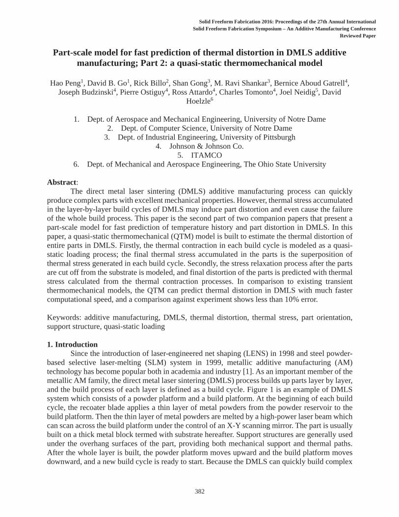
Part-scale model for fast prediction of thermal distortion in DMLS additive manufacturing; Part 2: a quasi-static thermomechanical model
Hao Peng1, David B. Go1, Rick Billo2, Shan Gong3, M. Ravi Shankar3, Bernice Aboud Gatrell4,Joseph Budzinski4, Pierre Ostiguy4, Ross Attardo4, Charles Tomonto4, Joel Neidig5, David
Hoelzle6
1. Dept. of Aerospace and Mechanical Engineering, University of Notre Dame2. Dept. of Computer Science, University of Notre Dame
3. Dept. of Industrial Engineering, University of Pittsburgh4. Johnson & Johnson Co.
5. ITAMCO6. Dept. of Mechanical and Aerospace Engineering, The Ohio State University
Abstract:The direct metal laser sintering (DMLS) additive manufacturing process can quickly
produce complex parts with excellent mechanical properties. However, thermal stress accumulated in the layer-by-layer build cycles of DMLS may induce part distortion and even cause the failure of the whole build process. This paper is the second part of two companion papers that present a part-scale model for fast prediction of temperature history and part distortion in DMLS. In this paper, a quasi-static thermomechanical (QTM) model is built to estimate the thermal distortion of entire parts in DMLS. Firstly, the thermal contraction in each build cycle is modeled as a quasi-static loading process; the final thermal stress accumulated in the parts is the superposition of thermal stress generated in each build cycle. Secondly, the stress relaxation process after the parts are cut off from the substrate is modeled, and final distortion of the parts is predicted with thermal stress calculated from the thermal contraction processes. In comparison to existing transient thermomechanical models, the QTM can predict thermal distortion in DMLS with much faster computational speed, and a comparison against experiment shows less than 10% error.
Keywords: additive manufacturing, DMLS, thermal distortion, thermal stress, part orientation, support structure, quasi-static loading
1. IntroductionSince the introduction of laser-engineered net shaping (LENS) in 1998 and steel powder-
based selective laser-melting (SLM) system in 1999, metallic additive manufacturing (AM) technology has become popular both in academia and industry [1]. As an important member of the metallic AM family, the direct metal laser sintering (DMLS) process builds up parts layer by layer, and the build process of each layer is defined as a build cycle. Figure 1 is an example of DMLS system which consists of a powder platform and a build platform. At the beginning of each build cycle, the recoater blade applies a thin layer of metal powders from the powder reservoir to the build platform. Then the thin layer of metal powders are melted by a high-power laser beam which can scan across the build platform under the control of an X-Y scanning mirror. The part is usually built on a thick metal block termed with substrate hereafter. Support structures are generally used under the overhang surfaces of the part, providing both mechanical support and thermal paths. After the whole layer is built, the powder platform moves upward and the build platform moves downward, and a new build cycle is ready to start. Because the DMLS can quickly build complex
382
Solid Freeform Fabrication 2016: Proceedings of the 2 th Annual InternationalSolid Freeform Fabrication Symposium – An Additive Manufacturing Conference
Reviewed Paper
Solid Freeform Fabrication 2016: Proceedings of the 27th Annual International
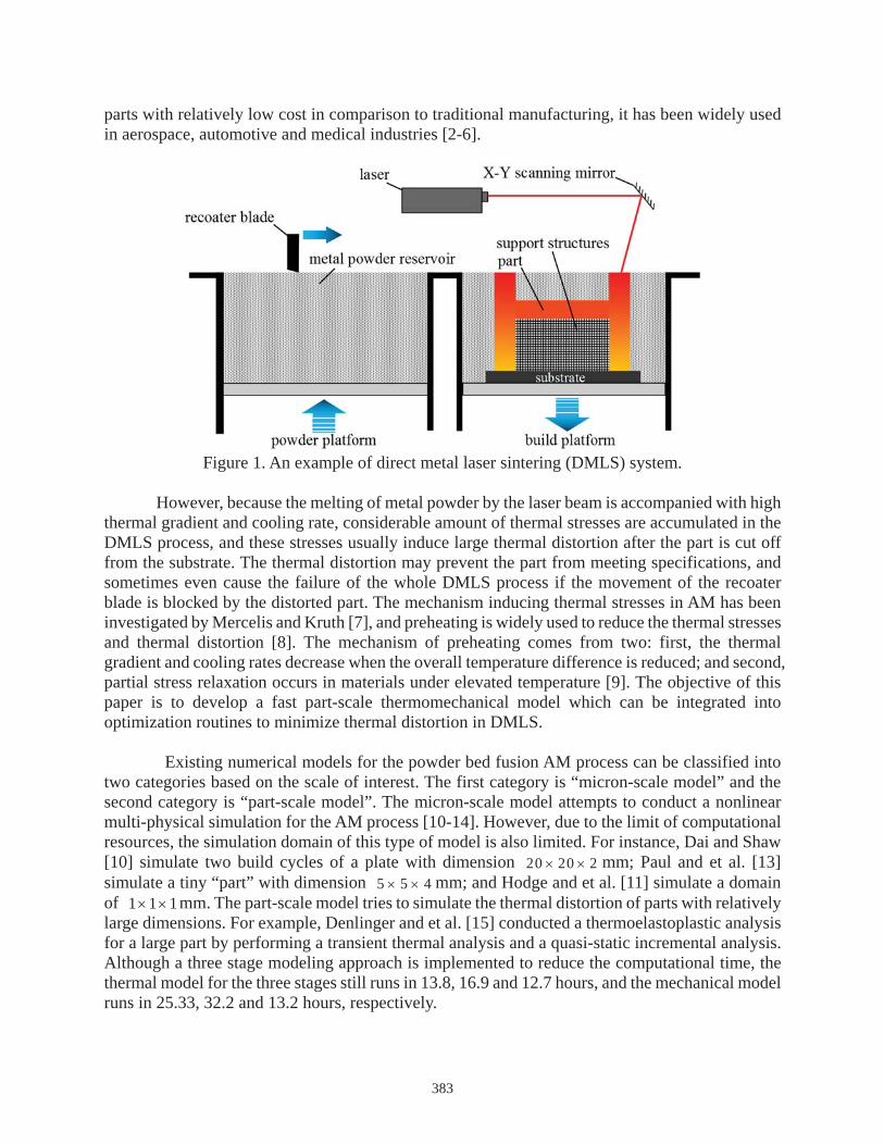
parts with relatively low cost in comparison to traditional manufacturing, it has been widely used in aerospace, automotive and medical industries [2-6].
Figure 1. An example of direct metal laser sintering (DMLS) system.
However, because the melting of metal powder by the laser beam is accompanied with high thermal gradient and cooling rate, considerable amount of thermal stresses are accumulated in the DMLS process, and these stresses usually induce large thermal distortion after the part is cut off from the substrate. The thermal distortion may prevent the part from meeting specifications, and sometimes even cause the failure of the whole DMLS process if the movement of the recoater blade is blocked by the distorted part. The mechanism inducing thermal stresses in AM has been investigated by Mercelis and Kruth [7], and preheating is widely used to reduce the thermal stresses and thermal distortion [8]. The mechanism of preheating comes from two: first, the thermal gradient and cooling rates decrease when the overall temperature difference is reduced; and second, partial stress relaxation occurs in materials under elevated temperature [9]. The objective of this paper is to develop a fast part-scale thermomechanical model which can be integrated into optimization routines to minimize thermal distortion in DMLS.
Existing numerical models for the powder bed fusion AM process can be classified into two categories based on the scale of interest. The first category is “micron-scale model” and the second category is “part-scale model”. The micron-scale model attempts to conduct a nonlinear multi-physical simulation for the AM process [10-14]. However, due to the limit of computational resources, the simulation domain of this type of model is also limited. For instance, Dai and Shaw [10] simulate two build cycles of a plate with dimension 20 20 2 mm; Paul and et al. [13] simulate a tiny “part” with dimension 5 5 4 mm; and Hodge and et al. [11] simulate a domain of 1 1 1mm. The part-scale model tries to simulate the thermal distortion of parts with relatively large dimensions. For example, Denlinger and et al. [15] conducted a thermoelastoplastic analysis for a large part by performing a transient thermal analysis and a quasi-static incremental analysis. Although a three stage modeling approach is implemented to reduce the computational time, the thermal model for the three stages still runs in 13.8, 16.9 and 12.7 hours, and the mechanical model runs in 25.33, 32.2 and 13.2 hours, respectively.
383

This paper presents a quasi-static thermomechanical model under the thermoelastic framework with thermal stress relaxation in melted layers [9, 16]. The model is generic to parts with arbitrary geometries by using STL files as model input. Part orientations and support structures are also included in the model. The structure of the paper is as follows: Section 1 introduces the DMLS process, and existing experimental and modeling work on DMLS process; Section 2 describes the quasi-static thermomechanical model in detail; Section 3 presents the experiment setup; Section 4 discuss the results from both the experiment and numerical model; and in Section 5, conclusions are given and future studies are discussed.
2. Model description 2.1. Model overview
Figure 2 shows an overview of the quasi-static thermomechanical model. The model can be generally divided into two steps. In the first step, the thermal stresses generated in each build cycle are predicted with the thermal contraction analysis. The temperature history obtained from the thermal circuit network (TCN) model in the first part of the two companion papers is used as input to predict thermal contraction in each build cycle. In the second step, the stresses accumulated in thermal contraction are used as initial stresses in the stress relaxation analysis. The final part distortion after the part is cut off from the substrate is predicted.
Figure 2. An overview of the quasi-static thermomechanical model.
2.2. Mechanism and assumptions The DMLS process can be divided into four stages as shown in Fig. 3(a).
Stage 1: Metal powders are melted by the laser beam and form a melt pool. Because porous metal powders are melted into full-density melt pool, shrinkage effect is significant in this stage [13]. Stage 2: The laser beam moves to other locations and the melt pool starts to cool down and solidify. During this stage, the melt pool is still in liquid phase, and thermal stresses in the melt pool is negligible.
384
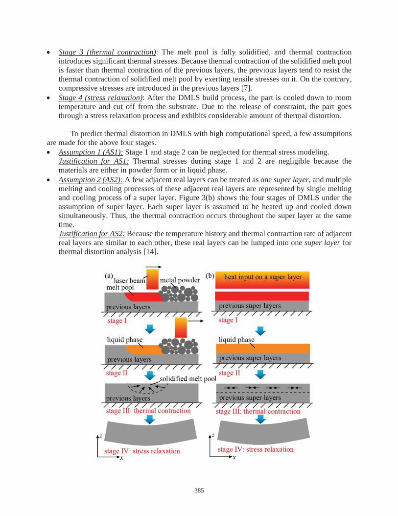
Stage 3 (thermal contraction): The melt pool is fully solidified, and thermal contraction introduces significant thermal stresses. Because thermal contraction of the solidified melt pool is faster than thermal contraction of the previous layers, the previous layers tend to resist the thermal contraction of solidified melt pool by exerting tensile stresses on it. On the contrary, compressive stresses are introduced in the previous layers [7]. Stage 4 (stress relaxation): After the DMLS build process, the part is cooled down to room temperature and cut off from the substrate. Due to the release of constraint, the part goes through a stress relaxation process and exhibits considerable amount of thermal distortion.
To predict thermal distortion in DMLS with high computational speed, a few assumptions are made for the above four stages.
Assumption 1 (AS1): Stage 1 and stage 2 can be neglected for thermal stress modeling. Justification for AS1: Thermal stresses during stage 1 and 2 are negligible because the materials are either in powder form or in liquid phase. Assumption 2 (AS2): A few adjacent real layers can be treated as one super layer, and multiple melting and cooling processes of these adjacent real layers are represented by single melting and cooling process of a super layer. Figure 3(b) shows the four stages of DMLS under the assumption of super layer. Each super layer is assumed to be heated up and cooled down simultaneously. Thus, the thermal contraction occurs throughout the super layer at the same time. Justification for AS2: Because the temperature history and thermal contraction rate of adjacent real layers are similar to each other, these real layers can be lumped into one super layer for thermal distortion analysis [14].
385
Figure 3. Four stages of DMLS process: (a) without super layer assumption and (b) with super layer assumptions (motivated by [7]).
Thermal contraction and quasi-static thermal loading In DMLS process, because the temperature decay in the newly deposited layer is always
faster than the previous layers, the thermal contraction in the newly deposited layer is also faster. Thus, each time when a new layer is built in a new build cycle, the new layer tends to apply a compressive loading on the previous layers. Since the build process of DMLS is long (ranging from a few hours to a few days), the thermal loading due to thermal contraction in each build cycle is assumed to be quasi-static.
Figure. 4 illustrates the quasi-static thermal loading in the DMLS process of three super layers. Figure 4(a) shows the temperature history of the three super layers. When the temperature drops below the solidus line, the super layer is fully solidified and further temperature drop induces thermal stresses in the super layers. If time instants when the thermal decay curves pass across the solidus line are denoted as 1t , 2t and 3t , the first quasi-static thermal loading process is from
1t to 2t , the second quasi-static loading process is from 2t to 3t , and the third quasi-static loading process is from 3t to the end, as shown in Fig. 4(a). Figure 4(b) shows the thermal loading process corresponding to the temperature history. The number of super layers in each thermal loading process increases from one to two to three. At each thermal loading process, thermal stresses are accumulated in the part. The thermal loading is compared to mechanical loading on a bar as shown in Fig. 4(c). Corresponding to each mechanical loading, there will be accumulated displacement and stresses in the bar. Here, an important assumption is made to estimate the final displacement and stresses of parts in the thermal contraction processes.
Assumption 3 (AS3): All thermal loading processes are independent, or in other words, deformation in the previous loading processes has little influence on the new thermal loading process. Thus, displacement and stresses in each thermal loading process can be obtained through parallel computation, and the final displacement and stresses are the superposition of displacement and stresses in each thermal loading processes. Justification for AS3: Before the part is cut off from the substrate, the deformation of the part is negligibly small (see section 4). Thus, the influence of deformation on the thermal loading process can be neglected.
386

Figure 4. Quasi-static thermal loading process: (a) temperature history in each super layer, (b) three quasi-static thermal loading processes, and (c) an analogy to quasi-static mechanical loading processes.
Stress relaxation and thermal distortion After the DMLS process, parts are usually cut off from the substrate with band saws. Due
to the release of constraint, the parts typically go through a stress relaxation process and significant distortion can be observed. The displacement of the parts in the stress relaxation process is generally much larger than the displacement during the thermal contraction process. Thus, the stress relaxation process of the parts can be modeled as a simple structural mechanics problem with zero initial displacement and pre-defined initial stresses. The pre-defined initial stresses are thermal stresses accumulated in the thermal contraction processes. In a common structural mechanics problem, displacement is specified as the initial condition and initial stresses are set to zero by default. Section 2.2 discussed how to simulate parts with initial stresses using the extended Hamilton’s principle [17].
2.2. Voxel-based finite element model Part and support structures in hexahedral voxels
After the model imports a part, the part is rotated to a user-specified orientation and support structures are generated under critical surfaces of the part. Critical surfaces are defined as overhanging surfaces with inclination angles less than 35 degrees to horizontal [18]. The detailed algorithm for support generation has been discussed in the first part of the two companion papers.
387
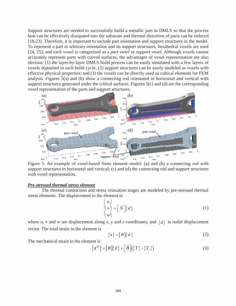
Support structures are needed to successfully build a metallic part in DMLS so that the process heat can be effectively dissipated into the substrate and thermal distortion of parts can be reduced [18-23]. Therefore, it is important to include part orientation and support structures in the model. To represent a part in arbitrary orientation and its support structures, hexahedral voxels are used [24, 25], and each voxel is categorized as a part voxel or support voxel. Although voxels cannot accurately represent parts with curved surfaces, the advantages of voxel representation are also obvious: (1) the layer-by-layer DMLS build process can be easily simulated with a few layers of voxels deposited in each build cycle; (2) support structures can be easily modeled as voxels with effective physical properties; and (3) the voxels can be directly used as cubical elements for FEM analysis. Figures 5(a) and (b) show a connecting rod orientated in horizontal and vertical with support structures generated under the critical surfaces. Figures 5(c) and (d) are the corresponding voxel representation of the parts and support structures.
Figure 5. An example of voxel-based finite element model: (a) and (b) a connecting rod with support structures in horizontal and vertical; (c) and (d) the connecting rod and support structures with voxel representation.
Pre-stressed thermal stress elementThe thermal contraction and stress relaxation stages are modeled by pre-stressed thermal
stress elements. The displacement in the element is
ˆuv N dw
(1)
where u, v and w are displacement along x, y and z coordinates, and d is nodal displacement vector. The total strain in the element is
B d (2) The mechanical strain in the element is
ˆMrB d B T T (3)
388
where T is temperature vector and rT is reference temperature vector. Matrices N̂ ,
B and B̂ are derived from the shape function. If the initial mechanical strain in the material
is 0M , the constitutive equation between stress and strain is denoted as
0= M MZ (4)
where Z is material property. To this point, the total strain, mechanical strain and stresses are denoted with nodal displacement and temperature.
Applying the extended Hamilton’s principle [17] gives 0ncW (5)
where , and ncW are variance of dynamic energy, elastic energy and external non-conservative work, which are defined as
, , , ,T
Vu v w u v w dV (6)
T
VdV (7)
, , boundary workTnc V
W u v w dVf (8)
where the superscript T represents transpose of a vector, is density, V is the volume of the element and f is gravity force in the element. The gravity force term can be omitted because gravity force is negligible compared to thermal stresses. Substituting Eq. (1) to Eq. (6) gives
ˆ ˆTT
Vd N dVN d (9)
Substituting Eqs. (2) and (4) to Eq. (7) gives
0ˆ ˆT T M
rVd B Z B d B T B T dV (10)
Substituting Eq. (1) to Eq. (8) gives ˆ boundary work
TTnc V
W dVd N f (11)
Substituting Eqs. (9-11) back to Eq. (5) gives the governing equation of the pre-stressed thermal stress element
e e eT e em d k d k T F Q (12) where T is the obtained from the thermal circuit network (TCN) model in the first part of the two companion paper, and the elemental matrices are
ˆ ˆT
e Vm N N dV (13)
Te V
k B Z B dV (14)
ˆTeT V
k B Z B dV (15)
0ˆ ˆT T T M
e rVF N B Z B T B Z dVf (16)
boundary workeQ (17)
389
where the initial mechanical strain 0M should be zero in the thermal contraction analysis, and
the initial mechanical strain in the stress relaxation stage is obtained from the thermal contraction analysis.
Modeling thermal contraction and stress relaxationThe thermal contraction in the layer-by-layer build process is modeled in a similar way to
the element birth and death method [13]. In each build cycle, a finite element model is built for all deposited super layers. The governing equation for all existing super layers can be written as
TK D K T F (18) where D is the nodal displacement of deposited elements, and K is the global stiffness matrix obtained by assembling elemental stiffness matrix ek of deposited elements. Similarly, global matrix TK and force vector F are obtained by assembling elemental matrix eTkand eF of deposited elements. Because gravity is negligible compared to thermal stresses and each thermal loading process is assumed to start without initial stresses, the elemental force vector can be simplified as
ˆTe rV
F B Z B T dV (19)
Because the thermal loading in each build cycle is quasi-static, the inertia term is not present Eq. (18). Besides, because no external forces are exerted on the part, the boundary work term is also gone. With more and more super layers deposited and more elements added to the system, the number of degree of freedom (DOF) associated with Eq. (18) keeps increasing until the last super layer is deposited.
The stress relaxation process is a special structural mechanics problem with non-zero initial stresses. The governing equation for the stress relaxation process is
K D F (20) where D is the nodal displacement of all elements, and K is the global stiffness matrix obtained by assembling elemental stiffness matrix ek of all elements. The force vector Fis obtained by assembling elemental force vector eF of all elements. Because no additional thermal stresses are introduced in the stress relaxation process, the elemental force vector can be simplified as
0T M
e VF B Z dV (21)
where 0M is the mechanical strain accumulated in thermal contraction processes.
3. Experiment description 3.1. Introduction of equipment
To validate the thermal distortion predicted by the model, various parts are built with one EOS M290 at University of Pittsburgh and another three EOS M290 at Johnson and Johnson. Three different kinds of metal powder feedstock are used including 316L stainless steel, AlSi10Mg and Ti6Al4V. Nitrogen is filled into the build chamber to protect the feedstock from oxidization. The EOS M290 comes with a building volume of 250 250 325 mm and a 400W Yb-fiber laser.
390

The scanning speed of the laser beam is up to 7.0m/s and the beam diameter is 100 microns. After the parts are manufactured, they are characterized by a high-precision Renishaw coordinate measuring machine (CMM) at University of Pittsburgh. The samples are firstly measured on the substrate and then measured again after being cut off from the substrate.
3.2. Experiment setup Considering the difficulties of quantifying thermal distortion of complex part, the
experiment begins with two simple geometries, a disk and rectangular bar. There are only two variables associated with the disk, diameter and thickness, and three variables associated with the bar, length, width and height. The thermal distortion of the disk and bar can be simply quantified by the radius of curvature of the top surfaces of the geometry.
Figure 6 shows the experiment setup for the disks. Figure 6(a) shows a failed DMLS process of a disk with diameter 75mm and thickness 5mm built from 316L stainless steel metal powder feedstock. As the disk was built up layer by layer, thermal stresses continued increasing between the substrate and the support structures, and the support structures finally peeled off from the substrate. Without the constraint of the substrate, significant distortion occurs at the top surface of the disk, which blocked the movement of the recoater blade and failed the DMLS process. Figure 6(b) shows 15 disks of diameter 45mm and thickness 5mm built at the center and four corners of the building volume from 316L stainless steel metal powder feedstock. The experiment is set up to test the influence of build location on the thermal distortion of disks. Figures 6(c) and (d) show disks with various diameter and thickness built from AlSi10Mg metal powder feedstock. Figure 6(c) shows disks with diameter of 45mm and thickness of 10mm, 15mm, 20mm and 30mm, and Fig. 6(d) shows disks with thickness of 5mm and diameter of 45mm, 55mm, 65mm, 70mm and 75mm. For disks specimens, only the top surfaces are measured by CMM and the data from measurement are fitted to a sphere.
391

Figure 6. Experiment setup for disks built horizontally: (a) a failed DMLS process due to peeling-off from the substrate, (b) coordinate measuring machine (CMM) working on 15 disks with 45mm diameter and 5mm thickness built at different locations of the build volume from 316L stainless steel powder feedstock, (c) disks with 45mm diameter and various thickness built from AlSi10Mg metal powder feedstock, and (d) disks with 5mm thickness and various diameters built from AlSi10Mg metal powder feedstock.
Figure 7(a) shows the experiment setup for bars built horizontally from 316L stainless steel metal powder feedstock. The cross-section of the bars are maintained to be a 10 10mm square, and the lengths of the bars are 25mm, 50mm, 75mm, 100mm, 125mm, 150mm and 175mm. For bar specimens, both the top and bottom surfaces are measured by CMM and the data are fitted to circle. Although the build processes of bars with various lengths are successful, the peeling-off of the bars from the substrate can be observed as shown in Fig. 7(b).
Figure 7. Experiment setup for bars built horizontally from 316L stainless steel metal powder feedstock: (a) bars with 10mm by 10mm cross-section and length of 25mm, 50mm, 75mm, 100mm, 125mm, 150mm and 175mm, (b) support structures peeling off from the substrate.
4. Results and validation A disk built horizontally
The thermal distortion of a disk built horizontally in DMLS is predicted with the quasi-static thermal stress model. The temperature history in the disk is predicted by a thermal circuit network (TCN) model proposed in the first part of the two companion paper. The geometry of the disk and parameters of the DMLS model is shown in table 1.
Parameters Value disk diameter 45mm disk thickness 5mm
number of super layers 10 thickness of a super layer 0.5 mm
Inter-layer dwell time 10secsubstrate temperature 100
room temperature 20material 316L Stainless Steel
Table 1. Geometry of the disk and parameters of the DMLS process
392
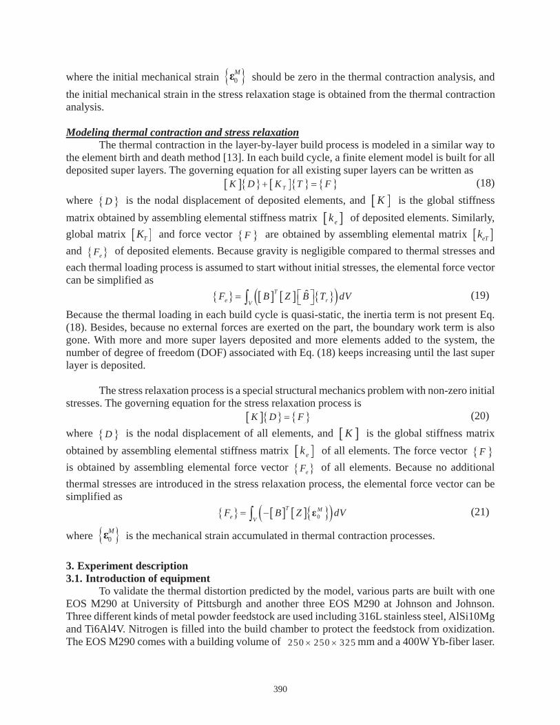
Figures 8(a) and (b) show the axial-direction displacement and von Mises stresses of the disk before being cut off from the substrate. The DMLS process of the disk is represented by ten build cycles of ten super layers. Each super layer is modeled with 3 voxels along z direction, and 15 by 15 voxels along x and y direction. No support structures are needed in the build process. Because the substrate is much larger and stiffer than the disk, the substrate is assumed to be maintained at 100 C during the build process and can be modeled as a rigid body. After the DMLS process, the disk is cooled down to room temperature 20 C . Figure 8(a) shows the displacement of the disk along axial direction. Because the bottom of the disk is fixed on the substrate, the displacement at the bottom of the disk is zero. The axial displacement is negative in most region of the disk because super layers tend to shrink under the thermal contraction. The only region showing positive axial displacement is located around the perimeter of the disk. This is because the perimeter of the disk is subject to pulling force from the center. No significant thermal distortion is observed before the disk is cut off from the substrate. The maximum axial displacement is about 60 microns, only 1.2% of the disk thickness. Figure 8(b) shows the corresponding von Mises stress in the disk. Because the bottom of the disk is fixed on the substrate, significant stress concentration can be found around the edge of the disk bottom. Because the model is based on elastic constitutive framework, the stresses are beyond the yield stress of 316L stainless steel. The stress concentration may induce the peeling-off of the disk from the substrate and cause the failure of the whole DMLS process as shown in Fig. 6(a).
Figure 8. A disk with diameter 45mm and thickness 5mm: (a) axial displacement of the disk on substrate, (b) von Mises stress of the disk on substrate, (c) axial displacement of the disk off substrate, and (d) von Mises stress of the disk off substrate.
393
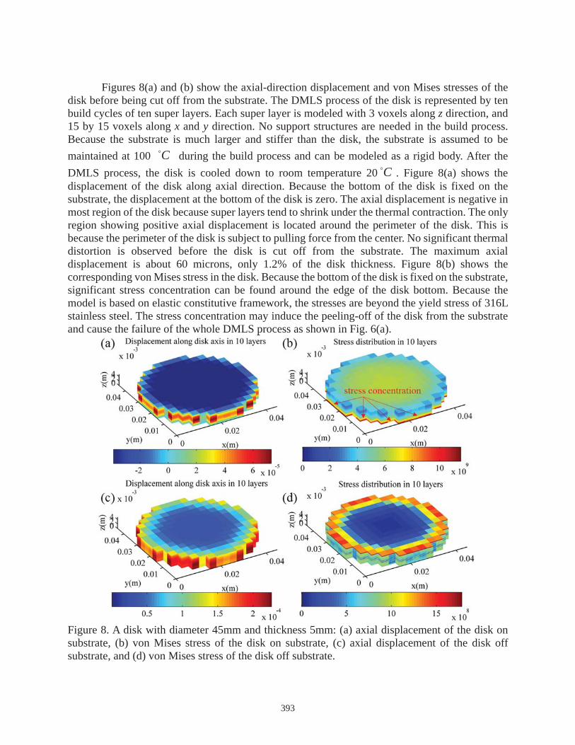
Figures 8(c) and (d) show the axial displacement and von Mises stress in the disk after the disk is cut off from the substrate. The edge of the disk bends upward and towards the center of the disk, and significant distortion of the disk can be observed. The maximum axial displacement is about 0.22mm, compared to 60 microns when the disk is on substrate. Both numerical and experimental results show that the disk bends into a “bowl” shape with large displacement along the edge and almost zero displacement at the center as shown in Fig. 9. The top surface of the disk can be well fitted to a sphere and the radius of curvature (ROC) is used to quantify the bending of the disk. The ROC from experiment is 1594mm and the ROC obtained from the model is 1721mm, 8% larger than the experimental result. The computational time of the thermal stress model is about 4 minutes, which is suitable for optimization analysis. Figure 8(d) shows that the maximum von Mises stress in the disk is reduced with more than one order of magnitude, while the inter-layer stress remains high and may induce the delamination.
Figure 9. The distorted shape of the disk after being cut off from the substrate: (a) experiment and (b) simulation.
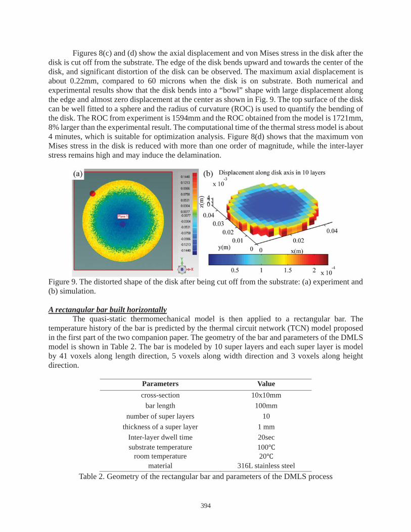
A rectangular bar built horizontallyThe quasi-static thermomechanical model is then applied to a rectangular bar. The
temperature history of the bar is predicted by the thermal circuit network (TCN) model proposed in the first part of the two companion paper. The geometry of the bar and parameters of the DMLS model is shown in Table 2. The bar is modeled by 10 super layers and each super layer is model by 41 voxels along length direction, 5 voxels along width direction and 3 voxels along height direction.
Parameters Value cross-section 10x10mm
bar length 100mmnumber of super layers 10
thickness of a super layer 1 mm Inter-layer dwell time 20secsubstrate temperature 100
room temperature 20material 316L stainless steel
Table 2. Geometry of the rectangular bar and parameters of the DMLS process
394

Figure 10(a) and (b) show the z-direction displacement and von Mises stresses in the rectangular bar. Due to thermal contraction, the bar tends to shrink and bend towards the center region. Thus, z-direction displacement at the center region of the bar is negative, while the surrounding materials are pulled upward and shows positive z-direction displacement. Because the primary thermal contraction is along the length direction, the largest z-direction displacement is at the two ends of the bar. The largest displacement is about 150 microns, 1.5% of the bar height. Figure 10(b) shows the von Mises stresses accumulated in the rectangular bar. Significant stress concentration can be observed at four bottom corners of the bar. The location of the stress concentration matches the experimental results shown in Fig. 7(b). Figure 10(c) shows the z-direction displacement of the bar off substrate. The largest displacement increases from 150 microns to about 0.45mm. The two ends of the bars bend towards the center region and the bending changes little along the y direction. The tops surface of the bar is fitted by a circle in xz plane and the radius of curvature (ROC) is 5588mm. The ROC obtained from the experiment is 2670mm. There are two possible explanation for the mismatch. First, the model does not account for the peeling-off from the substrate during the build process of the rectangular bars; second, plastic deformation is not included in the model. Although the accuracy of the model needs to be improved, the computational speed of the model is encouraging. It takes about 6 minutes to finish the simulation and future work will focus on improving the model accuracy while keeping the computational speed. Figure 10(d) shows the von Mises stress in the bar off substrate. Due to the release of the constraint at the bottom, the stresses decrease almost by one order of magnitude in comparison to stresses shown in Fig. 10(b). The inter-layer stresses are high and may induce delamination.
Figure 10. A rectangular bar with 10mm by 10mm cross-section and 100mm length: (a) z-direction displacement of the bar on substrate, (b) von Mises stress of the bar on substrate, (c) z-direction displacement of the bar off substrate, and (d) von Mises stress of the bar off substrate.
5. Conclusion and future studies In this paper, a quasi-static thermomechanical (QTM) model is built to estimate thermal
distortion of entire parts before and after the parts are cut off from the substrate. The QTM model simulates thermal contraction in each building cycle as a quasi-static loading process. The final thermal stress in the part is the superposition of thermal stresses in each build cycle. The model is
395

generic to parts with arbitrary geometries by using STL files as model input. Part orientation and support structures are also included in the model. The thermal distortion of a disk and a rectangular bar built in DMLS is simulated and the distortion is quantified by the radius of curvature (ROC) at the top surface of the disk and the bar. The simulation of the disk and bar takes about 4 minutes and 6 minutes, respectively. The ROC of the disk from simulation is only 8% larger than the experimental result and the ROC of the bar from simulation is about two times of the experimental results. Possible explanations for the mismatch in the bar are: (1) the model does not account for the peeling-off of the bar from the substrate; and (2) plastic deformation is not included in the model. Future studies will focus on (1) improving model accuracy while maintaining the computation speed; (2) analyzing part with different part orientation and support structures; and (3) integrating the model into an optimization routine to optimize part orientation and support structures for minimum thermal distortion.
Acknowledgements and Disclaimer This material is based on research sponsored by Air Force Research Laboratory under agreement number FA8650-12-2-7230. The U.S. Government is authorized to reproduce and distribute reprints for Governmental purposes notwithstanding any copyright notation thereon. The views and conclusions contained herein are those of the authors and should not be interpreted as necessarily representing the official policies or endorsements, either expressed or implied, of Air Force Research Laboratory or the U.S. Government. References [1] T. Wohlers, T. Gorne, History of Additive Manufacturing, in: Wohlers Report, 2014. [2] I. Gibson, D.W. Rosen, B. Stucker, Additive Manufacturing Technologies: Rapid Prototyping to Direct Digital Manufacturing, Springer US, 2009. [3] D.D. Gu, W. Meiners, K. Wissenbach, R. Poprawe, Laser additive manufacturing of metallic components: materials, processes and mechanisms, International Materials Reviews, 57 (2012) 133-164.[4] K.P. Karunakaran, A. Bernard, S. Suryakumar, L. Dembinski, G. Taillandier, Rapid manufacturing of metallic objects, Rapid Prototyping Journal, 18 (2012) 264-280. [5] L.E. Murr, S.M. Gaytan, D.A. Ramirez, E. Martinez, J. Hernandez, K.N. Amato, P.W. Shindo, F.R. Medina, R.B. Wicker, Metal Fabrication by Additive Manufacturing Using Laser and Electron Beam Melting Technologies, Journal of Materials Science & Technology, 28 (2012) 1-14. [6] B. Vayre, F. Vignat, F. Villeneuve, Metallic additive manufacturing: state-of-the-art review and prospects, Mechanics & Industry, 13 (2012) 89-96. [7] P. Mercelis, J.P. Kruth, Residual stresses in selective laser sintering and selective laser melting, Rapid Prototyping Journal, 12 (2006) 254 - 265. [8] P. Aggarangsi, J.L. Beuth, Localized Preheating Approaches for Reducing Residual Stress in Additive Manufacturing in: Solid Freeform Fabrication Proceedings, Austin, TX, 2006. [9] A.V. Gusarov, I.S. Malakhova-Ziablova, M.D. Pavlov, Thermoelastic Residual Stresses and Deformations at Laser Treatment, Physics Procedia, 41 (2013) 896-903. [10] K. Dai, L. Shaw, Thermal and mechanical finite element modeling of laser forming from metal and ceramic powders, Acta Materialia, 52 (2004) 69-80. [11] N.E. Hodge, R.M. Ferencz, J.M. Solberg, Implementation of a thermomechanical model for the simulation of selective laser melting, Computational Mechanics, 54 (2014) 33-51. [12] A. Hussein, L. Hao, C. Yan, R. Everson, Finite element simulation of the temperature and
396
stress fields in single layers built without-support in selective laser melting, Materials & Design, 52 (2013) 638-647. [13] R. Paul, S. Anand, F. Gerner, Effect of Thermal Deformation on Part Errors in Metal Powder Based Additive Manufacturing Processes, Journal of Manufacturing Science and Engineering, 136 (2014) 031009-031009. [14] M.F. Zaeh, G. Branner, Investigations on residual stresses and deformations in selective laser melting, Production Engineering, 4 (2010) 35-45. [15] E.R. Denlinger, J. Irwin, P. Michaleris, Thermomechanical Modeling of Additive Manufacturing Large Parts, Journal of Manufacturing Science and Engineering, 136 (2014) 061007-061007.[16] A.V. Gusarov, M. Pavlov, I. Smurov, Residual Stresses at Laser Surface Remelting and Additive Manufacturing, Physics Procedia, 12, Part A (2011) 248-254. [17] P.F. Pai, Highly Flexible Structures: Modeling, Computation, and Experimentation, American Institute of Aeronautics and Astronautics, 2007. [18] G. Strano, L. Hao, R.M. Everson, K.E. Evans, A new approach to the design and optimisation of support structures in additive manufacturing, The International Journal of Advanced Manufacturing Technology, 66 (2013) 1247-1254. [19] F. Calignano, Design optimization of supports for overhanging structures in aluminum and titanium alloys by selective laser melting, Materials & Design, 64 (2014) 203-213. [20] A. Hussein, L. Hao, C. Yan, R. Everson, P. Young, Advanced lattice support structures for metal additive manufacturing, Journal of Materials Processing Technology, 213 (2013) 1019-1026. [21] Y.-a. Jin, Y. He, J.-z. Fu, Support generation for additive manufacturing based on sliced data, The International Journal of Advanced Manufacturing Technology, (2015). [22] T.A. Krol, M.F. Zaeh, C. Seidel, Optimization of Supports in Metal-Based Additive Manufacturing by Means of Finite Element Models, (2012). [23] O. Poyraz, E. Yasa, G. Akbulut, A. Orhangul, S. Pilatin, Investigation of Support Structures for Direct Metal Laser Sintering (DMLS) Of In625 Parts, in: Annual International Solid Freeform Fabrication Symposium, 2015. [24] N. Keller, F. Neugebauer, H. Xu, V. Ploshikhin, Thermo-mechanical Simulation of ALM of Titanium Aerospace Structures, in: Proceedings DGM LightMAT, Deutsche Gesellschaft für Materialkunde e. V.,, 2013. [25] K. Subburaj, S. Patil, B. Ravi, Voxel-Based Thickness Analysis of Intricate Objects, International Journal of CAD CAM, 6 (2006) 105-115.
397