Embed Size (px)
Citation preview

TOYOTA RAV4 2016 - FOG LIGHT KIT Preparation
Page 1 of 18 pages Issue: C 11/17/2016
Part Number: PT413-42163
Kit Contents Item # Quantity Reqd. Description 1 7 7” Wire Tie 2 4 #10-16 Cross Pan-Washer Head
Screws 3 1 Switch 4 1 Relay 5 1 LH Fog Light Bezel 6 1 RH Fog Light Bezel 7 1 Switch Wire Harness 8 1 LH Fog Light 9 1 RH Fog Light 10 3 Scotchlok™ 11 3 Foam Pad
Hardware Bag Contents Item # Quantity Reqd. Description 1 2 3
Additional Items Required For Installation Item # Quantity Reqd. Description 1 2 3
Conflicts Factory fog lights (standard on XLE & Limited models)
General Applicability LE Grade RAV4
Recommended Sequence of Application Item # Accessory 1 2 3
*Mandatory
Recommended Tools Personal & Vehicle Protection
Notes
Blankets
Special Tools Notes Panel Removal Tool Hella Photometric Beam Setter (or equivalent)
DIO Only
Installation Tools Notes Ratchet Socket 10 mm, Deep Socket Extension 8” Diagonal Cutters Pliers Screwdriver #2 Phillips Screwdriver Small Flat-Blade Wrench 10mm
Special Chemicals Notes None
Vehicle Service Parts (may be required for reassembly) Item # Quantity Reqd. Description 1 2 3
Legend STOP: Damage to the vehicle may occur. Do not
proceed until process has been complied with.
OPERATOR SAFETY: Use caution to avoid risk of injury.
CAUTION: A process that must be carefully observed in order to reduce the risk of damage to the accessory/vehicle and to ensure a quality installation.
TOOLS & EQUIPMENT: Used in Figures calls out the specific tools and equipment recommended for this process.
REVISION MARK: This mark highlights a change in installation with respect to previous issue. SAFETY TORQUE: This mark indicates that torque is related to safety.

TOYOTA RAV4 2016 - FOG LIGHT KIT Procedure
Page 2 of 18 pages Issue: C 11/17/2016
Care must be taken when installing this accessory to ensure damage does not occur to the vehicle. The installation of this accessory should follow approved guidelines to ensure a quality installation. These guidelines can be found in the "Accessory Installation Practices" document. This document covers such items as:-
Vehicle Protection (use of covers and blankets, cleaning chemicals, etc.). Safety (eye protection, rechecking torque procedure, etc.). Vehicle Disassembly/Reassembly (panel removal, part storage, etc.). Electrical Component Disassembly/Reassembly (battery disconnection, connector removal, etc.).
Please see your Toyota dealer for a copy of this document.
1. Prepare for the Installation.
(a) The engine components and coolant may be
hot, use caution.
(b) Check the kit for contents and any damage.
(c) Protect the fender before starting.
(d) Remove the battery cable from the negative
terminal (Fig. 1-1).
CAUTION: Do not touch the positive terminal
with any tool.
2. Detach the Under Side Fender Liner.
(a) Raise the vehicle.
(b) Remove the three (3) fasteners indicated by
the circles (Fig. 2-1).
NOTE: Driver’s side shown.
Fig. 2-1
10 mm socket & ratchet
Fig. 1-1
10mm wrench or socket & ratchet
Negative lead

TOYOTA RAV4 2016 - FOG LIGHT KIT Procedure
Page 3 of 18 pages Issue: C 11/17/2016
(c) Remove the fastener indicated by the circle
(Fig. 2-2).
NOTE: Driver’s side shown.
(d) Repeat Steps 2(b) and 2(c) for the other side
of the vehicle.
(e) Save all eight (8) fasteners for reassembly.
3. Remove the Fill Panels.
(a) Locate the fog light connectors (both sides).
(b) Remove the tape to release the fog light
harness connectors (Fig. 3-1).
(c) Reach behind the underside/fender liner to
access the fill panels (Fig. 3-2).
(d) Remove the snap-fastener (Fig. 3-3).
(e) Press the insert inwards (Fig. 3-2).
(f) Use a panel removal tool to reach inside to
push open the tabs on the bumper as needed
(Fig. 3-2).
(g) Remove the connector (LH side only).
Fig. 2-2
Flat blade screwdriver
Fig. 3-1
Tape
Fog Light Connector
Fig. 3-3
Small flat blade screwdriver
Snap-fastener
Fig. 3-2
Panel removal tool

TOYOTA RAV4 2016 - FOG LIGHT KIT Procedure
Page 4 of 18 pages Issue: C 11/17/2016
(h) Remove the fastener indicated (Fig. 3-4, LH
side only).
4. Install the Fog Lights.
(a) Locate left and right fog light brackets.
(1) Verify the correct bracket for each side.
(2) Look for the “L” or “R” symbol indicated
by the circles (Fig. 4-1).
CAUTION: The brackets are marked RIGHT
and LEFT and will not fit if reversed.
(b) Install the fog lights into the respective (left
or right) brackets (Fig. 4-2).
(1) Insert the inboard tab into the bracket.
(2) Fasten the two other tabs with two (2)
supplied self-tapping screws.
(3) Install the assemblies to the vehicle.
CAUTION: The fog lights are marked
RIGHT and LEFT and will not fit if
reversed.
(4) Ensure all of the guides are fastened into
the bumper with an audible snap noise.
Fig. 4-1
“L” Left “R” Right
Fig. 4-2
#2 Phillips screwdriver
“L” Left “R” Right
Screws Screws
Fig. 3-4

TOYOTA RAV4 2016 - FOG LIGHT KIT Procedure
Page 5 of 18 pages Issue: C 11/17/2016
(c) Insert the snap-fastener removed in Step 3(d)
through the top hole in the cover. Install the
fog light & bracket assembly in the left side
and right side (Fig. 4-3).
NOTE: Passenger side shown.
(d) Plug the factory harness into the fog lights.
CAUTION: Make sure the connector snaps in
securely.
(e) Reassemble the underside/fender liner with
the four (4) fasteners removed in Step 2(b)
and 2(c) (Fig. 4-4 & Fig. 4-5).
(f) Lower the vehicle.
Fig. 4-3
Snap-fastener
Fig. 4-4
Flat blade screwdriver
Fig. 4-5
10 mm socket & ratchet

TOYOTA RAV4 2016 - FOG LIGHT KIT Procedure
Page 6 of 18 pages Issue: C 11/17/2016
5. Remove the Trim and Instrument Cluster.
The following steps are for FWD vehicles
only. Skip to Step 5(i) for AWD vehicles.
(a) Remove the upper trim panel (Fig. 5-1).
(1) Apply tape to the panel below the edge of
the upper trim panel (inset, Fig. 5-1).
(2) Use a nylon panel removal tool to
disengage the clip at the right end of the
upper trim (inset, Fig. 5-1).
(3) Carefully pull the trim away from the
instrument panel to disengage the
remainder of the clips.
(b) Remove the left air vent (Fig. 5-2).
(1) Place protective tape to the right side of
the dashboard by the air vent in the areas
indicated by arrows to protect the
surfaces.
(2) Use a nylon panel removal tool to loosen
the left air vent.
(3) Carefully pull the vent outward to
disengage the yellow clips (inset, Fig. 5-
2).
(c) Disengage the upper steering wheel cover
(Fig. 5-3).
(1) Adjust the steering wheel down and
rearward as far as possible.
(2) Disengage the steering wheel clips
indicated by circles.
Fig. 5-1
Panel removal tool
Fig. 5-2
Panel removal tool
Fig. 5-3
Panel removal tool

TOYOTA RAV4 2016 - FOG LIGHT KIT Procedure
Page 7 of 18 pages Issue: C 11/17/2016
(d) Lift the steering wheel cover (Fig. 5-4).
(e) Remove the instrument cluster bezel (Fig. 5-
5).
(1) Apply protective tape to the top portion
of the steering wheel cover.
(2) Disengage the bezel clips indicated by
circles and remove the bezel.
(f) Remove the instrument cluster (Fig. 5-6).
(1) Use a Phillip's screwdriver to remove the
two (2) screws indicated by arrows.
(2) Pull the instrument cluster partially
outward to disengage the two (2) clips
indicated by circles.
(3) Disconnect the connectors and remove
the instrument cluster (inset, Fig. 5-6).
(g) Locate the differential lock switch connector
indicated by the arrow. Un-tape the
connector from the harness behind the
instrument panel (Fig. 5-7).
Fig. 5-4
Fig. 5-5
Panel removal tool
Fig. 5-6
Phillips screwdriver
Fig. 5-7
TOYOTA RAV4 2016 - FOG LIGHT KIT Procedure
Page 8 of 18 pages Issue: C 11/17/2016
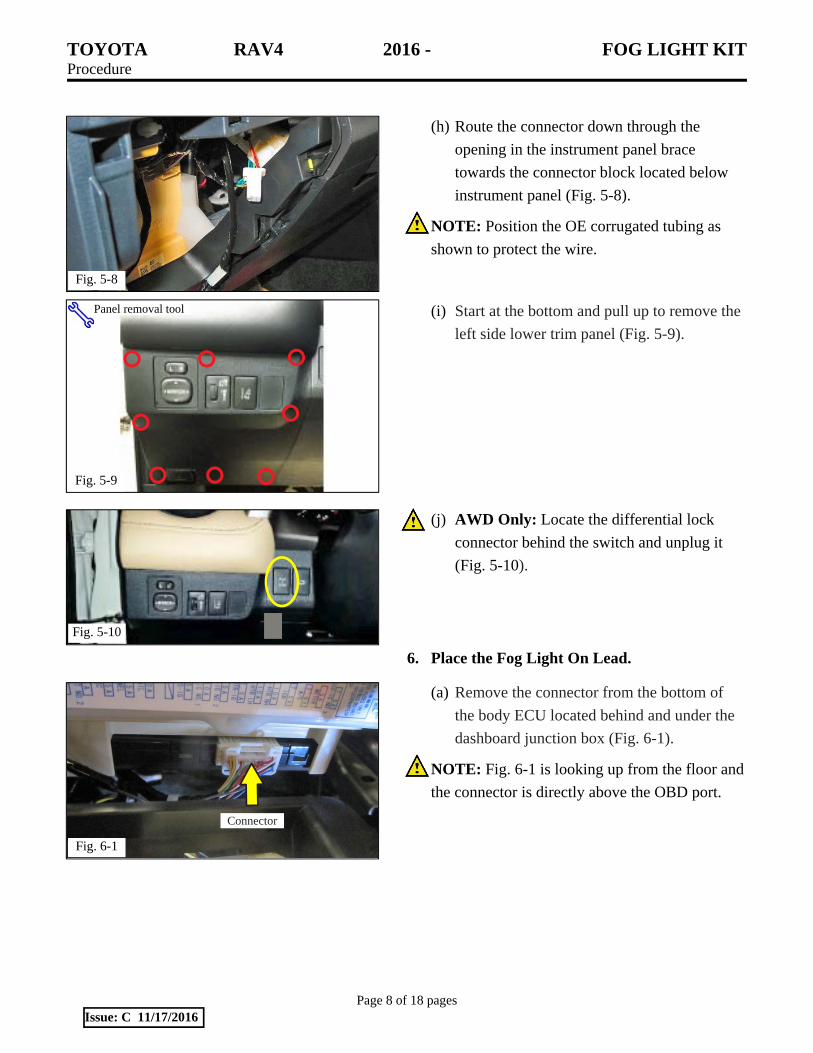
(h) Route the connector down through the
opening in the instrument panel brace
towards the connector block located below
instrument panel (Fig. 5-8).
NOTE: Position the OE corrugated tubing as
shown to protect the wire.
(i) Start at the bottom and pull up to remove the
left side lower trim panel (Fig. 5-9).
(j) AWD Only: Locate the differential lock
connector behind the switch and unplug it
(Fig. 5-10).
6. Place the Fog Light On Lead.
(a) Remove the connector from the bottom of
the body ECU located behind and under the
dashboard junction box (Fig. 6-1).
NOTE: Fig. 6-1 is looking up from the floor and
the connector is directly above the OBD port.
Fig. 6-1
Connector
Fig. 5-8
Fig. 5-9
Panel removal tool
Fig. 5-10

TOYOTA RAV4 2016 - FOG LIGHT KIT Procedure
Page 9 of 18 pages Issue: C 11/17/2016
(b) The grey lead on the switch harness (Fig. 6-
2) will be inserted into position 27 in the
vehicle BODY ECU harness (FOG LIGHT
ON) (Fig. 6-3).
(c) Use a small flat-blade screwdriver to gently
pry open the connector indicated by the
arrow (Fig. 6-4).
CAUTION: Take care to avoid damage to the
connector.
(d) Once the connector shell has been separated,
insert the terminal of the grey wire into
location 27 (Fig. 6-5).
(e) Verify the grey lead is correctly seated.
Fig. 6-4
Connection Side View
Insert screwdriver under tab to release
lower connector shell
Small flat-blade screwdriver
Fig. 6-5
Connection Side View
Location 27
Fig. 6-2
Beige leadWhite with black stripe
Terminal grey lead
Light blue lead
Fig. 6-3 Location 27
Wire Side View

TOYOTA RAV4 2016 - FOG LIGHT KIT Procedure
Page 10 of 18 pages Issue: C 11/17/2016
(f) Snap the lower connector shell onto the
connector (Fig. 6-6).
(g) Reconnect the connector (Fig. 6-7).
CAUTION: Be sure NOT to route the wire in
front of the fuse box cover.
(h) Secure the fog light harness with one (1) wire
tie (Fig. 6-8). Trim the excess wire tie.
Fig. 6-6
Connection Side View
Location 27
Fig. 6-7
Connector
Fig. 6-8
Wire tie #1

TOYOTA RAV4 2016 - FOG LIGHT KIT Procedure
Page 11 of 18 pages Issue: C 11/17/2016
(i) Route the harness up on the left side of the
junction block. Secure it with two (2) wire
ties (Fig. 6-9). Trim the excess wire tie.
CAUTION: Make sure to leave enough slack in
the wire so it does not rub up against the corner
of the junction box.
7. Connect the Ground Lead.
(a) Unlock the gray connector lock by pulling
outward (Fig. 7-1). Unplug the connector.
(b) Review the tutorial on the correct use of
Scotchlok™ connectors (Fig. 7-2).
Fig. 6-9
Wire tie #2
Wire tie #3
Fig. 7-2
Fig. 7-1

TOYOTA RAV4 2016 - FOG LIGHT KIT Procedure
Page 12 of 18 pages Issue: C 11/17/2016
(c) Locate the WHITE WITH BLACK STRIPE
wire on the fog light switch connector (Fig.
7-3).
(d) Locate the WHITE WITH BLACK STRIPE
wire in the vehicle connector (Fig. 7-4).
CAUTION: Verify the correct wire is used;
other white and black wires are for airbag
operation only.
(e) Remove/peel the black electrical tape as
necessary to allow room to apply the
Scotchlok™ in the following steps.
(f) Use a Scotchlok™ to connect the WHITE
WITH BLACK STRIPE lead of the fog light
switch connector to the WHITE WITH
BLACK STRIPE lead of the upper ECU
harness (Fig. 7-5).
CAUTION: Be sure to properly identify the
white with black stripe wires.
(g) Wrap the Scotchlok™ with one (1) foam
pad.
(h) Route the harness as shown (Fig. 7-6).
(1) Secure the harness with three (3) wire
ties.
(2) Trim the excess wire tie.
Fig. 7-3
White with black stripe
Fig. 7-4
Wire Side View
Fig. 7-5
Fig. 7-6

TOYOTA RAV4 2016 - FOG LIGHT KIT Procedure
Page 13 of 18 pages Issue: C 11/17/2016
(i) Add a foam pad (Fig. 7-7).
(j) Reconnect the connector and close the grey
lock (Fig. 7-7).
8. Connect the Illumination Lead.
(a) Locate the LIGHT BLUE lead in the fog
light switch harness (ILL -) (Fig. 8-1).
(b) Locate the BEIGE lead in the fog light
switch harness (ILL+) (Fig. 8-1).
(c) Remove/peel the black electrical tape on the
differential lock switch connector (Step 5(g)
or 5(j)) as necessary to allow room to apply
the Scotchloks™ in the following steps.
NOTE: Be sure to replace the tape after
installing the Scotchloks™.
(d) Use a Scotchlok™ to connect the LIGHT
BLUE lead of the fog light switch harness to
the LIGHT BLUE lead of the differential
lock harness (Fig. 8-2 & Fig. 8-3).
(e) Use a Scotchlok™ to connect the BEIGE
lead of the fog light switch connector to the
BEIGE lead of the differential lock harness
(Fig. 8-2 & Fig. 8-3).
Fig. 7-7 Foam pad
Fig. 8-1
Beige lead
Light blue lead
Fig. 8-2
Pin 7 (Light blue) ILL-Pin 8 (Beige) ILL+
Wire Side View
Fig. 8-3

TOYOTA RAV4 2016 - FOG LIGHT KIT Procedure
Page 14 of 18 pages Issue: C 11/17/2016
(f) Wrap the connection with one (1) foam pad
(Fig. 8-4).
(g) FWD Only: Use one (1) wire tie to secure
the differential lock switch connector to the
OE harness (Fig. 8-5). Trim the excess wire
tie.
(h) FWD Only: Wrap the unused differential
lock switch connector with one (1) foam pad
(Fig. 8-6).
(i) AWD Only: Reconnect the differential lock
switch disconnected in Step 5(j) (Fig. 8-7).
NOTE: The wire tie around the foam pads is not
used if the connector is plugged into the
differential lock switch. The wire tie is used on
FWD vehicles only.
Fig. 8-4
Fig. 8-5
Fig. 8-6
Fig. 8-7

TOYOTA RAV4 2016 - FOG LIGHT KIT Procedure
Page 15 of 18 pages Issue: C 11/17/2016
9. Install the Fog Light Switch.
(a) Remove the blank from the switch panel
(Fig. 9-1).
(b) Install the fog light switch in the inboard
knockout (Fig. 9-2).
NOTE: Make sure that the graphic is in the
indicated orientation.
(c) Connect the fog light switch connector to the
fog light switch (Fig. 9-3).
(d) Reconnect the rest of the connectors (Fig. 9-
3).
(e) Reattach the panel and all of the components.
Fig. 9-1
Fig. 9-2
Match orientation
Fig. 9-3
Fog light switch

TOYOTA RAV4 2016 - FOG LIGHT KIT Procedure
Page 16 of 18 pages Issue: C 11/17/2016
10. Install the Relay and Reconnect the Battery.
(a) Locate the relay housing on the passenger
side of the engine bay (Fig. 10-1).
(b) Remove the relay housing cover.
(c) Install the supplied relay in the location
indicated by the arrow (Fig. 10-2).
(d) Replace the relay housing cover.
(e) Reconnect the battery negative cable (Fig.
10-3).
Torque: 5.4 N·m (48 in·lbs)
CAUTION: Do not touch the positive terminal
with any tool.
Fig. 10-1
Relay Housing
Fig. 10-2
Install Relay Here
Fig. 10-3
10 mm socket & torque wrench
Negative lead
TOYOTA RAV4 2016 - FOG LIGHT KIT Procedure
Page 17 of 18 pages Issue: C 11/17/2016
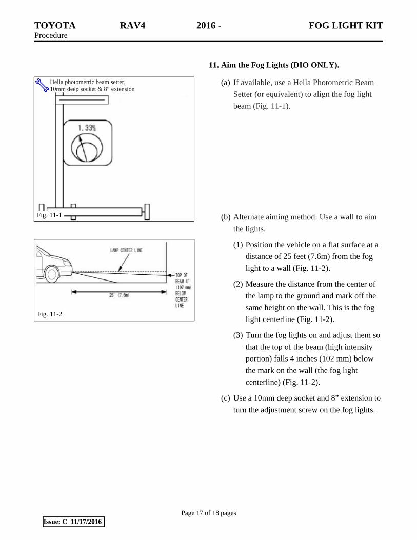
11. Aim the Fog Lights (DIO ONLY).
(a) If available, use a Hella Photometric Beam
Setter (or equivalent) to align the fog light
beam (Fig. 11-1).
(b) Alternate aiming method: Use a wall to aim
the lights.
(1) Position the vehicle on a flat surface at a
distance of 25 feet (7.6m) from the fog
light to a wall (Fig. 11-2).
(2) Measure the distance from the center of
the lamp to the ground and mark off the
same height on the wall. This is the fog
light centerline (Fig. 11-2).
(3) Turn the fog lights on and adjust them so
that the top of the beam (high intensity
portion) falls 4 inches (102 mm) below
the mark on the wall (the fog light
centerline) (Fig. 11-2).
(c) Use a 10mm deep socket and 8” extension to
turn the adjustment screw on the fog lights.
Fig. 11-1
Hella photometric beam setter, 10mm deep socket & 8” extension
Fig. 11-2

TOYOTA RAV4 2016 - FOG LIGHT KIT Checklist - these points MUST be checked to ensure a quality installation.
Check: Look For:
Page 18 of 18 pages Issue: C 11/17/2016
Accessory Function Checks
Install a short pin (if necessary)
Turn the headlights on
Check the fog light switch illumination
Turn the fog lights on
Switch the high beams on
Turn the headlights off
Check the fog light switch orientation
Vehicle Function Checks
Taillights/brake lights/turn signals
Reverse lights & emergency flashers
Mirror & dimmer controls
Traction control
Differential lock switch (if equipped)
Negative battery cable torque
Headlights function as normal
Switch lights up
Fog lights turn on
High beams on/Fog lights off
Headlights and fog lights turn off
The lamp symbol faces left
All function properly
Function properly
Function properly
Functions properly
Functions properly
5.4 N·m (48 in·lbs)
Vehicle Appearance Check
After accessory installation and removal of protective cover(s), perform a visual inspection.
Ensure no damage (including scuffs and scratches) was caused during the installation process. (For PPO installations, refer to TMS Accessory Quality Shipping Standard.)