Embed Size (px)
Citation preview
BUTTON SEWING AND NECK WRAPPING
MODEL CBS 13
This manual is valid from the machine Serial No.: T CBS0002
PART NUMBER 97.7300.0.000
MACHINE SERIAL No:
11 / 2015

BUTTON SEWING AND NECK WRAPPING
MACHINE SERIAL No:
MODEL MODEL CBS 13
PART NUMBER 97.7300.0.000This manual is valid from the machine Serial No.: T CBS0002
11 / 2015


97.
7300
.0.0
00 B
UTT
ON
SEW
ING
AN
D N
ECK
WR
APPI
NG
PAR
TS A
ND
SER
VIC
E M
ANU
AL
97.
7300
.0.0
00 B
UTT
ON
SEW
ING
AN
D N
ECK
WR
APPI
NG
PAR
TS A
ND
SER
VIC
E M
ANU
AL
97.
7300
.0.0
00 B
UTT
ON
SEW
ING
AN
D N
ECK
WR
APPI
NG
PAR
TS A
ND
SER
VIC
E M
ANU
AL
97.
7300
.0.0
00 B
UTT
ON
SEW
ING
AN
D N
ECK
WR
APPI
NG
PAR
TS A
ND
SER
VIC
E M
ANU
AL
97.
7300
.0.0
00 B
UTT
ON
SEW
ING
AN
D N
ECK
WR
APPI
NG
PAR
TS A
ND
SER
VIC
E M
ANU
AL
97.
7300
.0.0
00 B
UTT
ON
SEW
ING
AN
D N
ECK
WR
APPI
NG
PAR
TS A
ND
SER
VIC
E M
ANU
AL
CB
S 13
CB
S 13
CB
S 13
CB
S 13
CB
S 13
CB
S 13

LIMITED WARRANTY ON NEW AMF REECE EQUIPMENT
Warranty provisions:
A ninety (90) day limited service labor warranty to correct defects in installation, workmanship, or mate-rial without charge for labor. This portion of the warranty applies to machines sold as ”installed” only.
A one (1) year limited material warranty on major component parts to replace materials with defects. Any new part believed defective must be returned freight prepaid to AMF Reece, Inc. for inspection. If, upon inspection, the part or material is determined to be defective, AMF Reece, Inc. will replace it without charge to the customer for parts or material.
Service labor warranty period shall begin on the completed installation date. Material warranty shall be-gin on the date the equipment is shipped from AMF Reece, Inc.
Exclusions:
Excluded from both service labor warranty and material warranty are: (1) Consumable parts which would be normally considered replaceable in day-to-day operations. These include parts such as nee-dles, knives, loopers and spreaders. (2) Normal adjustment and routine maintenance. This is the sole responsibility of the customer. (3) Cleaning and lubrication of equipment. (4) Parts found to be altered, broken or damaged due to neglect or improper installation or application. (5) Damage caused by the use of non-Genuine AMF Reece parts. (6) Shipping or delivery charges.
There is no service labor warranty for machines sold as ”uninstalled”.
Equipment installed without the assistance of a certified technician (either an AMF Reece Employee, a Certified Contractor, or that of an Authorized Distributor) will have the limited material warranty only. Only the defective material will be covered. Any charges associated with the use of an AMF Reece Technician or that of a Distributor to replace the defective part will be the customer’s responsibility.
NO OTHER WARRANTY, EXPRESS OR IMPLIED, AS TO DESCRIPTION, QUALITY, MERCHANTABIL-ITY, and FITNESS FOR A PARTICULAR PURPOSE, OR ANY OTHER MATTER IS GIVEN BY SELLER OR SELLER’S AGENT IN CONNECTION HEREWITH. UNDER NO CIRCUMSTANCES SHALL SELL-ER OR SELLER’S AGENT BE LIABLE FOR LOSS OF PROFITS OR ANY OTHER DIRECT OR INDI-RECT COSTS, EXPENSES, LOSSES OR DAMAGES ARISING OUT OF DEFECTS IN OR FAILURE OF THE EQUIPMENT OR ANY PART THEREOF.
WHAT TO DO IF THERE IS A QUESTION REGARDING WARRANTY
If a machine is purchased through an authorized AMF Reece, Inc. distributor, warranty questions should be first directed to that distributor. However, the satisfaction and goodwill of our customers are of pri-mary concern to AMF Reece, Inc. In the event that a warranty matter is not handled to your satisfaction, please contact AMF Reece office:
Prostejov, Czech RepublicPhone: (+420) 582-309-275Fax: (+420) 582-360-608e-mail: [email protected]

Warranty Registration Card (Please Fax or Mail immediately after installation)
Note: All Warranty Claims Void, unless Registration Card on file at AMF Reece HQ
Machine model number:(S101, S100, S104, S105, S311, Decostitch, S4000, EBS Mark II, etc)
Manufacturer‘s serial or production number:
Installation Site Information:
Customer‘s Name:
Customer‘s Mailing Address:
Customer‘s Telephone Number:
Supervising Mechanic‘s or Technician‘s Name:
Signature of Supervising Technician:
AMF Reece Technician‘s Name:
AMF Reece Technician‘s Signature:
Type of garment produced at this location?
Average Daily Production Expected from this machine?(number of buttonholes, jackets sewn, pants produced, buttons sewn, etc)
Any special requirements required at this location?
What other AMF Reece Machines are at this location?
How can we serve you better?

Released: 11/2015E-mail: [email protected]; webside: amfreece.comPhone: +420 582 309 146; Fax: +420 582 360 606
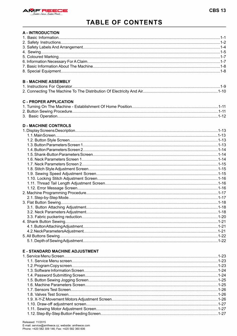
TABLE OF CONTENTSA - INTRODUCTION1. Basic Information..................................................................................................................................................1-1 2. Safety Instructions................................................................................................................................................1-23. Safety Labels And Arrangement............................................................................................................................1-44. Sewing..................................................................................................................................................................1-55. Coloured Marking..................................................................................................................................................1-76. Information Necessary For A Claim........................................................................................................................1-77. Basic Information About The Machine...................................................................................................................1-88. Special Equipment................................................................................................................................................1-8
B - MACHINE ASSEMBLY1. Instructions For Operator......................................................................................................................................1-92. Connecting The Machine To The Distribution Of Electricity And Air....................................................................1-10
C - PROPER APPLICATION1. Turning On The Machine - Establishment Of Home Position..............................................................................1-112. Button Sewing Procedure....................................................................................................................................1-113. Basic Operation.................................................................................................................................................1-12
D - MACHINE CONTROLS1. Display Screens Description.................................................................................................................................1-13
1.1. Main Screen...................................................................................................................................................1-131.2. Button Style Screen......................................................................................................................................1-131.3. Button Parameters Screen 1..........................................................................................................................1-131.4. Button Parameters Screen 2..........................................................................................................................1-141.5. Shank-Button Parameters Screen.................................................................................................................1-141.6. Neck Parameters Screen 1...........................................................................................................................1-141.7. Neck Parameters Screen 2...........................................................................................................................1-151.8. Stitch Style Adjustment Screen.....................................................................................................................1-151.9. Sewing Speed Adjustment Screen..............................................................................................................1-151.10. Locking Stitch Adjustment Screen.............................................................................................................1-161.11. Thread Tail Length Adjustment Screen......................................................................................................1-161.12. Error Message Screen...............................................................................................................................1-16
2. Machine Programming Procedure.......................................................................................................................1-172.1. Step-by-Step Mode.......................................................................................................................................1-17
3. Flat Button Sewing..............................................................................................................................................1-183.1. Button Attaching Adjustment.......................................................................................................................1-183.2. Neck Parameters Adjustment.......................................................................................................................1-183.3. Fabric puckering reduction...........................................................................................................................1-20
4. Shank Button Sewing..........................................................................................................................................1-214.1. Button Attaching Adjustment..........................................................................................................................1-214.2. Neck Parameters Adjustment..........................................................................................................................1-21
5. All Buttons Sewing...............................................................................................................................................1-225.1. Depth of Sewing Adjustment..........................................................................................................................1-22
E - STANDARD MACHINE ADJUSTMENT1. Service Menu Screen...........................................................................................................................................1-23
1.1. Service Menu screen....................................................................................................................................1-231.2. Program Copy screen....................................................................................................................................1-231.3. Software Information Screen.........................................................................................................................1-241.4. Password Submitting Screen........................................................................................................................1-241.5. Button Sewing Jogging Screen.....................................................................................................................1-251.6. Machine Parameters Screen........................................................................................................................1-251.7. Sensors Test Screen.....................................................................................................................................1-261.8. Valves Test Screen.......................................................................................................................................1-261.9. X-Y-Z Movement Motors Adjustment Screen................................................................................................1-261.10. Draw-off adjustment screen.......................................................................................................................1-271.11. Sewing Motor Adjustment Screen..............................................................................................................1-271.12. Step-By-Step Button Feeding Screen..........................................................................................................1-27
CBS 13
Released: 11/2015E-mail: [email protected]; webside: amfreece.com
Phone: +420 582 309 146; Fax: +420 582 360 606
TABLE OF CONTENTS
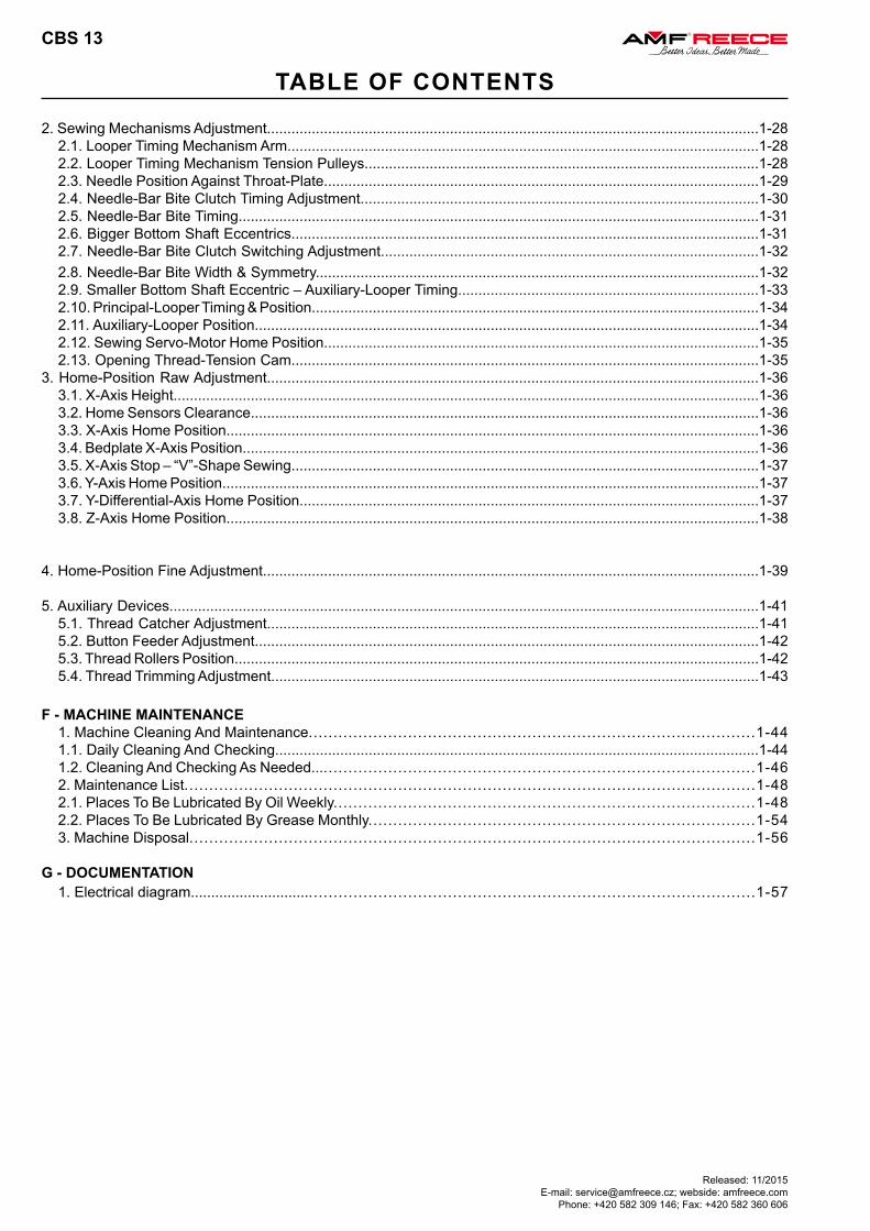
2. Sewing Mechanisms Adjustment.........................................................................................................................1-282.1. Looper Timing Mechanism Arm....................................................................................................................1-28 2.2. Looper Timing Mechanism Tension Pulleys.................................................................................................1-282.3. Needle Position Against Throat-Plate...........................................................................................................1-29 2.4. Needle-Bar Bite Clutch Timing Adjustment..................................................................................................1-302.5. Needle-Bar Bite Timing................................................................................................................................1-31 2.6. Bigger Bottom Shaft Eccentrics...................................................................................................................1-312.7. Needle-Bar Bite Clutch Switching Adjustment.............................................................................................1-322.8. Needle-Bar Bite Width & Symmetry.............................................................................................................1-322.9. Smaller Bottom Shaft Eccentric – Auxiliary-Looper Timing..........................................................................1-332.10. Principal-Looper Timing & Position..............................................................................................................1-342.11. Auxiliary-Looper Position............................................................................................................................1-342.12. Sewing Servo-Motor Home Position...........................................................................................................1-352.13. Opening Thread-Tension Cam...................................................................................................................1-35
3. Home-Position Raw Adjustment.........................................................................................................................1-363.1. X-Axis Height................................................................................................................................................1-363.2. Home Sensors Clearance.............................................................................................................................1-363.3. X-Axis Home Position...................................................................................................................................1-363.4. Bedplate X-Axis Position...............................................................................................................................1-363.5. X-Axis Stop – “V”-Shape Sewing...................................................................................................................1-373.6. Y-Axis Home Position....................................................................................................................................1-373.7. Y-Differential-Axis Home Position.................................................................................................................1-373.8. Z-Axis Home Position...................................................................................................................................1-38
4. Home-Position Fine Adjustment..........................................................................................................................1-39
5. Auxiliary Devices.................................................................................................................................................1-415.1. Thread Catcher Adjustment.........................................................................................................................1-415.2. Button Feeder Adjustment............................................................................................................................1-425.3. Thread Rollers Position.................................................................................................................................1-425.4. Thread Trimming Adjustment........................................................................................................................1-43
F - MACHINE MAINTENANCE 1. Machine Cleaning And Maintenance..........................................................................................1-44 1.1. Daily Cleaning And Checking.......................................................................................................................1-44 1.2. Cleaning And Checking As Needed..........................................................................................1-46 2. Maintenance List...................................................................................................................1-48 2.1. Places To Be Lubricated By Oil Weekly.....................................................................................1-48 2.2. Places To Be Lubricated By Grease Monthly..............................................................................1-54 3. Machine Disposal..................................................................................................................1-56
G - DOCUMENTATION 1. Electrical diagram.......................................................................................................................1-57
CBS 13
CBS 13
1-1
A - INTRODUCTION
Released: 11/2015E-mail: [email protected]; webside: amfreece.comPhone: +420 582 309 146; Fax: +420 582 360 606
1. BASIC INFORMATION
Thank you for buying our electronic button sewing machine CBS 13. This sewing machine is intended for sewing buttons on outwear and other button sewing applications. It has been designed and manufactured to be reliable and easy to operate. Special attention has been paid to ensure ease, effectiveness and safety for machine operators and servicemen.
Safety mechanisms protect both, operators and the machine, and respect valid safety and hygiene provisions for usual technological usage of the machine. Those safety mechanisms include electrical plug, operation switch (circuit breaker) and covers ensuring safety operation of the machine only if they are fitted onto the machine correctly.
There are information labels on the machine to point out additional danger. Do not remove or damage those labels. Mentioned warnings cannot cover all safety aspects and therefore it is very important for the operator to read this manual carefully and understand it well before he/she starts operating the machine. It will also eliminate errors during machine installation and its operation. Do not put the machine into operation unless you have read all the manuals supplied with the machine and have understood each function and procedure.
We recommend that servicemen from AMF Reece supervise the installation of the machine and initial training of your mechanics and operators. The most effective method ensuring safety of operators working on the machine is a strict safety program including instructions for safety operation. Operators and servicemen should wear safety glasses.
CBS 13
1-2 Released: 11/2015E-mail: [email protected]; webside: amfreece.com
Phone: +420 582 309 146; Fax: +420 582 360 606
A - INTRODUCTION
2. SAFETY INSTRUCTIONS
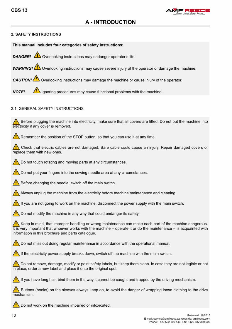
This manual includes four categories of safety instructions:
DANGER! Overlooking instructions may endanger operator’s life.
WARNING! Overlooking instructions may cause severe injury of the operator or damage the machine.
CAUTION! Overlooking instructions may damage the machine or cause injury of the operator.
NOTE! Ignoring procedures may cause functional problems with the machine.
2.1. GENERAL SAFETY INSTRUCTIONS
Before plugging the machine into electricity, make sure that all covers are fitted. Do not put the machine into electricity if any cover is removed.
Remember the position of the STOP button, so that you can use it at any time.
Check that electric cables are not damaged. Bare cable could cause an injury. Repair damaged covers or replace them with new ones.
Do not touch rotating and moving parts at any circumstances.
Do not put your fingers into the sewing needle area at any circumstances.
Before changing the needle, switch off the main switch.
Always unplug the machine from the electricity before machine maintenance and cleaning.
If you are not going to work on the machine, disconnect the power supply with the main switch.
Do not modify the machine in any way that could endanger its safety.
Keep in mind, that improper handling or wrong maintenance can make each part of the machine dangerous. It is very important that whoever works with the machine – operate it or do the maintenance – is acquainted with information in this brochure and parts catalogue.
Do not miss out doing regular maintenance in accordance with the operational manual.
If the electricity power supply breaks down, switch off the machine with the main switch.
Do not remove, damage, modify or paint safety labels, but keep them clean. In case they are not legible or not in place, order a new label and place it onto the original spot.
If you have long hair, bind them in the way it cannot be caught and trapped by the driving mechanism.
Buttons (hooks) on the sleeves always keep on, to avoid the danger of wrapping loose clothing to the drive mechanism.
Do not work on the machine impaired or intoxicated.
CBS 13
1-3
A - INTRODUCTION
Released: 11/2015E-mail: [email protected]; webside: amfreece.comPhone: +420 582 309 146; Fax: +420 582 360 606
2.2. DELIVERY SAFETY INSTRUCTIONS
When unwrapping the machine, follow the marks and symbols on the box and wrapping.
Visible damages of the consignment caused during shipment must be reported to the freight forwarder immediately. Check the content of the consignment with the order and inform the manufacturer on any discrepancies. Later claims will not be accepted!
2.3. INSTALLATION AND MAINTENANCE SAFETY INSTRUCTION
The machine is fitted with a filter to suppress noise according to the standards (EMC - ČSN 50081-1 and 50081-2). In case there is a circuit breaker connected in the power system, it must be the type for devices with stray current and with high resistance to surge current in the operational conductor (i.e., “S” type).
If there is a need to remove any of the safety covers, switch off the main switch, and possibly unplug the machine from the electricity.
It is strictly forbidden to connect any connector while the machine is switched on and under voltage! Electrical parts and motors may get damaged.
Make sure that electricity supply and its dimensioning and protection provide stable electricity supply necessary for reliable machine performance.
2.4. DAILY OPERATION SAFETY INSTRUCTIONS FOR OPERATOR
Do not connect the machine onto power supply, if any of the safety covers is removed.
Check there are no bare electrical cables that could cause injury.
If you are not sure about proper operational procedure, it is necessary to call a mechanic.
The user has to ensure the lightning of minimum 750 Luxes.
CBS 13
1-4 Released: 11/2015E-mail: [email protected]; webside: amfreece.com
Phone: +420 582 309 146; Fax: +420 582 360 606
A - INTRODUCTION
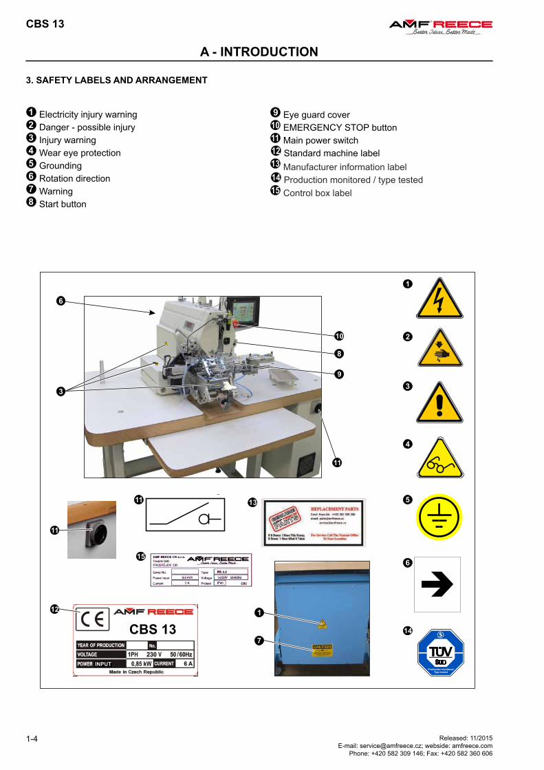
3. SAFETY LABELS AND ARRANGEMENT
Electricity injury warning Danger - possible injury Injury warning Wear eye protection Grounding Rotation direction Warning Start button
Eye guard cover EMERGENCY STOP button Main power switch Standard machine label Manufacturer information label Production monitored / type tested Control box label
CBS 13
1-5
A - INTRODUCTION
Released: 11/2015E-mail: [email protected]; webside: amfreece.comPhone: +420 582 309 146; Fax: +420 582 360 606
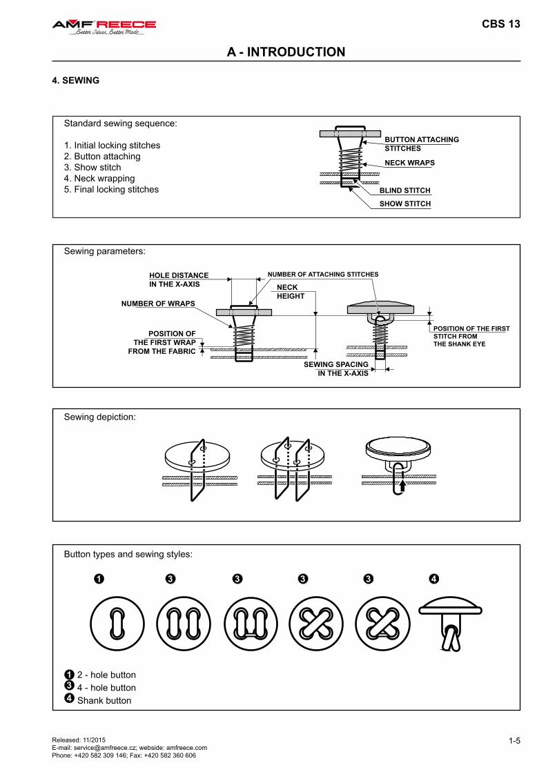
Standard sewing sequence:
1. Initial locking stitches2. Button attaching3. Show stitch4. Neck wrapping5. Final locking stitches
Sewing parameters:
Sewing depiction:
Button types and sewing styles:
4. SEWING
2 - hole button 4 - hole button Shank button
BUTTON ATTACHINGSTITCHES
NECK WRAPS
BLIND STITCH
SHOW STITCH
HOLE DISTANCEIN THE X-AXIS NECK
HEIGHT
NUMBER OF ATTACHING STITCHES
NUMBER OF WRAPS
POSITION OFTHE FIRST WRAP
FROM THE FABRIC
SEWING SPACINGIN THE X-AXIS
POSITION OF THE FIRST STITCH FROMTHE SHANK EYE
CBS 13
1-6 Released: 11/2015E-mail: [email protected]; webside: amfreece.com
Phone: +420 582 309 146; Fax: +420 582 360 606
A - INTRODUCTION
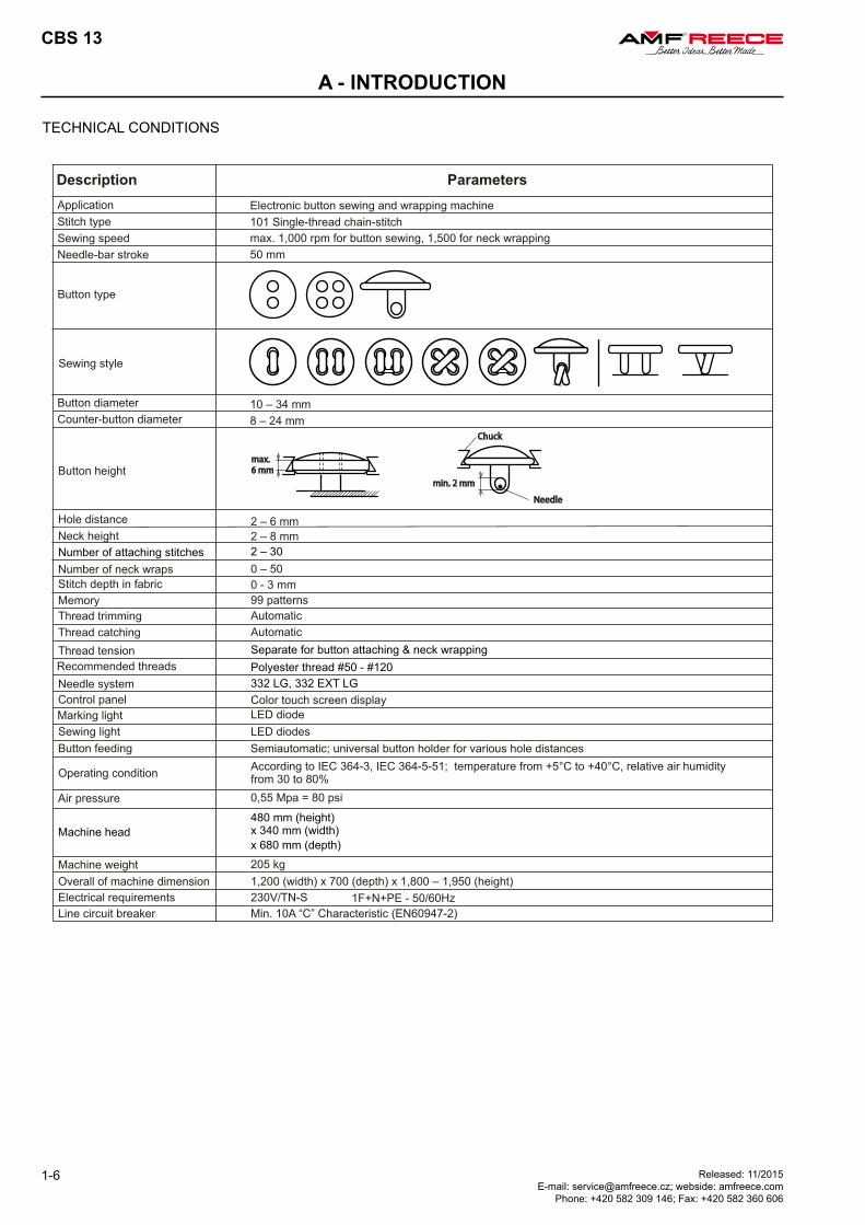
TECHNICAL CONDITIONS
CBS 13
1-7
A - INTRODUCTION
Released: 11/2015E-mail: [email protected]; webside: amfreece.comPhone: +420 582 309 146; Fax: +420 582 360 606
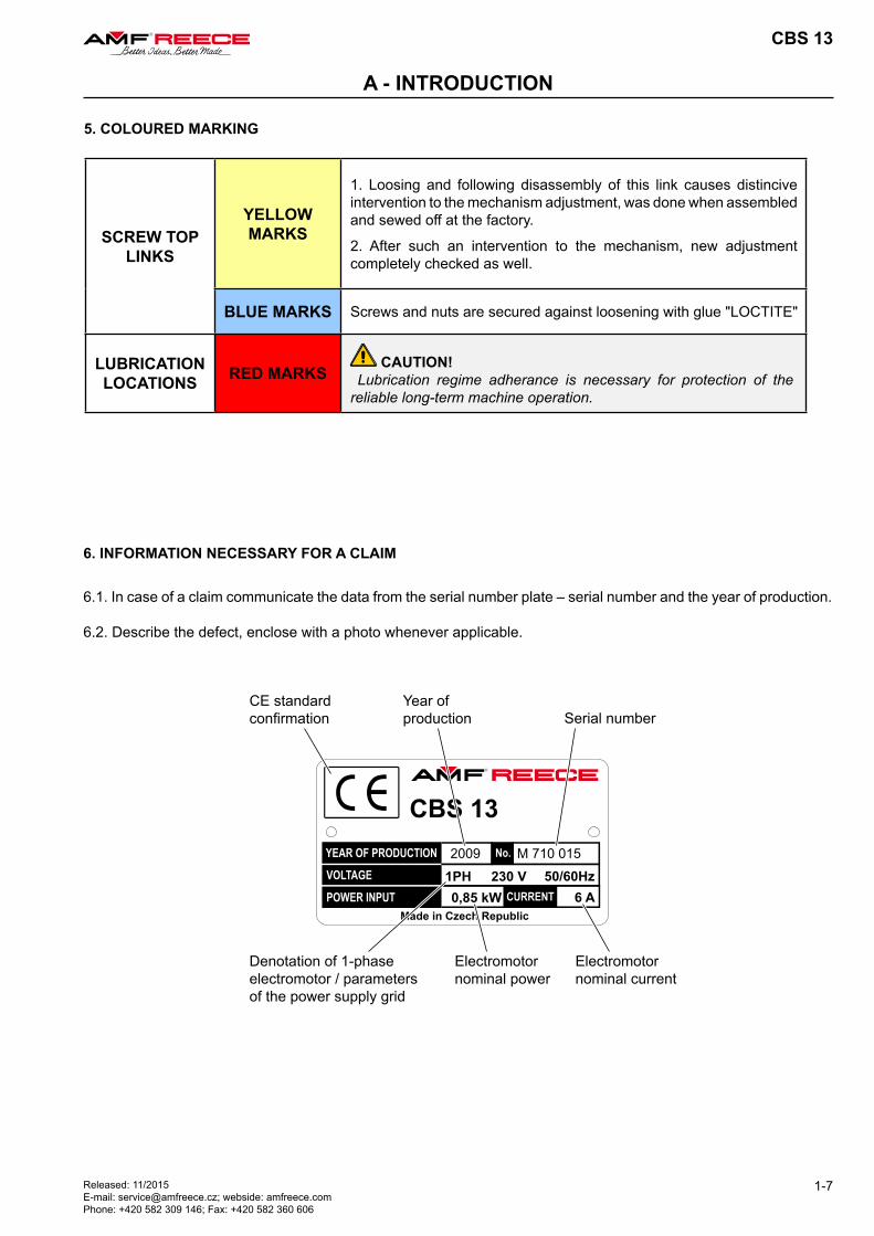
5. COLOURED MARKING
6. INFORMATION NECESSARY FOR A CLAIM
6.1. In case of a claim communicate the data from the serial number plate – serial number and the year of production.
6.2. Describe the defect, enclose with a photo whenever applicable.
CE standardconfirmation
Year ofproduction Serial number
Denotation of 1-phase electromotor / parameters of the power supply grid
Electromotor nominal power
Electromotor nominal current
SCREW TOP LINKS
YELLOW MARKS
1. Loosing and following disassembly of this link causes distincive intervention to the mechanism adjustment, was done when assembled and sewed off at the factory.
2. After such an intervention to the mechanism, new adjustment completely checked as well.
BLUE MARKS Screws and nuts are secured against loosening with glue "LOCTITE"
LUBRICATION LOCATIONS RED MARKS
CAUTION! Lubrication regime adherance is necessary for protection of the reliable long-term machine operation.
CBS 13
1-8 Released: 11/2015E-mail: [email protected]; webside: amfreece.com
Phone: +420 582 309 146; Fax: +420 582 360 606
A - INTRODUCTION
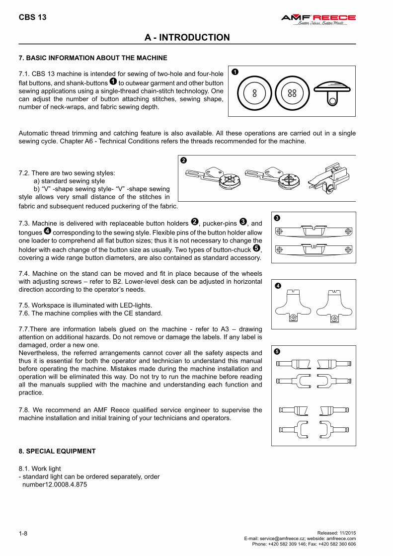
7. BASIC INFORMATION ABOUT THE MACHINE
7.1. CBS 13 machine is intended for sewing of two-hole and four-hole flat buttons, and shank-buttons to outwear garment and other button sewing applications using a single-thread chain-stitch technology. One can adjust the number of button attaching stitches, sewing shape, number of neck-wraps, and fabric sewing depth.
Automatic thread trimming and catching feature is also available. All these operations are carried out in a single sewing cycle. Chapter A6 - Technical Conditions refers the threads recommended for the machine.
7.2. There are two sewing styles: a) standard sewing style b) “V” -shape sewing style- “V” -shape sewing style allows very small distance of the stitches in fabric and subsequent reduced puckering of the fabric.
7.3. Machine is delivered with replaceable button holders , pucker-pins , and tongues corresponding to the sewing style. Flexible pins of the button holder allow one loader to comprehend all flat button sizes; thus it is not necessary to change the holder with each change of the button size as usually. Two types of button-chuck , covering a wide range button diameters, are also contained as standard accessory.
7.4. Machine on the stand can be moved and fit in place because of the wheels with adjusting screws – refer to B2. Lower-level desk can be adjusted in horizontal direction according to the operator’s needs.
7.5. Workspace is illuminated with LED-lights.7.6. The machine complies with the CE standard.
7.7.There are information labels glued on the machine - refer to A3 – drawing attention on additional hazards. Do not remove or damage the labels. If any label is damaged, order a new one.Nevertheless, the referred arrangements cannot cover all the safety aspects and thus it is essential for both the operator and technician to understand this manual before operating the machine. Mistakes made during the machine installation and operation will be eliminated this way. Do not try to run the machine before reading all the manuals supplied with the machine and understanding each function and practice.
7.8. We recommend an AMF Reece qualified service engineer to supervise the machine installation and initial training of your technicians and operators.
8. SPECIAL EQUIPMENT
8.1. Work light- standard light can be ordered separately, order number12.0008.4.875
CBS 13
1-9Released: 11/2015E-mail: [email protected]; webside: amfreece.com Phone: +420 582 309 146; Fax: +420 582 360 606
B - MACHINE ASSEMBLY
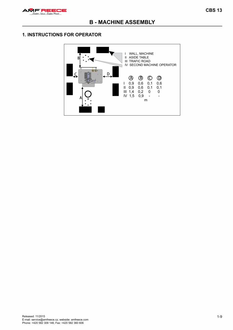
I WALL, MACHINEII ASIDE TABLEIII TRAFIC ROADIV SECOND MACHINE OPERATOR
1. INSTRUCTIONS FOR OPERATOR
CBS 13
1-10 Released: 11/2015 E-mail: [email protected]; webside: amfreece.com
Phone: +420 582 309 146; Fax: +420 582 360 606
B - MACHINE ASSEMBLY
2. CONNECTING THE MACHINE TO THE DISTRIBUTION OF ELECTRICITY AND AIR
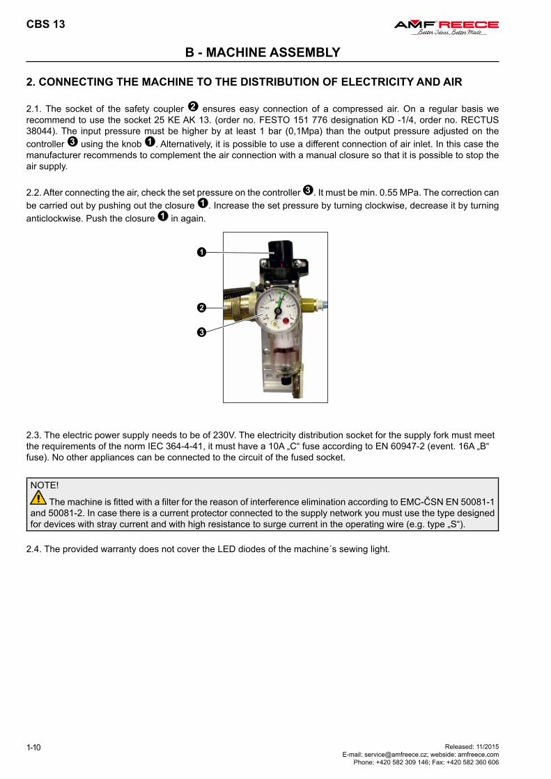
2.1. The socket of the safety coupler ensures easy connection of a compressed air. On a regular basis we recommend to use the socket 25 KE AK 13. (order no. FESTO 151 776 designation KD -1/4, order no. RECTUS 38044). The input pressure must be higher by at least 1 bar (0,1Mpa) than the output pressure adjusted on the controller using the knob . Alternatively, it is possible to use a different connection of air inlet. In this case the manufacturer recommends to complement the air connection with a manual closure so that it is possible to stop the air supply.
2.2. After connecting the air, check the set pressure on the controller . It must be min. 0.55 MPa. The correction can be carried out by pushing out the closure . Increase the set pressure by turning clockwise, decrease it by turning anticlockwise. Push the closure in again.
2.3. The electric power supply needs to be of 230V. The electricity distribution socket for the supply fork must meetthe requirements of the norm IEC 364-4-41, it must have a 10A „C“ fuse according to EN 60947-2 (event. 16A „B“fuse). No other appliances can be connected to the circuit of the fused socket.
NOTE!
The machine is fitted with a filter for the reason of interference elimination according to EMC-ČSN EN 50081-1and 50081-2. In case there is a current protector connected to the supply network you must use the type designedfor devices with stray current and with high resistance to surge current in the operating wire (e.g. type „S“).
2.4. The provided warranty does not cover the LED diodes of the machine´s sewing light.
4 3
1
2
2 13
4
CBS 13
1-11Released: 11/2015 E-mail: [email protected]; webside: amfreece.com Phone: +420 582 309 146; Fax: +420 582 360 606
C - PROPER APPLICATION
1. TURNING ON THE MACHINE - ESTABLISHMENT OF HOME POSITION
NOTE! Refer to section D for the comprehensive description of machine control through its display.
1.1. Before the first machine startup it is necessary to remove the preserving oil and grease all respective places asstated in chapter F 3.
1.2. Turn on the machine by rotating the main switch clockwise to position I ON.
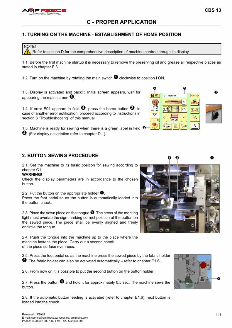
1.3. Display is activated and backlit. Initial screen appears, wait for appearing the main screen .
1.4. If error E01 appears in field , press the home button . In case of another error notification, proceed according to instructions in section 3 “Troubleshooting” of this manual.
1.5. Machine is ready for sewing when there is a green label in field . (For display description refer to chapter D 1).
2. BUTTON SEWING PROCEDURE
2.1. Set the machine to its basic position for sewing according to chapter C1 .WARNING!Check the display parameters are in accordance to the chosen button.
2.2. Put the button on the appropriate holder 1 .Press the foot pedal so as the button is automatically loaded into the button chuck.
2.3. Place the sewn piece on the tongue 2 . The cross of the marking light must overlap the sign marking correct position of the button on the sewed piece. The piece shall be evenly aligned and freely encircle the tongue.
2.4. Push the tongue into the machine up to the place where the machine fastens the piece. Carry out a second checkof the piece surface evenness.
2.5. Press the foot pedal so as the machine press the sewed piece by the fabric holder . The fabric holder can also be activated automatically – refer to chapter E1.6.
2.6. From now on it is possible to put the second button on the button holder.
2.7. Press the button and hold it for approximately 0.5 sec. The machine sews the button.
2.8. If the automatic button feeding is activated (refer to chapter E1.6), next button is loaded into the chuck.
CBS 13
1-12
C - PROPER APPLICATION
Released: 11/2015 E-mail: [email protected]; webside: amfreece.com
Phone: +420 582 309 146; Fax: +420 582 360 606
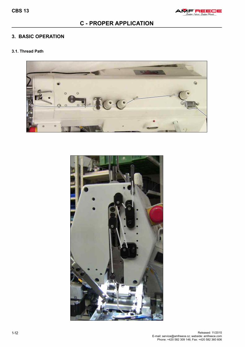
3.1. Thread Path
3. BASIC OPERATION
19
CBS 13
1-13Released: 11/2015 E-mail: [email protected]; webside: amfreece.com Phone: +420 582 309 146; Fax: +420 582 360 606
D - MACHINE CONTROLS
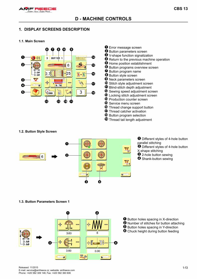
1.1. Main Screen1 Error message screen2 Button parameters screen3 V-shape function signalization4 Return to the previous machine operation5 Home position establishment6 Button programs overview screen7 Button program name8 Button style screen9 Neck parameters screen10 Stitch style adjustment screen11 Blind-stitch depth adjustment12 Sewing speed adjustment screen13 Locking stitch adjustment screen14 Production counter screen15 Service menu screen16 Thread change support button17 Thread catcher activation18 Button program selection19 Thread tail length adjustment
1 Different styles of 4-hole button parallel stitching2 Different styles of 4-hole button
X-shape stitching3 2-hole button sewing4 Shank-button sewing
1.2. Button Style Screen
1.3. Button Parameters Screen 1
1 Button holes spacing in X-direction2 Number of stitches for button attaching3 Button holes spacing in Y-direction4 Chuck height during button feeding
1. DISPLAY SCREENS DESCRIPTION
CBS 13
1-14
D - MACHINE CONTROLS
Released: 11/2015 E-mail: [email protected]; webside: amfreece.com
Phone: +420 582 309 146; Fax: +420 582 360 606
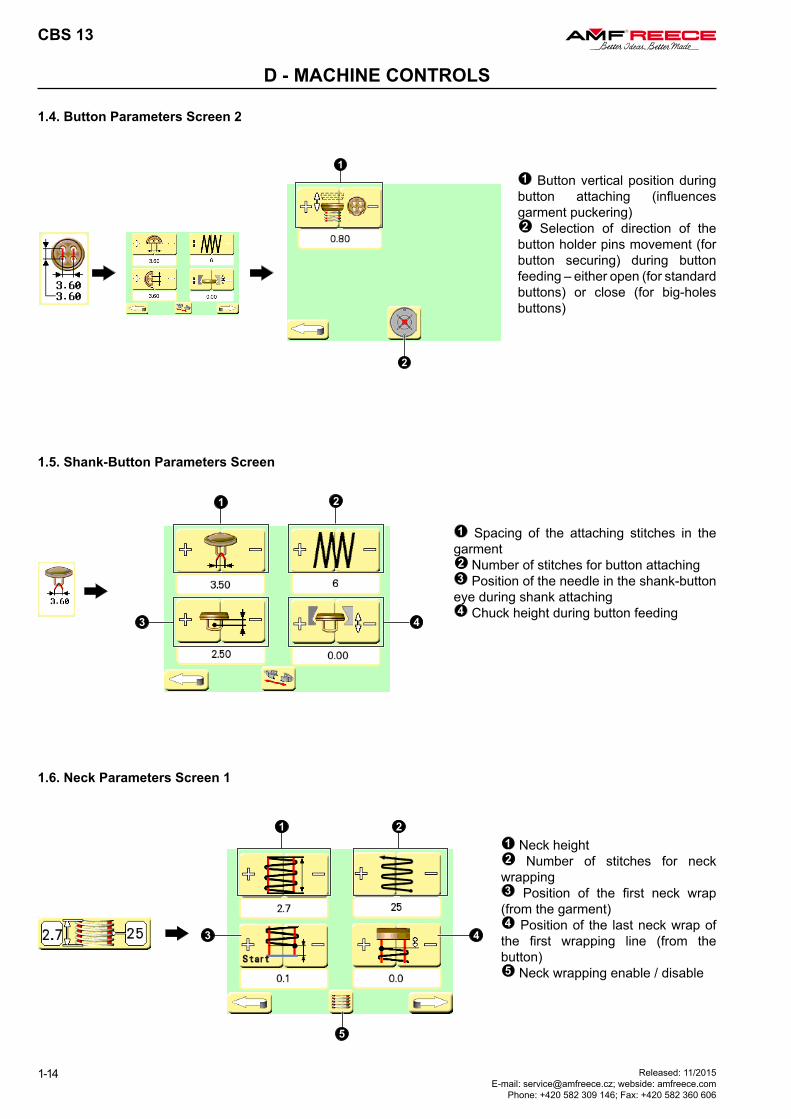
1.4. Button Parameters Screen 2
1 Button vertical position during button attaching (influences garment puckering)2 Selection of direction of the
button holder pins movement (for button securing) during button feeding – either open (for standard buttons) or close (for big-holes buttons)
1.6. Neck Parameters Screen 1
1 Neck height2 Number of stitches for neck
wrapping3 Position of the first neck wrap (from the garment)4 Position of the last neck wrap of
the first wrapping line (from the button)5 Neck wrapping enable / disable
1.5. Shank-Button Parameters Screen
1 Spacing of the attaching stitches in the garment2 Number of stitches for button attaching3 Position of the needle in the shank-button eye during shank attaching4 Chuck height during button feeding
4
CBS 13
1-15Released: 11/2015 E-mail: [email protected]; webside: amfreece.com Phone: +420 582 309 146; Fax: +420 582 360 606
D - MACHINE CONTROLS
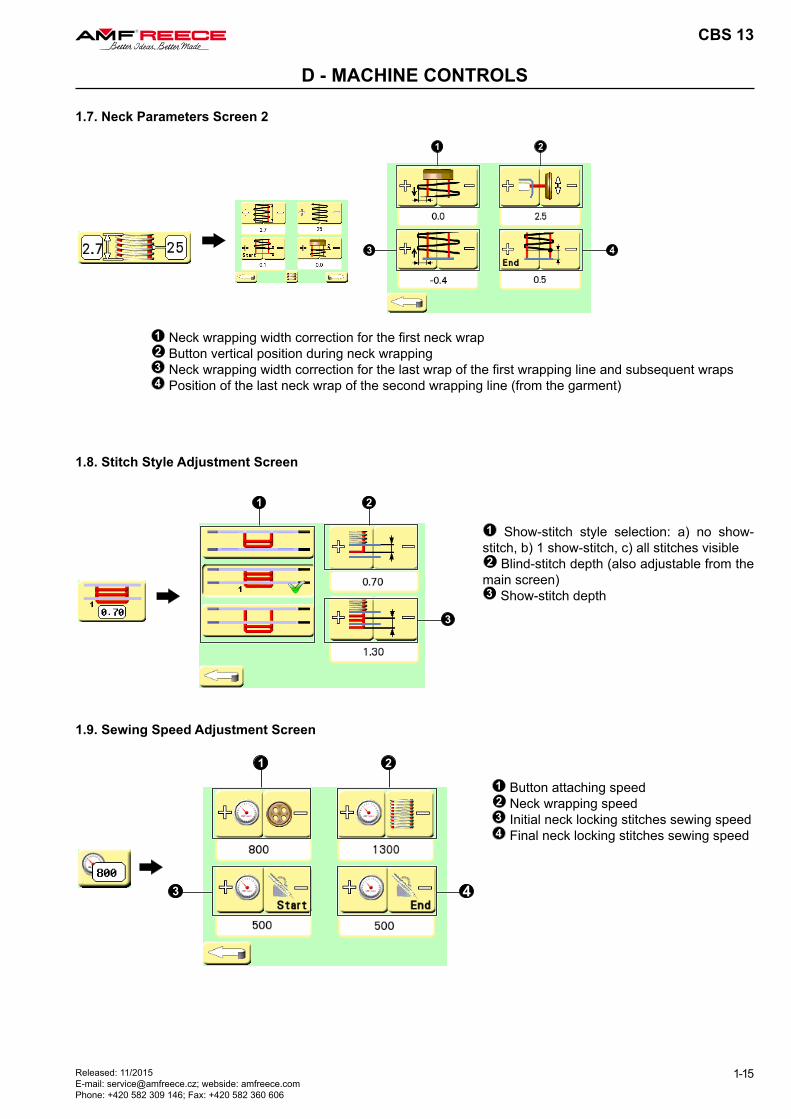
1.7. Neck Parameters Screen 2
1 Neck wrapping width correction for the first neck wrap2 Button vertical position during neck wrapping3 Neck wrapping width correction for the last wrap of the first wrapping line and subsequent wraps4 Position of the last neck wrap of the second wrapping line (from the garment)
1.8. Stitch Style Adjustment Screen
1 Show-stitch style selection: a) no show-stitch, b) 1 show-stitch, c) all stitches visible2 Blind-stitch depth (also adjustable from the
main screen)3 Show-stitch depth
1.9. Sewing Speed Adjustment Screen
1 Button attaching speed2 Neck wrapping speed3 Initial neck locking stitches sewing speed4 Final neck locking stitches sewing speed
2
4
5 6
CBS 13
1-16
D - MACHINE CONTROLS
Released: 11/2015 E-mail: [email protected]; webside: amfreece.com
Phone: +420 582 309 146; Fax: +420 582 360 606
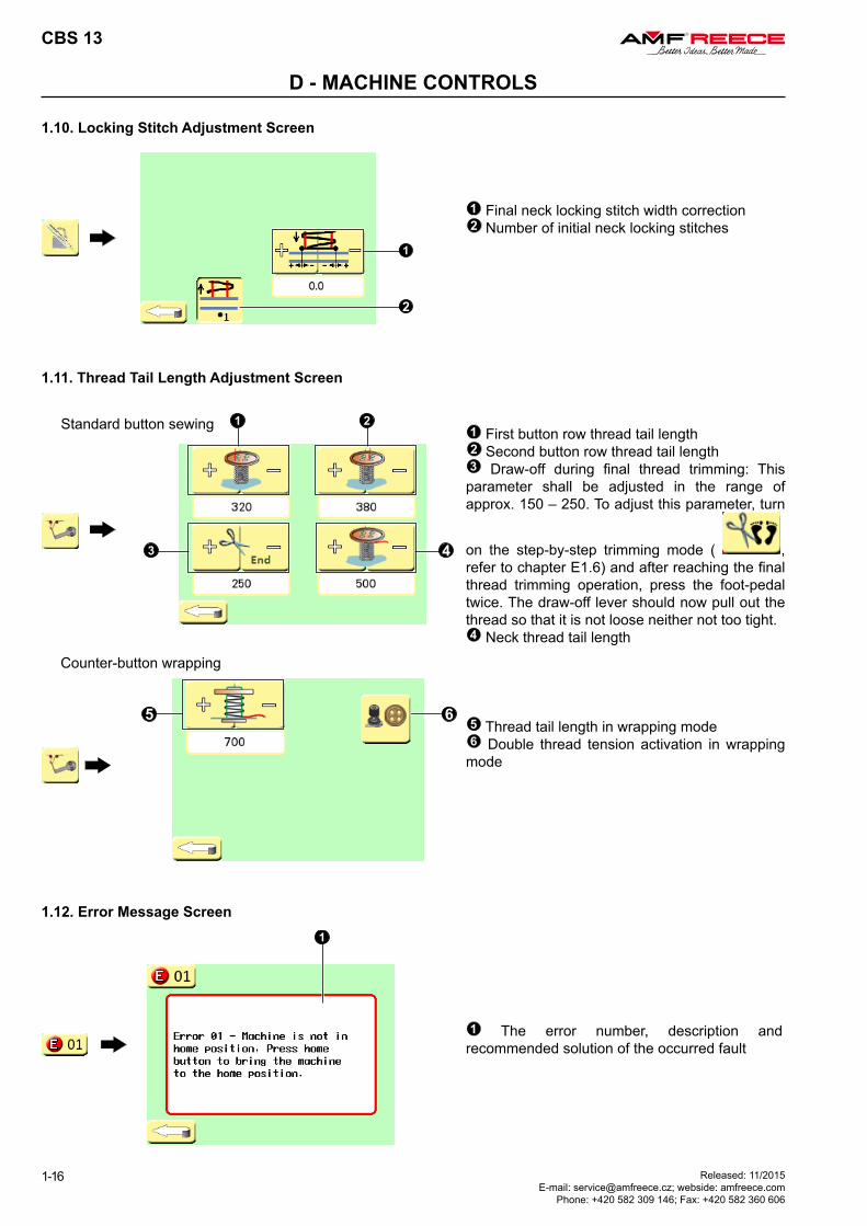
1.10. Locking Stitch Adjustment Screen
1 Final neck locking stitch width correction2 Number of initial neck locking stitches
1.12. Error Message Screen
1 The error number, description and recommended solution of the occurred fault
1.11. Thread Tail Length Adjustment Screen
1 First button row thread tail length2 Second button row thread tail length3 Draw-off during final thread trimming: This parameter shall be adjusted in the range of approx. 150 – 250. To adjust this parameter, turn
on the step-by-step trimming mode ( , refer to chapter E1.6) and after reaching the final thread trimming operation, press the foot-pedal twice. The draw-off lever should now pull out the thread so that it is not loose neither not too tight.4 Neck thread tail length
5 Thread tail length in wrapping mode6 Double thread tension activation in wrapping
mode
Standard button sewing
Counter-button wrapping
CBS 13
1-17Released: 11/2015 E-mail: [email protected]; webside: amfreece.com Phone: +420 582 309 146; Fax: +420 582 360 606
D - MACHINE CONTROLS
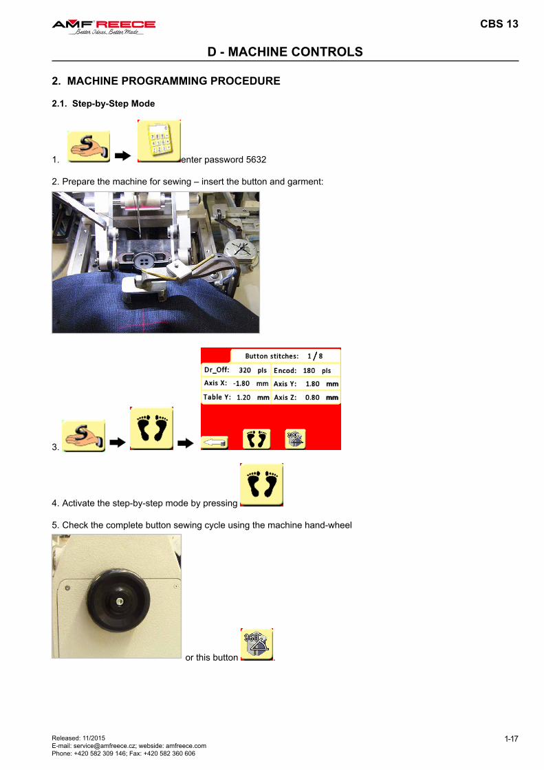
2. MACHINE PROGRAMMING PROCEDURE
2.1. Step-by-Step Mode
1. enter password 5632
2. Prepare the machine for sewing – insert the button and garment:
3.
4. Activate the step-by-step mode by pressing
5. Check the complete button sewing cycle using the machine hand-wheel
or this button .
CBS 13
1-18
D - MACHINE CONTROLS
Released: 11/2015 E-mail: [email protected]; webside: amfreece.com
Phone: +420 582 309 146; Fax: +420 582 360 606
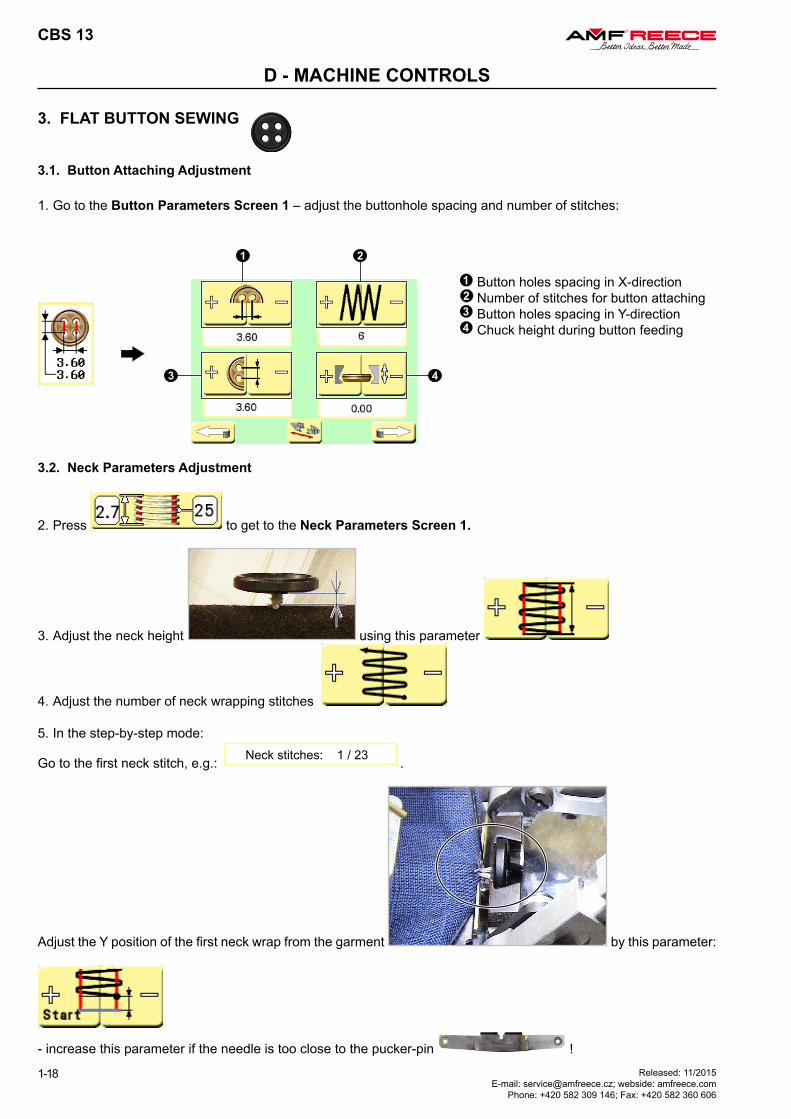
3. FLAT BUTTON SEWING
3.1. Button Attaching Adjustment
1. Go to the Button Parameters Screen 1 – adjust the buttonhole spacing and number of stitches:
3.2. Neck Parameters Adjustment
2. Press to get to the Neck Parameters Screen 1.
3. Adjust the neck height using this parameter
4. Adjust the number of neck wrapping stitches
5. In the step-by-step mode:
Go to the first neck stitch, e.g.: Neck stitches: 1 / 23 .
Adjust the Y position of the first neck wrap from the garment by this parameter:
- increase this parameter if the needle is too close to the pucker-pin !
1 Button holes spacing in X-direction2 Number of stitches for button attaching3 Button holes spacing in Y-direction4 Chuck height during button feeding
CBS 13
1-19Released: 11/2015 E-mail: [email protected]; webside: amfreece.com Phone: +420 582 309 146; Fax: +420 582 360 606
D - MACHINE CONTROLS
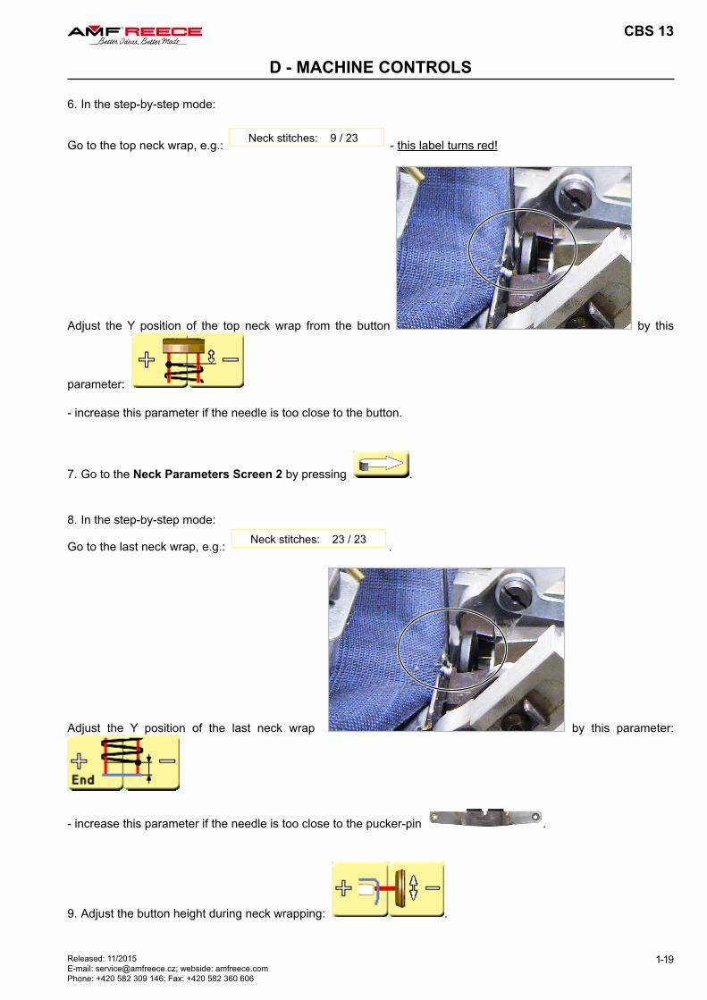
6. In the step-by-step mode:
Go to the top neck wrap, e.g.: Neck stitches: 9 / 23 - this label turns red!
Adjust the Y position of the top neck wrap from the button by this
parameter:
- increase this parameter if the needle is too close to the button.
7. Go to the Neck Parameters Screen 2 by pressing .
8. In the step-by-step mode:
Go to the last neck wrap, e.g.: Neck stitches: 23 / 23 .
Adjust the Y position of the last neck wrap by this parameter:
- increase this parameter if the needle is too close to the pucker-pin .
9. Adjust the button height during neck wrapping: .
CBS 13
1-20
D - MACHINE CONTROLS
Released: 11/2015 E-mail: [email protected]; webside: amfreece.com
Phone: +420 582 309 146; Fax: +420 582 360 606
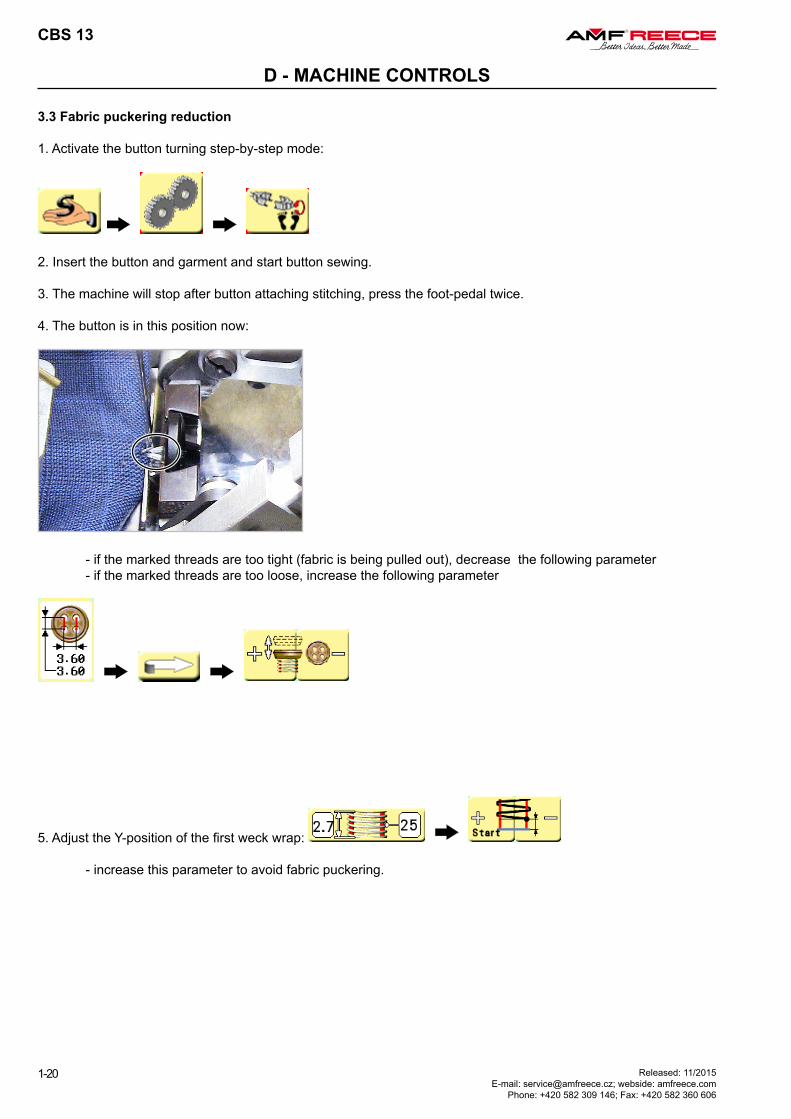
3.3 Fabric puckering reduction
1. Activate the button turning step-by-step mode:
2. Insert the button and garment and start button sewing.
3. The machine will stop after button attaching stitching, press the foot-pedal twice.
4. The button is in this position now:
- if the marked threads are too tight (fabric is being pulled out), decrease the following parameter - if the marked threads are too loose, increase the following parameter
5. Adjust the Y-position of the first weck wrap:
- increase this parameter to avoid fabric puckering.
CBS 13
1-21Released: 11/2015 E-mail: [email protected]; webside: amfreece.com Phone: +420 582 309 146; Fax: +420 582 360 606
D - MACHINE CONTROLS
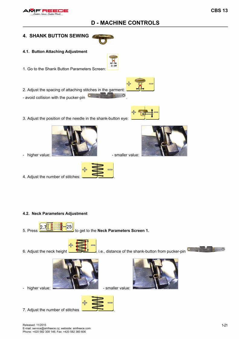
4. SHANK BUTTON SEWING
4.1. Button Attaching Adjustment
1. Go to the Shank Button Parameters Screen:
2. Adjust the spacing of attaching stitches in the garment:
- avoid collision with the pucker-pin .
3. Adjust the position of the needle in the shank-button eye:
- higher value: - smaller value:
4. Adjust the number of stitches: .
4.2. Neck Parameters Adjustment
5. Press to get to the Neck Parameters Screen 1.
6. Adjust the neck height , i.e., distance of the shank-button from pucker-pin
- higher value: - smaller value:
7. Adjust the number of stitches .

CBS 13
1-22
D - MACHINE CONTROLS
Released: 11/2015 E-mail: [email protected]; webside: amfreece.com
Phone: +420 582 309 146; Fax: +420 582 360 606
5. ALL BUTTONS SEWING
5.1. Depth of Sewing Adjustment
1. Go to the Stitch Style Adjustment Screen: .
2. Adjust the depth of sewing for blind stitches: .
3. Adjust the depth of sewing for show-stitch: - this is an increment to the blind stitch depth.
5.2. Thread Tail Length Adjustment
1. Go to the Thread Tail Length Adjustment Screen:
2. Adjust draw-off during final thread trimming : This parameter shall be adjusted in the range of
approx. 150 – 250. To adjust this parameter, turn on the step-by-step trimming mode ( , refer to chapter E1.6) and after reaching the final thread trimming operation, press the foot-pedal twice. The draw-off lever should now pull out the thread so that it is not loose neither not too tight.
3. Adjust remaining thread tails length.
8. In the step-by-step mode:
Go to the first neck stitch, e.g. Neck stitches: 1 / 9 :
Adjust the Y position of the neck wrap from the garment:
- increase this parameter if the needle is too close to the pucker-pin
- decrease this parameter if the needle is too close to the shank-button eye
9. Go to the Neck Parameters Screen 2 by pressing .
10. Adjust the button height during neck wrapping: .
11
12
CBS 13
1-23Released: 11/2015 E-mail: [email protected]; webside: amfreece.com Phone: +420 582 309 146; Fax: +420 582 360 606
E - STANDARD MACHINE ADJUSTMENT
1. SERVICE MENU SCREEN
1.1. Service Menu Screen
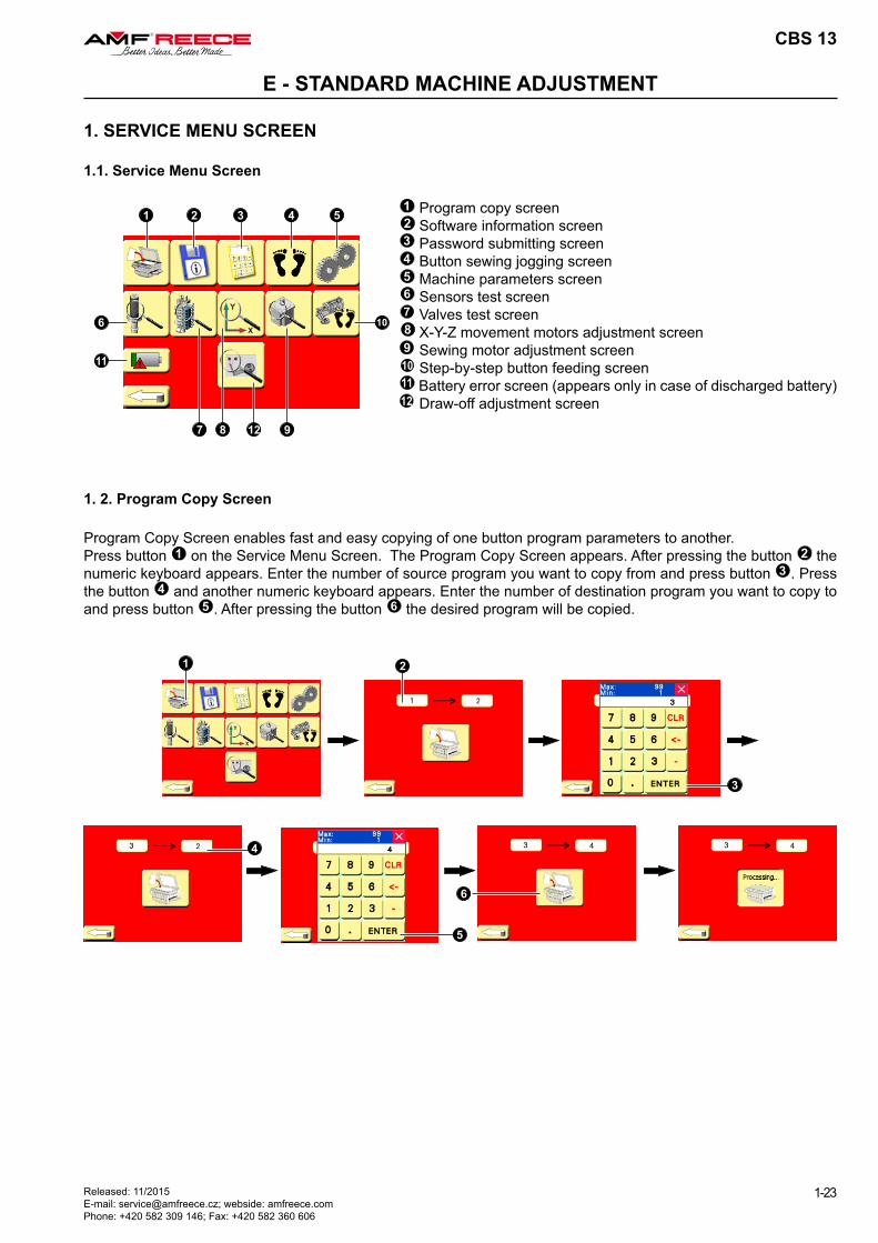
1 Program copy screen2 Software information screen3 Password submitting screen4 Button sewing jogging screen5 Machine parameters screen6 Sensors test screen7 Valves test screen8 X-Y-Z movement motors adjustment screen9 Sewing motor adjustment screen10 Step-by-step button feeding screen11 Battery error screen (appears only in case of discharged battery)12 Draw-off adjustment screen
1. 2. Program Copy Screen
Program Copy Screen enables fast and easy copying of one button program parameters to another.Press button 1 on the Service Menu Screen. The Program Copy Screen appears. After pressing the button 2 the numeric keyboard appears. Enter the number of source program you want to copy from and press button 3 . Press the button 4 and another numeric keyboard appears. Enter the number of destination program you want to copy to and press button 5 . After pressing the button 6 the desired program will be copied.
CBS 13
1-24 Released: 11/2015 E-mail: [email protected]; webside: amfreece.com
Phone: +420 582 309 146; Fax: +420 582 360 606
E - STANDARD MACHINE ADJUSTMENT
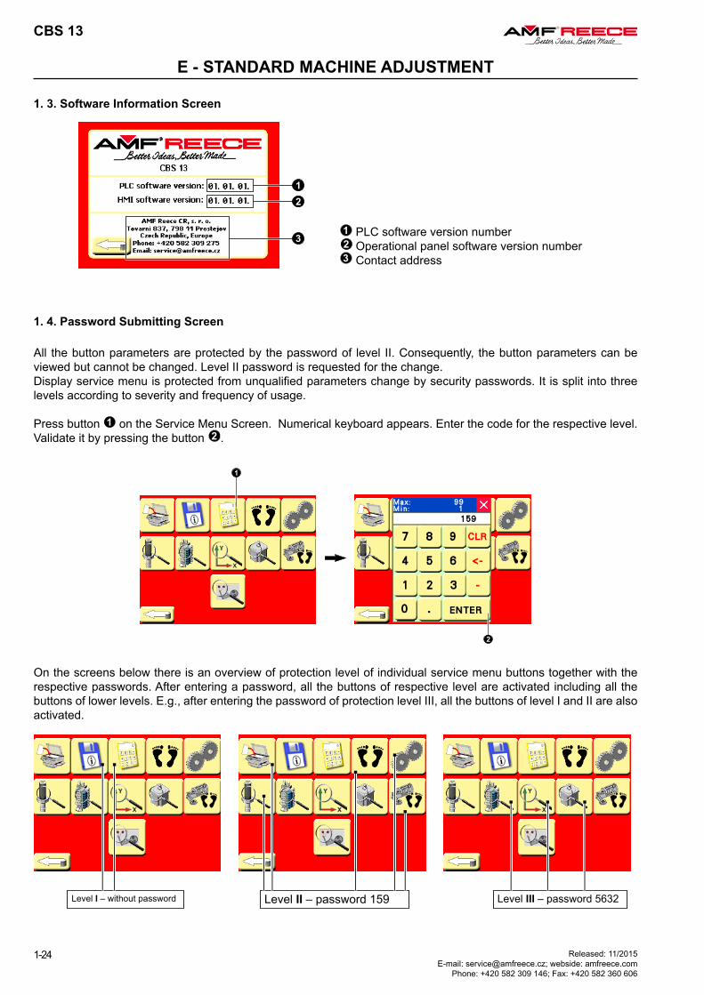
1. 3. Software Information Screen
1 PLC software version number2 Operational panel software version number3 Contact address
1. 4. Password Submitting Screen
All the button parameters are protected by the password of level II. Consequently, the button parameters can be viewed but cannot be changed. Level II password is requested for the change. Display service menu is protected from unqualified parameters change by security passwords. It is split into three levels according to severity and frequency of usage.
Press button 1 on the Service Menu Screen. Numerical keyboard appears. Enter the code for the respective level. Validate it by pressing the button 2 .
On the screens below there is an overview of protection level of individual service menu buttons together with the respective passwords. After entering a password, all the buttons of respective level are activated including all the buttons of lower levels. E.g., after entering the password of protection level III, all the buttons of level I and II are also activated.
Level I – without password Level II – password 159 Level III – password 5632
14
CBS 13
1-25Released: 11/2015 E-mail: [email protected]; webside: amfreece.com Phone: +420 582 309 146; Fax: +420 582 360 606
E - STANDARD MACHINE ADJUSTMENT
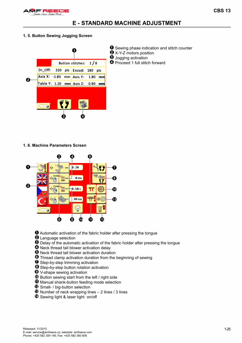
1. 5. Button Sewing Jogging Screen
1 Sewing phase indication and stitch counter2 X-Y-Z motors position3 Jogging activation4 Proceed 1 full stitch forward
1. 6. Machine Parameters Screen
1 Automatic activation of the fabric holder after pressing the tongue2 Language selection3 Delay of the automatic activation of the fabric holder after pressing the tongue4 Neck thread tail blower activation delay5 Neck thread tail blower activation duration6 Thread clamp activation duration from the beginning of sewing 7 Step-by-step trimming activation8 Step-by-step button rotation activation9 V-shape sewing activation10 Button sewing start from the left / right side11 Manual shank-button feeding mode selection12 Small- / big-button selection13 Number of neck wrapping lines – 2 lines / 3 lines14 Sewing light & laser light on/off
12
10 11
CBS 13
1-26 Released: 11/2015 E-mail: [email protected]; webside: amfreece.com
Phone: +420 582 309 146; Fax: +420 582 360 606
E - STANDARD MACHINE ADJUSTMENT
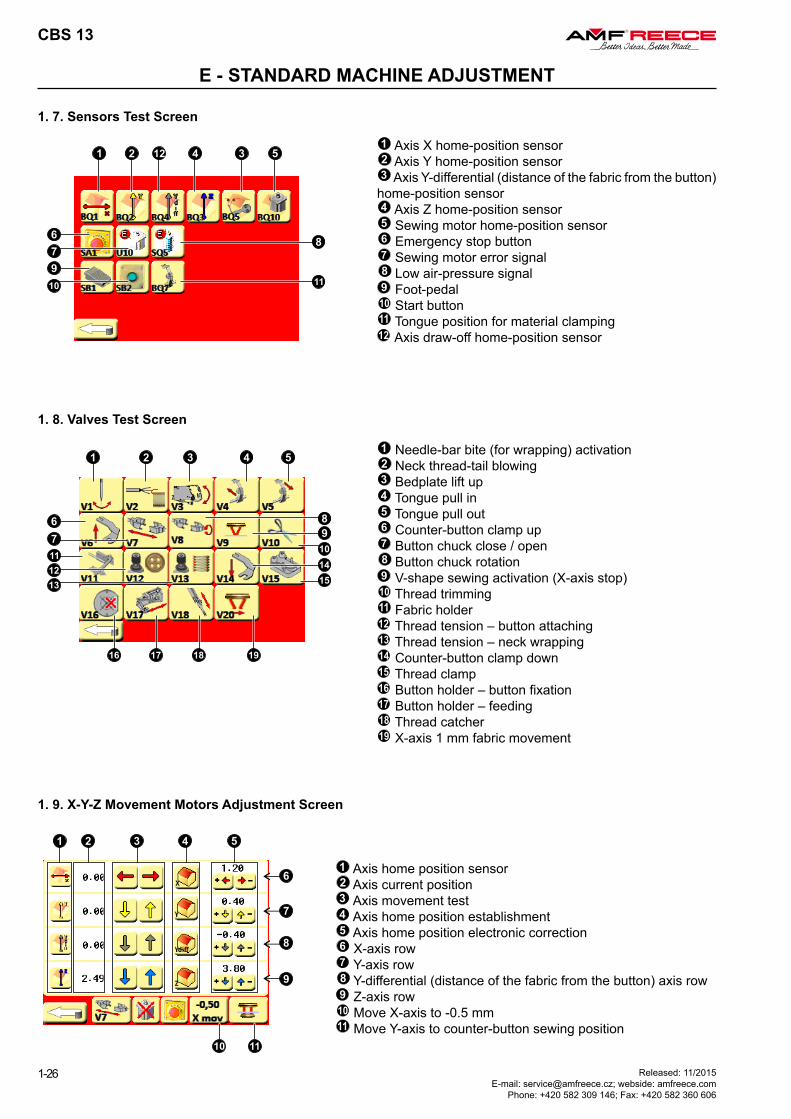
1. 7. Sensors Test Screen
1 Axis X home-position sensor2 Axis Y home-position sensor3 Axis Y-differential (distance of the fabric from the button) home-position sensor4 Axis Z home-position sensor5 Sewing motor home-position sensor6 Emergency stop button7 Sewing motor error signal8 Low air-pressure signal9 Foot-pedal10 Start button11 Tongue position for material clamping12 Axis draw-off home-position sensor
1. 8. Valves Test Screen
1 Needle-bar bite (for wrapping) activation2 Neck thread-tail blowing3 Bedplate lift up4 Tongue pull in5 Tongue pull out6 Counter-button clamp up7 Button chuck close / open8 Button chuck rotation9 V-shape sewing activation (X-axis stop)10 Thread trimming11 Fabric holder12 Thread tension – button attaching13 Thread tension – neck wrapping14 Counter-button clamp down15 Thread clamp16 Button holder – button fixation17 Button holder – feeding18 Thread catcher19 X-axis 1 mm fabric movement
1. 9. X-Y-Z Movement Motors Adjustment Screen
1 Axis home position sensor2 Axis current position3 Axis movement test4 Axis home position establishment5 Axis home position electronic correction6 X-axis row7 Y-axis row8 Y-differential (distance of the fabric from the button) axis row9 Z-axis row10 Move X-axis to -0.5 mm11 Move Y-axis to counter-button sewing position
CBS 13
1-27Released: 11/2015 E-mail: [email protected]; webside: amfreece.com Phone: +420 582 309 146; Fax: +420 582 360 606
E - STANDARD MACHINE ADJUSTMENT
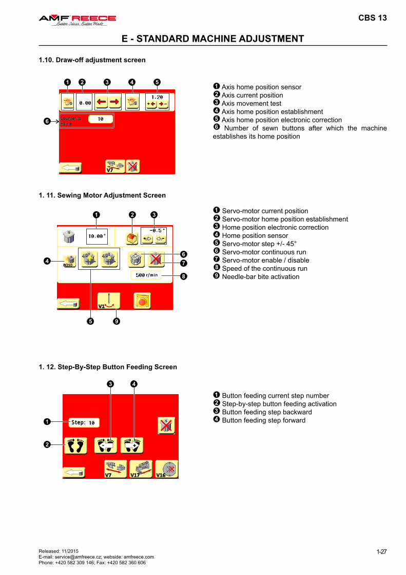
1. 11. Sewing Motor Adjustment Screen
1 Servo-motor current position2 Servo-motor home position establishment3 Home position electronic correction4 Home position sensor5 Servo-motor step +/- 45°6 Servo-motor continuous run7 Servo-motor enable / disable8 Speed of the continuous run9 Needle-bar bite activation
1. 12. Step-By-Step Button Feeding Screen
1 Button feeding current step number2 Step-by-step button feeding activation3 Button feeding step backward4 Button feeding step forward
1.10. Draw-off adjustment screen
1 Axis home position sensor2 Axis current position3 Axis movement test4 Axis home position establishment5 Axis home position electronic correction6 Number of sewn buttons after which the machine
establishes its home position
CBS 13
1-28 Released: 11/2015 E-mail: [email protected]; webside: amfreece.com
Phone: +420 582 309 146; Fax: +420 582 360 606
E - STANDARD MACHINE ADJUSTMENT
2. SEWING MECHANISMS ADJUSTMENTThe adjustments described in this chapter must be performed in the same order as described herein.
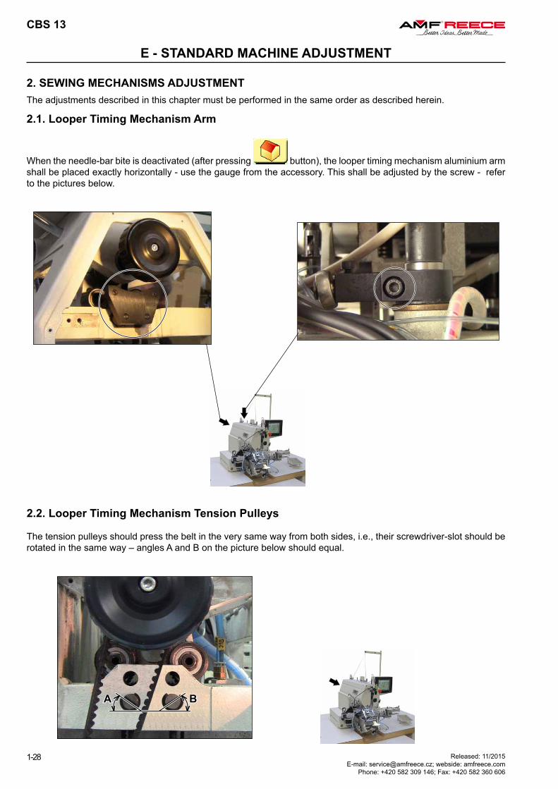
2.2. Looper Timing Mechanism Tension Pulleys
The tension pulleys should press the belt in the very same way from both sides, i.e., their screwdriver-slot should be rotated in the same way – angles A and B on the picture below should equal.
2.1. Looper Timing Mechanism Arm
When the needle-bar bite is deactivated (after pressing button), the looper timing mechanism aluminium arm shall be placed exactly horizontally - use the gauge from the accessory. This shall be adjusted by the screw - refer to the pictures below.
THROAT-PLATE
FRONT-BACKNEEDLE
THROAT-PLATE
LEFT-RIGHT
NEEDLE
CBS 13
1-29Released: 11/2015 E-mail: [email protected]; webside: amfreece.com Phone: +420 582 309 146; Fax: +420 582 360 606
E - STANDARD MACHINE ADJUSTMENT
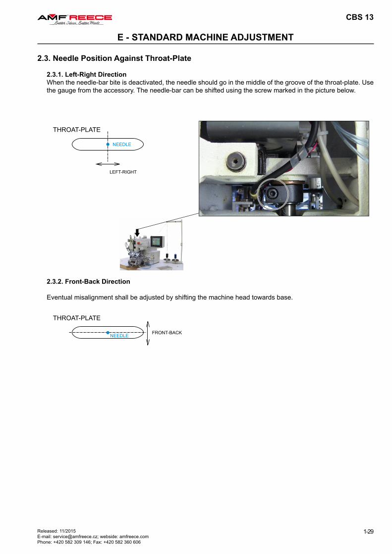
2.3. Needle Position Against Throat-Plate
2.3.1. Left-Right Direction When the needle-bar bite is deactivated, the needle should go in the middle of the groove of the throat-plate. Use the gauge from the accessory. The needle-bar can be shifted using the screw marked in the picture below.
2.3.2. Front-Back Direction
Eventual misalignment shall be adjusted by shifting the machine head towards base.
CBS 13
1-30 Released: 11/2015 E-mail: [email protected]; webside: amfreece.com
Phone: +420 582 309 146; Fax: +420 582 360 606
E - STANDARD MACHINE ADJUSTMENT
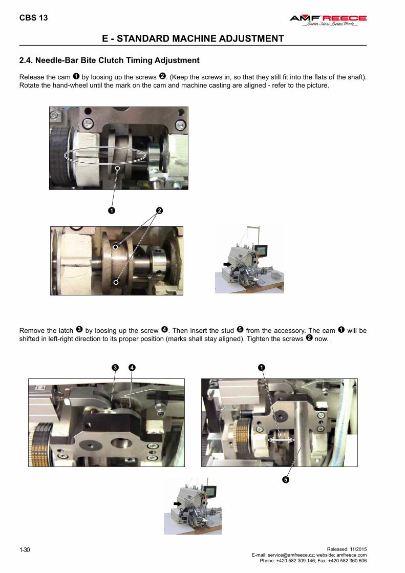
2.4. Needle-Bar Bite Clutch Timing Adjustment
Release the cam 1 by loosing up the screws 2 . (Keep the screws in, so that they still fit into the flats of the shaft). Rotate the hand-wheel until the mark on the cam and machine casting are aligned - refer to the picture.
Remove the latch 3 by loosing up the screw 4 . Then insert the stud 5 from the accessory. The cam 1 will be shifted in left-right direction to its proper position (marks shall stay aligned). Tighten the screws 2 now.
CBS 13
1-31Released: 11/2015 E-mail: [email protected]; webside: amfreece.com Phone: +420 582 309 146; Fax: +420 582 360 606
E - STANDARD MACHINE ADJUSTMENT
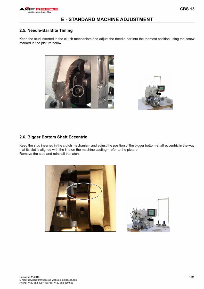
2.5. Needle-Bar Bite Timing
Keep the stud inserted in the clutch mechanism and adjust the needle-bar into the topmost position using the screw marked in the picture below.
2.6. Bigger Bottom Shaft Eccentric
Keep the stud inserted in the clutch mechanism and adjust the position of the bigger bottom-shaft eccentric in the way that its slot is aligned with the line on the machine casting - refer to the picture.Remove the stud and reinstall the latch.
x
x
CBS 13
1-32 Released: 11/2015 E-mail: [email protected]; webside: amfreece.com
Phone: +420 582 309 146; Fax: +420 582 360 606
E - STANDARD MACHINE ADJUSTMENT
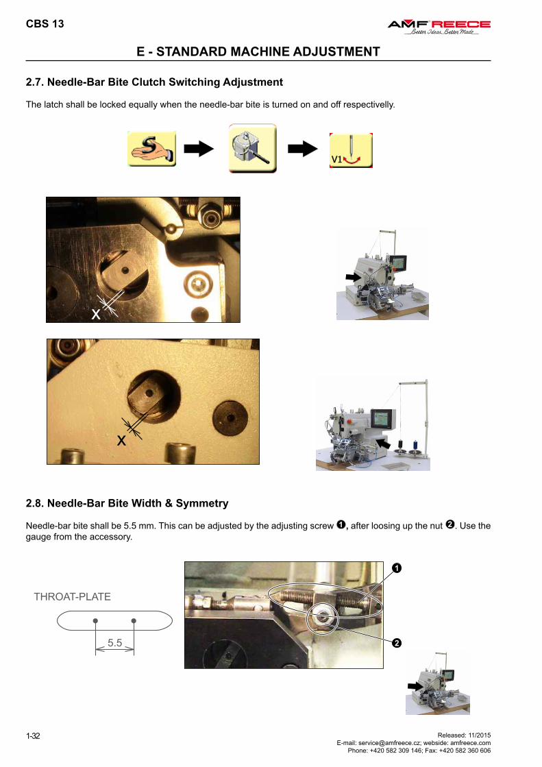
2.7. Needle-Bar Bite Clutch Switching Adjustment
The latch shall be locked equally when the needle-bar bite is turned on and off respectivelly.
2.8. Needle-Bar Bite Width & Symmetry
Needle-bar bite shall be 5.5 mm. This can be adjusted by the adjusting screw 1 , after loosing up the nut 2 . Use the gauge from the accessory.
CBS 13
1-33Released: 11/2015 E-mail: [email protected]; webside: amfreece.com Phone: +420 582 309 146; Fax: +420 582 360 606
E - STANDARD MACHINE ADJUSTMENT
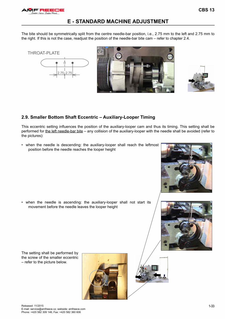
The bite should be symmetrically split from the centre needle-bar position, i.e., 2.75 mm to the left and 2.75 mm to the right. If this is not the case, readjust the position of the needle-bar bite cam – refer to chapter 2.4.
2.9. Smaller Bottom Shaft Eccentric – Auxiliary-Looper Timing
This eccentric setting influences the position of the auxiliary-looper cam and thus its timing. This setting shall be performed for the left needle-bar bite – any collision of the auxiliary-looper with the needle shall be avoided (refer to the pictures):
• when the needle is ascending: the auxiliary-looper shall not start its movement before the needle leaves the looper height
• when the needle is descending: the auxiliary-looper shall reach the leftmost position before the needle reaches the looper height
The setting shall be performed by the screw of the smaller eccentric – refer to the picture below.
NEEDLE
AUXILIARYLOOPER
1mm
PRINCIPALLOOPER
NEEDLE
0-0.1mm
PRINCIPALLOOPER
NEEDLE
1mm
CBS 13
1-34 Released: 11/2015 E-mail: [email protected]; webside: amfreece.com
Phone: +420 582 309 146; Fax: +420 582 360 606
E - STANDARD MACHINE ADJUSTMENT
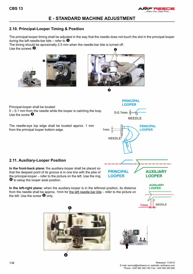
2.10. Principal-Looper Timing & Position
The principal-looper timing shall be adjusted in the way that the needle does not touch the slot in the principal-looper during the left needle-bar bite – refer to 1 .The timing should be aproximatly 2.5 mm when the needle-bar bite is turned off.Use the screws 2 .
In the left-right plane: when the auxiliary-looper is in the leftmost position, its distance from the needle shall be approx. 1mm for the left needle-bar bite – refer to the picture on the left. Use the screw 5 only.
Principal-looper shall be located 0 – 0.1 mm from the needle while the looper is catching the loop.Use the screw 3 .
2.11. Auxiliary-Looper Position
In the front-back plane: the auxiliary-looper shall be placed so that the deepest point of its groove is in one line with the pike of the principal-looper – refer to the picture on the left. Use the ring 4 to setup the looper axial position.
The needle-eye top edge shall be located approx. 1 mm from the principal looper bottom edge.

CBS 13
1-35Released: 11/2015 E-mail: [email protected]; webside: amfreece.com Phone: +420 582 309 146; Fax: +420 582 360 606
E - STANDARD MACHINE ADJUSTMENT
2.12. Sewing Servo-Motor Home Position
The home position of the sewing servo-motor is adjusted by the position of the ring – refer to the picture. After establishing the servo-motor home position, the marks on the cam and machine casting should be aligned and the needle-bar just starting the right bite.
2.13. Opening Thread-Tension CamThe cam shall be adjusted so that its guideline is in the top position when the needle-bar is also in the topmost position – refer to the picture.

2.5 mm
CBS 13
1-36 Released: 11/2015 E-mail: [email protected]; webside: amfreece.com
Phone: +420 582 309 146; Fax: +420 582 360 606
E - STANDARD MACHINE ADJUSTMENT
3. HOME-POSITION RAW ADJUSTMENT
3.1. X-Axis Height
Adjust the height of X-axis mechanism using the marked screws to reach the clearance of 2.5 mm.
3.3. X-Axis Home Position
Use the X-axis home sensor / its shutter and the electronic correction to adjust the home position of X-axis (refer to the picture). Insert the
gauge – the needle shall go exactly into the centre hole in the left-right direction.
3.4. Bedplate X-Axis Position
Using the screws marked in the picture, adjust the bedplate position into the depicted state.
3.2. Home Sensors Clearance
All the home-position sensors (sewing servo-motor, X-axis, Y-axis, Y-differential-axis, and Z-axis) shall be adjusted according to the picture below, i.e., they should be located approx. 0.3 mm in the axial direction from their respective metal-shutters.
After each adjustment press button to re-establish a home position.
CBS 13
1-37Released: 11/2015 E-mail: [email protected]; webside: amfreece.com Phone: +420 582 309 146; Fax: +420 582 360 606
E - STANDARD MACHINE ADJUSTMENT
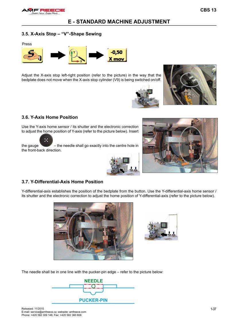
3.5. X-Axis Stop – “V”-Shape Sewing
3.6. Y-Axis Home Position
Use the Y-axis home sensor / its shutter and the electronic correction to adjust the home position of Y-axis (refer to the picture below). Insert
the gauge – the needle shall go exactly into the centre hole in the front-back direction.
Press
Adjust the X-axis stop left-right position (refer to the picture) in the way that the bedplate does not move when the X-axis stop cylinder (V9) is being switched on/off.
3.7. Y-Differential-Axis Home Position
Y-differential-axis establishes the position of the bedplate from the button. Use the Y-differential-axis home sensor / its shutter and the electronic correction to adjust the home position of Y-differential-axis (refer to the picture below).
The needle shall be in one line with the pucker-pin edge – refer to the picture below:
CBS 13
1-38 Released: 11/2015 E-mail: [email protected]; webside: amfreece.com
Phone: +420 582 309 146; Fax: +420 582 360 606
E - STANDARD MACHINE ADJUSTMENT
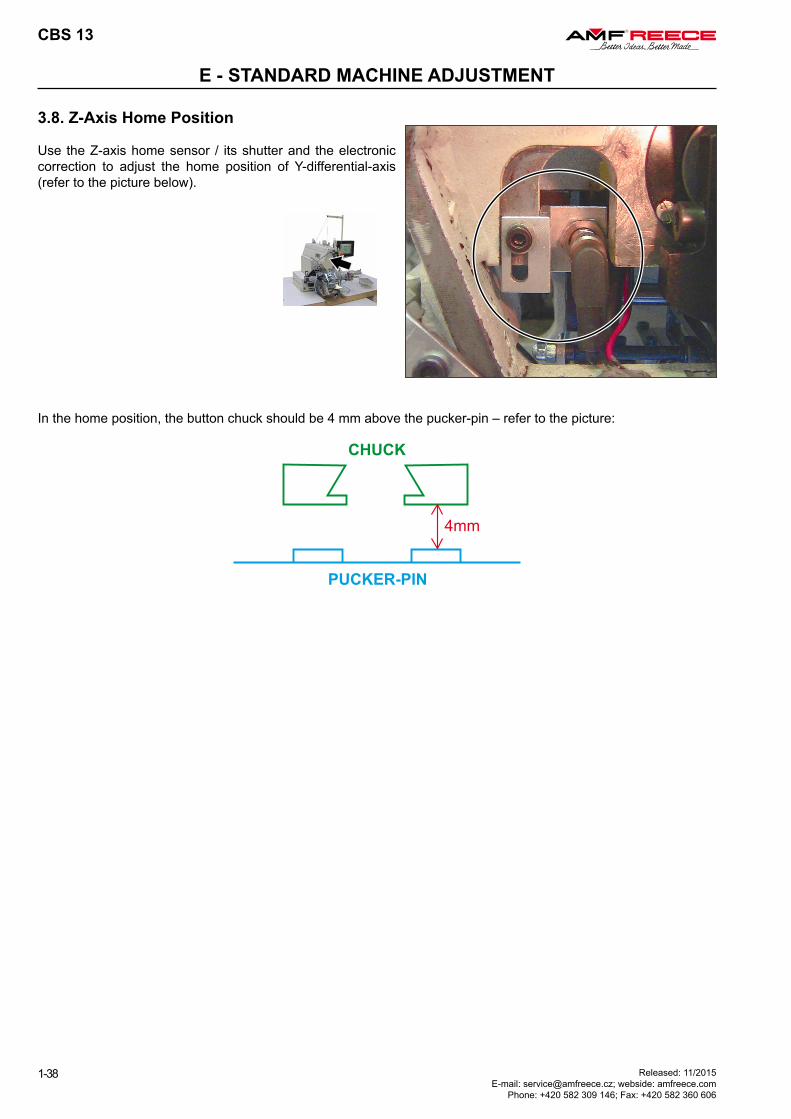
3.8. Z-Axis Home Position
Use the Z-axis home sensor / its shutter and the electronic correction to adjust the home position of Y-differential-axis (refer to the picture below).
In the home position, the button chuck should be 4 mm above the pucker-pin – refer to the picture:
CBS 13
1-39Released: 11/2015 E-mail: [email protected]; webside: amfreece.com Phone: +420 582 309 146; Fax: +420 582 360 606
E - STANDARD MACHINE ADJUSTMENT
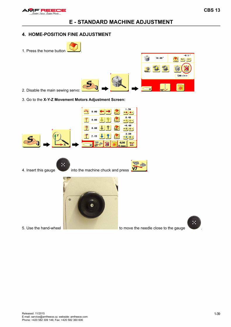
4. HOME-POSITION FINE ADJUSTMENT
1. Press the home button .
2. Disable the main sewing servo:
3. Go to the X-Y-Z Movement Motors Adjustment Screen:
4. Insert this gauge into the machine chuck and press .
5. Use the hand-wheel to move the needle close to the gauge .
CBS 13
1-40 Released: 11/2015 E-mail: [email protected]; webside: amfreece.com
Phone: +420 582 309 146; Fax: +420 582 360 606
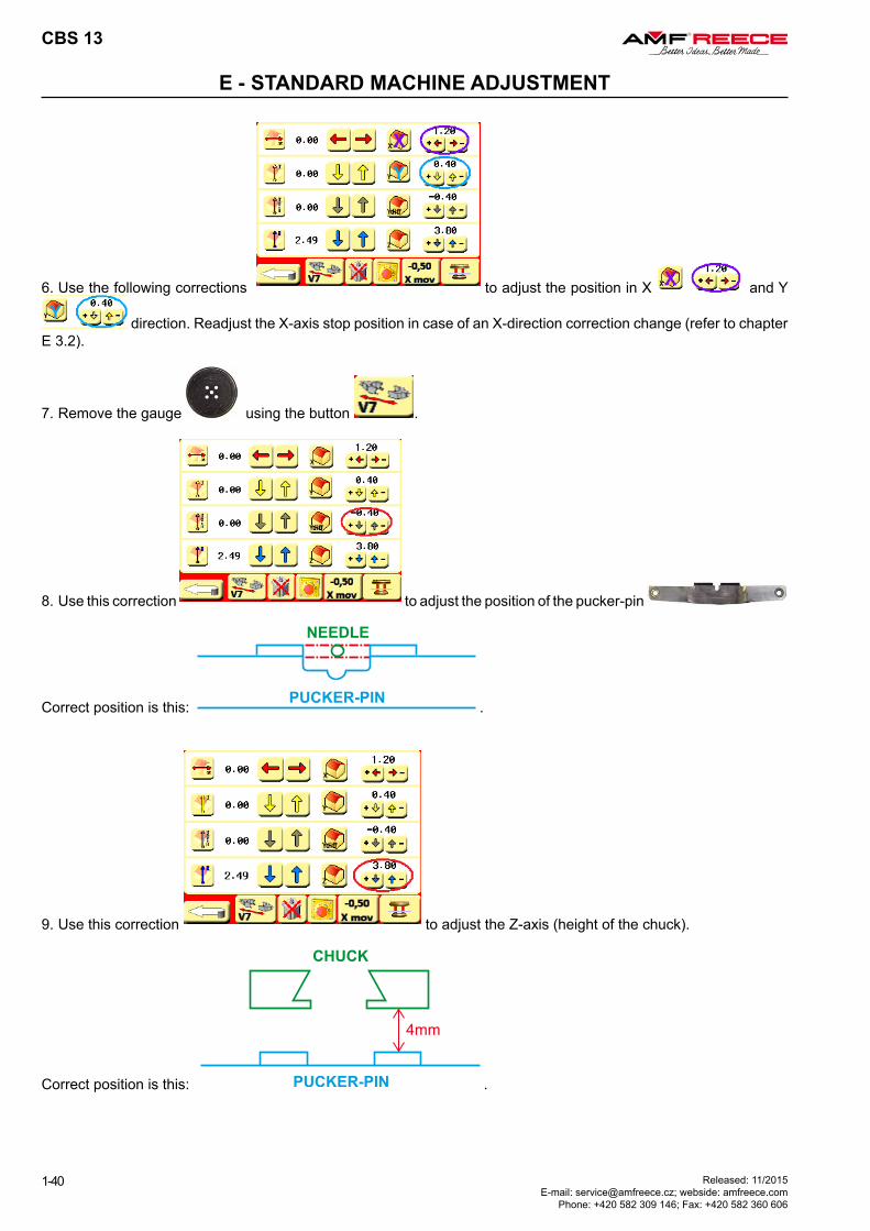
E - STANDARD MACHINE ADJUSTMENT
6. Use the following corrections to adjust the position in X and Y
direction. Readjust the X-axis stop position in case of an X-direction correction change (refer to chapter E 3.2).
7. Remove the gauge using the button .
8. Use this correction to adjust the position of the pucker-pin
Correct position is this: .
9. Use this correction to adjust the Z-axis (height of the chuck).
Correct position is this: .
12 mm
CBS 13
1-41Released: 11/2015 E-mail: [email protected]; webside: amfreece.com Phone: +420 582 309 146; Fax: +420 582 360 606
E - STANDARD MACHINE ADJUSTMENT
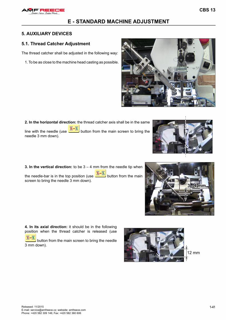
5. AUXILIARY DEVICES
5.1. Thread Catcher Adjustment
The thread catcher shall be adjusted in the following way:
1. To be as close to the machine head casting as possible.
2. In the horizontal direction: the thread catcher axis shall be in the same
line with the needle (use button from the main screen to bring the needle 3 mm down).
3. In the vertical direction: to be 3 – 4 mm from the needle tip when
the needle-bar is in the top position (use button from the main screen to bring the needle 3 mm down).
4. In its axial direction: it should be in the following position when the thread catcher is released (use
button from the main screen to bring the needle 3 mm down).
1 mm
26,5 mm
(26) mm
42,5 mm
CBS 13
1-42 Released: 11/2015 E-mail: [email protected]; webside: amfreece.com
Phone: +420 582 309 146; Fax: +420 582 360 606
E - STANDARD MACHINE ADJUSTMENT
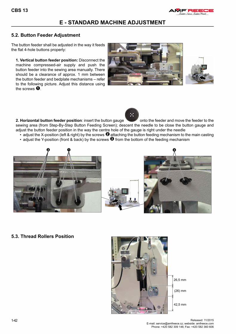
5.2. Button Feeder Adjustment
The button feeder shall be adjusted in the way it feeds the flat 4-hole buttons properly:
1. Vertical button feeder position: Disconnect the machine compressed-air supply and push the button feeder into the sewing area manually. There should be a clearance of approx. 1 mm between the button feeder and bedplate mechanisms – refer to the following picture. Adjust this distance using the screws 1 .
2. Horizontal button feeder position: insert the button gauge onto the feeder and move the feeder to the sewing area (from Step-By-Step Button Feeding Screen); descent the needle to be close the button gauge and adjust the button feeder position in the way the centre hole of the gauge is right under the needle
• adjust the X-position (left & right) by the screws 2 attaching the button feeding mechanism to the main casting• adjust the Y-position (front & back) by the screws 3 from the bottom of the feeding mechanism
5.3. Thread Rollers Position
THROAT-PLATE
FIXED KNIFE
FIXED KNIFE
MOVEABLE KNIFE
1 mm
CBS 13
1-43Released: 11/2015 E-mail: [email protected]; webside: amfreece.com Phone: +420 582 309 146; Fax: +420 582 360 606
E - STANDARD MACHINE ADJUSTMENT
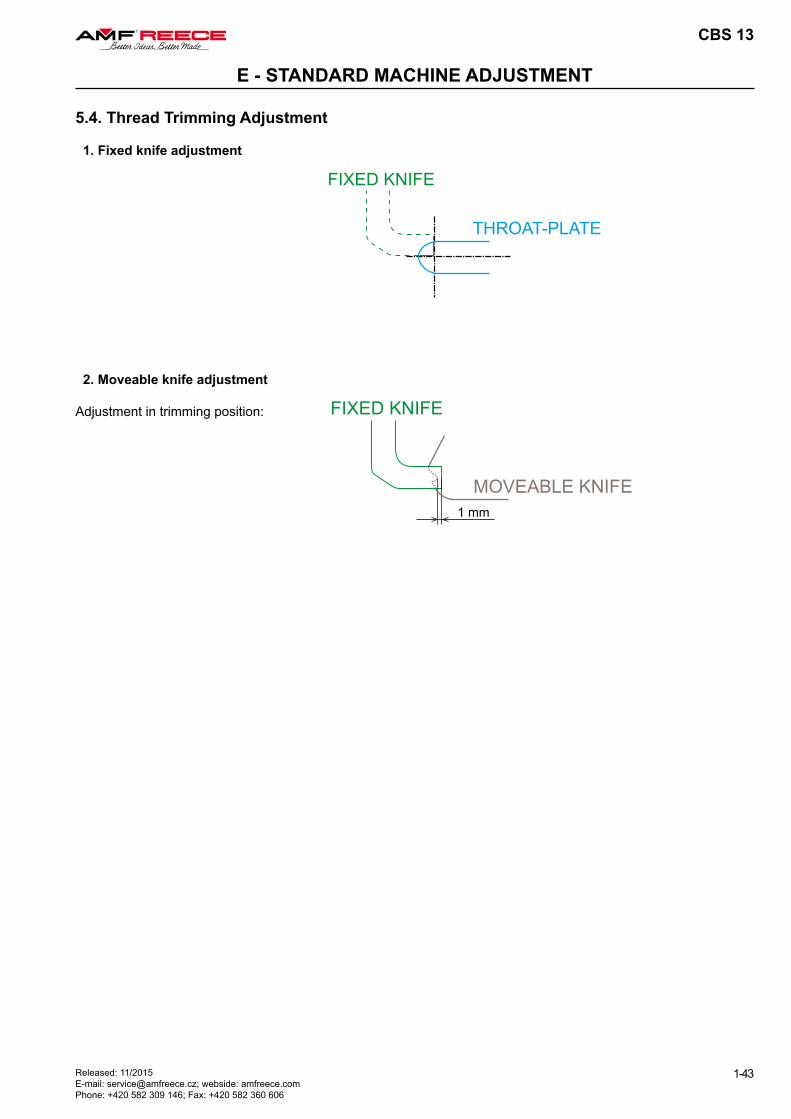
5.4. Thread Trimming Adjustment
1. Fixed knife adjustment
2. Moveable knife adjustment
Adjustment in trimming position:
CBS 13
1-44
F - MACHINE MAINTENANCE
Released: 11/2015 E-mail: [email protected]; webside: amfreece.com
Phone: +420 582 309 146; Fax: +420 582 360 606
WARNING! • Check the condition of electric cables regularly! Make sure they are not damaged!• Check that there are no damages on the safety covers. Change damaged covers for good ones or order them!• Do not put fingers into the area of sewing needle or cutting mechanism under any circumstances! • Do not modify the machine in any way that could limit safety components!
CAUTION! • Do not miss out doing regular maintenance.• If there is power system breakdown, switch off the main power switch.• Do not remove, modify or remove safety labels.• Do not work on the machine intoxicated or impaired. • Make sure that lighting equipment for the working area does not exceed 750 Lux.
1. Machine Cleaning and Maintenance
CAUTION!Before you start the maintenance or cleaning, switch off the power supply and disconnect the air supply from the machine!
1.1. Daily Cleaning and Checking
To ensure machine long life and reliability, it is important to apply below mentioned steps on daily bases after work shift.
1.1.1. Sewing mechanism cleaning
Clean all moveable mechanism (linear guides, teeth-wheels and racks, bushings, etc.) using compressed air.
±45°
CBS 13
1-45Released: 11/2015 E-mail: [email protected]; webside: amfreece.com Phone: +420 582 309 146; Fax: +420 582 360 606
F - MACHINE MAINTENANCE
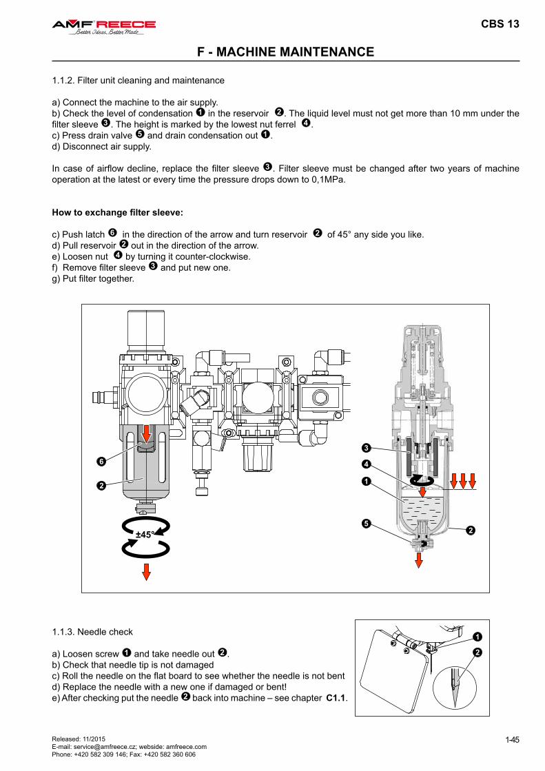
1.1.2. Filter unit cleaning and maintenance
a) Connect the machine to the air supply. b) Check the level of condensation 1 in the reservoir 2 . The liquid level must not get more than 10 mm under the filter sleeve 3 . The height is marked by the lowest nut ferrel 4 . c) Press drain valve 5 and drain condensation out 1 .d) Disconnect air supply.
In case of airflow decline, replace the filter sleeve 3 . Filter sleeve must be changed after two years of machine operation at the latest or every time the pressure drops down to 0,1MPa.
How to exchange filter sleeve:
c) Push latch 6 in the direction of the arrow and turn reservoir 2 of 45° any side you like.d) Pull reservoir 2 out in the direction of the arrow.e) Loosen nut 4 by turning it counter-clockwise.f) Remove filter sleeve 3 and put new one.g) Put filter together.
1.1.3. Needle check
a) Loosen screw 1 and take needle out 2 . b) Check that needle tip is not damaged c) Roll the needle on the flat board to see whether the needle is not bentd) Replace the needle with a new one if damaged or bent!e) After checking put the needle 2 back into machine – see chapter C1.1.
1 PHASE
200-240V
50/60 Hz
CBS 13
1-46
F - MACHINE MAINTENANCE
Released: 11/2015 E-mail: [email protected]; webside: amfreece.com
Phone: +420 582 309 146; Fax: +420 582 360 606
1.2. Cleaning And Checking As Needed
Apply instructions bellow as needed with regard to machine production workload.
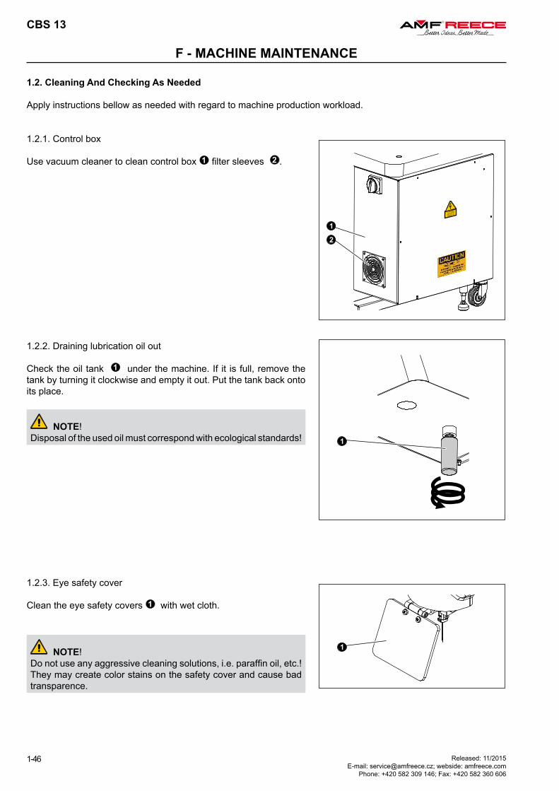
1.2.1. Control box
Use vacuum cleaner to clean control box 1 filter sleeves 2 .
1.2.2. Draining lubrication oil out
Check the oil tank 1 under the machine. If it is full, remove the tank by turning it clockwise and empty it out. Put the tank back onto its place.
NOTE!Disposal of the used oil must correspond with ecological standards!
1.2.3. Eye safety cover
Clean the eye safety covers 1 with wet cloth.
NOTE!Do not use any aggressive cleaning solutions, i.e. paraffin oil, etc.! They may create color stains on the safety cover and cause bad transparence.
CBS 13
1-47Released: 11/2015 E-mail: [email protected]; webside: amfreece.com Phone: +420 582 309 146; Fax: +420 582 360 606
F - MACHINE MAINTENANCE
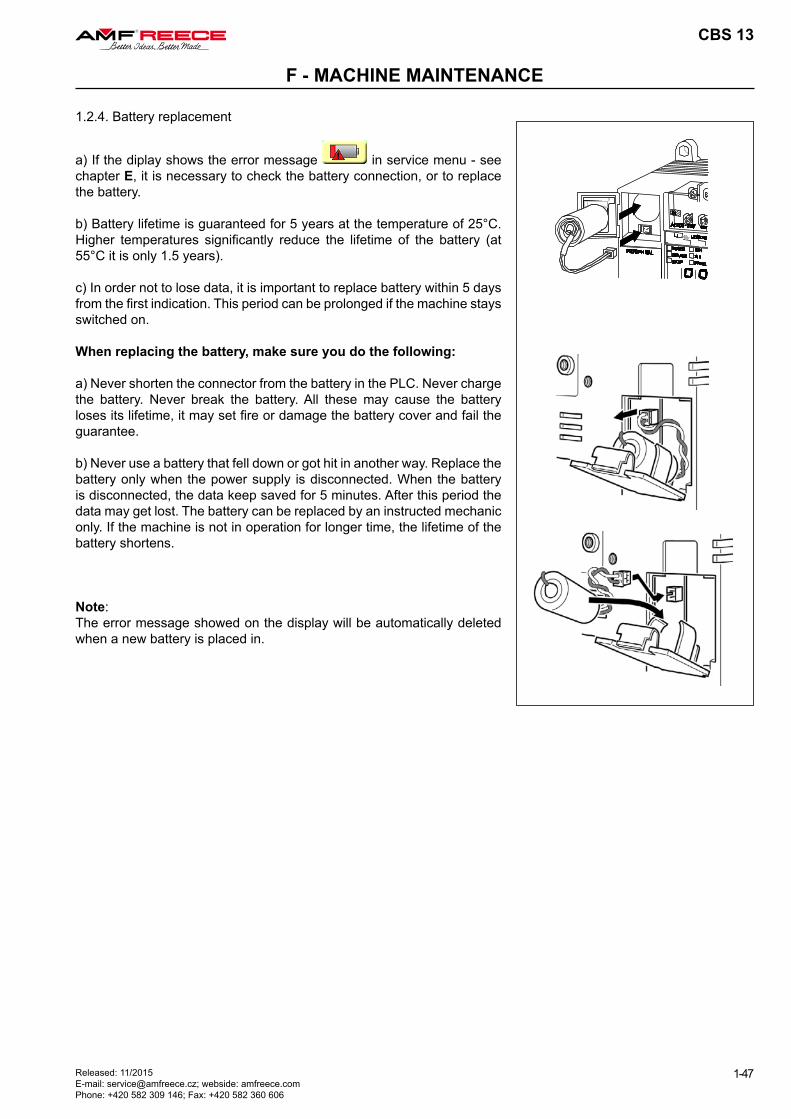
1.2.4. Battery replacement
a) If the diplay shows the error message in service menu - see chapter E, it is necessary to check the battery connection, or to replace the battery.
b) Battery lifetime is guaranteed for 5 years at the temperature of 25°C. Higher temperatures significantly reduce the lifetime of the battery (at 55°C it is only 1.5 years).
c) In order not to lose data, it is important to replace battery within 5 days from the first indication. This period can be prolonged if the machine stays switched on.
When replacing the battery, make sure you do the following:
a) Never shorten the connector from the battery in the PLC. Never charge the battery. Never break the battery. All these may cause the battery loses its lifetime, it may set fire or damage the battery cover and fail the guarantee.
b) Never use a battery that fell down or got hit in another way. Replace the battery only when the power supply is disconnected. When the battery is disconnected, the data keep saved for 5 minutes. After this period the data may get lost. The battery can be replaced by an instructed mechanic only. If the machine is not in operation for longer time, the lifetime of the battery shortens.
Note:The error message showed on the display will be automatically deleted when a new battery is placed in.
CBS 13
1-48
F - MACHINE MAINTENANCE
Released: 11/2015 E-mail: [email protected]; webside: amfreece.com
Phone: +420 582 309 146; Fax: +420 582 360 606
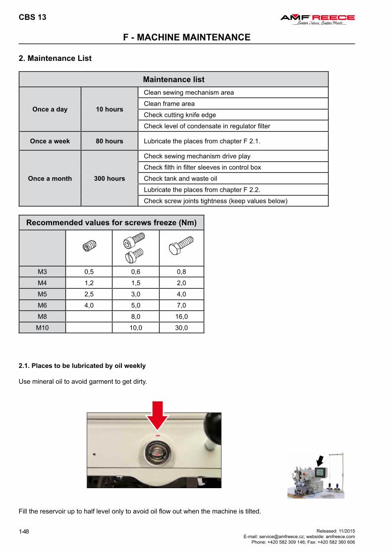
2. Maintenance List
Maintenance list
Once a day 10 hours
Clean sewing mechanism areaClean frame areaCheck cutting knife edgeCheck level of condensate in regulator filter
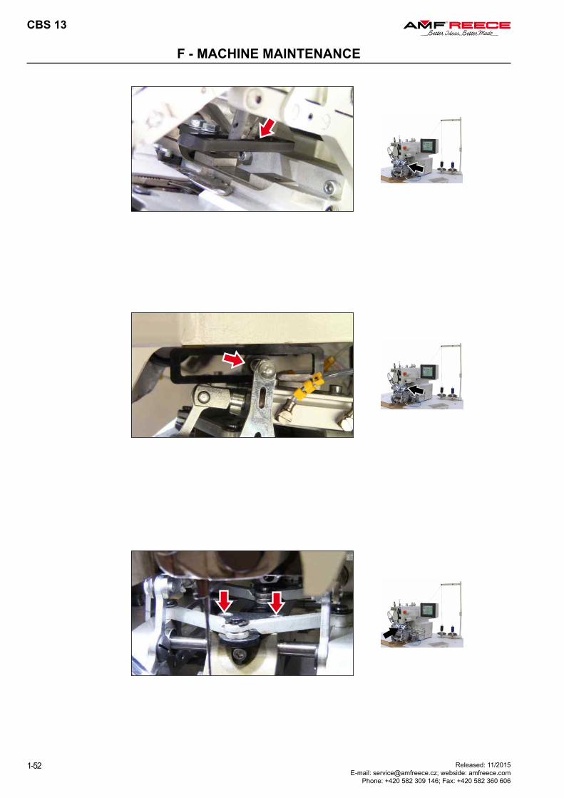
Once a week 80 hours Lubricate the places from chapter F 2.1.
Once a month 300 hours
Check sewing mechanism drive playCheck filth in filter sleeves in control boxCheck tank and waste oilLubricate the places from chapter F 2.2.Check screw joints tightness (keep values below)
Recommended values for screws freeze (Nm)
M3 0,5 0,6 0,8M4 1,2 1,5 2,0M5 2,5 3,0 4,0M6 4,0 5,0 7,0M8 8,0 16,0
M10 10,0 30,0
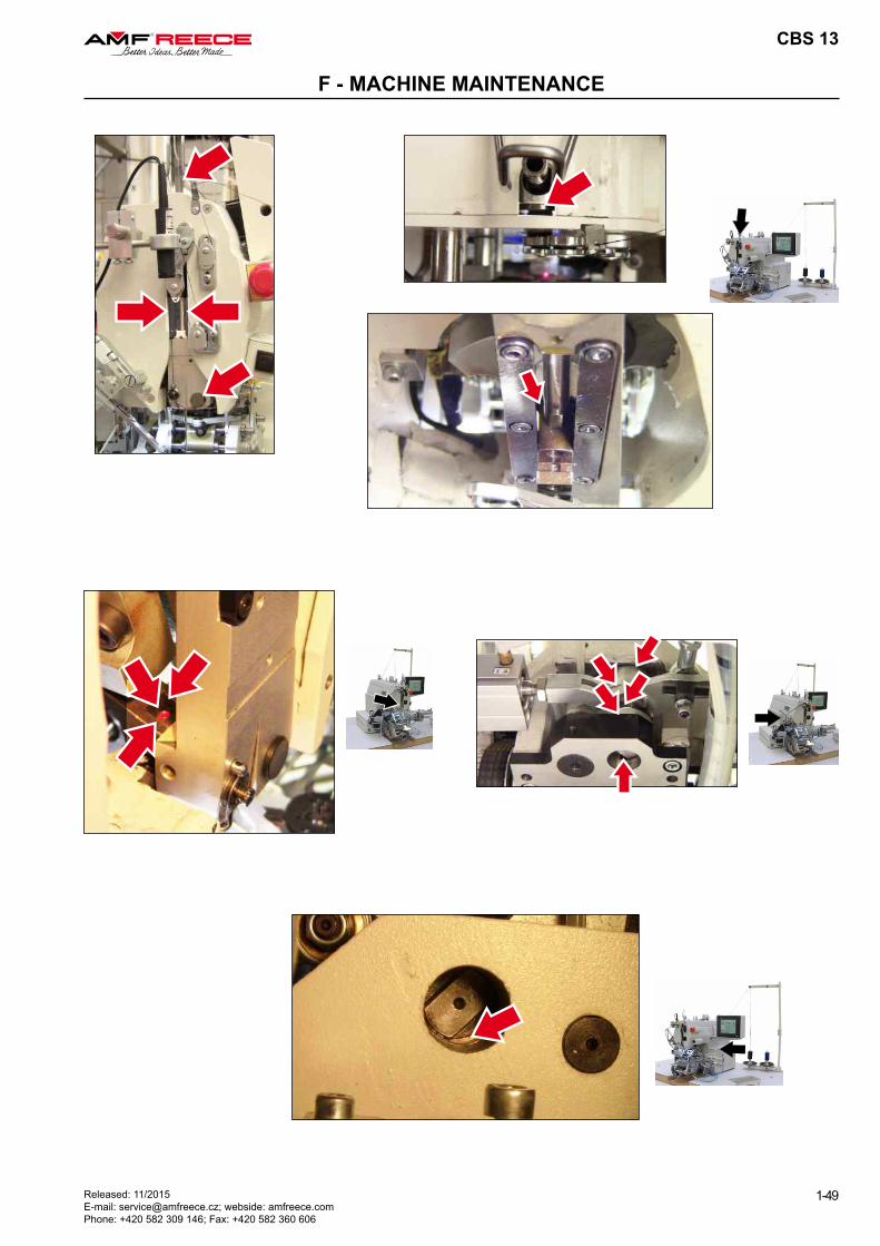
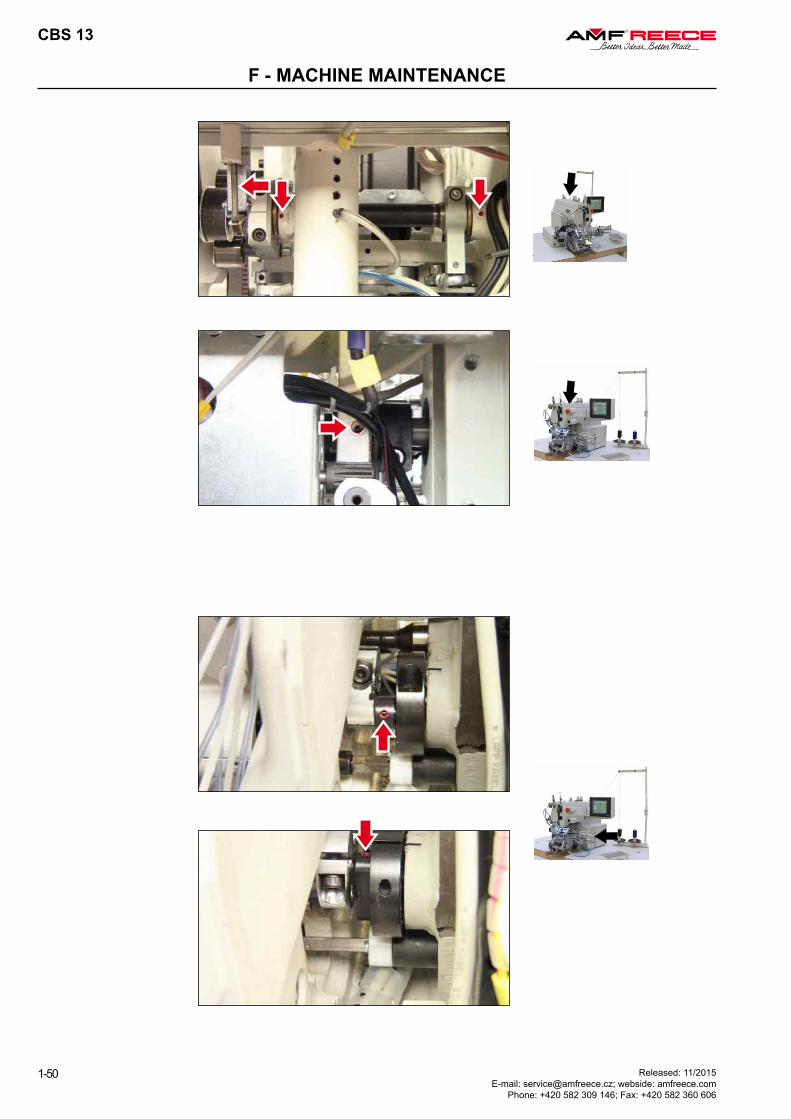
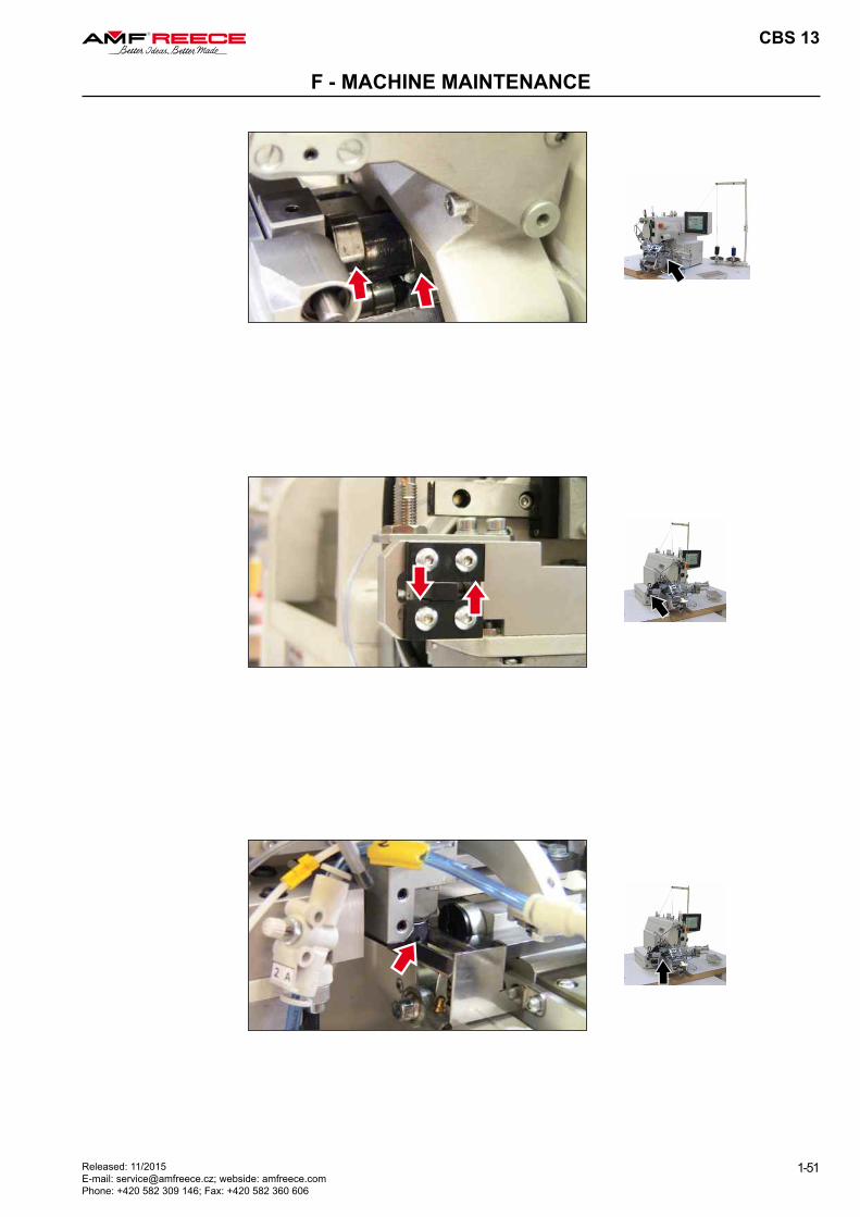
2.1. Places to be lubricated by oil weekly
Use mineral oil to avoid garment to get dirty.
Fill the reservoir up to half level only to avoid oil flow out when the machine is tilted.
CBS 13
1-49Released: 11/2015 E-mail: [email protected]; webside: amfreece.com Phone: +420 582 309 146; Fax: +420 582 360 606
F - MACHINE MAINTENANCE
CBS 13
1-50
F - MACHINE MAINTENANCE
Released: 11/2015 E-mail: [email protected]; webside: amfreece.com
Phone: +420 582 309 146; Fax: +420 582 360 606
CBS 13
1-51Released: 11/2015 E-mail: [email protected]; webside: amfreece.com Phone: +420 582 309 146; Fax: +420 582 360 606
F - MACHINE MAINTENANCE
CBS 13
1-52
F - MACHINE MAINTENANCE
Released: 11/2015 E-mail: [email protected]; webside: amfreece.com
Phone: +420 582 309 146; Fax: +420 582 360 606
CBS 13
1-53Released: 11/2015 E-mail: [email protected]; webside: amfreece.com Phone: +420 582 309 146; Fax: +420 582 360 606
F - MACHINE MAINTENANCE
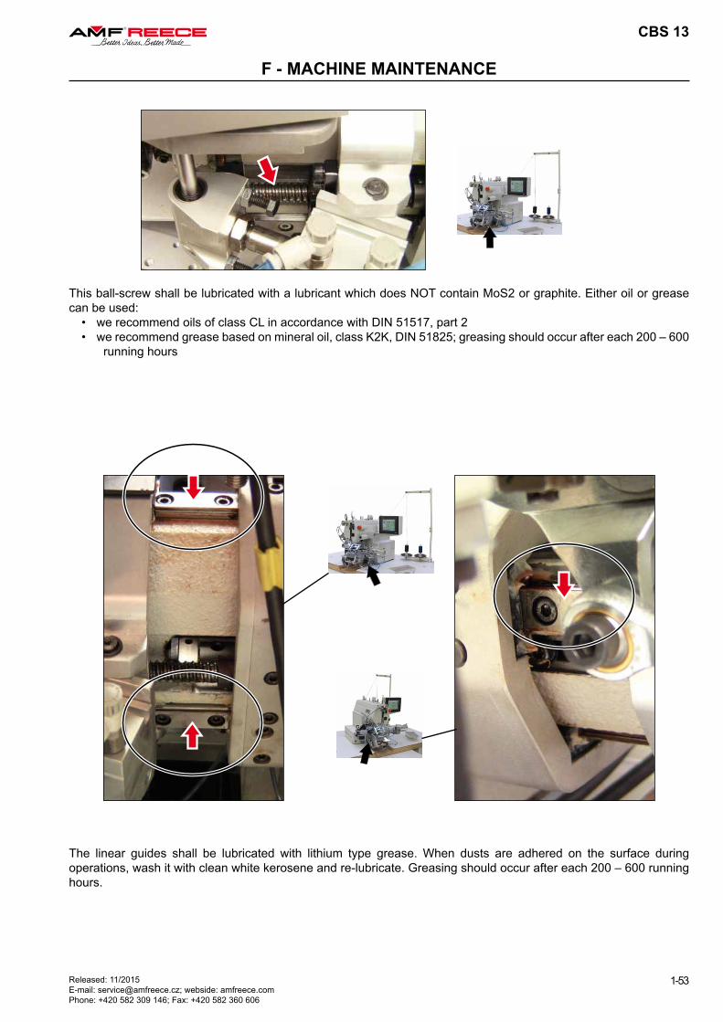
This ball-screw shall be lubricated with a lubricant which does NOT contain MoS2 or graphite. Either oil or grease can be used:
• we recommend oils of class CL in accordance with DIN 51517, part 2• we recommend grease based on mineral oil, class K2K, DIN 51825; greasing should occur after each 200 – 600
running hours
The linear guides shall be lubricated with lithium type grease. When dusts are adhered on the surface during operations, wash it with clean white kerosene and re-lubricate. Greasing should occur after each 200 – 600 running hours.
CBS 13
1-54
F - MACHINE MAINTENANCE
Released: 11/2015 E-mail: [email protected]; webside: amfreece.com
Phone: +420 582 309 146; Fax: +420 582 360 606
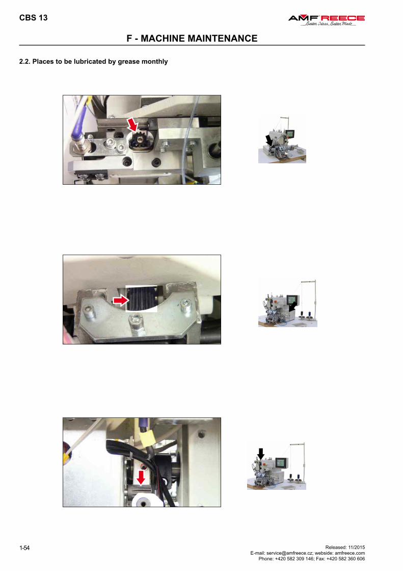
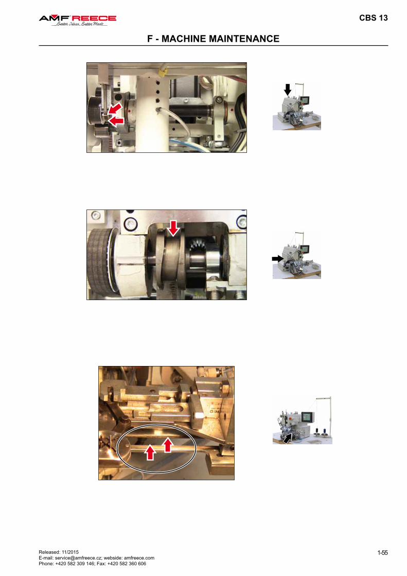
2.2. Places to be lubricated by grease monthly
CBS 13
1-55Released: 11/2015 E-mail: [email protected]; webside: amfreece.com Phone: +420 582 309 146; Fax: +420 582 360 606
F - MACHINE MAINTENANCE
CBS 13
1-56
F - MACHINE MAINTENANCE
Released: 11/2015 E-mail: [email protected]; webside: amfreece.com
Phone: +420 582 309 146; Fax: +420 582 360 606
3. Machine Disposal
3.1. To make sure the machine is disposed ecologically, it is necessary to remove all nonsteel parts from machine. Once such parts are removed, partial disassembly is needed, covers be removed, machine arm dismantled and machine pulled out from the frame.
3.2. Separate aluminum parts, hard aluminum parts, non-ferrous metal parts and plastic parts and have them processed separately.
CBS 13
1-57Released: 11/2015 E-mail: [email protected]; webside: amfreece.com Phone: +420 582 309 146; Fax: +420 582 360 606
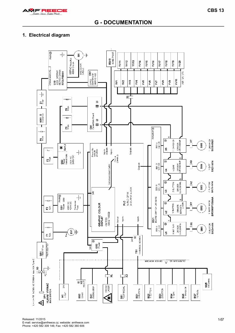
G - DOCUMENTATION
1. Electrical diagram

CBS 13
2-1Revised: 11/2015E-mail: [email protected]; webside: www.amfreece.comPhone: +420 582 309 146; Fax: +420 582 360 606
TROUBLESHOOTING
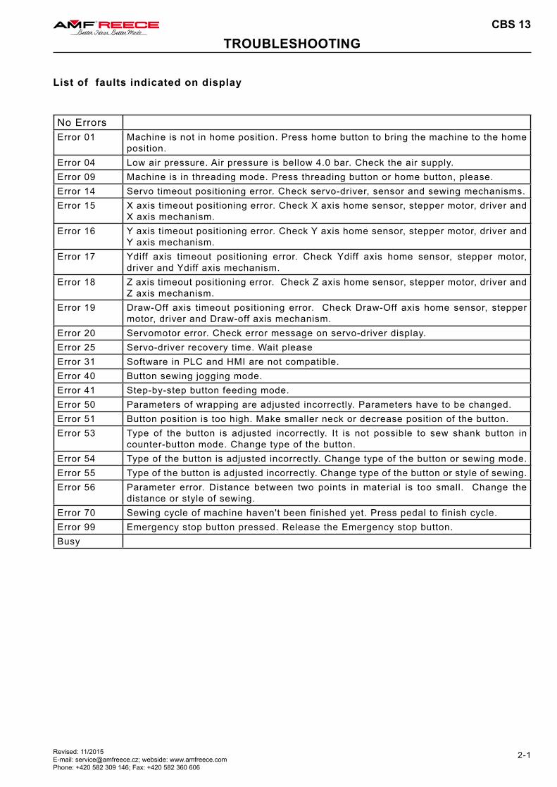
List of faults indicated on display
No ErrorsError 01 Machine is not in home position. Press home button to bring the machine to the home
position.Error 04 Low air pressure. Air pressure is bellow 4.0 bar. Check the air supply.Error 09 Machine is in threading mode. Press threading button or home button, please.Error 14 Servo timeout positioning error. Check servo-driver, sensor and sewing mechanisms.Error 15 X axis timeout positioning error. Check X axis home sensor, stepper motor, driver and
X axis mechanism.Error 16 Y axis timeout positioning error. Check Y axis home sensor, stepper motor, driver and
Y axis mechanism.Error 17 Ydiff axis timeout positioning error. Check Ydiff axis home sensor, stepper motor,
driver and Ydiff axis mechanism.Error 18 Z axis timeout positioning error. Check Z axis home sensor, stepper motor, driver and
Z axis mechanism.Error 19 Draw-Off axis timeout positioning error. Check Draw-Off axis home sensor, stepper
motor, driver and Draw-off axis mechanism.Error 20 Servomotor error. Check error message on servo-driver display.Error 25 Servo-driver recovery time. Wait please Error 31 Software in PLC and HMI are not compatible.Error 40 Button sewing jogging mode. Error 41 Step-by-step button feeding mode.Error 50 Parameters of wrapping are adjusted incorrectly. Parameters have to be changed.Error 51 Button position is too high. Make smaller neck or decrease position of the button.Error 53 Type of the button is adjusted incorrectly. It is not possible to sew shank button in
counter-button mode. Change type of the button.Error 54 Type of the button is adjusted incorrectly. Change type of the button or sewing mode.Error 55 Type of the button is adjusted incorrectly. Change type of the button or style of sewing.Error 56 Parameter error. Distance between two points in material is too small. Change the
distance or style of sewing.Error 70 Sewing cycle of machine haven't been finished yet. Press pedal to finish cycle.Error 99 Emergency stop button pressed. Release the Emergency stop button. Busy