Embed Size (px)
Citation preview
PART III – TECHNICAL SPECIFICATIONS
(Section 1)
Locomotive(s)
RFP FQ11291/FRV
SPN-0019 LOCOMOTIVE Rev. 2 - 4/8/2011 Page 2 of 77
Table of Contents
1.0 SCOPE........................................................................................................................................................ 4
1.1 GENERAL REQUIREMENTS .......................................................................................................................................... 4
1.2 REQUIREMENTS AND ORGANIZATION OF THE TECHNICAL SPECIFICATION ............................................................................. 5
1.3 USE OF TECHNICAL SPECIFICATION ............................................................................................................................... 5
1.4 SYSTEM DESIGN RESPONSIBILITY ................................................................................................................................... 5
2.0 APPLICABLE DOCUMENTS ......................................................................................................................... 6
3.0 TECHNICAL SPECIFICATIONS ...................................................................................................................... 7
3.1 GENERAL ................................................................................................................................................................. 7
3.2 OPERATING ENVIRONMENTS ....................................................................................................................................... 7
3.3 TRACKWORK PARAMETERS ......................................................................................................................................... 8
3.4 GENERAL DESIGN REQUIREMENTS ................................................................................................................................. 8
3.5 DIMENSIONS .......................................................................................................................................................... 10
3.6 NOISE EXPOSURE: ................................................................................................................................................... 10
3.7 CARBODY .............................................................................................................................................................. 11
3.8 TRUCKS ................................................................................................................................................................. 15
3.9 PROPULSION - GENERAL ........................................................................................................................................... 20
3.10 DIESEL ENGINE SYSTEM .......................................................................................................................................... 21
3.11 PRIMARY POWER DISTRIBUTION ............................................................................................................................... 22
3.12 TRACTION MOTORS ............................................................................................................................................... 22
3.13 GEAR UNIT ........................................................................................................................................................... 23
3.14 COUPLING ........................................................................................................................................................... 24
3.15 FUEL TANK ........................................................................................................................................................... 24
3.16 AUTOMATIC FIRE SENSING AND SUPPRESSION SYSTEM (AFSS) ....................................................................................... 25
3.17 BRAKE SYSTEM ..................................................................................................................................................... 26
3.18 CUTOUT COCKS..................................................................................................................................................... 28
3.19 ELECTRICAL SYSTEM ............................................................................................................................................... 28
3.20 MATERIALS .......................................................................................................................................................... 40
3.21 PAINTING ............................................................................................................................................................ 46
3.22 CLEARANCE REQUIREMENTS .................................................................................................................................... 48
3.23 COUPLER ............................................................................................................................................................. 49
3.24 OPERATOR’S CAB .................................................................................................................................................. 49
3.25 LIGHTING ............................................................................................................................................................ 54
3.26 HEATING, VENTILATION, AND AIR CONDITIONING ......................................................................................................... 56
3.27 PNEUMATIC SYSTEM REQUIREMENTS ........................................................................................................................ 57
3.28 HYDRAULIC SYSTEM REQUIREMENTS (IF PROVIDED) ...................................................................................................... 59
3.29 RADIO ................................................................................................................................................................ 60
3.30 MANUALS AND DOCUMENTATION ........................................................................................................................... 60
3.31 MAINTENANCE SPARES .......................................................................................................................................... 62
4.0 INSPECTION AND ACCEPTANCE TESTING ................................................................................................. 63
SPN-0019 LOCOMOTIVE Rev. 2 - 4/8/2011 Page 3 of 77
4.1 INITIAL INSPECTION ................................................................................................................................................. 63
4.2 ACCEPTANCE TESTING .............................................................................................................................................. 64
5.0 SAFETY CERTIFICATION............................................................................................................................ 64
5.1 REQUIREMENTS: .................................................................................................................................................... 64
6.0 WARRANTY AND RELIABILITY .................................................................................................................. 65
6.1 WARRANTY ........................................................................................................................................................... 65
6.2 RELIABILITY ........................................................................................................................................................... 65
7.0 TRAINING ................................................................................................................................................ 69
7.1 REQUIREMENTS/DELIVERABLES ................................................................................................................................. 69
8.0 DELIVERY SCHEDULE................................................................................................................................ 73
8.1 SHIPPING .............................................................................................................................................................. 73
9.0 APPENDICES ............................................................................................................................................ 74
9.1 STANDARD CLEARANCE PACKAGE .............................................................................................................................. 74
9.1.1 Design Loading and Measurements ........................................................................................................... 74
9.1.2 Design Vehicle Dynamic Outline Diagram – Tangent Track ....................................................................... 75
9.1.3 WMATA Rapid Transit Car Clearance Envelope ......................................................................................... 76
9.1.4 METRO Rapid Transit Car – Dynamic Outline, Under Floor Car Clearance ................................................ 77
SPN-0019 LOCOMOTIVE Rev. 2 - 4/8/2011 Page 4 of 77
1.0 Scope
1.1 GENERAL REQUIREMENTS
1.1.1 This package includes specifications for the manufacture and delivery of a 60 Ton
Heavy Rail Diesel-Electric Locomotive(s) (hereafter referred to as the
“Locomotive”), that is capable either individually or as part of a multiple unit
(M.U.), of pulling a nine (9) car rail train weighing a total of 1,000,000 lbs [not
including the Locomotive(s)], up a 4% grade from standstill. The offeror shall
clearly state in its proposal and shall price individually the number of
Locomotive(s) required to meet this requirement. In addition, the Locomotive
shall not weigh more than 120,000 lbs. each (unless it conforms to the structural
requirements of Appendix 9.1) and shall be capable of traveling at speeds up to
35 mph.
1.1.2 .The Contractor shall provide spare parts in accordance with Section 3.31 and
Section 6.1.4.
1.1.3 The Contractor shall train WMATA’s staff and provide training programs in the
operation and maintenance of the Locomotive(s). All training provided by the
Contractor shall be fully documented with copies provided to WMATA.
1.1.4 As part of the bid proposal, the Contractor shall supply a list of recommended
specialized and general tools, and test equipment for diagnosis, maintenance and
repair of the Locomotive(s). The supply of specialized and general tools, and test
equipment shall then be as agreed between WMATA and the Contractor prior to
Contract Award.
1.1.5 The Locomotive(s) shall be put into service by a factory trained representative(s).
The Contractor shall have after sales service support with available factory
trained service technicians to assist in start-up and training.
1.1.6 The Locomotive(s) shall be free from defects such as incomplete welds, welds
that cross welds, corrosion, loose or improper fasteners, any leaks or
contamination, and any other defects that would impair or limit the operation or
serviceability. All welds must comply with the associated and established
American Welding Society (AWS) standards.
1.1.7 The Locomotive(s) shall comply and conform to all Federal, State, and Local
environmental, safety, and health regulations in force, at the time of delivery.
SPN-0019 LOCOMOTIVE Rev. 2 - 4/8/2011 Page 5 of 77
1.1.8 The Contractor shall supply one layout-drawing (to scale) showing the
Locomotive(s) dimensions and component placement on the completed vehicle.
The layout-drawing shall be submitted as part of the submission package.
1.2 REQUIREMENTS AND ORGANIZATION OF THE TECHNICAL
SPECIFICATION
1.2.1 This Technical Specification (TS) defines the technical requirements set forth by
WMATA’s Maintenance of Way department for the procurement of the
Locomotive(s).
1.2.2 The technical requirements in this Specification document are expressed
primarily in terms of performance and function, with technical features specified
only when necessary.
1.2.3 If the Contractor can offer service proven designs and systems which meet other
appropriate specifications or standards that differ from those specified herein,
the Contractor shall present a thorough comparison of those specifications or
standards for review and approval by WMATA. Such approval will not be
unreasonably withheld.
1.3 USE OF TECHNICAL SPECIFICATION
1.3.1 This Specification details the requirements for the design and supply of the
Locomotive(s) to be used on the WMATA System and right of way by WMATA’s
Maintenance of Way department.
1.3.2 This Technical Specification shall be read in conjunction with all other sections of
the contract. In the event of any inconsistencies or conflicts, see General
Provision #27 ‘Order of Precedence.’
1.4 SYSTEM DESIGN RESPONSIBILITY
1.4.1 The Contractor shall assume complete and overall responsibility and adopt best
practices for design, implementation of design and satisfactory operation for
both the subsystems and the complete Locomotive(s).
1.4.2 The Contractor’s responsibility shall include, but shall not be limited to, ensuring
throughout the design, manufacture, and installation stages and commissioning
and warranty periods that components and subsystems are coordinated,
compatible and perform safely and correctly, both together and individually in
accordance with the Specification.
SPN-0019 LOCOMOTIVE Rev. 2 - 4/8/2011 Page 6 of 77
1.4.3 If the functional or technical requirements specified in this document cannot be
met, the Contractor shall identify this and may propose alternatives which are
equivalent or better, for WMATA’s consideration.
2.0 Applicable Documents
a) 49 CFR 238.103, 238.223, 229.121, 231, 223, 229.125, 229.127
b) AAR Standards and Recommended Practices
c) AAR Standard S-580, M-116, M-101, S-538, M-618, M-927
d) AWS D1.1, D1.2, D1.3, C1.1
e) ASTM E138, B32, B33, B187, A36, A606, A588, A488, E94, E142, E390, E446
f) ASME A-53
g) IEEE Standard 11
h) AGMA 140.01, Gear Material Manual
i) APTA SS-M-006, Parking Brake for Locomotives
j) NFPA 130
k) ANSI 80.1, B1.1, B.16.3
l) UL 6 Standard
m) American Pipe Threads B-2.1
n) Section VIII of the ASME Boiler and Pressure Vessel Code
2.1.2 Where national or international standards are quoted in this Technical
Specification, they shall be considered as the minimum requirement. The
Contractor may propose to work to equivalent or more stringent internationally
or nationally recognized standards, subject to approval by WMATA. Submissions
for approval are to be supported by a copy of the proposed standards, a detailed
comparison of the quoted and proposed standards and, where applicable, an
English translation of the proposed standard.
2.1.3 The version of the standard shall be the edition/revision which is in force at the
date of bid submittal.
SPN-0019 LOCOMOTIVE Rev. 2 - 4/8/2011 Page 7 of 77
2.1.4 Where quoted standards duplicate or conflict with the requirements of this
Specification for a particular criterion, the more stringent requirement shall be
assumed to apply. Any conflict in requirements shall be brought to the attention
of WMATA for approval.
3.0 Technical Specifications
3.1 GENERAL
3.1.1 The Locomotive(s) is intended for maintenance operation on the WMATA System
that operates in the following regions: Washington DC, Virginia, and Maryland.
Track exists both underground and above ground. It is expected that the
Locomotive(s) shall be able to operate in both track locations within the three
regions which WMATA provides service as specified above.
3.2 OPERATING ENVIRONMENTS
3.2.1 The Locomotive(s) shall be able to operate on the WMATA System, and comply
with all the clearance requirements of Appendix 9.1.
3.2.2 The Locomotive(s) shall operate in the presence of airborne pollutants, such as
dust, acids, and oxides, characteristic of the operating environment in the
Washington DC Metropolitan Area. The Contractor shall consider the
environmental conditions in the design of all aspects of the Locomotive.
3.2.3 The Locomotive shall be capable of being operated at the specified performance
levels and stored without equipment degradation under the following
environmental conditions:
a) Ambient Temperature: -5° F to 105° F
b) Relative Humidity: 20% to 100%, including conditions of condensation
c) Maximum Rainfall: 12” in 24 hours
d) Maximum Snowfall: 23” in 24 hours
e) Wind Speed: 80 mph (operational), 120 mph (storage)
f) Glaze or Freezing Rain: Two or three times per year
3.2.4 The temperatures shown only represent ambient temperature conditions.
SPN-0019 LOCOMOTIVE Rev. 2 - 4/8/2011 Page 8 of 77
3.2.5 The effect of increased temperatures due to solar radiation on the carbody and
heat produced during operation of equipment under the environmental
extremes specified above must not result in degradation of equipment
performance or equipment reliability.
3.3 TRACKWORK PARAMETERS
3.3.1 The trackwork of the WMATA System are based on the following dimensional
criteria:
a) Minimum radius of track curve: 225’
b) Maximum grade: 6%
c) Turnouts: AREMA Nos. 6 - 20
d) Maximum super elevation: 6”
e) Passenger cars coupler height: (Nominal) 22-1/2”
f) Locomotive coupler height: AAR 34-1/2”
3.4 GENERAL DESIGN REQUIREMENTS
3.4.1 The Locomotive(s) shall be capable of pulling a nine (9) car rail train weighing
1,000,000 lbs [not including the Locomotive(s)], up a 4% grade from standstill.
The offeror shall clearly state in its proposal the number of locomotives (either
individually or in M.U.) that are required to meet this requirement. The
Locomotive(s) shall provide the maximum tractive effort at the rail practical for
its size, adhesion consideration, all specification parameters, and WMATA
operations requirements. The Contractor shall supply a net tractive effort vs.
speed curve for the proposed Locomotive(s) with its proposal. The Contractor
shall provide with their proposal an analysis of the pulling capabilities of the
locomotive(s) being proposed. The analysis shall take into account grade and
adhesion constraints. The Locomotive(s) shall utilize the latest anti-slip or anti-
spin technology to prevent wheel spin while meeting the requirements listed
above.
3.4.2 The Locomotive(s) shall incorporate a design that allows ease of access, service,
replacement, and adjustment by maintenance and operational personnel
including filters, fluids, and other components. All major Locomotive
components shall be of a service-proven design.
SPN-0019 LOCOMOTIVE Rev. 2 - 4/8/2011 Page 9 of 77
3.4.3 All system components, including but not limited to, electrical, hydraulic,
pneumatic, HVAC, and engine, shall be sized to meet the requirements within this
specification and to operate on the WMATA System.
3.4.4 Each Locomotive shall weigh no more than 120,000 lbs. (unless it conforms to the
structural requirements of Appendix 9.1)
3.4.5 Travel speeds shall be equal in both directions and shall be capable of traveling at
speeds up to 35 mph.
3.4.6 The Contractor shall ensure that each Locomotive meets all the applicable
regulatory requirements, except where noted otherwise, including but not
limited to, EPA, AAR, and FRA’s latest Regulations and Standards. Structural
strength of the Locomotive(s) is an exception to AAR and FRA requirements.
3.4.7 At a minimum, the prime mover diesel engine shall comply with latest applicable
EPA emission requirements in effect at the date of bid. The prime mover engine
design shall be configured to meet the requirements using ultra-low-sulphur
(ULSF) diesel fuel.
3.4.8 Materials used in the construction of the Locomotive(s) shall comply with the
requirements of 49 CFR Part 238.103 regarding fire safety.
3.4.9 Fuel tanks shall comply with 49 CFR Part 238.223.
3.4.10 It shall be the responsibility of the Contractor to deliver Locomotive(s) that
comply with all applicable laws, rules, and regulations, enacted as of the Closing
Date of this Bid.
3.4.11 All components that have direct contact with the running rail shall be non-
insulated with bonds around any insulated parts to provide shunting of any track
circuitry.
3.4.12 The Locomotive(s) wheel-to-wheel impedance of each wheel axle assembly
shall be less than 0.01 ohm when measured from wheel tread to wheel tread
over the frequency range of 0 to 10 kilohertz.
3.4.13 The Locomotive frame and all components shall be primed and finish painted in
Federal Yellow. To provide a high quality durable finish, the paint and painting
system shall conform to the requirements of Sections 3.21. The paint used on
any part of the Locomotive(s) shall be lead-free.
SPN-0019 LOCOMOTIVE Rev. 2 - 4/8/2011 Page 10 of 77
3.4.14 Exterior decals and signage shall be included for the major systems and
components on the Locomotive(s) in accordance with the CFR. The WMATA logo
shall be included on the cab doors. Locomotive number decals shall be applied to
both sides of the Locomotive in four (4) inch high letters. WMATA will inform the
Contractor as to the numbering and character font style.
3.4.15 The Locomotive shall maintain a minimum of three (3) inches of clearance above
the top of rail at all times.
3.5 DIMENSIONS
3.5.1 Overall length over the coupler faces shall be approximately 66 ft.
3.5.2 Overall height from top of running rail shall not exceed 10’ 10” (reference
clearance drawings in Appendix 9.1).
3.5.3 Width overall shall not exceed 10’ (reference clearance drawing in Appendix 9.1).
3.5.4 Length between truck centers shall not be less than 43’ and conformant to
structural requirements of Appendix 9.1.
3.5.5 End over hangs (truck center to coupler pulling face) shall be 10’0” to 11’6”
independent of length between truck centers.
3.6 NOISE EXPOSURE:
3.6.1 Cab interior noise:
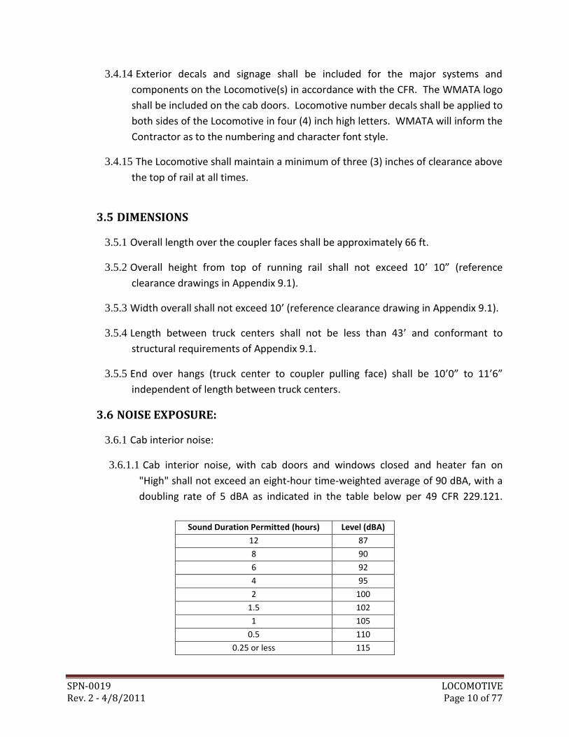
3.6.1.1 Cab interior noise, with cab doors and windows closed and heater fan on
"High" shall not exceed an eight-hour time-weighted average of 90 dBA, with a
doubling rate of 5 dBA as indicated in the table below per 49 CFR 229.121.
Sound Duration Permitted (hours) Level (dBA)
12 87
8 90
6 92
4 95
2 100
1.5 102
1 105
0.5 110
0.25 or less 115
SPN-0019 LOCOMOTIVE Rev. 2 - 4/8/2011 Page 11 of 77
3.6.2 Exterior Noise:
3.6.2.1 Noise shall not exceed permissible exposure for operators, assistants, and
workmen for a continuous eight-hour work day. Noise sources and the
Locomotive cab shall be treated to bring about total compliance of the
following conditions:
a) Less than 90 dBA at 10 feet from the power plant housing; and
b) Less than 85 dBA at 50 feet from the centerline of the track; or
c) Comply with MIL-HDBOOK-1472, Human Engineering Design.
3.7 CARBODY
3.7.1 General:
3.7.1.1 The carbody shall have a full width cab. The carbody shall conform to FRA and
OSHA regulations and AAR Standards and recommended practices (except as
noted in the Specification for structural strength).
3.7.1.2 The Contractor shall confirm watertightness of the cab.
3.7.1.3 Carbody windows, doors, panels, and hatches shall be rattle-free, easy and
safe to operate. Cab doors and windows shall be self-sealing to prevent the
passage of moisture, dust, grit, noise and fumes.
3.7.1.4 All carbody surfaces shall be free from surface defects, sharp edges, corners,
and protrusions; welds on carbody surfaces shall be blended to the extent
possible.
3.7.2 Equipment Access:
3.7.2.1 The carbody shall have warp and buckle-proof hinged equipment doors with
latches to allow access to interior systems and components for inspection and
field servicing, as well as for routine maintenance, repairs, and cleaning.
3.7.2.2 Equipment doors and panels shall be fitted with handles to facilitate opening
and closing. Equipment doors and panels shall be provided with the following:
a) Seals to protect the equipment from dust and contaminants; and
b) A mechanism to securely hold the door in the open position.
SPN-0019 LOCOMOTIVE Rev. 2 - 4/8/2011 Page 12 of 77
3.7.2.3 Roof mounted and accessible equipment shall be capable of replacement by use
of a standard overhead shop crane.
3.7.2.4 The following exterior doors shall be provided:
a) Two cab doors permitting direct access to the operator’s cab from each side of
the Locomotive.
b) Multiple side doors with latches along each hood permitting direct access to
the engine compartment from each side of the Locomotive.
3.7.2.5 Cab doors shall feature a window panel and handhold which conforms to FRA
regulations and AAR requirements.
3.7.2.6 Each door shall be of the maximum possible height, to facilitate personnel
access.
3.7.2.7 Joints and edges shall be thoroughly sealed against moisture, with drain holes
located in the bottom of the doors to allow the escape of condensed moisture.
3.7.2.8 Door hardware shall comply with the following requirements:
a) Hinges shall ensure that each door closes smoothly, without binding or sagging,
b) Each door shall be equipped with a handle operated lock set. Lock sets shall
have handles for operation from both inside and outside the Locomotive. The
handles on the outside of the Locomotive shall be consistent with good
mechanical design, and shall be operable under all weather conditions.
c) Doors shall be locked by means of a hasp and padlock.
d) Doors shall have an external clasp to lock the door utilizing a padlock.
3.7.3 Carbody Ends and Walkways:
3.7.3.1 The end arrangements shall permit safe passage to a coupled car or another
locomotive, while in motion.
3.7.3.2 The ends shall be reinforced to support a bolted-on snowplow.
3.7.3.3 Locomotive fittings shall not interfere with access to items for maintenance or
prevent the removal and replacement of any component.
SPN-0019 LOCOMOTIVE Rev. 2 - 4/8/2011 Page 13 of 77
3.7.4 Handrails, Handholds, Ladders and Steps:
3.7.4.1 Each Locomotive shall include suitable handrails, stanchions, handholds, steps,
and supports to facilitate personnel ingress and egress and to facilitate
equipment access and servicing from both ground level and platforms and
meeting the requirements of 49 CFR 231.
3.7.4.2 Provision shall be provided to give access to the roof for maintenance access.
3.7.4.3 Horizontal handholds shall be provided on each side of the coupler on the
front and rear of the Locomotive, per 49 CFR 231.
3.7.4.4 Handholds and handrails shall be one-piece steel.
3.7.4.5 All steps shall provide for full toe clearance. Recessing of the carbody shall be
provided where necessary. Step treads shall have a skid-resistant surface.
3.7.5 Cab Floor and Walkways:
3.7.5.1 Cab floor, platforms and walkways shall be painted with non-skid type paint, or
equivalent.
3.7.6 Structure:
3.7.6.1 Carbody structure shall be capable of resisting buffing and operating stresses
without binding, permanent deformation or fatigue failure.
3.7.6.2 The carbody structure shall resist a minimum static end load of 200,000 lbs.,
applied on the line of draft, without permanent deformation of the body
structure.
3.7.6.3 The ultimate shear capacity of each collision post (spaced at approximately the
one third point of the width of the platform) at the floor level shall be 300,000
lbs., applied anywhere up to ± 15 degrees from the longitudinal axis of the car.
In addition, each collision post shall have sufficient capacity to withstand a load
of 60,000 lbs. applied 18” above top of floor, up to ± 30 degrees from the
longitudinal axis of the car, with no stress exceeding the yield point.
3.7.6.4 The camber between the truck bolsters shall be positive under all conditions.
3.7.6.5 The carbody structure shall be fully welded. Bolting of structural members shall
not be permitted.
SPN-0019 LOCOMOTIVE Rev. 2 - 4/8/2011 Page 14 of 77
3.7.6.6 The carbody structure shall withstand all required loads, deflections, and
stresses with safety factors consistent with this Specification and industry
standards for locomotives as applicable.
3.7.7 Jacking Pads and Lifting Provisions:
3.7.7.1 Jacking points or equivalent shall be provided. Each point shall be integral with
the carbody side sill at or near the point of attachment of the trucks, and
capable of being used with a vertical jack with no extending leaves, or with an
overhead lifting device. Access to jacking points shall not be obstructed.
3.7.7.2 Two lifting eyes, or functional equivalent, for lifting and/or righting the
Locomotive with cables, shall be provided at each end of the carbody. The
lifting structure at each end shall be capable of supporting at least 1/2 the
weight of a Locomotive with a safety factor of 2, based on yield strength.
3.7.8 Anti-Climber:
3.7.8.1 An anti-climber, conforming to AAR Standard S-580, shall be provided at both
ends of the Locomotive. The anti-climber shall resist a vertical load in either
direction of not less than 100,000 lbf without exceeding the yield point of its
various parts and attachments to the unit structure. The anti-climber shall not
contact any part of a coupled car or locomotive when so coupled.
3.7.9 Coupler Carrier:
3.7.9.1 The coupler carrier, and its connections to the carbody structure, shall be
capable of withstanding a vertical 100,000 lbf downward thrust from the
coupler shank, for any horizontal position of the coupler, without exceeding the
yield points of the materials used.
3.7.10 Equipment Mounting Supports:
3.7.10.1 The carbody structure shall include all necessary mounting support provisions
for electrical and mechanical equipment, including the fuel tank and battery
compartments.
SPN-0019 LOCOMOTIVE Rev. 2 - 4/8/2011 Page 15 of 77
3.7.10.2 Equipment mounting supports shall be designed to withstand loads (overload
and dynamic) consistent with the application. The load factor for the design of
all underfloor, side, end, roof, in-roof and interior equipment, any portion of
the equipment, equipment boxes, equipment hangers, safety hangers, and the
Locomotive supporting structure shall be five and a half in the longitudinal
direction, three in the vertical direction, and two in the lateral direction. The
load shall be equal to the weight of the item multiplied by the appropriate load
factor. The specified tri-axial loadings shall be applied separately; such loading
may develop the ultimate load-carrying capacity of the member being
investigated. Underframe equipment shall not be supported by bolts in
tension.
3.7.10.3 The fuel tank mounting supports shall be capable of withstanding the
maximum combination of static and dynamic loads that can be developed by a
fully loaded and equipped tank system.
3.7.10.4 Truck attachments shall be of sufficient strength to permit lifting the truck
with the carbody. Trucks shall be locked to the carbody. When the Locomotive
is raised off the track, the carbody and the means of locking the truck to the
carbody shall resist a load equal to two times the full weight of the truck
without permanent deformation.
3.7.10.5 Shims may be provided between the carbody and the bolster or truck frame
to compensate for manufacturing tolerances, subject to the following
conditions:
a) Shims shall be steel, and shall be permanently attached,
b) Dimensions and location of each shim shall be identified.
3.8 TRUCKS
3.8.1 General:
3.8.1.1 Each Locomotive shall be equipped with two (2) outboard roller journal
bearing trucks with all axles powered. Trucks shall conform to all applicable AAR
and FRA requirements, specifications, standards and recommended practices,
except as modified by this Specification.
3.8.1.2 Each truck shall have a wheelbase between 6’ 5" and 7’ 6”.
SPN-0019 LOCOMOTIVE Rev. 2 - 4/8/2011 Page 16 of 77
3.8.1.3 Distance between truck centers shall not be less than 43’ and conformant to
structural requirements of Appendix 9.1.
3.8.1.4 Truck assemblies shall be easily removable from the carbody for maintenance,
without the use of any special tools, such as rams, presses or pullers. Carbody
to truck assembly connections shall not contain any press fit joints. Any joints
which could become frozen or locked over time shall be provided with grease
fittings.
3.8.1.5 Truck assemblies shall include all necessary provisions for use of WMATA’s
wheel truing machine to turn wheels. Axle centers shall be accessible without
requiring disassembly of the truck, or its removal from the carbody. Bearing end
caps may be removed for wheel truing.
3.8.1.6 Each truck assembly, including provisions for hand brake rigging mounting,
shall be interchangeable with any other truck assembly.
3.8.1.7 The trucks shall clear all underfloor components when the carbody is raised for
detrucking. Truck mounted and/or carbody mounted parts which must be
removed to allow the removal of the trucks shall be affixed with accessible
bolts, pins, and/or removable fastenings.
3.8.1.8 Truck equalization shall be provided by twin equalizer beams and/or spring
assemblies.
3.8.1.9 Wheels, axles, and roller bearings shall conform to the AAR Manual of
Standards and Recommended Practices.
3.8.1.10 All structural and load-bearing members of the truck assemblies shall be
steel.
3.8.1.11 Provisions shall be made for a minimum of 1-1/2" of vertical adjustment in
1/2" increments of carbody height to compensate for wheel wear.
3.8.1.12 Truck design shall preclude "hunting" or "nosing" at operating speeds.
3.8.1.13 The trucks shall be designed for operation under all possible loading
conditions, with up to 3/4" difference in wheel radii between axle sets, both on
the same truck and between the two trucks. Shimming shall not be utilized to
conform to this requirement.
3.8.1.14 All design criteria shall be evaluated by the Finite Element Analysis (FEA)
method.
SPN-0019 LOCOMOTIVE Rev. 2 - 4/8/2011 Page 17 of 77
3.8.2 Frames:
3.8.2.1 Truck frames shall be of cast and/or welded steel manufacture.
3.8.2.2 Each truck frame shall have accurately located permanent tram marks to
inspect for truck tram. The truck shall be a true rectangle as measured between
the centers of the axle outer ends. Measurements between tram marks shall be
within 1/16" of the centers on each side, and within 1/8" of the diagonally
opposite centers.
3.8.2.3 Each truck frame shall have restraints to hold the wheel and axle assemblies to
the truck frame when it is raised or during a derailment. The restraints must not
be damaged or cause damage to the truck frame or other truck components,
when in use to support the assemblies. Shock absorbers shall not be utilized as
restraints. Pedestal tie bars, if used, shall be machined, fastened and fabricated
in accordance with AAR Manual of Standards and Recommended Practices, M-
116, Grade C.
3.8.2.4 Resilient lateral and vertical stops shall provide a progressive stopping force.
Resilient stops shall develop sufficient force to limit motion properly, but shall
not go solid under any normal operating conditions. Solid mechanical tops shall
prevent excess lateral and vertical displacement.
3.8.2.5 All wearing parts shall be provided with renewable liners of manganese steel,
Teflon or other similar materials. Pedestal liners, if used, shall be made of
"Nylatron" or steel and installed with "Huck" bolts or welded.
3.8.2.6 All castings and all welds of the trucks and bolsters should be subjected to
magnetic particle, dye penetrant or ultrasonic inspection. Groove welds in
tension or compression and subject to fatigue should be inspected by
radiography or ultrasonic, in accordance with AWS D1.1.
3.8.3 Suspension:
3.8.3.1 The truck assembly shall utilize 2 stages of flexible spring suspension
comprised of primary and secondary steel springs or other WMATA approved
configuration.
SPN-0019 LOCOMOTIVE Rev. 2 - 4/8/2011 Page 18 of 77
3.8.4 Wheels, axles and bearings:
3.8.4.1 Wrought steel wheels shall be AAR Class B, 28" minimum diameter multiple
wear type.
3.8.4.2 Wheels shall be fully machined to remove mill scale and decarbonized material
from the plate and wheel.
3.8.4.3 Wheels shall be dynamically balanced to within 1-1/2 lbs. at the outside rim
diameter. Wheel balancing shall be accomplished by fully machining the
wheels.
3.8.4.4 Wheels shall be procured by an AAR approved facility.
3.8.4.5 Wheel profile shall be to an AAR-1B wide flange template.
3.8.4.6 The axles shall be designed and marked in accordance with AAR M-101, and
shall be solid and fabricated from forged carbon steel.
3.8.4.7 Axles shall be tested, inspected, marked, and accepted in accordance with AAR
Manual of Standards and Recommended Practices. Axles shall be magnetic
particle (wet method) inspected in accordance with ASTM E138.
3.8.4.8 Journal bearings shall be fully enclosed, grease lubricated roller bearings with
rubbing type seals.
3.8.4.9 Journal size shall conform to AAR requirements for locomotives operating at
speeds of 35 mph.
3.8.4.10 Unused openings in journal boxes shall be plugged with threaded plugs.
3.8.4.11 Bearings shall be fully and properly lubricated with AAR approved grease
prior to installation on the Locomotive.
3.8.4.12 Each bearing shall be provided with a vent fitting to vent excess pressure.
3.8.4.13 Wheels, axles, and roller bearing journals shall be prepared and assembled in
accordance with the AAR Manual of Standards and Recommended Practices.
3.8.4.14 Mounted wheels shall be concentric between bearing seat diameters and
tread at plane of taping line within 0.007" total indicated radius, and shall not
exceed 0.015" out-of-parallel to each other or to a plane perpendicular to the
center line of the axle.
SPN-0019 LOCOMOTIVE Rev. 2 - 4/8/2011 Page 19 of 77
3.8.4.15 Back- to- back wheel dimensions on wheel sets shall be AAR standard.
3.8.4.16 Wheel pairs shall be matched with respect to tape size, in accordance with
AAR Standards.
3.8.5 Electrical grounding:
3.8.5.1 Electric current shall be prevented from flowing through any journal bearing.
3.8.6 Truck assembly to carbody connection:
3.8.6.1 The strength of the means of locking the truck to the carbody shall be at least
the equivalent of an ultimate shear value of 250,000 lbs. No part of the carbody
to truck traction device shall be used to provide any part of this strength.
3.8.6.2 Truck-lifting hooks safety straps, safety pins, and/or other members utilized to
connect the truck assembly to the carbody shall produce a safety factor of 2,
based on the yield strength of the material, during vertical jacking or lifting of
the carbody.
3.8.6.3 The truck lifting hooks, safety straps, safety pins, and/or other members shall
be located in a manner which minimizes damage to the Locomotive in case of
derailments.
3.8.7 Stress and fatigue requirements:
3.8.7.1 The truck assembly shall withstand all required loads, deflections, and stresses
with safety factors consistent with the application.
3.8.7.2 No point shall exceed the following stress limits:
a) The maximum stress in the base metal shall not exceed 40% of the yield
strength of the material,
b) Static stresses in welds which are in tension or compression shall not exceed
the allowable stresses in the base metal, as listed in AWS D1.1.
c) Static stresses in welds in shear shall not exceed the allowable stresses listed in
AWS D1.1.
3.8.7.3 When the truck assembly is loaded with any one or more of the following no
point shall exceed the yield strength of the material:
a) A vertical load equivalent to 100% of the weight of a Locomotive.
SPN-0019 LOCOMOTIVE Rev. 2 - 4/8/2011 Page 20 of 77
b) A lateral load applied at the carbody center of gravity height and equivalent to
25% of the weight of a Locomotive.
c) A longitudinal load equivalent to 15% of the weight of a Locomotive.
d) Accessory loads, such as brakes, at twice the greater of their maximum steady
state reactions or harmonic dynamic reactions.
3.9 PROPULSION - GENERAL
3.9.1 The Locomotive shall be equipped with diesel electric power unit(s) designed and
sized to meet the performance requirements specified in Section 3.10.
3.9.2 The power unit(s) shall include an electronically controlled, self-diagnostic diesel
engine coupled to an alternator with an associated rectifier unit. Primary DC
power from the rectifier shall be fed to two (2) independent IGBT traction
inverters (one (1) per truck), each driving two (2) alternating current (AC) traction
motors per truck. The rectifier shall also provide power to auxiliary inverters as
specified in Section 3.19.
3.9.3 A wheel slip protection system (WSPS) shall be provided to protect against
undesirable* synchronous and differential wheel/vehicle speed discrepancies in
propulsion and braking. Spin is wheel slip in acceleration when the wheel rim
speed is greater than the car speed. Slide is wheel slip in braking when rim speed
is less than car speed.
3.9.4 The WSPS shall detect slips, whether they are random or synchronous, under all
adhesion conditions and speeds and take appropriate corrective action.
* Undesirable slip is defined as differential wheel rim/vehicle speed discrepancies that
exceed desirable design creep during propulsion and braking.
3.9.5 Tractive power redundancy shall be provided. In the event of a of an engine
failure, the Locomotive shall be capable of operating on reduced power. This
requirement shall be met by either of the following options:
a) A coupled Locomotive providing power for tractive effort.
b) The Locomotive is equipped with redundant prime mover / alternator units.
SPN-0019 LOCOMOTIVE Rev. 2 - 4/8/2011 Page 21 of 77
3.10 DIESEL ENGINE SYSTEM
3.10.1 The Locomotive shall have a heavy-duty diesel engine equipped with
thermostatically controlled radiator cooling, fuel oil pumps, graduated fuel level
gage, filling connection, drain valves, air cleaner, and spin-on type oil, water and
fuel filters and an emergency engine shut off. Quick and convenient access shall
be afforded to operational engine checklist items, such as oil dip sticks, coolant
level, fan drive and auxiliary alternator drive belts (if used).
3.10.2 A suitably sized radiator shall be provided for the engine to cool the pressurized
engine jacket coolant system. An engine driven, or electrical driven fan(s) using
AC fan motor(s) with a 3-phase inverter(s), shall provide air to sufficiently cool
the radiator(s). A site gage shall be provided inside the engine room for coolant
level inspections. The coolant system cap shall be located to allow quick and
convenient checking of the coolant levels and shall be chain-secured to the
radiator.
3.10.3 The engine shall have automatic shutdown and power reduction features to
protect the engine from damage in the event of overheating, overspeed and / or
loss of lubricating oil pressure. All shutdowns and power reduction modes shall
be annunciated to the operator. A manual override shall be provided so that the
engine can be restarted in case of shut down on the mainline tracks.
3.10.4 The engine, alternator, radiator, and associated accessories shall be mounted on
an easily removable platform for quick power plant replacement. All
components such as oil gages, oil dip sticks, belts, fill openings, and filters shall be
located for easy access for inspection or replacement.
3.10.5 The Contractor shall furnish drain hoses with a lockable shut-off for radiator
coolant, compressor oil, and engine oil systems. The hoses shall be suitably
routed, as approved by WMATA, to the outside of the Locomotive and protected
from damage.
3.10.6 SAE standards shall apply to fuel and oil line fittings, throttle connections, and
engine mounting.
3.10.7 At the time of delivery, the engine shall be new, and meet the applicable U.S.
Environmental Protection Agency (EPA) regulations in effect at the date of bid.
SPN-0019 LOCOMOTIVE Rev. 2 - 4/8/2011 Page 22 of 77
3.10.8 The engine exhaust system shall cause no adverse pressure or temperature rise
to the engine or any other part of the engine enclosure. The system shall be
designed so that the manufacturer’s maximum allowable exhaust backpressure
requirements are not exceeded.
3.10.9 The exhaust airflow from the engine exhaust and the radiator-cooling fan shall
be routed to the top of the hood. The Contractor shall provide a system to diffuse
the exhaust from the tailpipe such that the airflow velocity does not disturb the
build-up of soot on the WMATA System’s tunnel roofs.
3.11 PRIMARY POWER DISTRIBUTION
3.11.1 The diesel engine(s) shall be coupled to an AC alternator with an associated
rectifier. If two engines are used, each engine rectifier shall feed one IGBT
inverter to produce electrical power to be distributed through appropriate cables
and control equipment to two (2) traction motors. If one engine is used, the
engine rectifier shall feed two (2) IGTB inverters to produce electrical power to
be distributed through appropriate cables to two (2) traction motors per inverter.
3.11.2 Suitable cutout contactors shall be provided to automatically isolate a faulty
traction inverter from the primary power distribution bus.
3.12 TRACTION MOTORS
3.12.1 The propulsion system shall be designed to power four (4) AC traction motors,
two (2) traction motors per truck. The proposed transmission system shall be
submitted for WMATA review and approval. The traction motors shall convert
electrical power from the traction alternator to mechanical energy to be applied
through appropriate gear units to the wheel and axle assembly. The traction
motor shall be provided with lifting lugs, and the motor configuration shall
ensure stability when the motor is placed on the floor.
3.12.2 The completed motor frame with insulated coils shall be given two (2) vacuum-
pressure impregnations with a solvent less high temperature polyester resin with
at least a temperature rating class equal to the temperature rating class of the
motor winding insulation. Other insulation processes may be used upon
WMATA approval.
SPN-0019 LOCOMOTIVE Rev. 2 - 4/8/2011 Page 23 of 77
3.12.3 The traction motor shall be isolated by resilient elements from equipment below
the primary suspension, including the gear unit if the latter is axle-mounted. The
motors shall be designed for coupling to the gear unit by means of a gear-type
coupling. Motor mounting bracket shall be integral to the motor frame; bolting
of the bracket to the motor and then to the truck shall not be allowed. The
Contractor may propose a different design approach for WMATA approval.
3.12.4 The traction motor shall be provided with safety straps, tabs, or hangers to
prevent the motor from falling in the event of failure of the primary motor
mounts.
3.12.5 The motors shall be designed with suitable truck clearances to permit each
motor-and-gear-unit combination to be removed from the truck without
interference with members of the truck frame. In addition, it shall be possible to
remove the traction motor from the truck or Locomotive without removal of the
gear unit.
3.12.6 The vibration of any traction motor detached and supported on resilient
mountings providing at least 0.25”- static deflection, shall not exceed
0.0015”peak to peak displacement at the motor bearing housing and at the
motor mounting points while the motor is rotating at any speed between 50%
and 100% of the maximum normal operating speed. Each assembled motor shall
also meet the vibration requirements of IEEE Std. 11.
3.13 GEAR UNIT
3.13.1 Each axle shall be driven by a gear unit, which shall be parallel single-reduction
or double-reduction drive designed and manufactured for bi-directional service.
The gear ratio shall be selected to provide the performance specified and shall
conform to established Locomotive gear design practice. The motor and gear
unit drive and mounting arrangement provided shall meet the specified noise,
vibration, shock loading and maintenance requirements.
3.13.2 Gears shall be designed and installed for a minimum inspection and adjustment
interval of 200,000 miles or ten (10) years, whichever comes first. One break-in
inspection during the first interval shall be acceptable. Gears shall have a
minimum fatigue design life of 1,000,000 miles with no degradation of
performance. Gears shall be fabricated from high-quality gear steel, designed
and heat-treated/hardened in accordance with AGMA 140.01, Gear Material
Manual.
SPN-0019 LOCOMOTIVE Rev. 2 - 4/8/2011 Page 24 of 77
3.13.3 The gear unit shall be equipped throughout with tapered roller bearings, or
approved equal, which shall require a minimum inspection or adjustment interval
of 200,000 miles or ten (10) years, whichever comes first. Bearings shall be
quality grades of steel. All gear unit bearings shall be selected and applied to
have an ANSI/AFBMA L10 rating life of 1,000,000 miles (1,609,000 km). External
bearing shaft seals shall be the labyrinth type, with supplemental sliding contact
seals, if necessary to keep high velocity splashed water from entering the gear
units.
3.14 COUPLING
3.14.1 A double internal-external, self-aligning gear-type coupling shall be provided
between each gear unit and the associated traction motor. The coupling shall be
suitably balanced to minimize noise or vibration produced at Locomotive speeds
up to 35 mph (56 km/h) with fully worn wheels. The arrangement shall provide
for lateral, vertical, longitudinal, and angular motion. The coupling shall be
grease-lubricated. Suitable seals shall be provided. Lubricant shall be approved
by WMATA.
3.15 FUEL TANK
3.15.1 The fuel tank(s) shall have a minimum capacity to operate continuously for a 12
hour period. The Locomotive shall be capable of operating for 66 hours while
idling (layover). The fuel tank(s) shall be mounted below the deck. An easily
accessible fuel filter shall be located at the fuel tank(s). The fuel tank(s) shall be
outfitted with a fuel tank sump, drain valve and clean out ports to facilitate
removal of dirt and sludge and shall be vented. The drain valve shall be
positioned at the bottom of the tank(s) and protected from debris on the
roadbed. Placement of the vent shall be higher than the filler mount to avoid
overflow. The tank(s) shall be designed to reduce fluid motion or imbalance
when the Locomotive is traveling at rated speed, accelerating or decelerating.
Fuel baffle plates, if required for reduction of fluid motion, shall not obstruct
removal of dirt and sludge. The tanks(s) shall be located to minimize fire hazard
from spilling, overflow, or draining of fuel.
3.15.2 The tank(s) interior surfaces shall be corrosion and fuel resistant. If the tank(s)
does not include a corrosion and fuel resistant coating, a stainless steel tank shall
be provided. The tank(s) shall be designed in such a way that it can be filled with
fuel from sources other than a fuel pump in case of an emergency.
SPN-0019 LOCOMOTIVE Rev. 2 - 4/8/2011 Page 25 of 77
3.15.3 The tank(s) shall contain filler openings accessible from both sides of the
Locomotive with a minimum internal diameter of 1-1/2" (3.81 cm), a strainer, a
chain-secured or hinged filler cap and a flash arrester as manufactured by
Protectoseal Co. or WMATA approved equal. The filler neck shall be located and
oriented to prevent the fuel nozzle or fuel can from contacting electrical
components during refueling.
3.15.4 A fuel level pressure sensing transducer shall be installed in a housing unit at the
bottom of the fuel tank. The housing shall have a removable cover designed to
permit quick and convenient access to the pressure transducer for inspection.
3.15.5 The tank(s) shall include a sight-glass type gage with float balls visible from the
side of the Locomotive. A digital gage displaying the remaining gallons of fuel
shall also be installed on the operator’s console inside the operator’s cab.
3.15.6 A shield shall be provided on both sides of the fuel tank to protect it from debris
on the roadbed.
3.16 AUTOMATIC FIRE SENSING AND SUPPRESSION SYSTEM (AFSS)
3.16.1 An Automatic Fire Sensing and Suppression System (AFSS) complete with optical
infrared fire sensors, protection control panel, vehicle interface, and
extinguishing system shall be provided for the engine compartment of the main
Locomotive diesel engine(s).
3.16.2 The system shall provide two shots as follows:
3.16.2.1 First shot - Upon detection of a fire, the protection control panel shall alert
the operator with visual and audible signals and the first extinguisher shall be
automatically and immediately activated.
3.16.2.2 Second Shot - The second extinguisher shall be activated only by a manual
discharge switch, which is controlled by the operator. In addition, activation of
the manual discharge switch shall also activate the engine shutdown circuit.
3.16.3 Monitoring - Upon loss of continuity in the detection or suppression circuits, the
protection control panel shall also provide a visual and unique audible alarm.
3.16.4 Protection Control Panel - The protection control panel shall be located within
view of the operator, but shall not obstruct his vision. The function of all
controls, gages, and switches shall be clearly identified. A single connection
interface shall be provided to mate to the AFSS harness.
SPN-0019 LOCOMOTIVE Rev. 2 - 4/8/2011 Page 26 of 77
3.17 BRAKE SYSTEM
3.17.1 The Locomotive shall be equipped with 26-L pneumatic brake system.
3.17.2 Provisions shall be made for the attachment of air brake cylinders, brake rigging
and associated brake equipment to the truck.
3.17.3 The full service brake rate of the new Locomotive(s) shall be a minimum of 1.2
mphps. The minimum emergency brake rate of the new Locomotive(s) shall be
approximately 1.4 mphps.
3.17.4 An automatic pneumatic emergency brake shall be available after the system is
charged. The emergency brake will be activated when the automatic brake valve
handle is placed in the emergency position, the emergency brake valve is
actuated, or upon the parting of the brake pipe or the brake pipe hose.
3.17.5 A deadman’s feature designed to disengage propulsion and initiate emergency
braking shall be incorporated into the throttle and be operative at all times when
the system is charged, except when the brake handle is in the suppressed
position.
3.17.6 For operation with cars equipped with AB Freight Systems:
3.17.6.1 The trainline brake valve shall control the brakes in the Locomotive and train
consist, and shall apply and release service and emergency brakes throughout
the consist.
3.17.6.2 Operation of the Locomotive’s independent brake shall override application
of the trainline brake on the Locomotive to permit release of the brakes in the
Locomotive while maintaining brakes in the remaining cars of the consist.
3.17.6.3 An independent brake valve shall be provided to only control the service
brakes in the Locomotive without controlling the brakes in the remaining cars
of the consist.
3.17.7 The pneumatic brake system shall meet the following specific requirements:
3.17.7.1 The brake system shall be capable of operating in M.U. with the other
WMATA locomotives procured under this contract.
3.17.7.2 The Locomotive Dynamic Braking shall have priority (except in Emergency),
3.17.7.3 The system brake pipe operating pressure shall be set for 110 psig,
SPN-0019 LOCOMOTIVE Rev. 2 - 4/8/2011 Page 27 of 77
3.17.8 The Contractor shall provide a complete set of pneumatic system schematics to
WMATA.
3.17.9 A tread brake unit, mounted on the truck frame and able to withstand the forces
and motions associated with that location, shall be provided for each wheel.
Each unit shall receive air pressure from the control unit and apply braking effort
to the wheel tread through a composition brake shoe. The unit shall provide
lateral restraint to the brake shoe heads to ensure proper location of the brake
shoe relative to the wheel to preclude uneven pressure or shoe slide-off when
unflanged brake shoes are used. The tread brake unit shall have an automatic
slack adjuster to compensate for brake shoe wear. The unit shall be readily
accessible for maintenance and inspection without the need to de-truck.
3.17.10 The composition brake shoes shall be service-proven in similar applications,
available from at least two suppliers, and shall be submitted to WMATA for
approval. WMATA reserves the right to request test data and supporting
documentation prior to approval.
3.17.11 Brake shoes shall be 2” thick flangeless composition shoes and shall have a
good fit with typical brake heads. The composition shoe, when applied, shall not
generate noise or harmful gases exceeding levels specified by federal, state and
city codes.
3.17.12 If feasible, the Locomotive(s) shall utilize the composition brake shoes used on
existing WMATA passenger and work railcars.
3.17.13 Brake shoe heads shall be made of material, which has been proven in service
on the WMATA System and shall be designed to permit the brake shoe keys and
brake shoes to be readily removed and replaced.
3.17.14 Brake shoe keys shall be top mounted and shall secure the standard brake shoe
to the brake head.
3.17.15 A brake control valve shall be provided in the cab control panel. Separate
trainline and independent brake control handles shall be provided.
3.17.16 Emergency brake actuating valves shall be provided inside the cab on both
sides. When activated, propulsion power shall be removed and the train’s
emergency brakes shall be applied.
SPN-0019 LOCOMOTIVE Rev. 2 - 4/8/2011 Page 28 of 77
3.17.17 A hand brake/parking brake system shall be provided to secure the Locomotive
when unoccupied. The system shall meet the requirements of APTA SS-M-006,
Parking Brakes for Locomotives, and shall include an electronic brake status
indication that will generate a warning condition in the cab if the Locomotive
starts to move.
3.17.18 The handbrake/parking brake system shall operate on at least two (2) wheels
and two (2) axles.
3.17.19 The hand brake shall be located at the No. 2 end of the Locomotive and
connected to the adjacent truck. The operating handle, its mechanism and
connecting chain shall be presented to WMATA for approval. A hand brake
mechanism, consisting of chains, pulleys, levers and brackets shall connect the
hand brake mechanism to the brake actuators on the truck.
3.17.20 The applied hand brake shall provide sufficient braking force to hold the
Locomotive with the maximum load, including all fluids (full), all equipment on-
board and with the maximum number of personnel on-board, on a 6% grade
indefinitely, with a safety factor of 2.
3.18 CUTOUT COCKS
3.18.1 Cutout cocks shall be provided for all pneumatic components and subsystems.
All handles shall be of the locking type, except for multiple access cutouts, and
shall be arranged so that in the open position, they are parallel to the flow of the
air and in the closed position, perpendicular (crosswise) to the flow of the air.
3.18.2 All cutout cocks shall be permanently marked to indicate the direction of flow.
As a minimum, cutout cocks shall be provided for the brake cylinders, trainline
isolation, and test fittings.
3.19 ELECTRICAL SYSTEM
3.19.1 Electrical components and hardware, including but not limited to enclosures and
mounting brackets shall be protected against moisture, oxidation, airborne
contaminants, vibration and shock.
3.19.2 Each device provided shall be suitable for normal operations under extreme
environmental operating conditions.
SPN-0019 LOCOMOTIVE Rev. 2 - 4/8/2011 Page 29 of 77
3.19.3 All electrical components shall comply with applicable National Electrical Code
standards (NEC), American National Standards Institute (ANSI) and International
Standards Organization (ISO).
3.19.4 The Locomotive shall have a 74 Vdc (nominal) power supply to power the
control system, battery charging, lights and other suitable equipment.
3.19.5 The 74 Vdc low voltage distribution system shall be single point grounded to the
Locomotive body at the negative bus of the low voltage distribution system.
3.19.6 Circuit breakers shall be utilized for overload protection as required. All wiring
with potential difference of 50 Volts or more must be separated by a clearance of
12”.
3.19.7 The Contractor shall provide a lead acid type battery capable of supplying power
for diesel engine starting and for auxiliary power, including lighting required by
the Locomotive. All inter-cell connectors shall be corrosion resistant with low
joint resistance and have ample current carrying capacity as recommended by
the battery manufacturer.
3.19.8 The battery shall have sufficient capacity to supply all auxiliary power loads with
adequate current (measured at the load) while the engine is not running, for a
one-hour period. During the one-hour period, the following loads, as a minimum,
shall remain energized:
3.19.8.1 Lights, including cab interior, headlights/ditch lights, marker lights, engine
room lights and any other exterior lights;
3.19.8.2 Radio;
3.19.8.3 Brake and Propulsion Control;
3.19.8.4 Inter-Cab Intercom System;
3.19.8.5 Monitoring and Diagnostics.
3.19.9 After the one-hour period, the battery shall also be capable of six (6)
consecutive cranking starts of 30 seconds each, with 60 seconds open-circuit
between each attempted start. A battery switch shall be mounted at a WMATA-
approved location in the cab.
SPN-0019 LOCOMOTIVE Rev. 2 - 4/8/2011 Page 30 of 77
3.19.10 The Contractor shall provide load calculations to size the battery to meet the
above requirements under all operating conditions for WMATA review. The
battery capacity shall be sufficient to support engine start-up.
3.19.11 The battery box shall be constructed entirely of stainless steel material and
shall incorporate adequate drain holes and provide proper ventilation when lead
acid batteries are used. The battery shall be provided with a disconnect key
switch and shall have a cover with provisions for locking the battery box with a
large railroad type padlock.
3.19.12 Sequence of operation and electrical, physical, and schematic drawings
showing the exact circuit(s) in use on the Locomotive shall be furnished. They
shall be large enough to be easily followed during trouble-shooting. Subsequent
changes shall be covered by new drawings furnished to WMATA.
3.19.13 Whenever practical, components shall be interchangeable.
3.19.14 Battery charging alternators must have a rated capacity to handle equipment
and accessories with a 50% reserve.
3.19.15 The Electrical System shall provide a Voltage Reducer, New Mar Model 48-12-
35 I or WMATA approved equal, isolated DC-DC converter to power the 12 VDC
Radio Communication Systems.
3.19.16 Each auxiliary system not powered from battery voltage shall be powered from
its own individual inverter. The inverters shall be powered off of the rectified
voltage from the engine alternator. The auxiliary systems that require individual
inverters include, but are not limited to, HVAC, floor heat, and traction motor
blowers.
3.19.17 Standard, industrial grade, readily available components shall be used.
3.19.18 Cabinets shall be of steel construction. Clearance between walls and bare
“live” parts shall not be less than 1-1/2”, unless affected interior surfaces utilize
insulating plastic or fiber sheeting or are painted with electrical insulating paint
or covered with other approved electrical insulating material where a potential in
excess of 50 Volts exists. Cabinets must be weatherproof.
3.19.19 Panels must able readily removable and parts easily accessible.
3.19.20 Adequate lighting shall be provided in cabinets.
3.19.21 Pipes other than electrical conduit shall not enter cabinets.
SPN-0019 LOCOMOTIVE Rev. 2 - 4/8/2011 Page 31 of 77
3.19.22 Nominal voltages used must be plainly shown on outside of cabinet.
3.19.23 All parts and groups of parts shall be identified by function and clear, simple,
exact reference to service diagram and parts list. Integral units such as circuit
board, should be considered as one part, if intended to be replaced as a unit.
Complete parts identification shall be shown where practical, in order to
minimize errors and time consuming reference to drawings or lists.
3.19.24 Wires must be equipped with good quality ring lug or pin terminals and
identified with permanent numbered markers, color coded when practical.
Terminal posts must be plainly marked. Once used, the number or color code
must not be reused for a different circuit. All wires must be neatly dressed and
clamped.
3.19.25 Housings containing heat producing elements must be properly ventilated.
3.19.26 Ground fault protection shall be provided.
3.19.27 Fixed value type resistors shall be provided. Calibration shall not require
adjustable resistors or trimming potentiometers unless absolutely necessary and
only as approved by WMATA.
3.19.28 Each resistor shall be derated 50% for power dissipation.
3.19.29 Transformers and inductors shall be derated 10% for current.
3.19.30 Pulling compound shall be non-conductive, non-hygroscopic, non-odorous, and
shall not attract vermin.
3.19.31 Solder shall be Grade 60B, conforming to ASTM B32. A flux of non-corrosive
type shall be applied immediately before soldering.
3.19.32 Electrical tape shall be as specified in the AAR Manual of Standards and
Recommended Practices, or equivalent, UL Listed, and a minimum of .007" thick.
3.19.33 Wire and Cable:
3.19.33.1 The Contractor shall minimize the number of wire types and sizes utilized in
the manufacture of the Locomotive.
SPN-0019 LOCOMOTIVE Rev. 2 - 4/8/2011 Page 32 of 77
3.19.33.2 Selection of wire sizes and insulation ratings shall be based on current
carrying capacity, voltage drop, mechanical strength, temperature and
flexibility requirements in accordance with applicable AAR, ICEA, and NEC
specifications.
3.19.33.3 Wiring shall conform to the smoke and flame requirements of NFPA-130 for
rail transportation equipment.
3.19.33.4 All wiring shall be performed, by qualified, experienced personnel using
appropriate tools such as, but not limited to, stripping and crimping tools.
3.19.33.5 Wiring shall be in accordance with Chapter 3 of the National Electric Code
and the AAR Mechanical Division Manual of Standards, S-538, “Practice and
Rolling Stock Standard"; Circuit protection shall be in conformance with Chapter
2 of the NEC. Unless otherwise specified, all wires and cables shall be enclosed
in conduits or raceways having sufficient junction boxes and pull boxes to
permit easy replacement of wires and cables.
3.19.33.6 Conductor or bundles of conductors of the voltage systems shall be
segregated and positively separated from conductors of other voltage systems.
a) Where a raceway, duct, junction box or enclosure is divided into two or more
distinct areas by metallic partitions, each area may be considered separately in
the application of this rule.
b) Where it is impossible to avoid having wires at different voltages in the same
equipment enclosure, the wires shall be physically separated and bundled
separately.
3.19.33.7 Wires connected to transient-generating apparatus, such as unsuppressed
contactor coils, shall be routed to prevent coupling to wires carrying signals to,
from, or between other circuits
3.19.33.8 All wire bundles and cables within an enclosure shall be supported by the
use of tape rails, and shall be free from the equipment box structure, metal
edges, bolt heads and other interference points, and shall have electrical
clearance from the covers regardless of the insulation properties of the covers.
3.19.33.9 A drip loop shall be provided in each wire or cable where water could
otherwise run along the wire or cable to the point where it enters a box or
enclosure.
SPN-0019 LOCOMOTIVE Rev. 2 - 4/8/2011 Page 33 of 77
3.19.33.10 All wire, including that in ducts and conduit shall be handled to be free of
kinks and insulation abrasions and shall not be subject to accumulation of
water, oil, or other foreign matter.
3.19.33.11 Wire splices shall not be permitted. All wiring shall terminate at terminal
boards or pieces of apparatus.
3.19.33.12 Wire dress shall allow sufficient slack for removal and re-application of the
wire terminations, without excess tension, for wires sizes as follows:
a) No. 16 and smaller: 5 times
b) No. 14 and No. 12: 4 times
c) No. 10 to No. 2 inclusive: 3 times
d) No. 2 and larger: 2 times
3.19.33.13 Minimum wire sizes shall be as follows:
a) Wires pulled through conduits and/or wireways: No. 12
b) Wire on electronic units, cards and card racks: No. 22
c) Under car wires, secured with cleats: (2’ to 3’ spacing) 2/0
d) All other wire: No. 14
3.19.34 Wire and cable ties shall be snug but shall not be so tight as to cause
indentation and cold flow damage to the insulation.
3.19.34.1 Wire tying devices shall be of such material and construction that they will
adequately retain the wires for the life of the wiring and shall be ozone and
ultraviolet light proof.
3.19.34.2 Wire tying devices shall be mechanically fastened to permanent structure.
Adhesives are not permitted.
3.19.35 Conduit ends terminating in an open wire way shall be made watertight.
3.19.36 The layout of wiring shall be designed in advance of its installation and
coordinated with the equipment provided.
SPN-0019 LOCOMOTIVE Rev. 2 - 4/8/2011 Page 34 of 77
3.19.37 Circuits and branches shall be separable by means of terminal boards to isolate
portions when troubleshooting. All circuits subject to periodic high potential
testing shall be so arranged that they can be conveniently set up for the test and
isolated, using test/isolation switches, approved by WMATA.
3.19.38 Wire bundles shall be located above or alongside the apparatus rather than at
the bottom of the box wherever possible. In all cases, wire shall be a minimum of
2" above the bottom of the box. For any equipment boxes mounted under the
carbody, wire entry into the box shall not be permitted through the bottom of
the box.
3.19.39 Conductors:
3.19.39.1 Except as otherwise specified, conductors in electrical wires and cables,
including wires and cables in manufactured components, shall be stranded
tinned copper conforming to ASTM B33.
3.19.39.2 All wires connected to apparatus employing more than one voltage class
shall be insulated for the highest nominal voltage employed.
3.19.39.3 Multi-conductor cables shall be constructed as follows:
a) Where required to obtain a circular cross section, fillers shall be made of non-
hygroscopic materials compatible with the wire insulation and jacket and be of
the same or of a higher temperature rating than the wire insulation.
b) A binder tape shall be employed over the assembly of conductors in multi-
conductor cables if needed to assist in cable manufacture, or is required to
permit the cable to function as needed for the application. The binder tape
material shall be non-hygroscopic and shall be of the same or better
temperature class as the wire insulation and shall be of a compatible material.
3.19.40 Electrical equipment and Devices:
3.19.40.1 In addition to the requirements specified elsewhere, the requirements for
each contactor, relay, and switch shall be as follows:
a) Each failure shall be in a direction that places neither the crew, bystanders, nor
the equipment in jeopardy.
b) Fully accessible for inspection, repair-in-place, and replacement.
SPN-0019 LOCOMOTIVE Rev. 2 - 4/8/2011 Page 35 of 77
c) Have a maximum of two (2) wire terminations on any one low voltage contact
of the device.
d) Contact tips shall not be placed in parallel for the purpose of carrying a current
load at or above the manufacturer’s tip rating.
e) Equipment design shall meet or exceed AAR electrical standards.
f) Electrical connections shall be by captive screw or nut and bolted together with
crimp-on wire/cable terminals, as approved by WMATA.
g) Screw held compression terminations shall not be utilized.
3.19.41 Contactors:
3.19.41.1 Contactors shall be defined as those devices which switch five (5) or more
kilowatts of electrical energy through their main contact tips.
3.19.41.2 Installation shall be such that the arc splay is directed by an arc chute away
from ground and any other electrical devices proximate to the contactor.
3.19.41.3 Contactor tips shall be designed for a normal service life of no less than one
(1) year.
3.19.41.4 Each contactor shall be constructed such that the main tips make and break
with a rolling or sliding type motion in order to preclude the build-up of
deposits and pitting.
3.19.41.5 Each contactor shall be readily identifiable by means of a permanent,
durable marking strip giving the device circuit designation. No identification
shall be obscured or partially obscured, by wire routing.
3.19.42 Relays:
3.19.42.1 Relays shall be defined as those devices which switch less than five (5)
kilowatts of electrical energy through their contacts. The number of different
relay types employed shall be minimized. Where practical, there shall be
interchangeability of coil and contacts to minimize the number of spares
needed
3.19.43 Fuses:
3.19.43.1 Each fuse shall be permanently identified and readily accessible. The rating
of each fuse shall be clearly and permanently marked on the fuse and holder.
SPN-0019 LOCOMOTIVE Rev. 2 - 4/8/2011 Page 36 of 77
3.19.43.2 The fuse holder shall have fuse retention devices at both ends.
3.19.43.3 Each fuse compartment shall have a spare fuse of identical size and rating as
the "in-circuit" fuse. The spare fuse shall be mounted in a convenient location
and marked "Spare”.
3.19.44 Bus Bars:
3.19.44.1 Bus bars shall conform to ASTM B187.
3.19.44.2 Each joint shall be joined with a uniform 200 psi minimum contact pressure.
3.19.44.3 Joint current density shall not exceed 150 amperes per square inch.
3.19.44.4 The bus temperature rise, including joints, shall not be greater than 30°C
above a 40°C ambient.
3.19.45 Rotating Equipment:
3.19.45.1 Rotating machinery shall be suitable for continuous duty. The continuous
duty rating shall be confirmed in accordance with IEEE Standard No.11.
3.19.46 Cable Connectors:
3.19.46.1 Cable connectors shall be of the quarter-turn, environmental watertight
variety, with removable crimp contacts of the correct size for the wire being
terminated. Hardened inserts shall be provided where contact with the locking
pins is made. Unused connector pin positions shall be sealed with either
connector contacts or plastic sealing plugs designed for that purpose.
3.19.46.2 Whenever two (2) or more connectors are used in close proximity, they shall
be prevented from incorrect insertion by plus configuration or cable restraint.
3.19.47 Underfloor Wiring:
3.19.47.1 Except as permitted by Section 3.19.47.6, all underfloor wires and cable shall
be run in conduits or raceways. Wires and cables in the raceways shall be
secured to prevent chafing from movement.
3.19.47.2 Raceways shall be sized such that the sum of the cross sectional areas of the
conductors and their insulation does not exceed 50% of the cross sectional area
of the raceway.
SPN-0019 LOCOMOTIVE Rev. 2 - 4/8/2011 Page 37 of 77
3.19.47.3 Bends in the raceway shall be minimized. Where bends are required,
protection shall be provided to prevent insulation chafing at the bends.
3.19.47.4 Cables shall be laid in place with sufficient slack at the bends so that cables
will clear the inside bend surface of the duct, thereby preventing crushing of
insulation.
3.19.47.5 All wires, 10 AWG or smaller, shall be in raceways or be part of a jacketed
cable assembly suitable for exterior exposure. The exterior exposure of such
cable shall be limited to a maximum of 3’ and shall be securely clamped in
watertight strain relief bushings (insulated throat) at the point of exit from a
raceway.
3.19.47.6 Wire size 2/0 and larger may be secured with cleats. All such wires and
cables, when not installed in conduit, shall be cleated using split-block cleats of
molded neoprene rubber or fabricated plastic with neoprene cushion inserts.
Each cleat shall have a stiffener on the side away from the mounting bracket
which shall act to spread the bolt clamping force over the entire length of the
cleat. The bolts shall be provided with locknuts. Maximum distance between
cleats shall be 36”. Wires and cables so cleated shall be securely clamped in
watertight strain relief bushings (insulated throat) at the point of exit from a
raceway or conduit.
3.19.48 Pulled Wires:
3.19.48.1 For three (3) or more conductors, conduit shall be sized so that the sum of
the cross sectional areas of the conductors and their insulation does not exceed
40% of the cross-sectional area of the Conduit
3.19.48.2 A run of conduit (including the outlet fittings) between junction boxes
and/or pulling outlets shall not contain more than the equivalent of four (4)
quarter bends (360°). Bend radii at the inner edge of the bend shall be no less
than eight (8) times the nominal inside diameter of the conduit
3.19.49 Terminals:
3.19.49.1 Terminals shall be the mechanical crimp type that can be installed with
tooling as supplied by AMP or T & B.
3.19.49.2 Terminals shall be attached to the wire with the proper crimping tools and
dies as recommended by the terminal manufacturer.
SPN-0019 LOCOMOTIVE Rev. 2 - 4/8/2011 Page 38 of 77
3.19.49.3 Where possible, the terminal used shall be of the type which securely grips
and holds the insulation of No. 10 size wire and smaller. Conductors which will
be subject to motion relative to the terminal are protected by suitable means to
prevent breakage of the conductor at or near the terminal.
3.19.49.4 All electrical terminal points and terminal boards shall be locked using
double nuts, single nut with flat washer and spring-type lock washer, barrel
nuts, or approved elastic stop nuts. Studs and washers may also be made of
corrosion resistant steel. Each terminal block shall have at least 10% spare
terminals, minimum one spare terminal per block
3.19.50 "Fast-on" type terminations shall not be utilized except as approved by
WMATA.
3.19.51 Conduit:
3.19.51.1 All conduit edges shall be de-burred inside and out to remove sharp edges,
and blown out with compressed air before installation to remove filings.
Conduit shall be securely clamped.
3.19.51.2 All conduits shall be arranged to prevent moisture traps and shall drain away
from control boxes.
3.19.51.3 Steel Conduit: Rigid steel conduit shall be mild steel in standard lengths with
threaded ends and hot-dipped zinc-coated exterior and interior surfaces. It shall
be circular in cross, section, and shall conform to the requirements of ANSI-80.1
and to the requirements of Underwriter’s Laboratories Standard UL 6. The
threads per inch and length shall conform to American Pipe Threads B-2.1.
a) Elbows, nipples, and couplings shall be the same grade of steel as the conduit.
b) All fittings shall be treated, coated, and threaded according to the
requirements for zinc-coated rigid steel conduit. All fittings shall conform to
Standard UL-6.
c) Flexible conduit shall be liquid tight, flexible metal conduit Type UA
3.19.52 Fittings and Junction Boxes:
3.19.52.1 All covers shall be gasketed using approved materials. Screws and other
hardware shall be zinc plated.
SPN-0019 LOCOMOTIVE Rev. 2 - 4/8/2011 Page 39 of 77
3.19.52.2 Large underfloor junction boxes shall be fabricated of steel with a minimum
wall thickness of 14 gauge. Covers shall be provided with gaskets and shall be
retained with captive screws passing through external flanges on the box.
3.19.52.3 All underfloor junction boxes shall be weatherproof, shall have provisions
for breathing and shall be connected in such a way that drainage from
equipment boxes will pass through conduit into the junction boxes.
3.19.52.4 Interiors of all junction boxes shall be painted with white insulating enamel.
3.19.52.5 Drain holes shall be equipped with cotter keys, or similar systems as
approved by WMATA.
3.19.53 Wireways:
3.19.53.1 Wireways shall be of rigid, steel construction, coated to prevent oxidation,
adequately supported throughout their entire length, and devoid of sharp
edges.
3.19.53.2 Wireways shall be routed to avoid:
a) Sources of heat;
b) Wheel splash areas;
c) Areas along the vehicle subject to damage from debris; and
d) Troughs where water may collect.
3.19.53.3 Wireways shall be located such that it will be possible to access the
contained wires.
3.19.53.4 Wireways may be perforated, without jeopardizing their strength, to permit
ventilation and drainage.
3.19.53.5 Wireways shall not contain more than 30 current-carrying conductors at any
cross section. The sum of the cross section areas of all contained conductors
shall not exceed 50% of the interior cross sectional area of the wireway.
3.19.54 Markings:
SPN-0019 LOCOMOTIVE Rev. 2 - 4/8/2011 Page 40 of 77
3.19.54.1 All wires and terminal studs shall be plainly and suitably identified with
permanent type vinyl markers so that circuits may be easily identified. Marking
material/ink shall not be adversely affected by normal electrical cleaners and
solvents.
3.19.54.2 Each circuit shall be individually designated and each wire individually
designated from point to point. Wires attached to terminal studs shall also have
a marker indicating the terminal stud to which it is attached.
3.19.54.3 There shall be no common designation for return circuits incorporated in
either power or control circuits.
3.19.55 Insulation Resistance:
3.19.55.1 Insulation resistance to ground at 1000 VDC of each nominal voltage circuit,
when measured with a 1000 volt "megger" on a locomotive with all circuit
breakers closed and all circuits complete under all humidity conditions, shall be
at least the following values.
Nominal Voltage: Resistance
a) Below 90 volts: 2 megohms
b) 90 to 600 volts: 4 megohms
c) Above 600 volts: 5 megohms
3.20 MATERIALS
3.20.1 General:
3.20.1.1 Products or composite materials containing asbestos shall not be utilized.
3.20.1.2 Only materials and coatings which will be unaffected by commercial cleaning
agents, fuels, lubricants, coolants, and atmospheric pollutants shall be utilized.
3.20.1.3 Threaded fastenings and other machine elements, not specified elsewhere,
shall conform to ASTM, SAE, ANSI, and ISO requirements, as applicable.
3.20.1.4 All unfired pressure vessels shall conform to the latest revision of Section Vlll
of the ASME Boiler and Pressure Vessel Code for Unfired Pressure Vessels.
SPN-0019 LOCOMOTIVE Rev. 2 - 4/8/2011 Page 41 of 77
3.20.1.5 All filters shall be as recommended by the manufacturer of the system or
equipment involved. Air filters shall be of the replaceable media type, unless
otherwise indicated. "Washable" or oil-impregnated air filters shall not be
utilized. Fuel and lubricating oil filters shall be of the "throw-away" or
replaceable cartridge type. Each air filter shall be available from at least two (2)
different manufacturers.
3.20.1.6 All joints, connections, and contacts between dissimilar metals shall be
suitably protected against galvanic actions.
3.20.1.7 Lumber and plywood (other than in plymetal panels) shall not be utilized.
3.20.2 Materials used in the construction of the vehicle shall not constitute a health
hazard for passengers, staff or the public. Prohibited materials shall include but
shall not be limited to the following:
a) PVC;
b) Asbestos;
c) Polychlorinated Biphenyls;
d) Mercury (excluding fluorescent light bulbs);
e) Lead based pigment paints, and lead in brake shoes (if applicable);
f) Halogens (excluding thin-walled cross-linked polyolefin cable);
g) Silica;
h) Urethane foam;
i) Cholorinated fluorocarbons that may cause environment problems;
j) Materials that emit toxic gases or irritants in their normal state; and
k) Known carcinogenic materials.
3.20.3 Metal Products:
3.20.3.1 All metals used in the manufacture of the Locomotives shall be selected
based on optimum suitability for their intended service function.
3.20.4 Structural Steel:
SPN-0019 LOCOMOTIVE Rev. 2 - 4/8/2011 Page 42 of 77
3.20.4.1 Carbon steel shall conform to the requirements of ASTM A36.
3.20.4.2 HSLA steel may be used in lieu of carbon steel in selected structural
applications.
3.20.4.3 HSLA steel for structural shapes, plates and bars shall conform to the
requirements of ASTM A588 or approved equal.
3.20.4.4 Cold and hot rolled HSLA steel sheet and strip shall be ASTM A606 Type 4 or
approved equal.
3.20.5 Steel Castings:
3.20.5.1 Steel castings shall be fabricated in accordance with AAR Specifications M-201
for Quenched and Tempered Grade C, or Grade D or E Castings.
3.20.5.2 Once a casting design is qualified, no changes shall be made in the casting
pattern, technique, heat treatment or material composition without the prior
written permission of WMATA.
3.20.5.3 Weld repairing of castings will be permitted if performed by qualified welders
in accordance with ASTM A488.
3.20.5.4 Except as otherwise specified, welded assembly of several separate castings
will be permitted, provided the entire lengths of each weld on the assembly
selected for qualification of the design are radiographically inspected in
accordance with ASTM E94 and ASTM E142. Radiographs as specified in ASTM
E390 and ASTM E446 shall be used as the comparative standard.
3.20.6 Joining and Fastening:
3.20.6.1 All joints shall be properly aligned, tight and durably constructed, whether
exposed or concealed.
3.20.6.2 The Contractor shall minimize the possibility of corrosion or electrolysis by
isolating dissimilar metals and moisture-proofing metals being joined or
fastened.
3.20.6.3 Fasteners shall be unified inch threads conforming to ANSI B1.1.
3.20.6.4 All fasteners shall be U.S. Standard. Sizing of mounting and attachment bolts
for underfloor mounted equipment, and equipment support structures or
brackets, shall be consistent with load conditions and a service life of 30 years.
SPN-0019 LOCOMOTIVE Rev. 2 - 4/8/2011 Page 43 of 77
3.20.7 Fasteners:
3.20.7.1 Where practicable, all fasteners shall be of the same material as the material
being joined. All graded fasteners shall bear their respective grade stamped on
the fastener. Certification of the proper grade of fasteners will be required.
3.20.7.2 No protruding screws, mounting bolts or similar items shall be permitted on
the interior or exterior of the carbody, except where components or
appointments can be installed in no other manner.
3.20.7.3 When bolts are used and the bolt head is inaccessible, a corrosion resistant
mechanical locking device shall be provided to prevent the bolt head from
turning when the nut is being removed.
3.20.7.4 Fasteners shall be either zinc plated carbon steel or stainless steel as
applicable.
3.20.7.5 No self-tapping screws shall be utilized.
3.20.7.6 Nuts shall be regular-height, self-locking type, zinc plated carbon steel or
stainless steel as applicable. Nut selection shall be compatible with the bolt
strength and material.
3.20.7.7 At least two (2) screw threads shall be visible beyond each nut. Screws shall
not project more than two (2) threads, plus 1/4”.
3.20.7.8 Any rivets or lockpins utilized shall be appropriate to the materials being
joined.
3.20.7.9 Rivnuts shall be keyed to avoid spinning.
3.20.7.10 Blind, pull-type fasteners used in exposed locations shall be zinc plated
carbon steel or stainless steel.
3.20.8 Metal to Metal Connections:
3.20.8.1 Contact surfaces of riveted or bolted connections shall be free of dirt, grease,
rust and scale and shall be coated with a metal base primer.
3.20.8.2 Bolt holes shall be drilled. Torch cutting holes is prohibited.
3.20.8.3 If aluminum parts are used for any purpose, metal-to-metal connections shall
be in accordance with current industry practice and as approved by WMATA.
SPN-0019 LOCOMOTIVE Rev. 2 - 4/8/2011 Page 44 of 77
3.20.8.4 Metal shims (of the same metal as the parts being joined or fastened) may be
used, with the written permission of WMATA, to remedy minor misalignments
or gaps at connections. Epoxy and other plastic fillers shall not be utilized.
Shims shall be permanently attached to the material on one side of the
connection.
3.20.9 Torquing:
3.20.9.1 All fasteners shall be properly lubricated (if applicable) and torqued
consistent with the design application. Torque lubricant shall have a known
coefficient of friction. The Contractor’s torque tightening procedure shall
include provisions for marking torque tightened fasteners (i.e. torque striping)
with colored paint to indicate that the torque tightening procedure has been
correctly carried out.
3.20.10 Welding and Brazing:
3.20.10.1 Unless otherwise specified, welding practices shall conform to the
requirements and recommendations of the following:
a) AWS D1.1 Structural Welding Code – Steel
b) AWS D1.2 Structural Welding Code – Aluminum
c) AWS D1.3 Specification for Welding Sheet Steel in Structures
d) AWS C1.1 Recommended Practices for Resistance Welding
e) AWS Welding Handbook
3.20.10.2 AWS requirements and recommendations for the design and construction of
dynamically loaded structures shall be followed.
3.20.10.3 Welding for structural framing and skin on the carbody shall be resistance
and/or arc welding.
3.20.10.4 All welding inspections shall be performed in accordance with the
requirements of the applicable AWS Code.
3.20.11 Welding Qualifications:
3.20.11.1 All welding procedures, including truck casting repair welds, shall be
qualified in accordance with applicable AWS Code requirements for all welding
positions that will be used during manufacturing.
SPN-0019 LOCOMOTIVE Rev. 2 - 4/8/2011 Page 45 of 77
3.20.11.2 Welders shall be qualified in accordance with the requirements of the
applicable AWS Code.
3.20.12 Warpage:
3.20.12.1 The method of depositing weld metal shall be chosen to minimize warpage.
Flanges may be stabilized by temporarily tack-welding stiffeners if, after
removal, the strength of the fabricated assembly is not impaired.
3.20.13 Heat Treatment:
3.20.13.1 Parts which will rotate at high speeds or parts which are subjected to
dynamic loading, such as trucks, end underframes, and other critically-stressed
parts, shall be heat treated after welding for stress relief and/or strength
attainment where appropriate.
3.20.13.2 Stress relief shall be performed in accordance with the applicable AWS Code
and ASTM specification for the material involved, or the recommendations of
the material manufacturer.
3.20.14 Resistance Welding:
3.20.14.1 Stainless steel sheeting shall be resistance welded, in accordance with the
requirements of AWS C1.1.
3.20.14.2 Resistance welds shall be arranged to avoid tension or "peeling" forces on
the welds under any anticipated loading condition.
3.20.14.3 Exposed resistance Welds shall be located and arranged in regularly-spaced
patterns.
3.20.14.4 Resistance weld data sheets shall be maintained in accordance with the
requirements of AWS C1.1 for control purposes.
3.20.15 Special Welding:
3.20.15.1 Weld repair of steel castings shall be performed utilizing procedures and
welders qualified in accordance with ASTM A488 or AAR as applicable.
3.20.15.2 Structural welding of stainless steel to HSLA, or other combinations of
metals or conditions not covered by this section, may be permitted by WMATA.
3.20.15.3 Welding procedures and filler materials used with stainless steel shall not
decrease the resistance to carbide precipitation and stress corrosion cracking.
SPN-0019 LOCOMOTIVE Rev. 2 - 4/8/2011 Page 46 of 77
3.20.16 Finish:
3.20.16.1 All visible welds shall be blended to the extent possible without
compromising the strength of the welded joint.
3.20.17 Prohibitions:
3.20.17.1 Galvanized steel shall not be welded to stainless steel.
3.20.17.2 Brazing shall not be used to join stainless steel together, or to other metals.
3.21 PAINTING
3.21.1 Coatings and Applications:
3.21.1.1 Preparation and application of painting materials shall be in accordance with
the paint manufacturer’s instructions. Each coat shall be uniformly applied and
shall be free from runs, sags, orange peel, or other application defects.
3.21.1.2 Decals shall be applied in accordance with the manufacturer’s instructions
and shall be edge sealed as specified by the manufacturer. Colors are to be
specified by WMATA.
3.21.2 Paint Materials:
3.21.2.1 Primer shall be an epoxy primer.
3.21.2.2 All painting materials for all surfaces shall be a high quality finishing system
resistant to corrosion, chipping, and fading and shall retain the gloss level. The
coating shall be a two-part, high solids, low VOC, polyurethane paint system
with a solids content between 50 to 70 percent. Alternate paint systems, such
as base coat-clear coat systems, or direct-to-metal paint systems will be
considered if the paint performance equals or exceeds two-part polyurethane.
All paint and filler materials which are to be superimposed to form a finish
system shall be mutually compatible and shall be warranted for use as a system
by the manufacturer of the components.
SPN-0019 LOCOMOTIVE Rev. 2 - 4/8/2011 Page 47 of 77
3.21.2.3 The metal portions of the carbody shall, after fabricating, be prepared for
painting by grit blasting and immediately painted with an approved epoxy
primer, or washed with an alkaline solution, properly rinsed, phosphate coated
or painted with a coat of wash (etch) primer, and then coated with an approved
epoxy primer. After erection of the framing structure and body sheets, all
undercar metal, shall receive a polyurethane finish as specified above. The
color of the underframe paint shall be black. The supplier shall submit color
samples and corresponding tri-stimulus values for WMATA’s approval.
3.21.2.4 Finish paint for exposed locations shall be semi-gloss paint with a
maintenance or transportation finish, as appropriate for the application. The
color shall be Federal Yellow. The Contractor shall provide samples for
WMATA’s approval.
3.21.3 Painting:
3.21.4 Except as noted below, all surfaces of the Locomotive shall be painted in
accordance with the following:
3.21.4.1 Steel surfaces below the deck of the carbody shall be primed, and then finish
painted with two (2) coats of semi-gloss paint.
3.21.4.2 Steel surfaces above the deck of the carbody shall be primed, and then
painted with two (2) coats of semi-gloss paint, with a transportation finish.
3.21.4.3 Exceptions:
a) Interior surfaces of equipment enclosures, not lined with insulating panels,
shall be primed and then painted with two (2) coats of nonconductive, gloss
paint.
b) Any equipment or parts of equipment which would be damaged or suffer
impaired operation from painting shall not be painted.
3.21.5 The following items shall not be painted:
a) Glazing
b) Copper tubing, piping, and fittings
c) Wire and cable
d) Electrical insulators
SPN-0019 LOCOMOTIVE Rev. 2 - 4/8/2011 Page 48 of 77
e) Grounding pads
f) Elastomeric materials
g) Coupler face
h) Power resistors
i) Heat transfer surfaces
j) Wheels and axles
k) Brake pipe hose
l) Light fixtures
m) Interior finished panels
n) Seats
o) Floor covering
3.21.6 Miscellaneous Painting: Where arc welding is performed on joints between
stainless steel and other materials, the joint shall be de-scaled and cleaned, then
painted with primer.
3.21.7 Surfaces specified to be painted, which will be concealed or inaccessible in the
completed Locomotive, shall be prepared and primed and painted prior to
assembly. Painted surfaces shall not contain runs, orange peel, fish eyes, etc.
3.22 CLEARANCE REQUIREMENTS
3.22.1 Major dimensions of the Locomotive and dynamic motions shall be governed by
the Dynamic Envelope drawings in Appendix 9.1.
3.22.2 The Contractor shall submit for approval by WMATA, design configuration
drawings showing the static and dynamic locomotive outline, on tangent track,
and the swept path for the Locomotive indicating compliance with these
requirements.
SPN-0019 LOCOMOTIVE Rev. 2 - 4/8/2011 Page 49 of 77
3.23 COUPLER
3.23.1 In accordance with current AAR Manual of Standards and Recommended
Practices, Section B, “Couplers and Freight Car Draft Components”, each
Locomotive shall be equipped with an AAR standard “E” type Tightlock coupler
and draft gear system configured on each end.
3.23.2 The coupler and draft gear system shall provide the means for connecting the
Locomotive with WMATA’s existing work cars.
3.23.3 The Locomotive shall be equipped with a coupler adapter and/or fixed hitch
plates that will allow the connection of the Locomotive at either end with
WMATA’s revenue metro railcars to facilitate rescue operation scenarios. The
means of coupling to revenue metro railcars shall be submitted for review and
approval by WMATA.
3.23.4 Coupler swing and vertical motion shall accommodate track conditions and
parameters as specified in Section 3.3, with new and fully worn wheels.
3.24 OPERATOR’S CAB
3.24.1 The operator’s cab shall be fully enclosed and shall be insulated to minimize
noise and heat transmission through the structure and reduce air conditioning
energy requirements.
3.24.2 Access to the operator’s cab shall be on both sides of the Locomotive. Grab
handles and steps shall be provided to assist personnel in getting into the
operator’s cab from ground level. Entry doors to the operator’s cab shall be
inward-opening swing type.
3.24.3 The operator’s cab shall be equipped with defroster fan, cab heater, (HVAC) air
conditioner, and an interior dome light(s). Materials used in the operator’s cab
shall be of a type to minimize reflections and glare and maximize comfort,
cleanliness and durability.
3.24.4 A sealed and lockable storage compartment that will hold the parts and
operations manual(s) shall be provided in the operator’s cab.
3.24.5 The following safety items shall be included:
3.24.5.1 A fire extinguisher and first aid kit mounted inside the operator’s cab.
SPN-0019 LOCOMOTIVE Rev. 2 - 4/8/2011 Page 50 of 77
3.24.5.2 Bi-directional dual tone electric or air horns shall be mounted on the exterior
of the unit.
3.24.5.3 Outside rear view mirror on both sides of operator’s cab.
3.24.6 Interior Arrangement:
3.24.6.1 The general arrangement of the cab controls and indications shall enable all
normal driving functions to be performed while the operator is seated.
3.24.6.2 All controls and work look-ups shall be accessible from the operator’s seated
position.
3.24.7 Visibility Requirements:
3.24.7.1 The operator’s cab design shall minimize “blind spots” caused by pillars or
other obstacles which may block sections of viewable area from the operator.
It is acceptable to require the operator to lean forward in their seat to achieve
this view requirement.
3.24.8 Operator’s Seat:
3.24.8.1 A mechanical suspension seat with height adjustment and safety lap belt shall
be installed.
3.24.9 Main Console:
3.24.9.1 The surfaces of the main console shall be wear-resistant, reflection-free,
thermally insulated, abuse-resistant and without any sharp edges. Console
switches shall be heavy-duty, transit service-proven pushbutton, rocker or
rotary switches.
3.24.9.2 All cab facilities shall be properly marked with extremely durable labels or
markings in English and shall have pictograms where necessary to improve
clarity.
3.24.9.3 The right side of the cab shall feature a primary control stand. Control stand
and panels shall be neat in appearance, with all equipment, indicators, devices
and controls arranged in an orderly manner. The control stand and panels shall
have a flat, black, no-glare finish that does not cause reflections in the
operator’s windshield. Light indicators shall be arranged so they do not cause
reflections in the operator’s windshield.
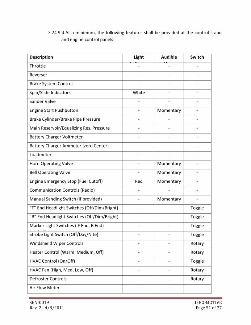
SPN-0019 LOCOMOTIVE Rev. 2 - 4/8/2011 Page 51 of 77
3.24.9.4 At a minimum, the following features shall be provided at the control stand
and engine control panels:
Description Light
Indicator
Audible
Alarm
Switch
Throttle - - -
Reverser - - -
Brake System Control - - -
Spin/Slide Indicators White - -
Sander Valve - - -
Engine Start Pushbutton - Momentary -
Brake Cylinder/Brake Pipe Pressure - - -
Main Reservoir/Equalizing Res. Pressure - - -
Battery Charger Voltmeter - - -
Battery Charger Ammeter (zero Center) - - -
Loadmeter - - -
Horn Operating Valve - Momentary -
Bell Operating Valve - Momentary -
Engine Emergency Stop (Fuel Cutoff) Red Momentary -
Communication Controls (Radio) - - -
Manual Sanding Switch (if provided) - Momentary -
“F” End Headlight Switches (Off/Dim/Bright) - - Toggle
"B" End Headlight Switches (Off/Dim/Bright) - - Toggle
Marker Light Switches ( F End, B End)
(On/Off)
- - Toggle
Strobe Light Switch (Off/Day/Nite) - - Toggle
Windshield Wiper Controls - - Rotary
Heater Control (Warm, Medium, Off) - - Rotary
HVAC Control (On/Off) - - Toggle
HVAC Fan (High, Med, Low, Off) - - Rotary
Defroster Controls - - Rotary
Air Flow Meter - - -
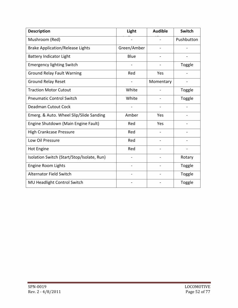
SPN-0019 LOCOMOTIVE Rev. 2 - 4/8/2011 Page 52 of 77
Description Light
Indicator
Audible
Alarm
Switch
Mushroom (Red) - - Pushbutton
Brake Application/Release Lights Green/Amber - -
Battery Indicator Light Blue - -
Emergency lighting Switch - - Toggle
Ground Relay Fault Warning Red Yes -
Ground Relay Reset - Momentary -
Traction Motor Cutout White - Toggle
Pneumatic Control Switch White - Toggle
Deadman Cutout Cock - - -
Emerg. & Auto. Wheel Slip/Slide Sanding Amber Yes -
Engine Shutdown (Main Engine Fault) Red Yes -
High Crankcase Pressure Red - -
Low Oil Pressure Red - -
Hot Engine Red - -
Isolation Switch (Start/Stop/Isolate, Run) - - Rotary
Engine Room Lights - - Toggle
Alternator Field Switch - - Toggle
MU Headlight Control Switch - - Toggle
SPN-0019 LOCOMOTIVE Rev. 2 - 4/8/2011 Page 53 of 77
3.24.9.5 In addition to the operator’s controls, the following indicators, gauges, and
displays, as a minimum, shall be mounted on or adjacent to the main console:
a) Engine oil pressure
b) Engine water temperature
c) Fuel tank level
d) Voltmeter
e) Hour meter
f) Tachometer
g) Hydraulic oil temperature (if hydraulics provided)
h) Speedometer
i) Hydraulic filter condition indicator light (if hydraulics provided)
3.24.10 Cab Windows:
3.24.10.1 The Locomotive shall maximize the use of glazing to allow a high degree of
visibility for the operator. The cab side windows shall be tinted to minimize
glare and solar heat gain during daytime operations, but shall not restrict
visibility during night time operations.
3.24.10.2 All windows shall be sealed around the entire window perimeter to resist
water penetration under all operating conditions.
a) All windows shall be replaceable from outside of the cab.
3.24.11 Cab Windshields:
3.24.11.1 The cab windshield(s) shall comply with FRA Type 1 level certification for
ballistic and large object impacts per 49 CFR Part 223.
3.24.11.2 Visible glare or reflections on the windshield, including reflections from
interior lighting during night operation shall be minimized.
3.24.11.3 Windshield wipers shall be provided on both the travel and work viewing
glass locations.
SPN-0019 LOCOMOTIVE Rev. 2 - 4/8/2011 Page 54 of 77
3.24.11.4 Windows that have windshield wipers shall be manufactured from fully
tempered clear safety glass or laminated safety glass.
3.24.12 Operator’s Cab Side Windows:
3.24.12.1 The Contractor shall provide split sliding sash side windows and fixed
windows on each side of the cab, in accordance with applicable FRA regulations
per 49 CFR 227 and AAR recommended practices. The sliding sash shall be easy
to operate and capable of being secured at any desired horizontal opening
position.
3.24.13 Sun Visor:
3.24.13.1 A tinted, adjustable, heavy duty sun visor shall be provided in the operator’s
cab. The sun visor shall have the capability of pivoting to shade either side
window or a separate provision can be made to accomplish this.
3.24.14 Windshield Washer:
3.24.14.1 A windshield washer system shall be installed to enable the operator to
eject onto the windshield a cleaning and anti-freezing agent of a standard type,
normally used in automotive practice.
3.24.14.2 The washer fluid reservoir shall have a capacity of not less than one (1)
gallon and be refillable from the exterior.
3.25 LIGHTING
3.25.1 Source power for all lighting shall be from the low voltage system.
3.25.2 Headlight, strobe light fixtures and lamps shall be readily serviceable from the
exterior of the Locomotive. Steps/handholds shall be provided as necessary to
access fixtures for maintenance. All lighting fixtures shall be weathertight.
3.25.3 Headlights:
3.25.3.1 Headlights shall be provided at both ends of each Locomotive utilizing fixtures
with sealed beam lamps. Should one (1) lamp fail, the other shall operate at its
nominal voltage and performance.
3.25.3.2 Headlights shall conform to the requirements of 49 CFR 229.125 for intensity
and shall be Xenon high intensity US Reflector Worklamp Headlights Model X-
4500 or WMATA approved equal.
SPN-0019 LOCOMOTIVE Rev. 2 - 4/8/2011 Page 55 of 77
3.25.3.3 Headlight fixtures shall be adjustable for horizontal and-vertical alignment,
and shall be provided with a locking device and Pyrex or equal glass lens.
3.25.3.4 Headlights shall be wired for operation in either direction, and provided with
"OFF-DIM-BRIGHT" controls on the operator’s console for each set of
headlights.
3.25.4 Strobe Lights:
3.25.4.1 Pulsating type strobe lights shall be provided on each end of the Locomotive.
3.25.5 Walkway, Step and Ground Lights:
3.25.5.1 Recessed, weathertight boarding light fixtures shall be provided, for indirect
lighting at the steps.
3.25.5.2 Ground lights shall illuminate the ground area immediately below the cab
side window on both sides of the Locomotive.
3.25.6 Cab Lights:
3.25.6.1 Cab lights shall conform to the requirements of 49 CFR 229.127.
3.25.6.2 Two main ceiling lights shall be provided, one (1) each on the right and left
sides of the cab.
3.25.6.3 An on/off switch and dimmer control shall be provided on the operator’s
console to control each fixture.
3.25.7 Engine Room Lighting:
3.25.7.1 Each Locomotive shall be provided with engine room lighting as follows:
a) Engine room lighting fixtures shall conform to the requirements of 49 CFR-
229.127 and shall be adequately protected, easily serviceable, powered from
the 74 VDC low voltage system.
b) Engine room lighting shall be controlled by a switch in the cab.
SPN-0019 LOCOMOTIVE Rev. 2 - 4/8/2011 Page 56 of 77
3.25.8 Emergency Lighting:
3.25.8.1 The following lights shall remain functional for at least one hour from battery
power supply:
a) Operator’s cab local lighting and indicators;
b) All exterior travel lights, and
c) 50% of all exterior work lights equally distributed around the perimeter.
3.26 HEATING, VENTILATION, AND AIR CONDITIONING
3.26.1 The HVAC system shall consist of heating, ventilation and air conditioning of the
operator’s cab. The HVAC system, including all equipment and components
defined herein shall be service-proven in similar transit applications.
3.26.2 Interior temperatures shall be thermostatically controlled through operator
adjustment, such that at maximum heating conditions, a temperature of 68 F
can be sustained and at maximum cooling conditions, a temperature of 85 F can
be sustained.
3.26.3 The HVAC system shall consist of an independent modular unit. Each modular
unit shall be fastened to the equipment structure in a way that can allow removal
and replacement should any major repairs or overhaul work be required, it shall
be vibration isolated from the cab structure.
3.26.4 In addition to the modular air conditioning unit, floor heating defrosting units
shall be provided for the operator’s cab; one per windshield with wiper location
(up to four).
3.26.5 The HVAC system in the operator’s cab shall allow for a minimum of two (2) air
flow settings plus the ability for the operator to turn the system off completely.
The operator’s auxiliary floor heater defroster units shall be controlled
independently from the operator’s HVAC module.
SPN-0019 LOCOMOTIVE Rev. 2 - 4/8/2011 Page 57 of 77
3.26.6 Maintenance:
3.26.6.1 It is intended that routine maintenance be performed while the units are on
the Locomotive. Periodic maintenance tasks and minor repairs shall be possible
with minimum additional work from the maintenance personnel. Equipment
design and installation shall provide full accessibility for maintenance, trouble-
shooting and repair without interference with other systems.
3.26.6.2 Overhaul and major repairs shall be done after removing the units from the
Locomotive. The removal of a unit from the vehicle shall be straight forward
and take a minimal amount of time to complete.
3.27 PNEUMATIC SYSTEM REQUIREMENTS
3.27.1 The pneumatic air system shall have an air dryer and a manual drain for
condensation on the tank.
3.27.2 The air tanks shall have a pressure relief valve to control over-pressure build-up
within the tank.
3.27.3 All pneumatic hose connection couplings shall be made of stainless steel to
prevent corrosion.
3.27.4 Air Hoses:
3.27.4.1 All flexible connections on the trucks, including those on the brake cylinders,
between carbody shall be made with hoses. All air hoses shall conform to AAR
M-618, with AAR approved reusable fittings meeting AAR M-927.
3.27.5 Air Brake Pipe and Fittings:
3.27.5.1 Air brake pipe and fittings shall be in accordance with the latest AAR
standards for freight brake equipment. Glad hand fittings shall be provided at
each end of the Locomotive.
3.27.5.2 Air piping on trucks shall be black pipe or other approved finish open hearth,
extra heavy, welded steel pipe conforming to ASME A-53. All air hose fittings
shall be cast malleable iron conforming to ANSI B.16.3 with an approved finish
or WMATA approved equal. Pipes shall be free of imperfections such as burrs
and sharp edges. All pipes shall be blown out with dry compressed air and
capped at the time of assembly.
SPN-0019 LOCOMOTIVE Rev. 2 - 4/8/2011 Page 58 of 77
3.27.5.3 Brake piping shall be adequately supported to withstand vibration
encountered on the WMATA System with approved bolted clamps or other
approved means. No pipe shall be left unsupported for lengths greater than 8’.
All pipes and fittings shall be arranged to assure moisture drainage into
reservoirs installed at the lowest points in the system.
3.27.6 Air Reservoirs:
3.27.6.1 The Locomotive shall have a main reservoir and a supply reservoir with a
volumetric capacity capable of supplying the air brake system, to make five (5)
consecutive full-service braking applications and releases at full load, with a full
crew, without initiating an emergency application due to low air. After the five
(5) consecutive full-service braking applications, it must be possible to make an
emergency application. It shall be assumed that compressor loss occurs when
the main reservoir air is at the cut in pressure setting of the air compressor
control. The reservoir sizing calculations shall be submitted to WMATA for
approval and shall consider all WMATA temperature conditions.
3.27.6.2 Only braking air shall be supplied by the supply reservoir, and all other air
requirements shall be taken from the main reservoir. The air supply to the
supply reservoir shall be protected by a check valve. Reservoirs shall conform
to ASME pressure vessel code and stamped with ASME certification. Reservoirs
shall be low alloy steel with flange fittings and coated with a WMATA approved
system inside and outside to resist corrosion.
3.27.6.3 The main reservoir shall be provided with a manual drain valve. The drain
cock shall be installed to open by a pull toward the nearest side of the
Locomotive. The supply reservoir shall be provided with a manual drain plug.
Drain valves and any similar fittings on the bottom of reservoirs shall be
provided with protective shrouds to prevent their being knocked off by debris
on the track.
SPN-0019 LOCOMOTIVE Rev. 2 - 4/8/2011 Page 59 of 77
3.27.7 Air Compressor:
3.27.7.1 An air compressor, sized to meet the specified performance requirements,
shall be provided to supply air to the air brake system and any other auxiliary
system(s). The inlet air filter shall be sized such that the replacement interval is
greater than three (3) months. The air compressor shall be chosen, taking into
consideration the highest ambient operating temperature for the Locomotive,
including slow moving operation in the WMATA tunnels, including heat
generated by the locomotive equipment, including the engine, traction
alternator, compressor, HVAC unit, etc. The compressor configuration and
power supply shall be submitted to WMATA for approval.
3.27.7.2 A regenerating-type air dryer, twin tower design, shall be provided. The dryer
shall have adequate capacity to reduce the relative humidity of the compressed
air to 35 percent at working pressure under all ambient conditions specified in
Section 3.2, throughout the desiccant's minimum one (1) year life.
Replacement desiccant for dryers shall be available in bulk, prepackaged bags
or other suitable containers from multiple sources. The dryer shall be located
for replacement of the desiccant without removing any other equipment on the
Locomotive.
3.28 HYDRAULIC SYSTEM REQUIREMENTS (IF PROVIDED)
3.28.1 All fittings and hose shall be JIC fittings and two wire braided hose minimum
(SAE 100R2 AT) metric fittings. Plastic hoses are not acceptable.
3.28.2 The hydraulic system shall be equipped with oil coolers and thermostatic
controlled fans that will maintain the hydraulic oil temperature range (as
recommended by equipment manufacturer) under heavy usage in extreme
ambient temperatures.
3.28.3 The hydraulic system shall be equipped with a pump suitably sized for the
application.
3.28.4 Pressure and return line filtration shall be provided in the hydraulic system with
minimum filtration of 10-micron.
3.28.5 The piping shall be equipped with quick disconnect hydraulic system diagnostic
checkpoints.
3.28.6 The hydraulic system shall have a hydraulic oil level sight gauge located on the
hydraulic tank.
SPN-0019 LOCOMOTIVE Rev. 2 - 4/8/2011 Page 60 of 77
3.28.7 The hydraulic system shall have a remote hydraulic oil drain.
3.28.8 In an event of the loss of hydraulic system pressure, an electric emergency pump
shall be provided.
3.28.9 The Locomotive shall have a manual filtered hydraulic tank fill system.
3.29 RADIO
3.29.1 Provisions shall be made within the cab for mounting, by the Contractor, of a
transit vehicle AAR Radio with separate speaker, separate microphone and an
exterior antenna. The Contractor shall furnish a source of 12 VDC power as
described in Section 3.19.15 through a circuit breaker rated at 3 AMPS for the
control circuit and 40 AMPS for the transmitter.
3.29.2 The Radio System shall be of the "clean cab" design and meet all AAR Standards.
3.29.3 The Radio provided by the Contractor shall be a Motorola Astro XTL 5000 digital
mobile radio standard for the WMATA Communication System. The remote
control head shall have a minimum of eight (8) frequency allocations. An external
transmit/receive antenna shall be cab roof mounted and shall be a Sinclair 221
LP, or WMATA approved equal. Each unit shall have a db spectra, UHF varilator,
Model Number ACV2501JIMO.
3.30 MANUALS AND DOCUMENTATION
3.30.1 The Contractor shall provide ten (10) sets of Operation and Maintenance
Manuals and four (4) complete sets (assembly drawings) of full size blue prints
for all Locomotive equipment and systems including but not limited to:
a) Fuel System,
b) Lubricating Oil System,
c) Cooling System,
d) Engine / Engine Controls,
e) Compressed Air System,
f) Heating, Ventilating, and Air Conditioning,
g) Truck Assembly,
h) Electrical Systems,
SPN-0019 LOCOMOTIVE Rev. 2 - 4/8/2011 Page 61 of 77
i) Propulsion System, including dynamics brakes,
j) Carbody,
k) Cab / Cab Equipment,
l) Couplers,
m) Radio.
3.30.2 Manuals shall contain complete and easily read diagrams of all systems on the
locomotives and shall employ American standard symbols and notations.
3.30.3 Manuals shall contain 8-1/2" x 11" pages. The binders shall not exceed 3" overall
thickness. Punched holes shall be on 3/4" centers. Folding pages will be
permitted (11" x 17", "Z” folded) where the information to be conveyed cannot
be presented clearly on single pages. Manuals for 8-1/2" x 11" pages may be
divided into Book 1, Book 2, etc., if the required material cannot be
accommodated within the maximum binder thickness. A complete Table of
Contents shall be provided in each book.
3.30.4 All sections shall be sub-divided, to the extent required by the subject matter,
into the following topics:
a) Detailed Locomotive Layout Drawings
b) General Subsystems Description and Operation
c) Block Diagram
d) Signal Floor Diagrams
e) Functional Schematics
f) Functional Wiring or piping Diagrams
g) Troubleshooting Techniques
h) Lubrication and Cleaning, including frequency, methods and trade
identifications of recommended materials; component locating and description.
The Locomotive shall incorporate in the operator’s cab where possible, a metal
etched pictorial placard designating lubrication points, indicating types of
lubricant, location on the Locomotive, and frequency of checking or changing
lubricants.
SPN-0019 LOCOMOTIVE Rev. 2 - 4/8/2011 Page 62 of 77
i) Inspection and Maintenance Standards, Including Wear Limits, Settings and
Tolerances
j) Installation and Removal of subject matter
k) Test and Evaluation Procedures
l) Recommended Overhaul
3.30.5 All parts shall be identified and cataloged within each individual system.
3.30.6 The Material Safety Data Sheets (MSDS) for all materials shall be supplied.
3.30.7 Manuals shall contain a complete list of OEM part numbers for all consumable
replacement items including replacement filters and drive belts, and other high
wear items. OEM reliability data and documentation for manufacturers’
recommended scheduled maintenance requirements for all major components,
assemblies and subassemblies will be provided as an integral part of the manuals.
3.30.8 Wiring diagrams related to on-board diagnostics and automated components
shall identify critical test points and corresponding electrical values.
3.30.9 Pneumatic and hydraulic diagrams shall identify critical test points with
corresponding pressure / temperature values.
3.30.10 Manuals shall contain fault tree and problem / cause style troubleshooting
guides for electrical, pneumatic, and hydraulic systems.
3.31 MAINTENANCE SPARES
3.31.1 As soon as the equipment designs become finalized, the Contractor shall provide
a list of recommended Maintenance Spares that should be held by WMATA for
the ongoing maintenance of the Locomotive. The Maintenance Spares shall
include consumables, casualty replacements, and maintenance float. As a
minimum, the following information shall be furnished for each item on the
Maintenance Spares list:
a) A supplier part number;
b) Description;
c) Recommended quantity;
d) Estimated annual consumption (for consumable spares);
SPN-0019 LOCOMOTIVE Rev. 2 - 4/8/2011 Page 63 of 77
e) Shelf life;
f) Unit price and extended price by vehicle; and
g) Lead time for ordering.
3.31.2 The lead time for each item on the Maintenance Spares list shall take into
consideration the following classifications:
a) Wear – Parts that may be expected to require regular replacement under
normal maintenance schedules, such as mechanical parts subject to
continuous operation.
b) Consumables – Parts, including fluids, with an expected life of less than five (5)
years.
c) One Shot – Parts that normally require replacement after performing their
function one time, such as fuses.
d) Long Lead – Parts that are not readily available from distributors or the
manufacturer.
e) Exchange Assemblies – Assemblies that will be exchanged with failed units (or
units that are not responding as specified) on the supplied equipment and that
must be inventoried as complete assemblies.
4.0 Inspection and Acceptance Testing
4.1 INITIAL INSPECTION
4.1.1 WMATA representatives may inspect the equipment at the manufacturing facility
at any time during the manufacturing period. In addition, WMATA
representatives may perform onsite testing and acceptance at the manufacturing
facility at key milestones of the manufacturing process and before delivery to
WMATA.
4.1.2 The Locomotive shall be inspected upon delivery. The Locomotive shall be
completely lubricated and serviced with all equipment installed for immediate
operation, except for fuel. Water cooled engines are to be protected from freeze
up by a 50/50 solution of ethylene glycol base anti-freeze (rust inhibitive type)
unless otherwise specified, and the radiator marked or tagged to show the
manufacturer and type of coolant used, and actual protection afforded.
SPN-0019 LOCOMOTIVE Rev. 2 - 4/8/2011 Page 64 of 77
4.2 ACCEPTANCE TESTING
4.2.1 Upon delivery of the Locomotive, the Contractor shall perform on-rail acceptance
testing at WMATA. Acceptance test plans shall be submitted by the Contractor
ten (10) working days prior to performing the test and approved by WMATA,
prior to testing. As a minimum acceptance tests shall include:
a) System Clearance Checks (within the WMATA System)
b) Full-functions performance testing
c) Tow Capacity Verification
d) Braking Capability Verification
e) Radio Frequency & Power Test
f) Vehicle Lighting Test
g) Heating & Cooling Test
h) Noise Level Measurements
4.2.2 A Contractor's Representative shall place the equipment in service and instruct
WMATA’s operators, mechanics, and supervisors at a location, to be specified by
WMATA (not necessarily at the machine delivery point).
4.2.3 The maintenance training course shall not be concurrent with the equipment
start-up assistance and training.
5.0 Safety Certification
5.1 REQUIREMENTS:
5.1.1 The Contractor shall comply with the U.S. Department of Labor’s Occupational
Safety and Health Administration (OSHA) standards.
5.1.2 The Contractor shall conduct a safety program, which ensures to the greatest
extent possible, that the equipment delivered to WMATA are operationally safe
and secure for passengers, employees, emergency responders, and the general
public.
SPN-0019 LOCOMOTIVE Rev. 2 - 4/8/2011 Page 65 of 77
6.0 Warranty and Reliability
6.1 WARRANTY
6.1.1 All components, parts, and equipment furnished under this contract shall carry a
minimum 12 month (1 year) warranty for parts and labor. Warranty coverage
shall be activated upon acceptance of the Locomotive(s) at WMATA. See Special
Provision 14 (Warranty) for additional warranty provisions.
6.1.2 Pre-Manufactured items installed on the Locomotive will be covered by the OEM
manufacturers’ warranties unless the warranty is less than one (1) year. The
Contractor shall cover all Pre-Manufactured items not covered by OEM
manufacturers’ warranties up to the one (1) year requirement.
6.1.3 Design Life:
6.1.3.1 The Locomotive shall be designed for a 20-year minimum life, operating with
the duty cycle and in the environment as defined in this Specification, without
requiring structural repair or replacement for any reason other than collision
damage, vandalism, natural disasters, or misuse.
6.1.3.2 This requirement shall particularly apply to the carbody structure, truck
structure, and equipment cases. Other equipment may be subject to routine
maintenance, overhaul or replacement as appropriate.
6.1.3.3 The Contractor shall make every effort to minimize life-cycle costs of the
Locomotive.
6.1.4 Spares Parts:
6.1.4.1 Warranty Spares
a) The Contractor shall maintain an adequate stock of Warranty Spare Parts to
replace failed components during the warranty period of one (1) year without
cost to WMATA.
b) Delivery of Warranty Spare Parts to WMATA shall take no longer than 24 hours
from notification by WMATA of a failed component.
6.2 RELIABILITY
SPN-0019 LOCOMOTIVE Rev. 2 - 4/8/2011 Page 66 of 77
6.2.1 Reliability and availability of this equipment is critical. The successful Contractor
is required to provide short notice on-site technical support when required, and
to quickly provide unique parts, assemblies, and subassemblies throughout the
equipment life-cycle.
6.2.2 Definitions
6.2.2.1 Reliability: The probability of performing a specified function without failure
and within design parameters, for the period of operation intended, under
actual operating conditions.
6.2.2.2 Fleet: Vehicles furnished under the terms of this contract.
6.2.2.3 Failure: Any malfunction which requires unscheduled equipment maintenance,
repair, or replacement
6.2.2.4 System: Any group of functionally-interrelated equipment which performs in
concert to produce control of a particular function relating to the performance
of the equipment. The components of a system are dependent on the function
of the apparatus as it performs on the equipment, and may be furnished by one
or more suppliers.
6.2.2.5 Components and Subsystems: Any individual assembly, plug-in module, or
component which is designed to perform a particular function relating to the
operation of a system such as an engine, gear box, air compressor, or friction
brake control unit. For the purpose of reliability testing, a component or
subsystem is to be considered as a component of a system which may require
costly repairs or which, if inoperative, will render the equipment unusable.
6.2.2.6 Prime Failure: A failure which occurs without being related to the failure of
associated items.
6.2.2.7 Chargeable Failure: A chargeable failure of an item is a failure which results in
a loss of function of that item including:
a) A fault of an item while operating within its design and environmental
specification limits.
b) Faults caused by improper operation, maintenance, or testing of the item as a
result of Contractor-supplied documentation.
SPN-0019 LOCOMOTIVE Rev. 2 - 4/8/2011 Page 67 of 77
c) Item degradation discovered during the recommended preventive
maintenance interval which causes the loss of function or near loss of function
of that item (excluding consumable items). NOTE: Due to the subjective nature
of classifying such instances, the discrepant item(s), upon the Contractor’s
request, shall be retained for review on WMATA’s property for a period not to
exceed two (2) weeks.
d) Consumable items requiring replacement for reasons other than normal
wear/aging.
6.2.3 Requirements
6.2.3.1 Failure data from the WMATA maintenance tracking database will be compiled
by WMATA. The Contractor will be provided with a list of the chargeable
failures.
6.2.3.2 The Contractor has the right to request that WMATA review the status of any
failure charged against reliability for compliance with the guidelines. Problems
with claims which cannot be resolved shall be referred to the Contracting
Officer for decision.
6.2.3.3 It shall be the responsibility of the Contractor to closely monitor the failure
modes of all the systems to insure that the vehicles will meet the desired
reliability goals. If at any time during the reliability period, the failure events of
any system exceed the allowable occurrences, it shall be the responsibility of
the Contractor to seek modifications and changes which will bring the system
into compliance, on all vehicles, regardless of whether they have exhibited the
same failure, and regardless of its warranty status.
6.2.3.4 The vehicle shall begin the reliability evaluation period upon formal acceptance
or conditional acceptance by WMATA.
6.2.3.5 The decision on reliability compliance shall be on a system by system basis and
shall rest with the Contracting Officer.
6.2.3.6 The Contractor shall be responsible for performing any modifications required
to bring the vehicle and systems into conformance with these reliability goals.
The Contractor’s responsibility for these modifications shall include all costs for
materials, necessary labor for removal and replacement, and testing associated
with the required corrective action.
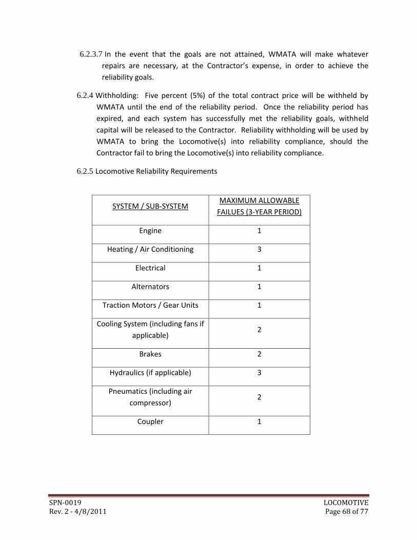
SPN-0019 LOCOMOTIVE Rev. 2 - 4/8/2011 Page 68 of 77
6.2.3.7 In the event that the goals are not attained, WMATA will make whatever
repairs are necessary, at the Contractor’s expense, in order to achieve the
reliability goals.
6.2.4 Withholding: Five percent (5%) of the total contract price will be withheld by
WMATA until the end of the reliability period. Once the reliability period has
expired, and each system has successfully met the reliability goals, withheld
capital will be released to the Contractor. Reliability withholding will be used by
WMATA to bring the Locomotive(s) into reliability compliance, should the
Contractor fail to bring the Locomotive(s) into reliability compliance.
6.2.5 Locomotive Reliability Requirements
SYSTEM / SUB-SYSTEM MAXIMUM ALLOWABLE
FAILUES (3-YEAR PERIOD)
Engine 1
Heating / Air Conditioning 3
Electrical 1
Alternators 1
Traction Motors / Gear Units 1
Cooling System (including fans if
applicable) 2
Brakes 2
Hydraulics (if applicable) 3
Pneumatics (including air
compressor) 2
Coupler 1
SPN-0019 LOCOMOTIVE Rev. 2 - 4/8/2011 Page 69 of 77
7.0 Training
7.1 REQUIREMENTS/DELIVERABLES
7.1.1 The Contractor is responsible for providing:
7.1.1.1 Training in the maintenance and operation of the contracted item(s).
7.1.1.2 Training materials sufficient to support continued in-house WMATA training.
7.1.1.3 Updated training and training materials when, in the scope of the Contract,
changes or modifications are made that affect the operation or maintenance of
the unit(s) contracted for.
7.1.2 Scope of work: Training for the Locomotive will require a minimum of twelve (12)
weeks at 40 hours per week shifts to be designated by WMATA with no premium
rates and two (2) class sessions that consist of 40 hours each for maintenance per
unit delivered.
7.1.3 All training, as described below, shall take place by the Contractor prior to
acceptance of equipment or materials by WMATA. The number of WMATA
employees to be trained will be specified on a contract-by-contract basis.
However, the minimum number shall be four (4) for operation training and
twenty-six (26) for operations and maintenance of equipment or materials by
WMATA. Those persons shall be identified by WMATA.
7.1.3.1 Operations training: Will be tailored specifically to WMATA equipment, and
designed to teach the day to day operations of all equipment. The training will
be sufficient to bring personnel to a level of operating proficiency such that
routine Contractor support is not needed.
7.1.3.2 Maintenance training: Will be subdivided into two major levels:
a) System Level Maintenance Training covering:
1) Theory of operation of the system and its major components
2) System configuration
3) Preventative maintenance, consisting of written procedures and schedules
for the periodic maintenance of all equipment
4) Written and validated inspection procedures and a system - level
troubleshooting guide (to the lowest field - replaceable unit)
SPN-0019 LOCOMOTIVE Rev. 2 - 4/8/2011 Page 70 of 77
b) Shop Level Maintenance Training covering:
1) Detailed theory of operation to module, board, and /or device level
2) Component level troubleshooting and component replacement
3) Testing and alignment procedures of repaired units
7.1.4 Deliverables: WMATA’s Department of Technical Training and Document Control
(TTDC) requires the following non-copyrighted course materials to be delivered
by the Contractor, according to the following specifications:
a) Training Plan containing the data necessary to begin scheduling instruction.
The plan must be submitted to TTDC ten (10) days after NTP. The plan must
address, for approval, a proposed time line that ensures that all deliverables
are approved and training is presented before the equipment is placed into
service.
b) A list of courses and their duration.
c) Recommended class size.
d) Student Qualifications / Prerequisites: For the purpose of course development
and presentation, Contractors should assume all WMATA students are high
school graduates (or equivalent), and that maintenance personnel will possess
the ability to use basic hand tools and electronic test equipment.
e) Instructor Qualifications: A description of instructor qualifications, a resume,
Curriculum Vitae or other description of instructional qualifications must be
submitted to TTDC as part of the Training Plan. The description should
document a thorough knowledge of the subject equipment, an understanding
of the adult learning process and demonstrated experience in vocational
instruction.
f) Instructor’s Guide containing all the information and direction necessary for
the instructor to make an effective presentation. It shall include adequate
guidelines to conduct a comprehensive training program. Individual lessons
within the course will be organized as separate blocks (or modules) which may
be taught as a unit. In some instances, the same standard operating
procedures could be used for train operators, transportation supervisors, and
central control supervisors. The Instructor Guide should contain, at a
minimum:
SPN-0019 LOCOMOTIVE Rev. 2 - 4/8/2011 Page 71 of 77
1) Program Overview
2) A statement of overall program goals
3) Lesson plans (a session by session outline containing the following):
A- Student learning objectives, stated in measurable terms
B- Overview of each lesson
C- Suggested instructional methods/learning activities
D- Required equipment and /or resources
E- Required time for each topic, lesson and course
g) Evaluation device (s) (written and /or practical tests) designed to measure the
extent to which a student has met the learning objectives, with an answer key
for each of the tests developed. Tests should use a multiple choice format,
and have been validated in a pilot course or by some other means agreed to by
TTDC. Whenever possible, a practical hands-on test shall be developed to
demonstrate the transference of skills.
h) Student Manual, to include all materials for the student to interact in the
learning situation. It shall contain, at a minimum:
1) Program overview/introduction.
2) Statement of overall program goals.
3) Learning objectives, stated in measurable terms that specifically describe
desired behaviours or knowledge to be gained.
4) Prose treatment (not outline format) fully developed content presentation,
developed in the same modular format as the Instructor’s Guide.
5) Illustrations, charts, graphics, and duplication of each visual aid used
during course presentation in order to enhance content presentation and
provide a course reference.
6) Problems/questions related to lesson content, as appropriate.
7) Audio-visual aids (handouts, transparencies, slides, films, and computer
presentations). Visual aids are required for each circuit or wiring diagram
and all activities not demonstrable in the classroom.
SPN-0019 LOCOMOTIVE Rev. 2 - 4/8/2011 Page 72 of 77
8) Supplemental materials: A functional mock-up, or a functional
representation, is required of any equipment which requires theoretical
discussion. This may be in the form of an animated schematic, a model of
the equipment, an actual device, an interactive video training device, or a
TTDC - approved substitute. All mock-ups become the property of
WMATA.
7.1.5 Number of Copies: The Contractor shall deliver final copies to WMATA as follows:
a) One (1) complete set of training materials that is in a specified electronic
format or camera ready copy.
b) Five (5) copies of all student and instructor materials, to be used for archival
purpose in the TTDC and Document Center (TDC).
c) A set of complete student materials for each participant enrolled in training
classes.
7.1.6 Delivery of Instruction: All instruction will be presented in accordance with
approved training materials as specified under deliverables.
a) All operator training will be coordinated through WMATA Track &
Structure/System (TSSM) Training.
b) All maintenance training will be coordinated through Car Maintenance (CMNT/
CTEM).
c) All courses will be attended and monitored by TTDC. Unsatisfactory
performance may result in the suspension of the training until such time as the
specified discrepancies are corrected.
d) Operator training shall be performed between 7:00 AM to 3:00 PM for daytime
training and 10:00 PM to 6:00 AM for night time training.
e) Training shall cover safe operation of all systems.
f) All training shall be performed at the location specified by WMATA TSSM and
CMNT.
g) The Trainer must have a minimum of five (5) years of experience on
Locomotive equipment.
SPN-0019 LOCOMOTIVE Rev. 2 - 4/8/2011 Page 73 of 77
h) All operators shall receive a “Certificate of Completion” on the satisfactory
completion of the training.
8.0 Delivery Schedule
8.1 SHIPPING
8.1.1 Equipment shall be constructed, prepared, and loaded so that it will withstand,
without damage, handling likely to be encountered during delivery. Valuable and
easily pilfered parts such as batteries, tools, and loose small items shall be
shipped in such a manner as to resist pilferage.
8.1.2 Delivery of the equipment to WMATA’s Alexandria Yard shall take place 420 days
after Notice to Proceed (NTP), at the following address:
WMATA
3101 Eisenhower Avenue
Alexandria, VA 22314
8.1.3 Contractor shall be responsible for unloading the Locomotive onto the track
designated by WMATA.
8.1.4 Complete operation and maintenance manuals, and assembly drawings shall be
delivered according to the address below as outlined by the following:
a) 365 days after NTP - Two (2) sets of preliminary manuals will be delivered for
review. These preliminary manuals shall not be counted against the ten (10)
operation and maintenance manuals specified in Section 3.30.1.
b) 420 days after NTP – One (1) complete set of manuals will accompany each
Locomotive delivered as the result of this Contract. Manuals will be packaged
in a waterproof container permanently affixed to the body of the Locomotive.
c) The remaining sets of manuals and four (4) complete sets of assembly drawings
shall provided in both hardcopy and a WMATA approved electronic format and
shall be forwarded not later than 420 days after NTP to:
WMATA
Attention: Dan Hagan
5801-B Sunnyside Avenue
Greenbelt, MD 20705
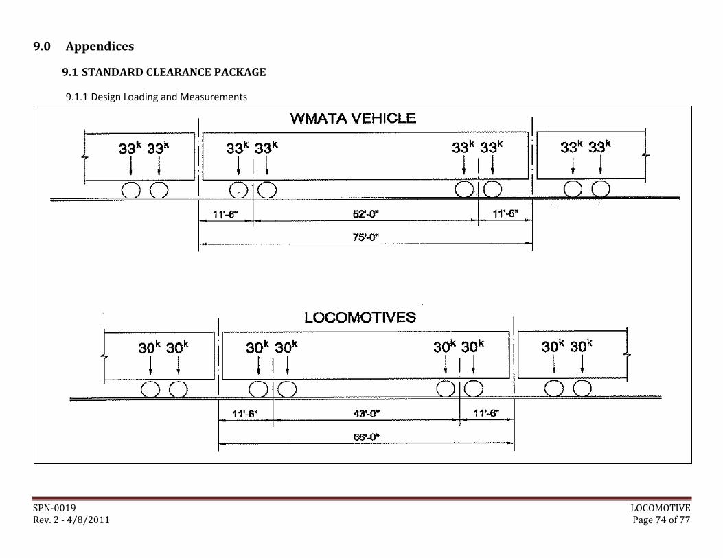
SPN-0019 LOCOMOTIVE Rev. 2 - 4/8/2011 Page 74 of 77
9.0 Appendices
9.1 STANDARD CLEARANCE PACKAGE
9.1.1 Design Loading and Measurements
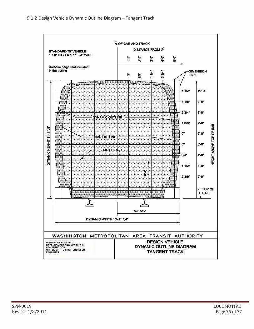
SPN-0019 LOCOMOTIVE Rev. 2 - 4/8/2011 Page 75 of 77
9.1.2 Design Vehicle Dynamic Outline Diagram – Tangent Track
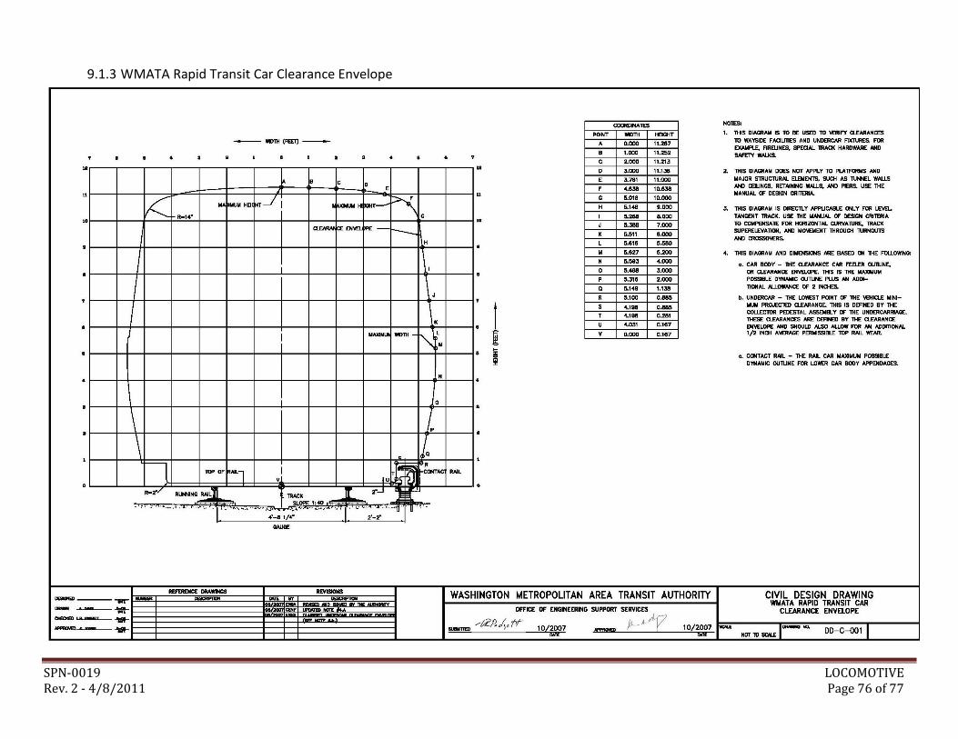
SPN-0019 LOCOMOTIVE Rev. 2 - 4/8/2011 Page 76 of 77
9.1.3 WMATA Rapid Transit Car Clearance Envelope
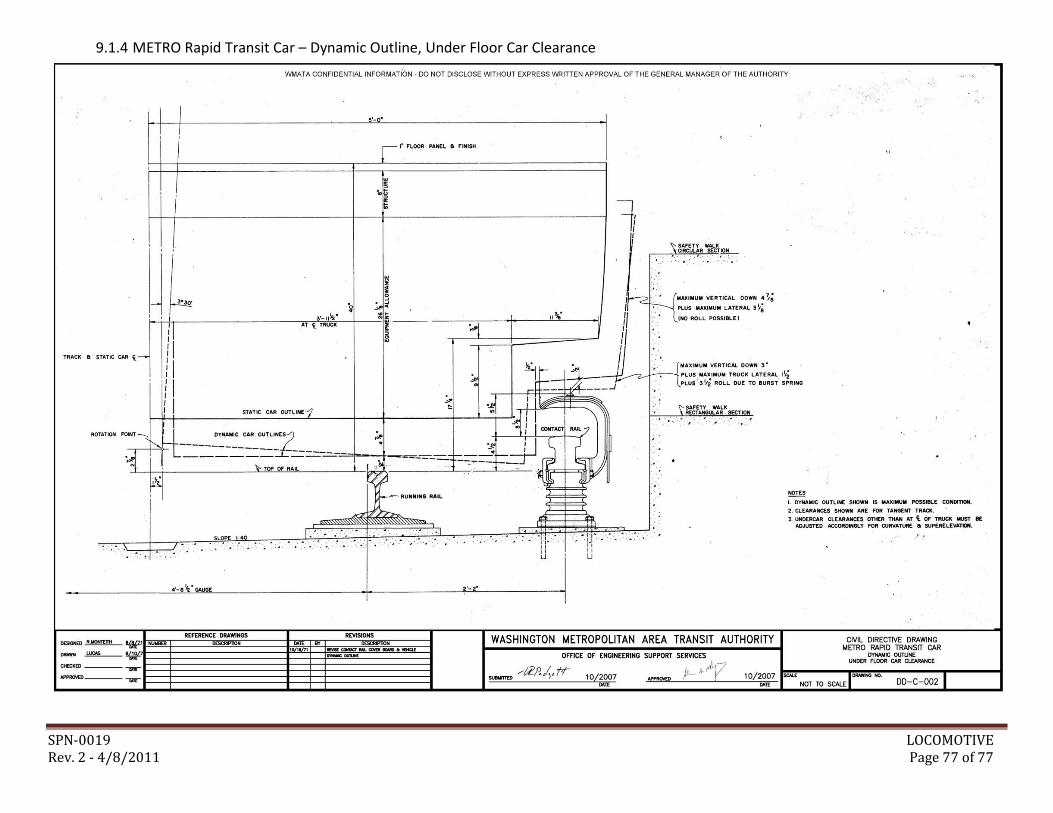
SPN-0019 LOCOMOTIVE Rev. 2 - 4/8/2011 Page 77 of 77
9.1.4 METRO Rapid Transit Car – Dynamic Outline, Under Floor Car Clearance