Embed Size (px)
Citation preview
REGISTRO BRASILEIRO Rules for the Construction and Classification TITLE - MODU
DE NAVIOS E AERONAVES of Mobile Offshore Drilling Units Hull- Part II HULL EQUIPMENT - Section3
RGMODM15EN CHAPTERS - from A to E
MODU RULES 2015 3-1
PART II RULES FOR THE
CONSTRUCTION AND
CLASSIFICATION OF MOBILE
OFFSHORE DRILLING UNITS
TITLE MOBILE OFFSHORE DRILLING
UNITS
SECTION 3 HULL EQUIPMENT
CHAPTERS
A APPROACH
B DOCUMENTS, REGULATIONS AND
STANDARDS
C MATERIALS AND WORKMANSHIP
D SPECIFIC SYSTEM REQUIREMENTS
E FIRE DETECTION, PROTECTION,
PREVENTION AND FIGHTING

REGISTRO BRASILEIRO Rules for the Construction and Classification TITLE - MODU
DE NAVIOS E AERONAVES of Mobile Offshore Drilling Units Hull – Part II HULL EQUIPMENT - Section 3
RGMODM15EN CHAPTERS - from A to E
MODU RULES 2015 3-2
REGISTRO BRASILEIRO Rules for the Construction and Classification TITLE - MODU
DE NAVIOS E AERONAVES of Mobile Offshore Drilling Units Hull- Part II HULL EQUIPMENT - Section3
RGMODM15EN CHAPTERS - from A to E
MODU RULES 2015 3-3
CONTENTS
APPROACH .................................................................... 6
A1. APPLICATION ................................................... 6 100. Nature of the systems ..................................... 6
CHAPTER B .................................................................... 6
DOCUMENTS, REGULATIONS AND
STANDARDS ................................................................... 6
B1. DOCUMENTS TO BE SUBMITTED TO
RBNA 6 100. Documents required ...................................... 6
B2. REGULATIONS AND STANDARDS .............. 6 100. Application .................................................... 6
B3. STANDARDS ....................................................... 6 100. National and International Standards ........... 6
B4. REFERENCES .................................................... 6 100. References ...................................................... 6
MATERIALS AND WORKMANSHIP ........................ 7
C1. MATERIALS ....................................................... 7 100. Material ......................................................... 7
C2. WORKMANSHIP ............................................... 7 100. Application .................................................... 7
CHAPTER D .................................................................... 7
SPECIFIC SYSTEM REQUIREMENTS ..................... 7
D1. LIFTING APPLIANCES AND
PERSONNEL AND PILOT TRANSFER ...................... 7 100. Cranes............................................................ 7 200. Lifting and hoisting equipment ...................... 8 300. Personnel lifts ................................................ 8 400. Personnel and pilot transfer .......................... 8 500. Drilling derricks ............................................ 8 600. Elevating systems for self-elevating units .. 8
D2. ANCHORING, MOORING AND
TOWING .......................................................................... 9 100. Definitions ..................................................... 9 200. Anchoring Systems ......................................... 9 300. Windlasses ................................................... 10 400. Fairleads and Sheaves ................................. 10 500. Anchor line .................................................. 10 600. Anchors ........................................................ 11 700. Quality Control ............................................ 11 800. Control Stations ........................................... 11 900. Towing arrangement .................................... 11
D3. MANOEUVERING SYSTEM .......................... 11 100. Manoeuvering system ................................. 11
D4. LIFE SAVING APPLIANCES (LSA) .............. 11 100. Application .................................................. 11
D5. FIRE FIGHTING EQUIPMENT ..................... 11 SEE CHAPTER E BELOW. ................................................ 11 D6. ACCESS ............................................................. 11
100. Means of access ........................................... 11 200. Safe access to holds, tanks, ballast tanks
and other spaces ...................................................... 12 300. Access manual ............................................. 12 400. General technical specifications .................. 12
D7. REQUIREMENTS FOR HAZARDOUS
AREAS ........................................................................... 13 100. Classification of hazardous areas................ 13
200. Hazardous areas zone 0 ............................... 13 300. Hazardous areas zone 1 ............................... 13 400. Hazardous areas zone 2 ............................... 14 500. Openings, access and ventilation
conditions affecting the extent of hazardous areas .. 14 600. Ventilation of hazardous spaces .................. 15
D8. EMERGENCY CONDITIONS DUE TO
DRILLING OPERATIONS .......................................... 15 100. Emergency conditions due to drilling
operations ................................................................ 15 D9. HULL ACCESSORIES AND FITTINGS ........ 15
100. Handrails ..................................................... 15 200. Bulwark ........................................................ 16 300. Gangways – Surfaces ................................... 16 400. Helideck safety net ....................................... 16 500. Freeing ports ............................................... 16
CHAPTER E .................................................................. 17
FIRE PROTECTION, FIRE DETECTION AND
FIRE EXTINCTION ..................................................... 17
E1. GENERAL ......................................................... 17 100. Application................................................... 17
E2. STRUCTURAL FIRE PROTECTION ............ 17 100. Application................................................... 17
E3. PROTECTION OF
ACCOMMODATION SPACES, SERVICE
SPACES AND CONTROL STATIONS ....................... 21 100. Protection of accommodation spaces,
service spaces and control stations ......................... 21 E4. MEANS OF ESCAPE ........................................ 23
100. Means of escape ........................................... 23 E5. FIRE SAFETY SYSTEMS ................................ 24 E6. EMERGENCY ESCAPE BREATHING
DEVICES ....................................................................... 24 100. EEBD ........................................................... 24
E7. FIRE PROTECTIN AND EXTINCTION ....... 25 100. Fire plan contents ........................................ 25
E8. FIRE PUMPS, FIRE MAINS,
HYDRANTS AND HOSES ........................................... 25 100. Water fire fighting system ............................ 25
E9. FIRE-EXTINGUISHING SYSTEMS .............. 27 100. Fire extinguishing arrangement in
machinery spaces and in spaces containing fired
processes.................................................................. 27 200. Fixed fire extinguishing systems on drilling
and areas ................................................................. 27 300. Fixed fire extinguishing systems on mud
processing area ....................................................... 27 E10. PORTABLE FIRE EXTINGUISHERS IN
ACCOMMODATION, SERVICE AND
WORKING SPACES .................................................... 27 100. Portable fire extinguishers........................... 27
E11. FIRE DETECTION AND ALARM
SYSTEM ......................................................................... 29 100. General ........................................................ 29 200. Machinery spaces ........................................ 29 300. Accommodation and service spaces ............ 29 400. Electrical rooms and control stations .......... 29 500. Drilling and mud processing areas ............. 29 600. Manually operated alarm system ................. 29 700. General alarms ............................................ 29 800. Unnatended machinery spaces and remote
control 29
REGISTRO BRASILEIRO Rules for the Construction and Classification TITLE - MODU
DE NAVIOS E AERONAVES of Mobile Offshore Drilling Units Hull – Part II HULL EQUIPMENT - Section 3
RGMODM15EN CHAPTERS - from A to E
MODU RULES 2015 3-4
900. Mud system level alarms .............................. 29 E.12 FLAMMABLE GAS DETECTION AND
ALARM SYSTEM ......................................................... 30 100. Fixed automatic gas detection and alarm
system 30 200. Areas for protection ..................................... 30 300. Alarms.......................................................... 30 400. Portable combustible gas detectors ............. 30
E13. HYDROGEN SULPHIDE DETECTION
AND ALARM SYSTEM ............................................... 30 100. Fixed automatic hydrogen sylphide gas
detection system ....................................................... 30 200. Areas for protection ..................................... 30 300. Alarms.......................................................... 30 400. Portable hydrogen sulphide gas detectors ... 30 600. Alarms and public address:general alarms . 31 700. Alarms and public address: mud system
level alarms ............................................................. 31 800. Ventilation system alarm ............................ 31 900. Public address ............................................. 31
E14. FIRE-FIGHTERS’ OUTFITS .......................... 31 100. Fire-fighters outfit ....................................... 31
E15. RECHARGING OF AIR CYLINDERS ........... 31 100. Recharging of air cylinders ......................... 31
E16. ARRANGEMENTS IN MACHINERY
AND WORKING SPACES ........................................... 32 100. Arrangements in machinery and working
spaces 32 E17. PROVISIONS FOR HELICOPTER
FACILITIES .................................................................. 32 100. Helicopter facilities ..................................... 32
E18. STORAGE OF GAS CYLINDERS .................. 34 100. Gas cylinders ............................................... 34
E19. FIRE CONTROL PLAN ................................... 34 100. Fire control plan .......................................... 34
E20. OPERATIONAL READINESS AND
MAINTENANCE .......................................................... 34 100. Functional provisions .................................. 34

REGISTRO BRASILEIRO Rules for the Construction and Classification TITLE - MODU
DE NAVIOS E AERONAVES of Mobile Offshore Drilling Units Hull- Part II HULL EQUIPMENT - Section3 RGMODM15EN CHAPTERS - from A to E
MODU RULES 2015 3-5
REGISTRO BRASILEIRO Rules for the Construction and Classification TITLE - MODU
DE NAVIOS E AERONAVES of Mobile Offshore Drilling Units Hull – Part II HULL EQUIPMENT - Section 3 RGMODM15EN CHAPTERS - from A to E
MODU RULES 2015 3-6
CHAPTER A
APPROACH
CHAPTER CONTENT
A1. APPLICATION
A1. APPLICATION
100. Nature of the systems
101. This section applies to hull equipment, system,
lifting appliances and to fire detection, prevention,
protection and fighting.
102. This section applies to all units, except where
specifically mentioned.
CHAPTER B
DOCUMENTS, REGULATIONS AND
STANDARDS
CHAPTER CONTENTS
B1. DOCUMENTS TO BE SUBMITTED TO
RBNA
B2. REGULATIONS
B3. STANDARDS
B1. DOCUMENTS TO BE SUBMITTED TO
RBNA
100. Documents required
101. The plans and documents required for this
Chapter are in Part I, Title 01, Section 2, Chapter C,
Subchapter C1 of the Rules.
B2. REGULATIONS AND STANDARDS
100. Application
101. The Regulations applicable to this Chapter are
in Part I, Title 01, Section 2, Chapter B of the Rules.
B3. STANDARDS
100. National and International Standards
101. Whenever there are not specific requirements
in the Rules related to any system, the National and
International standards are to be researched and applied.
B4. REFERENCES
100. References
101. References for this Section are:
- IMO CODE FOR THE CONSTRUCTION
AND EQUIPMENT OF MOBILE
OFFSHORE DRILLING UNITS (MODU
CODE)
- IACS UR D – REQUIREMENTS
CONCERNING MOBILE OFFSHORE
DRILLING UNITS
- API SPECIFICATION 2C –
SPECIFICATION FOR OFFSHORE
PEDESTAL MOUNTED CRANES
- RBNA GUIDE FOR SHIPBOARD LIFTING
APPLIANCES
- RBNA GUIDE FOR ENTRANCE INTO
CONFINED SPACES
- RBNA GUIDE FOR TOWING
- RBNA SHIP RULES
- BRAZILIAN DPC (MARITIME
AUTHORITY) REGULATIONS NORMAM
01 Chapter 9 Section I
- BRAZILIAN MINISTRY OF LABOUR
NR29
- IMO RESOLUTION MSC.133(76),
TECHNICAL PROVISIONS FOR MEANS
OF ACCESS FOR INSPECTIONS
- IMO
RESOLUTIONA.864(20).RECOMMENDATI
ONS FOR ENTERING ENCLOSED SPACES
ABOARD SHIPS.
- IMO MSC.1 CIRC/1331 - GUIDELINES
FOR CONSTRUCTION, INSTALLATION,
MAINTENANCE AND
INSPECTION/SURVEY OF MEANS OF
EMBARKATION AND
DISEMBARKATION
REGISTRO BRASILEIRO Rules for the Construction and Classification TITLE - MODU
DE NAVIOS E AERONAVES of Mobile Offshore Drilling Units Hull- Part II HULL EQUIPMENT - Section3 RGMODM15EN CHAPTERS - from A to E
MODU RULES 2015 3-7
CHAPTER C
MATERIALS AND WORKMANSHIP
CHAPTER CONTENTS
C1. MATERIALS
C2. WORKMANSHIP
C1. MATERIALS
100. Material
101. Unless otherwise specified, the Requirements
are intended for units to be constructed of hull structural
steel, manufactured and having the properties as
specified in the Ship Rules Part III Title 61 Section 3.
C2. WORKMANSHIP
100. Application
101. The application of the Rules takes for granted
the adequate qualification and expertise of the
manlabour to carry out the operation of the systems
herein described.
CHAPTER D
SPECIFIC SYSTEM REQUIREMENTS
CHAPTER CONTENTS
D1. LIFTING APPLIANCES AND PERSONNEL
AND PILOT TRANSFER
D2. ANCHORING, MOORING AND TOWING
D3. MANOEUVERING SYSTEMS
D4. LIFE SAVING APPLIANCES (LSA)
D5. FIRE DETECTION, PREVENTION,
PROTECTION AND FIGHTING
D6. HULL OPENING: MEANS OF
PROTECTION AND CLOSURE
D7. HULL ACCESSORIES AND FITTINGS
D1. LIFTING APPLIANCES AND
PERSONNEL AND PILOT TRANSFER
100. Cranes
101. Each crane, including its supporting structure,
which is used for the transfer of material, equipment or
personnel between the unit and attending vessels shall be
of a design and construction to the satisfaction of the
RBNA and adequate for the service intended in
accordance with the requirements of the RBNA Guide for
Shipboard Lifting Appliancesand with National or
International Standards or Codes, in particular the API
Specification 2C – Specification for Offshore Pedestal
Mounted Cranes.
102. Cranes shall be so located and protected as to
reduce to a minimum any danger to personnel, due regard
being paid to moving parts or other hazards. Their design
shall have regard to the materials used in construction, the
working conditions to which they will be subjected and
the environmental conditions. Adequate provisions shall
be made to facilitate cleaning, inspection and
maintenance.
103. Consideration shall be given to the failure mode
for each crane in the event of extreme overload so that the
crane operator is exposed to minimum danger.
104. ARBNA surveyorshall survey the installation of
each crane, with particular regard to its supporting
structure.
105. After each crane has been erected on board,
and before it is placed in service, operational and load
tests shall be conducted. These tests shall be witnessed
and verified by aRBNAsurveyor. A record of these tests
and other information concerning initial certification
shall be readily available.
REGISTRO BRASILEIRO Rules for the Construction and Classification TITLE - MODU
DE NAVIOS E AERONAVES of Mobile Offshore Drilling Units Hull – Part II HULL EQUIPMENT - Section 3 RGMODM15EN CHAPTERS - from A to E
MODU RULES 2015 3-8
106. Each crane shall be examined at intervals not
exceeding 12 months. It shall be further tested and
recertified, at intervals not exceeding five years, or after
substantial alteration or repairs. These tests shall be
witnessed and verified by an officer of the RBNA or a
duly authorized person or organization. A record of
these examinations, tests and certifications shall be
readily available.
Guidance
For Brazilian Flag units, see NR29.
Reference is made to the RBNA Guide for Lifting
Appliances and the API Specification 2C.
Reference is made to ILO C32 and ILO C152 –
Occupational safety and health (Dock workers),
Recomendation 160 (Cargo Gear Register Book).
End of guidance
107. Cranes used for loading and discharging of
offshore supply vessels shall be furnished with rating
tables or curves which take into account the dynamics
associated with the unit‟s and vessel‟s motions.
108. Except when loads are determined and marked
prior to lifting, each crane shall be fitted, to the
satisfaction of the RBNA, with a safety device to give
the crane operator a continuous indication of hook load
and rated load for each radius. The indicator shall give a
clear and continuous warning when approaching the
rated capacity of the crane.
109. The RBNAshall give consideration to the
installation of limit switches to provide for the safe
operation of the crane.
110. A crane manual shall be provided for each
crane and shall be readily available. This manual shall
contain full information concerning:
a. design standard, operation, erection, dismantling
and transportation;
b. all limitations during normal and emergency
operations with respect to safe working load, safe
working moment, maximum wind, maximum heel
and trim, design temperatures and braking systems;
c. all safety devices;
d. testing of the emergency lowering system for
personnel transfer, if fitted;
e. diagrams for electrical, hydraulic and pneumatic
systems and equipment;
f. materials used in construction, welding procedures
and extent of non-destructive testing; and
g. guidance on maintenance and periodic inspection.
200. Lifting and hoisting equipment
201. All lifting and hoisting equipment, including
its supporting structure, shall be of a design and
construction to the satisfaction of the RBNA and
adequate for the service intended in accordance with the
requirements of the Rules and the RBNA Guide for
Shipboard Lifting Appliancesand with national or
international standards or codes.
202. Information on the rated capacity of all lifting
and hoisting equipment, developed in accordance with
national or international standards or codes, shall be
available on the unit.
300. Personnel lifts
301. Personnel lifts shall be of a design acceptable
to the RBNA and adequate for the service intended.
302. The construction and installation shall be
surveyed by aRBNA surveyor. The inspections shall be
carried out on installation and at intervals not exceeding
12 months and certificates or reports shall be readily
available, in compliance with the RBNA Guide for
Shipboard Lifting Appliances and Natinal Regulations.
See also the references in B4 above.
303. Each lift car in a column of a column-
stabilized unit shall provide for an emergency exit with
an escape ladder in the hoistway.
400. Personnel and pilot transfer
401. All personnel transfer nets or platforms shall
be designed and constructed to the satisfaction of the
RBNA.
402. A personnel transfer net or platform may be
used to satisfy the pilot transfer arrangement required
by SOLAS regulation V/23.
500. Drilling derricks
501. The design of each drilling derrick and its
supporting structure shall be to the satisfaction of the
RBNA. The rated capacity for each reeving shall be
included in the operating manual.
600. Elevating systems for self-elevating units
Machinery
601. Jacking mechanisms should be:
a. arranged so that a single failure of any component
does not cause an uncontrolled descent of the unit;
b. designed and constructed for the maximum
lowering and lifting loads of the unit as specified in
the unit‟s operation manual;
REGISTRO BRASILEIRO Rules for the Construction and Classification TITLE - MODU
DE NAVIOS E AERONAVES of Mobile Offshore Drilling Units Hull- Part II HULL EQUIPMENT - Section3 RGMODM15EN CHAPTERS - from A to E
MODU RULES 2015 3-9
c. able to withstand the forces imposed on the unit
from the maximum environmental criteria for the
unit; and
d. constructed such that the elevation of the leg
relative to the unit can be safely maintained in case
of loss of power (e.g., electric, hydraulic, or
pneumatic power).
e. Control, communication and alarms
602. The elevating system should be operable
from a central jacking control station.
603. The jacking control station should have the
following:
a. audible and visual alarms for jacking system
overload and out-of-level. Units whose jacking
systems are subject to rack phase differential
should also have audible and visual alarms for rack
phase differential; and
b. i nstrumentation to indicate:
i. the inclination of the unit on two horizontal
perpendicular axes;
ii. power consumption or other indicators for
lifting or lowering the legs, as applicable; and
brake release status.
604. A communication system should be provided
between the central jacking control and a location at
each leg.
D2. ANCHORING, MOORING AND TOWING
100. Definitions
101. FOS: means factors of safety
102. Quasi Static Method: Quasi-static load means
the load is applied so slowly that the structure deforms
also very slowly (very low strain rate) and therefore the
inertia force is very small and can be ignored. A
dynamic load, on the other hand, casues a structure to
vibrate and the inertia force is big enough and must be
considered. To be sure that is really quasi static
problem you shall compare eigenfrequency of you
structure with frequency of loading. If eigenfrequency
about ten times grate of loading frequency it may be a
quasi static problem. In another way it is a dynamic
problem.
103. Eigenfrequency:means a system‟s “own”
frequency (“eigen” means “own” in German), resonant
frequency of a system.
104. Dynamic analysis: A dynamic load causes a
structure to vibrate and the inertia force is big enough
and must be considered.
105. Impact:involves a load quickly applied over a
short time duration.
200. Anchoring Systems
201. Plans showing the arrangement and complete
details of the anchoring system, including anchors,
shackles, anchor lines consisting of chain, wire or rope,
together with details of fairleads, windlasses, winches, and
any other components of the anchoring system and their
foundations are to be submitted to the RBNA, in
accordance with Part I, Title 02, Section 2 Chapter C,
Subchapter C1 of the Rules.
202. An analysis of the anchoring arrangements
expected to be utilized in the unit‟s operation is to be
submitted to the RBNA.Among the items to be addressed
are:
a. Design environmental conditions of waves, winds,
currents, tides and ranges of water depth.
b. Air and sea temperature.
c. Ice conditions (if applicable).
d. Description of analysis methodology.
203. The anchoring system shall be designed so that a
sudden failure of any single anchor line will not cause
progressive failure of remaining lines in the anchoring
arrangement.
204. Anchoring system components shall be designed
utilizing adequate factors of safety (FOS) and a design
methodology suitable to identify the most severe loading
condition for each component. In particular, sufficient
numbers of heading angles together with themost severe
combination of wind, current and wave are to be
considered, usually from the same direction, to determine
the maximum tension in each mooring line. When a
particular site is being considered, any applicable cross sea
conditions are also to be considered in the event that they
might induce higher mooring loads.
205. When the Quasi Static Method is applied, the
tension in each anchor line is to be calculated at the
maximum excursion for each design condition defined in
D2.207, combining the following steady state and dynamic
responses of the Unit:
a. steady mean offset due to the defined wind, current,
and steady wave forces;
b. most probable maximum wave induced motions of the
moored unit due to wave excitation.
206. For relatively deep water, the effect from
damping and inertia forces in the anchor lines is to be
considered in the analysis. The effects of slowly varying
REGISTRO BRASILEIRO Rules for the Construction and Classification TITLE - MODU
DE NAVIOS E AERONAVES of Mobile Offshore Drilling Units Hull – Part II HULL EQUIPMENT - Section 3 RGMODM15EN CHAPTERS - from A to E
MODU RULES 2015 3-10
motions are to be included for MODUs when the
magnitudes of such motions are considered to be
significant.
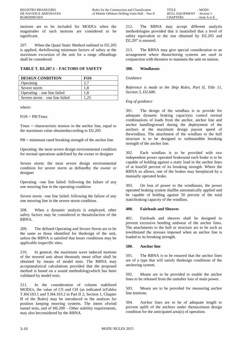
207. When the Quasi Static Method outlined in D2.205
is applied, thefollowing minimum factors of safety at the
maximum excursion of the unit for a range ofheadings
shall be considered:
TABLE T. D2.207.1 – FACTORS OF SAFETY
DESIGN CONDITION FOS
Operating 2,7
Severe storm 1,8
Operating – one line failed 1,8
Severe storm – one line failed 1,25
where:
FOS = PB/Tmax
Tmax = characteristic tension in the anchor line, equal to
the maximum value obtainedaccording to D2.205
PB = minimum rated breaking strength of the anchor line
Operating: the most severe design environmental condition
for normal operations asdefined by the owner or designer
Severe storm: the most severe design environmental
condition for severe storm as definedby the owner or
designer
Operating –one line failed: following the failure of any
one mooring line in the operating condition
Severe storm –one line failed: following the failure of any
one mooring line in the severe storm condition.
208. When a dynamic analysis is employed, other
safety factors may be considered to thesatisfaction of the
RBNA.
209. The defined Operating and Severe Storm are to be
the same as those identified for thedesign of the unit,
unless the RBNA is satisfied that lesser conditions may be
applicable tospecific sites.
210. In general, the maximum wave induced motions
of the moored unit about thesteady mean offset shall be
obtained by means of model tests. The RBNA may
acceptanalytical calculations provided that the proposed
method is based on a sound methodologywhich has been
validated by model tests.
211. In the consideration of column stabilized
MODUs, the value of CS and CH (as indicated inTables
T.H4.103.1 and T.H4.103.2 in Part II 2, Section 1, Chapter
H of the Rules) may be introduced in the analysis for
position keeping mooring systems. The intent ofwind
tunnel tests, and of H6.200 – Other stability requirements,
may also beconsidered by the RBNA.
212. The RBNA may accept different analysis
methodologies provided that it issatisfied that a level of
safety equivalent to the one obtained by D2.205 and
D2.207 is ensured.
213. The RBNA may give special consideration to an
arrangement where theanchoring systems are used in
conjunction with thrusters to maintain the unit on station.
300. Windlasses
Guidance
Reference is made to the Ship Rules, Part II, Title 11,
Section 3, D2.600.
Eng of guidance
301. The design of the windlass is to provide for
adequate dynamic braking capacityto control normal
combinations of loads from the anchor, anchor line and
anchor handlingvessel during the deployment of the
anchors at the maximum design payout speed of
thewindlass. The attachment of the windlass to the hull
structure is to be designed to withstandthe breaking
strength of the anchor line.
302. Each windlass is to be provided with two
independent power operated brakesand each brake is to be
capable of holding against a static load in the anchor lines
of at least50 percent of its breaking strength. Where the
RBNA so allows, one of the brakes may bereplaced by a
manually operated brake.
303. On loss of power to the windlasses, the power
operated braking system shallbe automatically applied and
be capable of holding against 50 percent of the total
staticbraking capacity of the windlass.
400. Fairleads and Sheaves
401. Fairleads and sheaves shall be designed to
prevent excessive bending andwear of the anchor lines.
The attachments to the hull or structure are to be such as
towithstand the stresses imposed when an anchor line is
loaded to its breaking strength.
500. Anchor line
501. The RBNA is to be ensured that the anchor lines
are of a type that will satisfy thedesign conditions of the
anchoring system.
502. Means are to be provided to enable the anchor
lines to be released from the unitafter loss of main power.
503. Means are to be provided for measuring anchor
line tensions.
504. Anchor lines are to be of adequate length to
prevent uplift of the anchors under themaximum design
condition for the anticipated area(s) of operation.
REGISTRO BRASILEIRO Rules for the Construction and Classification TITLE - MODU
DE NAVIOS E AERONAVES of Mobile Offshore Drilling Units Hull- Part II HULL EQUIPMENT - Section3 RGMODM15EN CHAPTERS - from A to E
MODU RULES 2015 3-11
Guidance
Reference is made to the Ship Rules, Part III, Title 61,
Section 3, Chapter B
End of guidance
600. Anchors
601. Type and design of anchors are to be to the
satisfaction of the RBNA.
602. All anchors are to be stowed to prevent
movement during transit.
Guidance
Reference is made to the Ship Rules, Part III, Title 61,
Section 3, Chapter B
End of guidance
700. Quality Control
701. Details of the quality control of the
manufacturing process of the individualanchoring system
components are to be submitted. Components shall be
designed,manufactured and tested in accordance with
recognized standards insofar as possible andpractical.
Equipment so tested shall, insofar as practical, be legibly
and permanentlymarked with the RBNA‟s stamp and
delivered with documentation which records the resultsof
the tests.
Guidance
Reference is made to the Ship Rules, Part III, Title 61,
Section 3, Chapter B
End of guidance
800. Control Stations
801. A manned control station is to be provided with
means to indicate anchor linetensions at the individual
windlass control positions and to indicate wind speed and
direction.
802. Reliable means are to be provided to
communicate between locations critical to theanchoring
operation.
803. Means are to be provided at the individual
windlass control positions to monitoranchor line tension,
windlass power load and to indicate amount of anchor line
payed out.
900. Towing arrangement
901. The design and arrangement of towing fittings
shall have regard to both normal and emergency
conditions.
902. Arrangements, equipment and fittings provided
in accordance with paragraph D2.901 shall meet the
appropriate requirements of the RBNA (*)
(*) Refer to the Guidelines for safe ocean towing
(MSC/Circ.884).
Guidance
Reference is made to the RBNA Guide for Towing.
End of guidance
903. Each fitting or item of equipment provided
under this regulation shall be clearly marked with any
restrictions associated with its safe operation, taking
into account the strength of its attachment to the unit‟s
structure.
D3. MANOEUVERING SYSTEM
100. Manoeuvering system
101. For self-propelled units, see Part II, Title 11,
Section 3, Chapter G of the Ship Rules.
D4. LIFE SAVING APPLIANCES (LSA)
100. Application
101. This subchapter is applicable to all Life Saving
Appliances.
102. The requirements are to be in accordance with
the IMO MODU Code, Chapter 10.
103. For units under the Brazilian Flag, the
requirements of NORMAM 01 Chapter 9 Section IV
apply.
104. For foreign Flag units, National Regulations, if
existing, apply, and in the absecnce of those, the IMO
MODU Code applies.
105. In any case, the requirements shall not be less
stringent than those of the IMO MODU Code.
D5. FIRE FIGHTING EQUIPMENT
See Chapter E below.
D6. ACCESS
100. Means of access
REGISTRO BRASILEIRO Rules for the Construction and Classification TITLE - MODU
DE NAVIOS E AERONAVES of Mobile Offshore Drilling Units Hull – Part II HULL EQUIPMENT - Section 3 RGMODM15EN CHAPTERS - from A to E
MODU RULES 2015 3-12
101. Each space within the unit shall be provided
with at least one permanent means of access to enable,
throughout the life of a unit, overall and close-up
inspections and thickness measurements of the unit‟s
structures to be carried out by the RBNA, the company,
and the unit‟s personnel and others as necessary. Such
means of access shall comply with the provisions of
D6.400 and with the Technical provisions for means of
access for inspections, adopted by the Maritime Safety
Committee by resolution MSC.133(76), as may be
amended by the Organization.
102. Where a permanent means of access may be
susceptible to damage during normal operations or
where it is impracticable to fit permanent means of
access, the RBNA may allow, in lieu thereof, the
provision of movable or portable means of access, as
specified in the Technical provisions, provided that the
means of attaching, rigging, suspending or supporting
the portable means of access forms a permanent part of
the unit‟s structure. All portable equipment shall be
capable of being readily erected or deployed by the
unit‟s personnel.
1,3. The construction and materials of all means of
access and their attachment to the unit‟s structure shall
be to the satisfaction of the RBNA The means of
access shall be subject to inspection prior to, or in
conjunction with, its use in carrying out surveys in
accordance with Part I Title 02 Section 2 of the Rules.
200. Safe access to holds, tanks, ballast tanks and
other spaces
201. Safe access [*] to holds, cofferdams, tanks and
other spaces shall be direct from the open deck and
such as to ensure their complete inspection. Safe access
may be from a machinery space, pumproom, deep
cofferdam, pipe tunnel, hold, double hull space or
similar compartment not intended for the carriage of oil
or hazardous materials where it is impracticable to
provide such access from an open deck.
(*) Refer to Recommendations for entering enclosed
spaces aboard ships, adopted by the Organization by
resolution A.864(20).
202. Tanks, and subdivisions of tanks, having a
length of 35m or more, shall be fitted with at least two
access hatchways and ladders, as far apart as
practicable. Tanks less than 35m in length shall be
served by at least one access hatchway and ladder.
When a tank is subdivided by one or more swash
bulkheads or similar obstructions which do not allow
ready means of access to the other parts of the tank, at
least two hatchways and ladders shall be fitted.
203. Each hold shall be provided with at least two
means of access as far apart as practicable. In general,
these accesses shall be arranged diagonally, e.g., one
access near the forward bulkhead on the port side, the
other one near the aft bulkhead on the starboard side.
300. Access manual
301. A unit‟s means of access to carry out overall
and close-up inspections and thickness measurements
shall be described in an access manual which may be
incorporated in the unit‟s operating manual. The
manual shall be updated as necessary, and an updated
copy maintained on board. The structure access manual
shall include the following for each space:
a. plans showing the means of access to the space,
with appropriate technical specifications and
dimensions;
b. plans showing the means of access within each
space to enable an overall inspection to be carried
out, with appropriate technical specifications and
dimensions. The plans shall indicate from where
each area in the space can be inspected;
c. plans showing the means of access within the space
to enable close-up inspections to be carried out,
with appropriate technical specifications and
dimensions. The plans shall indicate the positions
of critical structural areas, whether the means of
access is permanent or portable and from where
each area can be inspected;
d. instructions for inspecting and maintaining the
structural strength of all means of access and
means of attachment, taking into account any
corrosive atmosphere that may be within the space;
e. instructions for safety guidance when rafting is
used for close-up inspections and thickness
measurements;
f. instructions for the rigging and use of any portable
means of access in a safe manner;
g. an inventory of all portable means of access; and
h. . records of periodical inspections and maintenance
of the unit‟s means of access.
302. For the purpose of this paragraph “critical
structural areas” are locations which have been
identified from calculations to require monitoring or
from the service history of similar or sister units to be
sensitive to cracking, buckling, deformation or
corrosion which would impair the structural integrity of
the unit.
400. General technical specifications
401. For access through horizontal openings,
hatches or manholes, the dimensions shall be sufficient
to allow a person wearing a self-contained air-breathing
apparatus and protective equipment to ascend or
descend any ladder without obstruction and also
provide a clear opening to facilitate the hoisting of an
injured person from the bottom of a confined space.
402. The minimum clear opening shall not be less
REGISTRO BRASILEIRO Rules for the Construction and Classification TITLE - MODU
DE NAVIOS E AERONAVES of Mobile Offshore Drilling Units Hull- Part II HULL EQUIPMENT - Section3 RGMODM15EN CHAPTERS - from A to E
MODU RULES 2015 3-13
than 600 mm x 600 mm. When access to a hold is
arranged through a flush manhole in the deck or a
hatch, the top of the ladder shall be placed as close as
possible to the deck or hatch coaming. Access hatch
coamings having a height greater than 900mm shall
also have steps on the outside in conjunction with the
ladder.
403. For access through vertical openings, or
manholes, in swash bulkheads, floors, girders and web
frames providing passage through the length and
breadth of the space, the minimum opening shall be not
less than 600mm x 800mm at a height of not more than
600mm from the bottom shell plating unless gratings or
other footholds are provided.
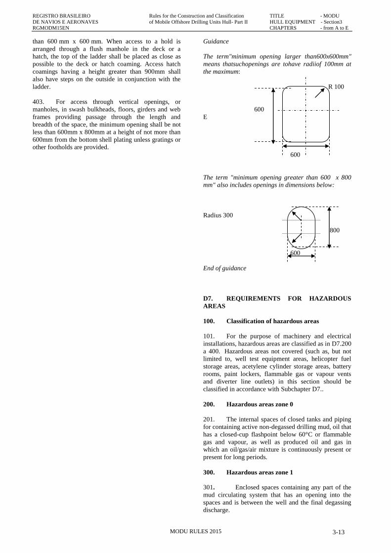
Guidance
The term"minimum opening larger than600x600mm"
means thatsuchopenings are tohave radiiof 100mm at
the maximum:
R 100
600
E
600
The term "minimum opening greater than 600 x 800
mm" also includes openings in dimensions below:
Radius 300
800
600
End of guidance
D7. REQUIREMENTS FOR HAZARDOUS
AREAS
100. Classification of hazardous areas
101. For the purpose of machinery and electrical
installations, hazardous areas are classified as in D7.200
a 400. Hazardous areas not covered (such as, but not
limited to, well test equipment areas, helicopter fuel
storage areas, acetylene cylinder storage areas, battery
rooms, paint lockers, flammable gas or vapour vents
and diverter line outlets) in this section should be
classified in accordance with Subchapter D7..
200. Hazardous areas zone 0
201. The internal spaces of closed tanks and piping
for containing active non-degassed drilling mud, oil that
has a closed-cup flashpoint below 60°C or flammable
gas and vapour, as well as produced oil and gas in
which an oil/gas/air mixture is continuously present or
present for long periods.
300. Hazardous areas zone 1
301. Enclosed spaces containing any part of the
mud circulating system that has an opening into the
spaces and is between the well and the final degassing
discharge.
REGISTRO BRASILEIRO Rules for the Construction and Classification TITLE - MODU
DE NAVIOS E AERONAVES of Mobile Offshore Drilling Units Hull – Part II HULL EQUIPMENT - Section 3 RGMODM15EN CHAPTERS - from A to E
MODU RULES 2015 3-14
302. Enclosed spaces or semi-enclosed locations
that are below the drill floor and contain a possible
source of release such as the top of a drilling nipple.
303. Outdoor locations below the drill floor and
within a radius of 1.5 m from a possible source of
release such as the top of a drilling nipple.
304. Enclosed spaces that are on the drill floor and
which are not separated by a solid floor from the spaces
in D7.302.2.
305. In outdoor or semi-enclosed locations,
except as provided for in D7.302, the area within 1.5 m
from the boundaries of any openings to equipment
which is part of the mud system as specified in D7.301,
any ventilation outlets of zone 1 spaces, or any access
to zone 1 spaces.
306. Pits, ducts or similar structures in locations
which would otherwise be zone 2 but which are so
arranged that dispersion of gas may not occur.
400. Hazardous areas zone 2
401. Enclosed spaces which contain open sections
of the mud circulating system from the final degassing
discharge to the mud pump suction connection at the
mud pit.
402. Outdoor locations within the boundaries of
the drilling derrick up to a height of 3 m above the drill
floor.
403. Semi-enclosed locations below and
contiguous to the drill floor and to the boundaries of the
derrick or to the extent of any enclosure which is liable
to trap gases.
404. In outdoor locations below the drill floor,
within a radius of 1.5 m area beyond the zone 1 area as
specified in D7.303.
405. The areas 1.5 m beyond the zone 1 areas
specified in D7.305 and beyond the semi-enclosed
locations specified in D7.302.
406. Outdoor areas within 1.5 m of the boundaries
of any ventilation outlet from or access to a zone 2
space.
407. Semi-enclosed derricks to the extent of
their enclosure above the drill floor or to a height of
3 m above the drill floor, whichever is greater.
408. Air locks between a zone 1 and a non-
hazardous area.
500. Openings, access and ventilation conditions
affecting the extent of hazardous areas
501. Except for operational reasons, access doors or
other openings should not be provided between a non-
hazardous space and a hazardous area or between a
zone 2 space and a zone 1 space. Where such access
doors or other openings are provided, any enclosed
space not referred to under D7.300 or D7.400 and
having a direct access to any zone 1 location or zone 2
location becomes the same zone as the location except
that:
a. an enclosed space with direct access to any zone 1
location can be considered as zone 2 if:
i. the access is fitted with a self-closing gastight
door opening into the zone 2 space,
ii. ventilation is such that the air flow with the
door open is from the zone 2 space into the
zone 1 location, and
iii. loss of ventilation is alarmed at a manned
station;
b. an enclosed space with direct access to any zone 2
location is not considered hazardous if:
i. the access is fitted with a self-closing gastight
door that opens into the non-hazardous
location,
ii. ventilation is such that the air flow with the
door open is from the non-hazardous space
into the zone 2 location, and
iii. loss of ventilation is alarmed at a manned
station;
c. an enclosed space with direct access to any zone 1
location is not considered hazardous if:
i. the access is fitted with two self-closing
gastight doors forming an airlock,
ii. the space has ventilation overpressure in
relation to the hazardous space, and
iii. loss of ventilation overpressure is alarmed at a
manned station.
502. Where ventilation arrangements of the
intended safe space are considered sufficient by the
RBNA to prevent any ingress of gas from the zone 1
location, the two self-closing doors forming an airlock
may be replaced by a single self-closing gastight door
which opens into the non-hazardous location and has no
hold-back device.
503. Piping systems should be designed to preclude
direct communication between hazardous areas of
different classifications and between hazardous and
non-hazardous areas.
504. Hold-back devices should not be used on self-
closing gastight doors forming hazardous area
boundaries.
REGISTRO BRASILEIRO Rules for the Construction and Classification TITLE - MODU
DE NAVIOS E AERONAVES of Mobile Offshore Drilling Units Hull- Part II HULL EQUIPMENT - Section3 RGMODM15EN CHAPTERS - from A to E
MODU RULES 2015 3-15
600. Ventilation of hazardous spaces
601. Hazardous enclosed spaces should be
adequately ventilated. Hazardous enclosed mud
processing spaces should be ventilated at a minimum
rate of 12 air changes per hour. Where mechanical
ventilation is applied it should be such that the
hazardous enclosed spaces are maintained with
underpressure in relation to the less hazardous spaces or
areas and non-hazardous enclosed spaces are
maintained in overpressure in relation to adjacent
hazardous locations.
602. All air inlets for hazardous enclosed spaces
should be located in non-hazardous areas.
603. Each air outlet should be located in an outdoor
area which, in the absence of the considered outlet, is of
the same or lesser hazard than the ventilated space.
604. Where the ventilation duct passes through a
hazardous area of a higher level, the ventilation duct
should have overpressure in relation to this area; where
the ventilation duct passes through a hazardous area of
a lower level, the ventilation duct should have
underpressure in relation to this area.
605. Ventilation systems for hazardous spaces
should be independent from those for non-hazardous
spaces.
D8. EMERGENCY CONDITIONS DUE TO
DRILLING OPERATIONS
100. Emergency conditions due to
drilling operations
101. In view of exceptional conditions in which the
explosion hazard may extend outside the above-
mentioned zones, special arrangements should be
provided to facilitate the selective disconnection or
shutdown of:
a. ventilation systems, except fans necessary for
supplying combustion air to prime movers for the
production of electrical power;
b. main generator prime movers, including the
ventilation systems for these;
c. emergency generator prime movers.
102. In the case of units using dynamic positioning
systems as a sole means of position keeping, special
consideration may be given to the selective
disconnection or shutdown of machinery and equipment
associated with maintaining the operability of the
dynamic positioning system in order to preserve the
integrity of the well.
103. Disconnection or shutdown should be possible
from at least two strategic locations, one of which
should be outside hazardous areas.
104. Shutdown systems that are provided to comply
with D8.101 should be so designed that the risk of
unintentional stoppages caused by malfunction in a
shutdown system and the risk of inadvertent operation
of a shutdown are minimized.
105. Equipment which is located in spaces other
than enclosed spaces and which is capable of operation
after shutdown as given in D8.101.1 should be suitable
for installation in zone 2 locations. Such equipment
which is located in enclosed spaces should be suitable
for its intended application to the satisfaction of the
Administration. At least the following facilities should
be operable after an emergency shutdown:
a. . emergency lighting under in Part II, Title MODU,
Section 7, F5.306.a.i to F5.306.a.iv for half an
hour;
b. blow-out preventer control system;
c. general alarm system;
d. public address system; and
e. battery-supplied radiocommunication installations.
D9. HULL ACCESSORIES AND FITTINGS
100. Handrails
101. All walkways and side throughways of the
vessel shall be provided with handrails at least on one
side.
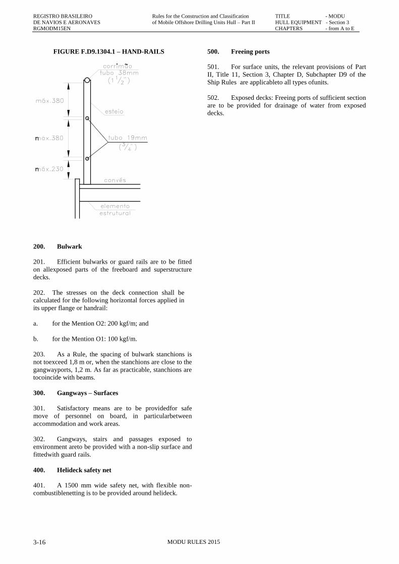
102. The handrails will be built with a pipe at the
top, two rods in intermediate lines below, brackets
spaced not exceeding three frames apart and an overall
height of about 1.05 m.
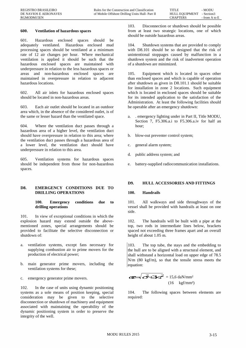
103. The top tube, the stays and the embedding to
the hull are to be aligned with a structural element, and
shall withstand a horizontal load on upper edge of 78.5
N/m (80 kgf/m), so that the tensile stress meets the
equation:
22 3 c = 15,6 daN/mm²
(16 kgf/mm²)
104. The following spaces between elements are
required:
REGISTRO BRASILEIRO Rules for the Construction and Classification TITLE - MODU
DE NAVIOS E AERONAVES of Mobile Offshore Drilling Units Hull – Part II HULL EQUIPMENT - Section 3 RGMODM15EN CHAPTERS - from A to E
MODU RULES 2015 3-16
FIGURE F.D9.1304.1 – HAND-RAILS
200. Bulwark
201. Efficient bulwarks or guard rails are to be fitted
on allexposed parts of the freeboard and superstructure
decks.
202. The stresses on the deck connection shall be
calculated for the following horizontal forces applied in
its upper flange or handrail:
a. for the Mention O2: 200 kgf/m; and
b. for the Mention O1: 100 kgf/m.
203. As a Rule, the spacing of bulwark stanchions is
not toexceed 1,8 m or, when the stanchions are close to the
gangwayports, 1,2 m. As far as practicable, stanchions are
tocoincide with beams.
300. Gangways – Surfaces
301. Satisfactory means are to be providedfor safe
move of personnel on board, in particularbetween
accommodation and work areas.
302. Gangways, stairs and passages exposed to
environment areto be provided with a non-slip surface and
fittedwith guard rails.
400. Helideck safety net
401. A 1500 mm wide safety net, with flexible non-
combustiblenetting is to be provided around helideck.
500. Freeing ports
501. For surface units, the relevant provisions of Part
II, Title 11, Section 3, Chapter D, Subchapter D9 of the
Ship Rules are applicableto all types ofunits.
502. Exposed decks: Freeing ports of sufficient section
are to be provided for drainage of water from exposed
decks.
REGISTRO BRASILEIRO Rules for the Construction and Classification TITLE - MODU
DE NAVIOS E AERONAVES of Mobile Offshore Drilling Units Hull- Part II HULL EQUIPMENT - Section3 RGMODM15EN CHAPTERS - from A to E
MODU RULES 2015 3-17
CHAPTER E
FIRE PROTECTION, FIRE DETECTION AND
FIRE EXTINCTION
CHAPTER CONTENTS
E1. GENERAL
E2. STRUCTURAL FIRE PROTECTION
E3. PROTECTION OF ACCOMMODATION
SPACES, SERVICE SPACES AND
CONTROL STATIONS
E4. MEANS OF ESCAPE
E5. FIRE SAFETY SYSTEMS
E6. EMERGENCY ESCAPE BREATHING
DEVICES
E7. FIRE PROTECTIN AND EXTINCTION
E8. FIRE PPMPS, FIRE MAINS, HYDRANTS
AND HOSES
E9. FIRE-EXTINGUISHING SYSTEMS
E10. PORTABLE FIRE EXTINGUISHERS IN
ACCOMMODATION, SERVICE AND
WORKING SPACES
E11. FIRE DETECTION AND ALARM SYSTEM
E12. FLAMMABLE GAS DETECTION AND
ALARM SYSTEM
E13. HYDROGEN SULPHIDE DETECTION AND
ALARM SYSTEM
E14. FIRE FIGHTERS OUTIFT
E15. RECHARGING OF AIR CYLINDERS
E16. ARRANGEMENTS IN MACHINERY AND
WORKING SPACES
E17. PROVISIONS FOR HELICOPTER
FACILITIES
E18. STORAGE OF GAS CYLINDERS
E19. FIRE CONTROL PLAN
E20. OPERATIONAL READINES AND
MAINTENANCE
E1. GENERAL
100. Application
200. Alternative design and arrangements
201. When fire safety design or arrangements
deviate from the prescriptive provisions of the Code,
alternative design and arrangements shall be carried out
in accordance with SOLAS regulation II-2/17.
E2. STRUCTURAL FIRE PROTECTION
100. Application
101. These provisions have been formulated
principally for units having their hull superstructure,
structural bulkheads, decks and deckhouses constructed
of steel.
102. Units constructed of other materials may be
accepted, provided that, in the opinion of the RBNA,
they provide an equivalent standard of safety.
103. Structural fire protection details, materials and
methods of construction shall be in accordance with the
FTP Code, as applicable, and SOLAS regulations II-
2/5.3 and II-2/6, as applied to cargo ships.
200. Fire integrity of bulkheads and decks
201. In addition to complying with the specific
provisions for fire integrity of bulkheads and decks in
this subchapter and in subchapterE3, the minimum fire
integrity of bulkheads and decks shall be as prescribed
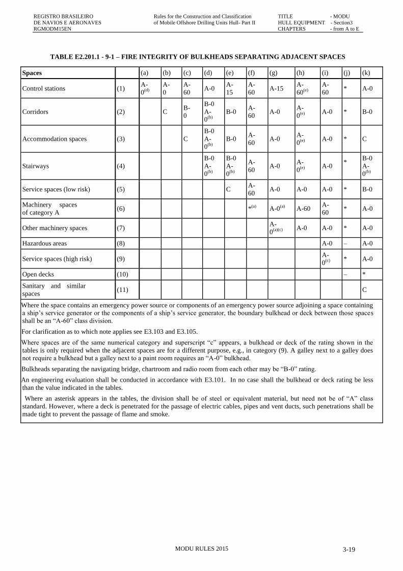
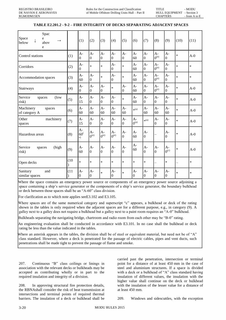
in tables T.E2.201.1 and T.E2.201.2.
202. Exterior boundaries of superstructures and
deckhouses enclosing accommodation, including any
overhanging decks which support such accommodation,
shall be constructed to “A-60” standard for the whole of
the portion which faces and is within 30 m of the centre
of the rotary table.
203. For units that have a movable substructure the
30 m shall be measured with the substructure at its
closest drilling position to the accommodation. The
RBNA may accept equivalent arrangements.
204. The following provisions shall govern
application of the tables:
205. Tables T.E2.201.1 and T.E2.201.2 shall apply
respectively to the bulkheads and decks separating
adjacent spaces.
206. For determining the appropriate fire integrity
standards to be applied to divisions between adjacent
spaces, such spaces are classified according to their fire
risk, as shown in categories (a) to (k) below. The title of
each category is intended to be typical rather than
REGISTRO BRASILEIRO Rules for the Construction and Classification TITLE - MODU
DE NAVIOS E AERONAVES of Mobile Offshore Drilling Units Hull – Part II HULL EQUIPMENT - Section 3 RGMODM15EN CHAPTERS - from A to E
MODU RULES 2015 3-18
restrictive. The letter preceding each category refers to
the applicable column or row in the tables:
a. Control stationsare spaces as defined in Part I,
Title MODU, Section 1, A2.114.
b. Corridors means corridors and lobbies.
c. Accommodation spaces are spaces as defined in
section 1.3, excluding corridors, lavatories and
pantries containing no cooking appliances.
d. Stairways are interior stairways, lifts and
escalators (other than those wholly contained
within the machinery spaces) and enclosures
thereto. In this connection a stairway which is
enclosed only at one level shall be regarded as part
of the space from which it is not separated by a fire
door.
e. Service spaces (low risk) are lockers, store-rooms
and working spaces in which flammable materials
are not stored, drying rooms and laundries.
f. Machinery spaces of category A are spaces as
defined in Part I, Title MODU, Section 1, A2.137.
g. Other machinery spaces are spaces as defined in
Part I, Title MODU, Section 1, A2.136 other than
machinery spaces of category A.
h. Hazardous areas are areas as defined in Part I,
Title MODU, Section 1, A2.129.
i. Service spaces (high risk) are lockers, store-rooms
and working spaces in which flammable materials
are stored, galleys, pantries containing cooking
appliances, paint rooms and workshops other than
those forming part of the machinery space.
j. Open decks are open deck spaces, excluding
hazardous areas.
k. Sanitary and similar spaces are communal
sanitary facilities such as showers, baths,
lavatories, etc., and isolated pantries containing no
cooking appliances. Sanitary facilities which serve
a space and with access only from that space shall
be considered a portionof the space in which they
are located.
REGISTRO BRASILEIRO Rules for the Construction and Classification TITLE - MODU
DE NAVIOS E AERONAVES of Mobile Offshore Drilling Units Hull- Part II HULL EQUIPMENT - Section3 RGMODM15EN CHAPTERS - from A to E
MODU RULES 2015 3-19
TABLE E2.201.1 - 9-1 – FIRE INTEGRITY OF BULKHEADS SEPARATING ADJACENT SPACES
Spaces (a) (b) (c) (d) (e) (f) (g) (h) (i) (j) (k)
Control stations (1) A-
0(d)
A-
0
A-
60 A-0
A-
15
A-
60 A-15
A-
60(e)
A-
60 * A-0
Corridors (2) C B-
0
B-0
A-
0(b)
B-0 A-
60 A-0
A-
0(e)
A-0 * B-0
Accommodation spaces (3) C
B-0
A-
0(b)
B-0 A-
60 A-0
A-
0(e)
A-0 * C
Stairways (4)
B-0
A-
0(b)
B-0
A-
0(b)
A-
60 A-0
A-
0(e)
A-0
*
B-0
A-
0(b)
Service spaces (low risk) (5) C A-
60 A-0 A-0 A-0 * B-0
Machinery spaces
of category A (6) *
(a) A-0
(a) A-60
A-
60 * A-0
Other machinery spaces (7) A-
0(a)(c)
A-0 A-0 * A-0
Hazardous areas (8) A-0 – A-0
Service spaces (high risk) (9) A-
0(c)
* A-0
Open decks (10) – *
Sanitary and similar
spaces (11) C
(a) Where the space contains an emergency power source or components of an emergency power source adjoining a space containing
a ship‟s service generator or the components of a ship‟s service generator, the boundary bulkhead or deck between those spaces
shall be an “A-60” class division.
(b) For clarification as to which note applies see E3.103 and E3.105.
(c) Where spaces are of the same numerical category and superscript “c” appears, a bulkhead or deck of the rating shown in the
tables is only required when the adjacent spaces are for a different purpose, e.g., in category (9). A galley next to a galley does
not require a bulkhead but a galley next to a paint room requires an “A-0” bulkhead.
(d) Bulkheads separating the navigating bridge, chartroom and radio room from each other may be “B-0” rating.
(e) An engineering evaluation shall be conducted in accordance with E3.101. In no case shall the bulkhead or deck rating be less
than the value indicated in the tables.
* Where an asterisk appears in the tables, the division shall be of steel or equivalent material, but need not be of “A” class
standard. However, where a deck is penetrated for the passage of electric cables, pipes and vent ducts, such penetrations shall be
made tight to prevent the passage of flame and smoke.
REGISTRO BRASILEIRO Rules for the Construction and Classification TITLE - MODU
DE NAVIOS E AERONAVES of Mobile Offshore Drilling Units Hull – Part II HULL EQUIPMENT - Section 3 RGMODM15EN CHAPTERS - from A to E
MODU RULES 2015 3-20
TABLE E2.201.2 - 9-2 – FIRE INTEGRITY OF DECKS SEPARATING ADJACENT SPACES
Space
below ↓
Spac
e
abov
e
→ (1) (2) (3) (4) (5) (6) (7) (8) (9) (10) (11)
Control stations (1) A-
0
A-
0
A-
0
A-
0
A-
0
A-
60
A-
0
A-
0(e)
A-
0 * A-0
Corridors (2) A-
0 * *
A-
0 *
A-
60
A-
0
A-
0(e)
A-
0 * *
Accommodation spaces (3) A-
60
A-
0 *
A-
0 *
A-
60
A-
0
A-
0(e)
A-
0 * *
Stairways (4) A-
0
A-
0
A-
0 *
A-
0
A-
60
A-
0
A-
0(e)
A-
0 * A-0
Service spaces (low
risk) (5)
A-
15
A-
0
A-
0
A-
0 *
A-
60
A-
0
A-
0
A-
0 * A-0
Machinery spaces
of category A (6)
A-
60
A-
60
A-
60
A-
60
A-
60 *
(a)
A-
60
A-
60
A-
60 * A-0
Other machinery
spaces (7)
A-
15
A-
0
A-
0
A-
0
A-
0
A-
0(a)
*
(a)
A-
0
A-
0 * A-0
Hazardous areas (8)
A-
60(
e)
A-
0(e)
A-
0(e)
A-
0(e)
A-
0
A-
60
A-
0 –
A-
0 * A-0
Service spaces (high
risk) (9)
A-
60
A-
0
A-
0
A-
0
A-
0
A-
60
A-
0
A-
0
A-
0(c)
* A-0
Open decks (10
) * * * * * * * – * – *
Sanitary and
similar spaces
(11
)
A-
0
A-
0 *
A-
0 *
A-
0
A-
0
A-
0
A-
0 * *
(a) Where the space contains an emergency power source or components of an emergency power source adjoining a
space containing a ship‟s service generator or the components of a ship‟s service generator, the boundary bulkhead
or deck between those spaces shall be an “A-60” class division.
(b) For clarification as to which note applies seeE3.102 and E3.105.
(c) Where spaces are of the same numerical category and superscript “c” appears, a bulkhead or deck of the rating
shown in the tables is only required when the adjacent spaces are for a different purpose, e.g., in category (9). A
galley next to a galley does not require a bulkhead but a galley next to a paint room requires an “A-0” bulkhead.
(d) Bulkheads separating the navigating bridge, chartroom and radio room from each other may be “B-0” rating.
(e) An engineering evaluation shall be conducted in accordance with E3.101. In no case shall the bulkhead or deck
rating be less than the value indicated in the tables.
* Where an asterisk appears in the tables, the division shall be of steel or equivalent material, but need not be of “A”
class standard. However, where a deck is penetrated for the passage of electric cables, pipes and vent ducts, such
penetrations shall be made tight to prevent the passage of flame and smoke.
207. Continuous “B” class ceilings or linings in
association with the relevant decks or bulkheads may be
accepted as contributing wholly or in part to the
required insulation and integrity of a division.
208. In approving structural fire protection details,
the RBNAshall consider the risk of heat transmission at
intersections and terminal points of required thermal
barriers. The insulation of a deck or bulkhead shall be
carried past the penetration, intersection or terminal
point for a distance of at least 450 mm in the case of
steel and aluminium structures. If a space is divided
with a deck or a bulkhead of “A” class standard having
insulation of different values, the insulation with the
higher value shall continue on the deck or bulkhead
with the insulation of the lesser value for a distance of
at least 450 mm.
209. Windows and sidescuttles, with the exception
REGISTRO BRASILEIRO Rules for the Construction and Classification TITLE - MODU
DE NAVIOS E AERONAVES of Mobile Offshore Drilling Units Hull- Part II HULL EQUIPMENT - Section3 RGMODM15EN CHAPTERS - from A to E
MODU RULES 2015 3-21
of navigating bridge windows, shall be of the non-
opening type. Navigating bridge windows may be of the
opening type provided the design of such windows
permits rapid closure. The RBNA may permit windows
and sidescuttles outside hazardous areas to be of the
opening type.
210. The fire resistance of doors shall, as far as
practicable, be equivalent to that of the division in
which they are fitted. External doors in superstructures
and deckhouses shall be constructed to at least “A-0”
class standard and be self-closing, where practicable.
211. Self-closing doors in fire rated bulkheads shall
not be fitted with hold-back hooks. However, hold-back
arrangements incorporating remote release fittings of
the fail-safe type may be utilized.
E3. PROTECTION OF ACCOMMODATION
SPACES, SERVICE SPACES AND
CONTROL STATIONS
100. Protection of accommodation spaces, service
spaces and control stations
101. In general, accommodation spaces, service
spaces and control stations shall not be located adjacent
to hazardous areas. However, where this is not
practicable, an engineering evaluation shall be
performed to ensure that the level of fire protection and
blast resistance of the bulkheads and decks separating
these spaces from the hazardous areas are adequate for
the likely hazard.
Guidance
An A-class bulkhead may be capable of withstanding a
blast pressure of about 0,01 N/mm2 (0,1 bar).
Typical explosion pressures expected from the ignition
of hydrocarbon vapours during a blowout approach the
range of 0,02 to 0,04 N/mm2 (0,2-0,4 bar).
Thus, without further means of blast protection,
personnel cannot be effectively shielded from a drill
floor expolsion by A-class bulkheads.
(Source: US Coastguard 2011 Report of the
Investigation into the Explosion,Fire and Sinking
aboard the Moblie Offshore Drilling Unit
DEEPWATER HORIZON on April 20, 2010).
End of guidance
102. All bulkheads that are to be “A” class divisions
shall extend from deck to deck and to the deckhouse
side or other boundaries.
103. All bulkheads forming “B” class divisions
shall extend from deck to deck and to the deckhouse
side or other boundaries, unless continuous “B” class
ceilings or linings are fitted on both sides of the
bulkhead, in which case the bulkhead may terminate at
the continuous ceiling or lining. In corridor bulkheads,
ventilation openings may be permitted only in and
under the doors of cabins, public spaces, offices and
sanitary spaces. The openings shall be provided only in
the lower half of the door. Where such an opening is in
or under a door, the total net area of any such opening
or openings shall not exceed 0.05 m2. When such an
opening is cut in a door it shall be fitted with a grille
made of non-combustible material. Such openings shall
not be provided in a door in a division forming a
stairway enclosure.
104. Stairs shall be constructed of steel or
equivalent material.
105. Stairways which penetrate only a single deck
shall be protected at least at one level by “A” or “B”
class divisions and self-closing doors so as to limit the
rapid spread of fire from one deck to another. Personnel
lift trunks shall be protected by “A” class divisions.
Stairways and lift trunks which penetrate more than a
single deck shall be surrounded by “A” class divisions
and protected by self-closing doors at all levels.
106. Air spaces enclosed behind ceilings, panellings
or linings shall be divided by close fitting draught stops
spaced not more than 14 m apart. In the vertical
direction, such enclosed air spaces, including those
behind linings of stairways, trunks, etc., shall be closed
at each deck.
107. Except for insulation in refrigerated
compartments, insulation material, pipe and vent duct
lagging, ceilings, linings and bulkheads shall be of non-
combustible material. Insulation of pipe fittings for cold
service systems and vapour barriers and adhesives used
in conjunction with insulation need not be non-
combustible but they shall be kept to a minimum and
their exposed surfaces shall have low-flame spread
characteristics *. In spaces where penetration of oil
products is possible, the surfaces of the insulation shall
be impervious to oil or oil vapours.
* Refer to Recommendation on improved fire test
procedures for surface flammability of bulkhead,
ceiling and deck finish materials, adopted by the
Organization by resolution A.653(16), in conjunction
with Guidelines on the evaluation of fire hazard
properties of materials, adopted by the Organization by
resolution A.166(ES.IV) and Annex 1, Part 1 of the
International Code for Application of Fire Test
Procedures (FTP Code).
108. The framing, including grounds and the joint
pieces of bulkheads, linings, ceilings and draught stops,
shall be of non-combustible material.
109. All exposed surfaces in corridors and stairway
enclosures and surfaces in concealed or inaccessible
spaces in accommodation and service spaces and
control stations shall have low-flame spread
characteristics. Exposed surfaces of ceilings in
REGISTRO BRASILEIRO Rules for the Construction and Classification TITLE - MODU
DE NAVIOS E AERONAVES of Mobile Offshore Drilling Units Hull – Part II HULL EQUIPMENT - Section 3 RGMODM15EN CHAPTERS - from A to E
MODU RULES 2015 3-22
accommodation and service spaces and control stations
shall have low-flame spread characteristics.
110. Bulkheads, linings and ceilings may have
combustible veneers provided that the thickness of such
veneers shall not exceed 2.5 mm within any space other
than corridors, stairway enclosures and control stations
where the thickness shall not exceed 1.5 mm.
Combustible materials used on these surfaces shall have
a calorific value * not exceeding 45 mJ/m2 of the area
for the thickness used.
* Refer to the recommendations published by the
International Organization for Standardization, in
particular publication ISO 1716:2002, Reaction to fire
tests for building products – Determination of the heat
of combustion.
111. Primary deck coverings, if applied within
accommodation and service spaces and control stations,
shall be of approved material which will not readily
ignite, this being determined in accordance with the
FTP Code.
112. Paints, varnishes and other finishes used on
exposed interior surfaces shall not be capable of
producing excessive quantities of smoke and toxic
products, this being determined in accordance with the
FTP Code.
113. Ventilation ducts shall be of non-combustible
material. Short ducts, however, not generally exceeding
2 m in length and with a cross-sectional area not
exceeding 0.02 m2 need not be non-combustible,
subject to the following conditions:
a. these ducts shall be of a material which, in the
opinion of the RBNA, has a low fire risk;
b. they may only be used at the end of the ventilation
device;
c. they shall not be situated less than 600 mm,
measured along the duct, from where it penetrates
any “A” or “B” class division including continuous
“B” class ceilings.
114. Where a thin plated duct with a free cross-
sectional area equal to, or less than, 0.02 m2 passes
through “A” class bulkhead or decks, the opening shall
be lined with a steel sheet sleeve having a thickness of
at least 3 mm and a length of at least 200 mm, divided
preferably into 100 mm on each side of the bulkhead or,
in the case of the deck, wholly laid on the lower side of
the deck pierced. Where ventilation ducts with a cross-
sectional area exceeding 0.02 m2 pass through class “A”
bulkheads or decks, the opening shall be lined with a
steel sheet sleeve unless the ducts passing through the
bulkheads or decks are of steel in the vicinity of
penetrations through the deck or bulkhead; the ducts
and sleeves at such places shall comply with the
following:
a. The ducts or sleeves shall have a thickness of at
least 3 mm and a length of at least 900 mm. When
passing through bulkheads, this length shall be
divided preferably into 450 mm on each side of the
bulkhead. These ducts, or sleeves lining such ducts,
shall be provided with fire insulation. The
insulation shall have at least the same fire integrity
as the bulkhead or deck through which the duct
passes. Equivalent penetration protection may be
provided to the satisfaction of the RBNA.
b. Ducts with a cross-sectional area exceeding
0.075 m2, except those serving hazardous areas,
shall be fitted with fire dampers in addition to
meeting the provisions of E3.114.a1. The fire
damper shall operate automatically but shall also
be capable of being closed manually from both
sides of the bulkhead or deck.The damper shall be
provided with an indicator which shows whether
the damper is open or closed. Fire dampers are not
required, however, where ducts pass through
spaces surrounded by “A” class divisions, without
serving those spaces, provided those ducts have the
same fire integrity as the divisions which they
pierce. The RBNA may, given special
considerations, permit operation from one side of a
division only.
115. In general, ventilation systems for machinery
spaces of category A, galleys and hazardous areas shall
be separated from each other and from the ventilation
systems serving other spaces. Ducts serving hazardous
areas shall not pass through accommodation spaces,
service spaces, or control spaces. Ducts provided for the
ventilation of machinery spaces of category A and
galleys shall not pass through accommodation spaces,
control stations or service spaces unless:
a. the ducts are constructed of steel having a thickness
of at least 3 mm and 5 mm for ducts the widths or
diameters of which are up to and including 300 mm
and 760 mm and over respectively and, in the case
of such ducts, the widths or diameters of which are
between 300 mm and 760 mm, having a thickness
obtained by interpolation;
b. the ducts are suitably supported and stiffened;
c. the ducts are fitted with automatic fire dampers
close to the boundaries penetrated; and
d. the ducts are insulated to “A-60” class standard
from the machinery spaces or galleys to a point at
least 5 m beyond each fire damper;
e. or
f. the ducts are constructed of steel in accordance
with E3.115.a and E3.115.b2; and
g. the ducts are insulated to “A-60” class standard
throughout the accommodation spaces, service
spaces or control stations.
REGISTRO BRASILEIRO Rules for the Construction and Classification TITLE - MODU
DE NAVIOS E AERONAVES of Mobile Offshore Drilling Units Hull- Part II HULL EQUIPMENT - Section3 RGMODM15EN CHAPTERS - from A to E
MODU RULES 2015 3-23
116. Ducts provided for the ventilation of
accommodation spaces, service spaces or control
stations shall not pass through machinery spaces of
category A, galleys or hazardous areas. However, the
RBNA may permit a relaxation from these provisions,
except for the ducts passing through hazardous areas,
provided that:
a. the ducts where they pass through a machinery
space of category A or a galley are constructed of
steel in accordance with E3.115.a and E3.115.b;
b. automatic fire dampers are fitted close to the
boundaries penetrated; and
c. the integrity of the machinery space or galley
boundaries is maintained at the penetrations;
or
d. the ducts where they pass through a machinery
space of category A or a galley are constructed of
steel in accordance with paragraphs E3.115.a
and E3.115.b; and
e. are insulated to “A-60” standard within the
machinery space or galley.
117. Ventilation ducts with a cross-sectional area
exceeding 0.02 m2 passing through “B” class bulkheads
shall be lined with steel sheet sleeves of 900 mm in
length divided preferably into 450 mm on each side of
the bulkhead unless the duct is of steel for this length.
118. Where they pass through accommodation
spaces or spaces containing combustible materials, the
exhaust ducts from galley ranges shall be of equivalent
fire integrity to “A” class divisions.
119. Each galley exhaust duct shall be fitted with:
a. a grease trap readily removable for cleaning;
b. a fire damper located in the galley end of the duct
which is automatically and remotely operated and,
in addition a remotely operated fire damper located
in the exhaust end of the duct;
c. arrangements, operable from within the galley, for
shutting off the exhaust fans; and
d. fixed means for extinguishing a fire within the
duct.
120. The main inlets and outlets of all ventilation
systems shall be capable of being closed from outside
the spaces being ventilated.
121. spaces, control stations, machinery spaces and
hazardous areas shall be capable of being stopped from
an easily accessible position outside the space being
served. The accessibility of this position in the event of
a fire in the spaces served shall be specially considered.
The means provided for stopping the power ventilation
serving machinery spaces or hazardous areas shall be
entirely separate from the means provided for stopping
ventilation of other spaces.
122. Windows and sidescuttles in boundaries which
are required to meet an “A-60” standard which face the
drill floor area shall be:
a. constructed to an “A-60” standard; or
b. protected by a water curtain; or
c. fitted with shutters of steel or equivalent material.
123. The ventilation of the accommodation spaces
and control stations shall be arranged in such a way as
to prevent the ingress of flammable, toxic or noxious
gases or smoke from surrounding areas.
E4. MEANS OF ESCAPE
100. Means of escape
101. Within the accommodation spaces, service
spaces and control stations the following provisions
shall be applied:
a. In every general area which is likely to be regularly
manned or in which personnel are accommodated
at least two separate escape routes shall be
provided, situated as far apart as practicable, to
allow ready means of escape to the open decks and
embarkation stations. Exceptionally, the RBNA in
agreement with the RBNA may permit only one
means of escape, due regard being paid to the
nature and location of spaces and to the number of
persons who might normally be accommodated or
employed there.
b. Stairways shall normally be used for means of
vertical escape; however, a vertical ladder may be
used for one of the means of escape when the
installation of a stairway is shown to be
impracticable.
c. Every escape route shall be readily accessible and
unobstructed and all exit doors along the route shall
be readily operable. Dead-end corridors exceeding
7 m in length shall not be permitted.
d. In addition to the emergency lighting, the means of
escape in accommodation areas, including
stairways and exits, shall be marked by lighting or
photoluminescent strip indicators placed not more
than 300 mm above the deck at all points of the
escape route, including angles and intersections.
The marking shall enable personnel to identify the
routes of escape and readily identify the escape
exits. If electric illumination is used, it shall be
supplied by the emergency source of power and it
shall be so arranged that the failure of any single
REGISTRO BRASILEIRO Rules for the Construction and Classification TITLE - MODU
DE NAVIOS E AERONAVES of Mobile Offshore Drilling Units Hull – Part II HULL EQUIPMENT - Section 3 RGMODM15EN CHAPTERS - from A to E
MODU RULES 2015 3-24
light or cut in a lighting strip will not result in the
marking being ineffective. Additionally, escape
route signs and fire equipment location markings
shall be of photoluminescent material or marked by
lighting. The RBNAshall ensure that such lighting
or photoluminescent equipment has been evaluated,
tested and applied in accordance with the FSS
Code.
102. Two means of escape shall be provided from
each machinery space of category A. Ladders shall be
of steel or other equivalent material. In particular, one
of the following provisions shall be complied with:
a. two sets of ladders, as widely separated as possible,
leading to doors in the upper part of the space,
similarly separated and from which access is
provided to the open deck. One of these ladders
shall be located within a protected enclosure that
satisfies T.E2.201.1 and T.E2.201.2, category (4),
from the lower part of the space it serves to a safe
position outside the space. Self-closing fire doors
of the same fire integrity standards shall be fitted in
the enclosure. The ladder shall be fixed in such a
way that heat is not transferred into the enclosure
through non-insulated fixing points. The enclosure
shall have minimum internal dimensions of at
least 800 mm by 800 mm, and shall have
emergency lighting provisions; or
b. one ladder leading to a door in the upper part of the
space from which access is provided to the open
deck. Additionally, in the lower part of the space,
in a position well separated from the ladder
referred to, a steel door capable of being operated
from each side shall be provided with access to a
safe escape route from the lower part of the space
to the open deck.
103. From machinery spaces other than those of
category A, escape routes shall be provided to the
satisfaction of the RBNA having regard to the nature
and location of the space and whether persons are
normally employed there.
104. Lifts shall not be considered as forming one of
the required means of escape.
105. Consideration shall be given by the RBNA to
the siting of superstructures and deckhouses such that in
the event of fire at the drill floor at least one escape
route to the embarkation position and survival craft is
protected against radiation effects of that fire as far as
practicable.
106. Stairways and corridors used as a means of
escape shall meet the provisions of paragraph 13.3 of
the FSS Code.
E5. FIRE SAFETY SYSTEMS
Note:
Fire safety systems shall be in accordance with the FSS
Code, as applicable.
E6. EMERGENCY ESCAPE BREATHING
DEVICES
100. EEBD
101. Emergency escape breathing devices (EEBDs)
shall comply with the FSS Code. Spare emergency
escape breathing devices shall be kept on board to the
satisfaction of the RBNA.
102. Emergency escape breathing devices shall be
provided as follows:
a. In machinery spaces of category A containing
internal combustion machinery used for main
propulsion, EEBDs shall be positioned as follows:
i. one (1) EEBD in the engine control room,
if located within the machinery space;
ii. one (1) EEBD in workshop areas. If there
is, however, a direct access to an escape
way from the workshop, an EEBD is not
required; and
iii. one (1) EEBD on each deck or platform
level near the escape ladder constituting
the second means of escape from the
machinery space (the other means being
an enclosed escape trunk or watertight
door at the lower level of the space).
iv. Alternatively, a different number or
location may be determined by the RBNA
taking into consideration the layout and
dimensions or the normal manning of the
space.
b. For machinery spaces of category A other than
those containing internal combustion machinery
used for main propulsion, one (1) EEBD shall, as
a minimum, be provided on each deck or platform
level near the escape ladder constituting the
second means of escape from the space (the other
means being an enclosed escape trunk or
watertight door at the lower level of the space).
c. For other machinery spaces, the number and
location of EEBDs are to be determined by the
RBNA.
REGISTRO BRASILEIRO Rules for the Construction and Classification TITLE - MODU
DE NAVIOS E AERONAVES of Mobile Offshore Drilling Units Hull- Part II HULL EQUIPMENT - Section3 RGMODM15EN CHAPTERS - from A to E
MODU RULES 2015 3-25
E7. FIRE PROTECTIN AND EXTINCTION
100. Fire plan contents
101. Fire protection arrangements and fire
extinguishing systems are to be in accordance with
theRules as specified herein. Fire control plans are to be
submitted for review on which thefollowing, as a
minimum, should be clearly shown:
a. Locations of fire control stations;
b. Various fire sections enclosed by various classes of
fire divisions;
c. Arrangement of fire detectors and manual fire alarm
stations;
d. Arrangement of combustible gas detectors;
e. Arrangement of hydrogen sulphide gas detectors;
f. Locations of respiratory protection equipment for
hydrogen sulphide;
g. General alarm actuating positions;
h. Arrangement of various fire-extinguishing appliances;
i. Locations of Fighter‟s Outfits;
j. Location of Helicopter Crash Kit;
k. Arrangement of water spray nozzles and sprinklers (if
fitted);
l. Locations of emergency shutdown (such as oil fuel
source shutdown, engine shutdown,
m. etc.) stations;
n. The Ventilating system including Fire dampers
positions, Ventilating Fans control
o. positions with indication of identification numbers of
Ventilating Fans serving each
p. section;
q. Arrangement of fire/watertight doors and their remote
control positions;
r. Blowout preventer control positions;
s. Escape route and means of access to different
compartments, decks, etc.;
t. Locations of Emergency Escape Breathing Devices
(EEBD); and
u. Arrangement of emergency muster stations and
life-saving appliances
E8. FIRE PUMPS, FIRE MAINS,
HYDRANTS AND HOSES
100. Water fire fighting system
101. Fire pumps
a. At least two independently driven power pumps
shall be provided, each arranged to draw directly
from the sea and discharge into a fixed fire main.
However, in units with high suction lifts, booster
pumps and storage tanks may be installed, provided
such arrangements will satisfy all the provisions of
E7.101 to E7.109.
b. At least one of the required pumps shall be
dedicated for fire-fighting duties and be available
for such duties at all times.
c. The arrangements of the pumps, sea suctions and
sources of power shall be such as to ensure that a
fire in any one space would not put both the
required pumps out of action.
d. The capacity of the required pumps shall be
appropriate to the fire-fighting services supplied
from the fire main. Where more pumps than
required are installed, their capacity shall be to the
satisfaction of the RBNA.
e. Each pump shall be capable of delivering at least
one jet simultaneously from each of any two fire
hydrants, hoses and 19 mm nozzles while
maintaining a minimum pressure of 0.35 N/mm2 at
any hydrant. In addition, where a foam system is
provided for protection of the helicopter deck, the
pump shall be capable of maintaining a pressure of
0.7 N/mm2 at the foam installation. If the water
consumption for any other fire protection or fire-
fighting purpose shall exceed the rate of the
helicopter deck foam installation, this consumption
shall be the determining factor in calculating the
required capacity of the fire pumps.
f. Where either of the required pumps is located in a
space not normally manned and, in the opinion of
the RBNA, is relatively far removed from working
areas, suitable provision shall be made for remote
start-up of that pump and remote operation of
associated suction and discharge valves.
g. Except as provided E7.102, sanitary, ballast, bilge
or general service pumps may be accepted as fire
pumps, provided that they are not normally used
for pumping oil.
h. Every centrifugal pump which is connected to the
fire main shall be fitted with a non-return valve.
i. Relief valves shall be provided in conjunction with
all pumps connected to the fire main if the pumps
are capable of developing a pressure exceeding the
design pressure of the fire main, hydrants and
REGISTRO BRASILEIRO Rules for the Construction and Classification TITLE - MODU
DE NAVIOS E AERONAVES of Mobile Offshore Drilling Units Hull – Part II HULL EQUIPMENT - Section 3 RGMODM15EN CHAPTERS - from A to E
MODU RULES 2015 3-26
hoses. Such valves shall be so placed and adjusted
as to prevent excessive pressure in the fire main
system.
102. Fixed fire main
a. A fixed fire main shall be provided and be so
equipped and arranged as per the present
Subchapter E8.
b. The diameter of the fire main and water service
pipes shall be sufficient for the effective
distribution of the maximum required discharge
from the required fire pumps operating
simultaneously.
c. With the required fire pumps operating
simultaneously, the pressure maintained in the fire
mains shall be to the satisfaction of the RBNA and
be adequate for the safe and efficient operation of
all equipment supplied therefrom.
d. The fire main shall, where practicable, be routed
clear of hazardous areas and be arranged in such a
manner as to make maximum use of any thermal
shielding or physical protection afforded by the
structure of the unit.
e. The fire main shall be provided with isolating
valves located so as to permit optimum utilization
in the event of physical damage to any part of the
main.
f. The fire main shall not have connections other than
those necessary for fire-fighting purposes.
g. All practical precautions consistent with having
water readily available shall be taken to protect the
fire main against freezing.
h. Materials readily rendered ineffective by heat shall
not be used for fire mains and hydrants unless
adequately protected. The pipes and hydrants shall
be so placed that the fire hoses may be easily
coupled to them.
i. A cock or valve shall be fitted to serve each fire
hose so that any fire hose may be removed while
the fire pumps are operating.
103. Fire hoses, nozzles & hydrants
a. The number and position of the hydrants shall be
such that at least two jets of water, not emanating
from the same hydrant, one of which shall be from
a single length of fire hose, may reach any part of
the unit normally accessible to those on board
while the unit is being navigated or is engaged in
drilling operations. A hose shall be provided for
every hydrant.
b. Fire hoses shall be of material approved by the
RBNA and be sufficient in length to project a jet of
water to any of the spaces in which they may be
required to be used. Their maximum length shall be
to the satisfaction of the RBNA. Every fire hose
shall be provided with a dual-purpose nozzle and
the necessary couplings. Fire hoses, together with
any necessary fittings and tools, shall be ready for
use at any time and shall be kept in conspicuous
positions near the water service hydrants or
connections.
c. Fire hoses shall have a length of at least 10 m, but
not more than:
i. 15 m in machinery spaces;
ii. 20 m in other spaces and open decks; and
iii. 25 m for open decks with a maximum breadth
in excess of 30 m.
d. Nozzles shall comply with the following:
i. Standard nozzle sizes shall be 12 mm, 16 mm
and 19 mm or as near thereto as possible.
Larger diameter nozzles may be permitted at
the discretion of the RBNA.
ii. For accommodation and service spaces, a
nozzle size greater than 12 mm need not be
used.
iii. For machinery spaces and exterior locations,
the nozzle size shall be such as to obtain the
maximum discharge possible from two jets at
the pressure specified in E7.105 from the
smallest pump, provided that a nozzle size
greater than 19 mm need not be used.
104. International shore connection: The surface
unit shall be provided with at least one international
shore connection complying with SOLAS regulation II-
2/10-2.1.7 and the FSS Code. Facilities shall be
available enabling such a connection to be used on any
side of the unit.
105. Water supply
a. At least two water supply sources (sea chests, valves,
strainers and pipes) are to be provided and so arranged
that one supply source failure will not put all supply
sources out of action.
b. For the self-elevating units, the following additional
fire water supply measures are to be provided:
i. Water is to be supplied from sea water main filled
by at least two submersible pumping systems.
One system failure will not put the other
system(s) out of function, and
ii. Water is to be supplied from drill water system
while unit lifting or lowering. Water storedin the
drill water tank(s) is not less than 40 m3 plus
REGISTRO BRASILEIRO Rules for the Construction and Classification TITLE - MODU
DE NAVIOS E AERONAVES of Mobile Offshore Drilling Units Hull- Part II HULL EQUIPMENT - Section3 RGMODM15EN CHAPTERS - from A to E
MODU RULES 2015 3-27
engine cooling water consumptions before unit
lifting or lowering. Alternatively, water may be
supplied from buffer tank(s) in which sea water
stored is not less the quantity as the above
mentioned.
E9. FIRE-EXTINGUISHING SYSTEMS
100. Fire extinguishing arrangement in
machinery spaces and in spaces containing
fired processes
101. In spaces where main or auxiliary oil-fired
boilers and other fired processes of equivalent thermal
rating are situated, or in spaces containing oil fuel units
or settling tanks, the unit shall be provided with the
following:
102. One of the following fixed fire-extinguishing
systems complying with SOLAS regulation II-2/10.4:
a fixed pressure water-spraying system;
a fixed gas fire-extinguishing system;
a fixed high-expansion foam installation.
103. Where the machinery space and spaces
containing fired processes are not entirely separate, or if
fuel oil can drain from the latter spaces into the
machinery space, the combined machinery space and
fired process space shall be considered as one
compartment.
104. At least two approved portable foam
extinguishers or equivalent in each space containing a
fired process and each space in which a part of the oil
fuel installation is situated. In addition, at least one
extinguisher of the same description with a capacity of
9 l for each burner, whereby the total capacity of the
additional extinguisher or extinguishers need not
exceed 45 l for any one space.
105. A receptacle containing sand, sawdust
impregnated with soda, or other approved dry material
in such quantity as may be required by the RBNA. An
approved portable extinguisher may be provided as an
alternative.
106. Spaces containing internal combustion
machinery used either for main propulsion or for other
purposes, when such machinery has a total power
output of not less than 750 kW, shall be provided with
the following arrangements:
one of the fixed arrangements required by E8.102.a;
and
one approved foam-type extinguisher of not less than
45 l capacity or equivalent in every engine space and
one approved portable foam extinguisher for each
750 kW of engine power output or part thereof. The
total number of portable extinguishers so supplied shall
be not less than two and need not exceed six.
107. The RBNAshall give special consideration to
the fire-extinguishing arrangements to be provided in
spaces not fitted with fixed fire-extinguishing
installations containing steam turbines which are
separated from boiler rooms by watertight bulkheads.
108. Where, in the opinion of the RBNA, a fire
hazard exists in any machinery space for which no
specific provisions for fire-extinguishing appliances are
prescribed in E7.101 to E7.107, there shall be provided
in, or adjacent to, that space a number of approved
portable fire extinguishers or other means of fire
extinction to the satisfaction of the RBNA.
200. Fixed fire extinguishing systems on drilling
and areas
a. A fixed water spray system is to be provided to
protect drilling area. The minimum waterapplication
rate is not less than 20.4 l/min·m2, or
b. At least two dual-purpose (jet/spray) fire monitors are
to be installed to cover drillingand well test areas. The
minimum capacity of each monitor is not less than
100m3/h.
c. The monitors may be operated either remotely or
locally. Monitor arranged for localoperation shall be
sited on an accessible protected position.
300. Fixed fire extinguishing systems on mud
processing area
301. A suitable fixed foam system is to be provided.
302. The system is to be capable of deliveringfoam
solution at a rate of not less than 6.5 l/min·m2 (4.1
l/min·m2 for Aqueous Film FormingFoam or Film-
Forming Fluoroprotein Foam) for 15 minutes.
303. Alternatively, a gas fixed fireextinguishing
system may be used for enclosed mud processing spaces.
E10. PORTABLE FIRE EXTINGUISHERS IN
ACCOMMODATION, SERVICE AND
WORKING SPACES
100. Portable fire extinguishers
101. Except for the supplemental arrangements
provided in E9.102, portable fire extinguishers in
accommodation spaces, service spaces, control stations,
machinery spaces of category A, other machinery
spaces, cargo spaces, weather deck and other spaces
shall be provided in number and arrangement in
accordance with the guidance provided by the
Organization * to the satisfaction of the RBNA.
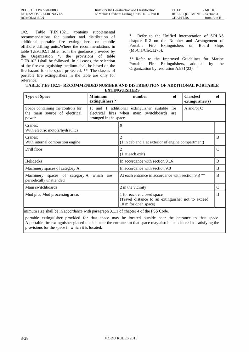
REGISTRO BRASILEIRO Rules for the Construction and Classification TITLE - MODU
DE NAVIOS E AERONAVES of Mobile Offshore Drilling Units Hull – Part II HULL EQUIPMENT - Section 3 RGMODM15EN CHAPTERS - from A to E
MODU RULES 2015 3-28
102. Table T.E9.102.1 contains supplemental
recommendations for number and distribution of
additional portable fire extinguishers on mobile
offshore drilling units.Where the recommendations in
table T.E9.102.1 differ from the guidance provided by
the Organization *, the provisions of table
T.E9.102.1shall be followed. In all cases, the selection
of the fire extinguishing medium shall be based on the
fire hazard for the space protected. ** The classes of
portable fire extinguishers in the table are only for
reference.
* Refer to the Unified Interpretation of SOLAS
chapter II-2 on the Number and Arrangement of
Portable Fire Extinguishers on Board Ships
(MSC.1/Circ.1275).
** Refer to the Improved Guidelines for Marine
Portable Fire Extinguishers, adopted by the
Organization by resolution A.951(23).
TABLE T.E9.102.1– RECOMMENDED NUMBER AND DISTRIBUTION OF ADDITIONAL PORTABLE
EXTINGUISHERS
Type of Space Minimum number of
extinguishers * Class(es) of
extinguisher(s)
Space containing the controls for
the main source of electrical
power
1; and 1 additional extinguisher suitable for
electrical fires when main switchboards are
arranged in the space
A and/or C
Cranes:
With electric motors/hydraulics
0
Cranes:
With internal combustion engine
2
(1 in cab and 1 at exterior of engine compartment)
B
Drill floor 2
(1 at each exit)
C
Helidecks In accordance with section 9.16 B
Machinery spaces of category A In accordance with section 9.8 B
Machinery spaces of category A which are
periodically unattended
At each entrance in accordance with section 9.8 ** B
Main switchboards 2 in the vicinity C
Mud pits, Mud processing areas 1 for each enclosed space
(Travel distance to an extinguisher not to exceed
10 m for open space)
B
* Minimum size shall be in accordance with paragraph 3.1.1 of chapter 4 of the FSS Code.
** A portable extinguisher provided for that space may be located outside near the entrance to that space.
A portable fire extinguisher placed outside near the entrance to that space may also be considered as satisfying the
provisions for the space in which it is located.
REGISTRO BRASILEIRO Rules for the Construction and Classification TITLE - MODU
DE NAVIOS E AERONAVES of Mobile Offshore Drilling Units Hull- Part II HULL EQUIPMENT - Section3
RGMODM15EN CHAPTERS - from A to E
MODU RULES 2015 3-29
E11. FIRE DETECTION AND ALARM
SYSTEM
100. General
101. Spaces having a fire risk shall be provided with
an automatic firedetection and alarm system.
102. In selecting the type of detectors, their following
features shall be taken intoaccount:
a. Capability to detect fire at the incipient stage;
b. Ability to avoid spurious alarm and trips; and
c. Suitability to the located environment.
103. The fire detection main indicator board is to be at
a manned control station and isto be clearly to indicate
where fire has been detected.
200. Machinery spaces
201. Fire detectors are to be fitted in normally
unattended machinery spaces.
202. Detection systems using only thermal detectors,
in general, are not to be permitted.
300. Accommodation and service spaces
301. An automatic fire detection and alarm system is
to be provided in all accommodation andservice spaces.
302. Accommodation space is to be fitted with smoke
detectors.
303. Thermal detectors are to be fitted in galleys.
400. Electrical rooms and control stations
401. Smoke detectors are to be provided in all
electrical rooms and control stations.
500. Drilling and mud processing areas
501. Flame or thermal detectors are to be installed in
open drilling and/or mud processing areas.
502. Smoke detectors may be used in enclosed mud
processing areas.
600. Manually operated alarm system
601. Sufficient manual fire alarm stations are to be
installed throughout the accommodationspaces, service
spaces and control stations.
602. One manually operated call point is to belocated
at each exit. Manually operated call points are to be
readily accessible in the corridorsof each deck such that no
part of the corridor is more than 20 m from a manually
operatedcall point.
603. Measures are to be taken to prevent inadvertent
operation of the manual call alarm system.
700. General alarms
701. A general alarm system is to be provided and so
installed as to be clearly perceptible inall parts of the unit.
Alarm signal devices are to be provided which will
produce adistinctive and strong note.
702. The signals used shall be limited to: general
emergency, toxic gas (hydrogen sulphide),combustible
gas, fire alarm and abandon unit signals.
703. The signals given over the general alarm system
shall be supplemented by instructionsover the public
address system.
704. At least in the following spaces general alarm is
to be capable of being operated:
a. Main control station;
b. Drilling console;
c. Navigating bridge (if any); and
d. Fire control station (if any).
800. Unnatended machinery spaces and remote
control
801. A fixed fire detection and fire alarm system
shall be installed in:
a. periodically unattended machinery spaces; and
b. machinery spaces where:
i. the installation of automatic and remote
control system and equipments has been
approved in lieu of continuous manning of the
spaces, and
ii. the main propulsion and associated machinery,
including the main sources of electrical power,
are provided with various degrees of automatic
or remote control and are under continuous
manned supervision from a control room.
900. Mud system level alarms
901. A suitable audible and visual alarm to indicate
significant increase or decrease in the level ofthe contents
of the mud pit is to be provided at the control station for
drilling operations and atthe mud pit. Equivalent means to
indicate possible abnormal conditions in the drilling
systemmay be considered by the RBNA.
REGISTRO BRASILEIRO Rules for the Construction and Classification TITLE - MODU
DE NAVIOS E AERONAVES of Mobile Offshore Drilling Units Hull – Part II HULL EQUIPMENT - Section 3
RGMODM15EN CHAPTERS - from A to E
MODU RULES 2015 3-30
E.12 FLAMMABLE GAS DETECTION AND
ALARM SYSTEM
100. Fixed automatic gas detection and alarm
system
101. A fixed automatic gas detection and alarm
system shall be provided to the satisfaction of the
RBNA so arranged as to monitor continuously all
enclosed areas of the unit in which an accumulation of
flammable gas may be expected to occur and capable of
indicating at the main control point by aural and visual
means the presence and location of an accumulation.
102. At least two portable gas monitoring devices
shall be provided, each capable of accurately measuring
a concentration of flammable gas.
200. Areas for protection
201. Fixed automatic combustible gas detection and
alarm systems are to be provided for thefollowing areas:
a. Cellar deck
b. Drill floor
c. Mud pit area
d. Shale shaker area
e. Enclosed spaces containing the open components of
mud circulation system from thebell nipple to the mud
pits.
f. Ventilation intakes of enclosed machinery spaces
contiguous to hazardous areas andcontaining internal
combustion engines and boilers;
g. Ventilation intakes and near other openings of
accommodation spaces.
300. Alarms
301. The gas detectors are to be connected to an
audible and visual alarm system with indicatorson the drill
floor and in the main control station. The alarm system is
to clearly indicate thelocation and concentration of the gas
hazard. The combustible gas detectors are to alarm atnot
more than 25% and at 60% of the lower explosive limit
(LEL).
400. Portable combustible gas detectors
401. In addition to the fixed automatic gas detection
system, two portable combustible gasdetectors are to be
provided on the unit.
E13. HYDROGEN SULPHIDE DETECTION
AND ALARM SYSTEM
100. Fixed automatic hydrogen sylphide gas
detection system
101. A fixed automatic hydrogen sulphide gas
detection and alarm system shall be provided to the
satisfaction of the RBNA so arranged as to monitor
continuously the drilling area, mud processing area and
well fluid test area of the unit and capable of giving
audible and visual alarm at the main control points. If
the alarm at the main control point is unanswered
within 2 min, the toxic gas (hydrogen sulphide) alarm
and the helideck status light shall be automatically
activated.
102. At least two portable hydrogen sulphide gas
monitoring devices shall be provided on the unit.
200. Areas for protection
201. A fixed automatic hydrogen sulphide gas
detection and alarm system are to be provided for
the following areas:
a. Drill area;
b. Mud processing area; and
c. Well test area.
300. Alarms
301. The detectors are to be connected to an audible
and visual alarm system with indicators inmain control
room. The system is clearly to indicate where gas has been
detected.
302. Low level alarm set at 10 ppm and high level
alarm set not higher than 300 ppm are to bedesigned. The
high level alarm is to activate an evacuation alarm.
303. If the alarm at the main control point is
unanswered within 2 min, the toxic gas
(hydrogensulphide) alarm and the helideck status light is
to be automatically activated.
400. Portable hydrogen sulphide gas detectors
401. At least two portable hydrogen sulphide gas
monitoring devices shall be provided on theunit.
500. Respiratory protection equipment for
hydrogen sulphide
501. A self-contained breathing apparatus (SCBA)
positive-pressure/pressure-demandbreathing equipment
with full-face piece and rated for a minimum of 30
minutes is to beprovided for each person in working areas
where hydrogen sulphide may be encountered,and each
person in other areas is to be provided with a SCBA rated
for a minimum of 15minutes, or
REGISTRO BRASILEIRO Rules for the Construction and Classification TITLE - MODU
DE NAVIOS E AERONAVES of Mobile Offshore Drilling Units Hull- Part II HULL EQUIPMENT - Section3
RGMODM15EN CHAPTERS - from A to E
MODU RULES 2015 3-31
502. A positive-pressure/pressure-demand air line
breathing equipment coupled with aSCBA equipped low
pressure warning alarm and rated for a minimum of 15
minutes is to beprovided for each person on board the unit.
503. Breathing air supply line stations are to be
provided at least in the following areas:
a. Living quarter;
b. Muster/evacuation area;
c. Drilling areas;
d. Mud processing areas;
e. Other working areas.
600. Alarms and public address:general alarms
601. A general alarm system is to be provided and so
installed as to be clearly perceptible inall parts of the unit.
Alarm signal devices are to be provided which will
produce adistinctive and strong note.
602. The signals used shall be limited to: general
emergency, toxic gas (hydrogen sulphide),combustible
gas, fire alarm and abandon unit signals.
603. The signals given over the general alarm system
shall be supplemented by instructionsover the public
address system.
604. At least in the following spaces general alarm is
to be capable of being operated:
a. Main control station;
b. Drilling console;
c. Navigating bridge (if any); and
d. Fire control station (if any).
700. Alarms and public address: mud system
level alarms
701. A suitable audible and visual alarm to indicate
significant increase or decrease in the level ofthe contents
of the mud pit is to be provided at the control station for
drilling operations and atthe mud pit. Equivalent means to
indicate possible abnormal conditions in the drilling
systemmay be considered by the RBNA.
800. Ventilation system alarm
See F2.300.
900. Public address
901. The public address system is to be a loudspeaker
installation enabling thebroadcast of messages into all
spaces where personnel are normally present and
musterstations.
902. It is to allow for the broadcast of messages from
navigation bridge, central controlroom, emergency
response centre, engine control room, ballast control
station, jackingcontrol station and drilling console.
903. It is to be installed with regard to acoustically
marginalconditions and not require any action from the
addressee. It is to be protected againstunauthorized use.
904. The minimum sound pressure levels for
broadcasting emergency announcementsare to be:
a. In interior spaces 75dB(A) and at least 20dB(A)
above the speech interference level;
b. In exterior spaces 80dB(A) and at least 15dB(A)
above the speech interference level.
E14. FIRE-FIGHTERS’ OUTFITS
100. Fire-fighters outfit
101. At least two fire-fighters‟ outfits complying
with the relevant requirements of the FSS Code shall be
provided, each with portable instruments for measuring
oxygen and flammable vapour concentrations
acceptable to the RBNA.
102. Two spare charges shall be provided for each
required breathing apparatus. Units that are equipped
with suitably located means for fully recharging the air
cylinders free from contamination need carry only one
spare charge for each required apparatus.
103. The fire-fighters‟ outfits shall be kept ready for
use in an easily accessible location that is permanently
and clearly marked. They shall be stored in two or more
widely separated locations.
E15. RECHARGING OF AIR CYLINDERS
100. Recharging of air cylinders
101. The apparatus for recharging air cylinders, if
provided, shall have its power supplied from the
emergency supply or be independently diesel-powered,
or be so constructed or equipped that the air cylinders
may be used immediately after recharging.
102. The apparatus shall be suitably located in a
sheltered space above main deck level on the unit.
REGISTRO BRASILEIRO Rules for the Construction and Classification TITLE - MODU
DE NAVIOS E AERONAVES of Mobile Offshore Drilling Units Hull – Part II HULL EQUIPMENT - Section 3
RGMODM15EN CHAPTERS - from A to E
MODU RULES 2015 3-32
103. Intakes for air compressors shall draw from a
source of clean air.
104. The air shall be filtered after compression to
eliminate compressor oil contamination.
105. The recharging capacity shall meet the
requirements of SOLAS regulation II-2/10.10.2.6.
106. The equipment and its installation shall be to
the satisfaction of the RBNA.
E16. ARRANGEMENTS IN MACHINERY
AND WORKING SPACES
100. Arrangements in machinery and working
spaces
101. Means shall be provided for stopping
ventilating fans serving machinery and working spaces
and for closing all doorways, ventilators, annular spaces
around funnels and other openings to such spaces.
These means shall be capable of being operated from
outside such spaces in case of fire.
102. Machinery driving forced and induced draught
fans, electric motor pressurization fans, oil fuel transfer
pumps, oil fuel unit pumps and other similar fuel pumps
shall be fitted with remote controls situated outside the
space concerned so that they may be stopped in the
event of a fire arising in the space in which they are
located.
103. Every oil fuel suction pipe from a storage,
settling or daily service tank situated above the double
bottom shall be fitted with a cock or valve capable of
being closed from outside the space concerned in the
event of a fire arising in the space in which such tanks
are situated. In the special case of deep tanks situated in
any shaft or pipe tunnel, valves on the tanks shall be
fitted but control in the event of fire may be effected by
means of an additional valve on the pipeline or lines
outside the tunnel or tunnels.
E17. PROVISIONS FOR HELICOPTER
FACILITIES
Note: reference is made to ths Ship Rule, Part II, Title
11, Section 3, Chapter E, Subchatper E.18.
100. Helicopter facilities
101. This section provides additional measures in
order to address the fire safety objectives for units fitted
with facilities for helicopters and meets the following
functional provisions:
a. helideck structure shall be adequate to protect the
unit from the fire hazards associated with
helicopter operations;
b. fire-fighting appliances shall be provided to
adequately protect the unit from the fire hazards
associated with helicopter operations;
c. refuelling facilities and operations shall provide the
necessary measures to protect the unit from the fire
hazards associated with helicopter operations; and
d. helicopter facility operation manuals, which may
be included in the operation manual and training
shall be provided.
102. The construction of the helidecks shall be of
steel or other equivalent materials. If the helideck forms
the deckhead of a deckhouse or superstructure, it shall
be insulated to “A-60” class standard. If the RBNA
permits aluminium or other low melting point metal
construction that is not made equivalent to steel, the
following provisions shall be satisfied:
a. ifthe helideck is cantilevered over the side of the
unit, after each fire that may have an effect on the
structural integrity of the helideck or its supporting
structures, the helideck shall undergo a structural
analysis to determine its suitability for further use;
and
b. if the helideck is located above the unit‟s
deckhouse or similar structure, the following
conditions shall be satisfied:
i. the deckhouse top and bulkheads under the
helideck shall have no openings;
ii. windows under the helideck shall be provided
with steel shutters; and
iii. after each fire on the helideck or supporting
structure the helideck shall undergo a
structural analysis to determine its suitability
for further use.
103. A helideck shall be provided with both a main
and an emergency means of escape and access for fire
fighting and rescue personnel. These shall be located as
far apart from each other as is practicable and
preferably on opposite sides of the helideck.
104. In close proximity to the helideck, the
following fire-fighting appliances shall be provided and
stored near the means of access to that helideck:
a. at least two dry powder extinguishers having a total
capacity of not less than 45 kg but not less than
9 kg each;
b. carbon dioxide extinguishers of a total capacity of
not less than 18 kg or equivalent;
c. a foam application system consisting of monitors
REGISTRO BRASILEIRO Rules for the Construction and Classification TITLE - MODU
DE NAVIOS E AERONAVES of Mobile Offshore Drilling Units Hull- Part II HULL EQUIPMENT - Section3
RGMODM15EN CHAPTERS - from A to E
MODU RULES 2015 3-33
or foam-making branch pipes capable of delivering
foam to all parts of the helideck in all weather
conditions in which the helideck is intended to be
available for helicopter operations. The minimum
capacity of the foam production system will
depend upon the size of the area to be protected,
the foam application rate, the discharge rates of
installed equipment and the expected duration of
application:
i. a minimum application rate of 6 l/m2 within a
circle having a diameter equal to the D-value;
ii. a minimum of 5 min discharge capability shall
be provided;
iii. foam delivery at the minimum application rate
shall start within 30 s of system activation;
d. the principal agent shall be suitable for use with
salt water and conform to performance standards
not inferior to those acceptable to the
Organization;
* Refer to the International Civil Aviation
Organization Airport Services Manual, part 1, Rescue
and Fire Fighting, chapter 8, Extinguishing Agent
Characteristics, paragraph 8.1.5, Foam Specifications
table 8-1, level „B‟.
e. at least two nozzles of an approved dual-purpose
type (jet/spray) and hoses sufficient to reach any
part of the helideck;
f. in addition to the provisions of section 9.13, two
fire-fighter‟s outfits; and
g. at least the following equipment shall be stored in
a manner that provides for immediate use and
protection from the elements:
i. adjustable wrench;
ii. blanket, fire-resistant;
iii. cutters, bolt, 600 mm;
iv. hook, grab or salving;
v. hacksaw, heavy duty complete with six spare
blades;
vi. ladder;
vii. lift line 5 mm diameter and 30 m in length;
viii. pliers, side-cutting;
ix. set of assorted screwdrivers;
x. harness knife complete with sheath; and
xi. crowbar.
105. Drainage facilities in way of helidecks shall
be:
a. constructed of steel or other arrangements
providing equivalent fire safety;
b. lead directly overboard independent of any other
system; and
c. designed so that drainage does not fall onto any
part of the unit.
106. Where the unit has helicopter refuelling, the
following provisions shall be complied with:
a. a designated area shall be provided for the storage
of fuel tanks which shall be:
i. as remote as is practicable from
accommodation spaces, escape routes and
embarkation stations; and
ii. . isolated from areas containing a source of
vapour ignition;
b. the fuel storage area shall be provided with
arrangements whereby fuel spillage may be
collected and drained to a safe location;
c. tanks and associated equipment shall be protected
against physical damage and from a fire in an
adjacent space or area;
d. where portable fuel storage tanks are used, special
attention shall be given to:
i. design of the tank for its intended purpose;
ii. mounting and securing arrangements;
iii. electric bonding; and
iv. inspection procedures;
e. storage tank fuel pumps shall be provided with
means which permit shutdown from a safe remote
location in the event of a fire. Where a
gravity-fuelling system is installed, equivalent
closing arrangements shall be provided to isolate
the fuel source;
f. the fuel pumping unit shall be connected to one
tank at a time. The piping between the tank and the
pumping unit shall be of steel or equivalent
material, as short as possible, and protected against
damage;
g. . electrical fuel pumping units and associated
control equipment shall be of a type suitable for the
location and potential hazards;
h. fuel pumping units shall incorporate a device
REGISTRO BRASILEIRO Rules for the Construction and Classification TITLE - MODU
DE NAVIOS E AERONAVES of Mobile Offshore Drilling Units Hull – Part II HULL EQUIPMENT - Section 3
RGMODM15EN CHAPTERS - from A to E
MODU RULES 2015 3-34
which will prevent over-pressurization of the
delivery or filling hose;
i. equipment used in refuelling operations shall be
electrically bonded; and
j. “NO SMOKING” signs shall be displayed at
appropriate locations.
E18. STORAGE OF GAS CYLINDERS
100. Gas cylinders
101. Where more than one cylinder of oxygen and
more than one cylinder of acetylene are carried
simultaneously, such cylinders shall be arranged in
accordance with the following:
a. . Permanent piping systems for oxyacetylene
systems are acceptable provided that they are
designed having due regard to standards and
codes of practice to the satisfaction of the
RBNA.
b. Where two or more cylinders of each gas are
intended to be carried in enclosed spaces,
separate dedicated storage rooms shall be
provided for each gas.
c. Storage rooms shall be constructed of steel,
and be well ventilated and accessible from the
open deck.
d. . Provision shall be made for the expeditious
removal of cylinders in the event of fire.
e. “NO SMOKING” signs shall be displayed at
the gas cylinder storage rooms.
f. Where cylinders are stowed in open locations
means shall be provided to:
i. protect cylinders and associated piping
from physical damage;
ii. minimize exposure to hydrocarbons; and
iii. ensure suitable drainage.
102. Fire-extinguishing arrangements for the
protection of areas or spaces where such cylinders are
stored shall be to the satisfaction of the RBNA.
E19. FIRE CONTROL PLAN
100. Fire control plan
101. A fire control plan complying with SOLAS
regulation II-2/15.2.4 shall be permanently exhibited.
E20. OPERATIONAL READINESS AND
MAINTENANCE
100. Functional provisions
101. The following functional provisions shall be
met:
a. gas detection systems, fire protection systems and
fire-fighting systems and appliances shall be
maintained ready for use; and
b. gas detection systems, fire protection systems and
fire-fighting systems and appliances shall be
properly tested and inspected.
102. At all times while the unit is in service, the
provisions of E19.101shall be complied with. A unit is
not in service when:
a. it is in for repairs or lay up (either at anchor or
in port) or in dry-dock;
b. it is declared not in service by the owner or the
owner‟s representative.
103. Operational readiness
a. The following gas detection and fire protection
systems shall be kept in good order so as to ensure
their intended performance if a fire occurs:
i. structural fire protection including
fire-resisting divisions and protection of
openings and penetrations in these divisions;
ii. fire detection and fire alarm systems;
iii. gas detection and alarm systems; and
iv. means of escape systems and appliances.
b. Fire-fighting systems and appliances and portable
gas detection systems shall be kept in good
working order and readily available for immediate
use. Portable extinguishers which have been
discharged shall be immediately recharged or
replaced with an equivalent unit.
104. Maintenance, testing and inspections
a. Maintenance, testing and inspections shall be
carried out based on the guidelines developed by
the Organization * and in a manner having due
regard to ensuring the reliability of fire-fighting
systems and appliances
* Refer to the Guidelines on maintenance and
inspection of fire protection systems and appliances
(MSC/Circ.850).
REGISTRO BRASILEIRO Rules for the Construction and Classification TITLE - MODU
DE NAVIOS E AERONAVES of Mobile Offshore Drilling Units Hull- Part II HULL EQUIPMENT - Section3
RGMODM15EN CHAPTERS - from A to E
MODU RULES 2015 3-35
b. The maintenance plan shall be kept on board
the unit and be available for inspection
whenever required by the RBNA.
c. The maintenance plan shall include at least the
following fire protection systems and fire-
fighting systems and appliances, where
installed:
i. fire mains, fire pumps and hydrants
including hoses, nozzles and international
shore connections;
ii. fixed fire detection and fire alarm systems;
iii. fixed fire-extinguishing systems and other
fire-extinguishing appliances;
iv. . automatic sprinkler, fire detection and
fire alarm systems;
v. . ventilation systems including fire and
smoke dampers, fans and their controls;
vi. emergency shut down of fuel supply;
vii. . fire doors including their controls;
viii. general emergency alarm systems;
ix. emergency escape breathing devices;
x. portable fire extinguishers including spare
charges or spare extinguishers;
xi. portable hydrogen sulphide gas detection
monitoring devices;
xii. portable flammable gas and oxygen
monitoring devices;
xiii. gas detection and alarm systems; and
xiv. fire-fighter‟s outfits.
d. The maintenance programme may be
computer-based.
Rgmodm15en-PII2TMODUS3-abcde-00