Embed Size (px)
Citation preview
Contract No. DE-AC09-02SR22210 Conformed through Modification 154
C-i
.PART I – THE SCHEDULE
SECTION C
DESCRIPTION/SPECIFICATIONS/WORK STATEMENT
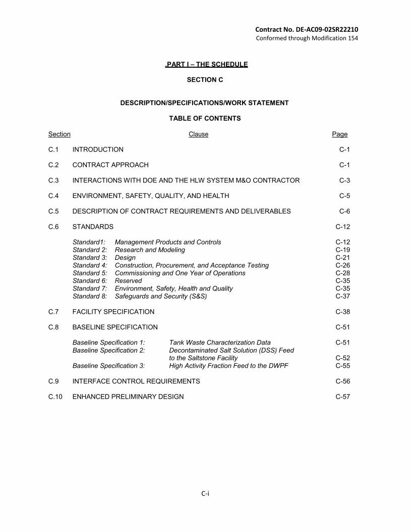
TABLE OF CONTENTS
Section Clause Page
C.1 INTRODUCTION C-1
C.2 CONTRACT APPROACH C-1
C.3 INTERACTIONS WITH DOE AND THE HLW SYSTEM M&O CONTRACTOR C-3
C.4 ENVIRONMENT, SAFETY, QUALITY, AND HEALTH C-5
C.5 DESCRIPTION OF CONTRACT REQUIREMENTS AND DELIVERABLES C-6
C.6 STANDARDS C-12
Standard1: Management Products and Controls C-12 Standard 2: Research and Modeling C-19 Standard 3: Design C-21 Standard 4: Construction, Procurement, and Acceptance Testing C-26 Standard 5: Commissioning and One Year of Operations C-28 Standard 6: Reserved C-35 Standard 7: Environment, Safety, Health and Quality C-35 Standard 8: Safeguards and Security (S&S) C-37
C.7 FACILITY SPECIFICATION C-38
C.8 BASELINE SPECIFICATION C-51
Baseline Specification 1: Tank Waste Characterization Data C-51 Baseline Specification 2: Decontaminated Salt Solution (DSS) Feed
to the Saltstone Facility C-52 Baseline Specification 3: High Activity Fraction Feed to the DWPF C-55
C.9 INTERFACE CONTROL REQUIREMENTS C-56
C.10 ENHANCED PRELIMINARY DESIGN C-57
C - 1
Contract No. DE-AC09-02SR22210 Conformed through Modification 154
PART I – THE SCHEDULE
SECTION C
DESCRIPTION/SPECIFICATIONS/WORK STATEMENT
C.1 INTRODUCTION
The Section C Statement of Work for this Contract is divided into nine subsections: (C.1) Introduction;
(C.2) Summary of contract approach;
(C.3) Summary of interactions with the Contractor;
(C.4) Summary of environment, safety, quality, and health requirements;
(C.5) Description of Contract requirements and deliverables defined in the statement of work;
(C.6) Standards/requirements for execution of the project;
(C.7) Description of basic facility design specifications;
(C.8) Baseline for operational specifications; and
(C.9) Summary of the Interface Control Requirements.
C.2 CONTRACT APPROACH
To accomplish the High Level Waste (HLW) processing mission at the Savannah River Operations Office (SR), the DOE will perform salt waste processing via two primary contracts. The first is the current site Managing and Operating (M&O) Contract, responsible for ensuring safe operation of the HLW System including the Defense Waste Processing Facility (DWPF), the Saltstone Facility, HLW Tank Farm, HLW evaporators, and the Effluent Treatment Facility (ETF). The second separate contract will involve Contractor/Contractors responsible for designing, constructing, and commissioning, of a HLW SWPF based on Caustic-Side Solvent Extraction (CSSX) technology. There are several initiatives that will be pursued under the M&O contract that will affect many parameters of the SWPF. These initiatives involve deployment of existing infrastructure to process and dispose of portions of the salt waste in the tank farms. If successful, they may eliminate the need for the alpha removal process step in the new facility and affect the quantity and concentration of waste to be processed by the SWPF.
The objective of the SWPF is to design, construct, and commission an SWPF to process salt waste. (NOTE: The SPP has been renamed the “SWPF Project”. Any reference in this contract to SPP is a reference to the SWPF Project.) The SWPF Contractor/Contractors (hereinafter referred to as the Contractor(s)”) has full responsibility for the SWPF from the transfer of technology development and Design Information through the completion of transition to long term operation of the facility. A phased contract approach, as outlined in Section B, will be employed. Following facility completion and commissioning per this contract, long term operation of the SWPF will be performed under a separate contract. The SWPF Contract will focus on Contract award for design, construction, and startup/commissioning, and turnover of the SWPF.
The SWPF Web Page (password protected) contains pre-conceptual design information for a full- scale production facility and conceptual design information for a research scale integrated pilot facility. This technical information will hereafter be referred to collectively as SWPF Design Data. Prior to Contract award, the SRS M&O Contractor will maintain the SWPF Design Data, and continue to support technology development efforts. All SWPF Design Data will be transitioned from the M&O Contractor to the Contractor(s) subsequent to Contract award.
C - 2
Contract No. DE-AC09-02SR22210 Conformed through Modification 154
The contract will be performed in the phases defined in Section B, Supplies or services and Price/Costs. In performance of this contract, the Contractor(s) will review the SWPF Design Data and develop a Conceptual Design and estimated cost and schedule range for a SWPF. The facility shall be designed to provide production capability. For the conceptual design competition, each Engineering, Procurement, and Construction (EPC) shall design a facility with a through put capacity of 15% of the flowsheet for a full-scale facility. Waste feed specifications and process product specifications will not be finalized at the time of contract award. Nominal data points for these parameters will be provided in this Request for Proposal to support proposal preparation only. Actual specifications against which facility performance will be measured are to be developed in conjunction with DOE and the Site M&O Contractor as a deliverable during the conceptual design phase of this contract.
Each design shall provide operations equipment and facility footprint for a front-end actinide, strontium (Sr), and suspended solids removal process unit operation. DOE is exploring alternatives that may perform this operation prior to feeding the salt waste to the SWPF. This equipment should therefore be designed to minimize the impact of deleting this unit operation from this facility at any time prior to start of final design. The impact to costs and schedule activities associated with the design, construction, start-up, and commissioning of the alpha removal option shall be identified in the cost and schedule range estimates.
The EPC contractors will perform a sensitivity analysis of cost and schedule verses the following facility scales: 01%, 05%, 10%, and 20%. The purpose of these studies will be to determine the impacts of increasing or decreasing the size of the facility. Specific break points, if any, where significant cost and or schedule benefits or penalties are incurred with changes in facility scale should be identified by the analysis.
DOE will select a facility scale for which the contractor shall complete Conceptual Designs and Critical Decision (CD–1) packages. Preliminary Design, Preliminary Documented Safety Analysis (PDSA), and establishment of the Project Baseline Cost Estimate and Schedule are completed next. The selected Contractor will be required to identify an organization/contractor that will perform start up, and commissioning activities. These services may be self performed or contracted out. In either case the performing organization shall be identified and participate as part of the IPT within four months after the start of preliminary design.
The contract will continue with Final Detailed design including the Final Documented Safety Analysis (DSA), construction, and start up/commissioning management. Construction and procurement activities are to be competitively bid (single or multiple contracts as determined most efficient by the contractor) on fixed price basis where possible. The contractor will be responsible for acceptance testing, startup/and commissioning (either self-performed or contracted as discussed above). DOE will task the Site M&O Contractor to provide the waste feed and receive product streams from the facility while providing interface support and services to the startup and commissioning organization. The contractor will ensure these evolutions are conducted in accordance with all required environmental, safety, quality, and health actions. From Contract Award, the Contractor will be the design agent responsible for the SWPF design. DOE will expect full Contractor accountability for performance, cost, and schedule throughout the Contract period of performance. Approval of and/or comments on deliverables will be provided to the EPC’s by DOE. The SWPF Design Data provides a proposed solution to meet HLW disposal requirements that has potential for optimization/value engineering. DOE will seek to improve the SWPF by offering incentives to the Contractor(s) to optimize project performance, cost, and schedule, including the process design, facility design, and technologies.
DOE will evaluate Contractor(s) performance against Contract requirements and review Contractor(s) proposed changes to Contract requirements, but will not accept performance or approve changes that adversely impact overall system-level performance, life-cycle cost, or
C - 3
Contract No. DE-AC09-02SR22210 Conformed through Modification 154
schedule. Proposed changes must be substantiated with rationale and justification for implementation including proof of viability and technical maturity. DOE approval shall be obtained prior to implementation. All potentials for optimization/value engineering including those that could increase the scope of the project should be evaluated for the overall merit. DOE, however, reserves the unilateral right to disapprove change it considers to be adverse, inadequately substantiated, and/or not in the government’s best interest.
C.3 INTERACTIONS WITH DOE AND THE HLW SYSTEM M&O CONTRACTOR
(a) DOE and the site M&O Contractor have specific responsibilities and defined interactions with the Contractor(s). DOE will use an Integrated Project Team (IPT) approach to manage interactions between DOE, the Contractor(s), the R&D organization, and the Site M&O contractor. This approach will: clearly define roles and responsibilities, encourage a common vision with supporting goals and missions for each participant; promote the principles of teamwork, mutual respect, openness, trust, professionalism, and understanding; and include joint commitments to: (1) Maintain high safety performance; (2) Complete the SWPF on schedule and within cost; (3) Eliminate barriers to an efficient and more cost-effective project; (4) Promote innovation; (5) Improve communication and understanding; (6) Provide early identification and recovery from performance problems; (7) Resolve conflicts through a coordinated work effort that avoids adversarial
relationships; and (8) Reinforce the partnered relationship through honest feedback and continual
improvement.
The Contractor(s) shall provide resources necessary to establish and implement the IPT approach. The Contractor(s) shall be responsible for actively participating in the IPT in a constructive manner.
(b) DOE is responsible as the “Owner” and “Regulator” of the SWPF. (1) As the Owner, DOE will:
(i) Establish requirements, administer the Contract and confirm that the
Contractor(s) meet Contract requirements; (ii) Ensure the SWPF is integrated into the overall HLW System; (iii) Approve all changes to the technical baseline; e.g. such as system-level
flowsheet, process flow diagrams, interface control documents (ICDs) (physical system interface definition), feed characteristics, and product specifications and future operations baseline;
(iv) Perform design, construction and operability oversight of the SWPF and, where required, engage other contractors to provide design and construction and operability oversight of the SWPF;
(v) Perform review (and where required, engage other contractors) of Contractor(s) environmental, safety, quality, and health actions for compatibility and integration with site wide Environment, Safety, Health and Quality (ESH&Q) activities;
(vi) Inspect and accept the SWPF; (vii) Manage project progression through the critical decision process (DOE
Order 413.3A, Program and Project Management for the Acquisition of Capitol Assets);
(viii) Provide Quality Assurance (QA) oversight; (ix) Require compatibility of reporting and management systems; and (x) Act as the interface for all information transferred between the EPC and M&O
C - 4
Contract No. DE-AC09-02SR22210 Conformed through Modification 154
Contractors. All information will be provided from the M&O to DOE. DOE will then provide the information to the EPC contractors.
Information requests from the EPC contractors will be provided to DOE who will then provide the request to the M&O or other appropriate party. DOE will attend and participate in all oral presentations between the M&O and EPC contractors related to this project.
(2) As the Regulator, DOE will regulate radiological, nuclear, and process safety, and non-radiological worker safety and health.
(3) Provide for conduct of the R&D activities identified in the R&D Program Plan. These activities will be managed by DOE’s Tank Focus Area for DOE-Savannah River (DOE-SR) and will employ the DOE and National Laboratories, private vendors, and/or universities.
(c) The Site M&O Contractor will: (1) Transition the SWPF Design Data to the Contractor(s) upon Contract award. (2) Provide site services to the Contractor(s) as directed by DOE (see Section C.9,
Interface Control Requirements). (3) Provide technical support to DOE when requested to review specified contract
deliverables and provide to DOE their recommended changes and or comments. (4) Process permit modifications/notifications/applications as necessary to include the
SWPF in existing site-wide Permits. (i.e. Air and Waste Water Permits) (Permits for the SWPF that will be independent of existing site permits will be the contractor’s responsibility).
(5) Provide R&D support through the Savannah River National Laboratory as directed by DOE.
(6) Perform work to qualify HLW glass as required and directed by DOE. (7) Team with the contractor(s) and DOE to develop and define the final Waste Feed
Strategy and Product and Secondary Waste Specification.
(d) The SWPF Contractor(s) shall: (1) Perform the requirements of this Contract, integrating activities with DOE, and the
Site M&O Contractor. (2) In cooperation with DOE-SR (as lead), and the Site M&O Contractor establish an
interface management process to assure effective control of technical, administrative, and regulatory interfaces.
(3) Support DOE in external communications on the SWPF with stakeholders, regulators, and other special interest groups.
(4) Transition the commissioned SWPF to an Operating Contractor after one year of successful operation.
(5) Provide DOE or its designee(s) access to the Contractor(s) (and its subcontractors/suppliers, at any level) records, premises, activities, and materials in possession or use related to the SWPF, as necessary to effectuate the responsibilities of DOE while conducting assessments, independent reviews, audits, and/or surveillance.
(6) Team with the M&O contractor and DOE to develop and define the final Waste Feed Strategy and Product and Secondary Waste Specification.
(7) Be responsible for ensuring all R&D necessary to support their design is planned and performed.
C - 5
Contract No. DE-AC09-02SR22210 Conformed through Modification 154
C.4 ENVIRONMENT, SAFETY, QUALITY, AND HEALTH
(a) The Contractor(s) will provide a SWPF that processes DOE-owned highly radioactive salt waste including small quantities of entrained solids and sludge. In order to deliver the SWPF within the appropriate level of controls consistent with the hazards to be encountered, the Contractor(s) shall establish and maintain an ISMS that meets the requirements of DOE Policy 450.4, Safety Management System Policy and is compatible with site requirements as defined in section C.6 Standard 7. Implementation of the ISMS shall be verified in accordance with the DOE Policy and its supporting DOE Guides.
The Contractor(s) shall be responsible for protecting human health and the environment from radioactive or, hazardous materials, and hazardous waste contamination; and non- radiological WS&H from conventional, construction, industrial and occupational hazards. The Contractor shall also provide safe and healthful working conditions for employees, subcontractors and all other personnel under the Contractor’s control who work in the general vicinity of the Contractor site and facilities.
The Contractor(s) shall comply with all applicable Federal, DOE, State, and local regulations and requirements for: (1) Non-radiological worker safety and health; (2) Radiological, nuclear, and process safety; and (3) Environmental protection.
(b) DOE will provide existing ESH&Q documentation with the SWPF Design Data and supporting information, to allow the Contractor(s) to review, modify, and implement required ESH&Q actions under this Contract.
(c) The regulatory environment for this Contract is structured into four principal areas of responsibility and requirements on Contractor(s) performance. Detailed Contractor(s) performance requirements are provided in section C.6 Standard 7.
(1) Non-Radiological Worker Safety and Health: DOE will regulate non-radiological worker
safety and health. The Contractor(s) shall develop and implement the SWPF specific WS&H program.
(2) Radiological, Nuclear, and Process Safety: DOE will regulate radiological, nuclear, and process safety to ensure that the Contractor(s) provides for and operates within the required levels of public and worker protection. The Contractor(s) shall develop and implement SWPF specific radiological, nuclear, and process safety program that can readily be integrated into existing site programs after facility commissioning.
(3) Quality Assurance: DOE will oversee all Contractor(s) performance in accordance with a
Contractor(s)-developed DOE-approved program. The Contractor(s) shall develop and implement an integrated SWPF specific QA Program, supported by documentation that describes overall implementation of QA requirements. QA requirements associated with the Quality Assurance Requirements and Description Document (QARD), DOE/RW-0333P will not be applied to the activities of this contract.
(4) Environmental Protection: The Contractor(s) shall develop and implement a SWPF
specific environmental protection program. In conjunction with DOE and or the Site M&O the Contractor(s) shall prepare all required permit applications, and obtain all necessary permits for the SWPF. (M&O will assist when the SWPF must be included in existing sitewide permits. The Contractor(s) will be responsible for SWPF permits that stand alone)
C - 6
Contract No. DE-AC09-02SR22210 Conformed through Modification 154
(i) DOE is responsible for meeting compliance obligations under the National Environmental Policy Act of 1969 (NEPA). If proposed Contractor actions are outside the analysis performed for the Final Supplemental Environmental Impact Statement for High Level Waste Salt disposition Alternatives at Savannah River, and/or related supplement analyses, the Contractor(s) shall provide technical information and support to DOE for NEPA compliance on the proposed Contractor(s) actions.
(ii) The U.S. Environmental Protection Agency (EPA), and/or the South Carolina Department of Health and Environmental Control (SCDHEC) will regulate radioactive and non-radioactive air emissions. The Contractor shall support integration within the Savannah River Site (SRS)-wide air compliance framework, including the Savannah River Air Operating Permit.
(d) The Defense Nuclear Facilities Safety Board (DNFSB) is responsible for nuclear safety
oversight authority of DOE and its activities related to the SWPF. As directed by the Contracting Officer, the Contractor(s) shall conduct activities in accordance with DOE commitments to the DNFSB, which are contained in implementation plans and other DOE correspondence to the DNFSB. The Contractor(s) shall support preparation of DOE responses to DNFSB issues and recommendations that affect Contract scope. As directed by the Contracting Officer, the Contractor(s) shall fully cooperate with DNFSB and provide access to work areas, personnel, and information, as necessary. The Contractor(s) shall maintain a document process consistent with the DOE Manual on interface with the DNFSB (DOE Manual 140.1-1B, Interface with the Defense Nuclear Facilities Safety Board) and shall ensure that these requirements are followed by themselves and all subcontractors.
C.5 DESCRIPTION OF CONTRACT REQUIREMENTS AND DELIVERABLES
The Contractor(s) shall perform the following major activities:
Transition of SWPF Design Data , Perform Conceptual Design, estimate cost and schedule range for the project and a sensitivity Analysis of cost and schedule verses facility scale and through put;
Continuation of Design to complete Preliminary Design and establish Project Cost and Schedule Baseline;
Performance of Facility and Process Final Design, Construction and Procurement for building the facility. Acceptance, start-up, Commissioning, and Turnover of the completed facility. Financial closeout of the project.
Summary-level requirements for each of these activities are provided in this section, with additional requirements provided in Sections C.6, Standards; C.7, Facility Specification, C.8, Operational Specifications; and C.9, Interface Control Requirements. Best commercial practices shall apply when a Standard, Specification, or Interface Control Requirements are not provided.
(a) Design Transition: The Contractor(s) shall prepare a detailed transition plan, install Contractor management systems and evaluate the SWPF Design Data and supporting information. (1) Plan for Transition: The Contractor(s) shall submit a plan for transition to DOE in
accordance with Standard 1, Management Products and Controls.
(2) Receive the SWPF Design Data and Supporting Information: The Contractor(s) shall receive the SWPF Design Data and supporting information from the Site M&O Contractor as described in Section J, Attachment H, Listing of SWPF Pre- Conceptual Design and Supporting Information.
(3) Due-diligence Reviews: The Contractor(s) shall evaluate the SWPF Design Data and supporting information as part of the Contractor’s responsibility as design agent.
C - 7
Contract No. DE-AC09-02SR22210 Conformed through Modification 154
Key areas of review include: (i) All process and facility design documentation and analyses; (ii) Technology planning and testing information including the R&D Program Plan
and completed R&D results; (iii) Waste product strategies; (iv) Environmental permitting documentation (e.g., Industrial Waste Water
Permit, Air Permits);
(v) Hazards and safety analysis information, authorization basis, and safety standards; and
(vi) Safeguards and Security (S&S) requirements.
(4) Project Baseline: The Contractor(s) shall develop the SWPF Project Baseline range as
part of the SWPF Conceptual Design followed by the SWPF Baseline Cost Estimate as part of Preliminary Design in accordance with requirements in Standard 1, Management Products and Controls and DOE Order 413.3A, Program and Project Management for Acquisition of Capitols Assets.
(b) Facility and Process Design: The Contractor(s) shall prepare all design documents and required supporting information. (1) Design Process: The Contractor(s) shall prepare all design documents and required
supporting information.
(2) Design Requirements: The Contractor(s) shall ensure that the facility is designed to meet all requirements, and that these requirements are captured in a single location to achieve a systematic approach to design. The Contractor shall ensure the design is compatible with existing site facilities, practices, and policies to ensure smooth transition of operation responsibility to the operations contractor upon completion of this contract.
(3) Design Documents: The Contractor(s) shall design the SWPF (Alpha and Cesium
Separations, and balance of plant facilities) consistent with the functional requirements identified in Standard 2, Research, Technology, and Modeling, Standard 3, Design, Section C.7, Facility Specifications, Section C.8, Operational Specifications, and Section C.9, Interface Control Requirements.
(4) Salt Processing Project Optimization: The Contractor(s) shall perform optimization as
described in Standard 3, Design.
(5) Design Reviews: The Contractor(s) shall conduct periodic design, constructability, and operability reviews to status the design activities, and resolve design oversight comments from DOE in accordance with Standard 3, Design.
Additional requirements are provided in Standard 3, Design.
(c) Construction Management and Procurement: The Contractor shall plan and manage execution of all construction, procurement, and acceptance testing activities, both contracted and self-performed. (1) Provide a Construction, Procurement, and Acceptance Testing Plan; (2) Identify all long lead procurement actions and describe the contracting approach and
method of performance; (3) Procure all required material and equipment; (4) Prepare bid and work packages; (5) Manage all required construction; and
C - 8
Contract No. DE-AC09-02SR22210 Conformed through Modification 154
(6) Manage the construction site and ensure all support services required by construction and testing are provided.
Additional requirements are provided in Standard 4, Construction, Procurement, and Acceptance Testing.
(d) Acceptance Testing: The Contractor shall provide integrated acceptance test plans (System Operational Tests and Integrated System Operational Tests) and procedures for DOE review and comment.
Additional requirements for acceptance testing are provided in Standard 5, Commissioning and One Year of Operations.
(e) Facility Start-up/Commissioning: The Contractor shall start up, commission, demonstrate operational performance, and transition the SWPF to the long-term operations contractor.
Additional requirements are provided in Standard 5, and Commissioning and One Year of Operations.
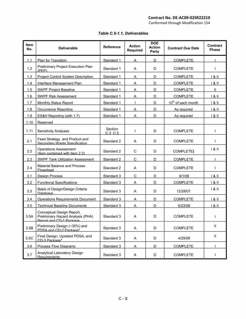
(f) Table C.5-1.1, Deliverables, summarizes the specific deliverables the Contractor(s) shall provide to DOE. Neither the DOE review of the deliverables nor the decision of the DOE to proceed with construction or commissioning shall impose any responsibility on the DOE for adequacy, quality or completeness of the deliverables. The Contractor(s) remains solely responsible for the adequacy, quality and completeness of such work and the performance of the SWPF under this Contract.
Unless otherwise specified, DOE will provide written comments to the Contractor(s) within 10 days of receipt of the deliverable identified in Section C, Statement of Work. Written comments on safety analysis documentation will be provided to the Contractor within 30 days of receipt of the documentation, and durations for DOE review, comment, and approval of Critical Decision Packages will be in accordance with the approved baseline schedule. DOE will utilize other contractors and/or organizations to assist their review. The SWPF Contractor will only accept and respond to comments from and/or endorsed by DOE.
If requested in writing by DOE, the Contractor(s) shall address all DOE mandatory comments and resubmit the deliverable within 30 days after receipt of DOE comments.
Any deliverable due date falling on a weekend or federal holiday shall be considered due on the following workday. Any proposed change in the project baseline must be reviewed and approved by DOE in accordance with Parsons and DOE change control procedures
(g) DOE Directed Changes to the Statement of Work, Captured Via CLIN 0009 (Scope moved to CLIN 0005AA under Modification 116): The Contractor shall comply with all DOE directed changes to the Statement of Work incorporated into the Contract via modifications. The changes will be incorporated into the contract in Section J “List of Attachments,” Attachment L “DOE Directed Changes to the Statement of Work.”
C - 9
Contract No. DE-AC09-02SR22210 Conformed through Modification 154
Table C.5-1.1, Deliverables
Item No.
Deliverable
Reference Action Required
DOE Action Party
Contract Due Date
Contract Phase
1.1 Plan for Transition Standard 1 A D COMPLETE I
1.2 Preliminary Project Execution Plan (PEP)
Standard 1
A
D
COMPLETE
I
1.3 Project Control System Description Standard 1 A D COMPLETE I & II
1.4 Interface Management Plan Standard 1 A D COMPLETE I & II
1.5 SWPF Project Baseline Standard 1 A D COMPLETE II
1.6 SWPF Risk Assessment Standard 1 A D COMPLETE I & II
1.7 Monthly Status Report Standard 1 I D 10th
of each month I & II
1.8 Occurrence Reporting Standard 1 A D As required I & II
1.9 ES&H Reporting (with 1.7) Standard 1 A D As required I & II
1.10 Reserved
1.11
Sensitivity Analyses Section C 2 C 5
I
D
COMPLETE
I
2.1 Feed Strategy and Product and Secondary Waste Specification
Standard 2
A
D
COMPLETE
I
2.2 Operations Assessment (Item combined with Item 2 3)
Standard 2
C
D
COMPLETE) I & II
2.3 SWPF Tank Utilization Assessment Standard 2 C D COMPLETE I
2.4
Material Balance and Process Flowsheet
Standard 2
A
D
COMPLETE
I
3.1 Design Process Standard 3 C D 9/1/08 I & II
3.2 Functional Specifications Standard 3 A D COMPLETE I & II
3.3
Basis of Design/Design Criteria Database
Standard 3
A
D
12/28/07
I & II
3.4 Operations Requirements Document Standard 3 A D COMPLETE I & II
3.5 Technical Baseline Documents Standard 3 A D 6/23/08 I & II
3.5A Conceptual Design Report, Preliminary Hazard Analysis (PHA) Report and CD-1 Package
Standard 3
A
D
COMPLETE
I
3.5B
Preliminary Design (~35%) and PDSA and CD-2 Package*
Standard 3
A
D
COMPLETE
II
3.5C
Final Design, Updated PDSA, and CD-3 Package*
Standard 3
A
D
4/29/08
II
3.6 Process Flow Diagrams Standard 3 A D COMPLETE I
3.7
Analytical Laboratory Design Requirements
Standard 3
A
D
COMPLETE
I
C - 10
Contract No. DE-AC09-02SR22210 Conformed through Modification 154
Item No.
Deliverable
Reference Action Required
DOE Action Party
Contract Due Date
Contract Phase
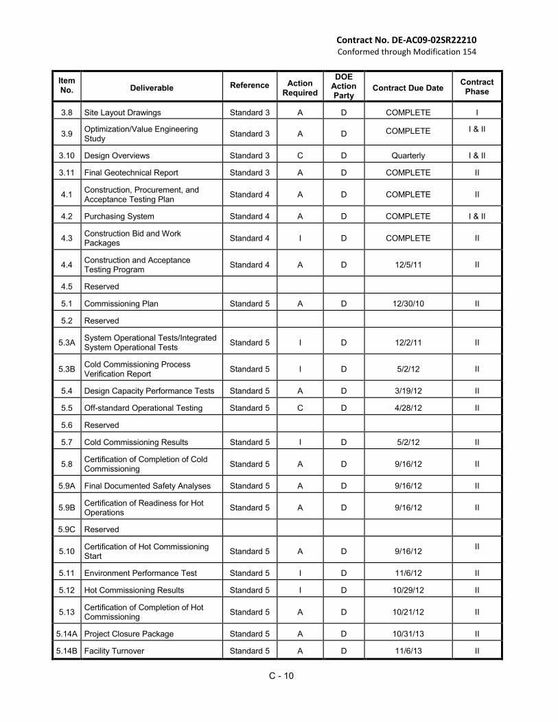
3.8 Site Layout Drawings Standard 3 A D COMPLETE I
3.9
Optimization/Value Engineering Study
Standard 3
A
D COMPLETE I & II
3.10 Design Overviews Standard 3 C D Quarterly I & II
3.11 Final Geotechnical Report Standard 3 A D COMPLETE II
4.1
Construction, Procurement, and Acceptance Testing Plan
Standard 4
A
D
COMPLETE
II
4.2 Purchasing System Standard 4 A D COMPLETE I & II
4.3
Construction Bid and Work Packages
Standard 4
I
D
COMPLETE
II
4.4
Construction and Acceptance Testing Program
Standard 4
A
D
12/5/11
II
4.5 Reserved
5.1 Commissioning Plan Standard 5 A D 12/30/10 II
5.2 Reserved
5.3A System Operational Tests/Integrated System Operational Tests
Standard 5
I
D
12/2/11
II
5.3B
Cold Commissioning Process Verification Report
Standard 5
I
D
5/2/12
II
5.4 Design Capacity Performance Tests Standard 5 A D 3/19/12 II
5.5 Off-standard Operational Testing Standard 5 C D 4/28/12 II
5.6 Reserved
5.7 Cold Commissioning Results Standard 5 I D 5/2/12 II
5.8 Certification of Completion of Cold Commissioning
Standard 5
A
D
9/16/12
II
5.9A Final Documented Safety Analyses Standard 5 A D 9/16/12 II
5.9B Certification of Readiness for Hot Operations
Standard 5
A
D
9/16/12
II
5.9C Reserved
5.10
Certification of Hot Commissioning Start
Standard 5
A
D
9/16/12
II
5.11 Environment Performance Test Standard 5 I D 11/6/12 II
5.12 Hot Commissioning Results Standard 5 I D 10/29/12 II
5.13
Certification of Completion of Hot Commissioning
Standard 5
A
D
10/21/12
II
5.14A Project Closure Package Standard 5 A D 10/31/13 II
5.14B Facility Turnover Standard 5 A D 11/6/13 II
C - 11
Contract No. DE-AC09-02SR22210 Conformed through Modification 154
Item No.
Deliverable
Reference Action Required
DOE Action Party
Contract Due Date
Contract Phase
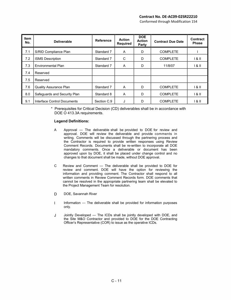
7.1 S/RID Compliance Plan Standard 7 A D COMPLETE I
7.2 ISMS Description Standard 7 C D COMPLETE I & II
7.3 Environmental Plan Standard 7 A D 11/8/07 I & II
7.4 Reserved
7.5 Reserved
7.6 Quality Assurance Plan Standard 7 A D COMPLETE I & II
8.0 Safeguards and Security Plan Standard 8 A D COMPLETE I & II
9.1 Interface Control Documents Section C.9 J D COMPLETE I & II
* Prerequisites for Critical Decision (CD) deliverables shall be in accordance with DOE O 413.3A requirements.
Legend Definitions:
A Approval — The deliverable shall be provided to DOE for review and
approval. DOE will review the deliverable and provide comments in writing. Comments will be discussed through the partnering process and the Contractor is required to provide written responses using Review Comment Records. Documents shall be re-written to incorporate all DOE mandatory comments. Once a deliverable or document has been approved upon by DOE, it shall be placed under change control and no changes to that document shall be made, without DOE approval.
C Review and Comment — The deliverable shall be provided to DOE for
review and comment. DOE will have the option for reviewing the information and providing comment. The Contractor shall respond to all written comments in Review Comment Records form. DOE comments that cannot be resolved in the appropriate partnering team shall be elevated to the Project Management Team for resolution.
D DOE, Savannah River
I Information — The deliverable shall be provided for information purposes
only.
J Jointly Developed — The ICDs shall be jointly developed with DOE, and
the Site M&O Contractor and provided to DOE for the DOE Contracting Officer’s Representative (COR) to issue as the operative ICDs.
C - 12
Contract No. DE-AC09-02SR22210 Conformed through Modification 154
C.6 STANDARDS
This Section consists of the following Standards, which describe requirements for managing, constructing, commissioning the SWPF, and related activities:
Standard 1: Management Products and Controls Standard 2: Research and Modeling Standard 3: Design Standard 4: Construction, Procurement, and Acceptance Testing Standard 5: Commissioning and One Year of Operations Standard 6: Reserved Standard 7: Environment, Safety, Quality, and Health Standard 8: Safeguards and Security
Standard 1: Management Products and Controls
This Standard describes the management products and controls required during the Contract period. DOE Order 413.3A, Program and Project Management for Acquisition of Capitol Assets, with accompanying requirements and practices manuals provides the overall direction for DOE and Contractor project management activities, including baseline management, life-cycle planning, requirements management, and technical integration. The Contractor shall comply with DOE Order 413.3A throughout the performance of the contract, and is encouraged to use any existing corporate-level project management system that meets the requirements of the DOE Order and this Standard.
(a) Transition Plan: The Contractor shall provide for DOE review and approval (Table C.5-1.1, Deliverable 1.1) an overall plan and schedule for achieving a smooth and expeditious transition of SWPF activities and design assets/products from the M&O Contractor to the EPC Contractor(s). Emphasis should be placed on minimizing impacts on SWPF schedule objectives and rapidly performing due-diligence reviews of technical information. This plan shall include, at a minimum, the approach and schedule for: (Note: It is DOE’s expectation that this turnover will be completed in an expeditious manner and should not exceed 4 months duration following contract award.) (1) SWPF staffing plans for each project phase. (2) Execution of necessary subcontracts or support needs including subcontractors/support
from the Site M&O Contractor. (3) Performing due-diligence reviews of existing technical information. (4) Establishment of project management systems. (5) Development of an integrated SWPF scope, schedule, and cost baseline.
(b) Project Execution Plan: Each Contractor shall prepare a Preliminary PEP in accordance with DOE Order 413.3A. (Table C.5-1.1, Deliverable 1.2). DOE will integrate these documents into the PEP for the project.
(c) Project Control System:
(1) Project Control System Definition: The Contractor shall establish, maintain, and use a
Project Control System that supports successful execution of the SWPF during all activities (e.g., transition, design, construction, and commissioning). The System must produce accurate planning, budgeting, reporting, and change control data and meet the requirements of DOE Order 413.3A. The Contractor shall provide all necessary technical information and support related to the SWPF to enable DOE to proceed with the critical decision process of the Order and to enable DOE to meet the data requirements of the integrated planning, accountability, and budgeting system.
C - 13
Contract No. DE-AC09-02SR22210 Conformed through Modification 154
(2) Project Control System Description: The Contractor shall provide for DOE approval (Table C.5-1.1, Deliverable 1.3) a Project Control System Description. Upon approval by the Contracting Officer, the Contractor shall fully implement the project control system. The Project Control System Description shall describe the management processes and controls utilized to manage and control work and complete Contract requirements. The Project Control System Description shall, at a minimum, include:
(i) The work breakdown structure (WBS) including “dictionary” descriptions of
elements of work. (ii) The organizational breakdown structure, including roles and responsibilities of
each major organization and identification of key management personnel. (iii) The organizational and management interfaces between the Contractor and the
Site M&O Contractor. (iv) The approach the Contractor will use to implement the requirements of DOE
Order 413.3A pertaining to project control processes including: (A) Systems engineering; (B) Configuration management; (C) SWPF process change control; (D) Baseline change control; (E) Contract management; (F) Performance measurement; (G) Information and reporting; (H) Interface management; (I) Work authorization; (J) Work management; (K) Risk management; (L) Construction project management; (M) Communications and stakeholder involvement; (N) Start up, and Commissioning; (O) Project Financial Closure.
(v) The technical, cost, and schedule baseline development process and the hierarchy of documents that will be used to describe and maintain that baseline.
(vi) The process the Contractor intends to use to complete design and engineering activities, including standards, design guides, and procedures for document control, configuration control, change control, and quality control.
(vii) A brief summary of any supporting procedures and plans that will be used to implement the project including applicable engineering standards, practices, or guides.
(3) Project Controls Configuration Management: A revised Project Control System Description shall be submitted for DOE approval (Table C.5-1.1, Deliverable 1.3) when significant changes are required in management processes (e.g., prior to start of construction or prior to start of commissioning). The CO may direct additional compliance reviews to determine whether the Contractor is operating the system efficiently and producing accurate planning, budgeting, reporting, and change control data. The Contractor shall provide the CO or designated representatives with access to all pertinent records, data, and plans for purposes of initial approval, approval of proposed changes, and the ongoing operation of the project control system.
(4) Interface Management: In concert with DOE and the Site M&O Contractor, the Contractor(s) shall develop and implement an interface management plan. The plan shall be submitted for DOE review and approval (Table C.5-1.1, Deliverable 1.4). The interface management plan shall provide the process to: (i) Recognize the DOE role as the owner of the SWPF and as the final decision
authority for any interface issues that are not resolved between the other parties.
C - 14
Contract No. DE-AC09-02SR22210 Conformed through Modification 154
(ii) Define the scope of each interface and provide a brief description of the required deliverables (products, documents, procedures, services, etc.).
(iii) Define organizational points of contact for participants.
(iv) Define interface requirements, controls, and applicable source documents for each interface.
(v) Involve appropriate SRS organizations in the integration, review and approval of interface requirements and changes (leadership of interface groups should be chaired by DOE or the involved party with the primary responsibility for management of the receipt of material, goods or service, unless otherwise appropriate).
(vi) Develop ICD to define and document interface details and agreements. Any changes to established ICDs shall be processed through the appropriate change control process and, if necessary, contract changes.
(vii) Involve individuals with the appropriate level of organizational responsibility and authority to assure the interface is implemented and functioning.
(viii) Identify, track, and elevate issues for management review on a regular basis.
(5) SWPF Baseline Development: Baseline Requirements: The Contractor shall develop and maintain an integrated and traceable scope, schedule, and cost baseline for the SWPF to be delivered to DOE for approval. Initial submittal shall be as a Baseline range following Conceptual Design. The Project Baseline will be submitted and approved following completion of Preliminary Design (Table C.5-1.1, Deliverable 1.5, Milestone M1). The baseline shall include the SWPF project technical requirements; definition of work scope to achieve those requirements; schedule to implement project work scope; cost to implement project work scope on the projected schedule; and assessment of the risks to achieving the baseline. The SWPF Project Baseline shall be summarized in the PEP and will be supported by additional baseline documentation, as necessary. Salt Processing Project Baseline Description: The SWPF Project Baseline description shall contain sufficient scope, schedule, and cost information to support the annual budget process. The SWPF Project Baseline description shall, at a minimum, contain: (i) Scope:
(A) SWPF functional logic showing the relationships among SWPF project activities and other SRS activities. The requirements shall also depict the relationships by facility and interdependencies among the top-level SWPF activities.
(B) Summary of SWPF top-level technical requirements with reference to supporting requirements documents and specifications (e.g., Sections C.7, C.8, and C.9; Functional Specification; Basis of Design/Design Criteria Database; and Operations Requirements Document).
(C) Key Assumptions List that includes assumptions made by the Contractor(s), especially those that indicate DOE or Site M&O Contractor input or output with performance need dates and quantities or milestones. The assumptions define the basis for the SWPF schedule and cost baseline. ICDs shall be used to document services to be provided.
(D) Key DOE activities and decision points that describe all DOE activities, including critical decisions (DOE Order 413.3A), other decision points, and regulatory actions that must be accomplished for the Contractor’s plan to be successful. The activities, decision points, ISMS implementation verification, and regulatory actions shall be specifically included in either the top-level or lower-level logics).
(E) Salt processing process description and baseline.
C - 15
Contract No. DE-AC09-02SR22210 Conformed through Modification 154
(ii) Schedule: The Contractor shall provide schedule information that meets the requirements of DOE Order 413.3A and the following. Each activity box in the top-level logic shall be further broken down into one or more lower level logic with key milestones and resource profile(s). There shall be a one-to-many relationship between the top-level and the lower-level logic. The schedule updates shall be provided to DOE as an electronic file on Compact Disc-Read
Only Memory (CD-ROM). Additionally, the Contractor shall provide DOE monthly schedule updates and shall work with the Site M&O Contractor and DOE to resolve schedule discrepancies. The schedule shall: (A) Be logic driven and show the duration of tasks, completion milestones,
critical path, and progress on each activity; (B) Demonstrate the methodology utilized to accomplish the work and meet
schedule milestones; (C) Contain sufficient levels of detail to promote understanding of the logical
sequence of activities and identify all interfaces between performing organizations;
(D) Be resource loaded with budget cost, labor hours, skill mix, and quantities, preserved by major groupings, design, construction, start up, and testing progress metrics; and
(E) Be consistent with the information provided in the top-level project logic.
(ii) Cost: The SWPF Project Baseline description shall include a summary of the project cost baseline, a life-cycle cost estimate, and a monthly spending plan for the current Fiscal Year (FY), next FY (FY +1), and one year out (FY+2). The SWPF Project Baseline and supporting documentation package shall be submitted as a written report that contains the following information: (A) Description of the type and purpose of the estimate being performed
including a summary description of facility design, process design, operational concept, and schedule.
(B) Description of the completeness of the facility and process design. (C) Description of the methodology of how the estimate was developed. (D) Description of the WBS and a description of the methodology for its
development. (E) Detailed technical description of the scope to be performed for each of
the WBS elements. This shall include, as a minimum, performance specification(s) and the work activities required, but it shall also identify any work specifically excluded, any constraints or special conditions, ground rules, assumptions, and drivers.
(F) Estimating backup materials, including quantity takeoffs, equipment lists, detailed specifications, plans and drawings, calculations, databases used, historical data, cost estimating relationships, and actual quotes.
(G) Details of indirect cost including field distributable costs and a description of the work covered by indirect costs and how the indirect costs were estimated and developed. Field distributable costs shall be in enough detail to describe what is included. If, for example, a cost calculation per job hour is used, a complete description of the scope covered by the calculation shall be included.
(H) Explanation and description of overhead and general and administrative rates, as well as the elements included.
(I) Description and breakdown of how a standard base rate is burdened to arrive at the estimated hourly rate.
(J) Definitions and delineation for and categorization of costs into labor,
C - 16
Contract No. DE-AC09-02SR22210 Conformed through Modification 154
material, equipment, travel, financial, fee, taxes, contingency, and other. (K) Full delineation of any use of productivity or related factors that clearly
identifies when and where used and basis for the utilization. (L) Written analysis of how contingency/risk was determined. This includes
all pertinent information necessary to understand and perform the calculations. Project Contingency shall be clearly discernable from all other costs and shall be inclusive of all sources for assignment of contingency (i.e. risk assessment, estimating models such as Monte Carlo, estimator standard, etc.). The probability distribution curve and the cumulative probability distribution curve that reflects the costs used to establish cost shall be described.
(i) Estimate history, if the current estimate is a revision to an earlier estimate and a crosswalk between submitted revisions.
(N) Basis of escalation, if applicable. (O) Sub-tier contractor estimates detailing the same information as required
by the Contractor and be traceable to the cost estimate and WBS. (P) Names of the key preparers of the estimate. (Q) Information shall be provided at the level for which it was derived.
(iii) Contingency Utilization Profile: A cumulative project contingency utilization
profile that defines total cumulative Project Contingency utilization against time for the duration of the Contact. This profile shall incorporate all known sources of contingency including that identified within the SWPF risk assessment described below. (A) The cumulative project contingency utilization profile establishes
projected contingency requirements, allocated to each major project phase (design, construction, acceptance testing, cold commissioning, and hot commissioning) and shall be directly traceable and linked to the schedule baseline and cost baseline. The Contractor(s) may utilize all contingency defined in the cumulative project contingency utilization profile up to the limits established for that point of time on the profile.
(B) DOE and the Contractor(s) shall review the Contractor’s utilization of contingency relative to the cumulative project contingency utilization profile on a quarterly basis. The Contractor shall notify DOE, as soon as practicable but at least 30-days in advance, when contingency utilization is projected to exceed the cumulative project contingency utilization profile at any given period in performance. DOE approval shall be required to utilize contingency in excess of the cumulative project contingency utilization profile.
(6) SWPF Risk Assessment: The SWPF risk assessment shall implement the risk management process defined in DOE Order 413.3A requirements and practices manuals and be provided to DOE for approval (Table C.5-1.1, Deliverable 1.6). A quantitative assessment of the SWPF risks shall be maintained. The risk assessment shall identify the major risks to achieving the baseline and the Contractor’s approach for managing those risks. The Contractor(s) shall include risk management status reports in the monthly status to DOE. The risk assessment shall meet the following requirements: (i) Project risks shall be identified (Critical Risk List) and analyzed relative to their
probabilities and consequences; (ii) Risk management actions (either prevention or mitigation) shall be identified and
implemented; (iii) Risk and decision management activities shall be coordinated with DOE,
including agreement as to who should have the risk management lead for each risk;
C - 17
Contract No. DE-AC09-02SR22210 Conformed through Modification 154
(iv) Performance against risk management actions shall be tracked and reported; (v) Project contingency fund requirements shall be calculated as a function of
identified risks; and (vi) Risk associated with ICDs shall be documented and issue resolution plans
prepared.
(7) Maintenance of the Salt Processing Project Baseline: The SWPF baseline description shall be submitted every April for DOE review and approval (Table C.5-1.1, Deliverable 1.5). The SWPF baseline description shall contain a summary of all approved changes to the baseline (scope, schedule, and cost). The summary shall include the serial number of each approved change, the WBS numbers affected, a description of the change, and the net cost and schedule impacts of the change. Annual updates, including the project cost and schedule baseline, shall reflect the most current information and logic and include the information at the same or greater level of detail as provided to DOE in the initial baseline and best available information for SWPF performance.
(d) Integrated Change Control:
(1) Change Control Process: The Contractor(s) shall implement disciplined change
control according to the methods approved in the Project Control System Description (Table C.5-1.1, Deliverable 1.3). Change control and trend monitoring shall be implemented concurrent with DOE approval of the SWPF Project Baseline (Table C.5-1.1, Deliverable 1.5).
(2) Design Changes: Proposed design changes shall also require a technical analysis using process modeling to assess the impact on plant capacity, operability, and throughput. (See Standard 2, Research, Technology, and Modeling.)
(3) Baseline Thresholds: As part of the Project Control System Description (Table C.5-
1.1, Deliverable 1.3), the Contractor(s) shall propose thresholds to define DOE and Contractor change authority. Thresholds do not apply to proposed changes in Target Cost and Target Schedule (for fee calculations as specified in Section B.5 (b)), and fees. DOE approval is required for all such changes.
(e) SWPF Performance and Reporting System:
(1) Baseline Reporting System: The Contractor(s) shall develop a reporting system
that reports project performance on the technical work, schedule, and cost profile defined in the SWPF baseline at a level agreed to by DOE. The requirements and procedures for this system shall be defined in the PEP.
(2) Monthly Status Reports: The Contractor(s) shall prepare status reports, monthly, and transmit to DOE Federal Project Director and to the following email
address: [email protected] by the 15th
calendar day of the following month for information (Table C.5-1.1, Deliverable 1.7), commencing the first month after Contract award. Status reports shall include narrative and performance curves (earned value based on the schedule) for the cost and job hour status (e.g., planned, actual, and forecast percents complete). The percent variances shall be identified and addressed. Status reports shall include data for the total project cost and performance for the major WBS elements. The status report shall also include a written report and briefing that addresses:
(i) Project manager narrative assessment; (ii) Significant accomplishments and progress towards completion of project
goals, objectives, and milestones; (iii) Construction Inspection and Acceptance status (per Standard 4);
C - 18
Contract No. DE-AC09-02SR22210 Conformed through Modification 154
(iv) Comparison of the amount of work completed against the project baseline, including an earned value analysis;
(v) Potential problems, impacts, and alternative courses of action, including staffing issues;
(vi) Performance, using schedule, earned value, and critical path methods, to identify potential schedule deviations and needed corrective actions before they impact the baseline;
(vii) Critical risks, actions planned, and actions taken to address those risks; (viii) Status of decisions, including DOE decisions, and information requirements
for those decisions; (ix) Ninety day forecast for major activities and milestones; (x) Report of proposed changes that impact DOE, site interfaces, or major
project milestones; (xi) Updated baseline schedule (a statused, resource loaded cost performance
measurement schedule) shall be submitted that reflects progress against the baseline. The schedule shall incorporate all approved changes to date. The schedule shall include actual information, including but not limited to, start and finish dates; hours expended; actual costs incurred; units installed; percent complete; and forecast dates;
(xii) Critical path analysis to monitor status of key activities;
(xiii) The performance reporting shall include current period, cumulative and at completion information in terms of budgeted cost of work scheduled, budgeted cost of work performed, actual cost of work performed including a summary of cost trends, and contingency utilization; and
(xiv) A change control section shall be included that summarizes the scope, technical, cost, and/or schedule impacts resulting from any implemented actions. A section shall be included that discusses any known or pending change control submittals.
(3) Occurrence Reporting: The Contractor shall adhere to DOE Manual 232.1-1A,
Occurrence Reporting and Processing of Operations Information with Site specific requirements and methods for notification (Table C.5-1.1, Deliverable 1.8).
(4) Environment, Safety, and Health Reporting: In addition to Occupational Safety and Health Act of 1970, and the Price Anderson Amendments Act of 1988 (10 CFR 820) reporting requirements, the Contractor shall report all events and information specified in DOE Order 231.1, Environment, Safety and Health Reporting. The process and form of reporting will meet the requirements specified in section C.6 Standard 7 Environment, Safety, Quality, and Health. The Contractor process will specify this requirement in Contracts down to the lowest tier subcontractor. The Contractor process will accumulate and provide a single report responding to required information for both the Contractor and all subcontractors (Table C.5-1.1, Deliverable 1.9).
(5) Accident Investigation: The Contractor and, as necessary, all subcontractors shall
support Type A and Type B accident investigations for accidents that may occur during the Contractors activities. The Contractor and all its subcontractors shall establish and maintain readiness to respond to accidents, mitigate potential consequences, assist in collecting and processing evidence, and assist with the accident investigation. This shall include preserving the accident scene and providing support to the accident investigation board.
C - 19
Contract No. DE-AC09-02SR22210 Conformed through Modification 154
Standard 2: Research and Modeling
This Standard describes the R&D Program requirements and process and facility modeling requirements.
(a) R&D Testing Program: (1) R&D Program Plan:
A SWPF R&D Program Plan was developed as part of the Technology Selection Process. The R&D Program Plan describes the research and testing work activities planned to support technology selection; process and facility design, and provide information to support environmental permitting and establishment of the authorization basis. R&D results from this program, both presently completed and future planned will be available to the Contractor(s).
The Contractor(s) will be responsible for ensuring all R&D needed to support their design efforts is performed. The R&D performed per the SWPF R&D Program Plan through FY 02 is one source available to the Contractor(s). The Contractor(s) will be responsible for reviewing the R&D program plan and assessing its adequacy for meeting the design input needs. If the Contractor(s) determine that additional R&D is required, it shall be planned, contracted and managed by the contractor(s) with associated costs included in their design costs. At the contractor’s request and with DOE approval additional R&D activities may be included in the SWPF R&D Program with results shared by both contractors. The Contractor(s) shall focus on the remaining research and testing required for implementation of the Caustic Side Solvent Extraction technology including actinide/Sr removal. They should include all testing necessary to verify SWPF process products will meet waste acceptance characteristics for the DWPF and Saltstone facilities as defined in the SWPF Feed Strategy and Product and Secondary Waste Specification (to be developed by the M&O and the Contractor(s)). The R&D activities will be logically tied to the project baseline and baseline risk assessment described in Standard 1, Management Products and Controls.
(2) Required Development of Waste Feed and Product Definition:
Characterization of HLW Salt Feeds: The Contractor(s) shall team with DOE and the Site M&O Contractor to review the HLW System Waste Characterization Database. Progress and assumptions resulting from the M&O contractor’s alternative salt disposition initiatives shall also be evaluated. From this information, a joint EPC/DOE/M&O Feed Strategy and Product and Secondary Waste Specification for the SWPF shall be developed and presented to DOE for approval. This deliverable shall provide to DOE the contractor(s) endorsement of the technical adequacy of the HLW characterization data or their recommended changes or actions required to conclude waste characterization is adequate to support facility design and the requirements of this contract. (Table C.5-1.1 Deliverable 2.1). Upon DOE approval, these specifications will become the metric for evaluation of facility performance. Open issues identified by this review shall be logically tied to the project baseline and baseline risk assessment described in Standard 1, Management Products and Controls. Additional analysis requirements if needed shall be defined by the Contractor in Contractor Data Request. All analytic results shall be reported to the contractor(s) and to DOE by the Site M&O Contractor prior to inclusion into the HLW Characterization Database.
(3) Process and Facility Modeling Requirements:
The Contractor(s) shall develop and use analytical models to support the design of the
process and facility system, support pre-operational planning assessments, and provide
technical integration with Site M&O Contractor waste feed staging and product acceptance
activities. The Contractor(s) will, at a minimum, develop the following models:
C - 20
Contract No. DE-AC09-02SR22210 Conformed through Modification 154
(4) Operations Assessment Model of the SWPF Plant: The Contractor(s) shall model operations of the facility to verify that the facility design concept incorporates appropriate design and operational features to meet plant capacity requirements and reduce construction and/or operations costs. The scope of the assessment model shall include: sampling and analysis requirements including sample turnaround times; tank capacities and times to conduct individual process steps in unit operations; time for mechanical handling steps; equipment reliability; time estimates for maintenance and repair of facility and process systems; estimated spare equipment inventory; and recommendations to improve reliability and throughput of the production facilities. Modeling shall be employed to ensure appropriate reliability, availability, maintainability, and inspectability (RAMI) for the SWPF including balance of facility systems. The Operations Assessment Model results, assumptions, and model input parameters shall be clearly documented and provided to DOE for review and comment (Table C.5-1.1, Deliverable 2.2). Input parameters shall be coordinated with the Site M&O Contractor and agree with the HLW System Plan. The Operations Assessment Model and outputs shall be updated during conceptual and preliminary design.
(5) SWPF Tank Utilization Assessment Model: The Contractor shall develop, and document
Modeling based on the SWPF design. The Contractor shall assess utilization of process tank capacity and supporting equipment capability and operational characteristics, to ensure that the tanks are appropriately sized to support process operations, sampling and analysis turnaround times, process control requirements and product verification needs. The assessments shall include the baseline plant capacity. Results shall be provided to DOE for review and comment (Table C.5-1.1, Deliverable 2.3) during conceptual and preliminary.
(6) Material Balance and Process Flowsheet: The Contractor shall use Computer Modeling
to conduct and document process and flowsheet material balance analyses for the treatment of tank waste. The data sources for the material balances will be reviewed by DOE for acceptability and will be based upon the compositional limits defined in the Feed Strategy and Product and Secondary Waste Specification. The flowsheet and material balances shall estimate the quantity of DWPF and Saltstone Feed, and relevant secondary streams on a feed blend campaign basis, as well as, annual estimates.
The flowsheet and material balances shall be sufficiently detailed to support permitting and licensing activities under Standard 7, Environment, Safety, Quality, and Health, and to track DOE-supplied feed through the HLW system for product acceptance and establishing that the waste treatment was performed.
The material balance and process flowsheet shall be updated during each design phase, and if significant changes occur and provided to DOE for approval (Table C.5-1.1, Deliverable 2.4). The material balance shall be maintained consistent with the latest process verification testing, and feed characterization information, as appropriate. The flowsheet and material balances shall also be updated during cold commissioning, and prior to and following hot commissioning operations it required. As part of Deliverable 2.4, an electronic copy of the modeling data for the flowsheet and material balance shall be provided to DOE for review and comment at initial issuance and upon each revision, thereafter.
(7) Configuration Control: The Contractor(s) will establish and maintain a configuration control system to manage the models and analyses. The models and analyses will be subject to the QA requirements in Section C.4, Environment, Safety, Quality, and Health, and configuration control requirements imposed upon the Design Process and Standard 1, Management Products and Controls and Standard 3 Design.
C - 21
Contract No. DE-AC09-02SR22210 Conformed through Modification 154
Standard 3: Design
This Standard describes the Contractor's responsibilities for conducting facility design functions, maintaining design documentation and conducting design reviews. The intent is to ensure that the Contractor(s) has the necessary systems, processes, information and deliverables in place to allow DOE evaluation that the SWPF Project is proceeding appropriately.
(a) Design Process: The Contractor shall perform the following activities:
(1) Obtain the SWPF Design Data and supporting information developed prior to Contract
award. All records required to establish the contractor(s)’s technical baseline for the project shall be placed under their configuration control within one month of Contract award.
(2) Provide to DOE for review and comment the Contractor‘s design process (Table C.5-1.1, Deliverable 3.1). The process shall meet all requirements; laws and regulations; ensure that design is performed in controlled, safe, and efficient manner; and implement best industry practices. As changes to the process are made, the changes shall be provided to DOE for review and comment.
(b) Establish and Maintain Facility Design Requirements: The Contractor shall comply with the Contract design process and the following:
(1) Functional Specification: The Contractor(s) shall prepare for DOE review and approval
(Table C.5-1.1, Deliverable 3.2), their proposed Functional Specification that defines the technical operational requirements of the SWPF based on the SWPF Design and supporting documentation. This document shall define the waste treatment requirements, environmental compliance requirements, and authorization basis requirements of the facility as currently known and understood. The Functional Specification shall describe the process/functional requirements of the SWPF, including: (i) SWPF feed characteristics including quantities, treatment rates and mechanical,
physical, chemical, radiological properties (by blend batches); (ii) DWPF and Saltstone feed characteristics such as quantities, mechanical,
physical, chemical, radiological properties (by blend batches); (iii) Services and utility requirements, operating materials and supplies, and other
inputs; (iv) Estimates of effluents, emissions, solid wastes, by-products, and other outputs;
and (v) SWPF operations limits.
Upon approval of the Functional Specification, DOE will control the functional specification and will consider any proposed changes.
(2) Basis of Design/Design Criteria Database: The Contractor shall prepare for DOE review and approval (Table C.5-1.1, Deliverable 3.3) and as significant changes occur, a Basis of Design/Design Criteria Database that lists the design requirements and design codes and standards that will serve as the basis for the continued design of the SWPF based on the SWPF Design Data and supporting documentation. The Basis of Design/Design Criteria Database shall, at a minimum define and describe: (i) Integration of the requirements from this Contract, environmental permitting
requirements, and safety standards accepted by DOE, and operations requirements and documented functional specification requirements;
(ii) Summary of the SWPF site characteristics, including climatic, geo-technical, and natural phenomena data;
C - 22
Contract No. DE-AC09-02SR22210 Conformed through Modification 154
(iii) Design requirements for the SWPF facilities (Balance of Plant, Laboratory, alpha separation and cesium [Cs] separation);
(iv) Product specification; (v) Facility sub-system design requirements; (vi) Allowable process and atmospheric temperatures, pressures, flow rates, for
normal, upset, and design conditions; (vii) Applicable codes and standards, regulations and standards, and guidelines
correlated to each major structure, system, or component in the SWPF;
(viii) RESERVED; and (ix) Pertinent design criteria from the ICDs.
(3) Operations Requirements Document (ORD): The Contractor shall prepare an ORD for
DOE review and approval (Table C.5-1.1, Deliverable 3.4) based on the SWPF Design Data and supporting documentation. The ORD shall define requirements for SWPF life- cycle operations, including commissioning. These requirements will influence SWPF design features to ensure cost efficient operations and provide for accurate life-cycle cost estimates, planning, and informed decision-making. The ORD shall address Operations and Support Concepts and shall include, at a minimum: (i) The operations and maintenance philosophy and requirements for the SWPF,
including requirements for reliability, availability, maintainability, and inspectability;
(ii) Description of the operations and maintenance philosophy for the SWPF; (iii) Estimate of operations and maintenance staffing including labor mix, crew size,
and operating shift requirements; (iv) Requirements for change rooms, first aid stations, decontamination facilities,
lunch rooms, training facilities, control rooms, and operating galleries; (v) Requirements for facilities and computer based (simulator) training facilities; (vi) Equipment accessibility for maintenance and operations including both contact
and remotely maintained systems, clearances and tolerances allowed in mechanical systems, and housekeeping features;
(vii) Instrument and control requirements for control room and local instruments; (viii) General sampling and analyses requirements; (ix) Ergonomics and human factors requirements for operations and maintenance; (x) Maintenance and spares philosophy and requirements (including items to be
present at transition to the future operations contractor); (xi) Environmental compliance requirements; and (xii) Health, safety, and site emergency services requirements.
Upon approval of the Operations Requirement Document, DOE will control the Operations Requirement Document. Any proposed changes will require DOE approval.
(c) Establish and Maintain Design Documentation: The Contractor(s) is encouraged to use established design practices and shall ensure that design documentation and media comply with best industry practices and the requirements of Standard 7, Environment Safety Quality and Health. Technical Baseline Documents are formally reviewed and approved by DOE. Technical Baseline Documents are those used to identify, justify, and demonstrate the physical, functional, and design-derived operational requirements of structures, systems, and components. A listing of Technical Baseline Documents is contained in SWPF Project Procedure PP-EN-5001 (Table C.5-1.1, Deliverable 3.5). DOE shall have access to all Contractor-developed design documents and information, paper and electronic files. The information shall be in the form of controlled copies updated by the Contractor.
Information shall include, but not be limited to, the information described below. The design effort shall be programmed in three stages, Conceptual Design, Preliminary Design, and Final Design. Specific deliverables and Critical Decision requirements are defined in DOE O 413.3A for each of these stages and its supporting manuals. Specifically a;
C - 23
Contract No. DE-AC09-02SR22210 Conformed through Modification 154
Conceptual Design Report, P Report and CD-1 Package (Table C.5-1.1, Deliverable 3.5A) is required at the completion of Conceptual Design,
Preliminary Documented Safety Analysis (PDSA) and CD-2 Package is required with the Preliminary Design (Table C.5-1.1, Deliverable 3.5B, Milestone M1), and
An Updated Preliminary Documented Safety Analysis (PDSA) and CD-3 Package is required with the Final design (Table C.5-1.1, Deliverable 3.5C, Milestone M2).
Information shall contain relevant references, such as, system descriptions, process data sheets, and equipment data sheets and shall address Balance of Facility, Pretreatment, and Cs separation. Changes to the products shall be documented through engineering change notices.
DOE shall be invited to attend configuration control board meetings or other meetings where design products are updated, revised or changed.
(1) System Descriptions: The system descriptions shall include references to all design
documents (process flow diagrams, piping and instrumentation diagrams, mechanical flow diagrams, etc.) associated with the applicable systems.
(2) Process Data Sheets (Equipment Database): Provide unrestricted access to a complete file that lists every piece of equipment in an electronic sortable file of all process data sheets with all available information including: the equipment identification number; equipment name and description; the piping and instrument diagrams where the equipment is shown; capacity and operation parameters and materials of construction.
(i) All non-U.S. standard (non-off-the-shelf in the U.S.) equipment must be clearly
noted on the equipment item list and referenced to the corresponding equipment specification.
(ii) The equipment list must be provided in an electronically sortable format with all records and fields shown.
(3) Process Data Sheets (Instrument Database): Provide unrestricted access to a complete file that includes every instrument as an electronic sortable file of all instrumentation process data sheets, with all available information, including:
(i) The instrument identification number; (ii) The instrument name and/or description; and (iii) The piping and instrument diagrams where the instrument is shown.
(4) Calculations for Equipment Sizing: The calculation and technical basis for the capacity of
major vessels, equipment and piping shall be provided.
(5) General Arrangement Drawings: General arrangement drawings for the SWPF. The general arrangement drawings shall identify plan and elevation views of the facilities in sufficient detail to understand facility layout and the preliminary layout of major equipment components.
(6) 3-Dimensional Design Model (3-D Model): The Contractor(s) shall provide access to all files
of the 3-Dimensional Design Model (3-D Model). Access is required to support DOE awareness of current and contemplated changes to the design layout and assess proposed changes to the SWPF and associated processes.
(7) Process Flow Diagrams and Material Balances: The Contractor(s) shall prepare process flow
diagrams for the SWPF for DOE approval (table C.5-1.1, Deliverable 3.6). The process flow diagrams shall identify all main process equipment including in-cell equipment and supporting equipment for cold chemical makeup. Identification shall include names,
C - 24
Contract No. DE-AC09-02SR22210 Conformed through Modification 154
functions, capacities, identification numbers, and include material balance line identifiers in the process flow lines using the numbers traceable to the material balance deliverable. Supporting documentation shall specify the capacity and duty of the equipment systems, the process scheme and sequence description and operating conditions.
(8) Material Balance: See Standard 2, Research, Technology, and Modeling.
(9) Piping and Instrument Diagrams: The Contractor(s) shall prepare the piping and instrument
diagrams for the SWPF. The piping and instrument diagrams shall identify all process and support equipment, preliminary instrument and electrical requirements, and pipe sizes and line numbers.
(10) Instrument and Control Diagrams/Design: The Contractor(s) shall prepare the instrument and control diagrams for the SWPF. These diagrams/design documentation shall include control system specifications, identification of the main control interface, configuration diagrams, and sequence and interlock requirements. The instrument schedules shall be defined in the design documentation. This design shall include features to address process safety and process control for product quality.
(11) Electrical Diagrams: The Contractor(s) shall prepare electrical one-line diagrams for all process and facility systems. Electrical loads and systems, and the basis to support specification of the electrical systems shall be identified.
(12) Equipment Design/Equipment Arrangement Diagrams: The Contractor(s) shall prepare the
design of all process and mechanical handling equipment for the SWPF. Equipment design data sheets shall be completed for all process equipment components. Equipment general arrangement drawings shall specify plan and elevation views.
(13) Equipment Arrangement and Piping Diagrams: The Contractor(s) shall prepare pipe
routing diagrams for the SWPF. Critical systems shall be modeled using three- dimensional analysis to assure that equipment systems are correctly positioned and primary cell penetration requirements are identified.
(14) Facility Ventilation System Design: The Contractor(s) shall prepare the ventilation flow
diagrams and heating, ventilation, and air conditioning system design for the SWPF. The diagrams shall identify the individual systems, all equipment components, and routing within and between the facilities. Sample locations and methods shall be specified. Equipment to provide motive force and ventilation control shall be identified.
(15) Facility Civil, Structural, and Architectural Design: The Contractor(s) shall prepare the civil,
structural and architectural designs of the SWPF. The building sizes, location and requirements of load-bearing, shielding and internal walls shall be identified. Major penetrations in walls and floors shall be identified. All crane structures, filter housings, and facility mechanical systems shall be identified. Seismic analysis for the facility shall be completed in accordance with DOE requirements to support structural analysis, definition of the facility, the Limited Work Authorization Request, and Construction Authorization Request.
(16) Mechanical Flow Diagrams: The Contractor(s) shall prepare mechanical Flow diagrams for
the SWPF. The diagrams shall be prepared with sufficient detail to support the hazards analysis review and the operations assessment model. The diagrams shall identify mechanical equipment and each step and sequence of the operation.
(17) Analytical Laboratory Facility Design: The Contractor(s) shall further develop and provide, in
conjunction with outside laboratory support, the sampling and analysis requirements to support process control, environmental compliance and Saltstone and DWPF Feed product verification for DOE review and approval (Table C.5-1.1, Deliverable 3.7). The information
C - 25
Contract No. DE-AC09-02SR22210 Conformed through Modification 154
shall include sample locations, sample purpose, analysis requirements and frequency and turnaround times. Results of the assessment of process tank capacities and process operations will be used to verify and establish the specification and design of the Analytical Laboratory area of the SWPF and outside laboratory support requirements.
The Analytical Laboratory Area design shall incorporate features and capability necessary to ensure efficient SWPF operations and meet all permitting, process control, authorization basis and product verification requirements. The design shall provide analysis capability to support SWPF operations and also have the capability to receive and analyze a sample container from the Tank Farm. The design should be validated with information from tank utilization modeling of the process tankage, and operations assessment modeling of the treatment process, as appropriate. Use of available outside laboratory facilities (SRS or Commercial) shall be considered to optimize cost of operation.
(18) Site Layout Drawings: The Contractor(s) shall complete all site and facility general arrangement drawings for all facilities and structures. The drawings shall identify all above-grade and below-grade structures, piping, and electrical systems. The drawings will reflect requirements during the construction and operations activities. Site drawings and documents shall be updated and provided to DOE for review and approval (Table C.5-1.1, Deliverable 3.8).
(19) Other Applicable Design Products Including: (i) Air Flow diagrams; (ii) Instrument schedules; (iii) Electrical load schedules; (iv) Hydraulic gradient diagrams; (v) Material handling diagrams; and
(vi) Design proposal drawings (equipment procurement drawings).
(d) SWPF Optimization/Value Engineering Study: The Contractor(s) shall prepare for DOE review and approval (Table C.5-1.1, Deliverable 3.9) a proposed set of optimization studies that improve life-cycle performance, cost, and schedule of the SWPF, including process design (such as, improved radiochemical separations or waste segregation or blending that may allow reduced waste treatment or improvements in sequencing of process operations), facility design (such as, improved space utilization), construction methods, and technologies (such as, second generation treatment technologies that are ready for demonstration and application), and affect the Contract requirements. Optimization/Value Engineering studies that do not affect the contract requirements are the Contractor’s responsibility and are separate from this activity. The Contractor shall seek input from DOE and the Site M&O Contractor in developing the list of proposed studies. HLW System operations and waste removal constraints shall be factored into optimization efforts. DOE and the Contractor(s) shall jointly agree upon which studies shall be performed. All optimization studies shall address the following:
(1) Description of item, process, system, or facility to be optimized and the basis for such
optimization. (2) Description of the research and technology program elements that are required to
validate the required performance prior to incorporating the change into the baseline. (3) Description of the design changes that are required to incorporate the change into the
baseline. (4) Effects of the proposed optimization on HLW facility authorization basis and the
authorization basis interfaces between the SWPF and the Site M&O Contractor. (5) Affects on SWPF cost, schedule, and plant capacity. (6) Near-term impacts for Site M&O Contractor. (7) Estimated life cycle cost impacts to DOE. (8) An evaluation of potential impacts on long-term interfaces with the Site M&O Contractor. (9) Technical risks eliminated, changed, or amplified by the proposed change.
C - 26
Contract No. DE-AC09-02SR22210 Conformed through Modification 154
(10) Regulatory issues, eliminated, changed, or amplified by the proposed change. (11) Potential changes in secondary waste and on returnable material volume and type. (12) An evaluation of the potential changes in energy needs and other DOE supplied material
quantity.
The Contractor(s) shall involve all affected parties to ensure a balanced and complete picture. DOE will evaluate the studies and consider changes to the Contract requirements if they are found to be in the best interest of the Government.
(e) DOE Participation in Design Process: DOE staff and supporting contractor staff identified by
DOE, shall be invited to participate in all design overview activities (Table C.5-1.1, Deliverable 3.9). Design overview activities include any meeting that discusses significant issues associated with the establishment, development and/or progress of the technical requirements for the design. A multi-disciplined design overview shall be scheduled, conducted and documented quarterly (Table C.5-1.1, Deliverable 3.10). The Contractor(s) shall develop a list of items for DOE review and approval in advance of the quarterly design overview. In order to improve communications, the Contractor(s) shall provide dedicated office space in the Contractor’s design facility for six DOE and supporting contractor staff.
(f) Final Geotechnical Report: The Contractor shall prepare and issue a Final Geotechnical Report for DOE approval prior to DOE requesting CD-2 approval (Table C.5-1.1, Deliverable 3.11). The report will document the completion of all field investigation, laboratory analysis and calculations necessary to characterize the SWPF site and fully support final design activities.
Standard 4: Construction, Procurement, and Acceptance Testing
The purpose of this Standard is to describe additional requirements for Construction, Procurement, and Acceptance Testing. In the context of this Standard, the terms “acceptance testing” and “acceptance” refer to the Contractor’s testing and acceptance of systems, components, equipment, etc., as needed for mechanical completion of the SWPF. Acceptance does not refer to DOE acceptance of the SWPF from the Contractor. DOE acceptance of the SWPF will not occur until “Completion of Contract Requirements” (Milestone M7).
(a) Construction, Procurement, and Acceptance Testing Plan: The Contractor shall prepare and submit a Construction, Procurement, and Acceptance Testing Plan for DOE (Table C.5-1.1, Deliverable 4.1) and update the Plan annually after initial submission. The Plan shall include: (1) Description of procurement, construction bid, and work packages; (2) Construction management; (3) Construction site management; (4) Acceptance testing; and (5) Descriptive linkage to the PEP described in Standard 1 and the Environment, Safety,
Quality, and Health program described in Standard 7.
(b) Procurement: (1) The Contractor shall procure all required material and equipment, including: prepare bid
packages and solicitations; evaluate, award, and manage subcontracts; accept subcontractor materials and equipment; and verify subcontractor acceptance tests.
(2) The Contractor shall submit a purchasing system for DOE approval in accordance with Section I Clause entitled, Subcontracts (Table C.5-1.1, Deliverable 4.2); or letter from the Cognizant CO approving the Contractor’s Purchasing System.
(c) Construction Bid and Work Packages: The Contractor shall prepare bid and work packages;
solicit, evaluate, award, and manage subcontracts; accept subcontractor construction; and verify subcontractor acceptance tests (Table C.5-1.1, Deliverable 4.3).
C - 27
Contract No. DE-AC09-02SR22210 Conformed through Modification 154
(d) Construction Management: The Contractor shall manage all: required construction labor, and supervision; equipment, and materials procurement; acceptance testing; and provide required systems and support for environmental protection, safety, quality, labor relations, and security.
(e) Construction Site Management: The Contractor shall manage the construction site and provide
all required construction support services, construction site security, industrial hygiene, and temporary and permanent construction facilities.
(f) Construction and Acceptance Testing:
(1) The Contractor shall maintain an adequate construction inspection system and acceptance testing system, and perform such inspections and testing, as well as ensure that the work performed under the Contract conforms to Contract requirements. The Contractor shall maintain complete inspection and testing records and make them available to DOE. The Contractor shall develop and submit an integrated construction and acceptance testing program to DOE for approval (Table C.5-1.1, Deliverable 4.4) that includes the following elements: (i) Review and approval of all vendor’s shop drawings to assure conformity with the
approved design and working drawings and specifications; (ii) Acceptance test plans and procedures for on-site Contractor/subcontractor
inspection of construction workmanship, compliance with design drawings and specifications, management of the design construction changes, and criteria for acceptance of fabricated and constructed items;
(iii) Identification and description of Contractor and vendor components to be tested and accepted including the identification of component, systems, and integrated facility testing;
(iv) Inspection of construction to assure adherence to approved working drawings and specifications;
(v) Identification of Contractor proposed and DOE specified construction witness or hold points;
(vi) Methods to complete field and laboratory tests to verify construction workmanship and materials, and equipment, and approved working drawings and specifications;
(vii) Approaches and methods to troubleshoot and correct material acceptance and construction deficiencies;
(viii) Preparation of partial, interim, and final estimates and reports of quantities and values of construction work performed, for payment or other purposes;
(ix) Approach to transition from acceptance to facility cold commissioning and hot commissioning; and
(x) Providing set(s) of reproducible “as-built” record drawings of the type specified by DOE and set(s) of marked-up specifications, showing construction as actually accomplished.
(2) The Contractor shall prepare, as part of the monthly report defined in Standard 1, Management Products and Controls (Table C.5-1.1, Deliverable 1.7), a monthly Construction Inspection and Acceptance Status Report that will document the progress of construction and facility acceptance and include the following information: (i) Status on the deliverables of materials and fabricated items; (ii) Estimates and reports on the quantities, value, and type of construction work
completed for payment or other purposes; and (iii) Status on the performance of the acceptance program and level of rework/non-
conforming items received/constructed and identification of corrective actions.
C - 28
Contract No. DE-AC09-02SR22210 Conformed through Modification 154
(3) During the construction and acceptance phase, the Contractor shall remain current on
the process and facility as-built program. The status on the as-built program is to be reported as part of the monthly Construction Inspection and Acceptance Status Report.
(4) The Contractor shall ensure all necessary labor, equipment, materials, test equipment, and other related resources are provided for the acceptance test.
(g) Certification for Completion of Construction. The Contractor shall certify to DOE that construction has been completed (Milestone M3). Completion of Construction is defined as completion of initial installation of all facility systems and closure of fixed price construction contract(s).
(h) DOE Participation in Construction Review: The DOE staff, and supporting contractor staff
identified by DOE, shall be invited to participate in all overview activities. Construction overview activities include any meeting that discusses significant issues associated with the establishment, development, and/or progress of the SPP construction.
(i) Certification of Construction Acceptance. The Contractor shall certify to DOE that facility acceptance has been completed. Completion of Construction Acceptance is defined when all components and systems associated with the SWPF, have been installed, acceptance tested and the facility design as-built in accordance with the Construction, Procurement, and Acceptance Testing Plan (Table C.5-1.1, Deliverable 4.1, Milestone M4).
Standard 5: Commissioning and One Year of Operations
The purpose of this Standard is to describe the requirements and deliverables to commission and operate the SWPF for one year, including cold commissioning performance testing and radioactive (hot) commissioning performance testing. Facility start up operations shall be conducted in accordance with DOE O 425.1C, Startup and Restart of Nuclear Facilities.
(a) The objectives of the Commissioning period for the SWPF are to demonstrate:
(1) Process and facility performance meets or exceeds Contract requirements. (2) Adequate and correct procedures, and safety limits exist for operating the process
systems and utility systems. (3) Training and qualification programs for operations and operations support personnel are
established, documented, implemented, and encompasses the required range of duties and activities (formal qualification is not applicable to all support personnel).
(4) SWPF safety and environmental compliance documentation is in place and describes the safety and environmental compliance basis of the SWPF.
(5) Program(s) are in place to confirm and periodically reconfirm the condition and operability of safety systems, including important to safety process systems and safety related utility systems.
(6) Processes are established to identify, evaluate, and resolve deficiencies and recommendations made by DOE oversight groups, official review teams, and audit organizations.
(7) Management programs are established, sufficient numbers of qualified personnel are provided, and adequate facilities and equipment are available to support those functions required for commissioning. These activities shall continue through to the Contractor’s turnover to DOE and/or the long term operations contractor (e.g., training, maintenance, waste management, environmental protection, industrial safety and hygiene, radiological protection and health physics, emergency preparedness, fire protection, QA, S&S, criticality safety, and engineering) are adequate for operations.
(8) Functions, assignments, responsibilities, and reporting relationships are clearly defined, understood, and effectively implemented with line management responsibility for control of safety.
C - 29
Contract No. DE-AC09-02SR22210 Conformed through Modification 154
(9) SWPF systems and procedures, as affected by facility modifications, are consistent with the description of the facility, procedures, and accident analysis included in the safety basis.
(10) Modifications to the facility have been reviewed for potential impacts on procedures, training, and qualification. Procedures have been revised to reflect these modifications and training has been performed to these revised procedures. The SWPF design documentation is complete.
(b) Commissioning Plan: The Contractor shall prepare a detailed Commissioning Plan for DOE review and approval (Table C.5-1.1, Deliverable 5.1) prior to the start of commissioning; the Plan shall be submitted a minimum of 12 months prior to the introduction of waste feed stimulant into the SWPF. The Plan shall, at a minimum, define the SWPF organization, specific tests, and procedures for commissioning the SWPF.
The Plan shall define how Commissioning test objectives will be met and how the SWPF will transition to fully operational radioactive status, which will demonstrate the design criteria, process, safety, process and product control features, and environmental safety requirements of the Contract.
The Plan shall identify the system acceptance and operability criteria by which that system will be released to support other systems. The Commissioning Plan shall be updated and provided to DOE for approval and as required.
(c) Training and Qualification of SWPF Testing, Operations, and Maintenance Staffs: The Contractor shall contract or establish a Commissioning organization that will:
(1) Establish a training organization to assure completion of staff training and qualification
activities. (2) Prepare a staffing analysis for the SWPF that identifies the types of skills, skill level, and
number of personnel needed to commission, operate, and maintain the SWPF. The analysis shall include operations, maintenance, environmental safety and health, human resources, QA, and facility engineering management and staff. An operations organization shall be established.
(3) Identify training and qualification requirements for the Contractor’s Testing and Operations staff.
(4) Prepare training and certification plans, procedures, and other documentation to conduct training.
(5) Prepare maintenance manuals , procedures, and other systems for SWPF start-up testing, commissioning (cold and hot), operations, and maintenance activities.
(6) Prepare preventive and corrective maintenance procedures. (7) Conduct training and qualify staff responsible for start-up testing, commissioning,
operating, and maintaining the SWPF.
(d) Commissioning Review Board: The Contractor will chair a Commissioning Review Board with DOE participation. The Site Contractor will participate during Hot Commissioning as required for interface activities. The Board will review the detailed plans, procedures, testing issues, commissioning progress, and results. The Commissioning Review Board shall meet, as necessary, until completion of commissioning activities. The Contractor shall be responsible for testing and commissioning the equipment and systems, as follows: (1) Demonstrate the correct functioning of systems important to safety; (2) Demonstrate site emergency procedures; (3) Test radiation instruments with sealed sources; (4) Test systems with density changes; (5) Start-up from an idle condition; (6) Sample and analysis systems;
C - 30
Contract No. DE-AC09-02SR22210 Conformed through Modification 154
(7) Evaluate shielding; (8) Validate operations and maintenance procedures; (9) Train and qualify SWPF operators and maintenance personnel; (10) Perform all required system environmental tests; (11) Perform SWPF integrity and equipment inspections; (12) Demonstrate construction completeness; and (13) Demonstrate process and product control features.
(e) Start-up Testing: After equipment has been installed in the facility and construction acceptance testing has been completed, systems will be tested to verify operational performance. Systems will be tested individually and as part of an integrated unit or grouping of systems. System Operational Tests (SOTs) will establish the performance baseline for each system for comparison to the design requirements. System interfaces and integrated unit operations will be tested using Integrated System Operational Tests (ISOTs). The SOTs and ISOTs will also be used to verify operator proficiency and to validate procedures for system start-up, shutdowns, normal, and abnormal operations. The SOTs and ISOTs (Table C.5-1.1 Deliverable 5.3A) will be approved by DOE through their participation in the Commissioning Review Board.
(f) Cold Commissioning: During the cold commissioning test period, the Contractor shall conduct all necessary testing operations to verify that the SWPF will perform in accordance with design specifications, using DOE approved non-radioactive simulated. The cold commissioning test periods will also be used to train SWPF staff. Prior to cold commissioning, the Contractor shall have in-place all necessary permits, licenses, and demonstrated that all interfaces are ready to support the cold commissioning.
The Contractor shall carry out cold commissioning performance tests of the SWPF to meet the following objectives:
Verify that the SWPF can process a simulant material meeting the performance requirements for monosodium titanate (MST) concentration and filtration and Cs removal;
Demonstrate the design capacity for process systems;
Determine the operating characteristics of SWPF processes under routine and off-standard operating conditions including: demonstration of remote and hands-on maintenance activities; access to all equipment; ability to install, connect, disconnect, and reconnect replaceable components; and calibrations and/or functional testing of instruments; and
Verify that the SWPF will meet environmental and permitting requirements that can be demonstrated using simulant.
The cold commissioning tests, combined with other readiness activities, shall be planned and conceived to provide the operational and procedural basis necessary to support the hot operations request. The Contractor shall provide a strategy to achieve the cold commissioning performance test objectives in the SWPF Commissioning Plan. Resultant non-radioactive products shall be disposed of as non-radioactive waste. Radioactive (spiked) products shall be transferred to the Site M&O Contractor in accordance with the Section C.9, Interface Control Requirements and disposed of as radioactive waste. The cold commissioning tests shall provide documentation showing that the products and secondary wastes meet the Waste Acceptance Criteria (WAC) of the receiving facilities, to the extent possible using simulant. If non-conforming product is produced, the Contractor is responsible for developing a course of action to be approved by the Commissioning Review Board.
(1) Testing Strategy: The Contractor shall provide a strategy to achieve the cold commissioning performance test objectives for commissioning the SWPF. Appropriate temporary analytical facilities may be used to perform elements of these demonstrations. During the tests, the Contractor shall provide documentation that the waste products and secondary wastes are in conformance with the receiving facilities WAC.
C - 31
Contract No. DE-AC09-02SR22210 Conformed through Modification 154
(i) Process Verification Tests: The Contractor shall complete SWPF process
verification test (to the extent possible during Cold Commissioning using simulant) to demonstrate the waste processing functions (e.g., hydraulic capacity, cold chemical additions, air pulse agitator and filtration cycle performance and non-radioactive Cs shall be utilized in these verification operations. Where needed, and determined beneficial, non-radioactive elements shall be used as a surrogate for radioactive elements. Test results will be evaluated and documented (Table C.5-1.1, Deliverable 5.3B).
(ii) Design Capacity Performance Tests: The SWPF Functional Specification (P-SPC-
J-00002) defines the design throughput capacity requirements for SWPF. During the cold commissioning tests, the following minimum testing shall be conducted to demonstrate the treatment capacity of the SWPF. This testing shall be conducted in accordance with the most recent version of V-RPT-J-00047. Revision 1 of V-RPT-J-00047 (dated August 4, 2015) will serve as the guiding document for this testing. Future changes to this document will require mutual agreement between DOE and the Contractor. This testing will be demonstrated as follows: Batches must meet the parameters defined in Table 1, Cold Commissioning KPP Summary Table of the Key Performance Parameter Verification Plan (V-PMP-J-00009) and as further defined through final development of the Commissioning Plan. These partial batches establish plant performance to demonstrate capabilities discussed in item (i) above.
Process 7 consecutive batches at a rate that demonstrates throughput greater than or equal to 7.3 Mgal/year.
Batches must be processed through the Alpha Strike Process and CSSX Process.
DOE will approve the simulant composition via the Commissioning Plan prior to cold commissioning.
The volume credited will be the volume of waste originally received in the Alpha Sorption Tank-A (adjusted to 6.44 M [Na]) associated with the batch of waste transferred out of the Decontaminated Salt Solution Hold Tank.
All products and secondary wastes will meet the relevant specification and interface requirements. The results shall be provided to DOE for review and approval. (Table C.5-1.1, Deliverable 5.4).
(iii) Off-Standard Operational Testing: The Contractor shall conduct testing of the process
and facility system to test and evaluate effects of off-standard operating conditions. The results shall be provided to DOE for review and comment (Table C.5-1.1, Deliverable 5.5). The operational tests shall be defined by the Contractor based upon anticipated equipment failures (e.g., contractor motor failure). Testing may be conducted on individual unit operations or plant systems. During the tests, the safety of the facility, operational personnel, the public, or the environment shall not be challenged.
(iv) Commissioning Results and Documentation: The Contractor shall provide all
results from cold commissioning testing to DOE for review and approval (Table C.5-1.1, Deliverable 5.7). The information shall be in the form of controlled copies maintained and updated by the Contractor. Information shall include, but not be limited to results of testing, test deviations and resolutions to test deviations.
(v) Test plans and outputs for process verification, product qualification.
C - 32
Contract No. DE-AC09-02SR22210 Conformed through Modification 154
(vi) Certification of Completion of Cold Commissioning: The Contractor shall certify to DOE that cold commissioning is complete and that the Contractor met the requirements contained in this section (Table C.5-1.1, Deliverable 5.8, Milestone M5). This certification may be combined with the cold commissioning results (Table C.5-1.1, Deliverable 5.7).
(2) Operational Readiness Review and Certification of Readiness for Hot Operations: In
order to conduct a formal DOE Operational Readiness Review (ORR), resolve all open issues, and obtain necessary DOE approvals, the Contractor shall certify to DOE that the facility is ready for an ORR. The contractor shall schedule a minimum of 60 days to complete the DOE ORR activities. At a minimum, the certification shall demonstrate that:
The contractor has all the necessary permits, licenses, and other such approval, and can meet all related compliance conditions;
The interfaces are ready to start hot operations. A manageable list of exceptions (e.g., hot tie-ins), as allowed by DOE O 425.1, is acceptable;
The facility can meet contractual requirements for all inputs and outputs;
The SWPF products will meet requirements and that the mass and material balance tracking is sufficiently understood for safe and efficient operations;
The Final DSA (Table C.5-5.1, Deliverable 5.9A) is approved and implemented in the facility operating procedures; and
The Contractor has conducted a contractor ORR of the SWPF in accordance with DOE O 425.1C, Startup and Restart of Nuclear Facilities, and certifies that the SWPF is ready for a DOE ORR (Table C.5-1.1, Deliverable 5.9B, Certification of Readiness for Hot Operations).
Obtain CD-4 Start of Operations Approval. CD-4 for the SWPF Project is defined as Approve Start of Operations. It is predicated on the readiness of the operators to operate and maintain the facility. Starting operations does not terminate all project activity. SWPF Project closeout is a post CD-4 activity.
(g) Hot Commissioning: During hot commissioning, the Contractor shall conduct all necessary operations to ensure that the facility is ready for sustained hot operations. During Hot commissioning, all products and secondary wastes shall be produced in accordance with the WAC of the receiving facility. Hot commissioning activities may be performed sequentially or in parallel. Hot Commissioning Testing will be performed to verify those aspects of plant design that could not be fully verified in cold commissioning (e.g., shielding, environmental testing, and Cs, Sr, and actinide removal). The results shall be provided to DOE for review and approval.
(1) Certification of Start of Hot Commissioning: The Contractor shall certify to DOE that the
facility hot commissioning has started (Table C.5-1.1, Deliverable 5.10, Milestone M6). Start of hot commissioning is defined as having received the first batch of actual tank waste feed.
(2) Hot Commissioning Performance Tests: The Contractor shall carry out hot commissioning performance tests as defined in Table C.5-5.1 below.
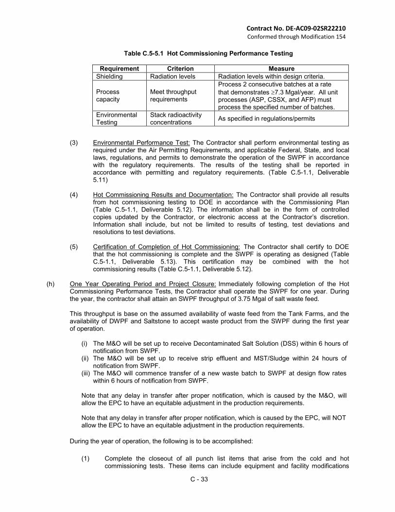
C - 33
Contract No. DE-AC09-02SR22210 Conformed through Modification 154
Table C.5-5.1 Hot Commissioning Performance Testing
Requirement Criterion Measure
Shielding Radiation levels Radiation levels within design criteria.
Process capacity
Meet throughput requirements
Process 2 consecutive batches at a rate
that demonstrates 7.3 Mgal/year. All unit processes (ASP, CSSX, and AFP) must process the specified number of batches.
Environmental Testing
Stack radioactivity concentrations
As specified in regulations/permits
(3) Environmental Performance Test: The Contractor shall perform environmental testing as
required under the Air Permitting Requirements, and applicable Federal, State, and local laws, regulations, and permits to demonstrate the operation of the SWPF in accordance with the regulatory requirements. The results of the testing shall be reported in accordance with permitting and regulatory requirements. (Table C.5-1.1, Deliverable 5.11)
(4) Hot Commissioning Results and Documentation: The Contractor shall provide all results from hot commissioning testing to DOE in accordance with the Commissioning Plan (Table C.5-1.1, Deliverable 5.12). The information shall be in the form of controlled copies updated by the Contractor, or electronic access at the Contractor’s discretion. Information shall include, but not be limited to results of testing, test deviations and resolutions to test deviations.
(5) Certification of Completion of Hot Commissioning: The Contractor shall certify to DOE
that the hot commissioning is complete and the SWPF is operating as designed (Table C.5-1.1, Deliverable 5.13). This certification may be combined with the hot commissioning results (Table C.5-1.1, Deliverable 5.12).
(h) One Year Operating Period and Project Closure: Immediately following completion of the Hot Commissioning Performance Tests, the Contractor shall operate the SWPF for one year. During the year, the contractor shall attain an SWPF throughput of 3.75 Mgal of salt waste feed.
This throughput is base on the assumed availability of waste feed from the Tank Farms, and the availability of DWPF and Saltstone to accept waste product from the SWPF during the first year of operation.
(i) The M&O will be set up to receive Decontaminated Salt Solution (DSS) within 6 hours of notification from SWPF.
(ii) The M&O will be set up to receive strip effluent and MST/Sludge within 24 hours of notification from SWPF.
(iii) The M&O will commence transfer of a new waste batch to SWPF at design flow rates within 6 hours of notification from SWPF.
Note that any delay in transfer after proper notification, which is caused by the M&O, will allow the EPC to have an equitable adjustment in the production requirements.
Note that any delay in transfer after proper notification, which is caused by the EPC, will NOT allow the EPC to have an equitable adjustment in the production requirements.
During the year of operation, the following is to be accomplished:
(1) Complete the closeout of all punch list items that arise from the cold and hot
commissioning tests. These items can include equipment and facility modifications
C - 34
Contract No. DE-AC09-02SR22210 Conformed through Modification 154
and repairs, operations procedure revisions, replenishment of spare parts, etc. Exceptions will be identified for items determined to be outside the original EPC contract scope.
(2) Resolve any product quality issues for the Saltstone and DWPF feed products and/or secondary wastes generated during cold and hot commissioning.
(3) Perform any modifications to the environmental compliance and/or safety basis documentation as a result of the information obtained in the hot commissioning testing.
(4) Prepare the as-built design of the SWPF process and facility. (5) Prepare and submit the Project Closure Package (Table C.5-1.1, Deliverable 5.14A) (6) Update operations procedures to reflect lessons learned during commissioning. (7) Ensure all documents, records, and procedures are complete and accurate and
turned over to the future operations contractor. (i) Completion of Contract Workscope Requirements. Following the successful completion of the
hot commissioning testing followed by one full year of successful radioactive operations the Contractor shall complete, at a minimum, the following activities to ensure the effective and efficient transition of the SWPF to the long term operations contractor. (Note: successful radioactive operation is defined as processing HLW salt solution at the design through put and attainment producing decontaminated salt solution and DWPF feed within the WAC for those facilities). The Contract work scope is deemed complete, once these activities have been completed to the satisfaction of DOE, and the long term operations contractor has certified acceptable turnover of the facility (Table C.5-1.1, Deliverable 5.14B, Milestone M7).
For a period of time of at least six months in duration, the Contractor shall make available of appropriately knowledgeable and trained personnel to perform the following functions: (1) Respond to technical questions from the future operations contractor. (2) Provide technical advice on proposed repairs and modifications to the SWPF. (3) Assist in the resolution of all equipment warrantee issues. (4) Provide support to DOE in the conduct of internal and external technical reviews and
presentations. (5) Assure all operations, maintenance, engineering, licensing and purchasing activities are
transitioned to the future operations contractor. (6) Financially close the contract.
C - 35
Contract No. DE-AC09-02SR22210 Conformed through Modification 154
Standard 6: Reserved
Standard 7: Environment, Safety, Health and Quality
The purpose of this Standard is to: (1) define Contractor(s) responsibilities for conventional non- radiological worker safety and health; radiological, nuclear, and process safety; environmental protection; quality assurance; and (2) identify specific deliverables the Contractor shall submit to DOE.
DOE will act as the regulator of radiological, nuclear, and process safety. (a) The primary objectives of ESH&Q are to:
(1) Demonstrate compliance with established requirements; (2) Apply best commercial practices to provide conventional non-radiological WS&H protection;
radiological, nuclear, and process safety, and environmental protection; and (3) Implement a cost-effective program that integrates environmental protection, safety, quality
and health in all Contractor(s) activities.
Environmental protection, safety, quality, and health program activities and deliverables shall be integrated with all technical and regulatory aspects of the SWPF.
(b) The Contractor(s) shall integrate safety and environmental awareness into all activities, including those of subcontractors at all levels. Work shall be accomplished in a manner that achieves high levels of quality, protects the environment, the safety and health of workers and the public, and complies with all requirements. The Contractor(s) shall identify hazards, manage risks, identify and implement good management practices, and make continued improvements in ESH&Q performance.
(c) The Contractor(s) is responsible for providing safe and healthful working conditions for employees
and all other persons under the Contractor’s control who work in the general vicinity of the Contractor site, including subcontractors. The Contractor(s) shall develop and implement integrated programs for conventional non-radiological worker safety and health; radiological, nuclear, and process safety; and environmental protection. The SWPF must function as an integral part of the site’s HLW System. Products, documentation, processes, operational procedures and other deliverables developed under this contract must be able to be merged into the site M&O systems. Therefore, in developing the implementing procedures for the ISMS and QA requirements, the Contractor(s) must plan and provide for future integration of the project with the full spectrum of site systems (both physical and administrative). A process shall be implemented that ensures all components of the project will interface both physically and functionally with all other site systems. In meeting this requirement, the contractor(s) shall develop implementing procedures/documents based upon the SWPF Standard/Requirements Identification Document (S/RID). The SWPF S/RID, at the Functional Area Level, identifies DOE ESH&Q requirements set forth in applicable Federal, State, and local laws and regulation, DOE Rules, DOE Orders, and directives, relevant industry (consensus) codes and standards, international standards, established site safety practices, etc. The SWPF S/RID has been tested and approved by DOE for work at the site. The contractor, however, is to review the M&O and SWPF S/RID to ensure all requirements applicable to the contemplated work are addressed and appropriate. With DOE approval, requirements may be added or deleted as appropriate for the project. In developing its own system of implementing procedures/documents to ensure compliance with the SWPF S/RID, the contractor at its own discretion, may either: (a) totally adopt the existing Site M&O procedures, including revisions as issued, as its own corporate procedures; (b) utilize some or all of its existing corporate procedures and adapt or create new corporate procedures/documents as needed to meet requirements; or (c) merge applicable Site M&O implementing procedures with its own existing, adapted or new corporate procedures/documents. The SMS must provide for linkage of implementing procedures/ documents to the S/RID requirements, and for maintaining configuration control whenever changes are made in the ISMS. The crosswalk between the contractor(s)
Contract No. DE-AC09-02SR22210 Conformed through Modification 145
C-36
program and the S/RID shall be documented in a S/RID Compliance document developed for DOE approval (Table C.5-1.1, Deliverable 7.1).
An ISMS meeting the requirements of DOE Policy 450.4, Safety Management System Policy shall be developed and implemented. The contractor shall prepare a description of their ISMS for DOE review and comment (Table C5.1-1, Deliverable 7.2). Implementation of the ISMS shall be conducted in phases and with verification of implementation included in the Project Baseline Schedule.
(d) The Contractor(s) shall identify all necessary permits, licenses and other regulatory approvals and
authorizations for the design, construction, commissioning and operation of the SWPF, unless otherwise identified in this Contract. The Contractor(s) in conjunction with the Site M&O contractor shall develop the necessary permit applications, license applications, requests for other regulatory authorizations, and supporting materials and documentation. The Contractor shall provide all technical and regulatory information and documentation and support to ensure that permits, licenses, and other regulatory authorizations and approvals are obtained in a timely manner to support the design, construction, commissioning, and operation of the SWPF.
(e) The Contractor shall implement a program to track and address environmental compliance issues and implement and comply with all requirements (including, but not limited to, permitting, environmental reports, enforcement actions, consent decrees, milestones/reports/management commitments, NEPA, pollution prevention, and waste minimization).
(f) The Contractor(s) shall work with the Site M&O contractor in providing legally and regulatory
required air and liquid effluent and near facility environmental monitoring. The Contractor shall collect, compile, and/or integrate air and liquid effluent monitoring data from operations and activities under their control. The Contractor shall compare the monitoring data with regulatory and/or permit standards applicable to their activities and/or operations and provide the data and analyses to the Site M&O contractor for use in preparing the mandatory State and Federal environmental reports for the Site in a timely manner. In addition, the Contractor shall provide appropriate environmental data for the SWPF to support Site assessments and preparation of the Site Environmental Report.
(g) The Contractor shall prepare and submit to DOE for review and action the following environmental
protection deliverables. The deliverables shall be consistent with the design and schedule for construction and commissioning the SWPF. Identification of the following deliverables does not modify or affect the Contractor’s responsibilities for environmental permitting, compliance, and protection identified in the Contract or as required under applicable law or regulation. The Contractor shall have the responsibility to identify and develop any necessary modifications to existing permit applications, license applications, requests for regulatory authorizations/approvals and supporting materials to support the design, construction, commissioning, and operation of the SWPF.
(1) Environmental Plan: The Contractor shall develop a detailed plan that identifies the
Contractor’s structured approach for environmental protection, compliance, and permitting, including: (i) Planned environmental permitting and compliance activities for design, construction,
testing, and commissioning the SWPF; (ii) Detailed permitting and compliance schedule integrated and linked to the technical
baseline; and (iii) Environmental monitoring and reporting requirements.
The Environmental Plan (Table C.5-1.1, Deliverable 7.3) shall be submitted for DOE review and approval, and include identification of where and when DOE or Site M&O Contractor action is anticipated or required. The Plan shall be submitted within three months after contract award. The Plan shall be updated as significant changes to the permitting schedules warrant.
(2) Reserved
Contract No. DE-AC09-02SR22210 Conformed through Modification 145
C-37
(3) Reserved
(h) Contractor shall implement NQA-1-2004 as follows: Parsons is to implement all 18 sections of Part I
and Subpart 2.7 from Part II of NQA-1-2004. Parsons shall maintain its ISO 9001 Program, utilizing the two quality standards to fully meet the requirements of DOE O 414.1C. Parsons shall give consideration to the guidance and positions included in NQA-1-2004 Parts II, III, and IV, in developing the instructions, procedures, and drawings for implementation of the SWPF QA Plan. However, with the exception of Subpart 2.7, Parts II, III, and IV are not requirements.
Standard 8: Safeguards and Security (S&S)
The purpose of this Standard is to describe the S&S requirements relevant to the SWPF construction and operations. (a) The Contractor shall in conjunction with the Site M&O Contractor develop and implement an S&S
Program to ensure the protection of DOE-owned material and information. The S&S Program shall ensure the protection of DOE-owned property, material, and information per the requirements of DOE O 470.4, Safeguards and Security Program, and all manuals applicable to this order. The Contractor’s S&S Program shall also ensure compliance with the following requirements as applicable: DOE O 205.1, Department of Energy Cyber Security Management Program; DOE O 471.1A, Identification and Control of Unclassified Controlled Nuclear Information; DOE O 471.3, Identifying and Protecting Official Use Only Information; DOE O 241.1A, Scientific and Technical Information Management. (1) The scope of DOE S&S requirements includes:
(i) Physical protection; (ii) Nuclear material control and accountability, if found applicable throughout the period of
the contract; (iii) Information and personnel security and the Site access requirements; and (iv) Government property protection.
(2) The Contractor shall design the SWPF in a manner to provide adequate response time for
SRS Protective Force and Emergency Response Personnel.
(3) The Contractor shall develop an S&S Plan for DOE approval (Table C 5-1.1 deliverable 8.1) that meets all requirements to construct and operate a facility at SRS. The Contractor shall also ensure the S&S Plan requirements are flowed down to subcontractors.
(b) The Contractor shall ensure the S&S Program implements the necessary requirements for gaining
access to SRS for project personnel and required equipment and material. The S&S requirements for gaining access to SRS are contained within DOE O 470.4, but are more specifically detailed in the Westinghouse Savannah River Company (WSRC) 7Q, Security Manual. For individuals requiring access to SRS, the contractor shall ensure the S&S Program implements the requirements specified within Homeland Security Presidential Directive #12, as promulgated in DOE Notice 206.3, Personal Identify Verification. The Contractor must adhere to the applicable procedures found in the 7Q Manual, but may opt to develop its own security manual (or procedure[s]) that implements site security similar to those found in the 7Q Manual. Should the Contractor wish to develop its own security manual or procedure(s), then such manual/procedures shall be submitted to DOE for approval.
(c) For obtaining visitor access to SRS, the Contractor shall implement the site’s Point-of-Entry Program, as delineated within the WSRC 7Q Manual and WSRC 8Q Manual Procedure 15, Workplace Safety and Health Program for SRS Visitors, Vendors, and WSRC/BSRI Subcontracts. Should the Contractor wish to develop its own procedure for implementing Point-of-Entry Program requirements, then such procedure shall be submitted to DOE for approval.
(d) All vendor deliveries are required to enter and exit SRS using Barricade #2, also known as the Aiken Barricade, located at the junction of Highway 19 and SRS Road #2. All delivery vehicles are subject to inspection by SRS Protective Force personnel, and are typically not allowed to pass through the barricade until 0730 hours on weekdays. All delivery vehicles must also be escorted by an authorized, properly cleared Contractor employee to and from the barricade; unless the driver of the vehicle possesses and SRS photo-badge.
Contract No. DE-AC09-02SR22210 Conformed through Modification 145
C-38
(e) DOE-SR reserves the authority and right to modify the requirements for employee, visitor, and delivery personnel access to the SRS based upon any change in the Site Security Condition as required by any change in the Homeland Security Advisory System Threat Level. Any impacts to the Project as a result of changes to threat level will be the subject of an Equitable Adjustment under the changes clause of this Contract.
C.7 FACILITY SPECIFICATION
The facility specifications provided in this section are provided to guide the planning and design of the SWPF. These specifications are not mandatory, however, any exceptions to their use must be authorized by written approval of the COR. Contractor shall submit written justification to COR to obtain COR approval.
1.0 Operating Capacity. To process the entire HLW inventory a facility starting operations in 2010
would require an annual throughput of nominally 6 million gallons. A complete analysis of facility through put to meet process objectives is contained in the Bases, Assumptions, and Results (BAR) report, WSRC-RP-99-00006, Rev 3 available on the SWPF web page (password protected). Sizing for the initial SWPF should be scaled off of this design data for the full-scale facility.
2.0 Interface with Site Systems Facilities Equipment Procedures and Requirements. The Facility
shall be designed for integrated long-term operations with existing site infrastructure. Efforts should be taken to ensure compatibility with site wide calibration, maintenance, and testing equipment, facilities, procedures, and requirements.
3.0 Design Conditions, Constraints, Codes and Standards. The Contractor shall develop a database
of National Consensus Code and Standards to be used in the design of the SWPF. This Database will be the code of record for the SWPF and will be approved by DOE early in the Conceptual Design process. To assist in development of the code of record a preliminary listing of National Consensus Codes and Standards is provided. In addition, the SRS Engineering Standards listed in Section 3.25 are used to supplement the Code of record with specific SRS requirements. The contractor shall use this information and establish a code of record for the SWPF that provides the best value for the government while meeting safety, operational, maintenance, and environmental requirements. Areas that deviate from the codes and standards described below shall be highlighted when submitted to DOE for approval. Rational for the deviations shall also be provided.
3.1 Process Materials 3.1.1 Provisions in the facility design shall be provided to prevent inadvertent transfer of incoming
waste streams to SWPF.
3.1.2 Process vessels shall be compatible with the process chemistry and shall have a minimum 10 year design life for remotable vessels. Permanently installed vessels shall be designed for the life of the facility.
3.1.3 Storage tanks shall be constructed of materials compatible with the stored fluids.
3.1.4 Equipment and materials (such as gaskets, cables, etc.) shall be radiation-resistant and
chemical resistant as to provide the intended service in the operating environment for the design life.
3.1.5 The facility shall be designed to limit generation and dispersion of radioactive and hazardous
material by providing designs to minimize generation and promote segregation of waste in accordance with DOE O 435.1, Radioactive Waste Management.
3.1.6 Materials in radiation areas will be capable of withstanding the total absorbed dose over the
life of the system, or it will be designed to be replaced. The use of Teflon in areas which average 200 mR/hour or below (radiation rate calculated assuming feed is at the maximumwaste acceptance criteria limit) is allowed. Also, the use of Teflon in areas with average radiation fields above 200mR/hour (calculated at maximum waste acceptance
Contract No. DE-AC09-02SR22210 Conformed through Modification 145
C-39
criteria limit) may be allowed, but will require written approval from DOE on a case-by-case basis via inclusion in the Basis of Design/Design Criteria Database (Table C.5-1.1, Deliverable 3.3). The basis of Design/Design Criteria Database will identify all radiological areas where Teflon is allowed for use.
3.2 Environmental Constraints 3.2.1 Design for in-ground waste transfer lines shall provide a secondary containment and systems
to monitor, detect, and collect any leakage from in-ground waste transfer lines and in-ground radioactive waste handling and storage tanks.
3.2.2 Containment areas and or dikes capable of containing the largest tank volume, plus a margin shall be provided around bulk chemical storage tanks, containing compatible liquids.
3.2.3 Means to monitor airborne effluents from SWPF during normal operations shall be provided as
specified by environmental regulations and permits.
3.3 Health Protection
3.3.1 Monitoring equipment shall provide means for calibration to appropriate standards. Alarm and
warning systems that are required to function during a loss of power shall be provided with a Uninterrupted Power Supply unless demonstrated that the system can tolerate a temporary loss of power without loss of data, and they are provided with standby power. Determination of the power supply type and quantity shall be based on the safety classification of the monitoring system or device.
3.3.2 Area radiation monitors shall be installed in frequently occupied areas with the potential for unexpected increase in dose rates and where there is a need for local indication of dose rate prior to personnel entry. Monitors shall have local audio-visual alarms and remote alarms in the Central Control Room.
3.3.3 Confinement barriers and associated ventilation systems, shall maintain a controlled,
continuous airflow from the environment to the building and from non-contaminated areas of the building to potentially contaminated areas, to the normally contaminated areas and finally through High-Efficiency Particulate Air (HEPA) filters prior to release to the environment.
3.3.4 Entry points into Radiological Buffer Areas (RBAs) shall be minimized. Within the RBA, entry controls shall be established for radiological areas. The design of the facility shall include controlled access to areas of potential hazards within the facility. Personnel entry control shall be established for each radiological area. The degree of control shall be commensurate with existing and potential radiological hazards.
3.3.6 System alignments, which include flow path and inadvertent flow path, shall be verifiable
without requiring personnel entry into radiological areas.
3.3.7 Remote handling equipment shall be considered where it is anticipated that exposure would approach dose limits or where there is a potential for dose from puncture wounds.
3.3.8 Shielding may be designed using any applicable method. The designer shall be aware of the
limitations of the method employed per American National Standards Institute (ANSI)/American Nuclear Society (ANS)-6.4. The selection of shielding materials shall be such that calculation results are conservative. Reflection configurations shall be reviewed to determine the effect on the design radiation levels. Selection of shielding material shall consider minimization of hazardous materials and/or the encasing of materials to preclude the generation of mixed waste.
3.3.9 Special features shall be considered for access through confinement barriers to minimize the
impact of facility access requirements on the ventilation system and to prevent the release of airborne radioactive materials.
3.3.10 Spill prevention and control shall be considered in the design stage of the facility to minimize
the possibility of accidentally releasing hazardous waste to the environment.
Contract No. DE-AC09-02SR22210 Conformed through Modification 145
C-40
3.3.11 The design of the facility and the selection of materials shall include features that facilitate
operations, maintenance, decontamination and decommissioning. 3.3.12 This facility shall comply with the requirements of 10 CFR 835.
Table 3.3-1 - Radiation Zoning Criteria
RESERVED 3.3.13 The design shall provide for monitoring of occupational workers in work areas where
radioactive materials are stored and handled. The use of devices to warn personnel of possible contamination or other hazards shall be evaluated and provided. Whole body personnel contamination monitors shall be provided at the exit from RBAs to prevent the spread of contamination. The background radiation dose rate at the personnel contamination monitors must be designed to meet the specifications of the unit.
3.3.14 The facility design shall provide for the minimization and segregation of radioactive, hazardous, and mixed wastes into compatible groups for the treatment, storage, and disposal of such wastes.
3.3.15 The Central Control Room (CCR) shall have the capability to read all remotely instrumented
radiological monitoring equipment. 3.3.16 Warning and alarm systems shall be designed, installed and tested to ensure that they are
heard in the ambient condition of the area they cover. Safety alarm systems, such as evacuation alarms, shall enunciate inside and outside the monitored area to identify hazardous condition to anyone inside or outside in the vicinity of the monitored area. The use of visual as well as audible alarms shall be evaluated. Safety alarms in high noise areas shall be provided with audible and visual alarm systems.
3.4 Operating Conditions
3.4.1 Tanks that contain or have the potential for developing flammable or explosive mixtures shall
be provided with suitable safety systems to mitigate the potential for fire or explosion.
3.4.2 All tanks that contain organic waste shall be assessed for flammability and be provided with suitable safety controls to mitigate any hazards.
3.4.3 The cross-flow filters shall be designed for backpulsing to optimize filter operation.
3.4.4 The cross-flow filters shall be designed for dynamic cleaning using recirculating streams of
oxalic acid and caustic. 3.4.5 The facility design shall permit the cross-flow filters to be placed in a wet lay-up using a dilute
sodium hydroxide solution. 3.4.6 Two separate level indications per tank shall be provided to support inter-area transfers.
3.5 Industrial Safety 3.5.1 Engineered safety features shall be the primary method used to minimize exposure to
carcinogens and to prevent the release of carcinogens into the work environment.
3.5.2 Asbestos, asbestos-containing materials or materials containing refractory ceramic fibers shall not be used at SWPF.
3.5.3 SWPF design shall comply with the safety requirements of 10 CFR 851, Energy: Department
of Energy: Worker Safety and Health Program.
3.6 Waste Management
Design shall comply with the requirements of DOE O 435.1, Radioactive Waste Management by providing for waste minimization and volume reduction of radioactive liquid wastes, reducing liquid usage and maximizing recycling activities.
Contract No. DE-AC09-02SR22210 Conformed through Modification 145
C-41
3.7 Civil and Sitework
3.7.1 The SWPF design shall include provisions for erosion control and soil stabilization in ditches,
fill, slopes, embankments, and denuded areas, and restoration of areas disturbed by the project to original or improved conditions.
3.7.2 Facility safeguards monitoring or detection devices shall be protected during operation by the use of soil erosion controls to ensure continued operation.
3.7.3 Positive stormwater drainage shall be provided to prevent standing water within the facility
area. 3.7.4 SWPF shall be designed to connect with the existing SRS transportation infrastructure. 3.7.6 Where practical, roads, sidewalks and parking areas shall be constructed with porous paving
materials.
3.7.7 RESERVED 3.7.8 Breathing air (permanent or portable) shall be provided to protect workers from airborne
contamination as required. 3.7.9 RESERVED
3.7.10 Sources of compressed air shall be provided for Instrument Air and Plant Air in SWPF. A
minimum of 25% excess capacity shall be built into these systems to accommodate future users.
3.7.11 There shall be no interconnections among stormwater systems, the sanitary waste system and
radioactive or other hazardous material handling systems. 3.7.12 There shall be no interconnections between the potable water system, the sanitary waste
system, and process systems. 3.8 Structural
3.8.1 Structures, systems and components shall be designed for Natural Phenomenal Hazards
commensurate with their performance category. Performance categories shall be developed and applied in accordance with DOE Guide 420.1-2, DOE-Standard (STD)-1021 and DOE- STD-1020.
3.8.2 Structural analysis of piping shall be based on the end of life minimum wall (corroded)
condition. 3.8.3 Penetration configurations in concrete shield walls shall be shown to provide adequate
attenuation of radiation. 3.8.4 Concrete structures shall be designed to prevent acidic degradation.
3.8.5 Embedded process piping shall be designed for the life of the facility. Welds in embedded
process piping shall be subject to 100% volumetric radiographic examination, except that welds in embedded process drain piping shall be subject to a minimum of 5% radiographic and 100% visual examination. Process piping in this context refers to piping in the process area of the facility.
3.8.6 A minimum of 20% spare embedded penetrations shall be provided.
3.9 Architectural
Contract No. DE-AC09-02SR22210 Conformed through Modification 145
C-42
3.9.1 The facility layout shall provide separation of administrative and support personnel from operations and process activities. Facility layout shall be based on segregation of facility functional areas. The first level of segregation should separate process areas from non- process areas. Within process areas, rooms that have no radioactive material should be separated from rooms that contain radioactive material.
3.9.2 The facility shall contain or make necessary arrangements for:
Areas for radiological support functions; specifically, for a Radiological Control Office, personnel decontamination, instrument storage and decontamination.
Shops to support maintenance and electronics and instrumental shop work and tool/ measuring and test equipment storage/issue.
A classroom at the facility's simulator for training of operations personnel.
Facilities for storage of contaminated equipment, which are accessible to allow decontamination, maintenance, repair or disposal operations to proceed when required.
An area(s) for the storage and staging of clean equipment.
A storage and unloading area for compressed gases (portable cylinders).
Floor space/wall space for status boards and manning of a facility emergency operations center.
Warehouse facility sized to suit the facility needs determined by the design.
3.9.3 RESERVED
3.9.4 Design shall ensure maintenance facilities, equipment and tools are capable of being
maintained and are strategically located so that maintenance activities are effectively accomplished.
3.9.5 A mechanical equipment test control station will be provided to run-in and test repaired equipment.
3.10 Mechanical
General
3.10.1 The SWPF design life shall be 40 years.
3.10.2 Mechanical components located in high contamination potential areas shall be evaluated and if necessary shall be designed with a surface finish to facilitate decontamination.
3.10.3 Components (piping, storage tanks and instrumentation) susceptible to freezing shall be
provided with freeze protection.
Thermal Insulation
3.10.4 Mechanical insulation shall be provided except in Zone 1 process/tank cells and other areas with a high potential for radiological contamination to minimize energy losses or gains, prevent condensation or freezing, reduce heat loads in areas requiring controlled temperatures, and provide for safe surface temperatures for piping and piping components.
3.10.5 Thermal insulation shall be non-combustible or fire resistant.
Vibration
3.10.6 Piping shall be supported/restrained to avoid vibration resulting from the flow of service medium. Transient loads under all modes of operation shall be considered in the design of the supports.
3.10.7 Equipment supports subjected to vibration shall be designed to avoid resonance between the operating frequency and the natural frequency of the equipment on its support.
Pressure
3.10.8 Pressure relief devices shall be vented to environmentally acceptable locations such as off- gas systems or evacuated relief tanks.
Contract No. DE-AC09-02SR22210 Conformed through Modification 145
C-43
3.10.9 Pressure protection methods that use active systems shall be equipped to conduct periodic testing.
3.10.10 The outdoor relief valve discharge vent piping shall have design features to prevent the
accumulation of water.
3.10.11 Systems that must remain in operation to support day-to-day operation shall be designed to accommodate periodic testing.
Piping
3.10.12 Underground or embedded waste transfer piping shall be provided with cathodic protection or other suitable corrosion protection measures.
3.10.13 Test capability shall be provided for all removable process piping including process jumpers.
3.10.14 Where jumpers are required, connectors should be standardized. Hanford type or similar proven connectors at comparable US facilities should be used.
3.10.15 Gaseous and liquid piping systems shall include physical design features to prevent damage from “hydraulic” transients due to liquid and gas hammer and shall be designed to eliminate accumulation of condensate.
3.10.16 Piping runs under positive pressure shall have capability for venting, draining and refilling.
Valves
3.10.17 Inside the Process Building, valves shall include leakage minimization features.
3.10.18 Stop valves shall be provided to isolate equipment, or appurtenances for ease of maintenance.
3.10.19 Process cell valves shall be capable of being operated remotely.
3.10.20 All isolation valves shall be designed to be lockable or with the capability to be locked.
Pumps
3.10.21 Continuous operation pumps that are critical to the salt treatment process shall be provided with installed back-up capability to allow removal for maintenance and to minimize process interruption.
3.10.22 Pumps shall be designed for low shear application where required by service application.
Tanks
3.10.23 Process tanks shall be equipped with internal spray nozzles to facilitate decontamination.
3.10.24 Process tanks shall be properly grounded to prevent potential ignition source from static charges.
Cranes
3.10.25 The Cranes shall not have dual drive axles.
3.10.26 Remote operation of overhead crane should be used, where practical.
3.10.27 Where cell cover blocks are utilized, an overhead crane shall be provided to support cell cover/removal and equipment installation and removal. The overhead crane should consider remote control by a radio frequency control system and shall have a remote retrieval system.
3.10.28 A color television camera shall be provided for process cell inspection. The camera shall be controlled remotely and will have pan, tilt and zoom capabilities.
Contract No. DE-AC09-02SR22210 Conformed through Modification 145
C-44
HVAC 3.11.2 The location of air supply intakes shall be designed to avoid the possibility of drawing in fumes
from diesel generator exhaust or from cold feed tanks.
3.11.3 Provisions shall be made to ensure that hazardous levels of contaminated air are not released into adjacent work areas or the outside environment.
3.11.4 The ventilation airflows shall be from zones of lower contamination potential toward zones of
higher contamination potential using differential pressure to control the direction of airflow between rooms, corridors and zones in the facility. Air recirculation from a zone of higher contamination back to a zone of lesser contamination shall be prohibited.
3.12 Fire Protection
The Fire Protection program will be developed commensurate with the development of the facility design. The PHA will identify major fire protection features that must be included in the project to satisfy the various code requirements.
3.13 Process or Production Requirements
3.13.1 Process Tanks and inaccessible tanks shall be instrumented such that loops and sensors can
maintained, calibrated, and replaced without requiring entry into process areas consistent with the access restrictions specified in 10 CFR 835.
3.13.2 The design and installation of in-cell tanks <30,000 gallons and equipment shall allow for remote removal and replacement, except in instances where equipment is designed to operate continuously without the need for major repair or replacement over the design life of the plant.
3.14 Electrical
Non-fiber optic signal cables shall not be run in close proximity to power cables or other cables that could induce voltages into the signal cables.
3.15 Grounding
3.15.1 Lightning dissipation meeting the requirements of National Fire Protection Association (NFPA)
780 for a Franklin Air Terminal System shall be provided.
3.15.2 Uninterruptible power shall be provided for equipment that is required to operate continuously and cannot sustain functions through the momentary power loss that occurs when a standby power source comes on line and picks up the load following a loss of normal power.
3.15.3 If applicable, safety class standby power shall meet the redundancy and seismic requirements of the safety class system(s) that it is supporting.
Contract No. DE-AC09-02SR22210 Conformed through Modification 154
C-45
Instrumentation 3.15.4 Instrumentation shall be designed to monitor process variables and systems over their
defined ranges for normal operation with the appropriate level of accuracy and repeatability, anticipated operational occurrences and accident conditions as appropriate to ensure adequate safety.
3.15.5 Instrumentation shall be selected to be compatible with the process conditions at its installed location.
3.15.6 Instrumentation shall be selected with environmental ratings which envelope the design
conditions expected at their installed locations for the operating modes, which they are required to support.
3.15.7 Instrumentation/controls and valves shall go to a safe state on loss of power or motive force.
3.16.6 Valves that are controlled remotely and valves within shielded cells shall be provided
with means to indicate, (e.g., limit switches), whether the valve is fully open or fully closed. 3.16.7 Instrumentation shall be designed and installed to provide accessibility for
maintenance, calibration, periodic online surveillance testing and troubleshooting. 3.16.8 Instrumentation shall be located outside of shielded cells where possible.
Instrumentation that must be located inside a shielded cell shall be designed to allow remote maintenance and operations. Where access to instrumentation inside a shielded cell prohibits remote maintenance, redundant or alternative instrumentation shall be installed.
3.17 Control Systems
3.17.1 SWPF shall be configured is such a way as to provide the capability for a safe and
orderly emergency shutdown of the facility processing operations.
3.17.2 SWPF emergency shutdown process must support the capability to successfully accomplish the operation by supporting manually activated automated shutdown sequences, manual single point emergency stop of all critical safety related equipment, and Emergency Operating Procedure execution by local control operators.
3.17.3 The design of the Human-Machine Interface for operations and control of the SWPF
(Control Rooms and Local Control Station environments) shall incorporate human factors, engineering principles and operating experience to promote safety and high operational reliability. The design should incorporate the appropriate instrumentation and controls to provide the operators with diagnostic and mitigation capability.
3.17.4 The process shall be operated from a central location through a Distributed Control
System (DCS), which shall integrate operation of the facility processes and Infrastructure where appropriate.
3.17.5 The Facility shall provide a CCR arranged in such a way that it is conducive to complying
with Conduct of Operations requirements for the DCS. 3.17.6 Requesting transfer of fresh waste from the Tank Farm shall be performed from within
the SWPF CCR and shall be capable of providing immediate and direct notification to the Tank Farm operator to initiate or secure the transfer.
Contract No. DE-AC09-02SR22210 Conformed through Modification 154
C-46
3.17.8 Design shall provide protection such that failure of any component in the control system shall not jeopardize the integrity of the plant systems.
3.17.9 The DCS shall be constructed and arranged in such a way as to provide for regular
maintenance. 3.17.10 Controlled levels of access to the DCS equipment and operating system shall be
maintained throughout the facility. Controls shall include a network firewall to protect against unauthorized access to the process computing devices.
3.17.11 Project shall provide for a development control system identical to the primary
process control system. This development system shall be isolated from the process system, and used for software development, testing, verification, and demonstrations in an off-line capacity prior to software being installed into the facility. This development system shall be equipped with input/output racks that will be used to test and/or troubleshoot control system hardware prior to field installation.
3.17.12 Video and audio systems shall be provided to support remote operations within the Facility.
3.17.13 The Facility shall provide sufficient space for control system Input/Output cabinets that
have 20% spare capacity.
3.17.14 Design should consider a dedicated, redundant fiber optic network for the Control system.
3.17.15 Systems that interface with the DCS (local control stations, manufacturing and
engineering systems, etc.) shall have common network wiring, components, connections, and communication protocols throughout the Process Building as well as any remote locations.
3.17.16 The facility shall be provided with a Backup Control Room if the CCR design does not withstand a design basis accident(s).
3.17.17 The facility shall have the ability to distribute information among personnel electronically.
3.17.18 Design shall provide the capability to monitor and/or trend equipment performance.
3.18 Communication
3.18.1 Telephone, video, public address and computer communication systems shall be
installed and shall be connected to the existing SRS communication systems.
3.18.2 A backup communication system shall be provided that does not rely on normal or emergency power for communication with the control-room operator.
3.18.3 Communication systems shall not interfere with or be interfered with by process equipment.
3.19 Safeguards and Security
3.19.1 Preliminary Vulnerability Assessment planning indicates Property Protection Area
controls will be required. This assumption must be confirmed via the final Vulnerability Assessment.
3.19.2 Equipment lay down areas shall be protected by temporary barriers to impede access during facility construction.
Contract No. DE-AC09-02SR22210 Conformed through Modification 154
C-47
3.19.3 Access points to the Administration and Miscellaneous Buildings shall be equipped with key type locks of access cards.
3.19.4 An electronic personnel accountability system shall be provided.
3.20 Permits
3.20.1 The SWPF shall meet the requirements of all applicable Local, State and Federal Permits.
3.20.2 A Power Service Utilization Permit shall be obtained during Conceptual Design.
3.21 Maintenance
3.21.1 The process area design shall provide for the removal, replacement, and maintenance of components.
3.21.2 The SWPF shall provide the following capabilities:
Laydown Area to accommodate the staging of equipment during removal and installation.
Where appropriate, process systems and cells shall be capable of being remotely flushed and/or decontaminated to accommodate maintenance activities.
Contact Decontamination and Maintenance to accommodate thecontact decontamination and subsequent maintenance of equipment.
Laydown, Decontamination and Maintenance capabilities shall be sufficient to accommodate the largest remotable cell component.
3.21.3 Design shall provide an appropriate storage location at the facility for critical spare items.
3.21.4 The capability shall be provided to unload/load contaminated and clean equipment for shipment including the ability to handle, package and survey within a contamination area.
3.21.5 Stands, jigs and hoists to handle transport and repair equipment shall be provided.
3.21.6 Location, tools and equipment shall be provided to repair and clean contaminated
equipment.
3.21.7 Design shall provide single point power source isolation for instruments and equipment whenever possible. Equipment isolation points shall be capable of accepting a lock.
3.21.8 Design shall incorporate the maximum use of installed test connections, jacks and plugs.
3.21.9 Systems shall be designed to allow testing at the component, system and integrated
system level.
3.21.10 Where practical, repaired equipment should be tested in the workshop areas before returning the equipment into service.
3.21.11 The maintenance organization shall be provided an appropriately designed and
configured off-line control system for troubleshooting and running repaired equipment.
3.21.12 Equipment shall have access panels where replacement of parts is necessary.
3.21.13 Design shall incorporate drain and flush capability for process vessels/piping to support line break operation.
Contract No. DE-AC09-02SR22210 Conformed through Modification 154
C-48
3.21.14 Reserved
3.21.15 Component isolation for removal of parallel instrumentation loops for critical systems
shall have independent isolation. 3.21.16 Process system piping and instrumentation shall use the same configuration for the
same functions to minimize maintenance and operation interface problems. 3.21.17 Designs for maintenance and in-service inspections within the process area shall not
adversely affect operations.
3.21.18 The facility design shall provide for inspections of safety-related equipment.
3.21.19 Provisions shall be incorporated into the design of the facility for the repair and replacement of materials handling equipment.
3.21.20 Provisions shall be incorporated into the design of the facility for the repair and
replacement of major processing system components/equipment. 3.21.21 Where in-place handling is not practical, the design shall include maintenance or
inspection facilities and carrier systems to transport components to and from the facilities. 3.21.22 Where radiation or other hazards create an undue risk to personnel and preclude
contact inspection, the project shall provide for component removal and replacement by remote handling equipment.
3.21.23 Process systems and components, especially those performing safety-related functions,
shall be designed and arranged so that they can be adequately inspected, tested and maintained as appropriate before being placed in service, and at suitable and regular intervals thereafter.
3.21.24 A list of spare parts necessary for routine operation and maintenance of equipment shall
be provided. 3.21.25 Equipment shall be located a sufficient distance from stationary structures so that access
is afforded for operation, inspection, and maintenance of equipment without the need to routinely remove additional structures or equipment.
3.21.26 Equipment located within gloveboxes shall be accessible for operation, inspection and
planned maintenance without breaching glovebox integrity. 3.21.27 Safety-related systems shall be designed to allow for calibration of the
instruments/equipment through redundant systems, or installation of isolation/test valves to calibrate in place.
3.21.28 The decontamination cells shall have service connections pre-plumbed/wired.
3.22 Manufacturing and Engineering Systems
3.22.1 Design shall provide for collection, history, and trending of process data.
3.22.2 Design shall provide for automated collection of equipment data including specifications
and status. 3.22.3 Design shall provide for data collected from laboratory procedures.
Contract No. DE-AC09-02SR22210 Conformed through Modification 154
C-49
3.22.4 Design shall provide for management of data on chemical materials contained within
the facility (e.g., process chemicals such as caustic; industrial chemicals such as oxalic acid, chemical inhibitors; and miscellaneous chemicals such as floor cleaners, oils) and shall have inventory, physical, chemical toxicological, and health information data available.
3.22.5 Design shall comply with Human Factors Engineering practices in design of electronic
application user interfaces and local computing environments within the facility. 3.22.6 Controlled levels of access to the Manufacturing and Engineering System equipment
and software systems shall be maintained throughout the facility. 3.22.7 Design shall integrate process, operations, maintenance and business applications
where appropriate. 3.22.8 Design shall provide standards for use in development of electronic applications.
3.23 Remotability
3.23.1 Process Cell jumpers shall be designed to minimize crossing over other jumpers.
Jumper arrangement shall be based on failure rates of equipment, maintenance frequencies and safety functions providing the optimum arrangement to minimize the number of jumpers removed, the frequency of removal and the potential for entering into Limited Conditions of Operations during jumper manipulation.
3.23.2 For all equipment not designed for the life of the facility, stacking of process vessels shall be avoided and overhead access shall be provided.
3.23.3 Jumpers shall be balanced to suit their installation application (usually balanced vertically)
by the addition of stainless steel encased counterweights.
3.23.4 RESERVED
3.23.5 Electrical and instrumentation jumpers shall use SRS standard pin connections with upper and lower holder assemblies.
3.23.6 Acme studs should be considered to assemble and disassemble equipment remotely.
When using Acme studs on equipment that will not permit the shank of the impact wrench to clear in the vertical direction, a dutchman should be installed. When rotation of the impact wrench must be limited to prevent damage to nearby equipment, lugs should be welded to the flange to restrict the movement of the wrench or a dutchman used.
3.23.7 Standard SRS style nozzles and jumpers shall be considered where jumpers are required.
3.23.8 Standard locating dowels shall be utilized in the assembly and disassembly of
remotable equipment.
3.23.9 The construction and installation tolerances for remotable equipment shall support full remotability and be demonstrated.
3.23.10 Lifting beams should be standardized, where practical for equipment requiring remote
removal for maintenance.
Contract No. DE-AC09-02SR22210 Conformed through Modification 154
C-50
3.23.11 All remotable tanks, vessels and specialized equipment shall be lifted and balanced after fabrication to allow them to remain in an upright condition during remote removal and installation.
3.23.12 Remotable equipment shall be provided with standard guides and lifting features (e.g.,
trunnions, bails) to enable remote removal and replacement.
3.24 Decontamination and Decommissioning
3.24.1 The design of the area in the facility that may be contaminated with radioactive or
other hazardous materials under normal or abnormal operating conditions shall incorporate measures to simplify future decontamination. Such items as service piping, conduits, and ductwork will be kept to minimum in these areas and will be arranged to facilitate decontamination.
3.24.2 The following design principles shall be considered:
Use of modular confinements for radioactive and hazardous materials to preclude contamination of the fixed portions of the structure.
Long runs of buried contaminated piping will be minimized to the extent possible given process system constraints, and provisions will be included in the design to ensure the integrity of joints in buried pipelines.
A remote operated cutting tool shall be provided to cut up jumpers and steel structures to facilitate dismantlement, removal, and packaging of contaminated equipment from the facility.
Use of modular shielding in interior areas to permit modifications to larger shielded areas for future use.
Use of lifting lugs on equipment.
The Decontamination Area shall be lined with stainless steel or other suitable coating to facilitate decon of the area to minimize exposure.
3.25 Code and Standards
The following is a preliminary listing of National Consensus Codes and Standards to be used in the design of the SWPF. The list is not to be considered all-inclusive. Additional Regulations, DOE Orders, codes and standards could become applicable throughout the project and shall be evaluated for application to this project. The most current document revision in effect at the time of the contract shall apply unless otherwise specified.
AASHTO ACI AWWA ANS ASHRAE CGA SDWA API SMACNA ASCE
ASME ASTM
10CFR435” CMAA IEEE
Contract No. DE-AC09-02SR22210 Conformed through Modification 154
C-51
10CFR835 IESNA 29CFR1910 ISA 29CFR1926 NACE” 40CFR125 NEMA 40CFR141” NFPA 40CFR142 NUREG 700 40CFR61 NUREG CR 6393 40CFR68 TEMA
TIA/EIA
The following SRS Standards shall be considered in the design of the
SWPF: 01060 SRS Structural Design Criteria 01065 Strong Motion Seismic Monitoring Instrumentation for SRS 01101 Use of Listed Equipment & Components for Safety Class Applications 01110 SRS Civil Site Design Criteria 01120 SRS Fire Protection Design Criteria 01703 Application of ISA S84-01 for SRS Non-Reactor Facilities (U) 01709 Color Conventions for Process Displays 05951 Corrosion Evaluation: Stainless Steels & Other Corrosion
Resisting Alloys 05952 Required Pract ices to Minimize Chloride Induced Stress
Corrosion Cracking of Type 300 Series Austenitic Stainless Steel 07270 Installation and Inspection of Penetration Seals 13096 Field Installation of Nuclear Incident Monitors 15060 ASME B31.3 Additional Requirements for SRS Piping Systems 15888 HEPA Filter Requirements 15889 Confinement Ventilation Systems Design Criteria 15980 Mechanical Installation of Safety Class & Safety
Significant Instrumentation 16050 SRS Electrical Design Criteria 16055 Telecommunications
C.8 BASELINE SPECIFICATION
Specifications for feeds to and products from the SWPF are subject to change based on the results from alternate salt processing initiatives. A Waste Feed Strategy and Product and Secondary Waste Specifications will be developed in conjunction with DOE and the M&O contractor as these variables are defined. A brief synopsis of tank waste characterization, Saltstone facility waste acceptance criteria, and DWPF feed data is provided to aid in proposal preparation only. This data is subject to change as a function the volume of waste that can potentially be processed by alternate methods and changes in permits and other requirements. Once these variables and the process capacity of the SWPF are better defined a strategy for waste removal, blending, and SWPF feeding can be developed.
Baseline Specification 1: Tank Waste Characterization Data Baseline Specification 2: Saltstone Facility Waste Acceptance Criteria Baseline Specification 3: High Activity Fraction Feed to the DWPF
Baseline Specification 1: Tank Waste Characterization Data
This information is available on the Salt Processing Project website. The website requires a password for access, which may be obtained by following the procedures contained in the Notice To Offerors in Section L on page 1.
Contract No. DE-AC09-02SR22210 Conformed through Modification 154
C-52
Baseline Specification 2: Decontaminated Salt Solution (DSS) Feed to the Saltstone Facility
The Saltstone Production Facility (SPF) has been permitted by the SCDHEC as a totally enclosed, industrial wastewater treatment plant. The SPF operating permit currently limits the processing rate of DSS in the SPF to 12 million gallons annually. The Saltstone Disposal Facility (SDF), located near the SPF, is also permitted by SCDHEC as an industrial waste landfill. Current permitted capacity of the SDF for disposal of saltstone is 174 disposal cells contained in large concrete vaults (14 12-cell vaults and 1 6- cell vault). Each cell has the capacity to contain the volume of saltstone generated from about 1.1 million gallons of salt solution, corresponding to a total disposal capacity for about 190 million gallons of salt solution. Current and projected future salt inventory will require disposal of 80 to 100 million gallons of salt solution. The DOE regulates solid Low Level Waste (LLW) disposal using long-term performance criteria [3] for near-surface disposal, as described in DOE O 435.1. Although the NRC does not regulate saltstone disposal, the NRC Class A LLW limits and landfill design and closure specifications for solid radioactive waste disposal are used as a guide to set limits for the DOE Authorization Basis (AB) and the SPF WAC for DSS transferred to the SPF.
The salt solution concentration limits for radioactive contaminants in the current SPF WAC are shown in Table 2-1. Decontaminated salt solution within these limits would yield saltstone that is well within the NRC Class A LLW disposal limits for radioactive contaminants in solid waste. The permit requires these concentrations to be monitored and reported if they differ significantly from the concentrations discussed in the permit, but the actual concentrations are not regulated by SCDHEC. Similar limits for chemical contaminants are shown in Table 2-2. Note that NaF is the only sodium salt for which a limit has been imposed in the SPF WAC because of potential impact on groundwater.
Saltstone is a solid waste form that is the product of chemical reactions between a salt solution and a blend of cementitious materials (slag, fly ash, and a lime source). An acceptable saltstone product can be produced over a broad range of these four components. Due to the heat of hydration
generated as the saltstone cures, salt solution temperature must be less than 45 oC when
processed in the SPF to assure acceptable physical properties and leach resistance of cured saltstone.
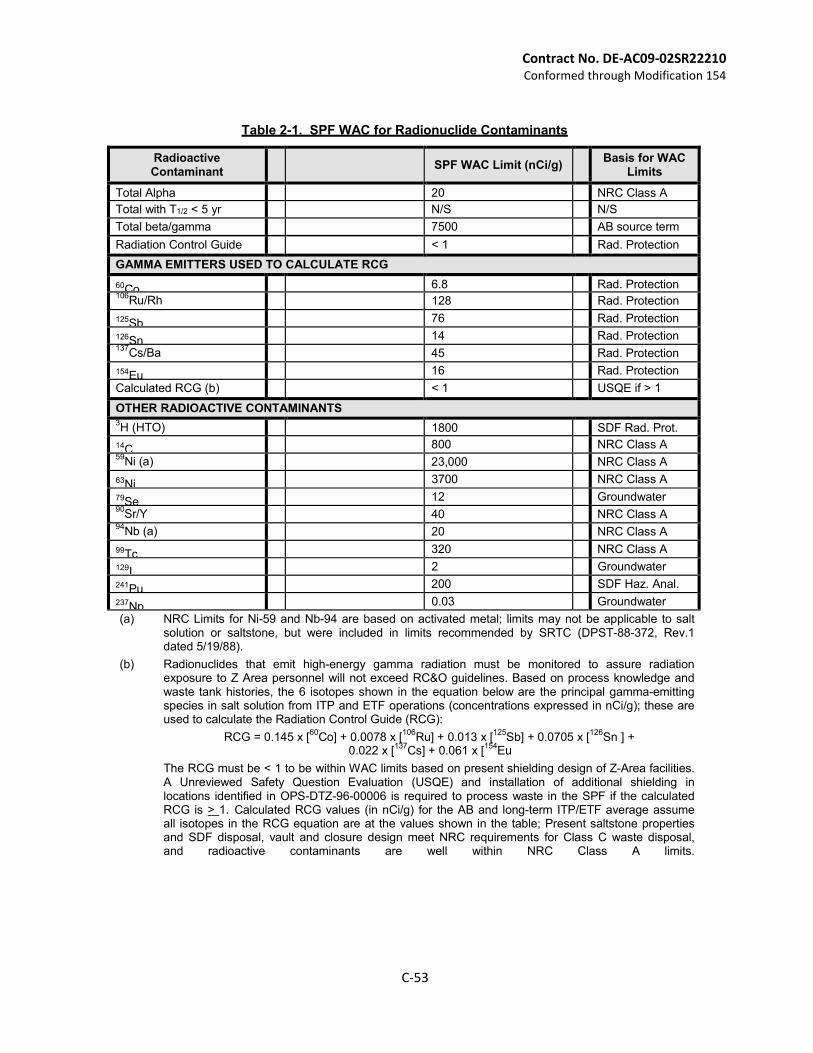
Contract No. DE-AC09-02SR22210 Conformed through Modification 154
C-53
Table 2-1. SPF WAC for Radionuclide Contaminants
Radioactive Contaminant
SPF WAC Limit (nCi/g)
Basis for WAC Limits
Total Alpha 20 NRC Class A
Total with T1/2 < 5 yr N/S N/S
Total beta/gamma 7500 AB source term
Radiation Control Guide < 1 Rad. Protection
GAMMA EMITTERS USED TO CALCULATE RCG
60Co 6.8 Rad. Protection 106
Ru/Rh 128 Rad. Protection
125Sb 76 Rad. Protection
126Sn 14 Rad. Protection 137
Cs/Ba 45 Rad. Protection
154Eu 16 Rad. Protection
Calculated RCG (b) < 1 USQE if > 1
OTHER RADIOACTIVE CONTAMINANTS 3H (HTO) 1800 SDF Rad. Prot.
14C 800 NRC Class A 59
Ni (a) 23,000 NRC Class A
63Ni 3700 NRC Class A
79Se 12 Groundwater 90
Sr/Y 40 NRC Class A 94
Nb (a) 20 NRC Class A
99Tc 320 NRC Class A
129I 2 Groundwater
241Pu 200 SDF Haz. Anal.
237Np 0.03 Groundwater
(a) NRC Limits for Ni-59 and Nb-94 are based on activated metal; limits may not be applicable to salt solution or saltstone, but were included in limits recommended by SRTC (DPST-88-372, Rev.1 dated 5/19/88).
(b) Radionuclides that emit high-energy gamma radiation must be monitored to assure radiation exposure to Z Area personnel will not exceed RC&O guidelines. Based on process knowledge and waste tank histories, the 6 isotopes shown in the equation below are the principal gamma-emitting species in salt solution from ITP and ETF operations (concentrations expressed in nCi/g); these are used to calculate the Radiation Control Guide (RCG):
RCG = 0.145 x [60
Co] + 0.0078 x [106
Ru] + 0.013 x [125
Sb] + 0.0705 x [126
Sn ] + 0.022 x [
137Cs] + 0.061 x [
154Eu
The RCG must be < 1 to be within WAC limits based on present shielding design of Z-Area facilities. A Unreviewed Safety Question Evaluation (USQE) and installation of additional shielding in locations identified in OPS-DTZ-96-00006 is required to process waste in the SPF if the calculated RCG is > 1. Calculated RCG values (in nCi/g) for the AB and long-term ITP/ETF average assume all isotopes in the RCG equation are at the values shown in the table; Present saltstone properties and SDF disposal, vault and closure design meet NRC requirements for Class C waste disposal, and radioactive contaminants are well within NRC Class A limits.
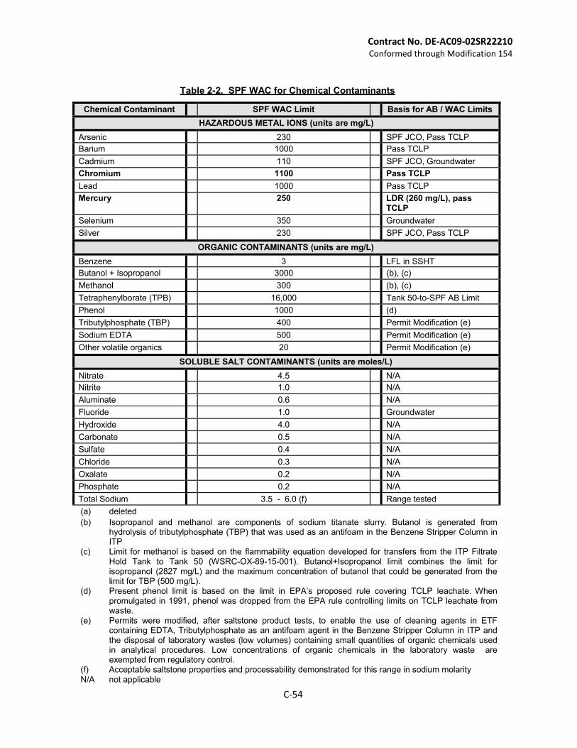
Contract No. DE-AC09-02SR22210 Conformed through Modification 154
C-54
Table 2-2. SPF WAC for Chemical Contaminants
Chemical Contaminant SPF WAC Limit Basis for AB / WAC Limits
HAZARDOUS METAL IONS (units are mg/L)
Arsenic 230 SPF JCO, Pass TCLP
Barium 1000 Pass TCLP
Cadmium 110 SPF JCO, Groundwater
Chromium 1100 Pass TCLP
Lead 1000 Pass TCLP
Mercury 250 LDR (260 mg/L), pass TCLP
Selenium 350 Groundwater
Silver 230 SPF JCO, Pass TCLP
ORGANIC CONTAMINANTS (units are mg/L)
Benzene 3 LFL in SSHT
Butanol + Isopropanol 3000 (b), (c)
Methanol 300 (b), (c)
Tetraphenylborate (TPB) 16,000 Tank 50-to-SPF AB Limit
Phenol 1000 (d)
Tributylphosphate (TBP) 400 Permit Modification (e)
Sodium EDTA 500 Permit Modification (e)
Other volatile organics 20 Permit Modification (e)
SOLUBLE SALT CONTAMINANTS (units are moles/L)
Nitrate 4.5 N/A
Nitrite 1.0 N/A
Aluminate 0.6 N/A
Fluoride 1.0 Groundwater
Hydroxide 4.0 N/A
Carbonate 0.5 N/A
Sulfate 0.4 N/A
Chloride 0.3 N/A
Oxalate 0.2 N/A
Phosphate 0.2 N/A
Total Sodium 3.5 - 6.0 (f) Range tested
(a) deleted
(b) Isopropanol and methanol are components of sodium titanate slurry. Butanol is generated from hydrolysis of tributylphosphate (TBP) that was used as an antifoam in the Benzene Stripper Column in ITP
(c) Limit for methanol is based on the flammability equation developed for transfers from the ITP Filtrate Hold Tank to Tank 50 (WSRC-OX-89-15-001). Butanol+Isopropanol limit combines the limit for isopropanol (2827 mg/L) and the maximum concentration of butanol that could be generated from the limit for TBP (500 mg/L).
(d) Present phenol limit is based on the limit in EPA’s proposed rule covering TCLP leachate. When promulgated in 1991, phenol was dropped from the EPA rule controlling limits on TCLP leachate from waste.
(e) Permits were modified, after saltstone product tests, to enable the use of cleaning agents in ETF containing EDTA, Tributylphosphate as an antifoam agent in the Benzene Stripper Column in ITP and the disposal of laboratory wastes (low volumes) containing small quantities of organic chemicals used in analytical procedures. Low concentrations of organic chemicals in the laboratory waste are exempted from regulatory control.
(f) Acceptable saltstone properties and processability demonstrated for this range in sodium molarity
N/A not applicable
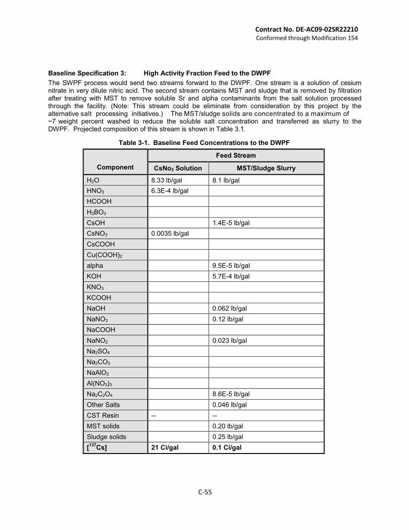
Contract No. DE-AC09-02SR22210 Conformed through Modification 154
C-55
Baseline Specification 3: High Activity Fraction Feed to the DWPF
The SWPF process would send two streams forward to the DWPF. One stream is a solution of cesium nitrate in very dilute nitric acid. The second stream contains MST and sludge that is removed by filtration after treating with MST to remove soluble Sr and alpha contaminants from the salt solution processed through the facility. (Note: This stream could be eliminate from consideration by this project by the alternative salt processing initiatives.) The MST/sludge solids are concentrated to a maximum of ~7 weight percent washed to reduce the soluble salt concentration and transferred as slurry to the DWPF. Projected composition of this stream is shown in Table 3.1.
Table 3-1. Baseline Feed Concentrations to the DWPF
Component
Feed Stream
CsNo3 Solution MST/Sludge Slurry
H2O 8.33 lb/gal 8.1 lb/gal
HNO3 6.3E-4 lb/gal
HCOOH
H3BO3
CsOH 1.4E-5 lb/gal
CsNO3 0.0035 lb/gal
CsCOOH
Cu(COOH)2
alpha 9.5E-5 lb/gal
KOH 5.7E-4 lb/gal
KNO3
KCOOH
NaOH 0.062 lb/gal
NaNO3 0.12 lb/gal
NaCOOH
NaNO2 0.023 lb/gal
Na2SO4
Na2CO3
NaAlO2
Al(NO3)3
Na2C2O4 8.6E-5 lb/gal
Other Salts 0.046 lb/gal
CST Resin -- --
MST solids 0.20 lb/gal
Sludge solids 0.25 lb/gal
[137
Cs] 21 Ci/gal 0.1 Ci/gal
Contract No. DE-AC09-02SR22210 Conformed through Modification 154
C-56
C.9 INTERFACE CONTROL REQUIREMENTS
This Section provides the requirements for interface controls that describe the physical and administrative interfaces between the SWPF Contractor(s), DOE, and the Site M&O contractor.
The objective of the interface management system is to assure documentation and management of shared responsibilities for: (1) transfer of energy, data, or materials; and (2) development, operation, and maintenance of a physical compatible facilities and subsystems.
The approach to managing the interfaces is based upon development of ICDs that identify the requirements, roles, and responsibilities for all parties to the interface. The overall strategy for provision of services will be as follows:
Site M&O contractor provides needed services/equipment up to/near the SWPF Facility boundary (junction to be mutually agreed upon),
SWPF contractor routes services within the SWPF.
The intent of this strategy is for the SWPF contractor’s work to remain within the confines of the “green field” SWPF with the Site M&O performing any work required outside of SWPF boundary.
(a) Proposed ICDs are:
ICD 1: Raw Water ICD 2: Potable Water ICD 3: Radioactive Solid Wastes ICD 4: Non-Radioactive Liquid Effluents ICD 5: Radioactive, Liquid Effluents ICD 6: Liquid Sanitary Wastes ICD 7: Land for Siting ICD 8: Electricity ICD 9: Roads ICD 10: Waste Feed ICD 11: Waste Treatability Samples ICD 12: Emergency Response ICD 13: Telecommunications ICD 14: Steam ICD 15: SWPF Feed to the Saltstone Facility ICD 16: SWPF Feed to the DWPF
(b) The Contractor shall update the ICDs as required throughout the period of Contract performance, ICDs shall reflect all interfaces and services needed in the construction and performance testing phases, and projected interface and services needed for the future commissioning and operating phases. The ICDs shall be an element of the design basis.
(c) The Contractor shall ensure that the ICDs include, at a minimum, details on the following areas consistent with the maturity of the project:
(1) Physical Interfaces: (2)
(i) Location and description of each hand-off point; (ii) Interface block diagrams and schematics that clearly define organizational
responsibilities for each interface (e.g., ownership, construction, and maintenance);
(iii) Type, quantity and composition of material; (iv) Packaging requirements; (v) Design drawings (as appropriate); and (vi) Operations and maintenance requirements.
Contract No. DE-AC09-02SR22210 Conformed through Modification 154
C-57
(3) Administrative Interfaces:
(i) Procedures that define the administrative transfer of interface items (e.g.,
who, what, when, where, and how). (ii) Linkage to the integrated Contractor project baseline. These schedules and
logic must contain detail that demonstrates that the key ICD events or milestones are achievable.
(iii) Documentation necessary for official hand-off of interface items. (iv) Authorization basis and permitting integration.
(4) Acceptance Criteria shall be developed for every hand-off item.
(d) Changes to ICDs will be made in accordance with Standard 1.
C.10 ENHANCED PRELIMINARY DESIGN
Where safety analysis indicates confinement barriers are necessary for workers protection, the SWPF Preliminary Design shall be revised to incorporate a Performance Category-3 (PC-3) designation for safety-related piping, process vessels, and other components that would provide a local confinement barrier. Portions of the facility housing safety-related PC-3 local confinement barriers shall also be designated as PC-3 and designed to resist natural phenomena events. As a defense-in-depth measure, safety-related active ventilation systems shall be provided to protect workers from process upsets involving a significant release of radioactive material due to non- natural phenomena hazards events (e.g., tank overflow or spills). Since the SWPF design will now incorporate local safety-related confinement barriers designed to resist natural phenomena (i.e., PC-3), safety-related ventilation systems will not have to resist natural phenomena to protect facility workers.


![Completion of Request for Proposal, Schedule 1, Standard ... · Declaration: Supporting Schedule to Annex C)]. 1. General Conditions 1.1. Preferential Procurement Regulations, 2017](https://img.pdfslide.us/doc/110x75/5f727297b12dfa3fcf6298ea/completion-of-request-for-proposal-schedule-1-standard-declaration-supporting.jpg)