Embed Size (px)
Citation preview
Part IMaterials Modeling and Simulation: Crystal Plasticity,Deformation, and Recrystallization
Microstructural Design of Advanced Engineering Materials, First Edition. Edited by Dmitri A. Molodov.� 2013 Wiley-VCH Verlag GmbH & Co. KGaA. Published 2013 by Wiley-VCH Verlag GmbH & Co. KGaA.
j1

1Through-Process Modeling of Materials Fabrication: Philosophy,Current State, and Future DirectionsG€unter Gottstein
1.1Introduction
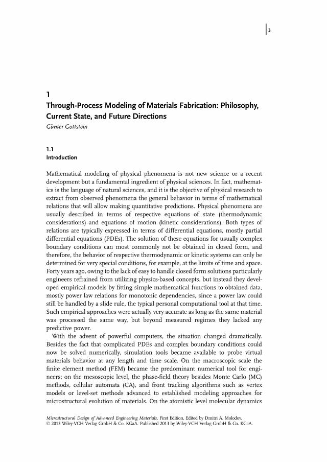
Mathematical modeling of physical phenomena is not new science or a recentdevelopment but a fundamental ingredient of physical sciences. In fact, mathemat-ics is the language of natural sciences, and it is the objective of physical research toextract from observed phenomena the general behavior in terms of mathematicalrelations that will allow making quantitative predictions. Physical phenomena areusually described in terms of respective equations of state (thermodynamicconsiderations) and equations of motion (kinetic considerations). Both types ofrelations are typically expressed in terms of differential equations, mostly partialdifferential equations (PDEs). The solution of these equations for usually complexboundary conditions can most commonly not be obtained in closed form, andtherefore, the behavior of respective thermodynamic or kinetic systems can only bedetermined for very special conditions, for example, at the limits of time and space.Forty years ago, owing to the lack of easy to handle closed form solutions particularlyengineers refrained from utilizing physics-based concepts, but instead they devel-oped empirical models by fitting simple mathematical functions to obtained data,mostly power law relations for monotonic dependencies, since a power law couldstill be handled by a slide rule, the typical personal computational tool at that time.Such empirical approaches were actually very accurate as long as the same materialwas processed the same way, but beyond measured regimes they lacked anypredictive power.With the advent of powerful computers, the situation changed dramatically.
Besides the fact that complicated PDEs and complex boundary conditions couldnow be solved numerically, simulation tools became available to probe virtualmaterials behavior at any length and time scale. On the macroscopic scale thefinite element method (FEM) became the predominant numerical tool for engi-neers; on the mesoscopic level, the phase-field theory besides Monte Carlo (MC)methods, cellular automata (CA), and front tracking algorithms such as vertexmodels or level-set methods advanced to established modeling approaches formicrostructural evolution of materials. On the atomistic level molecular dynamics
j3
Microstructural Design of Advanced Engineering Materials, First Edition. Edited by Dmitri A. Molodov.� 2013 Wiley-VCH Verlag GmbH & Co. KGaA. Published 2013 by Wiley-VCH Verlag GmbH & Co. KGaA.
(MD) simulations enabled a large variety of atomistic phenomena to be explored,and eventually density functional theory allowed ab-initio quantum mechanicalstudies of complex atomistic configurations, to name only the most popularapproaches. With these computational tools at hand, one does not generate newphysics, since the models and tools essentially reflect our understanding of physicalphenomena and the underlying mechanisms. Instead, available computationalpower allows us to address complex phenomena, mutual interaction of differentphysical processes, and nonsteady-state behavior of physical systems. If we confineour consideration to materials, in particular to crystalline solids, specifically com-mercial metallic materials, we have now the option to utilize computer power,sophisticated simulation approaches, and advanced numerical algorithms for theprediction of material properties and therefore, for an optimization of materialsprocessing and materials performance in service, in other words we are now able toput 50 years of physical metallurgy to work.To make reliable predictions of materials behavior one has to understand that,
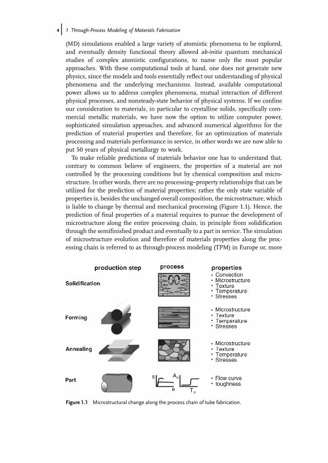
contrary to common believe of engineers, the properties of a material are notcontrolled by the processing conditions but by chemical composition and micro-structure. In other words, there are no processing–property relationships that can beutilized for the prediction of material properties; rather the only state variable ofproperties is, besides the unchanged overall composition, themicrostructure, whichis liable to change by thermal and mechanical processing (Figure 1.1). Hence, theprediction of final properties of a material requires to pursue the development ofmicrostructure along the entire processing chain, in principle from solidificationthrough the semifinished product and eventually to a part in service. The simulationof microstructure evolution and therefore of materials properties along the proc-essing chain is referred to as through-process modeling (TPM) in Europe or, more
Figure 1.1 Microstructural change along the process chain of tube fabrication.
4j 1 Through-Process Modeling of Materials Fabrication
recently, integrated computational materials engineering (ICME) in the UnitedStates. In the following, we will use throughout the term TPM, keeping the identitywith ICME in mind.
1.2Microstructure Evolution
In view of the observed microstructural complexity in commercial materials theprediction of microstructure evolution during processing seems to be an intractableproblem. Hence, it seems surprising at first glance that physical metallurgy researchof the past 80 years has shown that there are only three processes involved thathave to be considered for microstructural change, that is, crystal plasticity,recrystallization and related processes, and phase transformations. Admittedlyeach of these three microstructural processes is very complex and their mutualinteraction can lead to widely different microstructures; the principles have beenlaid out bymetal physics research in the recent past andmathematical concepts existto address microstructure evolution quantitatively. Also, specific relations have beenderived that associate microstructure with material properties.Most of concepts of microstructural phenomena are formulated in a continuum
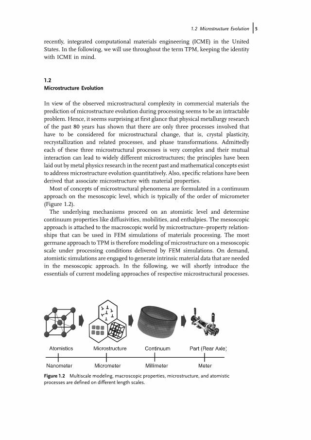
approach on the mesoscopic level, which is typically of the order of micrometer(Figure 1.2).The underlying mechanisms proceed on an atomistic level and determine
continuum properties like diffusivities, mobilities, and enthalpies. The mesoscopicapproach is attached to the macroscopic world by microstructure–property relation-ships that can be used in FEM simulations of materials processing. The mostgermane approach to TPM is therefore modeling of microstructure on a mesoscopicscale under processing conditions delivered by FEM simulations. On demand,atomistic simulations are engaged to generate intrinsic material data that are neededin the mesoscopic approach. In the following, we will shortly introduce theessentials of current modeling approaches of respective microstructural processes.
Figure 1.2 Multiscale modeling, macroscopic properties, microstructure, and atomisticprocesses are defined on different length scales.
1.2 Microstructure Evolution j5
1.3Microstructural Processes
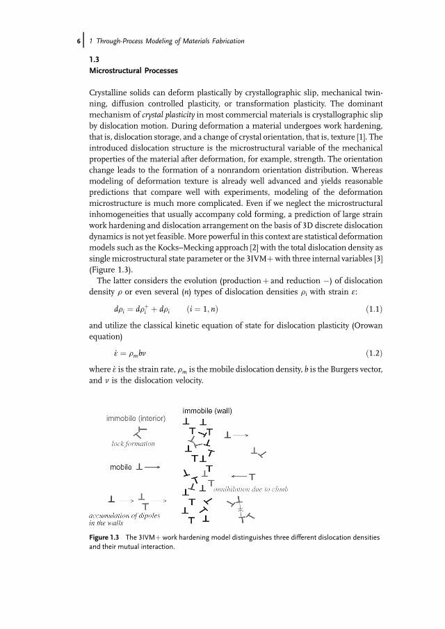
Crystalline solids can deform plastically by crystallographic slip, mechanical twin-ning, diffusion controlled plasticity, or transformation plasticity. The dominantmechanism of crystal plasticity in most commercial materials is crystallographic slipby dislocation motion. During deformation a material undergoes work hardening,that is, dislocation storage, and a change of crystal orientation, that is, texture [1]. Theintroduced dislocation structure is the microstructural variable of the mechanicalproperties of the material after deformation, for example, strength. The orientationchange leads to the formation of a nonrandom orientation distribution. Whereasmodeling of deformation texture is already well advanced and yields reasonablepredictions that compare well with experiments, modeling of the deformationmicrostructure is much more complicated. Even if we neglect the microstructuralinhomogeneities that usually accompany cold forming, a prediction of large strainwork hardening and dislocation arrangement on the basis of 3D discrete dislocationdynamics is not yet feasible. More powerful in this context are statistical deformationmodels such as the Kocks–Mecking approach [2] with the total dislocation density assinglemicrostructural state parameter or the 3IVMþwith three internal variables [3](Figure 1.3).The latter considers the evolution (productionþ and reduction �) of dislocation
density r or even several (n) types of dislocation densities ri with strain e:
dri ¼ drþi þ dri ði ¼ 1; nÞ ð1:1Þand utilize the classical kinetic equation of state for dislocation plasticity (Orowanequation)
_e ¼ rmbv ð1:2Þwhere _e is the strain rate, rm is themobile dislocation density, b is the Burgers vector,and v is the dislocation velocity.
Figure 1.3 The 3IVMþ work hardening model distinguishes three different dislocation densitiesand their mutual interaction.
6j 1 Through-Process Modeling of Materials Fabrication
The strength s is then obtained via the Taylor equation
s ¼ aGbX
f iffiffiffiffiri
p ð1:3Þfi represents the respective volume fraction associated with the dislocation density ri.Respective models can approximate the measured flow curves quite well and are
able to make reasonable predictions for different deformation conditions andchanging alloy composition after optimizing a significant number of unknownphysical parameters. While this development is promising, more detailed investi-gations are necessary to make the models easier to handle and to anticipate themodel parameters by theoretical concepts.Crystallographic slip by dislocation motion proceeds by pure shear and therefore
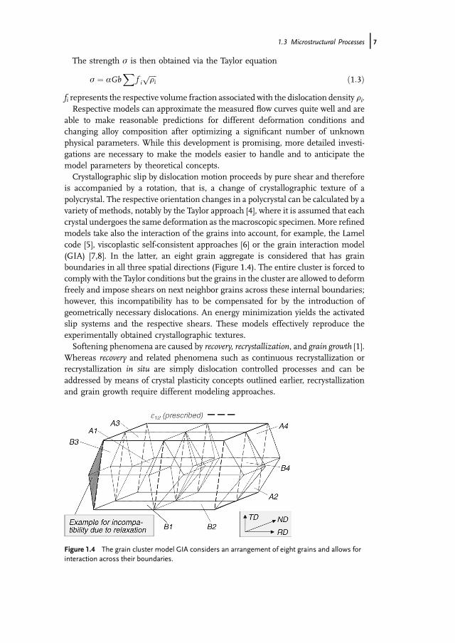
is accompanied by a rotation, that is, a change of crystallographic texture of apolycrystal. The respective orientation changes in a polycrystal can be calculated by avariety of methods, notably by the Taylor approach [4], where it is assumed that eachcrystal undergoes the same deformation as themacroscopic specimen.More refinedmodels take also the interaction of the grains into account, for example, the Lamelcode [5], viscoplastic self-consistent approaches [6] or the grain interaction model(GIA) [7,8]. In the latter, an eight grain aggregate is considered that has grainboundaries in all three spatial directions (Figure 1.4). The entire cluster is forced tocomply with the Taylor conditions but the grains in the cluster are allowed to deformfreely and impose shears on next neighbor grains across these internal boundaries;however, this incompatibility has to be compensated for by the introduction ofgeometrically necessary dislocations. An energy minimization yields the activatedslip systems and the respective shears. These models effectively reproduce theexperimentally obtained crystallographic textures.Softening phenomena are caused by recovery, recrystallization, and grain growth [1].
Whereas recovery and related phenomena such as continuous recrystallization orrecrystallization in situ are simply dislocation controlled processes and can beaddressed by means of crystal plasticity concepts outlined earlier, recrystallizationand grain growth require different modeling approaches.
Figure 1.4 The grain cluster model GIA considers an arrangement of eight grains and allows forinteraction across their boundaries.
1.3 Microstructural Processes j7
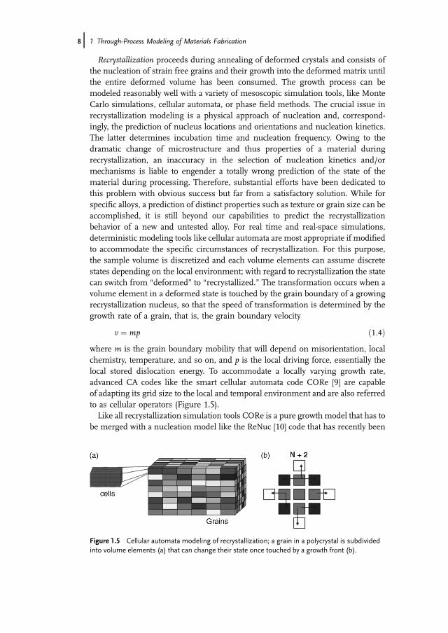
Recrystallization proceeds during annealing of deformed crystals and consists ofthe nucleation of strain free grains and their growth into the deformed matrix untilthe entire deformed volume has been consumed. The growth process can bemodeled reasonably well with a variety of mesoscopic simulation tools, like MonteCarlo simulations, cellular automata, or phase field methods. The crucial issue inrecrystallization modeling is a physical approach of nucleation and, correspond-ingly, the prediction of nucleus locations and orientations and nucleation kinetics.The latter determines incubation time and nucleation frequency. Owing to thedramatic change of microstructure and thus properties of a material duringrecrystallization, an inaccuracy in the selection of nucleation kinetics and/ormechanisms is liable to engender a totally wrong prediction of the state of thematerial during processing. Therefore, substantial efforts have been dedicated tothis problem with obvious success but far from a satisfactory solution. While forspecific alloys, a prediction of distinct properties such as texture or grain size can beaccomplished, it is still beyond our capabilities to predict the recrystallizationbehavior of a new and untested alloy. For real time and real-space simulations,deterministic modeling tools like cellular automata are most appropriate if modifiedto accommodate the specific circumstances of recrystallization. For this purpose,the sample volume is discretized and each volume elements can assume discretestates depending on the local environment; with regard to recrystallization the statecan switch from “deformed” to “recrystallized.” The transformation occurs when avolume element in a deformed state is touched by the grain boundary of a growingrecrystallization nucleus, so that the speed of transformation is determined by thegrowth rate of a grain, that is, the grain boundary velocity
v ¼ mp ð1:4Þwhere m is the grain boundary mobility that will depend on misorientation, localchemistry, temperature, and so on, and p is the local driving force, essentially thelocal stored dislocation energy. To accommodate a locally varying growth rate,advanced CA codes like the smart cellular automata code CORe [9] are capableof adapting its grid size to the local and temporal environment and are also referredto as cellular operators (Figure 1.5).Like all recrystallization simulation tools CORe is a pure growth model that has to
be merged with a nucleation model like the ReNuc [10] code that has recently been
Figure 1.5 Cellular automata modeling of recrystallization; a grain in a polycrystal is subdividedinto volume elements (a) that can change their state once touched by a growth front (b).
8j 1 Through-Process Modeling of Materials Fabrication
developed for aluminum alloys to output nucleation rates for typical nucleationmechanisms such as recrystallization at grain boundaries, transition bands, shearbands or at large particles [11]. Given the nucleation frequency and nucleus texturethe kinetics of recrystallization, grain size distribution and texture development canbe computed.Recrystallization is succeeded by grain growth, which is observed by a coarsening
of the grain structure. It is driven by grain boundary curvature and proceeds by grainboundary motion with local migration rate
v ¼ m2cR
ð1:5Þ
where c is the specific grain boundary energy and R is the local radius of theboundary curvature [1].Grain growth can be simulated by a variety of methods such as the phase field
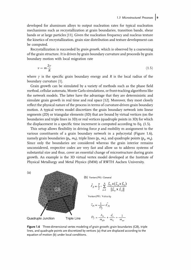
method, cellular automata,Monte Carlo simulations, or front-tracking algorithms likethe network models. The latter have the advantage that they are deterministic andsimulate grain growth in real time and real space [12]. Moreover, they most closelyreflect the physical nature of the process in terms of curvature-driven grain boundarymotion. A typical vertex model discretizes the grain boundary network into linearsegments (2D) or triangular elements (3D) that are bound by virtual vertices (on theboundaries and triple lines in 3D) or real vertices (quadruple points in 3D) for whichthe displacement in a specific time increment is computed according to Eq. (1.5).This setup allows flexibility in driving force p and mobility m assignment to the
various constituents of a grain boundary network in a polycrystal (Figure 1.6),namely grain boundaries (pb,mb), triple lines (pt, mt), and quadruple points (pq, mq).Since only the boundaries are considered whereas the grain interior remainsunconsidered, respective codes are very fast and allow us to address systems ofsubstantial size and thus, cover an essential change of microstructure during graingrowth. An example is the 3D virtual vertex model developed at the Institute ofPhysical Metallurgy and Metal Physics (IMM) of RWTH Aachen University.
Figure 1.6 Three-dimensional vertex modeling of grain growth; grain boundaries (GB), triplelines, and quadruple points are discretized by vertices (a) that are displaced according to theequation of motion (b) under local conditions.
1.3 Microstructural Processes j9
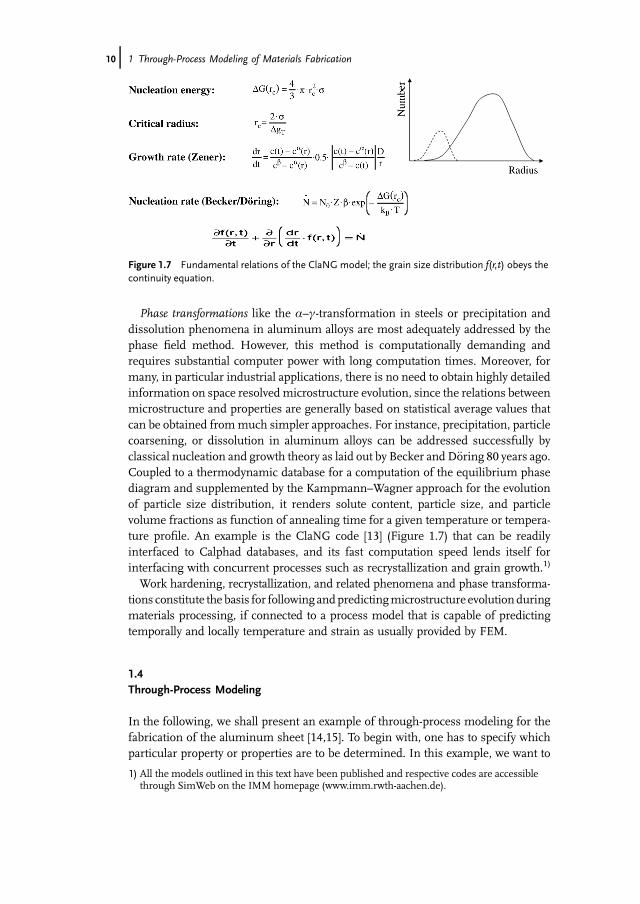
Phase transformations like the a–c-transformation in steels or precipitation anddissolution phenomena in aluminum alloys are most adequately addressed by thephase field method. However, this method is computationally demanding andrequires substantial computer power with long computation times. Moreover, formany, in particular industrial applications, there is no need to obtain highly detailedinformation on space resolvedmicrostructure evolution, since the relations betweenmicrostructure and properties are generally based on statistical average values thatcan be obtained frommuch simpler approaches. For instance, precipitation, particlecoarsening, or dissolution in aluminum alloys can be addressed successfully byclassical nucleation and growth theory as laid out by Becker and D€oring 80 years ago.Coupled to a thermodynamic database for a computation of the equilibrium phasediagram and supplemented by the Kampmann–Wagner approach for the evolutionof particle size distribution, it renders solute content, particle size, and particlevolume fractions as function of annealing time for a given temperature or tempera-ture profile. An example is the ClaNG code [13] (Figure 1.7) that can be readilyinterfaced to Calphad databases, and its fast computation speed lends itself forinterfacing with concurrent processes such as recrystallization and grain growth.1)
Work hardening, recrystallization, and related phenomena and phase transforma-tions constitute the basis for following andpredictingmicrostructure evolutionduringmaterials processing, if connected to a process model that is capable of predictingtemporally and locally temperature and strain as usually provided by FEM.
1.4Through-Process Modeling
In the following, we shall present an example of through-process modeling for thefabrication of the aluminum sheet [14,15]. To begin with, one has to specify whichparticular property or properties are to be determined. In this example, we want to
Figure 1.7 Fundamental relations of the ClaNG model; the grain size distribution f(r,t) obeys thecontinuity equation.
1) All the models outlined in this text have been published and respective codes are accessiblethrough SimWeb on the IMM homepage (www.imm.rwth-aachen.de).
10j 1 Through-Process Modeling of Materials Fabrication
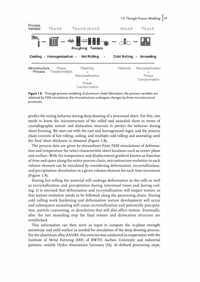
predict the earing behavior during deep drawing of a processed sheet. For this, oneneeds to know the microstructure of the rolled and annealed sheet in terms ofcrystallographic texture and dislocation structure to predict the behavior duringsheet forming. We start out with the cast and homogenized ingot, and the processchain consists of hot rolling, coiling, and multiple cold rolling and annealing untilthe final sheet thickness is obtained (Figure 1.8).The process data are given by streamlines from FEM simulations of deforma-
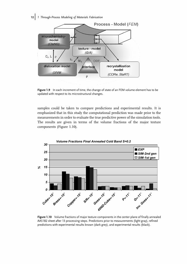
tion and temperature for select characteristic sheet locations such as center planeand surface. With the temperature and displacement gradient known as functionof time and space along the entire process chain, microstructure evolution in eachvolume element can be simulated by considering deformation, recrystallization,and precipitation–dissolution in a given volume element for each time increment(Figure 1.9).During hot rolling the material will undergo deformation in the rolls as well
as recrystallization and precipitation during interstand times and during coil-ing. It is stressed that deformation and recrystallization will impact texture sothat texture evolution needs to be followed along the processing chain. Duringcold rolling work hardening and deformation texture development will occurand subsequent annealing will cause recrystallization and potentially precipita-tion, particle coarsening, or dissolution that will also affect texture. Eventually,after the last annealing step the final texture and dislocation structure areestablished.This information can then serve as input to compute the in-plane strength
anisotropy and yield surface as needed for simulation of the deep drawing process.For the aluminum alloy AA5182, this exercise was conducted in cooperation with theInstitute of Metal Forming (IBF) of RWTH Aachen University and industrialpartners, notably Hydro Aluminium Germany [16]. At defined processing steps,
Figure 1.8 Through-process modeling of aluminum sheet fabrication; the process variables areobtained by FEM simulations, the microstructure undergoes changes by three microstructuralprocesses.
1.4 Through-Process Modeling j11
samples could be taken to compare predictions and experimental results. It isemphasized that in this study the computational prediction was made prior to themeasurements in order to evaluate the true predictive power of the simulation tools.The results are given in terms of the volume fractions of the major texturecomponents (Figure 1.10).
Volume Fractions Final Annealed Cold Band S=0.2
0
5
10
15
20
25
30
%
EXPSIM-2nd genSIM-1st gen
Cube+-1
5°
Brass
+-15
°
Copper+-
15°
S/R+-
15°
Goss+-
15°
45ND-C
ube+-1
5°
P+-11
°
Q+-11
°
Inv.
Goss+-
11°
Figure 1.10 Volume fractions of major texture components in the center plane of finally annealedAA5182 sheet after 13 processing steps. Predictions prior to measurements (light gray), refinedpredictions with experimental results known (dark grey), and experimental results (black).
Figure 1.9 In each increment of time, the change of state of an FEM volume element has to beupdated with respect to its microstructural changes.
12j 1 Through-Process Modeling of Materials Fabrication
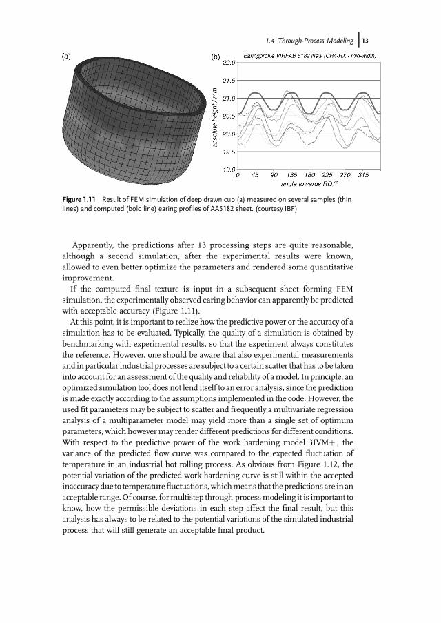
Apparently, the predictions after 13 processing steps are quite reasonable,although a second simulation, after the experimental results were known,allowed to even better optimize the parameters and rendered some quantitativeimprovement.If the computed final texture is input in a subsequent sheet forming FEM
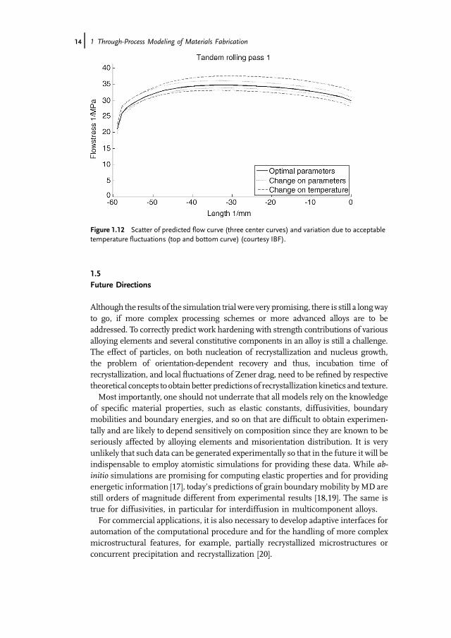
simulation, the experimentally observed earing behavior can apparently be predictedwith acceptable accuracy (Figure 1.11).At this point, it is important to realize how the predictive power or the accuracy of a
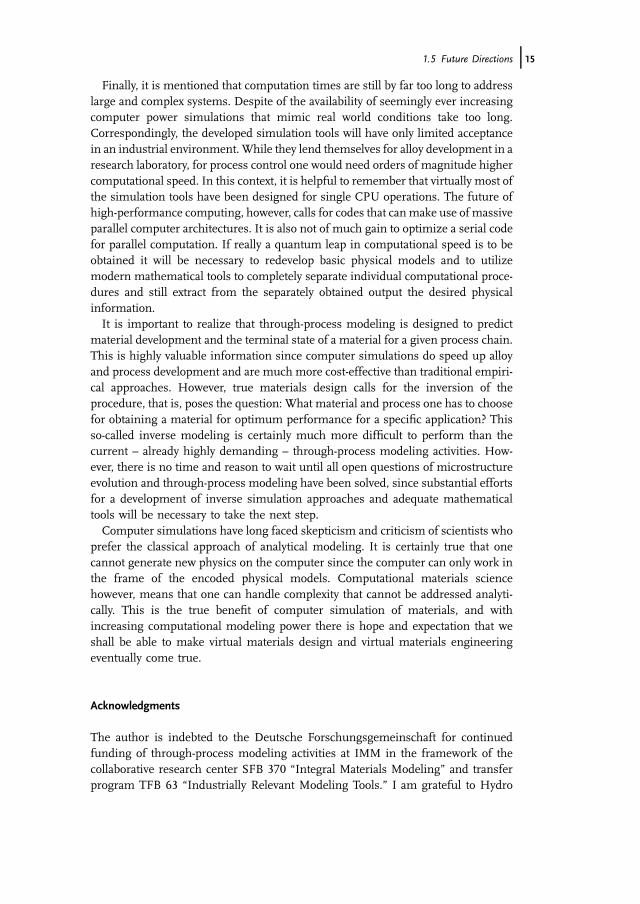
simulation has to be evaluated. Typically, the quality of a simulation is obtained bybenchmarking with experimental results, so that the experiment always constitutesthe reference. However, one should be aware that also experimental measurementsand in particular industrial processes are subject to a certain scatter that has to be takeninto account for an assessment of the quality and reliability of amodel. In principle, anoptimized simulation tool does not lend itself to an error analysis, since the predictionis made exactly according to the assumptions implemented in the code. However, theused fit parameters may be subject to scatter and frequently a multivariate regressionanalysis of a multiparameter model may yield more than a single set of optimumparameters, which howevermay render different predictions for different conditions.With respect to the predictive power of the work hardening model 3IVMþ , thevariance of the predicted flow curve was compared to the expected fluctuation oftemperature in an industrial hot rolling process. As obvious from Figure 1.12, thepotential variation of the predicted work hardening curve is still within the acceptedinaccuracy due to temperaturefluctuations,whichmeans that the predictions are in anacceptable range.Of course, formultistep through-processmodeling it is important toknow, how the permissible deviations in each step affect the final result, but thisanalysis has always to be related to the potential variations of the simulated industrialprocess that will still generate an acceptable final product.
Figure 1.11 Result of FEM simulation of deep drawn cup (a) measured on several samples (thinlines) and computed (bold line) earing profiles of AA5182 sheet. (courtesy IBF)
1.4 Through-Process Modeling j13
1.5Future Directions
Although the results of the simulation trialwere very promising, there is still a longwayto go, if more complex processing schemes or more advanced alloys are to beaddressed. To correctly predict work hardening with strength contributions of variousalloying elements and several constitutive components in an alloy is still a challenge.The effect of particles, on both nucleation of recrystallization and nucleus growth,the problem of orientation-dependent recovery and thus, incubation time ofrecrystallization, and local fluctuations of Zener drag, need to be refined by respectivetheoretical concepts toobtain better predictionsof recrystallizationkinetics and texture.Most importantly, one should not underrate that all models rely on the knowledge
of specific material properties, such as elastic constants, diffusivities, boundarymobilities and boundary energies, and so on that are difficult to obtain experimen-tally and are likely to depend sensitively on composition since they are known to beseriously affected by alloying elements and misorientation distribution. It is veryunlikely that such data can be generated experimentally so that in the future it will beindispensable to employ atomistic simulations for providing these data. While ab-initio simulations are promising for computing elastic properties and for providingenergetic information [17], today’s predictions of grain boundarymobility byMD arestill orders of magnitude different from experimental results [18,19]. The same istrue for diffusivities, in particular for interdiffusion in multicomponent alloys.For commercial applications, it is also necessary to develop adaptive interfaces for
automation of the computational procedure and for the handling of more complexmicrostructural features, for example, partially recrystallized microstructures orconcurrent precipitation and recrystallization [20].
Figure 1.12 Scatter of predicted flow curve (three center curves) and variation due to acceptabletemperature fluctuations (top and bottom curve) (courtesy IBF).
14j 1 Through-Process Modeling of Materials Fabrication
Finally, it is mentioned that computation times are still by far too long to addresslarge and complex systems. Despite of the availability of seemingly ever increasingcomputer power simulations that mimic real world conditions take too long.Correspondingly, the developed simulation tools will have only limited acceptancein an industrial environment. While they lend themselves for alloy development in aresearch laboratory, for process control one would need orders of magnitude highercomputational speed. In this context, it is helpful to remember that virtually most ofthe simulation tools have been designed for single CPU operations. The future ofhigh-performance computing, however, calls for codes that canmake use of massiveparallel computer architectures. It is also not of much gain to optimize a serial codefor parallel computation. If really a quantum leap in computational speed is to beobtained it will be necessary to redevelop basic physical models and to utilizemodern mathematical tools to completely separate individual computational proce-dures and still extract from the separately obtained output the desired physicalinformation.It is important to realize that through-process modeling is designed to predict
material development and the terminal state of a material for a given process chain.This is highly valuable information since computer simulations do speed up alloyand process development and are much more cost-effective than traditional empiri-cal approaches. However, true materials design calls for the inversion of theprocedure, that is, poses the question: What material and process one has to choosefor obtaining a material for optimum performance for a specific application? Thisso-called inverse modeling is certainly much more difficult to perform than thecurrent – already highly demanding – through-process modeling activities. How-ever, there is no time and reason to wait until all open questions of microstructureevolution and through-process modeling have been solved, since substantial effortsfor a development of inverse simulation approaches and adequate mathematicaltools will be necessary to take the next step.Computer simulations have long faced skepticism and criticism of scientists who
prefer the classical approach of analytical modeling. It is certainly true that onecannot generate new physics on the computer since the computer can only work inthe frame of the encoded physical models. Computational materials sciencehowever, means that one can handle complexity that cannot be addressed analyti-cally. This is the true benefit of computer simulation of materials, and withincreasing computational modeling power there is hope and expectation that weshall be able to make virtual materials design and virtual materials engineeringeventually come true.
Acknowledgments
The author is indebted to the Deutsche Forschungsgemeinschaft for continuedfunding of through-process modeling activities at IMM in the framework of thecollaborative research center SFB 370 “Integral Materials Modeling” and transferprogram TFB 63 “Industrially Relevant Modeling Tools.” I am grateful to Hydro
1.5 Future Directions j15
Aluminium Germany for continued support and encouragement as well as forproviding processed material. Special thanks go to the Institute of Metal Forming(IBF) of RWTH Aachen University for conducting the FEM computations and formany years of excellent cooperation. Finally I like to acknowledge all my doctoralstudents and post-docs who were engaged in through-processmodeling programs atIMM, notably Volker Mohles, Luis Barrales-Mora, Mischa Crumbach, MatthiasGoerdeler, Carmen Sch€afer and many more. Finally, I want to thank MatthiasLoeck, head of our computer department for his personal engagement in codedevelopment, SimWeb design and his valuable support of computational proceduresat IMM.
References
1 Gottstein, G. (2004) Physical Foundations ofMaterials Science, Springer, Berlin.
2 Mecking, H. and Kocks, U.F. (1981)Kinetics of flow and strain hardening. ActaMetallurgica, 29, 1865–1875.
3 Roters, F., Raabe, D., and Gottstein, G.(2000) Work hardening in heterogeneousalloys: A microstructural approach basedon three internal state variables. ActaMaterialia, 48, 4181–4189.
4 Taylor, G.I. (1938) Plastic strain in metals.Institute of Metals, 662, 307–324.
5 Van Houtte, P., Delannay, L., andSamajdar, I. (1999) Quantitative predictionof cold rolling textures in low-carbon steelby means of the LAMEL model. Texturesand Microstructures, 31, 109–149.
6 Molinari, A., Canova, G.R., and Ahzi, S.(1987) A self consistent approach of thelarge deformation polycrystalviscoplasticity. Acta Metallurgica, 35,2983–2994.
7 Crumbach, M., Pomana, G., Wagner, P.,and Gottstein, G. (2001) A Taylor typedeformation texture model consideringgrain interaction and material properties:Part I. fundamentals, in Recrystallizationand Grain Growth (eds G. Gottstein and D.Molodov), Springer, Berlin, pp. 1053–1060.
8 Crumbach, M., Pomana, G., Wagner, P.,and Gottstein, G. (2001) A Taylor typedeformation texture model consideringgrain interaction and material properties:Part II. Experimental validation andcoupling to FEM, in Recrystallization andGrain Growth (eds G. Gottstein and D.Molodov), Springer, Berlin, pp. 1061–1068.
9 Mukhopadhyay, P., Loeck, M., andGottstein, G. (2007) A cellular operatormodel for the simulation of staticrecrystallization. Acta Materialia, 55,551–564.
10 Crumbach, M., Goerdeler, M., andGottstein, G. (2006) Modelling ofrecrystallization textures in aluminiumalloys: I. Model set-up and integration. ActaMaterialia, 54, 3275–3289.
11 Sch€afer, C., Song, J., and Gottstein, G.(2009) Modeling of texture evolutionin the deformation zone of second-phaseparticles. Acta Materialia, 57,1026–1034.
12 Barrales Mora, L.A., Gottstein, G., andShvindlerman, L.S. (2008) Three-dimensional grain growth: Analyticalapproaches and computer simulations.Acta Materialia, 56, 5915–5926.
13 Schneider, M., Gottstein, G., L€ochte, L.,and Hirsch, J. (2002) A statistical model forprecipitation – applications to commercialAl–Mn–Mg–Fe–Si alloys, in AluminiumAlloys. Their Physical and MechanicalProperties (eds P.J. Gregson and S.J.Harris), Trans Tech Publications,Switzerland, pp. 637–642.
14 Gottstein, G. (ed.) (2007) Integral MaterialsModeling: Toward Physics Based Through-Process Models, Wiley-VCH, Weinheim.
15 Hirsch, J. (ed.) (2006) Virtual Fabrication ofAluminum Products, Wiley-VCH,Weinheim
16 Crumbach, M., Goerdeler, M., Gottstein,G., Neumann, L., Aretz, H., and Kopp, R.(2004) Through-process texture modelling
16j 1 Through-Process Modeling of Materials Fabrication

of aluminium alloys.Modelling andSimulation in Materials Science andEngineering, 12, S1–S18.
17 Counts, W.A., Fri�ak, M., Raabe, D., andNeugebauer, J. (2009) Using ab initiocalculations in designing bcc Mg–Li alloysfor ultra-lightweight applications. ActaMaterialia, 57, 69–76.
18 Sch€onfelder, B., Gottstein, G., andSvindlerman, L.S. (2006) Atomisticsimulations of grain boundary migration
in copper.Metallurgical and MaterialsTransactions, 37, 1757–1771.
19 Zhou, J. and Mohles, V. (2011) Towardsrealistic molecular dynamics simulationsof grain boundary mobility. Acta Materialia,59, 5997–6006.
20 Sch€afer, C., Mohles, V., and Gottstein, G.(2011) Modeling of non-isothermalannealing: Interaction of recrystallization,recovery, and precipitation. Acta Materialia,59, 6574–6587.
References j17