Embed Size (px)
Citation preview
'"
'"
TRIENNIAL INSPECTION, LEWIS LAB ORATORY October, 1957 - High Energy Rocket P ropellants
Part I
In the center of the room (POINT) is a r ocket thrust chambe r used for experi
ments with high ener gy rocket propellants . In the thrust chamber (POINT TO
SCHEMATIC: T URN ON lJGHTS) chemical energy released from the combustion of
a fuel and an oxidizer produces a high velocity jet, giving the r ocket its push. In
the complete system the fuel and oxidizer are fed into this thrust chamber by means
of turbine driven pum ps. There are many fuel and oxidizer combinations tha t can
be burned in these engines. This is a spectrum of the relative ener gy that various
fuel and oxidizer c ombinations will import to a missile. The base point at one is
a typical solid propellant.
Solid propellants are in large use today in assist take - off devices and in
mis s iles such as Honest John, and the Nike Booster. Red fuming nitric acid and
dimethylhydr azine is used in the second s tage of the Vanguard s atellite vehicle.
Oxygen and rocket jet fuel is the combination used in our intermediate range and
inte r continental ballis tic missiles such as Jupiter, Thor, Atlas, and T itan.
These propellants repr esent the present state of the art. The Intercontinental
ballistic missile and the Vanguard satellite vehicle represent what can be done in
the way of long range vehicles using these propellants. The Vanguard is a 3-stage
vehicle that will hurl a 20 pound payload the size of a basketball into a satellite
orbit 300 miles above the earth. The first stage burns oxygen and jet fuel (P OINT TC
TANKS). When these propellants are exhausted this stage drops away and a
small solid propeUant rocket puts the satellite into its orbit. Note the large
proportion of this vehicle that is propellant - about 88 percent~
0(
0(
"
..
..
4

,
>
.
~
4
- 2
Part I Continued
There are other higher energy propellant combinations that we can consider
for future r ocket vehicles beyond Vanguar d but considerable research is needed to
put them into practical use. For example , ammonia, fluorine , hydrazine-fluorine ,
hydr ogen-oxygen, hydrogen-fluorine , and hydr ogen- ozone. We are interested in
these propellants because they can put higher speeds into a payload, thus giving
longer r ange, or can give the s ame r ange with less propellant. . As an example of what we might want to do with these higher-energy
• propellants let's consider a manned s atellite glider. Suppose it is to be hurled r
into an orbit 1,000 miles above the ear th. Note it has wings for the r eturn glide to
the earth. Using a conventional propellant combination, for example , oxygen and jet
fuel , the vehicle might look like this , with 3 rocket stages (POINT).
On the other hand suppose we had selected a high energy propellant say
fluorine-ammonia (P OINT TO BOARD) and used the same manned satellite glider
(HOW IT UP). The higher ene r gy of this combination may result in a total
vehicle - glider plus boosters - like this (P OINT) which may require less than half
the weight , size, and thrust of the former one . The larger vehicle using present day
propellants may be so large as to be impractical. "
.. When we try to apply these high energy propellants t o practical r ocket
... .. systems we run into problems that are the result of unique properties of each of
.... these propellants.. For example, on the fuel side we see hydrogen (P OINT), which we liquefy at«
- ...
the very low temperature of -4230 F, even then it has a very low denSity, only ~
about 1/10 that of jet fuel, so that large, well insulated tanks are required. On
. ...
~

.
I"
)
"..
,
..
..
,
'"
'"
~
~
,
or
- 3
Part I - Continued
the oxidant side is ozone (POINT). Techniques for satisfactorily stabilizing
ozone must be developed. Jarring it or heating it or contacting it with the
wrong material causes it to detonate violently. And there is fluorine , the most
potent oxidizer in the whole periodic table of elements (POINT). Mr . Kinney , the
next speaker, will discuss these problems in more detail and the kinds of work
that we are dOing at this laboratory to put high energy propellants into practical
use. Mr. Kinney will be assisted in some demonst r ations of the problems by
Mr. DeWitt.
•
..
•
)
"
. ..
..
~
..
...,
..
.. ~
...

--
PART II
.... Because fluorine is so prominent on our list of high energy propellants
(POINT) we have selected it to illustrate our research. The very thing that leads
to selection of fluor ine for high energy prop:;llant combination also makes unique ~
pr oblems in its use; it is a very powerful oxidizer.
Let us consider first the problem of containing flun rine in tanks, lines , valves ,
pumps, and other parts of a r ocket feed system. There are two asp:;cts to this
pr oblem: 1) selection of material; 2) techniques of using materials. Consider ~
selection of materials. Our research has found a number of materials s atisfactory
, .. for construction of tanks , lines, impellers, and parts of valves (P OINT); for example, )
we use nickel, monel, stainless steel, copp:; r , and brass. Invariably, we need seals 0
. '" packings for valves or pumps. Because fluorine is such a potent oxidizer very few
s oft or rubber-like materials are available for this service. Now for gaskets ,. ...
packings , etc. - you normally think of asbestos as being quite satisfactory being .,.. \"'
fireproof and inert to corrosive fluids. Here is a piece of asbestos (HOLD IT UP).
.. We wish to blow s ome cool r aw fluorine gas against it from a tube like this. Be
cause fluorine is s o poisonous we can' t do this right in froIt of you, but we put a
piece of asbestos just like this one in this box with a window on it. Mr. Schmidt
will op:;n a valve letting fluorine blow against the asbestos. See what ha ppens.
Actually, there is only one plastic available for fluorine service. That
material is a polyethylene plastic , a plastic that is al ready fluorinated. However,
is has serious limitations to its u.3e. A rubber-like material for gaskets, seals,
and pac kings represents a continuing need.
...
....
.. '" ..
...
...
<I/.
..
- 2
Par t II Continued
Let us now consider the techniques of using materials. For example, take the
matter of cleanliness. Here is a piece of steel. This end has been kept very clean;
this end, I've been handling - I now have put some grease on it just from my• » fingers. Here is a double tube that could blow fluorine on both ends of this
s t rip (DEMONSTRATE). I'd like to blow s ome fluorine against both the clean and the• dirty end but again because fluorine is poisonous , I can't do this right in fr ont
~ of you. The same kind of s teel strip and two tubes just like these are set up in
.. this demonstration box. Mr . Schmidt will blow s ome fluorine through these tubes .... against both ends (WATCH). You see that the handled end, the end with the bit of
*' grease contamination, burst into flame. In using materials for fluorine service,
f practices must resemble those of the hospital operating room, rather than those of
the machine shop to prevent the slightest contamination. Actually our mechanics
use rubber gloves in handling material that is being put into fluorine service.
So the things that we have lear ned about containing elemental liquid fluorine
are to select suitable materials , to apply them correctly, and to use techniques
.. that scrupulously avoid even s light contamination.
'" '" .. Looking at the engine again, we see the injector. In this part of the engine,
... the fuel and the oxidant are brought together to prepare them for combustion. We
-<
,. want to know how to design this injecto r so that the propellants will burn efficiently
during the very short time they are in the chamber. This time is of the order
Co of 1/200 of a second. ..
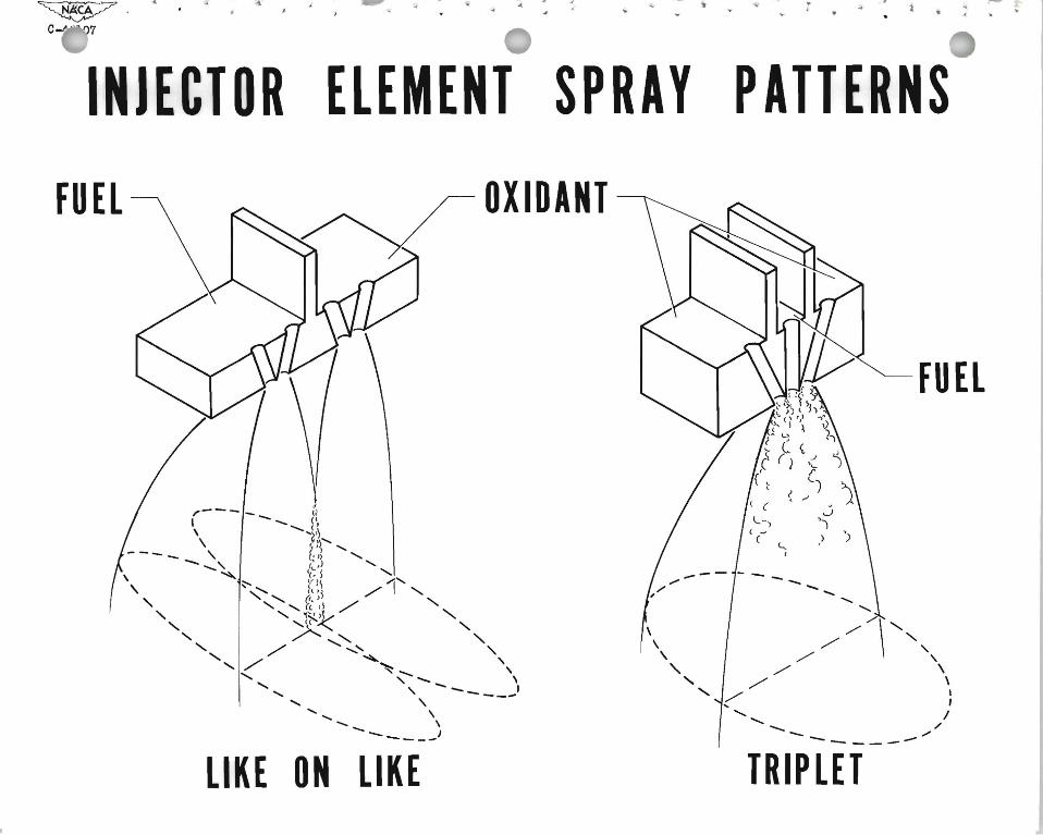
An approach that we are using to this problem has been to isolate and study..,
'~ the elementary parts of the injector systems, and here (demonstrating) is a single

•
.
.,.
...
'"
- 3 Part II - Continued
element from this injector. It's a small part of the injector, you can't see it
very well , but it s imply consists of a small number of fuel and oxidizer holes.
Different injection s pray patterns can be realized by the method of
locating these holes. The object of working with s ingle element injectors is to
determine the best injection spray pattern to properly mix the fuel and oxidizer.
We have been conducting studies with s ingle injectors. The hardware looks like this. .. In this next slide are illustrated typical data from an injector element
• study (explain the slide and data). This illustrates the kind of information that
~ we are getting. ~
But high thrus t rocket engines require large flow rates from many combinations
~ of single elements. With these injectors the individual sprays will simply interact -t
with one another. The result of this interaction has been studied in engines like ~
this one containing s ix elements (show) . •
Finally, injectors for engines of a practical size containing perh?-ps hundreds
.'. of such elements a re studied. Like this one (show). The new facility in
.. which we are seated is used for studies of these injectors , in fact , this one will be
.. put into here next week. ..
.... A third important engineering problem is that of cooling the engine when we
have the high temperature of fluorine supported combustion. In the left-hand
side of the demonstration box is a simulated rocket engine. Its chamber is made
of transparent plastic like the tube I am holding. Mr. Schmidt will ignite the
engine and run it on hydrocarbon-oxygen. Then after the engine is runriing, he
will introduce fluorine along with the oxygen. You will be seeing the flame without •
and then with fluorine. We have a water-cooled temperature probe in the flame

,
"
- 2 Part II - Continued
"
~
to indicate changes in temper atur e , it will r ead on this dial. (Mr. Schmidt
Demonstr ates). Actually fluorine supported flames may be as much as 2 or 3 • thousand degrees hotter than oxygen hydrocarbon flames which a t 50000 F are al ready
• , ~ difficult to cool. Incidentally, this is one of the few times that a group h~s eve r ~
witnes sed fluorine combustion in r ockets .
.. The problems that we have discussed have been mate r ials for the feed ~
sys tems and techniques of using them (point out on engine). The pr oblem of a
learning how to design injector s for efficient combustion; and we have pointed out the ~
cooling problem. These are but a few of the many problems as s ociated with high
energy propellants. The design of gas genera tors , turbines and pumps was not
" discussed. Nor did we discuss exhaust nozzle design or engine contr ol; to name a
... few of the otlier pr oblems that ar e inherent in an engine of this type. Actually, each
of these is unde r s tudy at this labor atory. Time does not pe r mit discussion of these,•
but we have a motion picture which shows typical facilities and activities associated
with r esearch on them (movie). Eventually, all of the individual findings on how to
use a high energy pr opellant must be fed into a research s tudy of the comple te rocket""
.., engine system. That is when you find out whether or not the individual problems
., have really been s olved and that is when you find out the new problems that arise ..
from putting all the parts together.
... The facility that you are visiting now is designed to explore the problems .01
of high energy propellants with engines of practical scale, and with all of the • assembled components. It complements the smaller facilities that have been in use
for the last few years. I would like now to introduce to you Mr. Rothenberg who
will describe this new facility for you.
-
;
.
--
PART III
Here is a view of this facility. We can best describe it be telling ~ ou how ".
we use it.'" ~ ..
You are seated here in the test cell. Outside and on the hill behind the tes t
cell is wher e we store the fuels and oxidants. In pr ep;tr ing for a run we transfer
these to propellant tanks located in sep;trate concr ete pits just behind you. The . ~ tanks ar e then pr essurized with inert gas which is stored her e.
F or a closer look at the test area we will show y ou a s ectional view of this
. ~ much of the fac ility. Here again are the propellant tanks . The high pressur e
gas then forces the propellant to the vertically firing engine here.
~ Because we're in a fair ly populated area, we must remove harmful exhaust
products and silence the roar of the engine. Both these functions are accomplished . ,
• ., by this scrubber- silencer; where these water sprays quench the exhaust and these
absorb fluorine compounds which would be harmful to personnel if permitted to " , • escape. About 50,000 GPM, introduced by many spray nozzles , is required for this
scrubbing. The cleaned gases leave through the vertical stack.
These wate r s prays are also intended to provide silencing. In fact when we
operated the facility this summer, we wer e very s atisfied with the s ilencing we got. ~
Now let' s go back to our firs t slide. Here is the scrubber-silencer we have
been discussing. The water for it is stored in this 450,000 gallon reservoir and is <" 'T
~ gr avity -fed to the scrubber. This arrangement takes advantage of the natural
terrain, eliminating the need for costly, high cap;tcity pumps. The waste water is
~ ,J collected in this detention tank where the fluorine compounds are chemically
• treated and removed. By collecting all the water we prevent contamination of this
~
stream.
The operation of the facility is controlled from a station about 1/2 mile awa~

"I"
'
~
- 2
Part III - Continued .....
in the main laboratory area. Here is a photograph of the control and instrumentl'
.. .. center. You have already been here for the nuclear propulsion talk. The engine
operation is performed from this control console. All engine data are recorded p
in this inst rument section. You'll notice that we use TV to view the r ocket
dur ing operation.
This concludes our discussion. Before you board the bus you will have a
.. . few minutes to look over the facility. As you leave by this door the scrubber
s ilencer is to your left. Thank you.
~
~
'" ,.
..
....
~
..
""
I


',. I ." ~~
~ .. ~ .6140
~ - w~ - ~ . ~- --=f-=:=. _ ~.
I ~-I r::

~
1
~ ,.46096
,~
~ ... , or
ROCKET ENGINE PROBLEM AREAS
NOZZLE DESIGN
CONTROLS COMBUSTION

.. / ~ ,. NACA ... .. ""4'~ C......4 l06
INJECTOR PERFORMANCE
SHOWERHEAD PARALLEL TRIPLET SHEETS
o~ F~ 0 o~ F~ 0 •••lliI ~~
...1.0 .....,.~....,.-;RATIO OF
,.A1I__........ THEOR ..5 ~
• ~-
PERF. OL ~ ~ ~ ! 1 2 3 4 1 2 3 4
OXIDANT-FUEL RATIO BY WEIGHT
111dlUl 1~11 NO l~ll "..--------- / -, '" I '
, ./" " \ ./"" \ ./' "
, ,./" \
/ \ ./
....... ....... -
INVOIXO 11nJ
, \./" " "
llnJ
SNH1IIVd AVHdS IN1Wlll HOl~lrNI l. ...-0
, a ~ l . ' .. ~ l