Embed Size (px)
Citation preview
P1: FAW/FFX P2: FAW
BLUKXXX-Treolar.cls-Sabon June 23, 2006 20:51
Part 2Hot and Cold Water Supplies
81

P1: FAW/FFX P2: FAW
BLUKXXX-Treolar.cls-Sabon June 23, 2006 20:51
82
2H
ot
an
dC
old
Wa
ter
Su
pp
lies
Classification of Water
Water is a compound of hydrogen and oxygen. When we burn natural gas (a hydro-carbon, CH4) dihydrogen monoxide (H2O, i.e. water) and carbon dioxide (CO2) areobtained as combustion products.
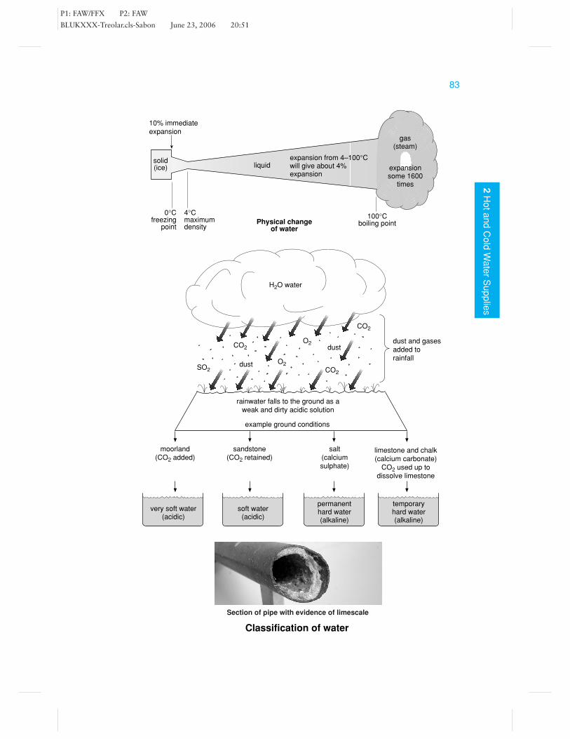
Pure water is a transparent, tasteless liquid which can be found in three physicalstates: solid (ice), liquid (water) or gas (steam or vapour). At atmospheric pressure,between 0 to 100◦C, water is a liquid. At 0◦C, water changes to ice with an immediateexpansion in volume of 10%. At 100◦C, it changes to steam, its volume expandingsome 1600 times.
To convert water back to its constituent elements, an electric current needs to bepassed through the liquid.
Rain water is usually contaminated with gases or chemicals which it absorbed as itfell. When rainwater reaches the ground it dissolves any soluble salts. Depending onwhich salts the water contains it may be classified as hard or soft.
Soft waterThis is water which is free from dissolved calcium salts. Naturally occurring softwater is slightly acidic due to absorbed gases such as CO2. Soft water tends to bemore pleasant for washing in but has the major disadvantage of corroding pipework,lead pipes in particular.
Hard waterThis is water which has fallen on, and filtered through chalk or limestone from whichit dissolves small amounts of calcium and magnesium salts. The water may be eitherpermanently or temporarily hard.
Permanent hardness This is the result of water containing calcium or magnesiumsulphates. Boiling has no effect on permanent hardness.
Temporary hardness This is the result of the water containing calcium or mag-nesium hydrogen carbonates. The CO2 dissolved in rainwater can attack limestoneor chalk and convert the calcium carbonate and magnesium carbonate in the rockto soluble hydrogen carbonates. This temporary hardness can be removed by boilingthe water; as a result CO2 escapes into the air and calcium carbonate is precipitatedas scale.
P1: FAW/FFX P2: FAW
BLUKXXX-Treolar.cls-Sabon June 23, 2006 20:51
832
Ho
ta
nd
Co
ldW
ate
rS
up
plie
s
Classification of water
moorland(CO2 added)
10% immediateexpansion
solid(ice)
0°Cfreezing
point
4°Cmaximumdensity
Physical changeof water
100°Cboiling point
gas(steam)
expansionsome 1600
times
expansion from 4–100°Cwill give about 4%expansion
rainwater falls to the ground as aweak and dirty acidic solution
example ground conditions
sandstone(CO2 retained)
salt(calciumsulphate)
limestone and chalk(calcium carbonate)
CO2 used up todissolve limestone
temporaryhard water(alkaline)
permanenthard water(alkaline)
soft water(acidic)
very soft water(acidic)
dust and gasesadded torainfall
CO2
CO2
SO2
O2
O2
CO2
dust
dust
H2O water
liquid
Section of pipe with evidence of limescale

P1: FAW/FFX P2: FAW
BLUKXXX-Treolar.cls-Sabon June 23, 2006 20:51
84
2H
ot
an
dC
old
Wa
ter
Su
pp
lies
Cold Water to the ConsumerRelevant British StandardsBS EN 806-2 and BS 6700
Throughout the United Kingdom, wholesome water (i.e. water fit for human con-sumption) is provided by the local water authorities to individual premises and var-ious industries. When a supply of water is required, the water authority will supplywater to a point just outside the property boundary line where, nowadays, a meteris usually installed to calculate the amount of water consumed. From this point thesupply pipe is run into the premises, with precautions being taken to protect the pipefrom movement, frost damage and corrosive soil.
Any pipe passing through or under a building must be ducted. This allows for itsremoval should the need arise. A consumer’s stop tap is fitted where the supplypipe enters the building and should be fixed as low as possible with a drain-off cockimmediately above it. (Note that older properties do not have meters.) The pipe is runfrom this point to feed the various systems of cold water supply. It is the responsibilityof the installer to comply with the Water Supply Regulations 1999 when connectingto the supply main. These regulations have been designed in order to prevent wastage,contamination and erroneous measurement of water.
Wastage of water This could be the result of undue consumption, misuse or simplya faulty component, such as a leaking valve. To prevent this, water meters are beinginstalled to register the amount of water used in serving the premises, for which theowner/occupier will eventually be invoiced. As a means of combating the problemof wastage, the installer must provide the dwelling with suitable overflow/warningpipes from cisterns to let the user know of a fault, and a means of isolation mustbe provided to allow its speedy shutdown. Allowance for thermal movement, frostprotection, etc., must be made in order to prevent damage.
Water contamination The Water Supply Regulations include a list of five ‘fluidcategories’ to identify the quality or condition of water, ranging from wholesome (fitfor human consumption) to a level which presents a serious health risk. In very basicterms, the Regulations seek to ensure that once water has been drawn off for use, itshould never be allowed to re-enter the water supply distribution network. There areseveral means by which water may be inadvertently contaminated. For example, itis possible that water may be sucked up from sanitary appliances (back-siphonage),such as baths and sinks, owing to peak flow demands creating a negative pressure onthe supply pipe.
Contamination can also result from the use of unsuitable materials. Lead, for instance,is dissolved by water and as a result its use is prohibited nowadays. Even the solderused to join copper pipes, when used for hot or cold supplies, must be lead-free.
Erroneous measurement This refers to the discrepancy between the measurementor metering of water used and the quantity of water actually accounted and paid for.

P1: FAW/FFX P2: FAW
BLUKXXX-Treolar.cls-Sabon June 23, 2006 20:51
852
Ho
ta
nd
Co
ldW
ate
rS
up
plie
s
Cold water to the consumer
WATER
boundarywall
meter just in oroutside the boundary
water meter
doc
stop valve
750 mm–1350 mm
pipe duct
750 mm minimumotherwise pipeis to be insulated
supply pipecommunication pipe
mains services
gooseneck
meter
Cold supply to a dwelling
‘plan view’ of pipe in trench, note pipe laid withslack to allow for ground movement
Typical water meter
Hose connected to a tap without backflow protection(causing possible contamination)
Frost damage to valve(causing wastage of water)

P1: FAW/FFX P2: FAW
BLUKXXX-Treolar.cls-Sabon June 23, 2006 20:51
86
2H
ot
an
dC
old
Wa
ter
Su
pp
lies
Backflow Prevention
Backflow is a flow of water contrary to the intended direction of water flow. It canbe caused due to back pressure or back siphonage.
� Back pressure is the result of water pressure in the system being greater than thatin the supply. Higher system pressures can be caused by the expansion of water inunvented dhw supplies, or in systems where a pump is used.
� Back siphonage occurs as the result of negative pressures in the supply main, whichmay be caused by a major leak in the main or the fire services drawing off vastamounts of water.
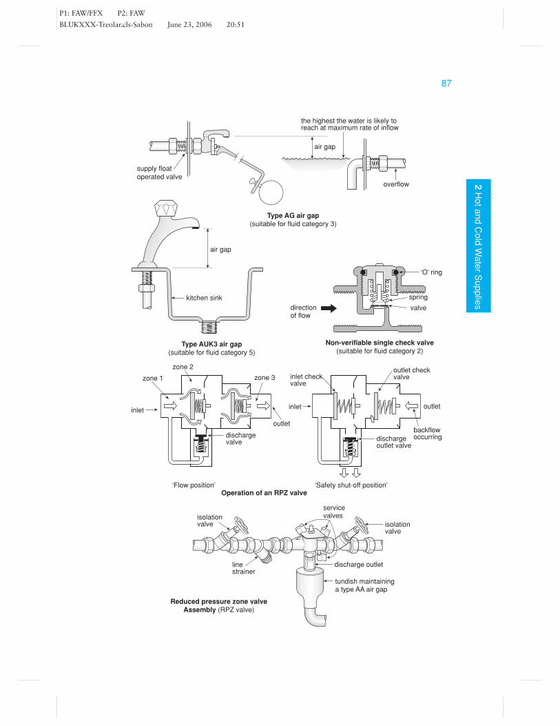
Backflow prevention is achieved either by using a mechanical device or by a pipearrangement which physically disconnects the supply from the system, maintainingan air gap. There are various backflow prevention devices, including single and doublecheckvalves and anti-vacuum valves. The Water Regulations list no less that 10 air gapconfigurations and 14 mechanical device combinations to combat the many scenarioswhere backflow could occur. The method selected would depend upon the severity ofthe risk; this is based upon the fluid risk category of the water that may be affected.
Fluid risk categories Schedule 1 of the Water Supply Regulations identifies fivefluid categories:
Category 1: No health risk. Wholesome drinking waterCategory 2: Aesthetic quality is impaired due to, for example, being heatedCategory 3: Slight health hazard due to contamination with substances of low toxicityCategory 4: Significant health hazard due to toxic substances, e.g. pesticidesCategory 5: Serious health risk. Contains pathogenic organisms, e.g. from human
waste.
Verifiable and non-verifiable checkvalves Where a checkvalve incorporates atest point it is referred to as a verifiable check valve. A single check valve would besuitable where the fluid risk is only category 2. However for fluid risk 3, a doublecheck valve would be required.
Reduced pressure zone valve (RPZ valve) This is a comparatively new valve tothe UK and is used to protect against fluid risk 4 applications, such as a fire sprinklersystem filled with antifreeze in a commercial premises. It can only be installed by anaccredited installer, approved by the water supplier. It should be tested for correctoperation every year, with a test certificate issued. It should be noted that no drinkingwater should be drawn off downstream of the RPZ valve. It sometimes creates a dropin pressure and therefore is not suited to low pressure supplies.
Shown opposite are a few examples of backflow prevention methods, including airgaps and mechanical devices identifying the fluid risk they are suited to.
P1: FAW/FFX P2: FAW
BLUKXXX-Treolar.cls-Sabon June 23, 2006 20:51
872
Ho
ta
nd
Co
ldW
ate
rS
up
plie
s
‘O’ ring
spring
valvedirectionof flow
Non-verifiable single check valve(suitable for fluid category 2)
inlet
zone 1
zone 2
zone 3
outlet
dischargevalve
inlet outlet
dischargeoutlet valve
outlet checkvalveinlet check
valve
the highest the water is likely toreach at maximum rate of inflow
Type AG air gap(suitable for fluid category 3)
overflow
air gap
supply floatoperated valve
Type AUK3 air gap(suitable for fluid category 5)
air gap
kitchen sink
Reduced pressure zone valveAssembly (RPZ valve)
discharge outlet
tundish maintaininga type AA air gap
isolationvalve
servicevalves
linestrainer
isolationvalve
‘Flow position’ ‘Safety shut-off position’Operation of an RPZ valve
backflowoccurring

P1: FAW/FFX P2: FAW
BLUKXXX-Treolar.cls-Sabon June 23, 2006 20:51
88
2H
ot
an
dC
old
Wa
ter
Su
pp
lies
Cold Water SystemsRelevant British StandardsBS EN 806-2 and BS 6700
Two distinct systems of cold water supply are in use – the direct and indirect systems –although modified systems are to be found, in which several appliances are on themains supply and several fed from a cistern. It is essential that the plumber obtainsadvice and gives written notice of the design of a new system to the local waterauthority before commencing work. Failure to do this may mean a contravention ofthe Water Supply Regulations 1999. Whatever system is chosen, it must be designedto deliver cold water at the point of use at a temperature not exceeding 25◦C.
Direct systemIn this system, all the cold water in the house is fed ‘directly’ from the supply main. Thewater pressure is usually high at all outlets, so this system can have the disadvantageof being more prone to water hammer. In some areas of the UK the supply pressure isreduced at peak times. This can cause a negative pressure in the pipeline and loss ofsupply. Also, precautions need to be taken to prevent back-siphonage of foul waterfrom appliances into the supply pipe.
The direct system is cheaper to install than the indirect, and does not require a roofspace to accommodate the cistern. However, peak flow times must be consideredand, above all, adequately sized pipes used to prevent a lack of suitable flow, shouldseveral appliances be used at once.
Indirect systemIn this system, only one draw-off point (i.e. the kitchen sink) is fed from the mainssupply pipe. All other outlets are supplied via a cold storage cistern, usually located inthe roof space. Water pressure is usually much lower than with the direct system, butit will be maintained, even at peak times or during complete shutdown of the supply.Today in modern housing, with suitable precautions to storage cistern sizing andthe prevention of water contamination, stored water is regarded as wholesome (fitfor human consumption) so water from draw-off points other than the mains one isregarded as drinking water and, therefore, the same precautions must be maintainedto prevent back-siphonage.
Cold supply to the domestic hot water (dhw) systemUnvented systems These systems are fed directly from the mains supply pipe.The biggest consideration is whether the supply main is large enough in diameter toprovide a good flow rate should several appliances be operated at once. To preventthe hot water flowing back down the feed pipe, a check valve must be incorporated(see Unvented Domestic Hot Water Supply, page 106).
Vented systems These require a supply via a cold feed cistern. The cold feed pipeis run separately from any cold distribution pipework to prevent hot water beingdrawn off when the cold supply is opened.

P1: FAW/FFX P2: FAW
BLUKXXX-Treolar.cls-Sabon June 23, 2006 20:51
892
Ho
ta
nd
Co
ldW
ate
rS
up
plie
s
cistern
cold feed to dhw
OR
cold supply tounvented system
of dhw
22 mm22 mm
bath
15 mm
basin15 mmWC
22 mm
basinsinkwashingmachine WC
Direct system of cold water supply
dhwstoragevessel
dhwstoragevessel
servicevalve
feed and storagecistern
cold feed to dhw(vented system)22–28 mmfullway
gatevalveor ballvalve
doc
doc
WC15 mm
15 mmbasin
22 mmbath
22 mm
doc
stop valve
Indirect system of cold water supply
Cold water systems
basinwashingmachinesink
cold distribution22–28 mm
supply main
WC
servicevalve

P1: FAW/FFX P2: FAW
BLUKXXX-Treolar.cls-Sabon June 23, 2006 20:51
90
2H
ot
an
dC
old
Wa
ter
Su
pp
lies
Cold Water StorageRelevant British StandardsBS EN 806-2 and BS 6700
When cold water needs to be stored to supply an indirect system of cold water, or tofeed a system of dhw, it is held in a cistern which is usually located in the roof space.
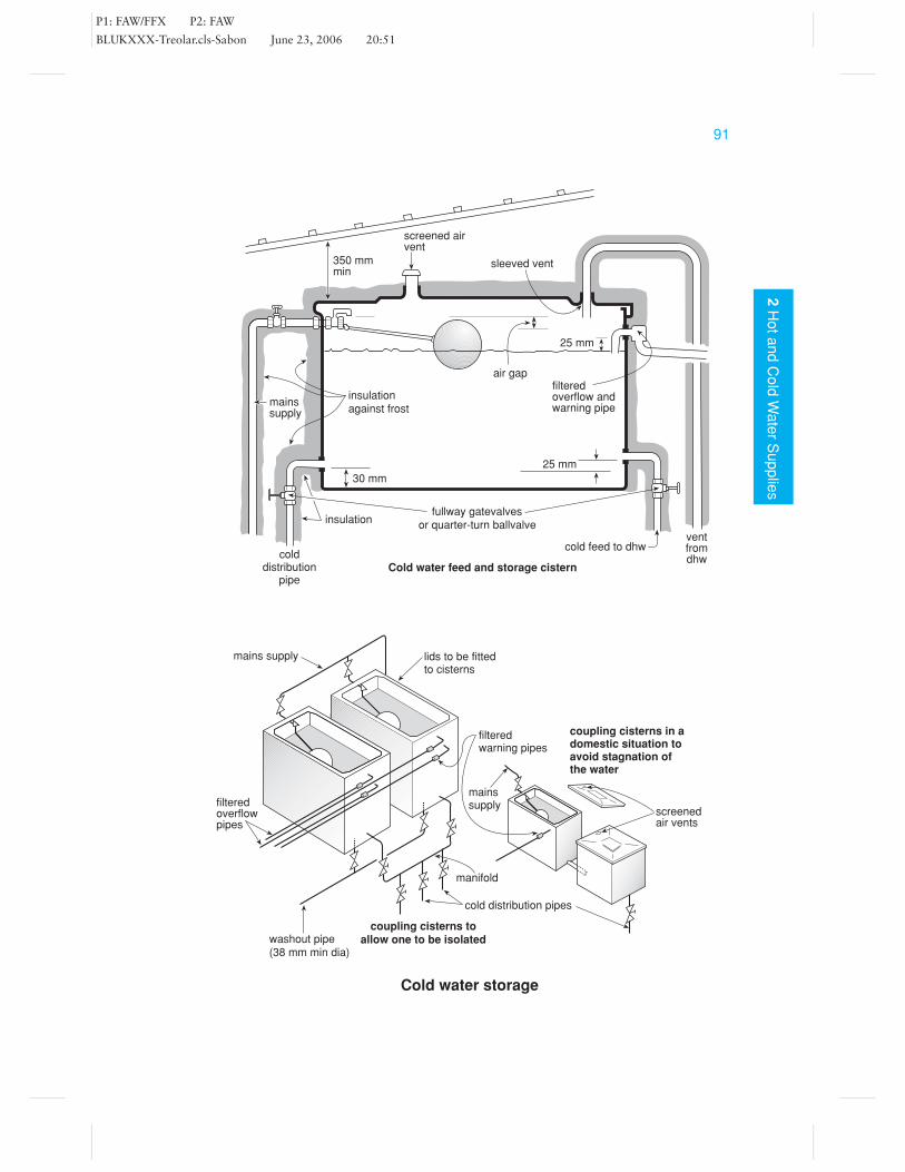
The storage cistern should have a minimum capacity of 100 litres. If the cistern isalso to act as a feed cistern for the hot water supply (being a combined storage andfeed cistern), it should have a minimum capacity of 230 litres.
Cold distribution pipes from storage cisterns should be connected so that the low-est point of the water outlet is a minimum of 30 mm above the base of the cistern. Thisis to prevent sediment passing into the pipework. Connections of feed pipes to hotwater apparatus from cisterns should be at least 25 mm above cold distribution pipes,if applicable. This should minimise the risk of scalding should the cistern run dry.
The float-operated valve (ballvalve) is fitted as high as possible and must com-ply with BS 1212, parts 2 or 3, thus maintaining an air gap and preventing back-siphonage. Overflow pipes should have a minimum internal diameter of 19 mm andin all cases be greater in size than the inlet pipe.
To prevent the ingress of insects, a tight-fitting lid must be provided, with a screenedair inlet. Where a vent pipe passes through the lid, the pipe must be sleeved. Overflowwarning pipes must also incorporate a filter or screen. Finally, the whole installation(cistern and pipes) must be insulated to prevent freezing.
Coupling of storage cisternsIn larger commercial properties it is desirable to have two or more cisterns coupledtogether instead of one large cistern. This is beneficial because one of them can beisolated and drained down, if required. Equally, on a smaller scale, lack of space ina house sometimes limits the size of a storage cistern. In such a case, two smallercisterns can be joined together to give the required capacity. Different methods areused for the above examples. If the need arises to isolate one cistern, an isolatingvalve is fitted at each point in or out of the cistern, which can be shut off. For thepurposes of a domestic house, it would be uncommon for one cistern to be isolated,so the mains supply is usually taken into one cistern and the cold distribution or feedpipe is taken out of the other. By designing it in this way the water in the secondcistern would not become stagnant.
The washout pipe shown in the figure is only used on large cisterns (those holdingover 2300 litres), for the purpose of draining down and cleaning out any sludgedeposits, etc.
Cold supplies to be kept below 25◦CThe Water Supply Regulations state that no cold water supplies should be warmedabove 25◦C. This requirement is to ensure water is not drawn off and wasted, butalso reduces the growth of bacteria such as Legionella. Critical temperatures arebetween 25◦ and 50◦C; therefore it may be necessary to insulate pipes to preventthem becoming too warm due to heat gain.
P1: FAW/FFX P2: FAW
BLUKXXX-Treolar.cls-Sabon June 23, 2006 20:51
912
Ho
ta
nd
Co
ldW
ate
rS
up
plie
s
coupling cisterns toallow one to be isolated
Cold water storage
cold distribution pipes
manifold
filteredwarning pipes
lids to be fittedto cisterns
mains supply
coupling cisterns in adomestic situation toavoid stagnation ofthe water
washout pipe(38 mm min dia)
filteredoverflowpipes
25 mm
30 mm
25 mm
cold feed to dhwventfromdhw
fullway gatevalvesor quarter-turn ballvalve
air gap
sleeved vent
screened airvent
350 mmmin
insulationagainst frost
mainssupply
Cold water feed and storage cisterncold
distributionpipe
filteredoverflow andwarning pipe
screenedair vents
mainssupply
insulation

P1: FAW/FFX P2: FAW
BLUKXXX-Treolar.cls-Sabon June 23, 2006 20:51
92
2H
ot
an
dC
old
Wa
ter
Su
pp
lies
Water TreatmentRelevant British Standard
BS 7593
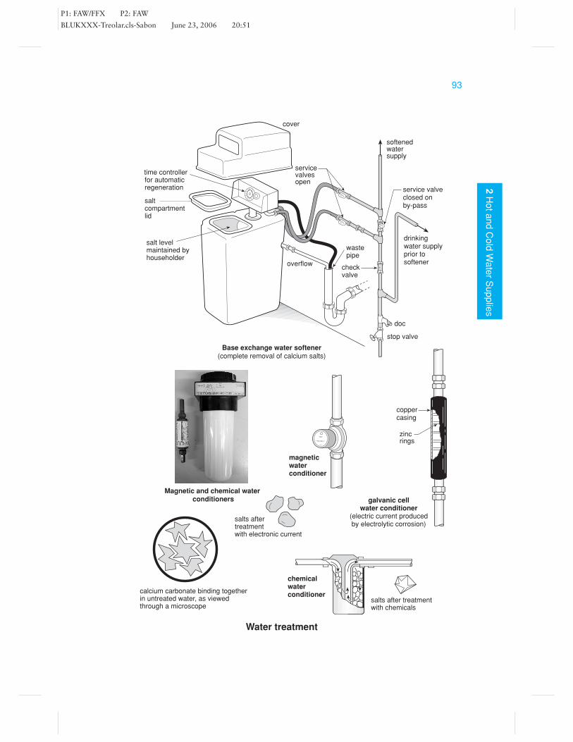
Before water is supplied to the consumer it is treated and purified by the waterauthority. When it arrives at the supply point, usually no more treatment is required.However, in hard water areas, where there are varying amounts of calcium salts in thewater, it is sometimes desirable to treat the water to prevent excessive scale problemsor provide a better liquid with which to wash (e.g. a laundry). The installation of awater softener or a water conditioner fulfils this purpose.
Water softenersThese soften hard water by passing it through a pressure vessel containing zeolites or aresin which absorbs the calcium in the water. After time, the zeolites become exhaustedbecause they become saturated with calcium; they thus need to be regenerated withcommon salt. This is done automatically, by a system of backwashing which is timedto operate at around 3 am via a timeclock or flow metering system, thus causing noinconvenience to the householder. Before installing the softener inlet connection, abranch pipe should be taken from the mains to provide a hard water drinking supply.
The installation of a water softener is quite straightforward, the connections beingmade in the way shown in the figure.
Water conditionersWater conditioners do not soften water, they just stabilise the calcium salts whichare held in suspension. There are two basic types of water conditioner: those thatuse chemicals and those that pass water through an electric or magnetic field. Thecalcium salts, if viewed through a microscope, appear star-shaped, and it is in thisform that they can bind together.
Chemical water conditioners use polyphosphonate crystals. These dissolve in the coldwater and bind to the star-shaped salts, making them circular. These polyphosphonatecrystals are placed in the storage cistern or into specially designed containers fittedinto the pipeline. Periodically the crystals must be replaced.
Electronic and magnetic water conditioners are devices fitted in the pipeline whichpass a low current of a few milliamperes of electricity across the flow of water. Thistends to alter the structure of the hard salts, making them more round or solid inshape and therefore they do not stick together but should pass through the system.Electronic and magnetic water conditioners should be installed as close as possible tothe incoming main supply. Some types of electronic conditioners are plugged into themains electric supply, whereas others rely on the current produced by electrolysis.
P1: FAW/FFX P2: FAW
BLUKXXX-Treolar.cls-Sabon June 23, 2006 20:51
932
Ho
ta
nd
Co
ldW
ate
rS
up
plie
s
Water treatment
salts after treatmentwith chemicals
chemicalwaterconditioner
drinkingwater supplyprior tosoftener
checkvalve
wastepipe
overflow
doc
stop valve
service valveclosed onby-pass
servicevalvesopen
cover
saltcompartmentlid
salt levelmaintained byhouseholder
time controllerfor automaticregeneration
softenedwatersupply
Base exchange water softener(complete removal of calcium salts)
galvanic cellwater conditioner
(electric current producedby electrolytic corrosion)
salts aftertreatmentwith electronic current
magneticwaterconditioner
coppercasing
zincrings
calcium carbonate binding togetherin untreated water, as viewedthrough a microscope
Magnetic and chemical water conditioners
P1: FAW/FFX P2: FAW
BLUKXXX-Treolar.cls-Sabon June 23, 2006 20:51
94
2H
ot
an
dC
old
Wa
ter
Su
pp
lies
Boosted Water SuppliesRelevant British StandardsBS EN 806-2 and BS 6700
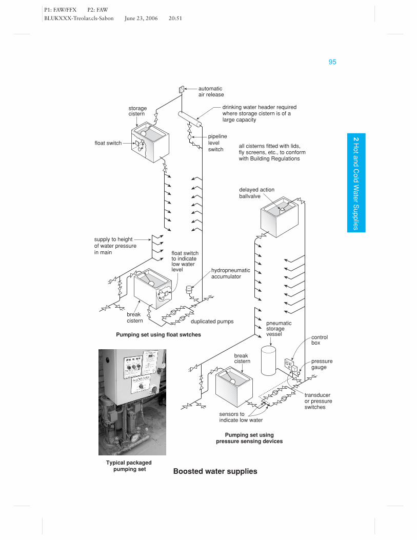
There are two reasons why water may need to be boosted: (1) to give a better flow andpressure at the draw-off point in a domestic situation (see page 118, Connections toHot and Cold Pipework); or (2) as a method of raising the water supply in high-risebuildings above the height that the mains will supply.
The pumps are usually fitted indirectly to the supply main. If fitted directly, a seriousdrop in the mains pressure may occur when the pumps are running. The indirectsystem consists of a suitably sized break cistern located at the inlet to the pumpingset (see figure). Nowadays, ‘packaged’ pumping sets are installed consisting of dualpumps to overcome the problem of failure of (or the need to renew) one of thepumps. The second pump also assists at times of high demand on the system, cuttingin as necessary. To prevent pump seizure and stagnation of water, the pumps shouldbe designed to work alternately. Two types of system will be found: those usingpressure-sensing devices and those using float switches.
Pressure-sensing devices These include transducers or pressure switches whichsense the drop in pressure in the pipeline. These come fitted to, and form part of, thepackaged pumping set. To prevent the continuous cutting in and out of the pumps, adelayed action ballvalve or float switch is used in the high level cisterns. If draw-offpoints are required on the riser, a pressurised pneumatic storage vessel is sometimesincorporated to prevent the continual cutting in and out of the pumps; this consistsof a vessel containing a rubber bag surrounded by a charge of air. When the pumpsare running, water can enter and fill the bag, taking up volume and compressing theair. When the pumps are turned off, the compressed air forces the water back outinto the pipeline, as and when required.
Float switches These are devices which rise and fall with the water level. Theyare therefore located in cisterns or pipelines to sense a drop or lack of water withinthe system. If the high level cistern is of large capacity, it may be necessary to havea drinking water header to prevent stagnation, or a separate high level cistern fordrinking water purposes.
To prevent the pumps running dry for any reason, a sensing device needs to beincorporated in the pipe feeding the pumps, e.g. an in-line sensor or a float switchfitted in the break cistern.
Water hammer can be a problem when fitting pumps to any system. Therefore ahydropneumatic accumulator should be incorporated if necessary. Packaged pumpingsets incorporate these as standard. They are basically small pressurised pneumaticvessels, the air taking up the shock wave (for example see page 129).
P1: FAW/FFX P2: FAW
BLUKXXX-Treolar.cls-Sabon June 23, 2006 20:51
952
Ho
ta
nd
Co
ldW
ate
rS
up
plie
s
Boosted water supplies
float switch
storagecistern
pipelinelevelswitch
automaticair release
drinking water header requiredwhere storage cistern is of alarge capacity
all cisterns fitted with lids,fly screens, etc., to conformwith Building Regulations
delayed actionballvalve
supply to heightof water pressurein main float switch
to indicatelow waterlevel hydropneumatic
accumulator
duplicated pumps
breakcistern
Pumping set using float swtches
transduceror pressureswitches
Pumping set usingpressure sensing devices
pressuregauge
controlbox
sensors toindicate low water
breakcistern
pneumaticstoragevessel
Typical packaged pumping set

P1: FAW/FFX P2: FAW
BLUKXXX-Treolar.cls-Sabon June 23, 2006 20:51
96
2H
ot
an
dC
old
Wa
ter
Su
pp
lies
Fire-fighting SystemsRelevant British Standards
BS 4422 and BS 5306
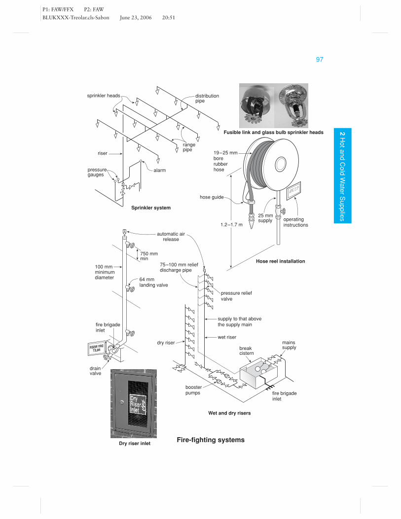
Sprinkler systemsOn the outbreak of fire, a sprinkler system causes an automatic discharge of waterto be sprayed, usually from sprinkler heads located near the ceiling. See the figureopposite for a typical arrangement for the pipe layout. See also page 98, Domesticsprinkler systems. In commercial premises, as distinguished below, there are two basicdesigns:
� The wet-pipe system, in which the sprinkler system is permanently charged withwater.
� The dry-pipe system, in which the sprinkler system is charged with compressed airand is used in unheated buildings where the temperature may fall below 0◦C. Ifthey were to be charged with water these pipes would be liable to freeze.
The operating principle of a sprinkler head is that when the temperature around thehead rises to a predetermined level, either a water filled glass bulb breaks, or a solderstrut melts, allowing the valve to fall and open.
Hose reel systemsWhen hose reels are used, they should be sited in prominent positions adjacent toexits, so that the hose can be taken to within 6 metres of any fire. Two basic designsof hose reels are available: those which automatically turn on as the hose is reeledout, and those which need to be turned on at the wall. For the latter type, a noticemust be provided near the reel indicating the need to turn on the supply. The hosereel must be adequate to supply a minimum of 0.4 litres per second.
The water supplies feeding sprinkler systems and hose reels need to be adequate (seeparticularly BS 5306); they are usually maintained via a system of boosted watersupply.
Wet and dry risersThese systems are for the use of the fire brigade and consist of pipes, (100–150 mmin diameter) running up the building with one or two fire brigade hydrants on eachfloor. The purpose of this pipe is to save time running canvas hoses up the staircasesshould the building be on fire. The dry pipe system is used in buildings up to 60 metresin height (20 storeys) and is fitted with an inlet at ground level for the fire brigade toconnect to the nearest hydrant. The wet riser is used in taller buildings because themains pressure would be insufficient to rise to such great heights, and is charged withwater under pressure by a booster pump capable of delivering 23 litres/s. The waterpressure supplied to the hydrants should not exceed 690 kN/m2, otherwise damagemay occur to the hose. Therefore, a pressure relief valve is fitted at the hydrant; thisopens if the pressure is too great, the discharging water returning to the break cistern.
P1: FAW/FFX P2: FAW
BLUKXXX-Treolar.cls-Sabon June 23, 2006 20:51
972
Ho
ta
nd
Co
ldW
ate
rS
up
plie
s
Fire-fighting systems
pressuregauges
riser
alarm
sprinkler heads
rangepipe
distributionpipe
Sprinkler system
mainssupplybreak
cistern
wet riser
supply to that abovethe supply main
pressure reliefvalve
75–100 mm reliefdischarge pipe
automatic airrelease
Wet and dry risers
fire brigadeinlet
boosterpumps
dry riser
19–25 mmborerubberhose
hose guide
25 mmsupply operating
instructions
Hose reel installation
64 mmlanding valve
750 mmmin
100 mmminimumdiameter
DRY RISERINLET
fire brigadeinlet
drainvalve
1.2–1.7 m
Fusible link and glass bulb sprinkler heads
Dry riser inlet

P1: FAW/FFX P2: FAW
BLUKXXX-Treolar.cls-Sabon June 23, 2006 20:51
98
2H
ot
an
dC
old
Wa
ter
Su
pp
lies
Domestic Sprinkler Systems
Domestic sprinkler systems are relatively rare in the UK, but are becoming more andmore sought after as a means of protection in the event of a fire. Used in conjunctionwith a smoke detector they are said to provide 98% protection. Should a fire breakout in the home, the longer it burns undetected the more dangerous it becomes. Mostpeople who discover a fire in the home do so too late and as a result many are trapped.The installation of a domestic sprinkler system should only be undertaken by anoperative who has completed a recognised training course in design and installation.Water damage will clearly result from the activation of a sprinkler head, however itis approximately one hundred times less damage than could be expected from thefire services at a well-established fire. When considering the installation of a sprinklersystem the local fire authority, water company and the fire insurer should be consulted.
Water suppliesOne of the first things to consider is the water supply pressure and flow. It is vitalthat sufficient flow and pressure are available at the sprinkler head at all times, bothuninterrupted and reliable. Failure to meet these basic requirements would meanthe system is unsuitable. Good water flow is essential to meet the needs of coolingthe combustible materials below their ignition temperature and a good pressure isneeded to create an effective water spray for the sprinkler head. The water supplyneeds to maintain the manufacturer’s required flow and pressure when dischargingthrough two sprinkler heads at the same time. At least 60 L/min is required throughany single sprinkler head, and 42 L/min through any two sprinklers operating atthe same time. This would usually require the incoming supply pipe to be at least25 mm nominal internal diameter. The water may be provided from a direct mainsconnection providing there is sufficient supply to provide both the domestic waterand sprinkler system together plus an additional flow rate of 50 L/min. It is possibleto have a system that incorporates a demand valve that closes off the domestic watersupply should the sprinkler system be activated. Alternatively, a separate dedicatedwater supply would be needed for the sprinkler system. This could be via a secondmains connection or by the use of a stored water supply. Where a stored supply isselected there must be sufficient storage to provide the minimum recommended flowand pressure by the sprinkler head manufacturer for a period of at least 10 minutes.
Sprinkler headsThese need to be of a design that is suitable for residential use. They need to beinstalled throughout all the habitable parts of the dwelling, each head covering notmore than 12 m2. The sizes available give a nominal diameter at the orifice outletof between 10 and 20 mm. The temperature ratings for individual heads is given inthe table opposite; the head selected should allow for 30◦C above highest anticipatedambient temperature.

P1: FAW/FFX P2: FAW
BLUKXXX-Treolar.cls-Sabon June 23, 2006 20:51
992
Ho
ta
nd
Co
ldW
ate
rS
up
plie
s
BSP thread12
housing
valve plug
glass bulb
Typical glass bulb sprinkler head
Sprinklertype
Temperaturerange (°C)
Colourcode
55–77
80–107
57
68
79
93
None
White
Orange
Red
Yellow
Green
Fusible link
Glass bulb
Sprinkler temperature ratings
Domestic sprinkler system
to domesticdraw-off points
supplymains
quarter-turnfullway valve
flow switch(to prevent false alarmdue to surge)
checkvalve
stopvalve
12 V demandvalve
ground floorsprinklers
1st floor sprinklers
sprinklersin loft
plug
quarter-turn fullway valve(for air elimination andtest puposes)
deflector
drainvalve
drain valve
P1: FAW/FFX P2: FAW
BLUKXXX-Treolar.cls-Sabon June 23, 2006 20:51
100
2H
ot
an
dC
old
Wa
ter
Su
pp
lies
Hot Water Systems(Design Considerations)
Relevant British StandardsBS EN 806-2 and BS 6700
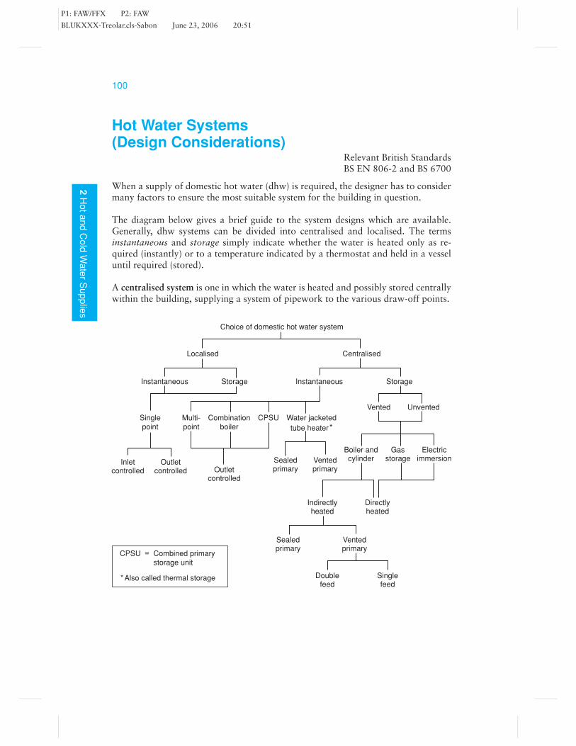
When a supply of domestic hot water (dhw) is required, the designer has to considermany factors to ensure the most suitable system for the building in question.
The diagram below gives a brief guide to the system designs which are available.Generally, dhw systems can be divided into centralised and localised. The termsinstantaneous and storage simply indicate whether the water is heated only as re-quired (instantly) or to a temperature indicated by a thermostat and held in a vesseluntil required (stored).
A centralised system is one in which the water is heated and possibly stored centrallywithin the building, supplying a system of pipework to the various draw-off points.
Choice of domestic hot water system
Localised Centralised
Instantaneous Storage Instantaneous Storage
Singlepoint
Multi-point
Combinationboiler
CPSU Water jacketed
tube heater*
Vented Unvented
Sealedprimary
Ventedprimary
Boiler andcylinder
Gasstorage
Electricimmersion
Indirectlyheated
Directlyheated
Sealedprimary
Ventedprimary
Doublefeed
Singlefeed
Outletcontrolled
Inletcontrolled Outlet
controlled
CPSU = Combined primarystorage unit
* Also called thermal storage

P1: FAW/FFX P2: FAW
BLUKXXX-Treolar.cls-Sabon June 23, 2006 20:51
1012
Ho
ta
nd
Co
ldW
ate
rS
up
plie
s
A localised system is one in which the water is heated locally to its needs, e.g. asingle-point heater located above a sink. It may be chosen where a long distributionpipe would mean an unnecessarily long wait for hot water to be drawn off at theappliance.
In a centralised system, the water may be heated in the hot storage vessel itself, orit may be heated in a boiler or small gas circulator located in a more convenientposition. Should this be the case, the water is fed to and from the boiler by what areknown as primary flow and return pipes. The circulation of water can be achievedby convection currents being set up in the flow and return pipework, or by the useof a circulating pump. Water flows by convection currents as a result of expandingin volume when heated; modern systems utilising gas or oil boilers would require apumped circulation system.
When water is heated it becomes less dense than cooler water. Because hot water rises,it is drawn off from the top of the storage vessel to supply the various draw-off points(taps). The cold feed is supplied low down in the vessel, thus preventing unnecessarycooling to the previously heated water. At the highest point in the system, a vent pipeis run up to terminate, with an open end just below the feed cistern lid. This pipe is toallow air to escape from the system upon initial filling and allows air in on drainingdown.
The vent pipe also acts as a fail-safe device should the cold feed become blocked,preventing the expanding water passing back up into the cistern. Should this occur,the water is forced over the vent and discharges into the cistern. The height to whicha vent pipe is to rise above the water level in the cold cistern is found by allowing40 mm for every 1m head of water in the system, plus an additional 150 mm. Forexample, if the distance between the lowest point in the system and the water levelin a cistern is 5 m, the vent pipe should be carried up above the water level by aminimum distance of: 5 × 40 + 150 = 350 mm.
The temperature at which the water is stored in the cylinder should not exceed 60◦C.Failure to observe this limit may result in the user being scalded and scale build-up in hard water districts. Storage temperatures below 60◦C are concerning as theLegionella bacteria survival time increases as the temperature drops below 60◦C.At 60◦C the bacteria is killed within a few minutes. Some means of controlling thetemperature should therefore be provided. When a primary circuit is used with anindependent boiler, the temperature is generally controlled by a cylinder thermostatpositioned a third of the way up the base of the dhw cylinder operating a motorisedvalve; however, for older systems the water temperature may be controlled by a boilerthermostat or a thermostatic control valve located on the return pipe.
These last two temperature control methods would no longer comply with the Build-ing Regulations where an oil or gas boiler is installed.
P1: FAW/FFX P2: FAW
BLUKXXX-Treolar.cls-Sabon June 23, 2006 20:51
102
2H
ot
an
dC
old
Wa
ter
Su
pp
lies
Direct Hot Water Supply (Centralised)Relevant British Standards
BS EN 806-2, BS 5546 and BS 6700
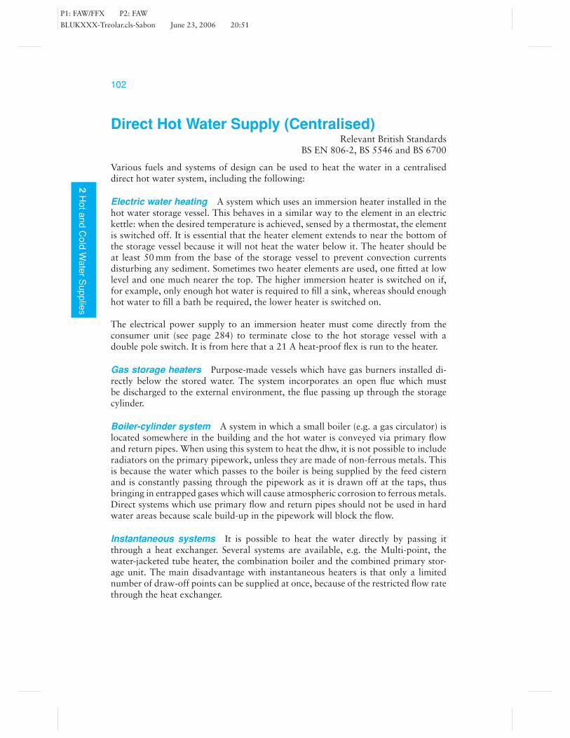
Various fuels and systems of design can be used to heat the water in a centraliseddirect hot water system, including the following:
Electric water heating A system which uses an immersion heater installed in thehot water storage vessel. This behaves in a similar way to the element in an electrickettle: when the desired temperature is achieved, sensed by a thermostat, the elementis switched off. It is essential that the heater element extends to near the bottom ofthe storage vessel because it will not heat the water below it. The heater should beat least 50 mm from the base of the storage vessel to prevent convection currentsdisturbing any sediment. Sometimes two heater elements are used, one fitted at lowlevel and one much nearer the top. The higher immersion heater is switched on if,for example, only enough hot water is required to fill a sink, whereas should enoughhot water to fill a bath be required, the lower heater is switched on.
The electrical power supply to an immersion heater must come directly from theconsumer unit (see page 284) to terminate close to the hot storage vessel with adouble pole switch. It is from here that a 21 A heat-proof flex is run to the heater.
Gas storage heaters Purpose-made vessels which have gas burners installed di-rectly below the stored water. The system incorporates an open flue which mustbe discharged to the external environment, the flue passing up through the storagecylinder.
Boiler-cylinder system A system in which a small boiler (e.g. a gas circulator) islocated somewhere in the building and the hot water is conveyed via primary flowand return pipes. When using this system to heat the dhw, it is not possible to includeradiators on the primary pipework, unless they are made of non-ferrous metals. Thisis because the water which passes to the boiler is being supplied by the feed cisternand is constantly passing through the pipework as it is drawn off at the taps, thusbringing in entrapped gases which will cause atmospheric corrosion to ferrous metals.Direct systems which use primary flow and return pipes should not be used in hardwater areas because scale build-up in the pipework will block the flow.
Instantaneous systems It is possible to heat the water directly by passing itthrough a heat exchanger. Several systems are available, e.g. the Multi-point, thewater-jacketed tube heater, the combination boiler and the combined primary stor-age unit. The main disadvantage with instantaneous heaters is that only a limitednumber of draw-off points can be supplied at once, because of the restricted flow ratethrough the heat exchanger.

P1: FAW/FFX P2: FAW
BLUKXXX-Treolar.cls-Sabon June 23, 2006 20:51
1032
Ho
ta
nd
Co
ldW
ate
rS
up
plie
s
immersion heater
flue
draughtdiverter
Gas storage heater
magnesiumanode
cold inlet
dippedcold feed
gassupply
vent pipe
hot distributionpipe
baffle in flue
burner
Section through gas storage heater
sink
doc
Note: it is possible to have anunvented system of directdhw supply
Direct hot water supply
boiler
g.v. or quarter-turn valve
vented system shown in which thewater is heated either via a boiler, anelectric immersion heater or gascirculator
bath basin
sink
doc
thermostat
20 ampheatproof flex
Instantaneoussystem(multi-point)
Direct dhw cylinder(no heat exchanger coil)
Multi-point heater with the case removed
P1: FAW/FFX P2: FAW
BLUKXXX-Treolar.cls-Sabon June 23, 2006 20:51
104
2H
ot
an
dC
old
Wa
ter
Su
pp
lies
Indirect Hot Water SupplyRelevant British Standards
BS EN 806-2, BS 5546 and BS 6700
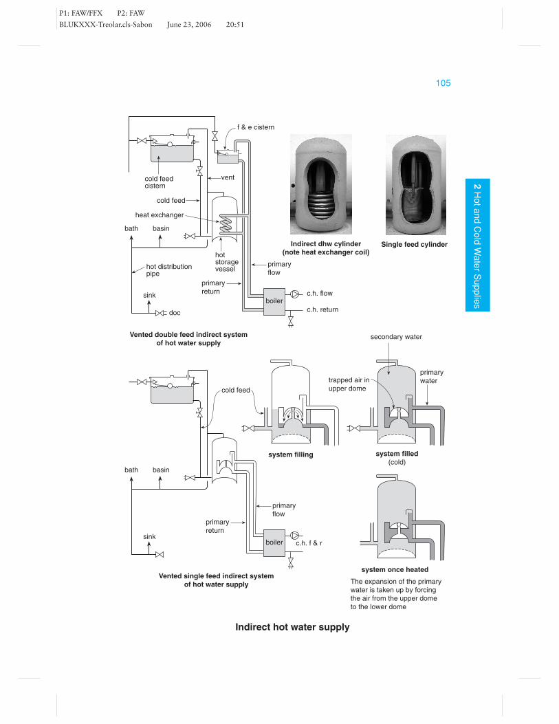
The indirect dhw system is probably the most common form of dhw and allows aboiler to be used for central heating purposes also. The storage vessel is the heart ofthese systems and consists of a special cylinder in which is fitted a heat exchanger.The heat exchanger allows water from the boiler circulating in the primary pipeworkto pass through, but not mix with, the water in the cylinder itself. Thus, in effect, itreally consists of two systems which appear to join at the hot storage vessel.
Water is heated in the boiler and conveyed to the hot storage vessel via primaryflow and return pipes by the use of a circulating pump; older systems utilised gravitycirculation (convection currents). The water supplying this primary circuit can betaken from the f & e cistern, which is usually located in the roof space, or directlyfrom the supply main in the case of a sealed system (see Part 3, Central Heating).The water, once in the primary pipework, is never changed except for maintenancepurposes. Therefore, any calcium carbonate (limescale) will have been precipitatedand any gases which came in with the fresh supply will have escaped from the water.Thus, the water in this state is somewhat neutralised; it will not cause excessivecorrosion of steel radiators and is suitable for central heating purposes.
Because the primary water must not be changed, the water supply for domestic pur-poses needs to be taken from a separate supply, and, if using a feed cistern in the roofspace, it must be separate from the f & e cistern to prevent mixing of the waters ineach system.
As we have seen, most indirect systems are of the double feed design, using twocisterns in the roof space, and having a coil or annulus type heat exchanger fitted intothe cylinder. But there is a second older type, known as a single feed indirect system(the design in the figure opposite being known as the Primatic). This system used aspecially designed heat exchanger which allowed the primary circuit to fill up via abuilt-in feed pipe. In so doing it maintained an air break separating the primary andsecondary waters.
The figure shows how the expansion of the water in the primary circuit is takenup by moving the air in the top dome back through its cold feed pipe to the lowerdome. The primary circulation system must not be too large (having many radiators)because the excessive quantity of water that the system will contain would, whenexpanding, exceed that of the space available in the dome, thus forcing the air out.Also, a circulating pump must not be used on the primary circuit to the dhw cylinderfor the same reason. Should the air be lost, the space would be filled instead withwater and it would be converted, in effect, into a direct system of hot water supply;this would give rise to corrosion problems.
P1: FAW/FFX P2: FAW
BLUKXXX-Treolar.cls-Sabon June 23, 2006 20:51
1052
Ho
ta
nd
Co
ldW
ate
rS
up
plie
s
Indirect hot water supply
boiler
bath basin
sink
doc
cold feedcistern
cold feed
f & e cistern
vent
hotstoragevessel
primary
return
hot distributionpipe
Vented double feed indirect systemof hot water supply
primary
flow
c.h. flow
c.h. return
boiler
bath basin
sink
primary
return
Vented single feed indirect systemof hot water supply
primary
flow
c.h. f & r
cold feed
system filling
secondary water
primary
watertrapped air in
upper dome
system once heated
system filled(cold)
The expansion of the primary
water is taken up by forcing
the air from the upper dome
to the lower dome
heat exchanger
Indirect dhw cylinder(note heat exchanger coil)
Single feed cylinder

P1: FAW/FFX P2: FAW
BLUKXXX-Treolar.cls-Sabon June 23, 2006 20:51
106
2H
ot
an
dC
old
Wa
ter
Su
pp
lies
Unvented Domestic Hot Water SupplyRelevant British StandardsBS EN 806-2 and BS 6700
When considering the installation of a system of unvented dhw (stored supply inexcess of 15 litres), Part G of the Building Regulations should be observed. This iden-tifies several requirements to be met by the local authority. Systems must be installedby an ‘approved’ installer who is registered with a recognised body and the systemmust be purchased as a unit or package. From April 2006, systems installed need tobe self-certificated in order to meet the requirement of Part G.
A unit is a system in which all the component parts have been fitted by themanufacturer at the factory. A package is a system in which the temperature-activatedcontrols are incorporated but all other components are fitted by the installer. In bothcases this ensures that the safety devices, which are ‘factory set’, are installed with thesystem. The Regulations state that at no time must the water reach 100◦C, which isensured by the use of three safety devices: the thermostat (operating at 60◦C); a hightemperature thermal cut-out device (which locks out at 90◦C); and a temperaturerelief valve (designed to open at 95◦C).
With unvented systems the water is taken directly from the mains water supply.There is no open vent pipe or storage cistern where the expansion of heated watercan be taken up. Therefore some form of expansion vessel needs to be incorporated.To comply with water regulations, a check-valve must be fitted on the supply pipeto prevent a backflow of hot water down the supply main. Should the expansionvessel not function for any reason, the water, on expanding, will be forced out of thepressure relief valve.
Any water discharging from either a temperature relief valve or pressure relief valvemust be conveyed, via an air break, to a suitable discharge position. The dischargepipe must not exceed 9 m in length and the pipe diameter of the discharge outlet mustbe maintained. A pressure-reducing valve is fitted as a precaution to reduce excessivewater pressures which may cause damage to the system. In order to ensure equalpressures at both hot and cold draw-off points, the cold supply pipe is sometimesbranched off after this valve.
The advantages of these systems are the higher pressures obtainable at the draw-offpoints, the use of less pipework and the fact that less time is required for installa-tion. The disadvantages are frequently overlooked. First, such a system can only beinstalled should the flow rate (volume of water) be sufficient to supply both hot andcold water at once, bearing in mind that several appliances could be running at thesame time. Second, in hard water districts, the build up of scale around temperatureand pressure relief valves could make those valves ineffective. Regular servicing ofthe system is therefore essential.
Some unvented dhw cylinders use a sealed expansion vessel to take up the ex-panding water. Others incorporate an inverted dome which traps a pocket of air, thusdoing away with the need for a sealed expansion vessel. Unfortunately, high waterturbulence within the cylinder sometimes causes the air trap to be lost, although onemanufacturer has overcome this problem by using a floating baffle to cut down onturbulence. After a period of time the air may be absorbed into the water renderingthe dome ineffective, resulting in the pressure relief valve opening. Consequently thecylinder will need draining down to recharge the dome with air.

P1: FAW/FFX P2: FAW
BLUKXXX-Treolar.cls-Sabon June 23, 2006 20:51
1072
Ho
ta
nd
Co
ldW
ate
rS
up
plie
s
Unvented domestic hot water supply
Check valve
Pressurereducing valve
floatingbaffle
tundishand airgap
dischargepipe
test lever
Combined pressureand temperaturerelief valve
Unvented system incorporating an air pocket
mains watersupply
Unvented systemincorporatingexpansion vessel and primarycircuit
As the water
cools the air
pressure forces
the water out of
the bag back
into the system
rubber bag
containing the
expanding water
point to check
and charge up
the pressure
to discharge
pipe
test lever
high
temperature
cut out
temperature
relief valve
stop valvemains
water
supply
Sealed expansion vessel(system heated therefore
bag shown full)
Strainer
immersion with high
temperature cut out
Pressure reliefvalve
Unvented system using expansion vessel
Unvented system using a floating baffle
Selection of control valves found on unvented system

P1: FAW/FFX P2: FAW
BLUKXXX-Treolar.cls-Sabon June 23, 2006 20:51
108
2H
ot
an
dC
old
Wa
ter
Su
pp
lies
Hot Distribution PipeworkRelevant British StandardsBS EN 806-2 and BS 6700
The hot water in the storage vessel needs to be preserved for as long as possible to saveon fuel consumption. The cylinder and pipework should therefore be insulated. How-ever, hot water can also be lost due to the circulatory flow of hot water, by convectioncurrents, up the vertical vent pipe. To prevent this, the hot distribution should be runa minimum of 450 mm horizontally on leaving the top of the hot storage vessel.
When a tap is opened, before the hot water can discharge from the spout, thecold water in the pipe has to be drawn off and is invariably allowed to run to waste.This also causes a certain amount of inconvenience to the user. Where possible thesystem should be designed to provide a temperature of no less than 50◦C within 30s,although this may not be achievable where instantaneous or combination boilers areused. The run of pipe to the appliance is referred to as a ‘dead leg’ and should, wherepossible, not exceed that indicated in the following table.
Maximum length of uninsulated hot distribution pipe
Internal bore of pipe (mm) Length (m)
less than 10 2011–19 1220–25 8Over 26 3
Where it is not possible to keep within these limits, the pipe should be thermallyinsulated, or some other method should be used to ensure that the hot water appearsquickly at the tap. Either of two methods can be adopted to meet this requirement:a specially designed heat tracing tape can be used, which heats up as necessary,maintaining the water temperature; or a system of secondary circulation will need tobe installed.
Secondary circulation An arrangement in which a pipe is run back to the dhwcylinder from the furthest point on the distribution, thus forming a circuit. Watercan flow around this circuit usually by the use of a non-corrosive circulating pump,thus allowing hot water to be kept close to the draw-off points. The return pipe isconnected within the top third of the cylinder to prevent the cooler water, lower downthe cylinder, mixing with the hot water and reducing its temperature.
Hydraulic gradient When a tap is opened and water drawn from the system, thewater level in any vertical pipe will drop. The amount by which it drops will dependon the size of the pipework and the flow rate being drawn off (see figure). In anycistern-fed system, be it hot or cold, if the pipework is less than perfect, when severalappliances are running at once, one will be starved of water (usually the highest draw-off point). This is due to the above-mentioned drop in water level in the vertical pipe.
When installing a system of hot water supply, it is particularly important to con-sider this design concept, because any high connections in the vertical rise of the ventpipe will be starved of water unnecessarily.

P1: FAW/FFX P2: FAW
BLUKXXX-Treolar.cls-Sabon June 23, 2006 20:51
1092
Ho
ta
nd
Co
ldW
ate
rS
up
plie
s
Hot distribution pipework
open ventpipe
hotdistributionpipe
450 mm
correct(incorporating a450 mm offset inthe rise of vent)
incorrectone pipe circulation
taking place
pump
bath basin
secondaryflow
basin
Connections to the top ofthe hot storage cylinder
secondaryreturn
sink
Secondary circulation
water at a state of rest with a ‘no flow’ conditionwater flowing from
valve when tap opened
drop inwaterlevels
hydraulicgradient
‘X’
hydraulicgradient correct
connectionof tap
Illustration to identify the hydraulic gradient
All taps opened and a ‘no flow’ situation is indicated at tap ‘X’(tap ‘X’ will only operate providing no other taps are open)
P1: FAW/FFX P2: FAW
BLUKXXX-Treolar.cls-Sabon June 23, 2006 20:51
110
2H
ot
an
dC
old
Wa
ter
Su
pp
lies
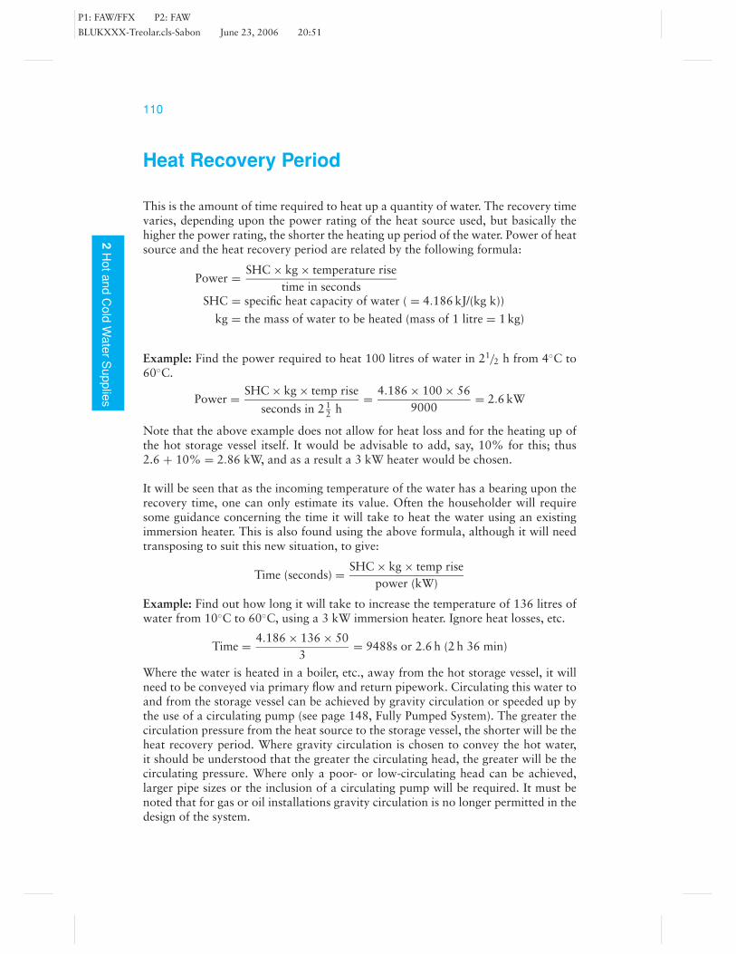
Heat Recovery Period
This is the amount of time required to heat up a quantity of water. The recovery timevaries, depending upon the power rating of the heat source used, but basically thehigher the power rating, the shorter the heating up period of the water. Power of heatsource and the heat recovery period are related by the following formula:
Power = SHC × kg × temperature risetime in seconds
SHC = specific heat capacity of water ( = 4.186 kJ/(kg k))
kg = the mass of water to be heated (mass of 1 litre = 1 kg)
Example: Find the power required to heat 100 litres of water in 21/2 h from 4◦C to60◦C.
Power = SHC × kg × temp rise
seconds in 2 12 h
= 4.186 × 100 × 569000
= 2.6 kW
Note that the above example does not allow for heat loss and for the heating up ofthe hot storage vessel itself. It would be advisable to add, say, 10% for this; thus2.6 + 10% = 2.86 kW, and as a result a 3 kW heater would be chosen.
It will be seen that as the incoming temperature of the water has a bearing upon therecovery time, one can only estimate its value. Often the householder will requiresome guidance concerning the time it will take to heat the water using an existingimmersion heater. This is also found using the above formula, although it will needtransposing to suit this new situation, to give:
Time (seconds) = SHC × kg × temp risepower (kW)
Example: Find out how long it will take to increase the temperature of 136 litres ofwater from 10◦C to 60◦C, using a 3 kW immersion heater. Ignore heat losses, etc.
Time = 4.186 × 136 × 503
= 9488s or 2.6 h (2 h 36 min)
Where the water is heated in a boiler, etc., away from the hot storage vessel, it willneed to be conveyed via primary flow and return pipework. Circulating this water toand from the storage vessel can be achieved by gravity circulation or speeded up bythe use of a circulating pump (see page 148, Fully Pumped System). The greater thecirculation pressure from the heat source to the storage vessel, the shorter will be theheat recovery period. Where gravity circulation is chosen to convey the hot water,it should be understood that the greater the circulating head, the greater will be thecirculating pressure. Where only a poor- or low-circulating head can be achieved,larger pipe sizes or the inclusion of a circulating pump will be required. It must benoted that for gas or oil installations gravity circulation is no longer permitted in thedesign of the system.

P1: FAW/FFX P2: FAW
BLUKXXX-Treolar.cls-Sabon June 23, 2006 20:51
1112
Ho
ta
nd
Co
ldW
ate
rS
up
plie
s
Heat recovery period
boiler
circulatinghead
poor heat recovery(say 3 h)
boiler
good heat recovery(say 2 h)
circulatinghead
primaryflow
Rough comparison of time takento warm water in cylinder basedon a 17 kW boiler and a 136 litredhw storage vessel
hot storagecylinder
primaryreturn
excellent heat recovery(say 1/2 h)
boiler
pump
The heat recovery period is also influenced by the design and dhw cylinder used. Allmodern systems use BS 1566 cylinders. These have no less than 5–6 turns within theheat exchanger coil and the cylinder includes factory-fitted insulation foam. Highperformance cylinders can also be purchased with an even greater number of coils.The following chart shows the number of boiler cycles and approximate time requiredto raise a typical 136 litre cylinder up to the required temperature.
Fully
pumped
systems
High performance cylinder
Current BS 1566 cylinder
Old BS 1566 cylinder
Medium duty cylinder ongravity circulation
0 10 20 30 40 50 60 70 80 90 100
larger heat exchangers reduce
boiler cycling and the recovery
period
boiler cycles
Recovery time (minutes)
High performance cylinder(note the many coils to
provide rapid heat recovery)

P1: FAW/FFX P2: FAW
BLUKXXX-Treolar.cls-Sabon June 23, 2006 20:51
112
2H
ot
an
dC
old
Wa
ter
Su
pp
lies
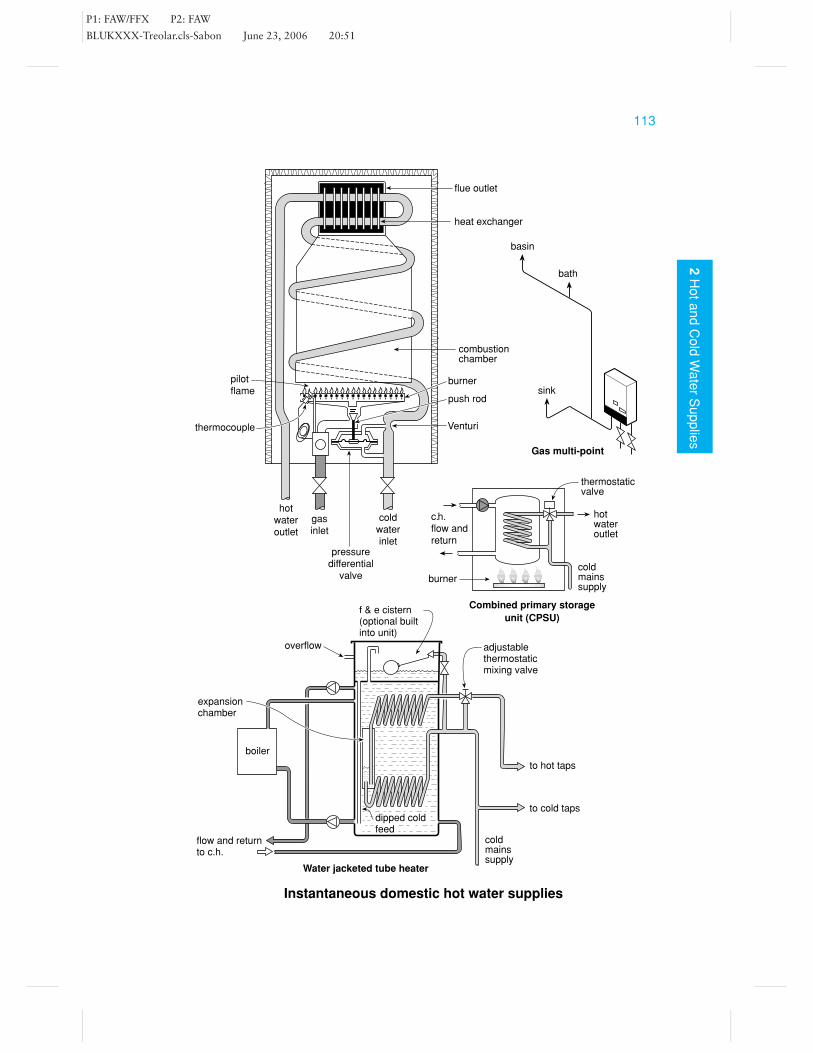
Instantaneous Domestic Hot Water Supplies(Centralised)
Relevant British StandardsBS EN 806-2, BS 5546 and BS 6700
With instantaneous dhw systems, the principle is to pass the cold water through aheat exchanger, such as a coil of pipework passing through a heat source, whichheats the water by the time it comes out the other end. There is a limit to the speedat which the water can be heated; therefore, the flow rate (volume) of water needs tobe minimised; failure to minimise the flow rate will result in an insufficient heat-up.Because of this reduced flow rate of water passing through the heat exchanger it isnot possible to supply several outlets at once; as a result these systems are unsuitablewhere there is to be high demand for hot water. With these systems you only heat thewater as and when it is required; therefore, a saving can be made in fuel consumption.Instantaneous heaters include multi-points, water-jacketed tube heaters, CPSUs andcombination boilers. (See page 154 for combination boilers.)
The multi-point This consists of a gas burner located beneath a heat exchanger.When hot water is required, the water, in passing through the heater, causes the gasvalve to open, and this is ignited by a pilot flame. The gas valve opens as the result of areduction in the water pressure on one side of a diaphragm in the pressure differentialvalve caused by water passing through a Venturi. Attached to the diaphragm is thepush rod which opens the gas line. On shutting the water supply, the pressure inthe differential valve equalises and the diaphragm is sprung shut, closing off the gassupply.
The water-jacketed tube heater Sometimes referred to as a thermal storage sys-tem, this is a system in which the water to be heated is passed through a stored supplyof central heating water. It is like an indirect system of dhw in reverse; the domes-tic water flows through the heat exchanger and not the primary water. One end isconnected to the cold supply main, the other directly to the taps. When the wateris heated, a small amount of expansion occurs and is taken up in a small expansionvessel located in the cold supply line fitted to the unit or within the unit itself via anexpansion chamber. Because the water in the heat exchanger can potentially becomeas hot as the water in the primary storage cylinder, it must be noted that water, uponleaving the unit, passes through a thermostatic mixing valve in which the water iscooled from the cold supply to give a temperature no hotter than 60◦C.
The combined primary storage unit (CPSU) This system of instantaneous dhwis the same as a water-jacketed tube heater, the only difference being that everythingis contained within the boiler and no separate hot water storage vessel is required.
P1: FAW/FFX P2: FAW
BLUKXXX-Treolar.cls-Sabon June 23, 2006 20:51
1132
Ho
ta
nd
Co
ldW
ate
rS
up
plie
s
flue outlet
heat exchanger
pilotflame
thermocouple
hotwateroutlet
gasinlet
coldwaterinlet
pressuredifferential
valve
Venturi
push rod
combustionchamber
bath
sink
Gas multi-point
basin
Instantaneous domestic hot water supplies
to hot taps
to cold taps
adjustablethermostaticmixing valve
dipped coldfeed
Water jacketed tube heater
flow and returnto c.h.
boiler
expansionchamber
f & e cistern(optional builtinto unit)
coldmainssupply
thermostaticvalve
c.h.flow andreturn
hotwateroutlet
coldmainssupply
burner
Combined primary storageunit (CPSU)
burner
overflow
P1: FAW/FFX P2: FAW
BLUKXXX-Treolar.cls-Sabon June 23, 2006 20:51
114
2H
ot
an
dC
old
Wa
ter
Su
pp
lies
Localised Hot Water HeatersRelevant British Standards
BS EN 806-2, BS 5546 and BS 6700
Two distinct types of localised dhw heaters will be found: the instantaneous andstorage types. In each case the heater will serve only one sink, or two if fitted in closeproximity to the heater.
Instantaneous single pointsThese heaters are fuelled either by gas or electricity and heat the water only whenrequired. They are usually fitted with a swivel spout and located directly above thesanitary appliance, the water flow usually being inlet controlled. The gas heater workson the same principle as the multi-point (see page 112).
With electric instantaneous heaters, the water is allowed to flow into the heater,where it is surrounded by an electric heating element. Because of the small volume ofwater surrounding the element, the water quickly heats up as it is drawn through theheater. The temperature of the water will be directly related to the power rating ofthe appliance and the water flow rate. The water flowing through the heater is sensedby the pressure or flow switch located on the inlet supply, which in turn makes theelectrical contacts to the immersion heater element.
Storage type single pointsThese heaters are located either above or below a sink or similar appliance and have acapacity not exceeding 15 litres. The stored water is heated by an electric element to,for example, 60◦C, and on expanding the water is allowed to push up and dischargefrom the discharge spout. It is important to make the client aware of this drippingspout. When cold water enters the base of the unit it forces the hot stored water out.Obviously the discharge of hot water is limited and will soon start to cool, but it willbe sufficient for small quantities of draw-off. When installing these heaters belowan appliance, a special design of terminal fitting (tap) needs to be used – one whichallows water to flow through the heater but at the same time allows the water toexpand (see figure).
Some designs of single points incorporate a small expansion vessel which enables anoutlet control valve to be used, eliminating dripping outlet spouts.

P1: FAW/FFX P2: FAW
BLUKXXX-Treolar.cls-Sabon June 23, 2006 20:51
1152
Ho
ta
nd
Co
ldW
ate
rS
up
plie
s
Localised hot water heaters
permanentlyopen hotsupply and vent
coldsupplyto tap
coldsupply
to heater
specialised design of tap to allow forthe expansion of water from thestorage heater when installedbelow the appliance
section through an electricinstantaneous water heater
electricalsupply
electricalelement
inlet
section through an electricsingle point storage water heater
inletcontrolled
immersionheater
thermostat
hot outlet asused aboveon appliance
outletcontrolled
Single point gas water heater
View inside a small electric single point heater

P1: FAW/FFX P2: FAW
BLUKXXX-Treolar.cls-Sabon June 23, 2006 20:51
116
2H
ot
an
dC
old
Wa
ter
Su
pp
lies
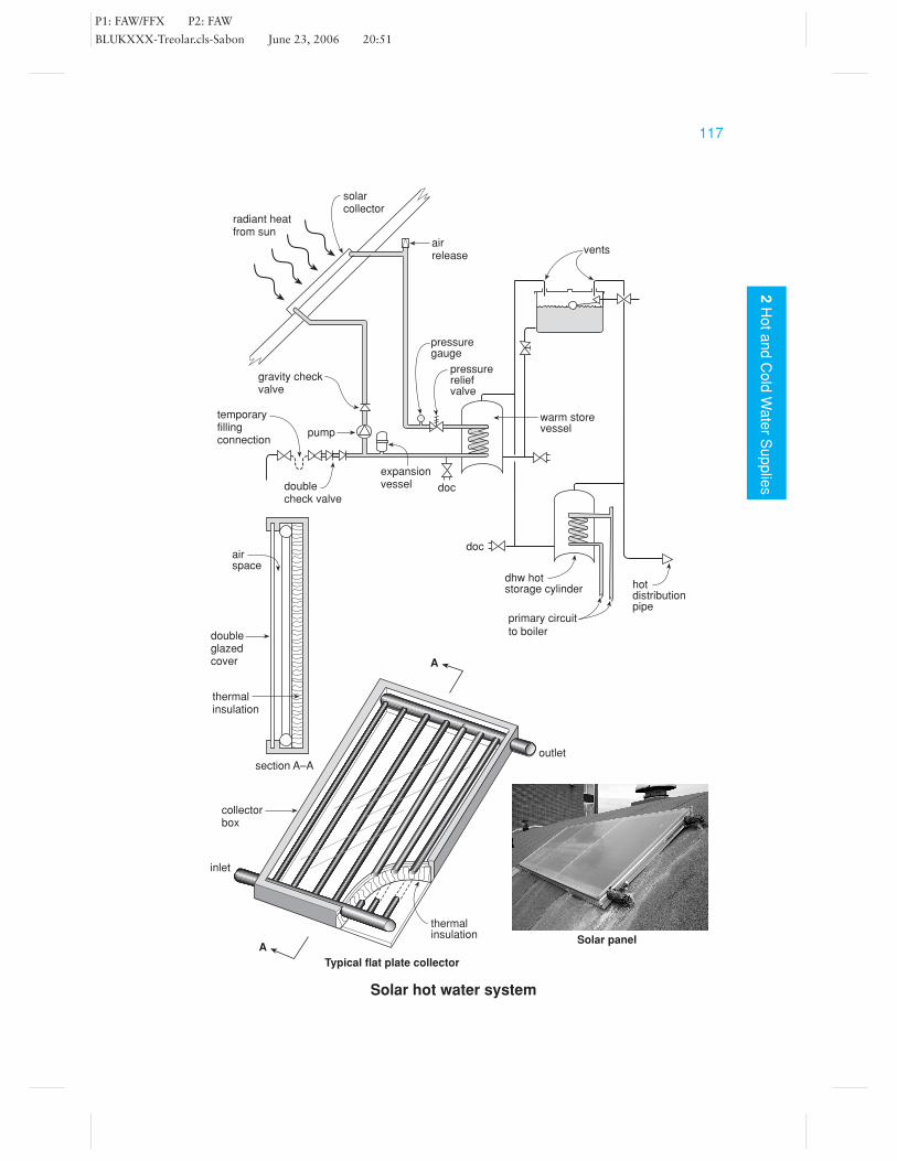
Solar Hot Water SystemRelevant British Standard
BS 5918
This is a dhw system which utilises energy from the sun. It collects the radiant heatwaves in a solar collector, usually located on the roof. A simple solar collector consistsof a thin vessel painted matt black with piping attached flowing to and from a hotstorage vessel. It is covered with double- or triple-glazing and backed by thermalinsulation material. The collector is sited at a convenient position to catch the solarheat, usually at an angle of 40◦ and facing south.
Designs of solar heating systems can vary, and because of the unreliable weatherin the UK, would not be used in any dwelling as the only form of heating for water.Generally, cold water is supplied to a warm store vessel which is heated by solarenergy; the water then passes onto the normal conventional hot storage cylinder andis supplied with additional heat (if required) by a boiler or electric immersion heater.Note that in the system shown opposite, the solar collector is fitted above the cold feedcistern. This causes no problems because the primary circuit from the solar collectorforms part of a closed system. The water in the primary circuit is made to circulateby means of a pump which is switched on automatically should the temperature inthe top of the collector be higher than that in the base of the hot storage vessel.However, it is possible to design a gravity system, providing the collector can belocated sufficiently far below the warm store vessel to allow circulation to take place.
Thermal performance Based on a long-term average temperature in London, thesystem should supply an approximate percentage of that indicated in the followingtable. However, the amount of solar energy supplied to the dhw system will varyfrom area to area, and will depend upon the effectiveness of the solar collector andits location. It should be remembered that trees and buildings casting shade willsignificantly reduce system performance.
Approximate monthly percentage for solar heating system, in theLondon area, on a south facing 30◦ pitched roof
% %
January 2 July 13
February 5 August 13
March 6 September 12
April 10 October 8
May 12 November 4
June 13 December 2
Design considerations Due to temperature changes, the temperature of the heattransfer liquid could vary from about −15◦C to as high as 200◦C, when not circu-lating; where water is used for this (see figure) it will be necessary to prevent thetemperature from rising above 100◦C by incorporating a pressure relief valve as aminimum requirement, discharging its contents to a safe location. To prevent damagedue to excessively cold conditions, an anti-freeze solution may be added; alternativelythe system will need to be drained in winter. Usually planning permission will needto given by the local authority before a solar heating system can be installed.
P1: FAW/FFX P2: FAW
BLUKXXX-Treolar.cls-Sabon June 23, 2006 20:51
1172
Ho
ta
nd
Co
ldW
ate
rS
up
plie
s
Solar hot water system
radiant heatfrom sun
solarcollector
airrelease
vents
warm storevessel
pressurereliefvalve
pressuregauge
doc
expansionvesseldouble
check valve
temporaryfillingconnection
gravity checkvalve
pump
doc
dhw hotstorage cylinder hot
distributionpipe
primary circuitto boiler
airspace
doubleglazedcover
thermalinsulation
section A–A
A
A
inlet
thermalinsulation
collectorbox
outlet
Typical flat plate collector
Solar panel

P1: FAW/FFX P2: FAW
BLUKXXX-Treolar.cls-Sabon June 23, 2006 20:51
118
2H
ot
an
dC
old
Wa
ter
Su
pp
lies
Connections to Hot and Cold PipeworkRelevant British StandardsBS EN 806-2 and BS 6700
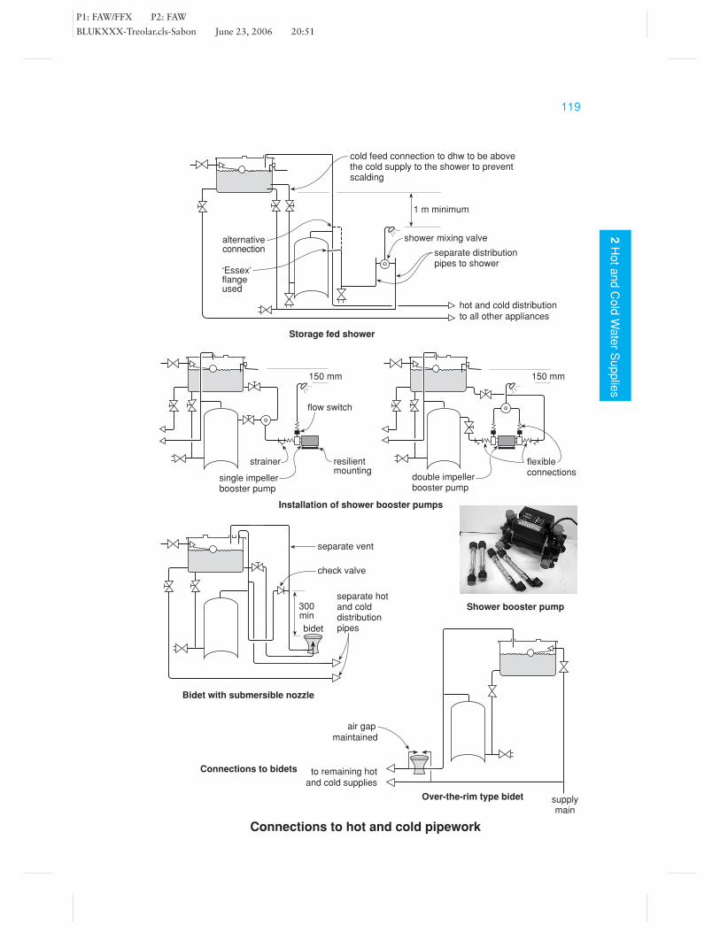
Connections to showersThe hot and cold supplies to a shower will need to be of equal pressure. Wherethe supply is directly from the service main, provision must be made to ensure nobackflow occurs. This is usually achieved by ensuring that the shower head cannotdischarge below the overspill level of the appliance or by incorporating a doublecheck-valve assembly into the pipeline.
Connections via a storage cistern will need to be such that an adequate pressure isachieved; in general, a minimum distance of 1 metre from the underside of the cisternto the shower head should be maintained. The pressure can be increased by the use ofa booster pump fitted into the pipeline in which a small self-contained unit, designedto give a greater head of water, is used. The only proviso is that at least 150 mm ofinitial head is available to allow the flow switch to operate and start the pump whenthe supply is opened.
It is possible to use a flow-activating button where no head at all is available for somedesigns of pump. Booster pumps may be fitted before or after the shower-mixing valve,although in general they should be installed in such a location as to ensure that it isconstantly flooded with water. Where a shower booster which draws more than 12litres/min is considered, the water authority may need to be advised regarding its use.
To ensure that the shower is never starved of water, the cold supply to the showermixing valve should be independent of other draw-off points and its connection tothe storage cistern should be below that of the cold feed to the dhw cylinder.
The temperature of the water to the shower is regulated by means of manual orthermostatic control. With the manually controlled valve, a dial on the control headis turned to open or close either the hot or cold porthole size, thus restricting theflow. Thermostatic mixing valves are fitted with a temperature-sensing device whichis designed to expand due to heat and should maintain a constant outlet temperature,opening or closing the portholes automatically as required.
Connections to bidetsThere are two types of bidet: those with pillar taps to give an over-the-rim typedischarge, thus maintaining an air gap; and those with a submerged nozzle whichdischarges a spray of water upwards from the base of the appliance. Those with anascending spray are not permitted to be connected directly to the supply main andmust have their hot and cold supplies run via separate distribution pipes, independentof other draw-offs. This can be achieved as shown in the figure. Note that a checkvalve and an additional separate vent pipe from the hot distribution pipe to theappliance are required.
P1: FAW/FFX P2: FAW
BLUKXXX-Treolar.cls-Sabon June 23, 2006 20:51
1192
Ho
ta
nd
Co
ldW
ate
rS
up
plie
s
Connections to hot and cold pipework
Installation of shower booster pumps
flow switch
150 mm
strainer
single impellerbooster pump
resilientmounting
150 mm
double impellerbooster pump
flexibleconnections
alternativeconnection
1 m minimum
shower mixing valve
separate distributionpipes to shower
hot and cold distributionto all other appliances
‘Essex’flangeused
cold feed connection to dhw to be abovethe cold supply to the shower to preventscalding
Storage fed shower
Bidet with submersible nozzle
300min
bidet
check valve
separate vent
separate hotand colddistributionpipes
Over-the-rim type bidet
Connections to bidets to remaining hotand cold supplies
air gapmaintained
supplymain
Shower booster pump

P1: FAW/FFX P2: FAW
BLUKXXX-Treolar.cls-Sabon June 23, 2006 20:51
120
2H
ot
an
dC
old
Wa
ter
Su
pp
lies
Installation of Pipework 1Relevant British StandardsBS EN 806-2 and BS 6700
Pipe supportsThere are many designs of pipe support bracket and the one chosen will depend uponthe material nature of the pipe, the cost allowed for the job, and upon circumstances;for example, it would be pointless to use plastic pipe clips in schools or hospitals,etc., where they could very easily be damaged. Whatever pipe support is chosen, thefixing must be secure to prevent damage and the possible development of air locks.As a guide, the general recommended pipe support spacings are given in the followingtable, but one must remember that one clip too many is better than one clip too fewand, in many cases, plumbers have to use their own judgement.
Maximum spacings for internal pipework (m)
Pipe size Copper pipe Steel pipe Plastic pipe
(mm) (in) horizontal vertical horizontal vertical horizontal vertical
15 12
1.2 1.8 1.8 2.4 0.6 1.2
22 34
1.8 2.4 2.4 3.0 0.7 1.4
28 1 1.8 2.4 2.4 3.0 0.8 1.5
35 1 14
2.4 3.0 2.7 3.0 0.8 1.7
42 1 12
2.4 3.0 3.0 3.6 0.9 1.8
54 2 2.7 3.0 3.0 3.6 1.0 2.1
Design considerationsIf the pipe is to run through structural timbers such as floor joists, it is essentialthat the structural members are not weakened. Notches and holes should be as smallas practicable, but should also allow for pipe expansion and contraction. The sizeand position of a notch or hole need to be considered and should not exceed thedimensions in the figure.
Example: For a joist 200 mm deep and 3m long (measured from centre line of thebearing) any notch must have a maximum depth of H ÷ 8
Therefore notch depth 200 ÷ 8 = 25 mm
and be at least 0.07 L from its bearing; therefore 0.07 × 3000 = 210 mmand no greater than L ÷ 4 from its bearing; therefore 3000 ÷ 4 = 750 mm.
In vented systems the pressure is usually quite poor in comparison with mains supplypipework. Therefore, it is essential to run the pipework with no dips or high spots,which may allow a trap of air to form, causing a blockage (air lock). To this end,pipes should be run horizontal, or to an appropriate fall, allowing the air to escapefrom the system.

P1: FAW/FFX P2: FAW
BLUKXXX-Treolar.cls-Sabon June 23, 2006 20:51
1212
Ho
ta
nd
Co
ldW
ate
rS
up
plie
s
Installation of pipework 1
backplate
threadedstudding
double splitmunzing ring
single splitmunzing ring
screw on holderbat(school board clip)
plastic spacing clip
saddle clip
holes to be located in this
zone, drilled centrally and
located not less than
3 diameters apart
two piece spacing clip
Typical pipe supports
H
L4
0.4 L
L
centre of bearing centre of bearing
H8
H8
L4
0.07 L
Common causes of air locks
cistern
complete
air blockage
trapped air
hot storage
cylinder
partial blockage
of trapped air
Selection of typical pipe clips used on copper and steel
pipework
P1: FAW/FFX P2: FAW
BLUKXXX-Treolar.cls-Sabon June 23, 2006 20:51
122
2H
ot
an
dC
old
Wa
ter
Su
pp
lies
Installation of Pipework 2Relevant British Standards
BS EN 806-2 BS 5422 and BS 6700
Thermal insulationWhen installing any pipework, steps need to be taken to prevent the pipe contentsfrom freezing in the case of cold water supplies and losing heat in hot water systems.Therefore, some form of insulation may be required. Insulation materials entrap smallair pockets which are a poor conductor of heat. Should a pipe freeze, damage canoccur to the pipework; therefore, insulation is imperative in exposed locations. Roofspaces and garages must be regarded as exposed. The insulation requirements dependon the thermal conductivity of the insulation material. The following table gives aguide to the minimum insulation for frost protection in housing.
Minimum thickness of insulation material
Indoor installations Outdoor installations(e.g. roof space) (including below ground)
Outside pipe Flexible foam and Flexible foam anddiameter expanded plastic Loose-fill expanded plastic Loose-fill
(mm) (mm) (mm) (mm) (mm)
0–15 22 89 27 10016–22 22 75 27 10023–42 22 75 27 8943–54 16 63 19 75
Flat surfaces 13 38 16 50
It should be noted that smaller pipes require a greater thickness of material becausethey are more prone to freezing up.
Accessibility of pipeworkIt is a water regulation that all water pipes and fittings be readily accessible for in-spection and repair. Often the designer/installer has no wish to see exposed pipework;therefore, a duct or chase is made in the wall, etc., and enclosed by a cover to allowmovement and ease of removal. This cover may be covered at the choice of the clientwith plaster or a tile finish (see figure for examples). Note that thermal insulationmaterial may also be required in exposed or unheated dwellings, although not shownin the examples. It is only possible to encase the pipe in the floor screed where it formspart of a heating element of a closed circuit of under-floor radiant heating.
When passing pipes through floors or walls, the pipe should be sleeved to allowmovement, and the space between the pipe and sleeve ‘fire stopped’ to prevent thepassage of smoke and flame.

P1: FAW/FFX P2: FAW
BLUKXXX-Treolar.cls-Sabon June 23, 2006 20:51
1232
Ho
ta
nd
Co
ldW
ate
rS
up
plie
s
Installation of pipework 2
Pipe passing through a cavity
removable cover floor screed
Pipes below solid floors
concrete base
this method may only be adoptedwhere no joints are enclosed andthe pipe can readily be withdrawn
Pipes under floors
Pipes below timber floorsboards must be removable for inspection ofjoints and in all cases inspection availableat 2 m intervals
pipe screwedto stud withresilientmounting
plaster ortile finish
pipe inchase
only permitted in an internalwall where the pipe can becapped off should a leakbecome apparent
cover
removablecover
Pipes within wallstimber studwall
sleevee.g. largerpipe
insulation(if required)
Pipes located behind a bath
removalcover bath
cover duct

P1: FAW/FFX P2: FAW
BLUKXXX-Treolar.cls-Sabon June 23, 2006 20:51
124
2H
ot
an
dC
old
Wa
ter
Su
pp
lies
Sizing of Hot and Cold PipeworkRelevant British StandardsBS EN 806-2 and BS 6700
For everyday plumbing in a domestic dwelling, the installer uses a rule of thumb (triedand tested) method which consists of 15–22 mm pipe on the supply main and a 22–28 mm pipe for the hot and cold distribution pipework. In each case the larger size ischosen if there are many draw-off points, the pipe slowly reducing in size as necessaryto each appliance. For bigger systems requiring many outlets over a large area orseveral floors, the main distribution pipe run will need to be sized correctly to ensuresufficient pressure and flow at the draw-off points, without excessive noise problems.
Shown opposite is a completed table, which acts as a key to the figure below it.An explanation of the stages carried out to choose the pipe sizes is as follows.
Column 1 This is the pipework which is being sized; note that the system is brokeninto various sections.Column 2 The flow required is found by making an assessment of the probablemaximum demand of water, in litres per second, at any given time, because it isvery unlikely that all the sanitary appliances will be used at once. To perform thisassessment, a method has been devised based upon the theory of probability, in whicha loading unit rating is given to each type of sanitary appliance.
Sanitary appliance Loading unit
WC cistern 2
Bath 10
Wash basin 1 12
Sink and washing machine 3
Shower 3
Bidet 1
By multiplying the number of each type of appliance by its loading unit and addingtogether the results, the total loading units for the system will be found.
To convert loading units to flow rate (litres per second), the conversion tableopposite is used. Thus, in our example, where each floor has one bath, two basinsand two WC cisterns, the number of loading units is:
Bath: 1 × 10 = 10Wash basin: 2 × 1 1
2 = 3WC cistern: 2 × 2 = 4Total: 17 loading units
From the conversion table opposite, 17 loading units gives a flow rate of 0.4 litres/s.Note that for pipe section A all five floors are being served; therefore the total loadingunits for this section will be: 17 × 5 = 85, which converts to a flow rate of 1.1 litres/s.

P1: FAW/FFX P2: FAW
BLUKXXX-Treolar.cls-Sabon June 23, 2006 20:51
1252
Ho
ta
nd
Co
ldW
ate
rS
up
plie
s
Cold distribution pipe serving five flats
1 2 3 4 5 6 7 8 9
Se
ctio
n
Flo
wra
te
Su
gg
este
dp
ipe
siz
e
Ve
locity
Lo
ss
of
he
ad
Effe
ctive
pip
ele
ng
th
Fri
ctio
na
lh
ea
d
Pro
gre
ssiv
eh
ea
d
Actu
alh
ea
d
(I/s) (mm) (m/s) (m) (m) (m) (m) (m) Notes
A 1.1 28 1.8 0.2 × 16.5 = 3.3 3.3 3 UndersizedA 1.1 35 1.25 0.07 × 18.2 = 1.27 1.27 3 �B 0.92 28 1.5 0.15 × 4.5 = 0.68 1.95 6 �C 0.8 22 2.2 0.43 × 4.0 = 1.72 3.67 9 Possible noiseC 0.8 28 1.3 0.12 × 4.5 = 0.54 2.49 9 �D 0.6 22 1.6 0.27 × 4.0 = 1.08 3.57 12 �
Pipe sizing of hot and cold pipework
7 m
2 m
D
C
B
A
basin
bath basin
WC3 m
3 m
3 m
3 m
3 m
cold storagecistern
maindistributionpipe
appliances ateach floor tobe the sameas those onthe highestlevel
500
400
300
200
100
50
20
100.3
0.4
0.5
1.0
1.5
2.0
3.0
4.0
Litre
s p
er
second
Loadin
g u
nits
Conversion table(loading units to litres/sec)
WC

P1: FAW/FFX P2: FAW
BLUKXXX-Treolar.cls-Sabon June 23, 2006 20:51
126
2H
ot
an
dC
old
Wa
ter
Su
pp
lies
Column 3 An assumption is made at this stage that a particular pipe size is correct,and the table will confirm (or reject) its possible use.
Columns 4 and 5 The velocity and loss of head can simply be read from the graphopposite. To use, take a horizontal line from the flow in litres per second to intersectthe pipe diameter; from this point the readings can be taken.
Column 6 The effective length of pipe run is found by adding the actual net lengthof pipe to the length of pipe due to frictional loss.
Equivalent pipe lengths, due to frictional loss through copper fittings
Pipe o.d Elbow Tee Stopcock Check-valve
(mm) (m) (m) (m) (m)
15 0.5 0.6 4.0 2.5
22 0.8 1.0 7.0 4.3
28 1.0 1.5 10.0 5.6
35 1.4 2.0 13.0 6.0
42 1.7 2.5 16.0 7.9
54 2.3 3.5 22.0 11.5
In the example given, the effective length for section A, with an assumed pipe diameterof 28 mm, is:
Actual length = 12.0 mThree elbows = 3.0 m
One tee = 1.5 m
Total = 16.5 m
Column 7 The frictional head is found by multiplying the loss of head by the effectivepipe length (i.e. column 5× Column 6).
Column 8 The progressive head is the sum total of the frictional heads for each sectionabove the section in question.
Example: The progressive head for section C will be sections A + B + C
Therefore 1.27 + 0.68 + 0.54 = 2.49 m
Column 9 The actual head is the total head available; it is standard practice to mea-sure this vertically from the underside of the storage cistern to the end of the sectionof pipe in question.
In conclusion, one estimates a suggested pipe diameter and completes the tablefor the section to prove its suitability for use. The pipe size is correct provided thatthe progressive head does not exceed the actual head and the velocity does not ex-ceed 2 m/s in cold water pipework and 1.5 m/s in dhw systems, thus limiting noisetransmissions.

P1: FAW/FFX P2: FAW
BLUKXXX-Treolar.cls-Sabon June 23, 2006 20:51
1272
Ho
ta
nd
Co
ldW
ate
rS
up
plie
s
Pipe sizing of hot and cold pipework
(Reproduced with permission of The Institute of Plumbing and Heating Engineering)
20
.0
10
.0
5.0
4.0
3.0
2.0
1.0
0.5
0.4
0.3
0.2
0.1
0.0
5 0.0
00
10
.00
02
0.0
00
50
.00
10
.00
20
.00
50
.01
0.0
20
.05
0.0
10
.20
.51
.0
108
mm
76 m
m
54 m
m
42 m
m 35 m
m 28 m
m
22 m
m
15 m
m
5.0
m/s
ec v
eloc
ity
4.0
3.0
2.5
2.0
1.5
1.0
0.75
0.5
Flow rate (litres per second)
Lo
ss o
f h
ea
d (
me
tre
s p
er
me
tre
ru
n)
co
pp
er
an
d p
lastic
pip
e
ve
locity m
/se
c

P1: FAW/FFX P2: FAW
BLUKXXX-Treolar.cls-Sabon June 23, 2006 20:51
128
2H
ot
an
dC
old
Wa
ter
Su
pp
lies
Noise Transmission in PipeworkRelevant British StandardsBS EN 806-2 and BS 6700
Impulsive noise (water hammer)A hammering noise which occurs in high pressure water pipes; the noise is caused bysurges of pressure. There are two basic noise types:
(1) A noise which consists of a sudden loud bang and is often caused by a loosestopcock jumper or washer which quickly flips shut onto the seating. It may,on the other hand, be caused by pipes which have not been fixed correctly andflap about; in which case the noise is caused by sudden back surges of pressure,perhaps created by the rapid closing of a tap.
(2) Oscillation or ballvalve murmur which consists of a series of bangs or rumblesgenerated in the pipeline. The noise is created by a float-operated valve quicklyopening or closing, this being caused by ripples or waves which form on thesurface of the water in a storage cistern. To overcome this problem, a largerballfloat is often used or a damping plate fitted to the float or ballvalve lever arm;alternatively, baffle vanes are fitted in the cistern to prevent waves forming.
One method often employed to cure water hammer is to shut down slightly theincoming stop-valve. This does not reduce the pressure but it reduces the flow rate ofthe water.
Flow noise A general noise caused by the water flowing through the pipework. Ifthe water velocity is kept below 3 m/s in high-pressure pipework and below 2 m/s inlow-pressure pipework, this flow noise will not be significant. Sudden changes of di-rection and minimal downstream pressures can cause cavitation, which is turbulence,causing air bubbles to form and collapse. Flow noise can result unnecessarily whenone uses roller pipe cutters and fails to remove the internal burr.
Pump noise When a booster pump has been provided, noises should not be gen-erated by water pressure and flows, providing the pump is correctly sized. However,the noise of the motor running may give concern, in which case isolation of the pumpfrom the building is the only answer. Noise transmission from pumps can be reducedby using rubber-type connections to the pipework and installing the pump on a re-silient mounting.
In large buildings, excessive water noise problems may be overcome by the instal-lation of a hydropneumatic accumulator. This consists of a rubber bag into whichthe water can enter; the air surrounding the bag is charged to just below the systemworking pressure. Should a shock wave occur in the pipework, the pressure surge istaken up by the cushion of air.
Splashing noise When water drops into cisterns the falling water can be somewhatnoisy. To prevent this, a collapsible silencer tube can be used, consisting of a polythenebag. It is sometimes possible to discharge the water onto an inclined plate, whichbreaks the waterfall and inhibits the resulting splashing sound.
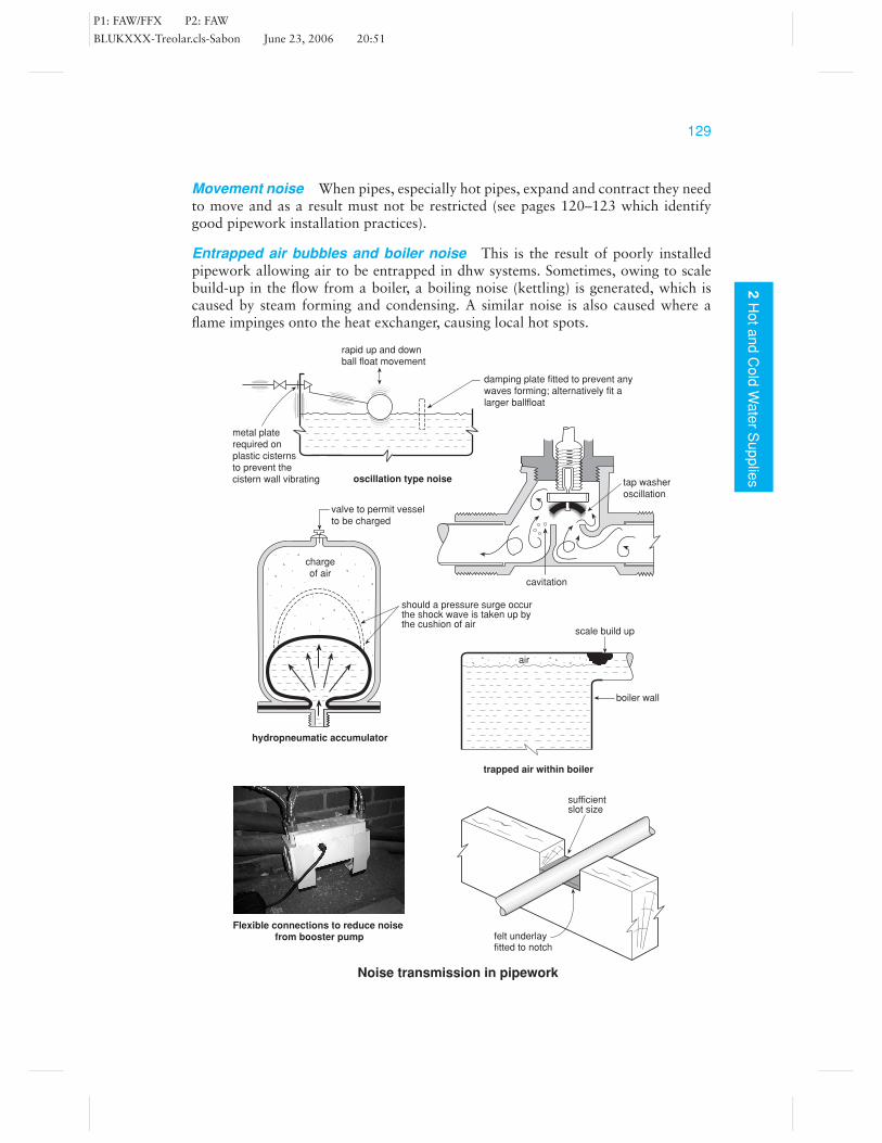
P1: FAW/FFX P2: FAW
BLUKXXX-Treolar.cls-Sabon June 23, 2006 20:51
1292
Ho
ta
nd
Co
ldW
ate
rS
up
plie
s
Movement noise When pipes, especially hot pipes, expand and contract they needto move and as a result must not be restricted (see pages 120–123 which identifygood pipework installation practices).
Entrapped air bubbles and boiler noise This is the result of poorly installedpipework allowing air to be entrapped in dhw systems. Sometimes, owing to scalebuild-up in the flow from a boiler, a boiling noise (kettling) is generated, which iscaused by steam forming and condensing. A similar noise is also caused where aflame impinges onto the heat exchanger, causing local hot spots.
Noise transmission in pipework
sufficientslot size
felt underlayfitted to notch
chargeof air
hydropneumatic accumulator
should a pressure surge occurthe shock wave is taken up bythe cushion of air
valve to permit vesselto be charged
tap washeroscillation
cavitation
boiler wall
scale build up
trapped air within boiler
air
damping plate fitted to prevent anywaves forming; alternatively fit alarger ballfloat
oscillation type noise
metal platerequired onplastic cisternsto prevent thecistern wall vibrating
rapid up and downball float movement
Flexible connections to reduce noise from booster pump
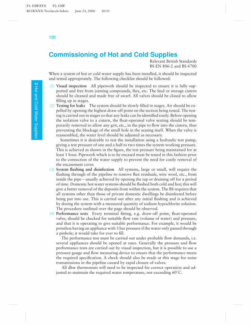
P1: FAW/FFX P2: FAW
BLUKXXX-Treolar.cls-Sabon June 23, 2006 20:51
130
2H
ot
an
dC
old
Wa
ter
Su
pp
lies
Commissioning of Hot and Cold SuppliesRelevant British StandardsBS EN 806-2 and BS 6700
When a system of hot or cold water supply has been installed, it should be inspectedand tested appropriately. The following checklist should be followed:
(1) Visual inspection All pipework should be inspected to ensure it is fully sup-ported and free from jointing compounds, flux, etc. The feed or storage cisternshould be cleaned and made free of swarf. All valves should be closed to allowfilling up in stages.
(2) Testing for leaks The system should be slowly filled in stages. Air should be ex-pelled by opening the highest draw-off point on the section being tested. The test-ing is carried out in stages so that any leaks can be identified easily. Before openingthe isolation valve to a cistern, the float-operated valve seating should be tem-porarily removed to allow any grit, etc., in the pipe to flow into the cistern, thuspreventing the blockage of the small hole in the seating itself. When the valve isreassembled, the water level should be adjusted as necessary.
Sometimes it is desirable to test the installation using a hydraulic test pump,giving a test pressure of one and a half to two times the system working pressure.This is achieved as shown in the figure, the test pressure being maintained for atleast 1 hour. Pipework which is to be encased must be tested in this fashion priorto the connection of the water supply to prevent the need for costly removal ofthe encasement cover.
(3) System flushing and disinfection All systems, large or small, will require theflushing through of the pipeline to remove flux residuals, wire wool, etc., frominside the pipe – usually achieved by opening the tap or draining off for a periodof time. Domestic hot water systems should be flushed both cold and hot; this willgive a better removal of the deposits from within the system. The BS requires thatall systems other than those of private domestic dwellings be disinfected beforebeing put into use. This is carried out after any initial flushing and is achievedby dosing the system with a measured quantity of sodium hypochlorite solution.The procedure outlined over the page should be observed.
(4) Performance tests Every terminal fitting, e.g. draw-off point, float-operatedvalve, should be checked for suitable flow rate (volume of water) and pressure,and that it is operating to give suitable performance. For example, it would bepointless having an appliance with 3 bar pressure if the water only passed througha pinhole; it would take for ever to fill.
The performance test must be carried out under probable flow demands, i.e.several appliances should be opened at once. Generally the pressure and flowperformance tests are carried out by visual inspection, but it is possible to use apressure gauge and flow measuring device to ensure that the performance meetsthe required specification. A check should also be made at this stage for noisetransmissions in the pipeline caused by rapid closure of valves.
All dhw thermostats will need to be inspected for correct operation and ad-justed to maintain the required water temperature, not exceeding 60◦C.

P1: FAW/FFX P2: FAW
BLUKXXX-Treolar.cls-Sabon June 23, 2006 20:51
1312
Ho
ta
nd
Co
ldW
ate
rS
up
plie
s
(5) Final system checks After any problems have been resolved, cistern lids shouldbe secured, insulation material applied, and labels fixed to valves for identificationpurposes, as necessary. The job should be left clean and tidy.
Commissioning of hot and cold supplies
Labels secured tovalves as necessary
Test for water pressure and flow
4.0
3.0
2.0
1.0
0
200
150 105
0
100
50
15bar
pipe blanked off
with fitting to allow
air to be removed
open ends
blanked off pressuregauge
isolatingvalve
drainvalve
operating
handle
flow meter
Hydraulic pressure testing
pressuregauge
200
150 105
0
100
50
15 barlbf/in
2
Pressure and flow test equipment

P1: FAW/FFX P2: FAW
BLUKXXX-Treolar.cls-Sabon June 23, 2006 20:51
132
2H
ot
an
dC
old
Wa
ter
Su
pp
lies
Disinfection of Hot and Cold Water SystemsRelevant British StandardsBS EN 806-2 and BS6700
In relation to industrial and commercial hot and cold water systems used for potablewater supplies it is a requirement that the system is maintained in a condition fit forits purpose. As a result these water systems need to be disinfected in the followingcircumstances:
� Where it is a new installation or has had a major extension� Where it is suspected that contamination may have occurred� Where a system has not been in regular use� Where water is stored in a way that could create the risk of legionnaire’s disease.
Disinfection is carried out by thoroughly flushing and filling the system with ameasured quantity of chlorinated water at 50 ppm. Chlorination is achieved us-ing a sodium hypochlorite solution (similar to household bleach). The solution maybe of various strengths, usually between 5 and 10%, therefore the quantity addedto the system needs to be carefully considered. Where unknown it is best to assumeit to be 10%. Thus if we wish to create a concentration of 50 ppm we would re-quire 50 ÷ 1 000 000 × 100 ÷ 10 = 0.0005 parts of sodium hypochlorite to one partwater, which equates to 1 litre to every 2 000 litres of water in the system.
Assessment of system volume This can be calculated by using the formulaeidentified on page 34. To assist, the following table identifying water volumes incopper tubes may be of use.
Water volume (litres per meter run) for copper tube to BS EN 1057
Tube size Litres/m Tube size Litres/m Tube size Litres/m
15 mm 0.145 35 mm 0.835 66.7 mm 3.247
22 mm 0.320 42 mm 1.232 76 mm 4.197
28 mm 0.539 54 mm 2.091 108 mm 8.659
Safety Prior to undertaking any process of disinfection you must give notice toall parties, including the water authority who may have concern for the water dis-charge. Locate and mark all outlets with an appropriate warning notice advising ofthe operation taking place. In order to avoid toxic fumes being generated no otherchemicals, such as toilet cleaner, should be added to the water discharge until the pro-cess has been completed. COSHH data sheets should be reviewed and appropriatepersonal protective equipment used (i.e. goggles and gloves) when mixing the solu-tion. Where necessary it is possible to remove the chlorine from the water by mixingwith a neutraliser solution, such as sodium thiosulphate, added at a rate of:
System volume (m3) × ppm(mg/L) chlorine × 2 = No. of grams required

P1: FAW/FFX P2: FAW
BLUKXXX-Treolar.cls-Sabon June 23, 2006 20:51
1332
Ho
ta
nd
Co
ldW
ate
rS
up
plie
s
Disinfection procedure for gravity fed systems
1. Undertake the safety procedures described and position warning notices2. Thoroughly flush new systems to remove flux residuals and swarf3. Calculate the capacity of the cistern and add to this water 1 litre of sodium
hypochlorite for every 2000 litres (to check dose is correct see below).4. Working from the cistern, open each draw-off point until the disinfection solution
is detected, usually by smell. Then close this fitting and move to the next outlet,slowly progressing around the system, drawing the solution to all points. As thechlorinated water is drawn off from the cistern it will be necessary to maintain the50 ppm concentration.
5. Once the entire system is full of chlorinated water at the correct dose the systemis left for 1 hour.
6. After the hour has elapsed the chlorine level should be checked in the cistern andat selected outlets. Where this level is less than 30 ppm you need to re-dose andleave for a further hour.
7. Upon successful completion the chlorine can be neutralised before draining.8. Finally the system is thoroughly flushed with clean water until the residual chlorine
level at the outlets is no higher than that present in the supply mains (0.2 ppm).
Disinfection procedure for mains fed systemsWhere no storage cistern is available to introduce the sodium hypochlorite solutionit will be necessary to introduce a temporary branch connection. This allows for apump, checkvalve and cistern, as shown below, to be introduced, thereby allowingthe solution to be added. During dosing the supply would need to be isolated. It maybe possible to add the solution to the highest point in the system, eliminating the needfor a pump.
Checking the chlorine concentrationThis is achieved by using a simple colourimetric test. The procedure involves fillinga small clear plastic tube with a sample of water to be checked. To this is added aspecial tablet. The tube is shaken to dissolve the tablet and the colour of the wateris inspected, which, when compared with the following table, gives an indication ofthe chlorine level.
Water Chlorinecolour level (ppm)
Clear 0Light pink 0.2–1Dark pink 1–5Red 5–10Purple 10–20Blue 20–30Grey/green 30–50Yellow/brown Over 50Colour develops Excessivethen clears
Temporary connection for dosing mains supplies
cistern
type AA air gap
temporary supply
pump checkvalve
system to bedisinfected
supplypipe
temporaryconnection

P1: FAW/FFX P2: FAW
BLUKXXX-Treolar.cls-Sabon June 23, 2006 20:51
134
2H
ot
an
dC
old
Wa
ter
Su
pp
lies
Maintenance and Servicing ScheduleRelevant British StandardsBS EN 806-2 and BS 6700
No system can be guaranteed for ever, but its life expectancy can be greatly improvedby identifying faults before they have a chance to cause inconvenience. Planned pre-ventive maintenance, regularly carried out, will not only help to ensure that the systemperforms as it was intended, but may also prevent costly damage to equipment andbuildings. A maintenance schedule is generally drawn up, and should be observed,giving guidance on what to look for when fulfilling the terms of a servicing contract.
Shown is a typical schedule as used when inspecting a system of hot and cold watersupplies.
Maintenance schedule
Inspection carried out at:Date of Inspection:Inspected by:Remarks:
Component Remarks Inspected Notes
Meters * Read meter and check water consumption forearly signs of wastage
* Confirm in correct working order
Meter and stop valve * Ensure ease of opening to access coverschamber * Clean out as necessary
Earth bonding * Check for alterations and suitable earth bondingmaintained
Water analysis * ‘6 month’ chemical and bacteriological analysisof drinking water systems where bulk storageexceeds 1000 litres
Inspection covers andducting
* Ensure ease of opening to covers and clean outservice ducts as necessary
* Check for signs of leakage from pipework andsurrounding ground or surface water
* Check for the accumulation of gas
In-line control valves * Operate and confirm easy and effectiveoperation
* Labels clearly identify their purpose and aresecurely attached
* Emergency valve keys readily available
Terminal valves * Check for suitable operation and effectiveclosing
* Remove scale build-up and clean sprayheads ofshower mixers, etc.
* Check timing delay of self-closing taps* Adjust water levels to float operated valves* Check for suitable pressure and flow at outlets

P1: FAW/FFX P2: FAW
BLUKXXX-Treolar.cls-Sabon June 23, 2006 20:51
1352
Ho
ta
nd
Co
ldW
ate
rS
up
plie
s
Component Remarks Inspected Notes
Pipework * Check supports and inspect for loose fittings* Check provision is maintained for expansion and
contraction* Check for soundness of pipework* Inspect for signs of corrosion* Inspect insulation material for soundness* Inspect fire stopping to ensure that it is maintained
Storage cisterns * Confirm the cleanliness of vessels* Look for signs of leakage* Check for stagnant water (e.g. dust on surface of
water)* Check condition of cistern supports* Confirm operation of overflow* Ensure lid and insulation are sound
Pumps * Check operation of any pump(s) fitted and ensurenoise levels are mimimal
Pressure andtemperature reliefvalves
* Open test lever to confirm valve not stuck down* Check discharge pipe not blocked
Pressure-reducingvalves
* Check pressures downstream of valve
Pressure vessels * Inspect for corrosion and leakage* Drain vessels of water and measure gas pressure;
adjust if necessary
Filters * Remove gauze/mesh trap and clean out
Electricalcomponents
* Check operation of all controls to includethermostatic devices
* Check suitability of wiring to IEE standards
Any system that has not been fully maintained may fail to meet the requirements ofan insurance policy should a system failure result in damage to the property.
Operative taking water flow, pressure and temperature measurements

P1: FAW/FFX P2: FAW
BLUKXXX-Treolar.cls-Sabon June 23, 2006 20:51
136