Embed Size (px)
Citation preview

Part F
Practical Applications
28. Fan-Cooled Enclosure of a PC System
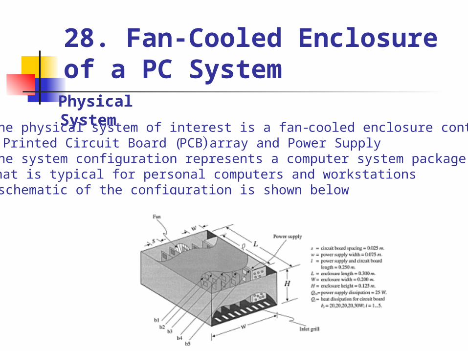
Physical System The physical system of interest is a fan-cooled enclosure containing
a Printed Circuit Board (PCB) array and Power Supply .The system configuration represents a computer system package that is typical for personal computers and workstations .
A schematic of the configuration is shown below
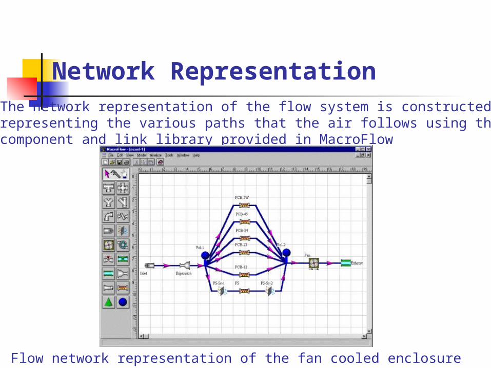
Network Representation The network representation of the flow system is constructed by representing the various paths that the air follows using the component and link library provided in MacroFlow.
Flow network representation of the fan cooled enclosure

Flow Impedance Characteristics
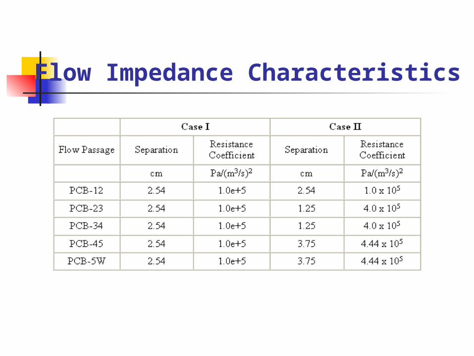
Flow resistance or impedance characteristics of various components need to be specified to complete the network specification .The flow characteristics of the PCB array and the power supply are known from empirical measurements and are expressed in the following form
Analysis has been performed for two cases corresponding to even and uneven spacing of the cards in the array. The loss coefficient B for the Power Supply is constant in both cases and is equal to 3.5 x 10⁵ Pa/ (m3/s)2.The loss coefficient for each passage of the PCB array is listed in Table 28.1.
Each of the cards is assumed to dissipate 50W of heat while the power supply dissipates 167 W.
Flow Impedance Characteristics

Results
Volumetric flow rates for Case I (equally spaced PCB cards)
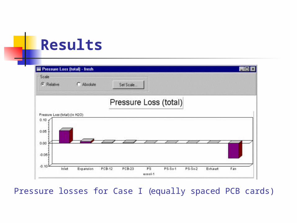
Results
Pressure losses for Case I (equally spaced PCB cards)
Results
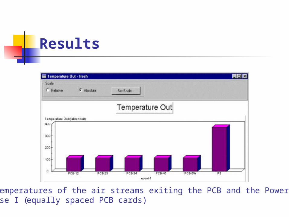
Bulk temperatures of the air streams exiting the PCB and the Power Supply for Case I (equally spaced PCB cards)

Results
Volumetric flow rates for Case II (unequally spaced PCB cards)

Results
Pressure losses for Case II (unequally spaced PCB cards)

Results
Temperatures of the air streams exiting the PCB and the Power Supply for Case II (unequally spaced PCB cards)

29 .Flow over a Heat Sink
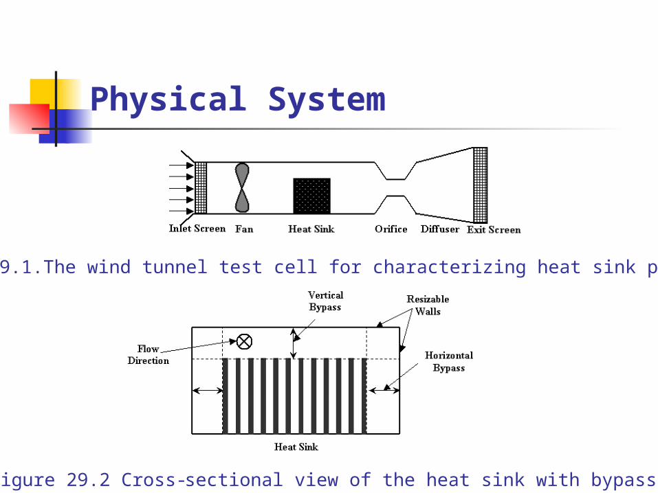
Physical SystemPressure drop and heat transfer characteristics of heat sinks are determined from wind tunnel testing as shown in Figure 29.1
The heat sink is situated inside a duct (wind tunnel). Screens or perforated plates may cover the inlet and the exit of the duct .
The flow within the duct is driven by a fan situated near the inlet and its rate is varied by controlling the opening of the orifice .
Further, the duct size can be varied (by moving the walls or using different sized ducts) to study the effect of bypass on the performance of the heat sink.
Physical System
Figure 29.1.The wind tunnel test cell for characterizing heat sink performance
Figure 29.2 Cross-sectional view of the heat sink with bypass
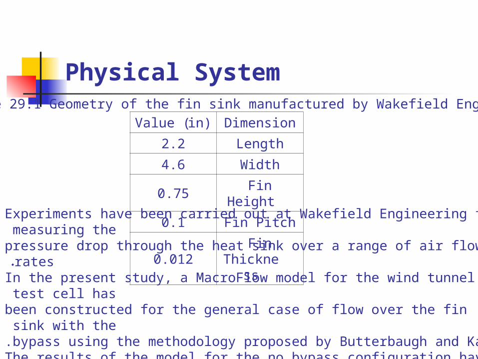
Physical SystemTable 29.1 Geometry of the fin sink manufactured by Wakefield Engineering
DimensionValue (in)
Length2.2
Width4.6
Fin Height0.75
Fin Pitch0.1
Fin Thickness0.012Experiments have been carried out at Wakefield Engineering for measuring the pressure drop through the heat sink over a range of air flow rates. In the present study, a MacroFlow model for the wind tunnel test cell has been constructed for the general case of flow over the fin sink with the bypass using the methodology proposed by Butterbaugh and Kang .The results of the model for the no bypass configuration have been compared with experimental measurements.

Network Representation
MacroFlow representation of the test cell used characterizing the heat sink performance.
Results
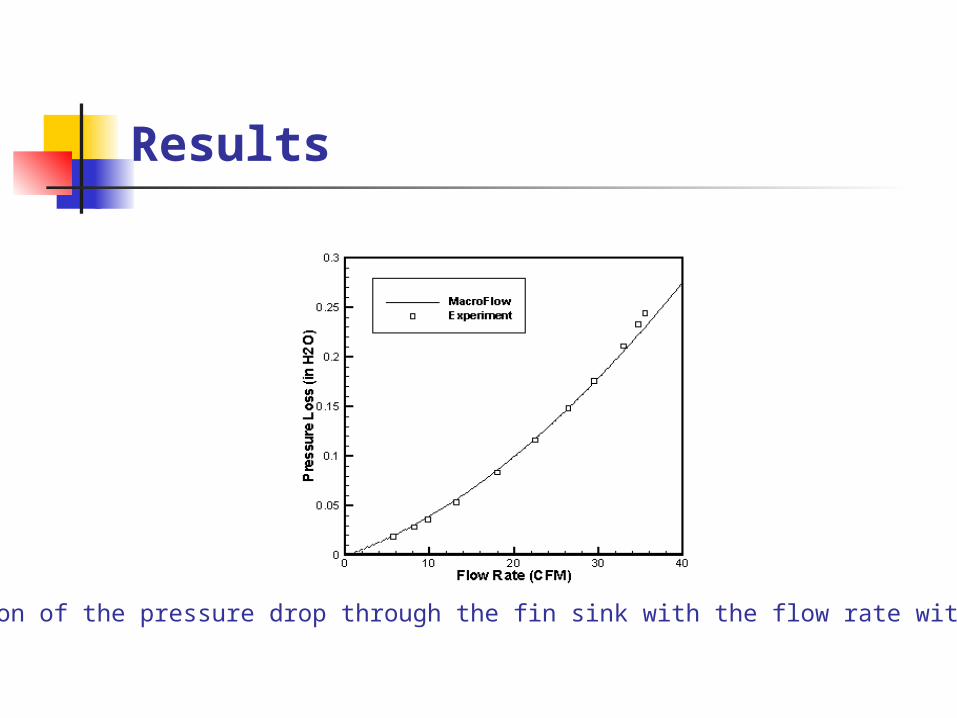
Variation of the pressure drop through the fin sink with the flow rate with no bypass
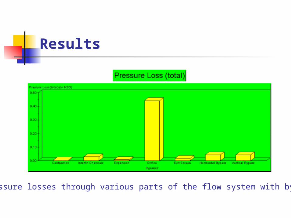
Results
Pressure losses through various parts of the flow system with bypass
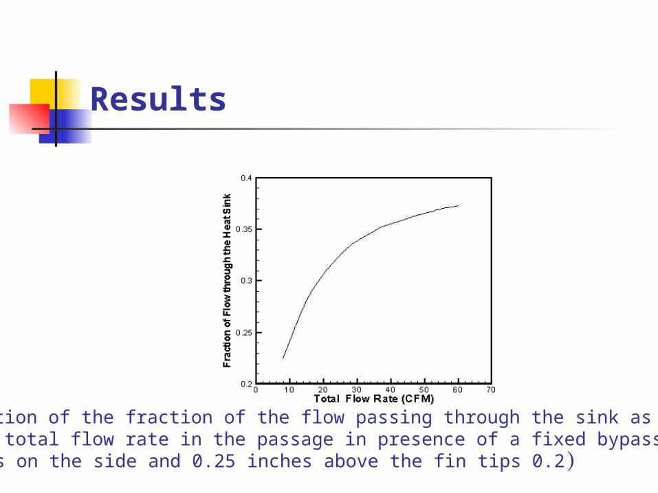
Results
Variation of the fraction of the flow passing through the sink as a function of the total flow rate in the passage in presence of a fixed bypass
(0.2 inches on the side and 0.25 inches above the fin tips )

Thank You


![Midea [MCAC-2011-05] Air cooled Modular Chiller & Fan Coil ... · Title: Midea [MCAC-2011-05] Air cooled Modular Chiller & Fan Coil Unit.pdf Author: CristiM Created Date: 3/15/2012](https://img.pdfslide.us/doc/110x75/5ad5cf287f8b9a177c8d7948/midea-mcac-2011-05-air-cooled-modular-chiller-fan-coil-midea-mcac-2011-05.jpg)