Embed Size (px)
Citation preview
Part C - Suppression of Fire Regulation 10 - Fire-Fighting
1. Purpose The purpose of this regulation is to suppress and swiftly extinguish a fire in the space of origin. For this purpose, the following functional requirements shall be met:
1.1 fixed fire-extinguishing systems shall be installed, having due regard to the fire growth potential of the protected spaces; and
1.2 fire-extinguishing appliances shall be readily available.
2. Water supply systems
Ships shall be provided with fire pumps, fire mains, hydrants and hoses complying with the applicable requirements of this regulation.
2.1 Fire mains and hydrants
2.1.1 General Materials readily rendered ineffective by heat shall not be used for fire mains and hydrants unless adequately protected. The pipes and hydrants shall be so placed that the fire hoses may be easily coupled to them. The arrangement of pipes and hydrants shall be such as to avoid the possibility of freezing. Suitable drainage provisions shall be provided for fire main piping. Isolation valves shall be installed for all open deck fire main branches used for purposes other than fire fighting. In ships where deck cargo may be carried, the positions of the hydrants shall be such that they are always readily accessible and the pipes shall be arranged as far as practicable to avoid risk of damage by such cargo.
2.1.2 Ready availability of water supply The arrangements for the ready availability of water supply shall be:
2.1.2.1 in passenger ships:
2.1.2.1.1 of 1,000 gross tonnage and upwards such that at least one effective jet of water is immediately available from any hydrant in an interior location and so as to ensure the continuation of the output of water by the automatic starting of one required fire pump;
2.1.2.1.2 of less than 1,000 gross tonnage by automatic start of at least one fire pump or
by remote starting from the navigation bridge of at least one fire pump. If the pump starts automatically or if the bottom valve cannot be opened from where the pump is remotely started, the bottom valve shall always be kept open; and
2.1.2.1.3 if fitted with periodically unattended machinery spaces in accordance with regulation II-1/54, the Administration shall determine provisions for fixed water fire-extinguishing arrangement for such spaces equivalent to those required for normally attended machinery spaces;
2.1.2.2 in cargo ships:
2.1.2.2.1 to the satisfaction of the Administration; and
2.1.2.2.2 with a periodically unattended machinery space or when only one person is
required on watch, there shall be immediate water delivery from the fire main system at a suitable pressure, either by remote starting of one of the main fire pumps with remote starting from the navigation bridge and fire control station, if any, or permanent pressurization of the fire main system by one of the main fire pumps, except that the Administration may waive this requirement for cargo ships of less than 1,600 gross tonnage if the fire pump starting arrangement in the machinery space is in an easily accessible position.
2.1.3 Diameter of fire mains
The diameter of the fire main and water service pipes shall be sufficient for the effective distribution of the maximum required discharge from two fire pumps operating simultaneously, except that in the case of cargo ships the diameter need only be sufficient for the discharge of 140 m³/h.
2.1.4 Isolating valves and relief valves
2.1.4.1 Isolating valves to separate the section of the fire main within the machinery space containing the main fire pump or pumps from the rest of the fire main shall be fitted in an easily accessible and tenable position outside the machinery spaces. The fire main shall be so arranged that when the isolating valves are shut all the hydrants on the ship, except those in the machinery space referred to above, can be supplied with water by another fire pump or an emergency fire pump. The emergency fire pump, its seawater inlet, and suction and delivery pipes and isolating valves shall be located outside the machinery space. If this arrangement cannot be made, the sea-chest may be fitted in the machinery space if the valve is remotely controlled from a position in the same compartment as the emergency fire pump and the suction pipe is as short as practicable. Short lengths of suction or discharge piping may penetrate the machinery space, provided they are enclosed in a substantial steel casing or are insulated to "A-60" class standards. The pipes shall have substantial wall thickness, but in no case less than 11 mm, and shall be welded except for the flanged connection to the sea inlet valve.
2.1.4.2 A valve shall be fitted to serve each fire hydrant so that any fire hose may be
removed while the fire pumps are in operation.
2.1.4.3 Relief valves shall be provided in conjunction with fire pumps if the pumps are capable of developing a pressure exceeding the design pressure of the water service pipes, hydrants and hoses. These valves shall be so placed and adjusted as to prevent excessive pressure in any part of the fire main system.
2.1.4.4 In tankers, isolation valves shall be fitted in the fire main at the poop front in a
protected position and on the tank deck at intervals of not more than 40 m to preserve the integrity of the fire main system in case of fire or explosion.
2.1.5 Number and position of hydrants
2.1.5.1 The number and position of hydrants shall be such that at least two jets of water
not emanating from the same hydrant, one of which shall be from a single length of hose, may reach any part of the ship normally accessible to the passengers or crew while the ship is being navigated and any part of any cargo space when
empty, any ro-ro space or any vehicle space in which latter case the two jets shall reach any part of the space, each from a single length of hose. Furthermore, such hydrants shall be positioned near the accesses to the protected spaces.
2.1.5.2 In addition to the requirements in paragraph 2.1.5.1, passenger ships shall comply
with the following:
2.1.5.2.1 in the accommodation, service and machinery spaces, the number and position of hydrants shall be such that the requirements of paragraph 2.1.5.1 may be complied with when all watertight doors and all doors in main vertical zone bulkheads are closed; and
2.1.5.2.2 where access is provided to a machinery space of category A at a low level
from an adjacent shaft tunnel, two hydrants shall be provided external to, but near the entrance to, that machinery space. Where such access is provided from other spaces, in one of those spaces two hydrants shall be provided near the entrance to the machinery space of category A. Such provision need not be made where the tunnel or adjacent spaces are not part of the escape route.
2.1.6 Pressure at hydrants
With the two pumps simultaneously delivering water through the nozzles specified in paragraph 2.3.3, with the quantity of water as specified in paragraph 2.1.3, through any adjacent hydrants, the following minimum pressures shall be maintained at all hydrants:
2.1.6.1 for passenger ships: 4,000 gross tonnage and upwards 0.40 N/mm² less than 4,000 gross tonnage 0.30 N/mm²
2.1.6.2 for cargo ships:
6,000 gross tonnage and upwards 0.27 N/mm² less than 6,000 gross tonnage 0.25 N/mm²
and
2.1.6.3 the maximum pressure at any hydrant shall not exceed that at which the effective control of a fire hose can be demonstrated.
2.1.7 International shore connection
2.1.7.1 Ships of 500 gross tonnage and upwards shall be provided with at least one
international shore connection complying with the Fire Safety Systems Code.
2.1.7.2 Facilities shall be available enabling such a connection to be used on either side of the ship.
2.2 Fire pumps
2.2.1 Pumps accepted as fire pumps
Sanitary, ballast, bilge or general service pumps may be accepted as fire pumps, provided that they are not normally used for pumping oil and that if they are subject to occasional duty for the transfer or pumping of oil fuel, suitable change-over arrangements are fitted.
2.2.2 Number of fire pumps Ships shall be provided with independently driven fire pumps as follows:
2.2.2.1 in passenger ships of: 4,000 gross tonnage and upwards at least three less than 4,000 gross tonnage at least two
2.2.2.2 in cargo ships of:
1,000 gross tonnage and upwards at least two less than 1,000 gross tonnage at least two power-driven pumps, one of which shall be independently driven.
2.2.3 Arrangement of fire pumps and fire mains
2.2.3.1 Fire pumps
The arrangement of sea connections, fire pumps and their sources of power shall be as to ensure that:
2.2.3.1.1 in passenger ships of 1,000 gross tonnage and upwards, in the event of a fire in any one compartment, all the fire pumps will not be put out of action; and
2.2.3.1.2 in passenger ships of less than 1,000 gross tonnage and in cargo ships, if a
fire in any one compartment could put all the pumps out of action, there shall be an alternative means consisting of an emergency fire pump complying with the provisions of the Fire Safety Systems Code with its source of power and sea connection located outside the space where the main fire pumps or their sources of power are located.
2.2.3.2 Requirements for the space containing the emergency fire pump
2.2.3.2.1 Location of the space
The space containing the fire pump shall not be contiguous to the boundaries of machinery spaces of category A or those spaces containing main fire pumps. Where this is not practicable, the common bulkhead between the two spaces shall be insulated to a standard of structural fire protection equivalent to that required for a control station.
2.2.3.2.2 Access to the emergency fire pump No direct access shall be permitted between the machinery space and the space containing the emergency fire pump and its source of power. When this is impracticable, the Administration may accept an arrangement where the access is by means of an airlock with the door of the machinery space being of "A-60" class standard and the other door being at least steel, both reasonably gastight, self-closing and without any hold-back arrangements. Alternatively, the access may be through a watertight door capable of being operated from a space remote from the machinery space and the space containing the emergency fire pump and unlikely to be cut off in the event of fire in those spaces. In such cases, a second means of access to the space containing the emergency fire pump and its source of power shall be provided.
2.2.3.2.3 Ventilation of the emergency fire pump space
Ventilation arrangements to the space containing the independent source of power for the emergency fire pump shall be such as to preclude, as far as practicable, the possibility of smoke from a machinery space fire entering or being drawn into that space.
2.2.3.3 Additional pumps for cargo ships In addition, in cargo ships where other pumps, such as general service, bilge and ballast, etc., are fitted in a machinery space, arrangements shall be made to ensure that at least one of these pumps, having the capacity and pressure required by paragraphs 2.1.6.2 and 2.2.4.2, is capable of providing water to the fire main.
2.2.4 Capacity of fire pumps
2.2.4.1 Total capacity of required fire pumps The required fire pumps shall be capable of delivering for fire-fighting purposes a quantity of water, at the pressure specified in paragraph 2.1.6, as follows:
2.2.4.1.1 pumps in passenger ships: the quantity of water is not less than two thirds of the quantity required to be dealt with by the bilge pumps when employed for bilge pumping; and
2.2.4.1.2 pumps in cargo ships, other than any emergency pump: the quantity of water
is not less than four thirds of the quantity required under regulation II-1/21 to be dealt with by each of the independent bilge pumps in a passenger ship of the same dimension when employed in bilge pumping, provided that in no cargo ship need the total required capacity of the fire pumps exceed 180 m³/h.
2.2.4.2 Capacity of each fire pump
Each of the required fire pumps (other than any emergency pump required in paragraph 2.2.3.1.2 for cargo ships) shall have a capacity not less than 80% of the total required capacity divided by the minimum number of required fire pumps but in any case not less than 25 m³/h, and each such pump shall in any event be capable of delivering at least the two required jets of water. These fire pumps shall be capable of supplying the fire main system under the required conditions. Where more pumps than the minimum of required pumps are installed, such additional pumps shall have a capacity of at least 25 m³/h and shall be capable of delivering at least the two jets of water required in paragraph 2.1.5.1.
2.3 Fire hoses and nozzles
2.3.1 General specifications
2.3.1.1 Fire hoses shall be of non-perishable material approved by the Administration and shall be sufficient in length to project a jet of water to any of the spaces in which they may be required to be used. Each hose shall be provided with a nozzle and the necessary couplings. Hoses specified in this chapter as "fire hoses" shall, together with any necessary fittings and tools, be kept ready for use in conspicuous positions near the water service hydrants or connections. Additionally, in interior locations in passenger ships carrying more than 36 passengers, fire hoses shall be connected to the hydrants at all times. Fire hoses shall have a length of at least 10 m, but not more than:
2.3.1.1.1 15 m in machinery spaces;
2.3.1.1.2 20 m in other spaces and open decks; and
2.3.1.1.3 25 m for open decks on ships with a maximum breadth in excess of 30 m.
2.3.1.2 Unless one hose and nozzle is provided for each hydrant in the ship, there shall be complete interchangeability of hose couplings and nozzles.
2.3.2 Number and diameter of fire hoses
2.3.2.1 Ships shall be provided with fire hoses, the number and diameter of which shall be
to the satisfaction of the Administration.
2.3.2.2 In passenger ships, there shall be at least one fire hose for each of the hydrants required by paragraph 2.1.5 and these hoses shall be used only for the purposes of extinguishing fires or testing the fire-extinguishing apparatus at fire drills and surveys.
2.3.2.3 In cargo ships:
2.3.2.3.1 of 1,000 gross tonnage and upwards, the number of fire hoses to be provided
shall be one for each 30 m length of the ship and one spare, but in no case less than five in all. This number does not include any hoses required in any engine-room or boiler room. The Administration may increase the number of hoses required so as to ensure that hoses in sufficient number are available and accessible at all times, having regard to the type of ship and the nature of trade in which the ship is employed. Ships carrying dangerous goods in accordance with regulation 19 shall be provided with three hoses and nozzles, in addition to those required above; and
2.3.2.3.2 of less than 1,000 gross tonnage, the number of fire hoses to be provided shall
be calculated in accordance with the provisions of paragraph 2.3.2.3.1. However, the number of hoses shall in no case be less than three.
2.3.3 Size and types of nozzles
2.3.3.1 For the purposes of this chapter, standard nozzle sizes shall be 12 mm, 16 mm
and 19 mm or as near thereto as possible. Larger diameter nozzles may be permitted at the discretion of the Administration.
2.3.3.2 For accommodation and service spaces, a nozzle size greater than 12 mm need
not be used.
2.3.3.3 For machinery spaces and exterior locations, the nozzle size shall be such as to obtain the maximum discharge possible from two jets at the pressure mentioned in paragraph 2.1.6 from the smallest pump, provided that a nozzle size greater than 19 mm need not be used.
2.3.3.4 Nozzles shall be of an approved dual-purpose type (i.e. spray/jet type)
incorporating a shutoff.
3. Portable fire extinguishers
3.1 Type and design
Portable fire extinguishers shall comply with the requirements of the Fire Safety Systems Code.
3.2 Arrangement of fire extinguishers
3.2.1 Accommodation spaces, service spaces and control stations shall be provided with portable fire extinguishers of appropriate types and in sufficient number to the satisfaction of the Administration. Ships of 1,000 gross tonnage and upwards shall carry at least five portable fire extinguishers.
3.2.2 One of the portable fire extinguishers intended for use in any space shall be stowed
near the entrance to that space.
3.2.3 Carbon dioxide fire extinguishers shall not be placed in accommodation spaces. In control stations and other spaces containing electrical or electronic equipment or appliances necessary for the safety of the ship, fire extinguishers should be provided whose extinguishing media are neither electrically conductive nor harmful to the equipment and appliances.
3.2.4 Fire extinguishers shall be situated ready for use at easily visible places, which can
be reached quickly and easily at any time in the event of a fire, and in such a way that their serviceability is not impaired by the weather, vibration or other external factors. Portable fire extinguishers shall be provided with devices which indicate whether they have been used.
3.3 Spare charges
3.3.1 Spare charges shall be provided for 100% of the first ten extinguishers and 50% of
the remaining fire extinguishers capable of being recharged on board. Not more than sixty total spare charges are required. Instructions for recharging shall be carried on board.
3.3.2 For fire extinguishers which cannot be recharged on board, additional portable fire
extinguishers of the same quantity, type, capacity and number as determined in paragraph 3.3.1 above shall be provided in lieu of spare charges.
4. Fixed fire-extinguishing systems
4.1 Types of fixed fire-extinguishing systems
4.1.1 A fixed fire-extinguishing system required by paragraph 5 below may be any of the
following systems:
4.1.1.1 a fixed gas fire-extinguishing system complying with the provisions of the Fire Safety Systems Code;
4.1.1.2 a fixed high-expansion foam fire-extinguishing system complying with the
provisions of the Fire Safety Systems Code; and
4.1.1.3 a fixed pressure water-spraying fire-extinguishing system complying with the provisions of the Fire Safety Systems Code.
4.1.2 Where a fixed fire-extinguishing system not required by this chapter is installed, it
shall meet the requirements of the relevant regulations of this chapter and the Fire Safety Systems Code.
4.1.3 Fire-extinguishing systems using Halon 1211, 1301, and 2402 and
perfluorocarbons shall be prohibited.
4.1.4 In general, the Administration shall not permit the use of steam as a fire-extinguishing medium in fixed fire-extinguishing systems. Where the use of steam is permitted by the Administration, it shall be used only in restricted areas as an addition to the required fire-extinguishing system and shall comply with the requirements of the Fire Safety System Code.
4.2 Closing appliances for fixed gas fire-extinguishing systems
Where a fixed gas fire-extinguishing system is used, openings which may admit air to, or allow gas to escape from, a protected space shall be capable of being closed from outside the protected space.
4.3 Storage rooms of fire-extinguishing medium When the fire-extinguishing medium is stored outside a protected space, it shall be stored in a room which is located behind the forward collision bulkhead, and is used for no other purposes. Any entrance to such a storage room shall preferably be from the open deck and shall be independent of the protected space. If the storage space is located below deck, it shall be located no more than one deck below the open deck and shall be directly accessible by a stairway or ladder from the open deck. Spaces which are located below deck or spaces where access from the open deck is not provided shall be fitted with a mechanical ventilation system designed to take exhaust air from the bottom of the space and shall be sized to provide at least 6 air changes per hour. Access doors shall open outwards, and bulkheads and decks, including doors and other means of closing any opening therein, which form the boundaries between such rooms and adjacent enclosed spaces shall be gastight. For the purpose of the application of tables 9.1 to 9.8, such storage rooms shall be treated as fire control stations.
4.4 Water pumps for other fire-extinguishing systems Pumps, other than those serving the fire main, required for the provision of water for fire-extinguishing systems required by this chapter, their sources of power and their controls shall be installed outside the space or spaces protected by such systems and shall be so arranged that a fire in the space or spaces protected will not put any such system out of action.
5. Fire-extinguishing arrangements in machinery spaces
5.1 Machinery spaces containing oil-fired boilers or oil fuel units
5.1.1 Fixed fire-extinguishing systems Machinery spaces of category A containing oil-fired boilers or oil fuel units shall be provided with any one of the fixed fire-extinguishing systems in paragraph 4.1. In each case, if the engine-room and boiler room are not entirely separate, or if fuel oil can drain from the boiler room into the engine-room, the combined engine and boiler rooms shall be considered as one compartment.
5.1.2 Additional fire-extinguishing arrangements
5.1.2.1 There shall be in each boiler room or at an entrance outside of the boiler room at least one portable foam applicator unit complying with the provisions of the Fire Safety Systems Code.
5.1.2.2 There shall be at least two portable foam extinguishers or equivalent in each firing
space in each boiler room and in each space in which a part of the oil fuel installation is situated. There shall be not less than one approved foam type extinguisher of at least 135 l capacity or equivalent in each boiler room. These extinguishers shall be provided with hoses on reels suitable for reaching any part of the boiler room. In the case of domestic boilers of less than 175 kW an approved foam type extinguisher of at least 135 l capacity is not required.
5.1.2.3 In each firing space there shall be a receptacle containing at least 0.1 m³ sand,
sawdust impregnated with soda, or other approved dry material, along with a suitable shovel for spreading the material. An approved portable extinguisher may be substituted as an alternative.
5.2 Machinery spaces containing internal combustion machinery
5.2.1 Fixed fire-extinguishing systems
Machinery spaces of category A containing internal combustion machinery shall be provided with one of the fixed fire-extinguishing systems in paragraph 4.1.
5.2.2 Additional fire-extinguishing arrangements
5.2.2.1 There shall be at least one portable foam applicator unit complying with the provisions of the Fire Safety Systems Code.
5.2.2.2 There shall be in each such space approved foam-type fire extinguishers, each of
at least 45 l capacity or equivalent, sufficient in number to enable foam or its equivalent to be directed on to any part of the fuel and lubricating oil pressure systems, gearing and other fire hazards. In addition, there shall be provided a sufficient number of portable foam extinguishers or equivalent which shall be so located that no point in the space is more than 10 m walking distance from an extinguisher and that there are at least two such extinguishers in each such space. For smaller spaces of cargo ships the Administration may consider relaxing this requirement.
5.3 Machinery spaces containing steam turbines or enclosed steam engines
5.3.1 Fixed fire-extinguishing systems
In spaces containing steam turbines or enclosed steam engines used for main propulsion or other purposes having in the aggregate a total output of not less than 375 kW, one of the fire-extinguishing systems specified in paragraph 4.1 shall be provided if such spaces are periodically unattended.
5.3.2 Additional fire-extinguishing arrangements
5.3.2.1 There shall be approved foam fire extinguishers, each of at least 45 l capacity or equivalent, sufficient in number to enable foam or its equivalent to be directed on to any part of the pressure lubrication system, on to any part of the casings enclosing pressure-lubricated parts of the turbines, engines or associated gearing, and any other fire hazards. However, such extinguishers shall not be required if protection, at least equivalent to that required by this subparagraph, is provided in such spaces by a fixed fire-extinguishing system fitted in compliance with paragraph 4.1.
5.3.2.2 There shall be a sufficient number of portable foam extinguishers or equivalent
which shall be so located that no point in the space is more than 10 m walking distance from an extinguisher and that there are at least two such extinguishers in each such space, except that such extinguishers shall not be required in addition to any provided in compliance with paragraph 5.1.2.2.
5.4 Other machinery spaces
Where, in the opinion of the Administration, a fire hazard exists in any machinery space for which no specific provisions for fire-extinguishing appliances are prescribed in paragraphs 5.1, 5.2 and 5.3, there shall be provided in, or adjacent to, that space such a number of approved portable fire extinguishers or other means of fire extinction as the Administration may deem sufficient.
5.5 Additional requirements for passenger ships In passenger ships carrying more than 36 passengers, each machinery space of category A shall be provided with at least two suitable water fog applicators.* * A water fog applicator might consist of a metal L-shaped pipe, the long limb being about 2 m in length, capable of being fitted to a fire hose, and the short limb being about 250 mm in length, fitted with a fixed water fog nozzle or capable of being fitted with a water spray nozzle.
5.6 Fixed local application fire-fighting systems
5.6.1 Paragraph 5.6 shall apply to passenger ships of 500 gross tonnage and above and cargo ships of 2,000 gross tonnage and above.
5.6.2 Machinery spaces of category A above 500 m³ in volume shall, in addition to the
fixed fire-extinguishing system required in paragraph 5.1.1, be protected by an approved type of fixed water based or equivalent local application fire-fighting system, based on the guidelines developed by the Organization.‡ In the case of periodically unattended machinery spaces, the fire-extinguishing system shall have both automatic and manual release capabilities. In the case of continuously manned machinery spaces, the fire-extinguishing system is only required to have a manual release capability.
‡ Refer to the Guidelines for the approval of fixed water-based local application fire-fighting systems for use in category A machinery spaces (MSC/Circ.913).
5.6.3 Fixed local application fire-extinguishing systems are to protect areas such as the following without the necessity of engine shutdown, personnel evacuation, or sealing of the spaces:
5.6.3.1 the fire hazard portions of internal combustion machinery used for the ship's main
propulsion and power generation;
5.6.3.2 boiler fronts;
5.6.3.3 the fire hazard portions of incinerators; and
5.6.3.4 purifiers for heated fuel oil.
5.6.4 Activation of any local application system shall give a visual and distinct audible alarm in the protected space and at continuously manned stations. The alarm shall indicate the specific system activated. The system alarm requirements described within this paragraph are in addition to, and not a substitute for, the detection and fire alarm system required elsewhere in this chapter.
6. Fire-extinguishing arrangements in control stations, accommodation and
service spaces
6.1 Sprinkler systems in passenger ships
6.1.1 Passenger ships carrying more than 36 passengers shall be equipped with an automatic sprinkler, fire detection and fire alarm system of an approved type complying with the requirements of the Fire Safety Systems Code in all control stations, accommodation and service spaces, including corridors and stairways. Alternatively, control stations, where water may cause damage to essential equipment, may be fitted with an approved fixed fire-extinguishing system of another type. Spaces having little or no fire risk such as voids, public toilets, carbon dioxide rooms and similar spaces need not be fitted with an automatic sprinkler system.
6.1.2 In passenger ships carrying not more than 36 passengers, when a fixed smoke
detection and fire alarm system complying with the provisions of the Fire Safety Systems Code is provided only in corridors, stairways and escape routes within accommodation spaces, an automatic sprinkler system shall be installed in accordance with regulation 7.5.3.2.
6.2 Sprinkler systems for cargo ships
In cargo ships in which method IIC specified in regulation 9.2.3.1.1.2 is adopted, an automatic sprinkler, fire detection and fire alarm system shall be fitted in accordance with the requirements in regulation 7.5.5.2.
6.3 Spaces containing flammable liquid
6.3.1 Paint lockers shall be protected by:
6.3.1.1 a carbon dioxide system, designed to give a minimum volume of free gas equal to 40% of the gross volume of the protected space;
6.3.1.2 a dry powder system, designed for at least 0.5 kg powder/m³
6.3.1.3 a water spraying or sprinkler system, designed for 5 l/m² min. Water spraying
systems may be connected to the fire main of the ship; or
6.3.1.4 a system providing equivalent protection, as determined by the Administration. In all cases, the system shall be operable from outside the protected space.
6.3.2 Flammable liquid lockers shall be protected by an appropriate fire-extinguishing arrangement approved by the Administration.
6.3.3 For lockers of a deck area of less than 4 m², which do not give access to
accommodation spaces, a portable carbon dioxide fire extinguisher sized to provide a minimum volume of free gas equal to 40% of the gross volume of the
space may be accepted in lieu of a fixed system. A discharge port shall be arranged in the locker to allow the discharge of the extinguisher without having to enter into the protected space. The required portable fire extinguisher shall be stowed adjacent to the port. Alternatively, a port or hose connection may be provided to facilitate the use of fire main water.
6.4 Deep-fat cooking equipment
Deep-fat cooking equipment shall be fitted with the following:
6.4.1 an automatic or manual fire-extinguishing system tested to an international standard acceptable to the Organization;*
* Refer to the recommendations by the International Organization for Standardization, in particular publication ISO 15371:2000, Fire-extinguishing systems for protection of galley deep fat cooking equipment.
6.4.2 a primary and backup thermostat with an alarm to alert the operator in the event of failure of either thermostat;
6.4.3 arrangements for automatically shutting off the electrical power upon activation of
the fire-extinguishing system;
6.4.4 an alarm for indicating operation of the fire-extinguishing system in the galley where the equipment is installed; and
6.4.5 controls for manual operation of the fire-extinguishing system which are clearly
labelled for ready use by the crew.
7. Fire-extinguishing arrangements in cargo spaces
7.1 Fixed gas fire-extinguishing systems for general cargo
7.1.1 Except as provided for in paragraph 7.2, the cargo spaces of passenger ships of 1,000 gross tonnage and upwards shall be protected by a fixed carbon dioxide or inert gas fire-extinguishing system complying with the provisions of the Fire Safety Systems Code or by a fixed high-expansion foam fire-extinguishing system which gives equivalent protection.
7.1.2 Where it is shown to the satisfaction of the Administration that a passenger ship is
engaged on voyages of such short duration that it would be unreasonable to apply the requirements of paragraph 7.1.1 and also in ships of less than 1,000 gross tonnage, the arrangements in cargo spaces shall be to the satisfaction of the Administration, provided that the ship is fitted with steel hatch covers and effective means of closing all ventilators and other openings leading to the cargo spaces.
7.1.3 Except for ro-ro and vehicle spaces, cargo spaces on cargo ships of 2,000 gross
tonnage and upwards shall be protected by a fixed carbon dioxide or inert gas fire-extinguishing system complying with the provisions of the Fire Safety Systems Code, or by a fire-extinguishing system which gives equivalent protection.
7.1.4 The Administration may exempt from the requirements of paragraphs 7.1.3 and
7.2, cargo spaces of any cargo ship if constructed, and solely intended for, the carriage of ore, coal, grain, unseasoned timber, non-combustible cargoes or cargoes which, in the opinion of the Administration, constitute a low fire risk.* Such
exemptions may be granted only if the ship is fitted with steel hatch covers and effective means of closing all ventilators and other openings leading to the cargo spaces. When such exemptions are granted, the Administration shall issue an Exemption Certificate, irrespective of the date of construction of the ship concerned, in accordance with regulation I/12(a)(vi), and shall ensure that the list of cargoes the ship is permitted to carry is attached to the Exemption Certificate.
* Refer to the Code of Safe Practice for Solid Bulk Cargoes, emergency schedule B14, entry for coal, and to the List of solid bulk cargoes which are non-combustible or constitute a low fire risk or for which a fixed gas fire-extinguishing system is ineffective (MSC/Circ.671).
7.2 Fixed gas fire-extinguishing systems for dangerous goods A ship engaged in the carriage of dangerous goods in any cargo spaces shall be provided with a fixed carbon dioxide or inert gas fire-extinguishing system complying with the provisions of the Fire Safety Systems Code or with a fire-extinguishing system which, in the opinion of the Administration, gives equivalent protection for the cargoes carried.
8. Cargo tank protection
8.1 Fixed deck foam fire-extinguishing systems
8.1.1 For tankers of 20,000 tonnes deadweight and upwards, a fixed deck foam fire-extinguishing system shall be provided complying with the provisions of the Fire Safety Systems Code, except that, in lieu of the above, the Administration, after having given consideration to the ship's arrangement and equipment, may accept other fixed installations if they afford protection equivalent to the above, in accordance with regulation I/5. The requirements for alternative fixed installations shall comply with the requirements in paragraph 8.1.2.
8.1.2 In accordance with paragraph 8.1.1, where the Administration accepts an
equivalent fixed installation in lieu of the fixed deck foam fire-extinguishing system, the installation shall:
8.1.2.1 be capable of extinguishing spill fires and also preclude ignition of spilled oil not
yet ignited; and
8.1.2.2 be capable of combating fires in ruptured tanks.
8.1.3 Tankers of less than 20,000 tonnes deadweight shall be provided with a deck foam fire-extinguishing system complying with the requirements of the Fire Safety Systems Code.
9. Protection of cargo pump-rooms in tankers
9.1 Fixed fire-extinguishing systems
Each cargo pump-room shall be provided with one of the following fixed fire-extinguishing systems operated from a readily accessible position outside the pump-room. Cargo pump-rooms shall be provided with a system suitable for machinery spaces of category A.
9.1.1 A carbon dioxide fire-extinguishing system complying with the provisions the Fire Safety Systems Code and with the following:
9.1.1.1 the alarms giving audible warning of the release of fire-extinguishing medium shall be safe for use in a flammable cargo vapour/air mixture; and
9.1.1.2 a notice shall be exhibited at the controls stating that, due to the electrostatic
ignition hazard, the system is to be used only for fire extinguishing and not for inerting purposes.
9.1.2 A high-expansion foam fire-extinguishing system complying with the provisions of
the Fire Safety Systems Code, provided that the foam concentrate supply is suitable for extinguishing fires involving the cargoes carried.
9.1.3 A fixed pressure water-spraying fire-extinguishing system complying with the
provisions of the Fire Safety Systems Code.
9.2 Quantity of fire-extinguishing medium Where the fire-extinguishing medium used in the cargo pump-room system is also used in systems serving other spaces, the quantity of medium provided or its delivery rate need not be more than the maximum required for the largest compartment.
10. Fire-fighter's outfits
10.1 Types of fire-fighter's outfits Fire-fighter's outfits shall comply with the Fire Safety Systems Code.
10.2 Number of fire-fighter's outfits
10.2.1 Ships shall carry at least two fire-fighter's outfits.
10.2.2 In addition, in passenger ships there shall be provided:
10.2.2.1 for every 80 m, or part thereof, of the aggregate of the lengths of all passenger spaces and service spaces on the deck which carries such spaces or, if there is more than one such deck, on the deck which has the largest aggregate of such lengths, two fire-fighter's outfits and, in addition, two sets of personal equipment, each set comprising the items stipulated in the Fire Safety Systems Code. In passenger ships carrying more than 36 passengers, two additional fire-fighter's outfits shall be provided for each main vertical zone. However, for stairway enclosures which constitute individual main vertical zones and for the main vertical zones in the fore or aft end of a ship which do not contain spaces of categories (6), (7), (8) or (12) defined in regulation 9.2.2.3, no additional fire-fighter's outfits are required; and
10.2.2.2 on ships carrying more than 36 passengers, for each pair of breathing
apparatus, one water fog applicator which shall be stored adjacent to such apparatus.
10.2.3 In addition, in tankers, two fire-fighter's outfits shall be provided.
10.2.4 The Administration may require additional sets of personal equipment and
breathing apparatus, having due regard to the size and type of the ship.
10.2.5 Two spare charges shall be provided for each required breathing apparatus. Passenger ships carrying not more than 36 passengers and cargo ships that are

equipped with suitably located means for fully recharging the air cylinders free from contamination need carry only one spare charge for each required apparatus. In passenger ships carrying more than 36 passengers, at least two spare charges for each breathing apparatus shall be provided.
10.3 Storage of fire-fighter's outfits
10.3.1 The fire-fighter's outfits or sets of personal equipment shall be kept ready for use
in an easily accessible location that is permanently and clearly marked and, where more than one fire-fighter's outfit or more than one set of personal equipment is carried, they shall be stored in widely separated positions.
10.3.2 In passenger ships, at least two fire-fighter's outfits and, in addition, one set of
personal equipment shall be available at any one position. At least two fire-fighter's outfits shall be stored in each main vertical zone.
MCA Guidance G1 Independently driven power operated emergency fire pumps G1.1 When the emergency pump is the only means of providing water for the operation of, or use in connection with, a required fixed fire extinguishing installation for the machinery space, regard should be paid particularly to the ready accessibility of the pump controls in all weather conditions so that the system can be brought quickly into use. G1.2 In tankers, there should, in general, be a cofferdam or void space between the space containing the emergency fire pump and any adjacent cargo oil tank, unless the pump is driven from a prime mover situated in a non-hazardous area outside the space. The means for driving the pump, e.g. pneumatic or hydraulic transmission, should be safe and suitable for use within the space containing the emergency fire pump, the pump suction and discharge valves should be capable of being operated from outside the space and the prime mover should be in a non-hazardous area. Notwithstanding the above, it is considered undesirable for the emergency fire pump so driven to be placed in a hazardous area of a tanker having common boundaries with the machinery space containing the main fire pumps or their source of power. Where it is impracticable for the pump to be sited elsewhere, however, proposals to locate it within the main cargo pump room would be considered on their merits. G1.3 Where the emergency fire pump is used for the production of foam for a machinery space fixed foam system, or for recharging a pre-mixed foam installation, the pump capacity should be sufficient for this purpose in addition to the jets of water required by the Regulations. G1.4 Starting arrangements for emergency fire pumps must be outside and independent of the space containing the main fire pumps. If manual starting is impracticable the other means of starting should include those by compressed air, electricity or other sources of stored energy, hydraulic power or starting cartridges. G1.5 For the purposes of the Regulations and this guidance the fire main should be deemed to start at the fire pump discharge valve and hence includes all parts of the fire main and branches both within and outside the machinery space. G1.6 For the purposes of the Regulations the fire main should be deemed to start at the fire pump discharge valve and hence includes all parts of the fire main and branches both within and outside the machinery space.
G1.7 In every ship of Class I, II, or II(A) any emergency fire pump shall be situated in a position aft of the ship's collision bulkhead. G2 Hydrants G2.1 Where the Regulations require a fire hydrant to be fitted in the tunnel the arrangements should ensure that the hydrant can be supplied by the emergency fire pump when the machinery space fire main is isolated. When not required by Regulations, because of the advantages in attacking a machinery space fire from a low level, the provision of a light steel door at the tunnel entrance for fire fighting purposes is strongly recommended. It should have an aperture, with hinged cover, through which a hose nozzle may be directed. G2.2 Hydrant valves fitted in fire mains should be designed to open with an anti-clockwise rotation of the hand wheel. G2.3 It is recommended that if blank caps are fitted on the outlets of hydrant valves, they should be so designed, e.g. by the incorporation of radial vent holes, manually or automatically operated release valves, plastic plugs etc. as to permit the safe release of any accumulated air or vapour pressure prior to the removal of the blank cap. G2.4 In every Class VII ship of 500 tons or over fitted with oil-fire boilers or internal combustion type propelling machinery, there shall be provided in each space containing such boilers or machinery at least two fire hydrants, one on the port side and one on the starboard side. In addition where there is access to the machinery space of any such ship by way of a shaft tunnel, a fire hydrant shall be provided in the tunnel at the end adjacent to that space. A fire hose and nozzle shall be provided at every such fire hydrant. G2.5 The water pipes shall not be made of cast iron and if made of iron or steel shall be galvanised or alternatively the pipe wall thickness shall be increased by a corrosion allowance. G2.6 Every fire hose provided in compliance with these Regulations together with the tools and fittings necessary for its use, shall be kept in a conspicuous position near the hydrants or connections with which it is intended to be used. In interior locations in passenger ships, fire hoses shall be connected to the hydrants at all times. Hose diameters shall be not less than 64mm if unlined or 45mm if lined except that smaller diameter hoses may be permitted in small ships. G3 Testing G3.1 Where the working pressure in the fire main at the pump discharge exceeds 7 bar, the individual lengths of pipe, fittings and valves comprising the fire main should be tested to twice the maximum working pressure to which the system can be subjected in service. Subject to the surveyor having witnessed such tests, or that such tests have been satisfactorily completed, then the fire main after installation need only be subjected to the maximum pressure attainable by the fire pumps under normal service conditions. G4 Expansion glands and couplings G4.1 Where glands or couplings are used in fire mains, they should be of an approved type and the surveyor should be satisfied with the arrangements provided to maintain their integrity under the action of the internal pressure. Acceptance of such fittings will be conditional on their suitability taking into account loadline and sub-division requirements. G4.2 No permanent connections to the fire main except for the purposes of fire fighting or washing down (e.g. hawse pipes and deck washing arrangements) are permissible under the
Regulations. Exceptionally, where the use of water from the fire main is required to operate intermittently an isolated bilge water ejector or services of similar importance, the Regulations will not be deemed to be contravened providing the water connection is temporary, i.e. by hose and the fire hydrants used are easily accessible and in a place where they can easily be seen. In such cases a suitable warning notice should be positioned adjacent to the hydrant stressing that the hose should be disconnected when not in use. The position of the hydrant serving these ejectors should be indicated on the Fire Control Plan. G5 Tank cleaning G5.1 The fire main may be used for supplying a tank cleaning system in tankers providing all the following conditions are satisfied: G5.1.1 the vessel is equipped with a separate and complete deck foam system, the foam main of which can be used as a water main having hose connections identical to the hose connections fitted on the fire main; G5.1.2 the main fire pumps are capable of supplying that part of the fire main serving the machinery and accommodation spaces and the deck foam system when tank cleaning is in progress using the tank deck fire main; G5.1.3 adequate means are provided against excessive pressure in the fire main if the tank washing pump is used on fire duty. G6 Materials G6.1 Materials readily rendered ineffective by heat must not be used for fire mains, hydrants, valves or cocks. Where doubt exists about the suitability of a particular fitting full details should be submitted to MCA Headquarters. G7 Availability of water supply G7.1 To obtain the maximum benefits from such a pressurised system it is desirable for permanently connected hose reel units using smaller diameter non-collapsible hoses to be provided in accommodation spaces; this will allow one person to attack any small fire without delay. Such hose reels, if provided, should be in addition to the hydrants and hoses required by the Regulations, as the latter would still be required when fighting a larger fire. However the MCA would be prepared to consider the use of hose reels, for statutory purposes, having a throughput of about half that of a 12mm nozzle at the appropriate pressure, with an acceptable throw, on the basis that two such reels together with one hose and nozzle of regulation size provide the equivalent throughput of two jets of water required by the Regulations to be available at any part of the accommodation spaces. In such an arrangement, the hose reels must be served by the ship's fire main and be at all times under a water pressure at least as great as that required by the Regulations. Hose reels that use the ships fresh water supply shall not be considered as being part of the statutory requirements. G8 Isolating arrangements G8.1 The arrangements should permit the supply of water from the emergency fire pump to the machinery space hydrants; e.g. the isolating valve may be a screw lift valve. G8.2 Isolating valves should also be fitted in the fire main on the tank deck at the poop front in a protected position to protect the integrity of the fire main system in case of fire or explosion. Fire mains should be routed clear of tanker pump rooms. When this is impracticable, full details of the arrangements should be submitted by the builder for consideration.
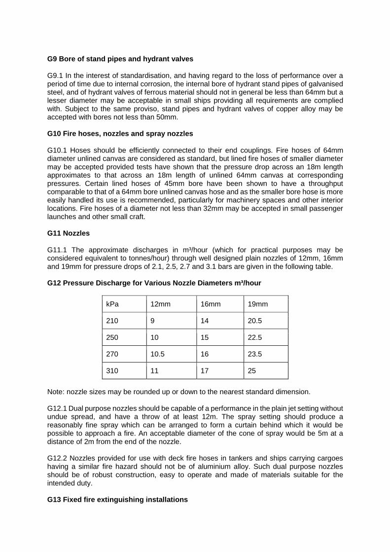
G9 Bore of stand pipes and hydrant valves G9.1 In the interest of standardisation, and having regard to the loss of performance over a period of time due to internal corrosion, the internal bore of hydrant stand pipes of galvanised steel, and of hydrant valves of ferrous material should not in general be less than 64mm but a lesser diameter may be acceptable in small ships providing all requirements are complied with. Subject to the same proviso, stand pipes and hydrant valves of copper alloy may be accepted with bores not less than 50mm. G10 Fire hoses, nozzles and spray nozzles G10.1 Hoses should be efficiently connected to their end couplings. Fire hoses of 64mm diameter unlined canvas are considered as standard, but lined fire hoses of smaller diameter may be accepted provided tests have shown that the pressure drop across an 18m length approximates to that across an 18m length of unlined 64mm canvas at corresponding pressures. Certain lined hoses of 45mm bore have been shown to have a throughput comparable to that of a 64mm bore unlined canvas hose and as the smaller bore hose is more easily handled its use is recommended, particularly for machinery spaces and other interior locations. Fire hoses of a diameter not less than 32mm may be accepted in small passenger launches and other small craft. G11 Nozzles G11.1 The approximate discharges in m³/hour (which for practical purposes may be considered equivalent to tonnes/hour) through well designed plain nozzles of 12mm, 16mm and 19mm for pressure drops of 2.1, 2.5, 2.7 and 3.1 bars are given in the following table. G12 Pressure Discharge for Various Nozzle Diameters m³/hour
kPa 12mm 16mm 19mm
210 9 14 20.5
250 10 15 22.5
270 10.5 16 23.5
310 11 17 25
Note: nozzle sizes may be rounded up or down to the nearest standard dimension. G12.1 Dual purpose nozzles should be capable of a performance in the plain jet setting without undue spread, and have a throw of at least 12m. The spray setting should produce a reasonably fine spray which can be arranged to form a curtain behind which it would be possible to approach a fire. An acceptable diameter of the cone of spray would be 5m at a distance of 2m from the end of the nozzle. G12.2 Nozzles provided for use with deck fire hoses in tankers and ships carrying cargoes having a similar fire hazard should not be of aluminium alloy. Such dual purpose nozzles should be of robust construction, easy to operate and made of materials suitable for the intended duty. G13 Fixed fire extinguishing installations
G13.1 For the periodic inspection, testing and maintenance of transportable gas containers (excluding dissolved acetylene containers) reference should be made to BS 5430: Part 2: 1990. G13.2 The following extract from the "Report of the Home Office Gas Cylinders and Containers Committee" should also be taken into account: Testing of containers used for firefighting, in some cases such as containers filled with carbon dioxide, the containers may remain charged for long periods and are unlikely to deteriorate seriously if filled with dry gas and kept under suitable conditions. It is not considered advisable that these containers should remain charged for indefinite periods without examination and test. It is however considered unreasonable that they should be discharged every five years in order to be submitted to the examination and test which we have recommended. We accordingly recommend that for these containers the first examination and test, after initial manufacturing test, should not be mandatory for new containers until a period of ten years (twenty years in cases where an external examination of the containers is carried out by a competent person at intervals not greater than one year) has elapsed from the time of installation. This relaxation would not apply to any container which had been discharged, showed a loss of pressure or weight or was excessively corroded externally. If, after the first periodic examination and test, containers are found to be in a satisfactory condition then the inspecting authority should certify that they may continue in service for a further period of ten years before being again submitted to examination and test, subject to the exceptions mentioned above. Subsequently the containers should be examined and tested at intervals of five years. G14 In every passenger ship at least one portable fire extinguisher should be provided for use in each control station. G15 In every passenger ship there should be provided on each deck below the bulkhead deck a sufficient number of portable fire extinguishers so that at least two are be readily available for use in every accommodation space, service space and control station between main vertical zones. In enclosed accommodation spaces, service spaces and control stations above the bulkhead deck at least one such extinguisher should be provided for use on each side of the ship in such spaces. The number of such extinguishers in such spaces should not be less than five in a ship of 1,000 tons or over. In addition at least one portable fire extinguisher and a fire blanket should be provided in every galley; provided that where the deck area of any galley exceeds 45m², at least two such extinguishers and two such blankets should be provided. G16 One of the portable fire extinguishers intended for use in any space should be available near the entrance to that space. G17 Fire extinguishers G17.1 The extinguishers should be examined annually by a competent person. During these examinations plastic collars etc. which may conceal the condition of the steel underneath should be removed. G17.2 Each extinguisher should be provided with a sign indicating it has been examined. G17.3 Containers of permanently pressurised and non-permanently pressurised fire extinguishers should be hydraulically pressure tested every 10 years. G17.4 In the corridors of the accommodation area the fire extinguishers should be located as follows: G17.4.1 Passenger ships:
Within each deck and main vertical zone the extinguishers should be so located that no point in the space is more than 15m walking distance from an extinguisher; G17.4.2 Cargo ships: one extinguisher on each deck. G18 General G18.1 The general requirements for fire extinguishers are contained in the relevant Regulations and in BS EN3 Series: 1996, in respect of portable extinguishers. In view of the ability of aluminium to produce incentive smears on steel, aluminium fire extinguishers should not be provided for use on tankers and ships carrying similar flammable cargoes, or which carry vehicles with petrol in their tanks. G19 Charges G19.1 Ships' personnel responsible for them should be informed that the charges of portable and non-portable fire extinguishers should, in general, be checked for condition annually. The charges of extinguishers other than those referred to below should be renewed if on checking there is any indication of deterioration and in any case at intervals not exceeding four years. G19.2 Carbon dioxide extinguishers and gas expellent cartridges of other extinguishers should be recharged or renewed if the loss of gas by weight exceeds 10% of the original charge as stamped on the bottle or cartridge, and the reason for the loss investigated. Spare charges should have the maker's instructions for charging the extinguishers clearly shown and, where the chemicals are liable to deteriorate, the containers should be marked with the date of packing and the date before which renewal is necessary. These spare charges should be supplied either by the makers of the extinguishers or by a firm having an agreement with the makers guaranteeing to supply charges to the original specification. G19.3 Dry powder extinguishers may suffer from compaction when subject to vibration. At least one should be discharged annually and the retention of contents checked. Where the retention is found to be in excess of 15% of the initial charge, further extinguishers should be discharged. G19.4 The portable extinguishers provided for machinery spaces must be of a type which discharges a medium suitable for extinguishing oil fires. Portable extinguishers required in the firing spaces and at the oil fuel installations of motor ships having auxiliary oil-fired boilers need not, in general, be additional to similar extinguishers already provided in the combined spaces to meet other Regulations. Where a heating boiler of less than 73.2 kW is installed, one or more of the portable extinguishers already provided in the space should be so positioned as to be readily available for use at the boiler. Where such a heating boiler is located outside the machinery space paragraph G19.5 below applies. G19.5 Particular attention should be given to positioning portable fire extinguishers in periodically unattended machinery spaces. Generally, a number of extinguishers should be sited at, or adjacent to, the entrance to such spaces having regard to the possible need to attack a fire from outside the space as well as from inside. G19.6 In galleys which are fitted with oil-fired, gas-fired or electric cooking appliances, and in spaces in which oil-fired or gas-fired domestic boilers are fitted, a sufficient number of portable extinguishers should be provided. The types discharging foam, CO² or dry powder will be
found most suitable for dealing with oil fires and CO² or dry powder for fires at electrical cooking appliances and electrical switchboards G19.7 Extinguishers of less than 5 kg capacity, provided in addition to regulation requirements, for use in special positions in service spaces e.g. radio room, switchboards, etc. may be accepted provided they comply with the relevant British Standard specifications. G19.8 The number of such extinguishers in accommodation, cargo and service spaces should not be less than five in passenger ships of 1,000 tons or over. In addition at least one portable fire extinguisher and a fire blanket should be provided in every galley. G19.9 Every cargo ship of 500 tons or over should be provided with a sufficient number of portable fire extinguishers to ensure that at least one such extinguisher will be readily available for use in any part of the accommodation spaces, service spaces and control stations. The number of such extinguishers should not be less than five in a ship of 1,000 tons or over and not less than three in a ship of 500 tons or over but under 1,000 tons. G19.10 Non-portable foam, carbon dioxide and dry powder fire extinguishers provided in compliance with these Regulations shall be of approved types and designs and shall meet the requirements of Schedules 2, 3 and 4 in Merchant Shipping Notice MSN 1665 respectively. G19.11 Portable fire extinguishers provided in compliance with these Regulations shall be approved to the Marine Equipment Directive and be wheelmarked. G19.12 The number of spare charges for vessels operating on short sea routes may be reduced where arrangements have been made for the ready availability of spare extinguishers or charges. Equivalence may be granted only while the vessel is in service on the designated route, an arrangement is made with an identified reputable supplier and the arrangements for supply of spares can be verified. G19.13 Dry powder extinguishers should not exceed one half of the total number of extinguishers in either the accommodation spaces or machinery spaces. Flag-in vessels which have only dry powder should, when extinguishers need replacement, replace with foam extinguishers in accordance with this guidance. G20 Smothering gas installations G20.1 Any gas used as a fire smothering medium in cargo spaces and in boiler and machinery spaces must not either by itself or under expected conditions of use, give off toxic or anaesthetic vapours such as to endanger persons. Gases carried in liquid form should, after discharge into the space for which they are provided, readily evaporate into the gaseous form. G21 Carbon Dioxide systems G21.1 Gas cylinders should be constructed in accordance with the BS 5396: 1976 which requires inter alia the tare weight and the water capacity to be stamped on it. The weight of CO² permitted in each cylinder should not exceed two-thirds of a kilogram for every litre of water capacity of the cylinder at 15ºC. Each cylinder head discharge valve assembly must be fitted with a bursting disc guaranteed to rupture at a pressure of between 177 and 193 bar. The arrangements should permit the free escape of gas from a cylinder when the bursting disc is ruptured but non-return valves should be provided in the discharge system to allow any cylinder or flexible discharge pipe to be disconnected without affecting the use of other cylinders in the system and to prevent any discharge to the CO² cylinder storage room when the system is put into operation to smother a fire. Cylinder head discharge valves, if arranged
for remote release should be capable of being opened manually in the event of malfunction of the remote release system. G22 Carbon Dioxide storage rooms G22.1 The Carbon Dioxide storage rooms should provide access from the open deck in an emergency for personnel wearing breathing apparatus, be well illuminated, dry and well ventilated and there should be no risk to personnel from leakage or from bursting disc rupture. The storage rooms should not be accessible directly from boiler, machinery, accommodation or cargo spaces. The space should be reserved solely for the purpose of the CO² fire extinguishing system. The ambient temperature should not exceed 60ºC and where adjacent spaces are likely to be at higher temperatures, special precautions such as insulation of boundaries or power assisted ventilation should be provided to prevent the overheating. Suitable means should be provided for the cylinders to be weighed as necessary. Attention is drawn to the inability of liquid level detectors to operate satisfactorily when the ambient temperature is near or above the critical temperature which for CO² is 30.5ºC. The space should permit inspection, testing, maintenance and operation of the system to be carried out easily and safely. G22.2 As the discharge must be maintained from the liquid content of the cylinder a suitable internal pipe must be fitted for this purpose. Cylinders fitted with such internal pipes should be marked such that they can be easily distinguished from CO² cylinders not fitted with an internal pipe and used for refrigeration purposes. It should be noted that small CO² cylinders used for providing the control gas for gas operated discharge systems are not provided with internal pipes. G23 Distribution and release arrangements and test requirements G23.1 The distribution valves should be of quick opening type to avoid wire drawing and consequent freezing. All power and automatically operated valves should be capable of being manually controlled from a local position in case of malfunction. Where gas pressure from pilot cylinders is used as a means of releasing the remaining cylinders at least two such cylinders should be used simultaneously for such operation. Effective safeguards should be provided against the gas being accidentally released when a CO² system is being serviced on board and to guard against the inadvertent, and as far as practicable, the malicious use of the controls after the system has been installed or serviced. To achieve this the discharge of CO² from the storage cylinders should be isolated from the machinery space by means of a sector valve and so arranged that the control cabinet door cannot be closed unless the sector valve is in the fully closed position. In installations where the sector valves are gas operated equivalent means of safeguarding the system against inadvertent discharge should be provided on the actuation position. The release arrangements should give an indication if the system has been operated. Automatic time delays should not be incorporated in any of the release arrangements for the system. G23.2 Distribution piping systems should be of a permanent character and arranged so that CO² is effectively distributed throughout the protected spaces through suitably designed nozzles. The arrangements should be such that part of the charge is distributed below the floor plates and over the tank top. G23.3 The Regulations require that 85% of the required concentrations for machinery spaces and cargo pump rooms is achieved in such spaces within two minutes. However the arrangements should additionally provide for a discharge of at least 50% of the required amount of gas in the first minute of operation. Nozzle sizes determined in accordance with BS 5306: Part 4: 2001 are acceptable provided full details are submitted to enable the designs to be checked against the formulae in the British Standard. Otherwise surveyors may accept
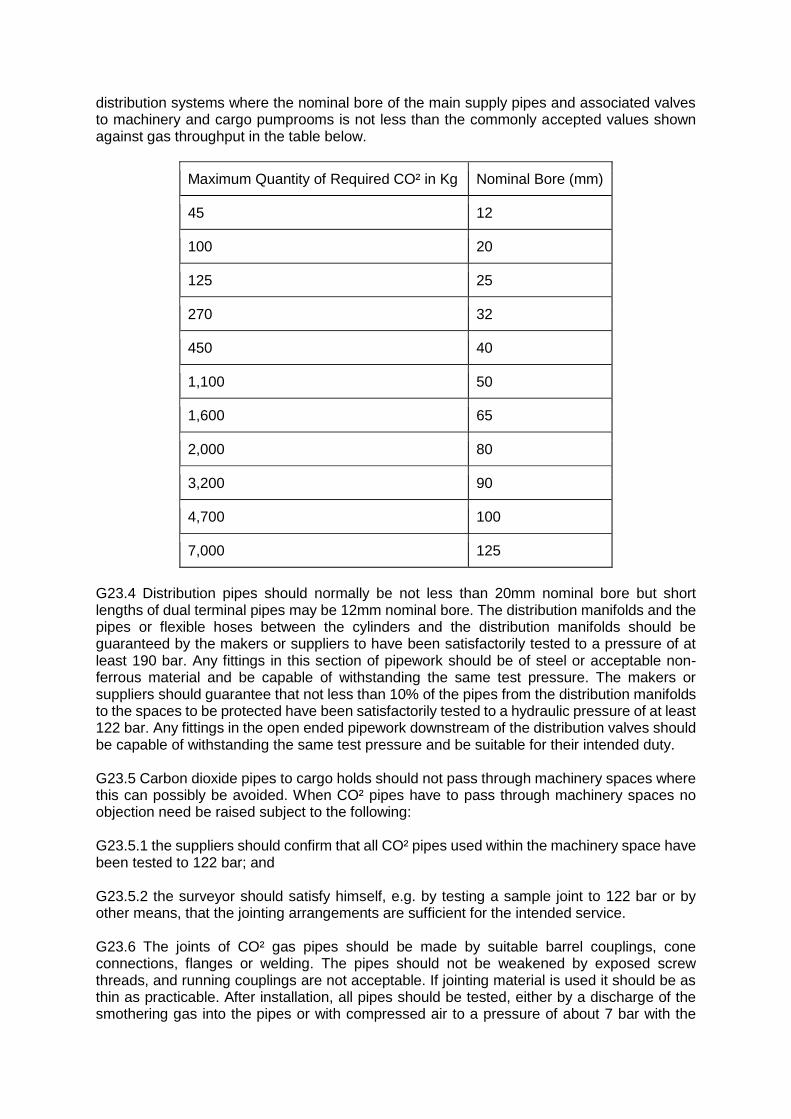
distribution systems where the nominal bore of the main supply pipes and associated valves to machinery and cargo pumprooms is not less than the commonly accepted values shown against gas throughput in the table below.
Maximum Quantity of Required CO² in Kg Nominal Bore (mm)
45 12
100 20
125 25
270 32
450 40
1,100 50
1,600 65
2,000 80
3,200 90
4,700 100
7,000 125
G23.4 Distribution pipes should normally be not less than 20mm nominal bore but short lengths of dual terminal pipes may be 12mm nominal bore. The distribution manifolds and the pipes or flexible hoses between the cylinders and the distribution manifolds should be guaranteed by the makers or suppliers to have been satisfactorily tested to a pressure of at least 190 bar. Any fittings in this section of pipework should be of steel or acceptable non-ferrous material and be capable of withstanding the same test pressure. The makers or suppliers should guarantee that not less than 10% of the pipes from the distribution manifolds to the spaces to be protected have been satisfactorily tested to a hydraulic pressure of at least 122 bar. Any fittings in the open ended pipework downstream of the distribution valves should be capable of withstanding the same test pressure and be suitable for their intended duty. G23.5 Carbon dioxide pipes to cargo holds should not pass through machinery spaces where this can possibly be avoided. When CO² pipes have to pass through machinery spaces no objection need be raised subject to the following: G23.5.1 the suppliers should confirm that all CO² pipes used within the machinery space have been tested to 122 bar; and G23.5.2 the surveyor should satisfy himself, e.g. by testing a sample joint to 122 bar or by other means, that the jointing arrangements are sufficient for the intended service. G23.6 The joints of CO² gas pipes should be made by suitable barrel couplings, cone connections, flanges or welding. The pipes should not be weakened by exposed screw threads, and running couplings are not acceptable. If jointing material is used it should be as thin as practicable. After installation, all pipes should be tested, either by a discharge of the smothering gas into the pipes or with compressed air to a pressure of about 7 bar with the
discharge opening closed to ensure no leaking will occur. There should be no permanent connections between the CO² system and any compressed air system. After the pressure tests have been completed, it should be ensured that all plugs and blank flanges have been removed from the distribution system and that all pipes are clear and correctly connected according to the marking on the distribution valve chest. G24 Operation and instructions G24.1 Instructions for operating the installation must be displayed near the remote operating controls, distribution control valves and also near the gas cylinders. Such instructions should state that when the remote release controls are used, the cylinder storage room should be checked to confirm that the medium has been discharged. When the installation is used to protect the pump room or cargo tanks of a tanker and similar spaces, a notice should be displayed indicating that the system should not be used for inerting purposes unless the compartment is gas free since the injection of CO² may generate a static charge capable of igniting flammable atmospheres. G24.2 When the means for putting the system into operation are located within a compartment which may be locked, e.g. the CO² cylinder room, one key to such a compartment should be provided adjacent to the entrance in a suitably marked glass-fronted box. Normally, mechanical ventilation of the protected space should be capable of being shut down manually. Where this is achieved automatically on release of CO², over ride facilities that can be rapidly operated without entry into the protected space should be provided to enable spaces to be ventilated after the injection of CO². Suitable notices should be posted by the ventilation system controls to indicate that provisions for automatic ventilation shut down have been fitted and where these are located. Notices should be posted on the entrances to every space protected by CO² indicating that the space is so protected and that personnel should evacuate the space immediately on hearing the CO² alarm. G25 Alarms G25.1 The means provided for giving audible alarm referred to in the Regulations should be distinct from all other alarms. When such means are electric, the power should be obtained from the emergency source batteries or through the emergency switchboard. Supplies for air operated devices should be taken from the main air receivers through a safeguarded supply system. When fitted in pump rooms, such alarms if electric should be intrinsically safe and if of the air operated type should be connected to a safeguarded moisture free supply. The arrangements should be such that the alarm is given automatically before the release of CO². Interlocks or time delays to delay operation of the release mechanisms are not acceptable. G26 Exhaust ducts from galley ranges G26.1 When CO² is to be used as the fixed means of extinguishing fires in galley ducts, the following criteria are recommended: G26.1.1 the system should comply with the appropriate recommendations set out in NFPA 12: 2000 (Standards on CO² Extinguishing Systems); G26.1.2 the recommended flooding factor should be 2 kg/m³ of duct volume, representing a concentration of 65%; and G26.1.3 the duct must be designed to withstand the calculated pressure which will occur within the duct after discharge of the gas, with the dampers closed. G27 Bulk CO² systems
G27.1 In systems in which refrigerated liquid CO² stored in bulk is utilised the design of the storage vessel and details of the relief devices, fittings, instrumentation and control equipment, together with details and specifications of the distribution pipework arrangements should have been approved by or on behalf of the MCA and for which a certificate of approval has been issued. G27.2 The total charge must not be less than regulation capacity and may be contained in more than one tank. Because the availability of bulk CO² on a world-wide basis may be uncertain and that the inability to make good any leakage may cause the ship to be considered unseaworthy, the MCA recommends that about 5% additional capacity be provided. G27.3 The number of CO² leakage paths should be kept to a minimum and be monitored with audible and visual alarms where necessary. G27.4 Refrigerating units should be duplicated and arranged for automatic standby duties. G27.5 An automatic alarm should be fitted to operate at not more than 2% loss of contents. G27.6 Duplicate means of ascertaining contents measurements should be fitted or supplied. G27.7 Alarm systems should be powered from two sources, one of which should be the emergency source of electrical power. G27.8 One complete refrigerating unit should be powered by the emergency source of power; cooling water to condensers may be obtained from the emergency fire pump through temporary connections from the fire main. G27.9 Relief valve arrangements should be in duplicate on a changeover valve assembly to permit replacements in service, means being provided to ensure that at least one relief valve is in communication with the tank. The discharge should be led to a safe place outside the room in which the tank is situated. Alternative proposals will be considered on their merits. G28 Distribution and test requirement G28.1 Distribution and test requirements should generally follow the instructions for high pressure systems except that the piping sizes given for guidance in G10.23.3 are too small for the discharge rates required by regulation in the case of bulk systems due to the lower initial pressure in the storage containers. Full details of the distribution pipe which should comply with the requirements of BS 5306: Part 4: 2001 or equivalent should be submitted to MCA Headquarters for consideration. G29 Foam installations G29.1 As the present tendency in machinery space arrangements is to site items of machinery on flats, especially in vessels having aft engine room installations, the arrangements for distributing foam in connection with oil-fired boilers, oil fuel units, etc. should be considered in relation to the possibility of fire spreading from one place to another or of oil spraying from a burst pipe being ignited. Means should be provided for foam to be effectively directed by fixed sprayers on to the main fire hazards. Sufficient foam should be provided to cover to a depth of 150mm all areas over which oil is liable to spread. G29.2 The provision of coamings in way of boilers, diesel generators etc. whilst preventing the spread of fire in some instances, cannot always be guaranteed to do so, e.g. oil spraying from leaking flanges, and the flats on which such items are situated should therefore be
protected by the foam installation and their areas included with the tank top area in the assessment of the required quantity of foam. The emergency fire pump capacity should be suitably increased if it is necessary to maintain water supply from that source. Distribution pipes should in general be of steel, galvanised inside and outside, and provision for flushing with fresh water should be incorporated. G30 Non-portable extinguishers in machinery spaces G30.1 The length of hose on non-portable extinguishers should not in general exceed that provided by the makers except where the lengthening of the hose will not reduce the projection of the froth below the distance specified in the Regulations, i.e. 14m for extinguishers of 135l and over, and 10m for extinguishers of under 135l. Non-portable dry powder extinguishers are not acceptable as the equivalents of non-portable carbon dioxide or foam extinguishers. No objection need be raised to their acceptance as additional equipment. When used in conjunction with foam equipment the powder used should be of a foam compatible type. G30.2 It is recommended that non-portable extinguishers be secured by a band type bracket fitted in halves round the body of the extinguisher with a non-corrodible hinge and securing pin. Whatever method is chosen to secure the extinguisher, it should be capable of ready release without the use of tools. G30.3 Because of the deterioration to which the ingredients of foam making liquids are liable at temperatures of 38ºC or over, portable foam fire extinguishers should be kept in as cool a place as possible. Additionally, they should not be stowed in a position where the ambient temperature is liable to fall below 0ºC. Dry powder and CO² extinguishers are generally considered suitable for use at temperatures down to -30ºC, but the latter type should not be exposed to corrosive conditions or to a temperature exceeding 60ºC. The extinguishing media provided adjacent to any given fire risk should be suitable for the type of fire risk involved. G31 Automatic sprinkler systems G31.1 Paragraph 2.3.3.2 of Chapter 8 of the FSS Code - the nominal area is defined as being the gross, horizontal projection of the area to be covered. G31.2 Instructions for carrying out of periodic tests should be exhibited prominently at the control station. G32 Deep fat fryer standards G32.1 Deep fat fryers are included in the Marine Equipment Directive and on UK ships should be so approved and wheel marked. G33 Fire extinguishing arrangements in cargo spaces G33.1 For vessels described in paragraph 7.1.3 and carrying Cargoes listed in table 2 of MSC Circular 671 and for which a fixed gas system is ineffective, the cargo space shall be provided with an approved fire extinguishing system which can be shown to give equivalent fire protection. G34 Deck foam systems G34.1 Foam mains should be routed clear of tanker pump rooms. When this is impracticable details of alternative arrangements should be submitted for consideration.
G34.2 In any chemical tanker the type of foam concentrate should be appropriate for the chemicals listed on the Certificate of Fitness i.e. either a regular foam or an alcohol resistant foam. In cases where a foam concentrate of each type is required an all-purpose foam should be used. G35 The adjustable safety belt or harness together with the snap hook should be to BS EN 354, 355, 358, 361 and 365 requirements. To ensure that the safety belt or harness is compatible with the breathing apparatus, each type of safety belt or harness supplied by the manufacturers should be submitted for the drop test at the same time as the apparatus is submitted for approval. G36 The point of attachment of the life and signalling line to the safety belt or harness should be such as to be easily removable by the wearer. Where it is necessary to use a pennant for this purpose the attachment of pennant to the safety harness should be such that it cannot readily be detached. Snap hooks should be of materials so far as possible resistant to incendive sparking on impact. G37 The firemen's outfits required by the Regulations should be stowed in readily accessible positions which are not likely to be easily cut off by fire. G38 Air compressors G38.1 Where special compressors intended solely for the charging of compressed air cylinders are carried on board, surveyors should ensure that they are of adequate capacity and that the air intakes are sited so as to preclude the ingress of water or noxious fumes, even under adverse weather conditions. Also the vessel's standing orders should contain the manufacturer's detailed instructions for operating and servicing the compressor and ancillary equipment, e.g. filters, dryers, etc. At least one member of the crew should be competent in the use of the equipment. G39 Marking G39.1 Where in any ship breathing apparatus cylinders are carried having different working pressures, in addition to the normal marking on the cylinder the working pressure should be prominently marked in paint on the cylinder. G40 Training G40.1 In addition to the fully charged spare cylinders required by the Regulations it is recommended that where no means for recharging such cylinders is provided additional cylinder capacity be provided for training purposes. Cylinders intended for such purposes should be prominently marked to indicate their intended use, e.g. by the use of waterproof adhesive labels or tape. G41 Safety lamps G41.1 They may be either the hand lamp or cap-lamp type. The batteries must be re-chargeable and the hand lamps must be fitted with means for easy attachment of the lamp to the user at about waist level. G41.2 Safety lamps for use with firemen's outfits they should be Class I. These lamps are intended for use in any ship, including those carrying cargoes which are, or may give rise to, flammable gases and vapours. All lamps accepted in this Class are suitable for use in petroleum tankers but may not be suitable for all flammable cargoes; special attention should

be paid to ensure that certification is suitable for use with the cargoes of bulk chemical carriers and liquefied gas carriers.