Embed Size (px)
Citation preview
AU306 MANUFACTURING PROCESS - I: PART – C
M.K.Ravishankar, Associate Professor, AED, MCE, Hassan – 573 201. 54
7. Special Casting Processes
Shell molding, Precision investment casting, Die casting, Centrifugal casting, Continuous casting.
Classification of casting Processes
Casting processes can be classified into following FOUR categories:
1. Conventional Molding Processes
a) Green Sand Molding
b) Dry Sand Molding
c) Flask less Molding
2. Chemical Sand Molding Processes
a) Shell Molding
b) Sodium Silicate Molding
c) No-Bake Molding
3. Permanent Mold Processes
a) Gravity Die casting
b) Low and High Pressure Die Casting
4. Special Casting Processes
a) Lost Wax
b) Ceramics Shell Molding
c) Evaporative Pattern Casting
d) Vacuum Sealed Molding
e) Centrifugal Casting
a) Green Sand Molding
Green sand molding is the most diversified molding method used in metal casting operations.
The process utilizes a mold made of compressed or compacted moist sand.
The term "green" denotes the presence of moisture in the molding sand.
The mold material consists of silica sand mixed with a suitable bonding agent (usually clay) and
moisture.
AU306 MANUFACTURING PROCESS - I: PART – C
M.K.Ravishankar, Associate Professor, AED, MCE, Hassan – 573 201. 55
Advantages: Disadvantages:
Most metals can be cast by this method.
Pattern costs and material costs are
relatively low.
No Limitation with respect to size of casting
and type of metal or alloy used
Surface Finish of the castings obtained by this
process is not good and machining is often
required to achieve the finished product.
b) Dry Sand Molding
When it is desired that the gas forming materials are lowered in the molds, air-dried molds are
sometimes preferred to green sand molds. Two types of drying of molds are often required.
1. Skin drying and
2. Complete mold drying.
In skin drying a firm mold face is produced. Shakeout of the mold is almost as good as that
obtained with green sand molding.
The most common method of drying the refractory mold coating uses hot air, gas or oil flame
Skin drying of the mold can be accomplished with the aid of torches, directed at the mold
surface.
Sand Mold Making Procedure
The procedure for making mold of a cast iron wheel is shown in figure 7 (a), (b), (c).
• The first step in making mold is to place the pattern on the molding board.
• The drag is placed on the board (Figure 7 (a)).
• Dry facing sand is sprinkled over the board and pattern to provide a non sticky layer.
• Molding sand is then riddled in to cover the pattern with the fingers; then the drag is completely
filled.
• The sand is then firmly packed in the drag by means of hand rammers. The ramming must be
proper i.e. it must neither be too hard or soft.
• After the ramming is over, the excess sand is leveled off with a straight bar known as a strike
rod.
• With the help of vent rod, vent holes are made in the drag to the full depth of the flask as well
as to the pattern to facilitate the removal of gases during pouring and solidification.

AU306 MANUFACTURING PROCESS - I: PART – C
M.K.Ravishankar, Associate Professor, AED, MCE, Hassan – 573 201. 56
• The finished drag flask is now rolled over to the bottom board exposing the pattern.
• Cope half of the pattern is then placed over the drag pattern with the help of locating pins. The
cope flask on the drag is located aligning again with the help of pins ( Figure 7(b)).
• The dry parting sand is sprinkled all over the drag and on the pattern.
• A sprue pin for making the sprue passage is located at a small distance from the pattern. Also,
riser pin, if required, is placed at an appropriate place.
• The operation of filling, ramming and venting of the cope proceed in the same manner as
performed in the drag.
• The sprue and riser pins are removed first and a pouring basin is scooped out at the top to
pour the liquid metal.
• Then pattern from the cope and drag is removed and facing sand in the form of paste is
applied all over the mold cavity and runners which would give the finished casting a good
surface finish.
The mold is now assembled. The mold now is ready for pouring (Figure 7 (c))
Figure 7 (a)
Figure 7 (b)
Figure 7 (c)
AU306 MANUFACTURING PROCESS - I: PART – C
M.K.Ravishankar, Associate Professor, AED, MCE, Hassan – 573 201. 57
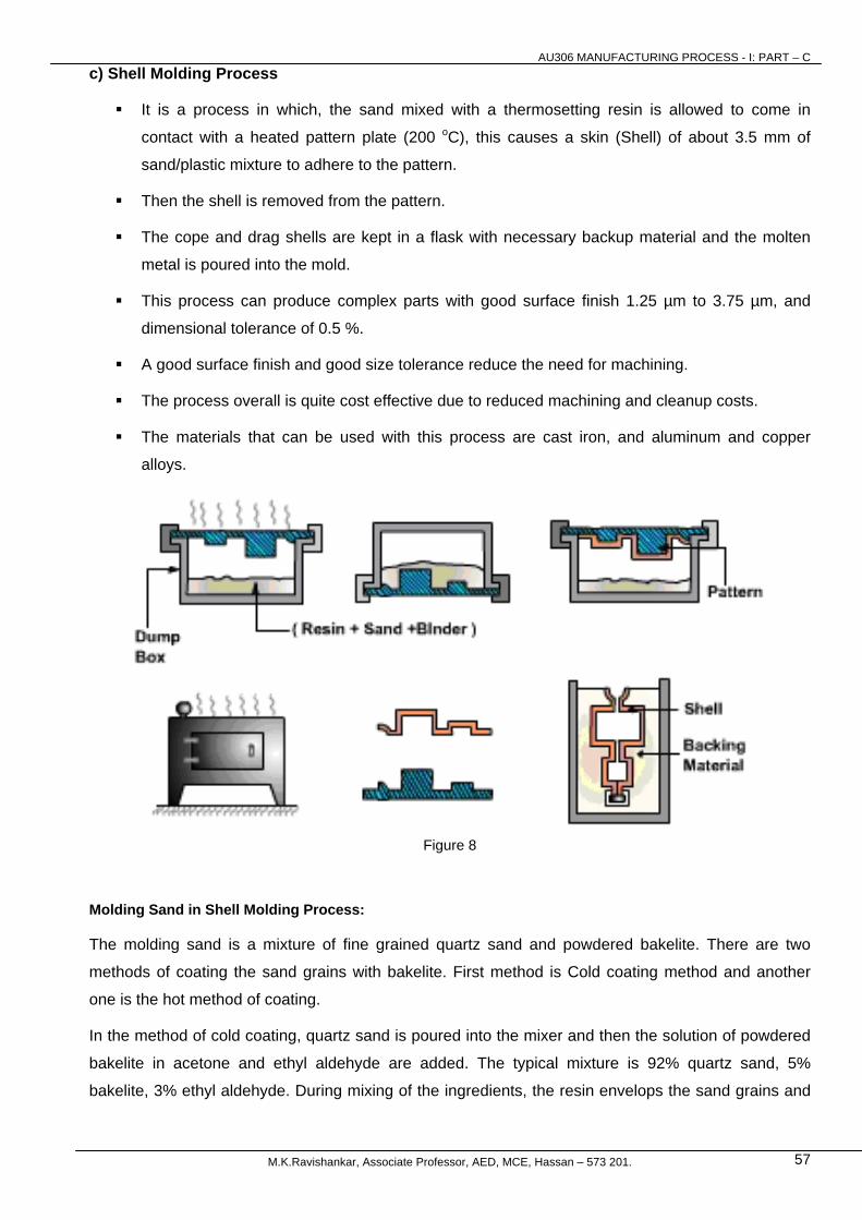
c) Shell Molding Process
It is a process in which, the sand mixed with a thermosetting resin is allowed to come in
contact with a heated pattern plate (200 oC), this causes a skin (Shell) of about 3.5 mm of
sand/plastic mixture to adhere to the pattern.
Then the shell is removed from the pattern.
The cope and drag shells are kept in a flask with necessary backup material and the molten
metal is poured into the mold.
This process can produce complex parts with good surface finish 1.25 µm to 3.75 µm, and
dimensional tolerance of 0.5 %.
A good surface finish and good size tolerance reduce the need for machining.
The process overall is quite cost effective due to reduced machining and cleanup costs.
The materials that can be used with this process are cast iron, and aluminum and copper
alloys.
Figure 8
Molding Sand in Shell Molding Process:
The molding sand is a mixture of fine grained quartz sand and powdered bakelite. There are two
methods of coating the sand grains with bakelite. First method is Cold coating method and another
one is the hot method of coating.
In the method of cold coating, quartz sand is poured into the mixer and then the solution of powdered
bakelite in acetone and ethyl aldehyde are added. The typical mixture is 92% quartz sand, 5%
bakelite, 3% ethyl aldehyde. During mixing of the ingredients, the resin envelops the sand grains and
AU306 MANUFACTURING PROCESS - I: PART – C
M.K.Ravishankar, Associate Professor, AED, MCE, Hassan – 573 201. 58
the solvent evaporates, leaving a thin film that uniformly coats the surface of sand grains, thereby
imparting fluidity to the sand mixtures.
In the method of hot coating, the mixture is heated to 150-1800C prior to loading the sand. In the
course of sand mixing, the soluble phenol formaldehyde resin is added. The mixer is allowed to cool
up to 80 – 900C. This method gives better properties to the mixtures than cold method.
d) Sodium Silicate Molding Process
In this process, the refractory material is coated with a sodium silicate-based binder. For molds, the
sand mixture can be compacted manually, jolted or squeezed around the pattern in the flask. After
compaction, CO2 gas is passed through the core or mold. The CO2 chemically reacts with the sodium
silicate to cure, or harden, the binder. This cured binder then holds the refractory in place around the
pattern. After curing, the pattern is withdrawn from the mold.
The sodium silicate process is one of the most environmentally acceptable of the chemical processes
available. The major disadvantage of the process is that the binder is very hygroscopic and readily
absorbs water, which causes a porosity in the castings.. Also, because the binder creates such a
hard, rigid mold wall, shakeout and collapsibility characteristics can slow down production. Some of
the advantages of the process are:
• A hard, rigid core and mold are typical of the process, which gives the casting good
dimensional tolerances;
• good casting surface finishes are readily obtainable;
e) Permanent Mold Process
In all the above processes, a mold need to be prepared for each of the casting produced. For
large-scale production, making a mold, for every casting to be produced, may be difficult and
expensive.
Therefore, a permanent mold, called the die may be made from which a large number of
castings can be produced; the molds are usually made of cast iron or steel, although graphite,
copper and aluminum have been used as mold materials.
The process in which we use a die to make the castings is called permanent mold casting or
gravity die casting, since the metal enters the mold under gravity.
Some time in die-casting we inject the molten metal with a high pressure. When we apply
pressure in injecting the metal it is called pressure die casting process.
AU306 MANUFACTURING PROCESS - I: PART – C
M.K.Ravishankar, Associate Professor, AED, MCE, Hassan – 573 201. 59
Advantages: Disadvantages:
Permanent Molding produces a sound dense casting
with superior mechanical properties.
The castings produced are quite uniform in shape,
have a higher degree of dimensional accuracy than
castings produced in sand
The permanent mold process is also capable of
producing a consistent quality of finish on castings
The cost of tooling is usually higher than
for sand castings
The process is generally limited to the
production of small castings of simple
exterior design, although complex
castings such as aluminum engine
blocks and heads are now commonplace
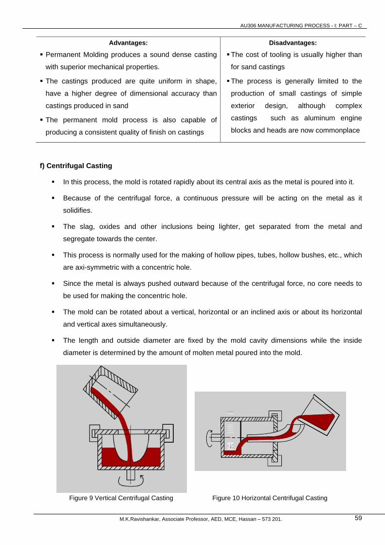
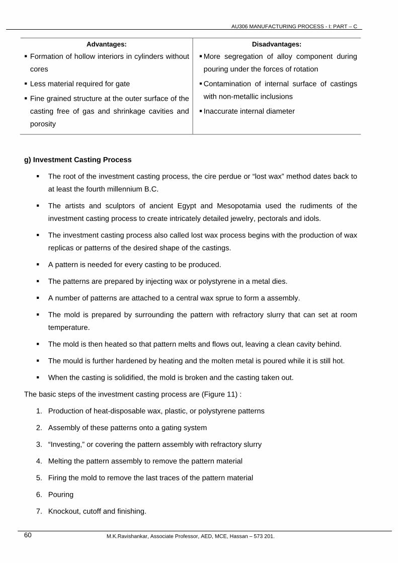
f) Centrifugal Casting
In this process, the mold is rotated rapidly about its central axis as the metal is poured into it.
Because of the centrifugal force, a continuous pressure will be acting on the metal as it
solidifies.
The slag, oxides and other inclusions being lighter, get separated from the metal and
segregate towards the center.
This process is normally used for the making of hollow pipes, tubes, hollow bushes, etc., which
are axi-symmetric with a concentric hole.
Since the metal is always pushed outward because of the centrifugal force, no core needs to
be used for making the concentric hole.
The mold can be rotated about a vertical, horizontal or an inclined axis or about its horizontal
and vertical axes simultaneously.
The length and outside diameter are fixed by the mold cavity dimensions while the inside
diameter is determined by the amount of molten metal poured into the mold.
Figure 9 Vertical Centrifugal Casting Figure 10 Horizontal Centrifugal Casting
AU306 MANUFACTURING PROCESS - I: PART – C
M.K.Ravishankar, Associate Professor, AED, MCE, Hassan – 573 201. 60
Advantages: Disadvantages:
Formation of hollow interiors in cylinders without
cores
Less material required for gate
Fine grained structure at the outer surface of the
casting free of gas and shrinkage cavities and
porosity
More segregation of alloy component during
pouring under the forces of rotation
Contamination of internal surface of castings
with non-metallic inclusions
Inaccurate internal diameter
g) Investment Casting Process
The root of the investment casting process, the cire perdue or “lost wax” method dates back to
at least the fourth millennium B.C.
The artists and sculptors of ancient Egypt and Mesopotamia used the rudiments of the
investment casting process to create intricately detailed jewelry, pectorals and idols.
The investment casting process also called lost wax process begins with the production of wax
replicas or patterns of the desired shape of the castings.
A pattern is needed for every casting to be produced.
The patterns are prepared by injecting wax or polystyrene in a metal dies.
A number of patterns are attached to a central wax sprue to form a assembly.
The mold is prepared by surrounding the pattern with refractory slurry that can set at room
temperature.
The mold is then heated so that pattern melts and flows out, leaving a clean cavity behind.
The mould is further hardened by heating and the molten metal is poured while it is still hot.
When the casting is solidified, the mold is broken and the casting taken out.
The basic steps of the investment casting process are (Figure 11) :
1. Production of heat-disposable wax, plastic, or polystyrene patterns
2. Assembly of these patterns onto a gating system
3. “Investing,” or covering the pattern assembly with refractory slurry
4. Melting the pattern assembly to remove the pattern material
5. Firing the mold to remove the last traces of the pattern material
6. Pouring
7. Knockout, cutoff and finishing.

AU306 MANUFACTURING PROCESS - I: PART – C
M.K.Ravishankar, Associate Professor, AED, MCE, Hassan – 573 201. 61
Figure 11: The Basic Steps of the Investment Casting Process
AU306 MANUFACTURING PROCESS - I: PART – C
M.K.Ravishankar, Associate Professor, AED, MCE, Hassan – 573 201. 62
8. Defects in Casting and Non-destructive testing (NDT)
Defects in Casting: Causes and remedies, cleaning and inspection of casting-fettling operations,
Non-destructive testing: X-ray radiography, Dye-penetrate test, ultrasonic test, magnetic particle inspection.
Classification of casting defects:
It always difficult to classify casting defects because of the wide range of contributory cause and the
nature of defects. However, casting defects can be broadly classified under the following headings.
a) Based on nature of defects:
i) Surface defects: are visible on the surface of castings such as incorrect shape and size, misrun,
laps, flashes, metal penetration, rat tail, poor surface finish, etc.
ii) Internal defects: are present in the interior of castings and are revealed by non destructive testing
alone. Examples are pin holes, blow hole, slag inclusion, etc.
iii) Incorrect chemical composition which may also result in the formation of undesirable
microstructure.
iv) Un-satisfactory mechanical properties.
b) Based on contributing causes or origins
i) Defects caused by pattern and molding box equipment such as incorrect dimension, poor surface
finish, flash, mismatch etc.
ii) Defects due to improper mold and core and core making. These incude blowholes, drops, scabs,
pinholes, hot tear etc.
iii) Defects caused by improper gating and risering, resulting in cold shut, mistune, sand inclusion, hot
tear, shrinkage cavity etc.
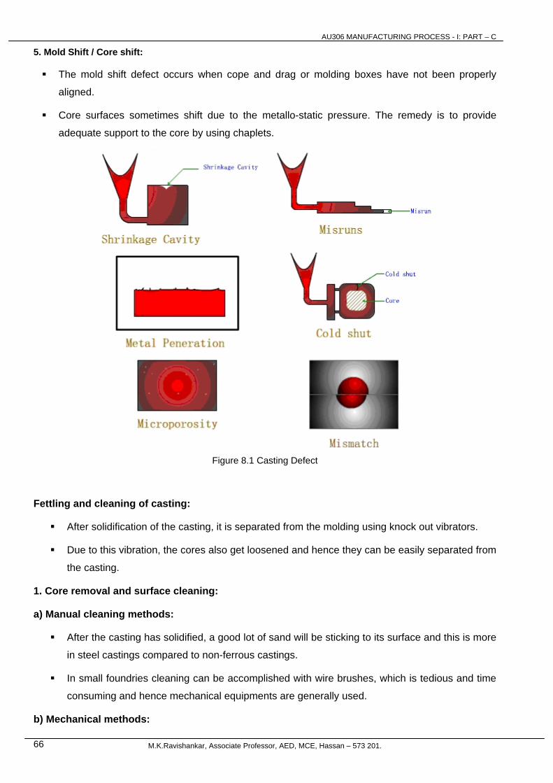
Casting Defects: (Figure 8.1)
The following are the major defects, which are likely to occur in sand castings
1. Gas defects
2. Shrinkage cavities
3. Molding material defects
4. Pouring metal defects
5. Mold shift / Core shift
1. Gas Defects:
A condition existing in a casting caused by the trapping of gas in the molten metal or by mold
gases evolved during the pouring of the casting.
The defects in this category can be classified into
AU306 MANUFACTURING PROCESS - I: PART – C
M.K.Ravishankar, Associate Professor, AED, MCE, Hassan – 573 201. 63
a) Blowholes and
b) Pinhole porosity
Blowholes are spherical or elongated cavities present in the casting on the surface
or inside the casting.
Pinhole porosity occurs due to the dissolution of hydrogen gas, which gets
entrapped during heating of molten metal.
Causes:
The lower gas-passing tendency of the mold, which may be due to lower venting, lower
permeability of the mold or improper design of the casting.
The lower permeability is caused by finer grain size of the sand, high percentage of clay in
mold mixture, and excessive moisture present in the mold.
i) Metal contains gas
ii) Mold is too hot
iii) Poor mold burnout
2. Shrinkage Cavities:
These are caused by liquid shrinkage occurring during the solidification of the casting.
To compensate for this, proper feeding of liquid metal is required.
For this reason risers are placed at the appropriate places in the mold.
Sprues may be too thin, too long or not attached in the proper location, causing shrinkage
cavities.
It is recommended to use thick sprues to avoid shrinkage cavities.
3. Molding Material Defects:
The defects in this category are
i) Cuts and washes
ii) Metal penetration
iii) Fusion, and
iv) Swell
v) Drop
vi) Expansion scabs
i) Cut and washes:

AU306 MANUFACTURING PROCESS - I: PART – C
M.K.Ravishankar, Associate Professor, AED, MCE, Hassan – 573 201. 64
These appear as rough spots and areas of excess metal, and are caused by erosion of
molding sand by the flowing metal.
This is caused by the molding sand not having enough strength and the molten metal flowing
at high velocity.
The former can be taken care of by the proper choice of molding sand and the latter can be
overcome by the proper design of the gating system.
ii) Metal penetration:
When molten metal enters into the gaps between sand grains, the result is a rough casting
surface.
This occurs because the sand is coarse or no mold wash was applied on the surface of the
mold.
The coarser the sand grains more the metal penetration.
iii) Fusion:
This is caused by the fusion of the sand grains with the molten metal, giving a brittle, glassy
appearance on the casting surface.
The main reason for this is that the clay or the sand particles are of lower refractoriness or that
the pouring temperature is too high.
iv) Swell:
Under the influence of metallostatic forces, the mold wall may move back causing a swell in
the dimension of the casting.
A proper ramming of the mold will correct this defect.
v) Drop:
This occurs when some portion of the mold usually from cope surface breaks off and falls into
the mold cavity. Remedy is to ram the sand properly.
vi) Expansion scabs:
These are due to expansion property of sand, that is when molten metal is poured, the sand
will expand due to high temperature.
If this expansion is prevented due to mold condition, it will develop minute cracks and molten
metal may enter these cracks resulting in a poor surface condition in casting.
This may be due to hard ramming of mold, high clay content, low thermal stability of sand
resulting in expansion and low hot deformation of the mold.
The remedy is to reduce clay content, less ramming and use of additives which reduce thermal
expansion but increase hot deformation of sand.
AU306 MANUFACTURING PROCESS - I: PART – C
M.K.Ravishankar, Associate Professor, AED, MCE, Hassan – 573 201. 65
b) Inclusions:
Particles of slag, refractory materials, sand or deoxidation products are trapped in the casting
during pouring solidification.
The provision of choke in the gating system and the pouring basin at the top of the mold can
prevent this defect.
4. Pouring Metal Defects:
The likely defects in this category are
i) Mis-runs and
ii) Cold shuts.
i) Mis-run:
A mis-run is caused when the metal is unable to fill the mold cavity completely and thus leaves
unfilled cavities.
A mis-run results when the metal is too cold to flow to the extremities of the mold cavity before
freezing.
Long, thin sections are subject to this defect and should be avoided in casting design.
ii) Cold shut:
A cold shut is caused when two streams while meeting in the mold cavity, do not fuse together
properly thus forming a discontinuity in the casting.
When the molten metal is poured into the mold cavity through more-than-one gate, multiple
liquid fronts will have to flow together and become one solid.
If the flowing metal fronts are too cool, they may not flow together, but will leave a seam in the
part.
Such a seam is called a cold shut, and can be prevented by assuring sufficient superheat in the
poured metal and thick enough walls in the casting design.
Causes:
The mis-run and cold shut defects are caused either by a lower fluidity of the mold or when the
section thickness of the casting is very small.
Fluidity can be improved by changing the composition of the metal and by increasing the
pouring temperature of the metal.
AU306 MANUFACTURING PROCESS - I: PART – C
M.K.Ravishankar, Associate Professor, AED, MCE, Hassan – 573 201. 66
5. Mold Shift / Core shift:
The mold shift defect occurs when cope and drag or molding boxes have not been properly
aligned.
Core surfaces sometimes shift due to the metallo-static pressure. The remedy is to provide
adequate support to the core by using chaplets.
Figure 8.1 Casting Defect
Fettling and cleaning of casting:
After solidification of the casting, it is separated from the molding using knock out vibrators.
Due to this vibration, the cores also get loosened and hence they can be easily separated from
the casting.
1. Core removal and surface cleaning:
a) Manual cleaning methods:
After the casting has solidified, a good lot of sand will be sticking to its surface and this is more
in steel castings compared to non-ferrous castings.
In small foundries cleaning can be accomplished with wire brushes, which is tedious and time
consuming and hence mechanical equipments are generally used.
b) Mechanical methods:
AU306 MANUFACTURING PROCESS - I: PART – C
M.K.Ravishankar, Associate Professor, AED, MCE, Hassan – 573 201. 67
i) Tumbling:
The components to be cleaned are placed inside a barrel along with hardened steel rods.
The barrel is then rotated about its central axis for a sufficient length of time, so that the
surfaces are cleaned by peening action as castings rub against the steel rods.
ii) Compressed air impact cleaning:
Here, a stream of suitable abrasive particles along with compressed air is directed at high
velocities against the surfaces to be cleaned.
This is done in tightly closed chambers and due to the impact, the surfaces of the castings will
be cleaned.
iii) Mechanical impact cleaning (shot blasting):
The abrasive particles are thrown against surfaces to be cleaned by centrifugal force.
Due to the impact, the surfaces of the castings are cleaned.
iv) Hydroblasting:
In this method, a high velocity stream containing about 15% sand and 85% water is directed
against the surfaces to be cleaned.
Water at a pressure of about 140 atmospheres is supplied to a nozzle so that stream velocities
of upto 6000 m/min are obtained, due to this the minimum weight of the casting cleaned this
way should be at least 120 kg, the jet angled at 450.
Used sand may be reclaimed.
2. Removal of gates and risers:
Several methods are used depending upon the metal, casting size and other conditions. These are,
i) Breaking the gates from the casting
ii) Sawing with hand, disc or hacksaw
iii) Flame cutting with oxyacetylene torch
iv) Cutting with an abrasive cut – off wheel
3. Removal of fins, unwanted projections etc.:
This can be done using methods such as chipping, sawing, flame cutting, grinding etc.
4. Repair of castings:
After the casting is made, sometimes very minute defects may be noticed in the casting which
may not affect its usefulness.
In such cases, these defects are filled up using weld metal etc.
AU306 MANUFACTURING PROCESS - I: PART – C
M.K.Ravishankar, Associate Professor, AED, MCE, Hassan – 573 201. 68
Inspection of castings: can be carried out at various stages as follows –
i) Process inspection:
It is done to detect defects and to allow corrections to be made before the parts hve been
processed i.e., before it is too late.
ii) Visual inspection:
This is the simplest, fastest and most commonly employed method for finding many defects
visually.
It is limited to the defects which can be observed on surfaces.
iii) Dimensional inspection:
First casting to be machined is to be dimensionally checked in the foundry by setting up on a
surface plate with angle plate and measuring instruments such as micrometer, vernier height
gauge, etc. to ensure that the pattern and core boxes used are correct.
iv) Pressure testing:
Castings to be used for containing or conveying liquids or gases have to be tested for leaks
through their walls.
The castings with porosity may leak and leaks may be detected by submerging the complete
casting under water for gas pressures or by virtual inspection for liquid pressures.
v) Destructive testing:
Destructive tests such as tensile, compression, impact, fatigue and creep may be performed
on specimens machined out of the castings to assess the various properties.
vi) Non-destructive testing:
The basic feature of this test is that the parts are inspected for internal and surface defects without
destroying the components. Different methods available
a) Liquid penetrant test
b) Magnetic particle inspection
c) X-ray radiography
d) Ultrasonic inspection
e) Eddy current test
f) Gamma ray radiography

AU306 MANUFACTURING PROCESS - I: PART – C
M.K.Ravishankar, Associate Professor, AED, MCE, Hassan – 573 201. 69
Nondestructive testing:
Nondestructive testing (NDT), also called nondestructive examination (NDE) and nondestructive
inspection (NDI), is testing that does not destroy the test object.
NDE is vital for constructing and maintaining all types of components and structures.
To detect different defects such as cracking and corrosion, there are different methods of testing
available, such as X-ray (where cracks show up on the film) and ultrasound (where cracks show up as
an echo blip on the screen).
While destructive testing usually provides a more reliable assessment of the state of the test object,
destruction of the test object usually makes this type of test more costly to the test object's owner than
nondestructive testing.
Destructive testing is also inappropriate in many circumstances, such as forensic investigation. That
there is a tradeoff between the cost of the test and its reliability favors a strategy in which most test
objects are inspected nondestructively; destructive testing is performed on a sampling of test objects
that is drawn randomly for the purpose of characterizing the testing reliability of the nondestructive
test.
The need for NDT:
It is very difficult to weld or mold a solid object that has the risk of breaking in service, so
testing at manufacture and during use is often essential.
During the process of casting a metal object, for example, the metal may shrink as it cools, and
crack or introduce voids inside the structure.
Even the best welders (and welding machines) do not make 100% perfect welds. Some typical
weld defects that need to be found and repaired are lack of fusion of the weld to the metal and
porous bubbles inside the weld, both of which could cause a structure to break or a pipeline to
rupture.
During their service lives, many industrial components need regular nondestructive tests to detect
damage that may be difficult or expensive to find by everyday methods.
For example:
• aircraft skins need regular checking to detect cracks;
• underground pipelines are subject to corrosion and stress corrosion cracking;
• pipes in industrial plants may be subject to erosion and corrosion from the products they carry;
• concrete structures may be weakened if the inner reinforcing steel is corroded;
• pressure vessels may develop cracks in welds;
• the wire ropes in suspension bridges are subject to weather, vibration, and high loads, so
testing for broken wires and other damage is important.

AU306 MANUFACTURING PROCESS - I: PART – C
M.K.Ravishankar, Associate Professor, AED, MCE, Hassan – 573 201. 70
Dye penetrant inspection:
Dye penetrant inspection (DPI), also called liquid penetrant inspection (LPI), is a widely
applied and low-cost inspection method used to locate surface-breaking defects in all non-
porous materials (metals, plastics, or ceramics).
Penetrant may be applied to all non-ferrous materials, but for inspection of ferrous components
magnetic-particle inspection is preferred for its subsurface detection capability.
LPI is used to detect casting and forging defects, cracks, and leaks in new products, and
fatigue cracks on in-service components.
Principles:
DPI is based upon capillary action, where low surface tension fluid penetrates into clean and
dry surface-breaking discontinuities.
Penetrant may be applied to the test component by dipping, spraying, or brushing.
After adequate penetration time has been allowed, the excess penetrant is removed, a
developer is applied.
The developer helps to draw penetrant out of the flaw where a visible indication becomes
visible to the inspector.
Inspection is performed under ultraviolet or white light, depending upon the type of dye used -
fluorescent or nonfluorescent (visible).
1. Section of material with a surface-breaking crack that is not visible to the naked eye.
2. Penetrant is applied to the surface.
3. Excess penetrant is removed.
4. Developer is applied, rendering the crack visible.
Figure 8.2 Steps in dye penetrant inspection
Materials:
Penetrants are classified into sensitivity levels.
Visible penetrants are typically red in color, and represent the lowest sensitivity.
Fluorescent penetrants contain two or more dyes that fluoresce when excited by ultraviolet
(UV-A) radiation (also known as black light).
AU306 MANUFACTURING PROCESS - I: PART – C
M.K.Ravishankar, Associate Professor, AED, MCE, Hassan – 573 201. 71
Since fluorescent penetrant inspection is performed in a darkened environment, and the
excited dyes emit brilliant yellow-green light that contrasts strongly against the dark
background, this material is more sensitive to small defects.
When selecting a sensitivity level one must consider many factors, including
the environment under which the test will be performed,
the surface finish of the specimen, and
the size of defects sought.
One must also assure that the test chemicals are compatible with the sample so that the
examination will not cause permanent staining, or degradation.
This technique can be quite portable, because in its simplest form the inspection requires only 3
aerosol spray cans, some paper towels, and adequate visible light.
Stationary systems with dedicated application, wash, and development stations, are more costly
and complicated, but result in better sensitivity and higher sample through-put.
Inspection Steps: Below are the main steps of Liquid Penetrant Inspection:
1. Pre-cleaning:
The test surface is cleaned to remove any dirt, paint, oil, grease or any loose scale that could
either keep penetrant out of a defect, or cause irrelevant or false indications.
Cleaning methods may include solvents, alkaline cleaning steps, vapor degreasing, or media
blasting.
The end goal of this step is a clean surface where any defects present are open to the surface,
dry, and free of contamination.
2. Application of Penetrant:
The penetrant is then applied to the surface of the item being tested.
The penetrant is allowed time to soak into any flaws (generally 10 to 30 minutes).
The soak time mainly depends upon the material being testing and the size of flaws sought.
As expected, smaller flaws require a longer penetration time.
Due to their incompatible nature one must be careful not to apply visible red dye penetrant to a
sample that may later be inspected with fluorescent penetrant.
3. Excess Penetrant Removal:
The excess penetrant is then removed from the surface.
Removal method is controlled by the type of penetrant used.

AU306 MANUFACTURING PROCESS - I: PART – C
M.K.Ravishankar, Associate Professor, AED, MCE, Hassan – 573 201. 72
Water-washable, solvent-removable, lipophilic post-emulsifiable, or hydrophilic post-
emulsifiable are the common choices.
Emulsifiers represent the highest sensitivity level, and chemically interact with the oily
penetrant to make it removable with a water spray.
When using solvent remover and lint-free cloth it is important to not spray the solvent on the
test surface directly, because this can the remove the penetrant from the flaws.
This process must be performed under controlled conditions so that all penetrant on the
surface is removed (background noise), but penetrant trapped in real defects remains in place.
4. Application of Developer:
After excess penetrant has been removed a white developer is applied to the sample.
Several developer types are available, including: non-aqueous wet developer, dry powder,
water suspendible, and water soluble.
Choice of developer is governed by penetrant compatibility (one can't use water-soluble or
suspendible developer with water-washable penetrant), and by inspection conditions.
When using non-aqueous wet developer (NAWD) or dry powder the sample must be dried
prior to application, while soluble and suspendible developers are applied with the part still wet
from the previous step.
NAWD is commercially available in aerosol spray cans, and may employ acetone, isopropyl
alcohol, or a propellant that is a combination of the two.
Developer should form a thin, even coating on the surface.
The developer draws penetrant from defects out onto the surface to form a visible indication, a
process similar to the action of blotting paper.
Any colored stains indicate the positions and types of defects on the surface under inspection.
5. Inspection:
The inspector will use visible light with adequate intensity (100 foot-candles is typical) for
visible dye penetrant.
Ultraviolet (UV-A) radiation of adequate intensity (1,000 micro-watts per centimeter squared is
common), along with low ambient light levels (less than 2 foot-candles) for fluorescent
penetrant examinations.
Inspection of the test surface should take place after a 10 minute development time.
This time delay allows the blotting action to occur.
The inspector may observe the sample for indication formation when using visible dye, but this
should not be done when using fluorescent penetrant.

AU306 MANUFACTURING PROCESS - I: PART – C
M.K.Ravishankar, Associate Professor, AED, MCE, Hassan – 573 201. 73
Also of concern, if one waits too long after development the indications may "bleed out" such
that interpretation is hindered.
6. Post Cleaning:
The test surface is often cleaned after inspection and recording of defects (if found), especially
if post-inspection coating processes are scheduled.
Advantages:
1. Special equipment is not necessary.
2. Easy to use.
3. Low cost both in material and labour.
4. Easily portable to any location.
Disadvantages:
1. Only surface cracks can be detected successfully
Features:
• The flaws are more visible, because:
o The defect indication has a high visual contrast (e.g. red dye against a white developer
background, or a bright fluorescent indication against a dark background).
o The developer draws the penetrant out of the flaw over a wider area than the real flaw,
so it looks wider.
• Limited training is required for the operator — although experience is quite valuable.
• Low testing costs.
• Proper cleaning is necessary to assure that surface contaminants have been removed and any
defects present are clean and dry. Some cleaning methods have been shown to be detrimental
to test sensitivity, so acid etching to remove metal smearing and re-open the defect may be
necessary.
• Penetrant dyes stain cloth, skin and other porous surfaces brought into contact. One should
verify compatibility on the test material, especially when considering the testing of plastic
components.
• Further information on inspection steps may be found in industry standards (e.g. the American
Welding Society, American Society for Testing and Materials, the British Standards Institute,
and the Society for Automotive Engineers).
AU306 MANUFACTURING PROCESS - I: PART – C
M.K.Ravishankar, Associate Professor, AED, MCE, Hassan – 573 201. 74
Magnetic-particle inspection:
This method is the most satisfactory method for finding surface and slightly subsurface
defects.
It is quick and cheap to operate and it is very sensitive.
It can be applied to only ferrous metals such as steel and cast iron.
Principle:
It is seen that when a piece of metal is placed in a magnetic field and the lines of magnetic flux
are intersected by a defect or discontinuity.
Due to this there will be an abrupt change in the path of flux resulting in a local leakage.
Such an effect can be detected with a magnetic particle, which are attracted to the region of
discontinuity and gets piled up in the region.
Procedure:
The various steps are
1. Preparation of the specimen
2. Magnetization of the specimen
3. Application of magnetic particles
4. Inspecting the defect
1. Preparation of the specimen:
The surface of the specimen should be cleaned thoroughly to remove rust, grease, oil, paint,
etc. which hinder the movement of the magnetic particles.
This can be done by using steel brushes, shot blasting or by using various solvents.
2. Magnetization:
Two methods are available to induce magnetic lines of force in the test specimen, they are
permanent magnet or an electromagnet.
The magnetic lines of force induced will be same in both cases.
But it is observed that the electromagnet is capable of producing a stronger magnetic force
field than the permanent magnet.
The type of magnetization depends on whether the defects are parallel to or perpendicular to
the interface or sides of the test specimen.
Longitudinal or parallel defects are indicated because the electrical current flow sets up
magnetic flux lines 900 to the current flow as shown in figure 8.3, following the left hand rule of
current flow.

AU306 MANUFACTURING PROCESS - I: PART – C
M.K.Ravishankar, Associate Professor, AED, MCE, Hassan – 573 201. 75
For a defect to be detected successfully, the magnetic lines of force must cross the defect in a
perpendicular line.
On the other hand, if the defect is parallel to the lines of force, there is a possibility that the
defect would not be noticeable.
In order to check the specimen fully, both longitudinal and perpendicular indications must be
checked.
Figure 8.4 shows the two types of magnetization.
Figure 8.3 Types of magnetization
Figure 8.4 Schematic representation of magnetic flux lines
AU306 MANUFACTURING PROCESS - I: PART – C
M.K.Ravishankar, Associate Professor, AED, MCE, Hassan – 573 201. 76
3. Application of magnetic particles:
The magnetic particles are applied to the surface so that they are free to move over the entire
test section.
The particles must be as fine as possible, generally, pulverized iron oxide or carbonyl iron
powders are widely used.
The powder can be in the following forms:
i) Powder suspended in liquid petroleum
ii) Dry powder which is fully recoverable
iii) Fluorescent powder which has to be viewed under ultra violet light
The magnetic particle is applied all over the surface.
4. Inspecting the defect:
Inspection is carried out in good light.
Figure 8.4 shows magnetic flux lines in a part being inspected.
If there are no flaws or defects, the magnetic particles align in a regular pattern showing
uninterrupted flux lines.
If a crack or void interrupts a magnetic field, the flux lines get distorted as shown by the path of
magnetic particles in figure 8.4 (b).
As the magnetic permeability of air is low in comparison with iron, the magnetic flux spreads
around the void.
Thus discontinuity is noticed or located distinctly because the magnetic particles collect and
pile up at any discontinuity or cracks.
Advantages:
1. Magnetic particle inspection is fast, simple and inexpensive
2. Clear indications are visible on the surface
3. Very thin layer of paint etc. may not affect the process
Disadvantages:
1. The method is applicable to only ferromagnetic materials
2. Defects below the surface are not indicated satisfactorily
3. The direction of magnetic field affects the results
4. Good knowledge and experience is needed to interpret the results.
AU306 MANUFACTURING PROCESS - I: PART – C
M.K.Ravishankar, Associate Professor, AED, MCE, Hassan – 573 201. 77
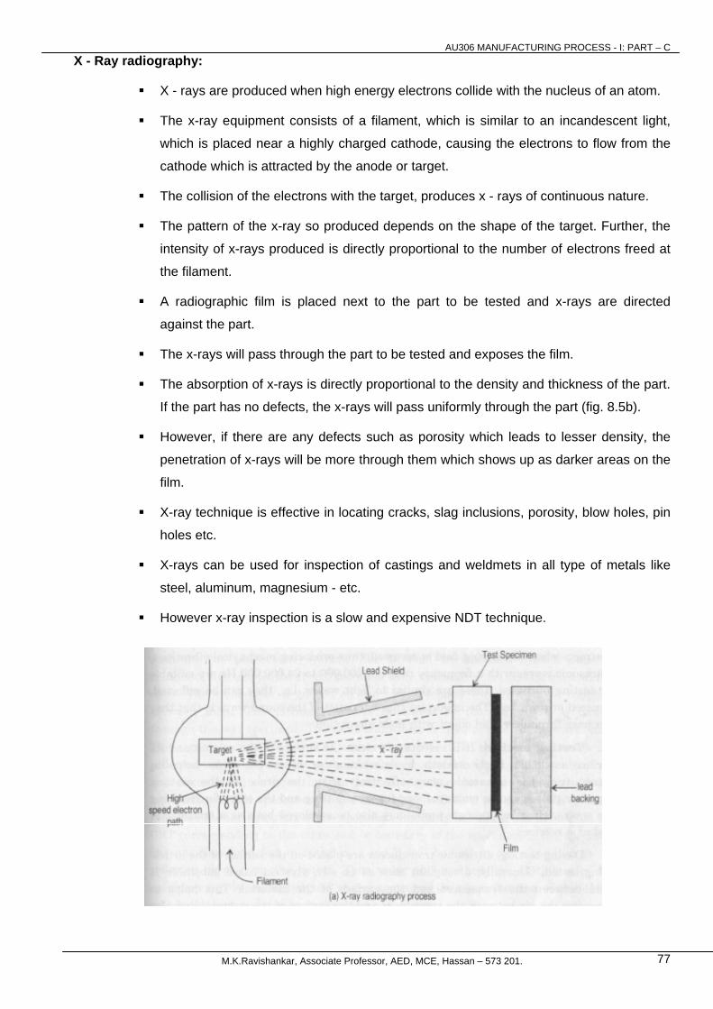
X - Ray radiography:
X - rays are produced when high energy electrons collide with the nucleus of an atom.
The x-ray equipment consists of a filament, which is similar to an incandescent light,
which is placed near a highly charged cathode, causing the electrons to flow from the
cathode which is attracted by the anode or target.
The collision of the electrons with the target, produces x - rays of continuous nature.
The pattern of the x-ray so produced depends on the shape of the target. Further, the
intensity of x-rays produced is directly proportional to the number of electrons freed at
the filament.
A radiographic film is placed next to the part to be tested and x-rays are directed
against the part.
The x-rays will pass through the part to be tested and exposes the film.
The absorption of x-rays is directly proportional to the density and thickness of the part.
If the part has no defects, the x-rays will pass uniformly through the part (fig. 8.5b).
However, if there are any defects such as porosity which leads to lesser density, the
penetration of x-rays will be more through them which shows up as darker areas on the
film.
X-ray technique is effective in locating cracks, slag inclusions, porosity, blow holes, pin
holes etc.
X-rays can be used for inspection of castings and weldmets in all type of metals like
steel, aluminum, magnesium - etc.
However x-ray inspection is a slow and expensive NDT technique.

AU306 MANUFACTURING PROCESS - I: PART – C
M.K.Ravishankar, Associate Professor, AED, MCE, Hassan – 573 201. 78
Figure 8.5 X-ray radiography
Ultrasonic testing:
Principle of operation:
Ultrasonic testing is based piezoelectric effect which converts electrical energy to mechanical
energy thus generating ultrasonic waves.
Ultrasonic waves are generated when a high frequency alternating current of about a million
times per second is impressed across the faces of a piezoelectric material like quartz crystal.
The crystal expands in first half of the cycle and contracts when the electric field is reversed,
thus producing mechanical vibrations.
Ultrasonic waves with a frequency range of 200,000 to 24,000,000 Hz are suitable for testing
purposes.
These are similar to light waves, i.e., they can be reflected, focussed or refracted.
The important characteristics of the sound wave is that they can pass through a solid object
with little absorption.
Testing method:
It is essential to clean the surface of the casting and surface is made fairly smooth by
machining or otherwise.
This helps transmitting the ultrasonic wave effectively from the probe to the casting.
Separate probes can be employed; one for transmitting and the other for receiving the waves.
However a single probe may also be employed both as a transmitter and as a receiver.
During testing, ultrasonic transducers are placed on the surface of the article being tested.
Generally, a couplant such as an oily, glycerin based substance is used between the
transducer and the surface of the material.
This helps in removing the air between the transducer and the surface of the material and also
it provides a medium for the transfer of the sound vibrations.
AU306 MANUFACTURING PROCESS - I: PART – C
M.K.Ravishankar, Associate Professor, AED, MCE, Hassan – 573 201. 79
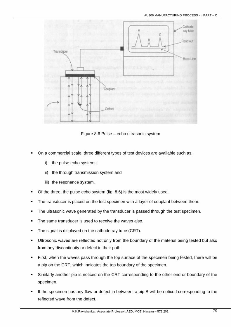
Figure 8.6 Pulse – echo ultrasonic system
On a commercial scale, three different types of test devices are available such as,
i) the pulse echo systems,
ii) the through transmission system and
iii) the resonance system.
Of the three, the pulse echo system (fig. 8.6) is the most widely used.
The transducer is placed on the test specimen with a layer of couplant between them.
The ultrasonic wave generated by the transducer is passed through the test specimen.
The same transducer is used to receive the waves also.
The signal is displayed on the cathode ray tube (CRT).
Ultrosonic waves are reflected not only from the boundary of the material being tested but also
from any discontinuity or defect in their path.
First, when the waves pass through the top surface of the specimen being tested, there will be
a pip on the CRT, which indicates the top boundary of the specimen.
Similarly another pip is noticed on the CRT corresponding to the other end or boundary of the
specimen.
If the specimen has any flaw or defect in between, a pip B will be noticed corresponding to the
reflected wave from the defect.
AU306 MANUFACTURING PROCESS - I: PART – C
M.K.Ravishankar, Associate Professor, AED, MCE, Hassan – 573 201. 80
Thus using this method, the thickness of the specimen can be measured and at the sametime
the exact location of the defect within the material can be easily determined.
Advantages
i) This method is quite fast and reliable.
ii) It is more sensitive than radiography.
iii) By using higher frequency ultrasonic waves, greater sensitivity can be achieved.
Disadvantages
i) This method is more sensitive to surface roughness and as a result surface machining is a
must.
ii) In intricate castings, the interpretation becomes difficult because the waves may also be
reflected by sharp corners etc.