Embed Size (px)
Citation preview
PART C:CHAPTER 5Construction
PART C Chapter 5ConstructionThis chapter provides information on the procedures for constructing concrete masonry structures.
Contents5.1 TYPES OF WALLS
5.2 CONSTRUCTING WALLS

PART C:CHAPTER 5Construction
5.1 TYPES OF WALLS
TYPES OF WALLS
Veneer walls (Figure 5.1c) are usually constructed as the outer walls of buildings and rely on a structural member of steel or timber to support the masonry veneer, to which it is tied by wall ties.
Cavity walls and diaphragm walls (Figure 5.1d,e,f,g) are generally constructed to serve as exterior walls where weather resistance is required, without resort to protective coatings. Such walls may be constructed of hollow or solid blocks, or standard or modular bricks. Both leaves may be built of the same type of unit, or one leaf may be hollow and one solid. One unit may be brick and one block, provided the heights of the units are such that at least every seventh bed joint of standard brickwork aligns with a bed joint of the blockwork. (Seven courses of standard height brickwork represent a height of 600 mm, ie the recommended cavity tie spacing.) Blocks 162 mm high with a 10-mm joint correspond to two standard brick courses (76 mm with a 10 mm joint). Blocks 119 mm high with a 10-mm joint correspond to one-and-a-half standard brick courses. The coincidence of course heights facilitates the installation of wall ties.
Single-leaf walls of hollow or solid blocks(Figure 5.1a,b) are used extensively as exterior and interior walls. If used externally, measures are needed to protect against weather penetration.
Reinforced and grouted hollow block walls (Figure 5.1b,e) are used as exterior and interior loadbearing walls in highly stressed situations, such as those encountered in multi-storey buildings of loadbearing wall construction and in structures subjected to high out-of-plane wind or earthquake loading. Unless such exterior walls form one leaf of a cavity wall, similar measures to those applied to unreinforced walls are required to resist weather penetration. Walls of this type are used frequently for retaining walls and as walls of swimming pools, water tanks and hydraulic structures. In such cases, special surface treatments will be needed, depending on the conditions of service.

PART C:CHAPTER 5Construction
(a) Unreinforced Single-leaf (b) Reinforced Single-leaf
SINGLE-LEAF WALLS
Solid or hollow concrete masonry
Vertical steelreinforcement(optional)
Vertical steelreinforcement (optional)
Horizontal steelreinforcementto bond beams(optional)
Bed-jointreinforcement(optional)
Hollow concrete blockwork
Inner leaf orouter leaf or both
may be reinforced
Inner leaf orouter leaf may
be solid or hollowconcrete masonry
Inner leaf orouter leaf may
be solid or hollowconcrete masonry
Inner leaf orouter leaf may
be solid or hollowconcrete masonry
(c) Unreinforced Veneer
VENEER WALLS
(d) Unreinforced Leaves (e) Reinforced Leaves
CAVITY WALLS
(g) Reinforced-cavity(f) Diaphragm
HYBRID WALLS
Solid or hollow concretemasonry outer leaf
Masonry-veneer ties
Structuralbacking
Open perpendsas weepholesfor drainageof cavity
Cavity ties
Flashing
Weepholes
Flashing
Outer leaf
Inner leaf
Horizontal steelreinforcement(optional)
Cavity ties
Flashing
Outer leaf
Inner leaf
Vertical steel reinforcementin mortar-filled cavity
Horizontal steelreinforcementin cavity
Cavity ties
Outer leaf
Inner leaf
Inner leaf
Headers bonded to theinternal and externalleaves with ties
Outer leaf
Figure 5.1 Masonry Wall Types
PART C:CHAPTER 5Construction
5.2 CONSTRUCTING WALLS
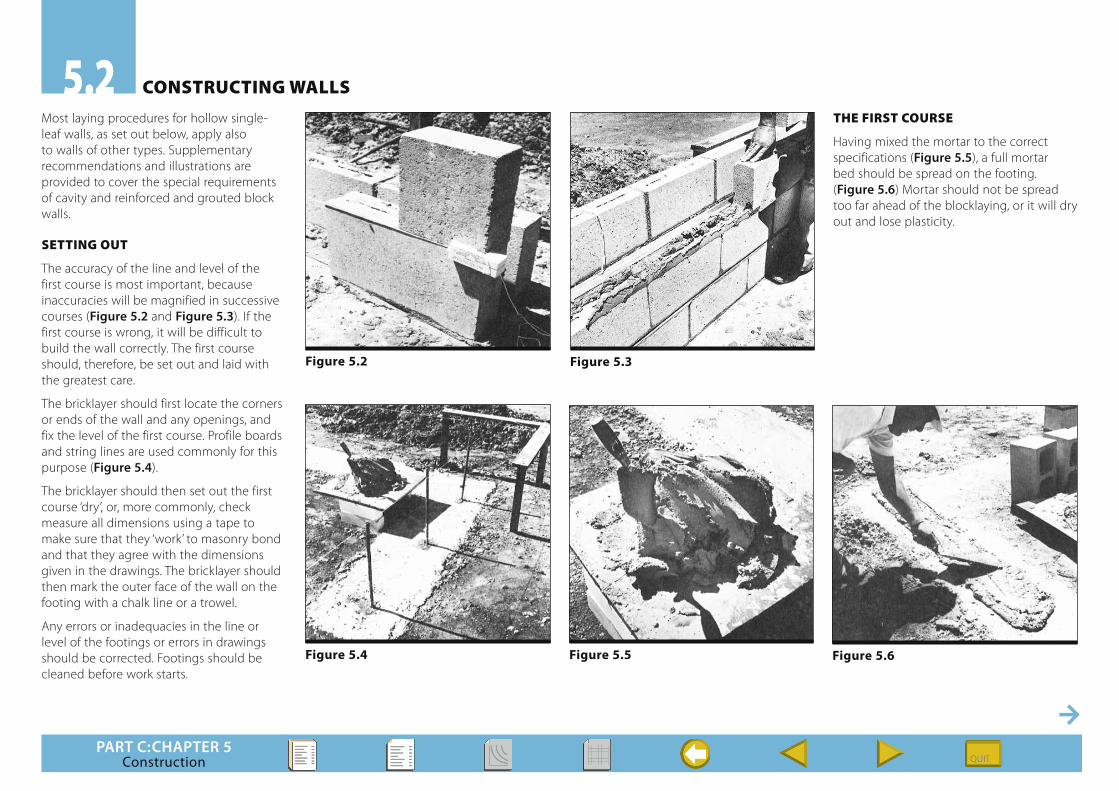
Most laying procedures for hollow single-leaf walls, as set out below, apply also to walls of other types. Supplementary recommendations and illustrations are provided to cover the special requirements of cavity and reinforced and grouted block walls.
SETTING OUT
The accuracy of the line and level of the first course is most important, because inaccuracies will be magnified in successive courses (Figure 5.2 and Figure 5.3). If the first course is wrong, it will be difficult to build the wall correctly. The first course should, therefore, be set out and laid with the greatest care.
The bricklayer should first locate the corners or ends of the wall and any openings, and fix the level of the first course. Profile boards and string lines are used commonly for this purpose (Figure 5.4).
The bricklayer should then set out the first course ‘dry’, or, more commonly, check measure all dimensions using a tape to make sure that they ‘work’ to masonry bond and that they agree with the dimensions given in the drawings. The bricklayer should then mark the outer face of the wall on the footing with a chalk line or a trowel.
Any errors or inadequacies in the line or level of the footings or errors in drawings should be corrected. Footings should be cleaned before work starts.
ThE FIRST COURSE
Having mixed the mortar to the correct specifications (Figure 5.5), a full mortar bed should be spread on the footing. (Figure 5.6) Mortar should not be spread too far ahead of the blocklaying, or it will dry out and lose plasticity.
Figure 5.2 Figure 5.3
Figure 5.4 Figure 5.6 Figure 5.5

PART C:CHAPTER 5Construction
The corner units should be laid first and positioned accurately (Figure 5.7). A string line is stretched between the corners at the level of the top of the first course (Figure 5.8).
Blocks should be laid with the widest parts of the shells and webs uppermost, as this facilitates the spreading of the mortar bed. Double-U blocks and H blocks are the correct blocks to use in retaining walls. If blocks with rebated webs are used with horizontal reinforcement, it will be necessary to lay alternate courses upside-down so that the rebates match, creating larger openings – holes through which the horizontal reinforcement passes.
Any adjustments to the position of blocks should be made while the mortar is plastic and before any more blocks are laid. Each unit is levelled and aligned to the string line by light tapping with the trowel or a hammer (Figures 5.9 and 5.10).
As each block is laid, excess mortar extruded from the joints should be cut off with the trowel and returned to the mortar board, to be reworked with the fresh mortar (Figure 5.11).
When laying hollow blocks, mortar should be applied only to the face shells and their vertical projections on the head joints (Figure 5.12). Unless specified otherwise, mortar is not applied to the cross webs or to full head joints. This procedure helps to isolate the faces of the wall from leakage paths through mortar joints, so reducing the tendency for capillary leakage caused
by weather. In fully grouted reinforced block walls, the unfilled sections of joints are filled
during grouting, providing an additional ‘key’ for the grout.
Figure 5.7 Figure 5.8 Figure 5.9
Figure 5.10 Figure 5.11 Figure 5.12
PART C:CHAPTER 5Construction
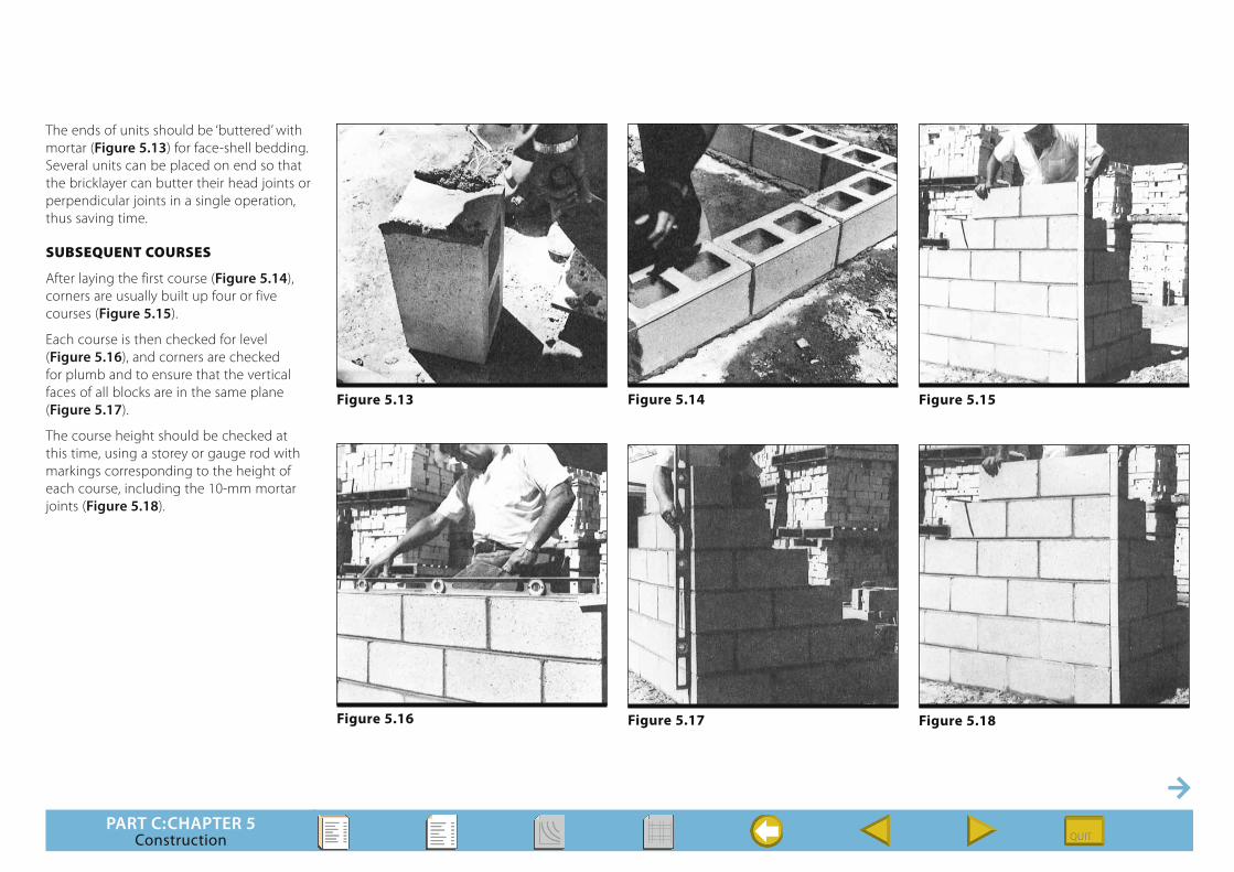
The ends of units should be ‘buttered’ with mortar (Figure 5.13) for face-shell bedding. Several units can be placed on end so that the bricklayer can butter their head joints or perpendicular joints in a single operation, thus saving time.
SUbSEqUENT COURSES
After laying the first course (Figure 5.14), corners are usually built up four or five courses (Figure 5.15).
Each course is then checked for level (Figure 5.16), and corners are checked for plumb and to ensure that the vertical faces of all blocks are in the same plane (Figure 5.17).
The course height should be checked at this time, using a storey or gauge rod with markings corresponding to the height of each course, including the 10-mm mortar joints (Figure 5.18).
Figure 5.13 Figure 5.14 Figure 5.15
Figure 5.16 Figure 5.17 Figure 5.18
PART C:CHAPTER 5Construction
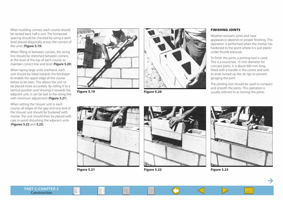
When building corners, each course should be racked back half a unit. The horizontal spacing should be checked by using a spirit level placed diagonally across the corners of the units (Figure 5.19).
When ‘filling in’ between corners, the string line should be stretched between corners, at the level of the top of each course, to maintain correct line and level (Figure 5.20).
When laying large units overhand, each unit should be tilted towards the bricklayer to enable the upper edge of the course below to be seen. This allows the unit to be placed more accurately. By rolling it to a vertical position and ‘shoving’ it towards the adjacent unit, it can be laid to the string line with minimum adjustment (Figure 5.21).
When setting the ‘closure’ unit in each course, all edges of the gap and one end of the ‘closure’ unit should be ‘buttered’ with mortar. The unit should then be placed with care to avoid disturbing the adjacent units (Figures 5.22 and 5.23).
FINIShING JOINTS
Weather-resistant joints and neat appearance depend on proper finishing. This operation is performed when the mortar has hardened to the point where it is just plastic under thumb pressure.
To finish the joints, a jointing tool is used. This is a round bar, 15 mm diameter for concave joints. It is about 600 mm long, fitted with a handle in the centre and with its ends turned up like ski tips to prevent gouging the joint.
The jointing tool should be used to compact and smooth the joints. This operation is usually referred to as ‘ironing’ the joints.
Figure 5.21 Figure 5.22 Figure 5.23
Figure 5.19 Figure 5.20

PART C:CHAPTER 5Construction
Vertical joints should be finished first (Figure 5.24) to avoid damaging finished horizontal joints (Figure 5.25). After finishing, surplus mortar is removed with the trowel (Figure 5.26). Any burrs may be removed after hardening by rubbing with a flat piece of block of the same colour as the wall (Figure 5.27).
Raking joints is not permitted in hollow blockwork since it leads to leakage due to the collection of rainwater in the water traps formed in raked joints. In loadbearing walls, the effective cross-section and load capacity of the wall are reduced by raking the joints.
CLEANING
Special care should be taken to prevent mortar smearing or dropping on the surface of the wall. Embedded mortar smears can not be removed completely after hardening, and show through most paints or surface treatments. Mortar droppings adhering to a wall should be allowed to dry before they are removed with a brush or a trowel. When dry and hard, most of the mortar remaining can be removed by rubbing with a small piece of concrete block the same colour as the wall (Figure 5.28). Many cleaning problems can be avoided, particularly with coloured blocks, by using coloured mortar that matches the wall. However, the best treatment is to keep the walls clean while they are being built.
Figure 5.24 Figure 5.25
Figure 5.26 Figure 5.27 Figure 5.28
PART C:CHAPTER 5Construction
SUPPLEmENTARY RECOmmENdATIONS
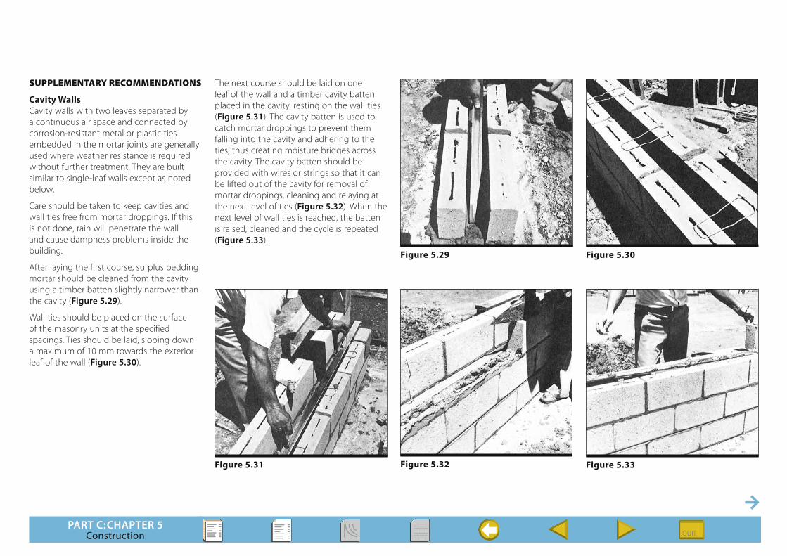
Cavity WallsCavity walls with two leaves separated by a continuous air space and connected by corrosion-resistant metal or plastic ties embedded in the mortar joints are generally used where weather resistance is required without further treatment. They are built similar to single-leaf walls except as noted below.
Care should be taken to keep cavities and wall ties free from mortar droppings. If this is not done, rain will penetrate the wall and cause dampness problems inside the building.
After laying the first course, surplus bedding mortar should be cleaned from the cavity using a timber batten slightly narrower than the cavity (Figure 5.29).
Wall ties should be placed on the surface of the masonry units at the specified spacings. Ties should be laid, sloping down a maximum of 10 mm towards the exterior leaf of the wall (Figure 5.30).
The next course should be laid on one leaf of the wall and a timber cavity batten placed in the cavity, resting on the wall ties (Figure 5.31). The cavity batten is used to catch mortar droppings to prevent them falling into the cavity and adhering to the ties, thus creating moisture bridges across the cavity. The cavity batten should be provided with wires or strings so that it can be lifted out of the cavity for removal of mortar droppings, cleaning and relaying at the next level of ties (Figure 5.32). When the next level of wall ties is reached, the batten is raised, cleaned and the cycle is repeated (Figure 5.33).
Figure 5.29 Figure 5.30
Figure 5.31 Figure 5.32 Figure 5.33

PART C:CHAPTER 5Construction
Another measure required to keep dampness from the interior leaves of cavity walls is the installation of cavity flashings and the provision of weep holes. Flashings are bent in a reverse sloping Z-shape, and placed so that the edges of the horizontal surfaces do not quite reach the outsides of the mortar joints. Where the cavity flashing is also to act as a damp-proof course, the flashing shall extend to the external face of the masonry and be visible. The high side of the flashing is laid on the interior leaf of the wall. Both horizontal surfaces of the flashing are laid on units before mortar is placed. The mortar beds should be then laid and the next courses placed above the flashing (Figure 5.34).
Alternate head joints in the exterior leaf immediately above the flashing course should be left free of mortar to form weep holes. Any rainwater that penetrates the outer leaf is collected by the flashing and drains through the weep holes to the outside of the wall.
Care must be taken to avoid mortar droppings on the flashing. Such droppings will block weep holes and retain water, thus causing a damp interior leaf. The use of cavity battens will avoid this problem.
Reinforced Concrete Block WallsReinforced concrete block walls consist of hollow blocks with vertical and horizontal reinforcement fully encased in grout.
Except for short starter bars cast in the concrete footing, the vertical reinforcing bars are usually placed in the hollow cores after the wall is completed. The horizontal bars are placed in U-shaped lintel blocks or in the rebated webs of double-U or H blocks progressively as the wall is built.
On completion of blocklaying and placing of reinforcement, the vertical and horizontal bars are encased completely in grout, placed by pouring or pumping from the top of the wall or from the level of a major change in wall thickness.
Blocklaying practice is much the same as for unreinforced concrete block walls, except as discussed and illustrated below.
The starter bars for the vertical reinforcement are cast in the footing at the specified spacing at the time the footing is placed. Short starter bars are used instead of full wall height bars, so that the blocks will not have to be lifted and threaded over vertical bars (Figure 5.35). Starter bars must be accurately supported from the timber formwork of the footing.
The first course consists of special blocks with cleaning holes (clean-out blocks). These are used to allow the cores to be cleaned of mortar and rubbish before grouting (Figure 5.36).
Subsequent courses should consist of H blocks or double-U blocks, which permit horizontal reinforcement to be completely encased by concrete grout (Figure 5.37).
Figure 5.34
Figure 5.35 Figure 5.36
H BLOCK
DOUBLE-U BLOCK
Figure 5.37

PART C:CHAPTER 5Construction
If flush-ended blocks are used, they must incorporate rebates in the webs, which permit sufficient clearance around the horizontal bars to enable them to be supported 20 mm clear of the webs. This may be assisted by turning blocks in alternate courses upside-down, thus increasing the clearance.
The construction of the wall continues as for an unreinforced wall except for the placement of horizontal reinforcement courses at specified intervals.
When the wall is completed to its full height, the mortar should be allowed to set and cure. The mortar fins that are extruded into the cores during the laying process, and which would interfere with the placing of grout, should be removed by rodding (Figure 5.38). The pieces of surplus mortar so dislodged are then removed from the clean-out holes (Figure 5.39).
The main vertical reinforcement should be placed and tied to the starter bars (Figure 5.40). It is secured at its upper end to prevent movement relative to the cores and to maintain it in the correct position.
The clean-out holes should then be closed to retain the grout. This can be done in several ways. Where appearance is not important, closure may be by means of covers which are either attached to the vertical reinforcing steel by hook bolts or are prevented from moving by propped and wedged timbers (Figures 5.41 and 5.42).
Figure 5.38 Figure 5.39
Figure 5.40 Figure 5.41 Figure 5.42

PART C:CHAPTER 5Construction
Where appearance is important, and both faces of the wall must maintain bond, the following procedure may be adopted. Instead of using special cleanout blocks for the first course, standard hollow blocks (X.01 type units) maybe used. One face shell and part of the webs on that side are removed by sawing to reduce the overall thickness of the blocks by approximately 50 mm. After cleaning the cores, the cleanout holes are blocked by using 390 mm x 190 mm x 40 mm thick (5031) units, laid to maintain bond (Figure 5.43). These units are bedded in mortar to the X.01 units. To prevent movement or damage, they should be restrained and supported by propping over their full length and height.
Grout should be of such consistency as to give free flow without segregation. The slump at the time of placing should be approximately 225 mm. Grout used to protect reinforcement should have a portland cement content of at least 300 kg/m3 and a characteristic strength greater than 12 MPa. A value of at least 20 MPa is recommended. The recommended maximum aggregate size is 10 mm, and should not exceed 20 mm (Figure 5.44).
The grout may be placed by hand (Figure 5.45) or by pumping (Figures 5.46 and 5.47). It should be rodded or mechanically vibrated during the placing process to complete the filling of the cores. Grout will usually settle in the cores a short time after placing. Cores should be topped up while the grout is still plastic and the additional grout rodded into the earlier material.
Core cleanout blocks(produced by sawing approx.50 mm off the face ofX.01 type units)
Closing units (50.31 units)laid to maintain bond
Figure 5.43 Figure 5.44
Figure 5.45 Figure 5.46 Figure 5.47
PART C:CHAPTER 5Construction
PROTECTION OF mATERIALS ANd WORk dURING CONSTRUCTION
Masonry units should be stored and protected on site in such a way as to prevent:
■ damage by chipping and breakage;
■ wetting by rain or ground water, or increase in moisture content from other causes;
■ contamination by mud, dust, atmospheric pollution or other substances likely to cause staining or loss of bond;
■ entry of salts in solution from ground or other sources; and
■ damage by frost.
Except for chipping and breakage, all of the above-mentioned damage may be prevented by stacking units on supports clear of the ground, and covering them with heavy polythene, tarpaulins or other suitable material in such a way that some circulation of air is maintained.
Mortar and mortar materials should also be stored on site so that they are protected from contamination and dampness. Pre-mixed mortar should be kept dry and free from premature deterioration.
IMPORTANT: Concrete masonry units should not be wetted before laying. The only exception to this rule is in extremely hot, dry conditions, when it may be permissible to sprinkle the bonding surfaces lightly with water immediately before laying, to reduce suction.
Completed and partly completed work should be protected by covering when necessary to prevent physical damage or surface contamination by rain or water and extreme heat or cold. Exposed tops of walls should be covered at the end of each day’s work, or immediately if rain begins during the day, to prevent entry of water.
Precautions should be taken to prevent masonry being subjected to loading until the mortar and or the grout have hardened sufficiently to support the load without damage.
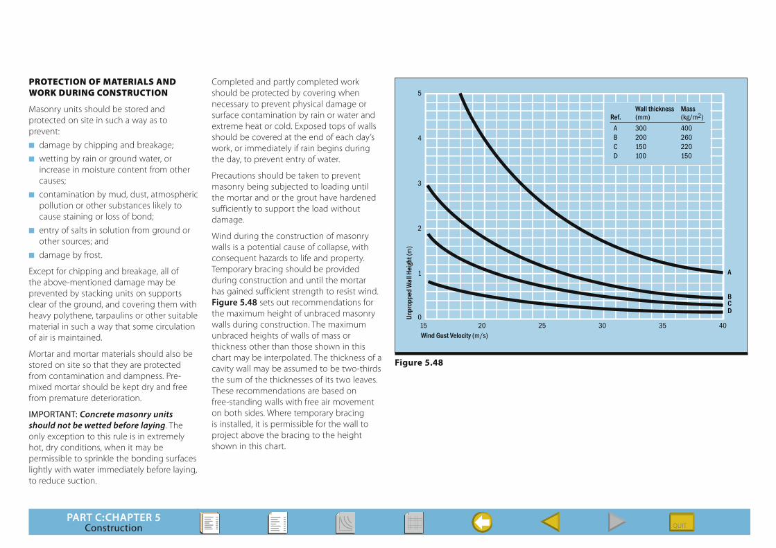
Wind during the construction of masonry walls is a potential cause of collapse, with consequent hazards to life and property. Temporary bracing should be provided during construction and until the mortar has gained sufficient strength to resist wind. Figure 5.48 sets out recommendations for the maximum height of unbraced masonry walls during construction. The maximum unbraced heights of walls of mass or thickness other than those shown in this chart may be interpolated. The thickness of a cavity wall may be assumed to be two-thirds the sum of the thicknesses of its two leaves. These recommendations are based on free-standing walls with free air movement on both sides. Where temporary bracing is installed, it is permissible for the wall to project above the bracing to the height shown in this chart.
15 20 25 30 35 40Wind Gust Velocity (m/s)
Wall thickness MassRef. (mm) (kg/m2)
A 300 400B 200 260C 150 220D 100 150
A
BCD
0
1
2
3
4
5
Unpr
oppe
d W
all H
eigh
t (m
)
Figure 5.48