Embed Size (px)
Citation preview

- 293 -
PART 6
Requirements for the construction and testing of packagings,
intermediate bulk containers (IBCs), large packagings, tanks and bulk containers
Copyright © United Nations, 2010. All rights reserved

Copyright © United Nations, 2010. All rights reserved

- 295 -
CHAPTER 6.1
REQUIREMENTS FOR THE CONSTRUCTION AND TESTING OF PACKAGINGS
6.1.1 General 6.1.1.1 The requirements of this Chapter do not apply to:
(a) Packages containing radioactive material of Class 7, unless otherwise provided (see 4.1.9);
(b) Packages containing infectious substances of Class 6.2, unless otherwise provided
(see Chapter 6.3, Note and packing instruction P621 of 4.1.4.1); (c) Pressure receptacles containing gases of Class 2; (d) Packages whose net mass exceeds 400 kg; (e) Packagings with a capacity exceeding 450 litres.
6.1.1.2 The requirements for packagings in 6.1.4 are based on packagings currently used. In order to
take into account progress in science and technology, there is no objection to the use of packagings having specifications different from those in 6.1.4, provided that they are equally effective, acceptable to the competent authority and able successfully to withstand the tests described in 6.1.1.3 and 6.1.5. Methods of testing other than those described in this Chapter are acceptable, provided they are equivalent, and are recognized by the competent authority.
6.1.1.3 Every packaging intended to contain liquids shall successfully undergo a suitable
leakproofness test, and be capable of meeting the appropriate test level indicated in 6.1.5.4.3:
(a) Before it is first used for carriage; (b) After remanufacturing or reconditioning, before it is re-used for carriage;
For this test, packagings need not have their own closures fitted. The inner receptacle of composite packagings may be tested without the outer packaging
provided the test results are not affected. This test is not necessary for:
- Inner packagings of combination packagings; - Inner receptacles of composite packagings (glass, porcelain or stoneware), marked
with the symbol "RID/ADR" according to 6.1.3.1 (a) (ii); - Light gauge metal packagings, marked with the symbol "RID/ADR" according to
6.1.3.1 (a) (ii). 6.1.1.4 Packagings shall be manufactured, reconditioned and tested under a quality assurance
programme which satisfies the competent authority in order to ensure that each packaging meets the requirements of this Chapter.
NOTE: ISO 16106:2006 "Packaging – Transport packages for dangerous goods –
Dangerous goods packagings, intermediate bulk containers (IBCs) and large packagings –
Copyright © United Nations, 2010. All rights reserved

- 296 -
Guidelines for the application of ISO 9001" provides acceptable guidance on procedures which may be followed.
6.1.1.5 Manufacturers and subsequent distributors of packagings shall provide information regarding procedures to be followed and a description of the types and dimensions of closures (including required gaskets) and any other components needed to ensure that packages as presented for carriage are capable of passing the applicable performance tests of this Chapter.
6.1.2 Code for designating types of packagings 6.1.2.1 The code consists of:
(a) An Arabic numeral indicating the kind of packaging, e.g. drum, jerrican, etc., followed by;
(b) A capital letter(s) in Latin characters indicating the nature of the material, e.g. steel, wood, etc., followed where necessary by;
(c) An Arabic numeral indicating the category of packaging within the kind to which the packaging belongs.
6.1.2.2 In the case of composite packagings, two capital letters in Latin characters are used in
sequence in the second position of the code. The first indicates the material of the inner receptacle and the second that of the outer packaging.
6.1.2.3 In the case of combination packagings only the code number for the outer packaging is used. 6.1.2.4 The letters "T", "V" or "W" may follow the packaging code. The letter "T" signifies a
salvage packaging conforming to the requirements of 6.1.5.1.11. The letter "V" signifies a special packaging conforming to the requirements of 6.1.5.1.7. The letter "W" signifies that the packaging, although of the same type indicated by the code, is manufactured to a specification different to that in 6.1.4 and is considered equivalent under the requirements of 6.1.1.2.
6.1.2.5 The following numerals shall be used for the kinds of packaging: l. Drum 2. (Reserved) 3. Jerrican 4. Box 5. Bag 6. Composite packaging 7. (Reserved) 0. Light gauge metal packagings 6.1.2.6 The following capital letters shall be used for the types of material: A. Steel (all types and surface treatments) B. Aluminium C. Natural wood D. Plywood F. Reconstituted wood G. Fibreboard H. Plastics material L. Textile M. Paper, multiwall N. Metal (other than steel or aluminium)
Copyright © United Nations, 2010. All rights reserved

- 297 -
P. Glass, porcelain or stoneware
NOTE: Plastics material is taken to include other polymeric materials such as rubber.
6.1.2.7 The following table indicates the codes to be used for designating types of packagings depending on the kind of packagings, the material used for their construction and their category; it also refers to the sub-sections to be consulted for the appropriate requirements:
Kind Material Category Code Sub-section
non-removable head 1A1 A. Steel removable head 1A2
6.1.4.1
non-removable head 1B1 B. Aluminium removable head 1B2
6.1.4.2
D. Plywood 1D 6.1.4.5 G. Fibre 1G 6.1.4.7
non-removable head 1H1 H. Plastics removable head 1H2
6.1.4.8
non-removable head 1N1
1. Drums
N. Metal, other than steel or aluminium removable head 1N2
6.1.4.3
2. (Reserved) non-removable head 3A1 A. Steel removable head 3A2
6.1.4.4
non-removable head 3B1 B. Aluminium removable head 3B2
6.1.4.4
non-removable head 3H1
3. Jerricans
H. Plastics removable head 3H2
6.1.4.8
A. Steel 4A 6.1.4.14 B. Aluminium 4B 6.1.4.14
ordinary 4C1 C. Natural wood with sift-proof walls 4C2
6.1.4.9
D. Plywood 4D 6.1.4.10 F. Reconstituted wood 4F 6.1.4.11 G. Fibreboard 4G 6.1.4.12
expanded 4H1
4. Boxes
H. Plastics solid 4H2
6.1.4.13
5. Bags H. Woven plastics without inner liner or coating
5H1
sift-proof 5H2 water resistant 5H3
6.1.4.16
H. Plastics film 5H4 6.1.4.17 L. Textile without inner liner or
coating 5L1
sift-proof 5L2 water resistant 5L3
6.1.4.15
M. Paper multiwall 5M1 multiwall, water resistant 5M2
6.1.4.18
Copyright © United Nations, 2010. All rights reserved

- 298 -
Kind Material Category Code Sub-section with outer steel drum 6HA1 with outer steel crate or box 6HA2 with outer aluminium drum 6HB1 with outer aluminium crate or box
6HB2
with outer wooden box 6HC with outer plywood drum 6HD1 with outer plywood box 6HD2 with outer fibre drum 6HG1 with outer fibreboard box 6HG2 with outer plastics drum 6HH1
H. Plastics receptacle
with outer solid plastics box
6HH2
6.1.4.19
with outer steel drum 6PA1 with outer steel crate or box 6PA2 with outer aluminium drum 6PB1 with outer aluminium crate or box
6PB2
with outer wooden box 6PC with outer plywood drum 6PD1 with outer wickerwork hamper
6PD2
with outer fibre drum 6PG1 with outer fibreboard box 6PG2 with outer expanded plastics packaging
6PH1
6. Composite packagings
P. Glass, porcelain or stoneware receptacle
with outer solid plastics packaging
6PH2
6.1.4.20
7. (Reserved) non-removable head 0A1 0. Light gauge metal
packagings A. Steel
removable head 0A2 6.1.4.22
6.1.3 Marking NOTE 1: The marking indicates that the packaging which bears it corresponds to a
successfully tested design type and that it complies with the requirements of this Chapter which are related to the manufacture, but not to the use, of the packaging. In itself, therefore, the mark does not necessarily confirm that the packaging may be used for any substance: generally the type of packaging (e.g. steel drum), its maximum capacity and/or mass, and any special requirements are specified for each substance in Table A of Chapter 3.2.
NOTE 2: The marking is intended to be of assistance to packaging manufacturers,
reconditioners, packaging users, carriers and regulatory authorities. In relation to the use of a new packaging, the original marking is a means for its manufacturer(s) to identify the type and to indicate those performance test regulations that have been met.
NOTE 3: The marking does not always provide full details of the test levels, etc., and these
may need to be taken further into account, e.g. by reference to a test certificate, to test
Copyright © United Nations, 2010. All rights reserved

- 299 -
reports or to a register of successfully tested packagings. For example, a packaging having an X or Y marking may be used for substances to which a packing group having a lesser degree of danger has been assigned with the relevant maximum permissible value of the relative density 1 determined by taking into account the factor 1.5 or 2.25 indicated in the packaging test requirements in 6.1.5 as appropriate, i.e. packing group I packaging tested for products of relative density 1.2 could be used as a packing group II packaging for products of relative density 1.8 or a packing group III packaging for products of relative density 2.7, provided of course that all the performance criteria can still be met with the higher relative density product.
6.1.3.1 Each packaging intended for use according to the ADR shall bear markings which are
durable, legible and placed in a location and of such a size relative to the packaging as to be readily visible. For packages with a gross mass of more than 30 kg, the markings or a duplicate thereof shall appear on the top or on a side of the packaging. Letters, numerals and symbols shall be at least 12 mm high, except for packagings of 30 litres or 30 kg capacity or less, when they shall be at least 6 mm in height and for packagings of 5 litres or 5 kg or less when they shall be of an appropriate size.
The marking shall show:
(a) (i) The United Nations packaging symbol
;
This symbol shall not be used for any purpose other than certifying that a packaging, a portable tank or a MEGC complies with the relevant requirements in Chapter 6.1, 6.2, 6.3, 6.5, 6.6 or 6.7. This symbol shall not be used for packagings which comply with the simplified conditions of 6.1.1.3, 6.1.5.3.1 (e), 6.1.5.3.5 (c), 6.1.5.4, 6.1.5.5.1 and 6.1.5.6 (see also (ii) below). For embossed metal packagings, the capital letters "UN" may be applied instead of the symbol; or
(ii) The symbol "RID/ADR" for composite packagings (glass, porcelain or
stoneware) and light gauge metal packagings conforming to simplified conditions (see 6.1.1.3, 6.1.5.3.1 (e), 6.1.5.3.5 (c), 6.1.5.4, 6.1.5.5.1 and 6.1.5.6);
NOTE: Packagings bearing this symbol are approved for rail, road and inland waterways transport operations which are subject to the provisions of RID, ADR and ADN respectively. They are not necessarily accepted for carriage by other modes of transport or for transport operations by road, rail or inland waterways which are governed by other regulations.
(b) The code designating the type of packaging according to 6.1.2; (c) A code in two parts:
(i) a letter designating the packing group(s) for which the design type has been successfully tested:
X for packing groups I, II and III; Y for packing groups II and III; Z for packing group III only;
1 Relative density (d) is considered to be synonymous with Specific Gravity (SG) and is used throughout this text.
Copyright © United Nations, 2010. All rights reserved

- 300 -
(ii) the relative density, rounded off to the first decimal, for which the design type has been tested for packagings without inner packagings intended to contain liquids; this may be omitted when the relative density does not exceed 1.2. For packagings intended to contain solids or inner packagings, the maximum gross mass in kilograms.
For light-gauge metal packagings, marked with the symbol "RID/ADR" according to 6.1.3.1 (a) (ii) intended to contain liquids having a viscosity at 23 °C exceeding 200 mm2/s, the maximum gross mass in kg;
(d) Either the letter "S" denoting that the packaging is intended for the carriage of solids or inner packagings or, for packagings (other than combination packagings) intended to contain liquids, the hydraulic test pressure which the packaging was shown to withstand in kPa rounded down to the nearest 10 kPa.
For light-gauge metal packagings, marked with the symbol "RID/ADR, according to 6.1.3.1(a) (ii) intended to contain liquids having a viscosity at 23 °C exceeding 200 mm2/s, the letter "S";
(e) The last two digits of the year during which the packaging was manufactured. Packagings of types 1H and 3H shall also be appropriately marked with the month of manufacture; this may be marked on the packaging in a different place from the remainder of the marking. An appropriate method is:
(f) The State authorizing the allocation of the mark, indicated by the distinguishing sign
for motor vehicles in international traffic 2; (g) The name of the manufacturer or other identification of the packaging specified by the
competent authority.
6.1.3.2 In addition to the durable markings prescribed in 6.1.3.1, every new metal drum of a capacity greater than 100 litres shall bear the marks described in 6.1.3.1 (a) to (e) on the bottom, with an indication of the nominal thickness of at least the metal used in the body (in mm, to 0.1 mm), in permanent form (e.g. embossed). When the nominal thickness of either head of a metal drum is thinner than that of the body, the nominal thickness of the top head, body, and bottom head shall be marked on the bottom in permanent form (e.g. embossed), for example "1.0-1.2-1.0" or "0.9-1.0-1.0". Nominal thickness of metal shall be determined according to the appropriate ISO standard, for example ISO 3574:1999 for steel. The marks indicated in 6.1.3.1 (f) and (g) shall not be applied in a permanent form except as provided in 6.1.3.5.
2 Distinguishing sign for motor vehicles in international traffic prescribed in the Vienna Convention on Road Traffic (1968).
12
6
39
12
45
8
1011
7
Copyright © United Nations, 2010. All rights reserved

- 301 -
6.1.3.3 Every packaging other than those referred to in 6.1.3.2 liable to undergo a reconditioning process shall bear the marks indicated in 6.1.3.1 (a) to (e) in a permanent form. Marks are permanent if they are able to withstand the reconditioning process (e.g. embossed). For packagings other than metal drums of a capacity greater than 100 litres, these permanent marks may replace the corresponding durable markings prescribed in 6.1.3.1.
6.1.3.4 For remanufactured metal drums, if there is no change to the packaging type and no
replacement or removal of integral structural components, the required markings need not be permanent. Every other remanufactured metal drum shall bear the markings in 6.1.3.1 (a) to (e) in a permanent form (e.g. embossed) on the top head or side.
6.1.3.5 Metal drums made from materials (e.g. stainless steel) designed to be reused repeatedly may
bear the markings indicated in 6.1.3.1 (f) and (g) in a permanent form (e.g. embossed). 6.1.3.6 The marking in accordance with 6.1.3.1 is valid for only one design type or series of design
types. Different surface treatments may fall within the same design type. A "series of design types" means packagings of the same structural design, wall thickness,
material and cross-section, which differ only in their lesser design heights from the design type approved.
The closures of receptacles shall be identifiable as those referred to in the test report. 6.1.3.7 Marking shall be applied in the sequence of the sub-paragraphs in 6.1.3.1; each element of
the marking required in these sub-paragraphs and when appropriate sub-paragraphs (h) to (j) of 6.1.3.8 shall be clearly separated, e.g. by a slash or space, so as to be easily identifiable. For examples, see 6.1.3.11.
Any additional markings authorized by a competent authority shall still enable the parts of
the mark to be correctly identified with reference to 6.1.3.1. 6.1.3.8 After reconditioning a packaging, the reconditioner shall apply to it a durable marking
showing, in the following sequence:
(h) The State in which the reconditioning was carried out, indicated by the distinguishing sign for motor vehicles in international traffic 2;
(i) The name of the reconditioner or other identification of the packaging specified by the
competent authority; (j) The year of reconditioning; the letter "R"; and, for every packaging successfully
passing the leakproofness test in 6.1.1.3, the additional letter "L".
6.1.3.9 When, after reconditioning, the markings required by 6.1.3.1 (a) to (d) no longer appear on the top head or the side of a metal drum, the reconditioner also shall apply them in a durable form followed by 6.1.3.8 (h), (i) and (j). These markings shall not identify a greater performance capability than that for which the original design type had been tested and marked.
6.1.3.10 Packagings manufactured with recycled plastics material as defined in 1.2.1 shall be marked
"REC". This mark shall be placed near the mark prescribed in 6.1.3.1.
2 Distinguishing sign for motor vehicles in international traffic prescribed in the Vienna Convention on Road Traffic (1968).
Copyright © United Nations, 2010. All rights reserved

- 302 -
6.1.3.11 Examples of markings for NEW packagings
4G/Y145/S/02 NL/VL823
as in 6.1.3.1 (a) (i), (b), (c), (d) and (e) as in 6.1.3.1 (f) and (g) For a new fibreboard box
1A1/Y1.4/150/98 NL/VL824
as in 6.1.3.1 (a) (i), (b), (c), (d) and (e) as in 6.1.3.1 (f) and (g)
For a new steel drum to contain liquids
1A2/Y150/S/01 NL/VL825
as in 6.1.3.1 (a) (i), (b), (c), (d) and (e) as in 6.1.3.1 (f) and (g)
For a new steel drum to contain solids, or inner packagings
4HW/Y136/S/98 NL/VL826
as in 6.1.3.1 (a) (i), (b), (c), (d) and (e) as in 6.1.3.1 (f) and (g)
For a new plastics box of equivalent specification
1A2/Y/100/01 USA/MM5
as in 6.1.3.1 (a) (i), (b), (c), (d) and (e) as in 6.1.3.1 (f) and (g)
For a remanufactured steel drum to contain liquids
RID/ADR/0A1/Y100/89 NL/VL123
as in 6.1.3.1 (a) (ii), (b), (c), (d) and (e) as in 6.1.3.1 (f) and (g)
For a new light gauge metal packaging, non-removable head
RID/ADR/0A2/Y20/S/04 NL/VL124
as in 6.1.3.1 (a) (ii), (b), (c), (d) and (e) as in 6.1.3.1 (f) and (g)
For a new light gauge metal packaging, removable head, intended to contain solids, or liquids with a viscosity at 23 °C exceeding 200 mm2/s.
6.1.3.12 Examples of markings for RECONDITIONED packagings
1A1/Y1.4/150/97 NL/RB/01 RL
as in 6.1.3.1 (a) (i), (b), (c), (d) and (e) as in 6.1.3.8 (h), (i) and (j)
1A2/Y150/S/99 USA/RB/00 R
as in 6.1.3.1 (a) (i), (b), (c), (d) and (e) as in 6.1.3.8 (h), (i) and (j)
6.1.3.13 Example of marking for SALVAGE packagings
1A2T/Y300/S/01 USA/abc
as in 6.1.3.1 (a) (i), (b), (c), (d) and (e) as in 6.1.3.1 (f) and (g)
NOTE: The markings, for which examples are given in 6.1.3.11, 6.1.3.12 and 6.1.3.13 may be applied in a single line or in multiple lines provided the correct sequence is respected.
6.1.3.14 Certification By affixing marking in accordance with 6.1.3.1, it is certified that mass-produced packagings
correspond to the approved design type and that the requirements referred to in the approval have been met.
6.1.4 Requirements for packagings 6.1.4.0 General requirements Any permeation of the substance contained in the packaging shall not constitute a danger
under normal conditions of carriage.
Copyright © United Nations, 2010. All rights reserved

- 303 -
6.1.4.1 Steel drums 1A1 non-removable head 1A2 removable head 6.1.4.1.1 Body and heads shall be constructed of steel sheet of a suitable type and of adequate
thickness in relation to the capacity of the drum and to its intended use.
NOTE: In the case of carbon steel drums, "suitable" steels are identified in ISO 3573:1999 "Hot rolled carbon steel sheet of commercial and drawing qualities" and ISO 3574:1999 "Cold-reduced carbon steel sheet of commercial and drawing qualities". For carbon steel drums below 100 litres "suitable" steels in addition to the above standards are also identified in ISO 11949:1995 "Cold-reduced electrolytic tinplate", ISO 11950:1995 "Cold-reduced electrolytic chromium/chromium oxide-coated steel" and ISO 11951:1995 "Cold-reduced blackplate in coil form for the production of tinplate or electrolytic chromium/chromium-oxide coated steel".
6.1.4.1.2 Body seams shall be welded on drums intended to contain more than 40 litres of liquid.
Body seams shall be mechanically seamed or welded on drums intended to contain solids or 40 litres or less of liquids.
6.1.4.1.3 Chimes shall be mechanically seamed or welded. Separate reinforcing rings may be applied. 6.1.4.1.4 The body of a drum of a capacity greater than 60 litres shall, in general, have at least two
expanded rolling hoops or, alternatively, at least two separate rolling hoops. If there are separate rolling hoops they shall be fitted tightly on the body and so secured that they cannot shift. Rolling hoops shall not be spot welded.
6.1.4.1.5 Openings for filling, emptying and venting in the bodies or heads of non-removable head
(1A1) drums shall not exceed 7 cm in diameter. Drums with larger openings are considered to be of the removable head type (1A2). Closures for openings in the bodies and heads of drums shall be so designed and applied that they will remain secure and leakproof under normal conditions of carriage. Closure flanges may be mechanically seamed or welded in place. Gaskets or other sealing elements shall be used with closures, unless the closure is inherently leakproof.
6.1.4.1.6 Closure devices for removable head (1A2) drums shall be so designed and applied that they
will remain secure and drums will remain leakproof under normal conditions of carriage. Gaskets or other sealing elements shall be used with all removable heads.
6.1.4.1.7 If materials used for body, heads, closures and fittings are not in themselves compatible with
the contents to be carried, suitable internal protective coatings or treatments shall be applied. These coatings or treatments shall retain their protective properties under normal conditions of carriage.
6.1.4.1.8 Maximum capacity of drum: 450 litres. 6.1.4.1.9 Maximum net mass: 400 kg.
6.1.4.2 Aluminium drums 1B1 non-removable head 1B2 removable head 6.1.4.2.1 Body and heads shall be constructed of aluminium at least 99% pure or of an aluminium
base alloy. Material shall be of a suitable type and of adequate thickness in relation to the capacity of the drum and to its intended use.
Copyright © United Nations, 2010. All rights reserved

- 304 -
6.1.4.2.2 All seams shall be welded. Chime seams, if any, shall be reinforced by the application of separate reinforcing rings.
6.1.4.2.3 The body of a drum of a capacity greater than 60 litres shall, in general, have at least two
expanded rolling hoops or, alternatively, at least two separate rolling hoops. If there are separate rolling hoops they shall be fitted tightly on the body and so secured that they cannot shift. Rolling hoops shall not be spot welded.
6.1.4.2.4 Openings for filling, emptying and venting in the bodies or heads of non-removable head
(1B1) drums shall not exceed 7 cm in diameter. Drums with larger openings are considered to be of the removable head type (1B2). Closures for openings in the bodies and heads of drums shall be so designed and applied that they will remain secure and leakproof under normal conditions of carriage. Closure flanges shall be welded in place so that the weld provides a leakproof seam. Gaskets or other sealing elements shall be used with closures, unless the closure is inherently leakproof.
6.1.4.2.5 Closure devices for removable head (1B2) drums shall be so designed and applied that they
will remain secure and drums will remain leakproof under normal conditions of carriage. Gaskets or other sealing elements shall be used with all removable heads.
6.1.4.2.6 Maximum capacity of drum: 450 litres. 6.1.4.2.7 Maximum net mass: 400 kg. 6.1.4.3 Drums of metal other than aluminium or steel 1N1 non-removable head
1N2 removable head 6.1.4.3.1 The body and heads shall be constructed of a metal or of a metal alloy other than steel or
aluminium. Material shall be of a suitable type and of adequate thickness in relation to the capacity of the drum and to its intended use.
6.1.4.3.2 Chime seams, if any, shall be reinforced by the application of separate reinforcing rings. All
seams, if any, shall be joined (welded, solded, etc.) in accordance with the technical state of the art for the used metal or metal alloy.
6.1.4.3.3 The body of a drum of a capacity greater than 60 litres shall, in general, have at least two
expanded rolling hoops or, alternatively, at least two separate rolling hoops. If there are separate rolling hoops they shall be fitted tightly on the body and so secured that they cannot shift. Rolling hoops shall not be spot welded.
6.1.4.3.4 Openings for filling, emptying and venting in the bodies or heads of non-removable head
(1N1) drums shall not exceed 7 cm in diameter. Drums with larger openings are considered to be of the removable head type (1N2). Closures for openings in the bodies and heads of drums shall be so designed and applied that they will remain secure and leakproof under normal conditions of carriage. Closure flanges shall be joined in place (welded, solded, etc.) in accordance with the technical state of the art for the used metal or metal alloy so that the seam join is leakproof. Gaskets or other sealing elements shall be used with closures, unless the closure is inherently leakproof.
6.1.4.3.5 Closure devices for removable head (1N2) drums shall be so designed and applied that they
will remain secure and drums will remain leakproof under normal conditions of carriage. Gaskets or other sealing elements shall be used with all removable heads.
Copyright © United Nations, 2010. All rights reserved

- 305 -
6.1.4.3.6 Maximum capacity of drum: 450 litres. 6.1.4.3.7 Maximum net mass: 400 kg. 6.1.4.4 Steel or aluminium jerricans 3A1 steel, non-removable head 3A2 steel, removable head 3B1 aluminium, non-removable head 3B2 aluminium, removable head 6.1.4.4.1 Body and heads shall be constructed of steel sheet, of aluminium at least 99% pure or of an
aluminium base alloy. Material shall be of a suitable type and of adequate thickness in relation to the capacity of the jerrican and to its intended use.
6.1.4.4.2 Chimes of steel jerricans shall be mechanically seamed or welded. Body seams of steel
jerricans intended to contain more than 40 litres of liquid shall be welded. Body seams of steel jerricans intended to contain 40 litres or less shall be mechanically seamed or welded. For aluminium jerricans, all seams shall be welded. Chime seams, if any, shall be reinforced by the application of a separate reinforcing ring.
6.1.4.4.3 Openings in non-removable head jerricans (3A1 and 3B1) shall not exceed 7 cm in diameter.
Jerricans with larger openings are considered to be of the removable head type (3A2 and 3B2). Closures shall be so designed that they will remain secure and leakproof under normal conditions of carriage. Gaskets or other sealing elements shall be used with closures, unless the closure is inherently leakproof.
6.1.4.4.4 If materials used for body, heads, closures and fittings are not in themselves compatible with
the contents to be carried, suitable internal protective coatings or treatments shall be applied. These coatings or treatments shall retain their protective properties under normal conditions of carriage.
6.1.4.4.5 Maximum capacity of jerrican: 60 litres. 6.1.4.4.6 Maximum net mass: 120 kg. 6.1.4.5 Plywood drums 1D 6.1.4.5.1 The wood used shall be well seasoned, commercially dry and free from any defect likely to
lessen the effectiveness of the drum for the purpose intended. If a material other than plywood is used for the manufacture of the heads, it shall be of a quality equivalent to the plywood.
6.1.4.5.2 At least two-ply plywood shall be used for the body and at least three-ply plywood for the
heads; the plies shall be firmly glued together by a water resistant adhesive with their grain crosswise.
6.1.4.5.3 The body and heads of the drum and their joins shall be of a design appropriate to the capacity of the drum and to its intended use.
6.1.4.5.4 In order to prevent sifting of the contents, lids shall be lined with kraft paper or some other
equivalent material which shall be securely fastened to the lid and extend to the outside along its full circumference.
Copyright © United Nations, 2010. All rights reserved

- 306 -
6.1.4.5.5 Maximum capacity of drum: 250 litres. 6.1.4.5.6 Maximum net mass: 400 kg. 6.1.4.6 (Deleted) 6.1.4.7 Fibre drums 1G 6.1.4.7.1 The body of the drum shall consist of multiple plies of heavy paper or fibreboard (without
corrugations) firmly glued or laminated together and may include one or more protective layers of bitumen, waxed kraft paper, metal foil, plastics material, etc.
6.1.4.7.2 Heads shall be of natural wood, fibreboard, metal, plywood, plastics or other suitable
material and may include one or more protective layers of bitumen, waxed kraft paper, metal foil, plastics material, etc.
6.1.4.7.3 The body and heads of the drum and their joins shall be of a design appropriate to the
capacity of the drum and to its intended use. 6.1.4.7.4 The assembled packaging shall be sufficiently water resistant so as not to delaminate under
normal conditions of carriage. 6.1.4.7.5 Maximum capacity of drum: 450 litres. 6.1.4.7.6 Maximum net mass: 400 kg. 6.1.4.8 Plastics drums and jerricans 1H1 drums, non-removable head 1H2 drums, removable head 3H1 jerricans, non-removable head 3H2 jerricans, removable head 6.1.4.8.1 The packaging shall be manufactured from suitable plastics material and be of adequate
strength in relation to its capacity and intended use. Except for recycled plastics material as defined in 1.2.1, no used material other than production residues or regrind from the same manufacturing process may be used. The packaging shall be adequately resistant to ageing and to degradation caused either by the substance contained or by ultra-violet radiation. Any permeation of the substance contained in the package, or recycled plastics material used to produce new packaging, shall not constitute a danger under normal conditions of carriage.
6.1.4.8.2 If protection against ultra-violet radiation is required, it shall be provided by the addition of
carbon black or other suitable pigments or inhibitors. These additives shall be compatible with the contents and remain effective throughout the life of the packaging. Where use is made of carbon black, pigments or inhibitors other than those used in the manufacture of the tested design type, retesting may be waived if the carbon black content does not exceed 2% by mass or if the pigment content does not exceed 3% by mass; the content of inhibitors of ultra-violet radiation is not limited.
6.1.4.8.3 Additives serving purposes other than protection against ultra-violet radiation may be
included in the composition of the plastics material provided that they do not adversely affect the chemical and physical properties of the material of the packaging. In such circumstances, retesting may be waived.
Copyright © United Nations, 2010. All rights reserved

- 307 -
6.1.4.8.4 The wall thickness at every point of the packaging shall be appropriate to its capacity and intended use, taking into account the stresses to which each point is liable to be exposed.
6.1.4.8.5 Openings for filling, emptying and venting in the bodies or heads of non-removable head
drums (1H1) and jerricans (3H1) shall not exceed 7 cm in diameter. Drums and jerricans with larger openings are considered to be of the removable head type (1H2 and 3H2). Closures for openings in the bodies or heads of drums and jerricans shall be so designed and applied that they will remain secure and leakproof under normal conditions of carriage. Gaskets or other sealing elements shall be used with closures unless the closure is inherently leakproof.
6.1.4.8.6 Closure devices for removable head drums and jerricans (1H2 and 3H2) shall be so designed
and applied that they will remain secure and leakproof under normal conditions of carriage. Gaskets shall be used with all removable heads unless the drum or jerrican design is such that, where the removable head is properly secured, the drum or jerrican is inherently leakproof.
6.1.4.8.7 The maximum permissible permeability for flammable liquids shall be 0.008 g/l.h at 23 °C
(see 6.1.5.7). 6.1.4.8.8 Where recycled plastics material is used for production of new packaging, the specific
properties of the recycled material shall be assured and documented regularly as part of a quality assurance programme recognised by the competent authority. The quality assurance programme shall include a record of proper pre-sorting and verification that each batch of recycled plastics material has the proper melt flow rate, density, and tensile yield strength, consistent with that of the design type manufactured from such recycled material. This necessarily includes knowledge about the packaging material from which the recycled plastics have been derived, as well as the awareness of the prior contents of those packagings if those prior contents might reduce the capability of new packaging produced using that material. In addition, the packaging manufacturer's quality assurance programme under 6.1.1.4 shall include performance of the mechanical design type test in 6.1.5 on packagings manufactured from each batch of recycled plastics material. In this testing, stacking performance may be verified by appropriate dynamic compression testing rather than static load testing. NOTE: ISO 16103:2005 – "Packaging – Transport packaging for dangerous goods - Recycled plastics material" provides additional guidance on procedures to be followed in approving the use of recycled plastics material.
6.1.4.8.9 Maximum capacity of drums and jerricans: 1H1, 1H2: 450 litres 3H1, 3H2: 60 litres. 6.1.4.8.10 Maximum net mass: 1H1, 1H2: 400 kg 3H1, 3H2: 120 kg.
6.1.4.9 Boxes of natural wood 4C1 ordinary 4C2 with sift-proof walls 6.1.4.9.1 The wood used shall be well seasoned, commercially dry and free from defects that would
materially lessen the strength of any part of the box. The strength of the material used and the method of construction shall be appropriate to the capacity and intended use of the box. The tops and bottoms may be made of water resistant reconstituted wood such as hardboard, particle board or other suitable type.
Copyright © United Nations, 2010. All rights reserved
- 308 -
6.1.4.9.2 Fastenings shall be resistant to vibration experienced under normal conditions of carriage. End grain nailing shall be avoided whenever practicable. Joins which are likely to be highly stressed shall be made using clenched or annular ring nails or equivalent fastenings.
6.1.4.9.3 Box 4C2: each part shall consist of one piece or be equivalent thereto. Parts are considered
equivalent to one piece when one of the following methods of glued assembly is used: Lindermann joint, tongue and groove joint, ship lap or rabbet joint or butt joint with at least two corrugated metal fasteners at each joint.
6.1.4.9.4 Maximum net mass: 400 kg. 6.1.4.10 Plywood boxes 4D 6.1.4.10.1 Plywood used shall be at least 3-ply. It shall be made from well seasoned rotary cut, sliced or
sawn veneer, commercially dry and free from defects that would materially lessen the strength of the box. The strength of the material used and the method of construction shall be appropriate to the capacity and intended use of the box. All adjacent plies shall be glued with water resistant adhesive. Other suitable materials may be used together with plywood in the construction of boxes. Boxes shall be firmly nailed or secured to corner posts or ends or be assembled by equally suitable devices.
6.1.4.10.2 Maximum net mass: 400 kg. 6.1.4.11 Reconstituted wood boxes 4F 6.1.4.11.1 The walls of boxes shall be made of water resistant reconstituted wood such as hardboard,
particle board or other suitable type. The strength of the material used and the method of construction shall be appropriate to the capacity of the boxes and to their intended use.
6.1.4.11.2 Other parts of the boxes may be made of other suitable material. 6.1.4.11.3 Boxes shall be securely assembled by means of suitable devices. 6.1.4.11.4 Maximum net mass: 400 kg. 6.1.4.12 Fibreboard boxes 4G 6.1.4.12.1 Strong and good quality solid or double-faced corrugated fibreboard (single or multiwall)
shall be used, appropriate to the capacity of the box and to its intended use. The water resistance of the outer surface shall be such that the increase in mass, as determined in a test carried out over a period of 30 minutes by the Cobb method of determining water absorption, is not greater than 155 g/m2 - see ISO 535:l991. It shall have proper bending qualities. Fibreboard shall be cut, creased without scoring, and slotted so as to permit assembly without cracking, surface breaks or undue bending. The fluting of corrugated fibreboard shall be firmly glued to the facings.
6.1.4.12.2 The ends of boxes may have a wooden frame or be entirely of wood or other suitable
material. Reinforcements of wooden battens or other suitable material may be used.
Copyright © United Nations, 2010. All rights reserved

- 309 -
6.1.4.12.3 Manufacturing joins in the body of boxes shall be taped, lapped and glued, or lapped and stitched with metal staples. Lapped joins shall have an appropriate overlap.
6.1.4.12.4 Where closing is effected by gluing or taping, a water resistant adhesive shall be used. 6.1.4.12.5 Boxes shall be designed so as to provide a good fit to the contents. 6.1.4.12.6 Maximum net mass: 400 kg. 6.1.4.13 Plastics boxes 4H1 expanded plastics boxes 4H2 solid plastics boxes 6.1.4.13.1 The box shall be manufactured from suitable plastics material and be of adequate strength in
relation to its capacity and intended use. The box shall be adequately resistant to ageing and to degradation caused either by the substance contained or by ultra-violet radiation.
6.1.4.13.2 An expanded plastics box shall comprise two parts made of a moulded expanded plastics
material, a bottom section containing cavities for the inner packagings and a top section covering and interlocking with the bottom section. The top and bottom sections shall be designed so that the inner packagings fit snugly. The closure cap for any inner packaging shall not be in contact with the inside of the top section of this box.
6.1.4.13.3 For dispatch, an expanded plastics box shall be closed with a self-adhesive tape having
sufficient tensile strength to prevent the box from opening. The adhesive tape shall be weather resistant and its adhesive compatible with the expanded plastics material of the box. Other closing devices at least equally effective may be used.
6.1.4.13.4 For solid plastics boxes, protection against ultra-violet radiation, if required, shall be
provided by the addition of carbon black or other suitable pigments or inhibitors. These additives shall be compatible with the contents and remain effective throughout the life of the box. Where use is made of carbon black, pigments or inhibitors other than those used in the manufacture of the tested design type, retesting may be waived if the carbon black content does not exceed 2% by mass or if the pigment content does not exceed 3% by mass; the content of inhibitors of ultra-violet radiation is not limited.
6.1.4.13.5 Additives serving purposes other than protection against ultra-violet radiation may be
included in the composition of the plastics material provided that they do not adversely affect the chemical or physical properties of the material of the box. In such circumstances, retesting may be waived.
6.1.4.13.6 Solid plastics boxes shall have closure devices made of a suitable material of adequate
strength and so designed as to prevent the box from unintentional opening. 6.1.4.13.7 Where recycled plastics material is used for production of new packaging, the specific
properties of the recycled material shall be assured and documented regularly as part of a quality assurance programme recognised by the competent authority. The quality assurance programme shall include a record of proper pre-sorting and verification that each batch of recycled plastics material has the proper melt flow rate, density, and tensile yield strength, consistent with that of the design type manufactured from such recycled material. This necessarily includes knowledge about the packaging material from which the recycled plastics have been derived, as well as the awareness of the prior contents of those packagings if those prior contents might reduce the capability of new packaging produced using that material. In addition, the packaging manufacturer's quality assurance programme under 6.1.1.4 shall include performance of the mechanical design type test in 6.1.5 on packagings
Copyright © United Nations, 2010. All rights reserved

- 310 -
manufactured from each batch of recycled plastics material. In this testing, stacking performance may be verified by appropriate dynamic compression testing rather than static load testing.
6.1.4.13.8 Maximum net mass 4H1: 60 kg 4H2: 400 kg. 6.1.4.14 Steel or aluminium boxes 4A steel 4B aluminium 6.1.4.14.l The strength of the metal and the construction of the box shall be appropriate to the capacity
of the box and to its intended use. 6.1.4.14.2 Boxes shall be lined with fibreboard or felt packing pieces or shall have an inner liner or
coating of suitable material, as required. If a double seamed metal liner is used, steps shall be taken to prevent the ingress of substances, particularly explosives, into the recesses of the seams.
6.1.4.14.3 Closures may be of any suitable type; they shall remain secured under normal conditions of
carriage. 6.1.4.14.4 Maximum net mass: 400 kg.
6.1.4.15 Textile bags 5L1 without inner liner or coating 5L2 sift-proof 5L3 water resistant 6.1.4.15.1 The textiles used shall be of good quality. The strength of the fabric and the construction of
the bag shall be appropriate to the capacity of the bag and to its intended use. 6.1.4.15.2 Bags, sift-proof, 5L2: the bag shall be made sift-proof, for example by the use of:
(a) paper bonded to the inner surface of the bag by a water resistant adhesive such as bitumen; or
(b) plastics film bonded to the inner surface of the bag; or (c) one or more inner liners made of paper or plastics material.
6.1.4.15.3 Bags, water resistant, 5L3: to prevent the entry of moisture the bag shall be made
waterproof, for example by the use of: (a) separate inner liners of water resistant paper (e.g. waxed kraft paper, tarred paper or
plastics-coated kraft paper); or (b) plastics film bonded to the inner surface of the bag; or (c) one or more inner liners made of plastics material.
6.1.4.15.4 Maximum net mass: 50 kg.
Copyright © United Nations, 2010. All rights reserved

- 311 -
6.1.4.16 Woven plastics bags 5H1 without inner liner or coating 5H2 sift-proof 5H3 water resistant 6.1.4.16.1 Bags shall be made from stretched tapes or monofilaments of a suitable plastics material.
The strength of the material used and the construction of the bag shall be appropriate to the capacity of the bag and to its intended use.
6.1.4.16.2 If the fabric is woven flat, the bags shall be made by sewing or some other method ensuring
closure of the bottom and one side. If the fabric is tubular, the bag shall be closed by sewing, weaving or some other equally strong method of closure.
6.1.4.16.3 Bags, sift-proof, 5H2: the bag shall be made sift-proof, for example by means of:
(a) paper or a plastics film bonded to the inner surface of the bag; or (b) one or more separate inner liners made of paper or plastics material.
6.1.4.16.4 Bags, water resistant, 5H3: to prevent the entry of moisture, the bag shall be made waterproof, for example by means of:
(a) separate inner liners of water resistant paper (e.g. waxed kraft paper, double-tarred
kraft paper or plastics-coated kraft paper); or (b) plastics film bonded to the inner or outer surface of the bag; or (c) one or more inner plastics liners.
6.1.4.16.5 Maximum net mass: 50 kg. 6.1.4.17 Plastics film bags 5H4 6.1.4.17.1 Bags shall be made of a suitable plastics material. The strength of the material used and the
construction of the bag shall be appropriate to the capacity of the bag and to its intended use. Joins and closures shall withstand pressures and impacts liable to occur under normal conditions of carriage.
6.1.4.17.2 Maximum net mass: 50 kg. 6.1.4.18 Paper bags 5M1 multiwall 5M2 multiwall, water resistant 6.1.4.18.1 Bags shall be made of a suitable kraft paper or of an equivalent paper with at least three
plies, the middle ply of which may be net-cloth and adhesive bonding to the outer paper plies. The strength of the paper and the construction of the bags shall be appropriate to the capacity of the bag and to its intended use. Joins and closures shall be sift-proof.
6.1.4.18.2 Bags 5M2: to prevent the entry of moisture, a bag of four plies or more shall be made
waterproof by the use of either a water resistant ply as one of the two outermost plies or a water resistant barrier made of a suitable protective material between the two outermost
Copyright © United Nations, 2010. All rights reserved

- 312 -
plies; a bag of three plies shall be made waterproof by the use of a water resistant ply as the outermost ply. Where there is a danger of the substance contained reacting with moisture or where it is packed damp, a waterproof ply or barrier, such as double-tarred kraft paper, plastics-coated kraft paper, plastics film bonded to the inner surface of the bag, or one or more inner plastics liners, shall also be placed next to the substance. Joins and closures shall be waterproof.
6.1.4.18.3 Maximum net mass: 50 kg. 6.1.4.19 Composite packagings (plastics material) 6HA1 plastics receptacle with outer steel drum 6HA2 plastics receptacle with outer steel crate or box 6HB1 plastics receptacle with outer aluminium drum 6HB2 plastics receptacle with outer aluminium crate or box 6HC plastics receptacle with outer wooden box 6HD1 plastics receptacle with outer plywood drum 6HD2 plastics receptacle with outer plywood box 6HG1 plastics receptacle with outer fibre drum 6HG2 plastics receptacle with outer fibreboard box 6HH1 plastics receptacle with outer plastics drum 6HH2 plastics receptacle with outer solid plastics box 6.1.4.19.1 Inner receptacle 6.1.4.19.1.1 The requirements of 6.1.4.8.1 and 6.1.4.8.4 to 6.1.4.8.7 apply to plastics inner receptacles. 6.1.4.19.1.2 The plastics inner receptacle shall fit snugly inside the outer packaging, which shall be free
of any projection that might abrade the plastics material. 6.1.4.19.1.3 Maximum capacity of inner receptacle: 6HA1, 6HB1, 6HD1, 6HG1, 6HH1: 250 litres 6HA2, 6HB2, 6HC, 6HD2, 6HG2, 6HH2: 60 litres. 6.1.4.19.1.4 Maximum net mass: 6HA1, 6HB1, 6HD1, 6HG1, 6HH1: 400 kg 6HA2, 6HB2, 6HC, 6HD2, 6HG2, 6HH2: 75 kg. 6.1.4.19.2 Outer packaging 6.1.4.19.2.1 Plastics receptacle with outer steel or aluminium drum 6HA1 or 6HB1; the relevant
requirements of 6.1.4.1 or 6.1.4.2, as appropriate, apply to the construction of the outer packaging.
6.1.4.19.2.2 Plastics receptacle with outer steel or aluminium crate or box 6HA2 or 6HB2; the relevant
requirements of 6.1.4.14 apply to the construction of the outer packaging. 6.1.4.19.2.3 Plastics receptacle with outer wooden box 6HC; the relevant requirements of 6.1.4.9 apply to
the construction of the outer packaging. 6.1.4.19.2.4 Plastics receptacle with outer plywood drum 6HD1; the relevant requirements of 6.1.4.5
apply to the construction of the outer packaging.
Copyright © United Nations, 2010. All rights reserved

- 313 -
6.1.4.19.2.5 Plastics receptacle with outer plywood box 6HD2; the relevant requirements of 6.1.4.10 apply to the construction of the outer packaging.
6.1.4.19.2.6 Plastics receptacle with outer fibre drum 6HG1; the requirements of 6.1.4.7.1 to 6.1.4.7.4
apply to the construction of the outer packaging. 6.1.4.19.2.7 Plastics receptacle with outer fibreboard box 6HG2; the relevant requirements of 6.1.4.12
apply to the construction of the outer packaging. 6.1.4.19.2.8 Plastics receptacle with outer plastics drum 6HH1; the requirements of 6.1.4.8.1 to 6.1.4.8.6
apply to the construction of the outer packaging. 6.1.4.19.2.9 Plastics receptacles with outer solid plastics box (including corrugated plastics material)
6HH2; the requirements of 6.1.4.13.1 and 6.1.4.13.4 to 6.1.4.13.6 apply to the construction of the outer packaging.
6.1.4.20 Composite packagings (glass, porcelain or stoneware) 6PA1 receptacle with outer steel drum 6PA2 receptacle with outer steel crate or box 6PB1 receptacle with outer aluminium drum 6PB2 receptacle with outer aluminium crate or box 6PC receptacle with outer wooden box 6PD1 receptacle with outer plywood drum 6PD2 receptacle with outer wickerwork hamper 6PG1 receptacle with outer fibre drum 6PG2 receptacle with outer fibreboard box 6PH1 receptacle with outer expanded plastics packaging 6PH2 receptacle with outer solid plastics packaging 6.1.4.20.1 Inner receptacle 6.1.4.20.1.1 Receptacles shall be of a suitable form (cylindrical or pear-shaped) and be made of good
quality material free from any defect that could impair their strength. The walls shall be sufficiently thick at every point and free from internal stresses.
6.1.4.20.1.2 Screw-threaded plastics closures, ground glass stoppers or closures at least equally effective
shall be used as closures for receptacles. Any part of the closure likely to come into contact with the contents of the receptacle shall be resistant to those contents. Care shall be taken to ensure that the closures are so fitted as to be leakproof and are suitably secured to prevent any loosening during carriage. If vented closures are necessary, they shall comply with 4.1.1.8.
6.1.4.20.1.3 The receptacle shall be firmly secured in the outer packaging by means of cushioning and/or
absorbent materials. 6.1.4.20.1.4 Maximum capacity of receptacle: 60 litres. 6.1.4.20.1.5 Maximum net mass: 75 kg. 6.1.4.20.2 Outer packaging 6.1.4.20.2.1 Receptacle with outer steel drum 6PA1; the relevant requirements of 6.1.4.1 apply to the
construction of the outer packaging. The removable lid required for this type of packaging may nevertheless be in the form of a cap.
Copyright © United Nations, 2010. All rights reserved

- 314 -
6.1.4.20.2.2 Receptacle with outer steel crate or box 6PA2; the relevant requirements of 6.1.4.14 apply to the construction of the outer packaging. For cylindrical receptacles the outer packaging shall, when upright, rise above the receptacle and its closure. If the crate surrounds a pear-shaped receptacle and is of matching shape, the outer packaging shall be fitted with a protective cover (cap).
6.1.4.20.2.3 Receptacle with outer aluminium drum 6PB1; the relevant requirements of 6.1.4.2 apply to
the construction of the outer packaging. 6.1.4.20.2.4 Receptacle with outer aluminium crate or box 6PB2; the relevant requirements of 6.1.4.14
apply to the construction of the outer packaging. 6.1.4.20.2.5 Receptacle with outer wooden box 6PC; the relevant requirements of 6.1.4.9 apply to the
construction of the outer packaging. 6.1.4.20.2.6 Receptacle with outer plywood drum 6PD1; the relevant requirements of 6.1.4.5 apply to the
construction of the outer packaging. 6.1.4.20.2.7 Receptacle with outer wickerwork hamper 6PD2. The wickerwork hamper shall be properly
made with material of good quality. It shall be fitted with a protective cover (cap) so as to prevent damage to the receptacle.
6.1.4.20.2.8 Receptacle with outer fibre drum 6PG1; the relevant requirements of 6.1.4.7.1 to 6.1.4.7.4
apply to the construction of the outer packaging.
6.1.4.20.2.9 Receptacle with outer fibreboard box 6PG2; the relevant requirements of 6.1.4.12 apply to the construction of the outer packaging.
6.1.4.20.2.10 Receptacle with outer expanded plastics or solid plastics packaging (6PH1 or 6PH2); the
materials of both outer packagings shall meet the relevant requirements of 6.1.4.13. Outer solid plastics packaging shall be manufactured from high density polyethylene or some other comparable plastics material. The removable lid for this type of packaging may nevertheless be in the form of a cap.
6.1.4.21 Combination packagings The relevant requirements of section 6.1.4 for the outer packagings to be used, are
applicable. NOTE: For the inner and outer packagings to be used, see the relevant packing instructions
in Chapter 4.1.
6.1.4.22 Light gauge metal packagings 0A1 non-removable-head 0A2 removable-head 6.1.4.22.1 The sheet metal for the body and ends shall be of suitable steel, and of a gauge appropriate to
the capacity and intended use of the packaging.
6.1.4.22.2 The joints shall be welded, at least double-seamed by welting or produced by a method ensuring a similar degree of strength and leakproofness.
6.1.4.22.3 Inner coatings of zinc, tin, lacquer, etc. shall be tough and shall adhere to the steel at every point, including the closures.
Copyright © United Nations, 2010. All rights reserved

- 315 -
6.1.4.22.4 Openings for filling, emptying and venting in the bodies or heads of non-removable head (0A1) packagings shall not exceed 7 cm in diameter. Packagings with larger openings shall be considered to be of the removable-head type (0A2).
6.1.4.22.5 The closures of non-removable-head packagings (0A1) shall either be of the screw-threaded type or be capable of being secured by a screwable device or a device at least equally effective. The closures of removable-head packagings (0A2) shall be so designed and fitted that they stay firmly closed and the packagings remain leakproof in normal conditions of carriage.
6.1.4.22.6 Maximum capacity of packagings: 40 litres. 6.1.4.22.7 Maximum net mass: 50 kg. 6.1.5 Test requirements for packagings 6.1.5.1 Performance and frequency of tests 6.1.5.1.1 The design type of each packaging shall be tested as provided in 6.1.5 in accordance with
procedures established by the competent authority allowing the allocation of the mark and shall be approved by this competent authority.
6.1.5.1.2 Each packaging design type shall successfully pass the tests prescribed in this Chapter before
being used. A packaging design type is defined by the design, size, material and thickness, manner of construction and packing, but may include various surface treatments. It also includes packagings which differ from the design type only in their lesser design height.
6.1.5.1.3 Tests shall be repeated on production samples at intervals established by the competent
authority. For such tests on paper or fibreboard packagings, preparation at ambient conditions is considered equivalent to the requirements of 6.1.5.2.3.
6.1.5.1.4 Tests shall also be repeated after each modification which alters the design, material or
manner of construction of a packaging.
6.1.5.1.5 The competent authority may permit the selective testing of packagings that differ only in minor respects from a tested type, e.g. smaller sizes of inner packagings or inner packagings of lower net mass; and packagings such as drums, bags and boxes which are produced with small reductions in external dimension(s).
6.1.5.1.6 (Reserved)
NOTE: For the conditions for assembling different inner packagings in an outer packaging and permissible variations in inner packagings, see 4.1.1.5.1.
6.1.5.1.7 Articles or inner packagings of any type for solids or liquids may be assembled and carried
without testing in an outer packaging under the following conditions:
(a) The outer packaging shall have been successfully tested in accordance with 6.1.5.3 with fragile (e.g. glass) inner packagings containing liquids using the packing group I drop height;
(b) The total combined gross mass of inner packagings shall not exceed one half the gross
mass of inner packagings used for the drop test in (a) above;
Copyright © United Nations, 2010. All rights reserved

- 316 -
(c) The thickness of cushioning material between inner packagings and between inner packagings and the outside of the packaging shall not be reduced below the corresponding thicknesses in the originally tested packaging; and if a single inner packaging was used in the original test, the thicknesses of cushioning between inner packagings shall not be less than the thickness of cushioning between the outside of the packaging and the inner packaging in the original test. If either fewer or smaller inner packagings are used (as compared to the inner packagings used in the drop test), sufficient additional cushioning material shall be used to take up void spaces;
(d) The outer packaging shall have passed successfully the stacking test in 6.1.5.6 while
empty. The total mass of identical packages shall be based on the combined mass of inner packagings used for the drop test in (a) above;
(e) Inner packagings containing liquids shall be completely surrounded with a sufficient
quantity of absorbent material to absorb the entire liquid contents of the inner packagings;
(f) If the outer packaging is intended to contain inner packagings for liquids and is not
leakproof, or is intended to contain inner packagings for solids and is not siftproof, a means of containing any liquid or solid contents in the event of leakage shall be provided in the form of a leakproof liner, plastics bag or other equally efficient means of containment. For packagings containing liquids, the absorbent material required in (e) above shall be placed inside the means of containing the liquid contents;
(g) Packagings shall be marked in accordance with 6.1.3 as having been tested to packing
group I performance for combination packagings. The marked gross mass in kilograms shall be the sum of the mass of the outer packaging plus one half of the mass of the inner packaging(s) as used for the drop test referred to in (a) above. Such a package mark shall also contain a letter "V" as described in 6.1.2.4.
6.1.5.1.8 The competent authority may at any time require proof, by tests in accordance with this
section, that serially-produced packagings meet the requirements of the design type tests. For verification purposes records of such tests shall be maintained.
6.1.5.1.9 If an inner treatment or coating is required for safety reasons, it shall retain its protective
properties even after the tests. 6.1.5.1.10 Provided the validity of the test results is not affected and with the approval of the competent
authority, several tests may be made on one sample. 6.1.5.1.11 Salvage packagings Salvage packagings (see 1.2.1) shall be tested and marked in accordance with the
requirements applicable to packing group II packagings intended for the carriage of solids or inner packagings, except as follows:
(a) The test substance used in performing the tests shall be water, and the packagings
shall be filled to not less than 98% of their maximum capacity. It is permissible to use additives, such as bags of lead shot, to achieve the requisite total package mass so long as they are placed so that the test results are not affected. Alternatively, in performing the drop test, the drop height may be varied in accordance with 6.1.5.3.5 (b);
(b) Packagings shall, in addition, have been successfully subjected to the leakproofness
test at 30 kPa, with the results of this test reflected in the test report required by 6.1.5.8; and
(c) Packagings shall be marked with the letter "T" as described in 6.1.2.4.
Copyright © United Nations, 2010. All rights reserved

- 317 -
6.1.5.2 Preparation of packagings for testing 6.1.5.2.1 Tests shall be carried out on packagings prepared as for carriage including, with respect to
combination packagings, the inner packagings used. Inner or single receptacles or packagings other than bags shall be filled to not less than 98% of their maximum capacity for liquids or 95% for solids. Bags shall be filled to the maximum mass at which they may be used. For combination packagings where the inner packaging is designed to carry liquids and solids, separate testing is required for both liquid and solid contents. The substances or articles to be carried in the packagings may be replaced by other substances or articles except where this would invalidate the results of the tests. For solids, when another substance is used it shall have the same physical characteristics (mass, grain size, etc.) as the substance to be carried. It is permissible to use additives, such as bags of lead shot, to achieve the requisite total package mass, so long as they are placed so that the test results are not affected.
6.1.5.2.2 In the drop tests for liquids, when another substance is used, it shall be of similar relative
density and viscosity to those of the substance being carried. Water may also be used for the liquid drop test under the conditions in 6.1.5.3.5.
6.1.5.2.3 Paper or fibreboard packagings shall be conditioned for at least 24 hours in an atmosphere
having a controlled temperature and relative humidity (r.h.). There are three options, one of which shall be chosen. The preferred atmosphere is 23 ± 2 °C and 50% ± 2% r.h. The two other options are 20 ± 2 °C and 65% ± 2% r.h. or 27 ± 2 °C and 65% ± 2% r.h.
NOTE: Average values shall fall within these limits. Short-term fluctuations and
measurement limitations may cause individual measurements to vary by up to ± 5% relative humidity without significant impairment of test reproducibility.
6.1.5.2.4 (Reserved) 6.1.5.2.5 To check that their chemical compatibility with the liquids is sufficient, plastics drums and
jerricans in accordance with 6.1.4.8 and if necessary composite packagings (plastics material) in accordance with 6.1.4.19 shall be subjected to storage at ambient temperature for six months, during which time the test samples shall be kept filled with the goods they are intended to carry.
For the first and last 24 hours of storage, the test samples shall be placed with the closure
downwards. However, packagings fitted with a vent shall be so placed on each occasion for five minutes only. After this storage the test samples shall undergo the tests prescribed in 6.1.5.3 to 6.1.5.6.
When it is known that the strength properties of the plastics material of the inner receptacles
of composite packagings (plastics material) are not significantly altered by the action of the filling substance, it shall not be necessary to check that the chemical compatibility is sufficient.
A significant alteration in strength properties means:
(a) distinct embrittlement; or (b) a considerable decrease in elasticity, unless related to a not less than proportionate
increase in the elongation under load.
Where the behaviour of the plastics material has been established by other means, the above compatibility test may be dispensed with. Such procedures shall be at least equivalent to the above compatibility test and be recognized by the competent authority.
Copyright © United Nations, 2010. All rights reserved

- 318 -
NOTE: For plastics drums and jerricans and composite packagings (plastics material) made of polyethylene, see also 6.1.5.2.6 below.
6.1.5.2.6 For polyethylene drums and jerricans in accordance with 6.1.4.8 and if necessary,
polyethylene composite packagings in accordance with 6.1.4.19, chemical compatibility with filling liquids assimilated in accordance with 4.1.1.19 may be verified as follows with standard liquids (see 6.1.6).
The standard liquids are representative for the processes of deterioration on polyethylene, as there are softening through swelling, cracking under stress, molecular degradation and combinations thereof. The sufficient chemical compatibility of the packagings may be verified by storage of the required test samples for three weeks at 40 °C with the appropriate standard liquid(s); where this standard liquid is water, storage in accordance with this procedure is not required. Storage is not required either for test samples which are used for the stacking test in case of the standard liquids "wetting solution" and "acetic acid".
For the first and last 24 hours of storage, the test samples shall be placed with the closure
downwards. However, packagings fitted with a vent shall be so placed on each occasion for five minutes only. After this storage, the test samples shall undergo the tests prescribed in 6.1.5.3 to 6.1.5.6.
The compatibility test for tert-Butyl hydroperoxide with more than 40% peroxide content
and peroxyacetic acids of Class 5.2 shall not be carried out using standard liquids. For these substances, sufficient chemical compatibility of the test samples shall be verified during a storage period of six months at ambient temperature with the substances they are intended to carry.
Results of the procedure in accordance with this paragraph from polyethylene packagings
can be approved for an equal design type, the internal surface of which is fluorinated. 6.1.5.2.7 For packagings made of polyethylene, as specified in 6.1.5.2.6, which have passed the test in
6.1.5.2.6, filling substances other than those assimilated in accordance with 4.1.1.19 may also be approved. Such approval shall be based on laboratory tests verifying that the effect of such filling substances on the test specimens is less than that of the appropriate standard liquid(s) taking into account the relevant processes of deterioration. The same conditions as those set out in 4.1.1.19.2 shall apply with respect to relative density and vapour pressure.
6.1.5.2.8 Provided that the strength properties of the plastics inner packagings of a combination
packaging are not significantly altered by the action of the filling substance, proof of chemical compatibility is not necessary. A significant alteration in strength properties means:
(a) distinct embrittlement; (b) a considerable decrease in elasticity, unless related to a not less than proportionate
increase in elastic elongation. 6.1.5.3 Drop test 3 6.1.5.3.1 Number of test samples (per design type and manufacturer) and drop orientation For other than flat drops the centre of gravity shall be vertically over the point of impact. Where more than one orientation is possible for a given drop test, the orientation most likely
to result in failure of the packaging shall be used. 3 See ISO Standard 2248.
Copyright © United Nations, 2010. All rights reserved

- 319 -
Packaging No. of test samples Drop orientation
(a) Steel drums Aluminium drums Drums of metal other than steel or
aluminium Steel jerricans Aluminium jerricans Plywood drums Fibre drums Plastics drums and jerricans Composite packagings which are in the shape of a drum Light gauge metal packagings
Six (three for each drop)
First drop (using three samples): the packaging shall strike the target diagonally on the chime or, if the packaging has no chime, on a circumferential seam or an edge. Second drop (using the other three samples): the packaging shall strike the target on the weakest part not tested by the first drop, for example a closure or, for some cylindrical drums, the welded longitudinal seam of the drum body
(b) Boxes of natural wood Plywood boxes Reconstituted wood boxes Fibreboard boxes Plastics boxes Steel or aluminium boxes Composite packagings which are in the
shape of a box
Five (one for each drop)
First drop: flat on the bottom Second drop: flat on the top Third drop: flat on the long side Fourth drop: flat on the short side Fifth drop: on a corner
(c) Bags - single-ply with a side seam Three (three drops per bag)
First drop: flat on a wide face Second drop: flat on a narrow face Third drop: on an end of the bag
(d) Bags - single-ply without a side seam, or multi-ply
Three (two drops per bag)
First drop: flat on a wide face Second drop: on an end of the bag
(e) Composite packagings (glass, stoneware or porcelain), marked with the symbol "RID/ADR" according to 6.1.3.1 (a) (ii) and which are in the shape of a drum or box
Three (one for each drop)
Diagonally on the bottom chime, or, if there is no chime, on a circumferential seam or the bottom edge
Copyright © United Nations, 2010. All rights reserved
- 320 -
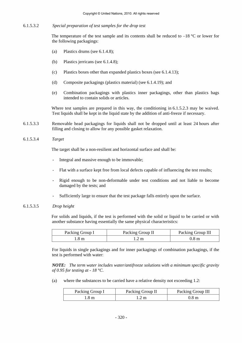
6.1.5.3.2 Special preparation of test samples for the drop test The temperature of the test sample and its contents shall be reduced to –18 °C or lower for
the following packagings: (a) Plastics drums (see 6.1.4.8); (b) Plastics jerricans (see 6.1.4.8); (c) Plastics boxes other than expanded plastics boxes (see 6.1.4.13); (d) Composite packagings (plastics material) (see 6.1.4.19); and (e) Combination packagings with plastics inner packagings, other than plastics bags
intended to contain solids or articles. Where test samples are prepared in this way, the conditioning in 6.1.5.2.3 may be waived.
Test liquids shall be kept in the liquid state by the addition of anti-freeze if necessary. 6.1.5.3.3 Removable head packagings for liquids shall not be dropped until at least 24 hours after
filling and closing to allow for any possible gasket relaxation. 6.1.5.3.4 Target The target shall be a non-resilient and horizontal surface and shall be:
- Integral and massive enough to be immovable; - Flat with a surface kept free from local defects capable of influencing the test results; - Rigid enough to be non-deformable under test conditions and not liable to become
damaged by the tests; and - Sufficiently large to ensure that the test package falls entirely upon the surface.
6.1.5.3.5 Drop height For solids and liquids, if the test is performed with the solid or liquid to be carried or with
another substance having essentially the same physical characteristics:
Packing Group I Packing Group II Packing Group III 1.8 m 1.2 m 0.8 m
For liquids in single packagings and for inner packagings of combination packagings, if the test is performed with water: NOTE: The term water includes water/antifreeze solutions with a minimum specific gravity of 0.95 for testing at - 18 °C.
(a) where the substances to be carried have a relative density not exceeding 1.2:
Packing Group I Packing Group II Packing Group III 1.8 m 1.2 m 0.8 m
Copyright © United Nations, 2010. All rights reserved

- 321 -
(b) where the substances to be carried have a relative density exceeding 1.2, the drop height shall be calculated on the basis of the relative density (d) of the substance to be carried, rounded up to the first decimal, as follows:
Packing Group I Packing Group II Packing Group III
d × 1.5 (m) d × 1.0 (m) d × 0.67 (m) (c) for light-gauge metal packagings, marked with symbol "RID/ADR" according to
6.1.3.1(a) (ii) intended for the carriage of substances having a viscosity at 23 °C greater than 200 mm2/s (corresponding to a flow time of 30 seconds with an ISO flow cup having a jet orifice of 6 mm diameter in accordance with ISO Standard 2431:1993)
(i) if the relative density does not exceed 1.2:
Packing group II Packing group III
0.6 m 0.4 m
(ii) where the substances to be carried have a relative density (d) exceeding 1.2 the drop height shall be calculated on the basis of the relative density (d) of the substance to be carried, rounded up to the first decimal place, as follows:
Packing group II Packing group III
d × 0.5 m d × 0.33 m 6.1.5.3.6 Criteria for passing the test 6.1.5.3.6.1 Each packaging containing liquid shall be leakproof when equilibrium has been reached
between the internal and external pressures, however for inner packagings of combination packagings and except for inner receptacles of composite packagings (glass, porcelain or stoneware), marked with the symbol "RID/ADR" according to 6.1.3.1 (a) (ii) it is not necessary that the pressures be equalized.
6.1.5.3.6.2 Where a packaging for solids undergoes a drop test and its upper face strikes the target, the
test sample passes the test if the entire contents are retained by an inner packaging or inner receptacle (e.g. a plastics bag), even if the closure while retaining its containment function, is no longer sift-proof.
6.1.5.3.6.3 The packaging or outer packaging of a composite or combination packaging shall not exhibit
any damage liable to affect safety during carriage. Inner receptacles, inner packagings, or articles shall remain completely within the outer packaging and there shall be no leakage of the filling substance from the inner receptacle(s) or inner packaging(s).
6.1.5.3.6.4 Neither the outermost ply of a bag nor an outer packaging may exhibit any damage liable to
affect safety during carriage. 6.1.5.3.6.5 A slight discharge from the closure(s) upon impact is not considered to be a failure of the
packaging provided that no further leakage occurs. 6.1.5.3.6.6 No rupture is permitted in packagings for goods of Class 1 which would permit the spillage
of loose explosive substances or articles from the outer packaging.
Copyright © United Nations, 2010. All rights reserved

- 322 -
6.1.5.4 Leakproofness test The leakproofness test shall be performed on all design types of packagings intended to
contain liquids; however, this test is not required for
- inner packagings of combination packagings; - inner receptacles of composite packagings (glass, porcelain or stoneware), marked
with the symbol "RID/ADR" according to 6.1.3.1 (a) (ii); - light gauge metal packagings, marked with the symbol "RID/ADR" according
to 6.1.3.1 (a) (ii) intended for substances with a viscosity at 23 °C exceeding 200 mm2/s.
6.1.5.4.1 Number of test samples: three test samples per design type and manufacturer. 6.1.5.4.2 Special preparation of test samples for the test: either vented closures shall be replaced by
similar non-vented closures or the vent shall be sealed. 6.1.5.4.3 Test method and pressure to be applied: the packagings including their closures shall be
restrained under water for 5 minutes while an internal air pressure is applied, the method of restraint shall not affect the results of the test.
The air pressure (gauge) to be applied shall be:
Packing Group I Packing Group II Packing Group III
Not less than 30 kPa (0.3 bar)
Not less than 20 kPa (0.2 bar)
Not less than 20 kPa (0.2 bar)
Other methods at least equally effective may be used.
6.1.5.4.4 Criterion for passing the test: there shall be no leakage. 6.1.5.5 Internal pressure (hydraulic) test 6.1.5.5.1 Packagings to be tested The internal pressure (hydraulic) test shall be carried out on all design types of metal,
plastics and composite packagings intended to contain liquids. This test is not required for:
- Inner packagings of combination packagings; - Inner receptacles of composite packagings (glass, porcelain or stoneware), marked
with the symbol "RID/ADR" according to 6.1.3.1 (a) (ii); - Light gauge metal packagings, marked with the symbol "RID/ADR" according
to 6.1.3.1 (a) (ii) intended for substances with a viscosity at 23 °C exceeding 200 mm2/s.
6.1.5.5.2 Number of test samples: three test samples per design type and manufacturer. 6.1.5.5.3 Special preparation of packagings for testing: either vented closures shall be replaced by
similar non-vented closures or the vent shall be sealed.
Copyright © United Nations, 2010. All rights reserved

- 323 -
6.1.5.5.4 Test method and pressure to be applied: metal packagings and composite packagings (glass, porcelain or stoneware), including their closures, shall be subjected to the test pressure for 5 minutes. Plastics packagings and composite packagings (plastics material) including their closures shall be subjected to the test pressure for 30 minutes. This pressure is the one to be included in the marking required by 6.1.3.1 (d). The manner in which the packagings are supported shall not invalidate the test. The test pressure shall be applied continuously and evenly; it shall be kept constant throughout the test period. The hydraulic pressure (gauge) applied, as determined by any one of the following methods, shall be:
(a) not less than the total gauge pressure measured in the packaging (i.e. the vapour
pressure of the filling liquid and the partial pressure of the air or other inert gases, minus 100 kPa) at 55 °C, multiplied by a safety factor of 1.5; this total gauge pressure shall be determined on the basis of a maximum degree of filling in accordance with 4.1.1.4 and a filling temperature of l5 °C; or
(b) not less than 1.75 times the vapour pressure at 50 °C of the liquid to be carried,
minus 100 kPa but with a minimum test pressure of 100 kPa; or (c) not less than 1.5 times the vapour pressure at 55 °C of the liquid to be carried,
minus 100 kPa but with a minimum test pressure of 100 kPa.
6.1.5.5.5 In addition, packagings intended to contain liquids of packing group I shall be tested to a minimum test pressure of 250 kPa (gauge) for a test period of 5 or 30 minutes depending upon the material of construction of the packaging.
6.1.5.5.6 Criterion for passing the test: no packaging may leak. 6.1.5.6 Stacking test All design types of packagings other than bags, and other than non-stackable composite
packagings (glass, porcelain, or stoneware) marked with the symbol "RID/ADR" according to 6.1.3.1 (a) (ii), shall be subjected to a stacking test.
6.1.5.6.1 Number of test samples: three test samples per design type and manufacturer. 6.1.5.6.2 Test method: the test sample shall be subjected to a force applied to the top surface of the test
sample equivalent to the total weight of identical packages which might be stacked on it during carriage; where the contents of the test sample are liquids with relative density different from that of the liquid to be carried, the force shall be calculated in relation to the latter. The minimum height of the stack including the test sample shall be 3 metres. The duration of the test shall be 24 hours except that plastics drums, jerricans, and composite packagings 6HH1 and 6HH2 intended for liquids shall be subjected to the stacking test for a period of 28 days at a temperature of not less than 40 °C.
For the test in accordance with 6.1.5.2.5, the original filling substance shall be used. For the
test in accordance with 6.1.5.2.6, a stacking test shall be carried out with a standard liquid. 6.1.5.6.3 Criteria for passing the test: no test sample shall leak. In composite packagings or
combination packagings, there shall be no leakage of the filling substance from the inner receptacle or inner packaging. No test sample shall show any deterioration which could adversely affect transport safety or any distortion liable to reduce its strength or cause instability in stacks of packages. Plastics packagings shall be cooled to ambient temperature before the assessment.
Copyright © United Nations, 2010. All rights reserved

- 324 -
6.1.5.7 Supplementary permeability test for plastics drums and jerricans in accordance with 6.1.4.8 and for composite packagings (plastics material) in accordance with 6.1.4.19 intended for the carriage of liquids having a flash-point ≤ 60 °C, other than 6HA1 packagings
Polyethylene packagings need be subjected to this test only if they are to be approved for the
carriage of benzene, toluene, xylene or mixtures and preparations containing those substances.
6.1.5.7.1 Number of test samples: three packagings per design type and manufacturer. 6.1.5.7.2 Special preparation of the test sample for the test: the test samples are to be pre-stored with
the original filling substance in accordance with 6.1.5.2.5, or, for polyethylene packagings, with the standard liquid mixture of hydrocarbons (white spirit) in accordance with 6.1.5.2.6.
6.1.5.7.3 Test method: the test samples filled with the substance for which the packaging is to be
approved shall be weighed before and after storage for 28 days at 23 °C and 50% relative atmospheric humidity. For polyethylene packagings, the test may be carried out with the standard liquid mixture of hydrocarbons (white spirit) in place of benzene, toluene or xylene.
6.1.5.7.4 Criterion for passing the test: permeability shall not exceed 0.008 g/l.h. 6.1.5.8 Test Report 6.1.5.8.1 A test report containing at least the following particulars shall be drawn up and shall be
available to the users of the packaging:
1. Name and address of the test facility;
2. Name and address of applicant (where appropriate);
3. A unique test report identification;
4. Date of the test report;
5. Manufacturer of the packaging;
6. Description of the packaging design type (e.g. dimensions, materials, closures, thickness, etc.), including method of manufacture (e.g. blow moulding) and which may include drawing(s) and/or photograph(s);
7. Maximum capacity;
8. Characteristics of test contents, e.g. viscosity and relative density for liquids and particle size for solids;
9. Test descriptions and results;
10. The test report shall be signed with the name and status of the signatory.
6.1.5.8.2 The test report shall contain statements that the packaging prepared as for carriage was tested in accordance with the appropriate requirements of this section and that the use of other packaging methods or components may render it invalid. A copy of the test report shall be available to the competent authority.
Copyright © United Nations, 2010. All rights reserved
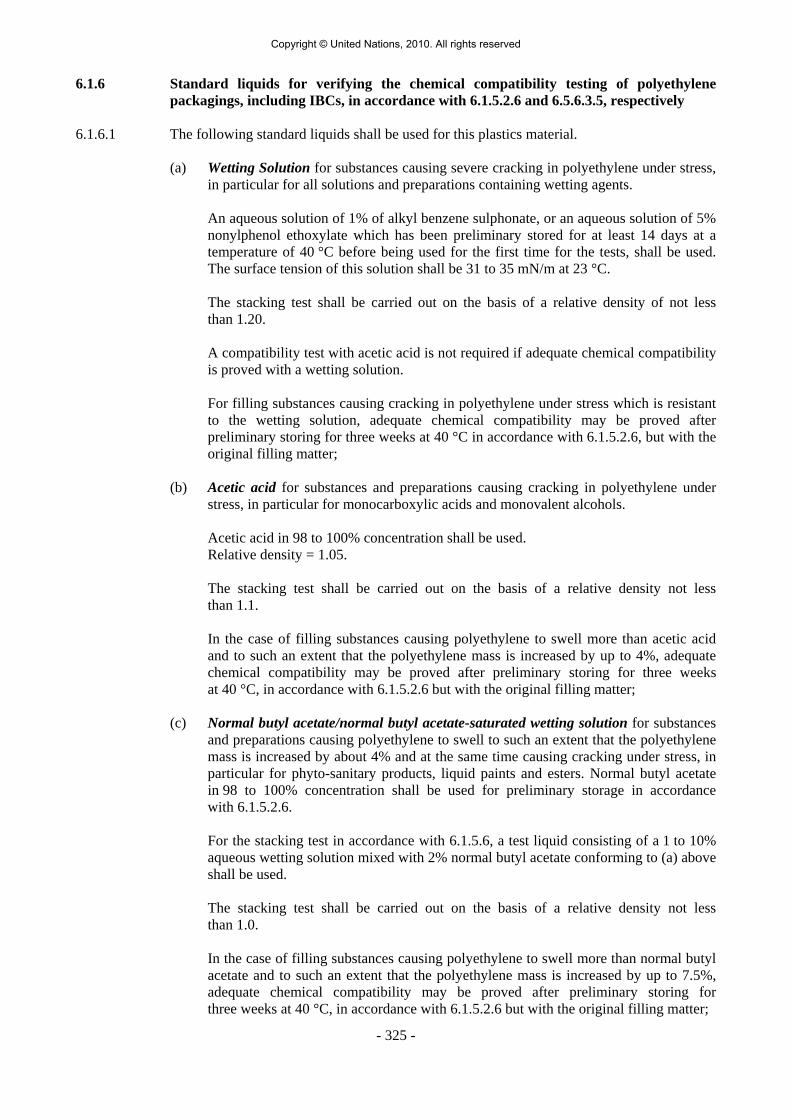
- 325 -
6.1.6 Standard liquids for verifying the chemical compatibility testing of polyethylene packagings, including IBCs, in accordance with 6.1.5.2.6 and 6.5.6.3.5, respectively
6.1.6.1 The following standard liquids shall be used for this plastics material.
(a) Wetting Solution for substances causing severe cracking in polyethylene under stress, in particular for all solutions and preparations containing wetting agents.
An aqueous solution of 1% of alkyl benzene sulphonate, or an aqueous solution of 5%
nonylphenol ethoxylate which has been preliminary stored for at least 14 days at a temperature of 40 °C before being used for the first time for the tests, shall be used. The surface tension of this solution shall be 31 to 35 mN/m at 23 °C.
The stacking test shall be carried out on the basis of a relative density of not less
than 1.20. A compatibility test with acetic acid is not required if adequate chemical compatibility
is proved with a wetting solution. For filling substances causing cracking in polyethylene under stress which is resistant
to the wetting solution, adequate chemical compatibility may be proved after preliminary storing for three weeks at 40 °C in accordance with 6.1.5.2.6, but with the original filling matter;
(b) Acetic acid for substances and preparations causing cracking in polyethylene under
stress, in particular for monocarboxylic acids and monovalent alcohols. Acetic acid in 98 to 100% concentration shall be used. Relative density = 1.05. The stacking test shall be carried out on the basis of a relative density not less
than 1.1. In the case of filling substances causing polyethylene to swell more than acetic acid
and to such an extent that the polyethylene mass is increased by up to 4%, adequate chemical compatibility may be proved after preliminary storing for three weeks at 40 °C, in accordance with 6.1.5.2.6 but with the original filling matter;
(c) Normal butyl acetate/normal butyl acetate-saturated wetting solution for substances
and preparations causing polyethylene to swell to such an extent that the polyethylene mass is increased by about 4% and at the same time causing cracking under stress, in particular for phyto-sanitary products, liquid paints and esters. Normal butyl acetate in 98 to 100% concentration shall be used for preliminary storage in accordance with 6.1.5.2.6.
For the stacking test in accordance with 6.1.5.6, a test liquid consisting of a 1 to 10%
aqueous wetting solution mixed with 2% normal butyl acetate conforming to (a) above shall be used.
The stacking test shall be carried out on the basis of a relative density not less
than 1.0. In the case of filling substances causing polyethylene to swell more than normal butyl
acetate and to such an extent that the polyethylene mass is increased by up to 7.5%, adequate chemical compatibility may be proved after preliminary storing for three weeks at 40 °C, in accordance with 6.1.5.2.6 but with the original filling matter;
Copyright © United Nations, 2010. All rights reserved

- 326 -
(d) Mixture of hydrocarbons (white spirit) for substances and preparations causing polyethylene to swell, in particular for hydrocarbons, esters and ketones.
A mixture of hydrocarbons having a boiling range 160 °C to 220 °C, relative density
0.78-0.80, flash-point > 50 °C and an aromatic content 16% to 21% shall be used. The stacking test shall be carried out on the basis of a relative density not less
than 1.0. In the case of filling substances causing polyethylene to swell to such an extent that
the polyethylene mass is increased by more than 7.5%, adequate chemical compatibility may be proved after preliminary storing for three weeks at 40 °C, in accordance with 6.1.5.2.6 but with the original filling matter;
(e) Nitric acid for all substances and preparations having an oxidizing effect on
polyethylene and causing molecular degradation identical to or less than 55% nitric acid.
Nitric acid in a concentration of not less than 55% shall be used. The stacking test shall be carried out on the basis of a relative density of not less
than 1.4. In the case of filling substances more strongly oxidizing than 55% nitric acid
or causing degradation of the molecular mass proceed in accordance with 6.1.5.2.5. The period of use shall be determined in such cases by observing the degree of
damage (e.g. two years for nitric acid in not less than 55% concentration); (f) Water for substances which do not attack polyethylene in any of the cases referred to
under (a) to (e), in particular for inorganic acids and lyes, aqueous saline solutions, polyvalent alcohols and organic substances in aqueous solution.
The stacking test shall be carried out on the basis of a relative density of not less
than 1.2. A design type test with water is not required if adequate chemical compatibility is proved with wetting solution or nitric acid.
Copyright © United Nations, 2010. All rights reserved

- 327 -
CHAPTER 6.2
REQUIREMENTS FOR THE CONSTRUCTION AND TESTING OF PRESSURE RECEPTACLES, AEROSOL DISPENSERS, SMALL RECEPTACLES
CONTAINING GAS (GAS CARTRIDGES) AND FUEL CELL CARTRIDGES CONTAINING LIQUEFIED FLAMMABLE GAS
NOTE: Aerosol dispensers, small receptacles containing gas (gas cartridges) and fuel cell
cartridges containing liquefied flammable gas are not subject to the requirements of 6.2.1 to 6.2.5.
6.2.1 General requirements 6.2.1.1 Design and construction 6.2.1.1.1 Pressure receptacles and their closures shall be designed, manufactured, tested and equipped
in such a way as to withstand all conditions, including fatigue, to which they will be subjected during normal conditions of carriage and use.
6.2.1.1.2 (Reserved) 6.2.1.1.3 In no case shall the minimum wall thickness be less than that specified in the design and
construction technical standards. 6.2.1.1.4 For welded pressure receptacles, only metals of weldable quality shall be used. 6.2.1.1.5 The test pressure of cylinders, tubes, pressure drums and bundles of cylinders shall be in
accordance with packing instruction P200 of 4.1.4.1. The test pressure for closed cryogenic receptacles shall be in accordance with packing instruction P203 of 4.1.4.1. The test pressure of a metal hydride storage system shall be in accordance with packing instruction P205 of 4.1.4.1.
6.2.1.1.6 Pressure receptacles assembled in bundles shall be structurally supported and held together
as a unit. Pressure receptacles shall be secured in a manner that prevents movement in relation to the structural assembly and movement that would result in the concentration of harmful local stresses. Manifold assemblies (e.g. manifold, valves, and pressure gauges) shall be designed and constructed such that they are protected from impact damage and forces normally encountered in carriage. Manifolds shall have at least the same test pressure as the cylinders. For toxic liquefied gases, each pressure receptacle shall have an isolation valve to ensure that each pressure receptacle can be filled separately and that no interchange of pressure receptacle contents can occur during carriage.
NOTE: Toxic liquefied gases have the classification codes 2T, 2TF, 2TC, 2TO, 2TFC or 2TOC.
6.2.1.1.7 Contact between dissimilar metals which could result in damage by galvanic action shall be
avoided. 6.2.1.1.8 Additional requirements for the construction of closed cryogenic receptacles for refrigerated
liquefied gases 6.2.1.1.8.1 The mechanical properties of the metal used shall be established for each pressure
receptacle, including the impact strength and the bending coefficient.
Copyright © United Nations, 2010. All rights reserved

- 328 -
NOTE: With regard to the impact strength, sub-section 6.8.5.3 gives details of test requirements which may be used.
6.2.1.1.8.2 The pressure receptacles shall be thermally insulated. The thermal insulation shall be
protected against impact by means of a jacket. If the space between the pressure receptacle and the jacket is evacuated of air (vacuum-insulation), the jacket shall be designed to withstand without permanent deformation an external pressure of at least 100 kPa (1 bar) calculated in accordance with a recognised technical code or a calculated critical collapsing pressure of not less than 200 kPa (2 bar) gauge pressure. If the jacket is so closed as to be gas-tight (e.g. in the case of vacuum-insulation), a device shall be provided to prevent any dangerous pressure from developing in the insulating layer in the event of inadequate gas-tightness of the pressure receptacle or its fittings. The device shall prevent moisture from penetrating into the insulation.
6.2.1.1.8.3 Closed cryogenic receptacles intended for the carriage of refrigerated liquefied gases having
a boiling point below –182 °C at atmospheric pressure shall not include materials which may react with oxygen or oxygen enriched atmospheres in a dangerous manner, when located in parts of the thermal insulation where there is a risk of contact with oxygen or with oxygen enriched liquid.
6.2.1.1.8.4 Closed cryogenic receptacles shall be designed and constructed with suitable lifting and
securing arrangements. 6.2.1.1.9 Additional requirements for the construction of pressure receptacles for acetylene Pressure receptacles for UN 1001 acetylene, dissolved, and UN 3374 acetylene, solvent free,
shall be filled with a porous material, uniformly distributed, of a type that conforms to the requirements and testing specified by the competent authority and which:
(a) Is compatible with the pressure receptacle and does not form harmful or dangerous
compounds either with the acetylene or with the solvent in the case of UN 1001; and (b) Is capable of preventing the spread of decomposition of the acetylene in the porous
material. In the case of UN 1001, the solvent shall be compatible with the pressure receptacle. 6.2.1.2 Materials 6.2.1.2.1 Construction materials of pressure receptacles and their closures which are in direct contact
with dangerous goods shall not be affected or weakened by the dangerous goods intended to be carried and shall not cause a dangerous effect e.g. catalysing a reaction or reacting with the dangerous goods.
6.2.1.2.2 Pressure receptacles and their closures shall be made of the materials specified in the design
and construction technical standards and the applicable packing instruction for the substances intended for carriage in the pressure receptacle. The materials shall be resistant to brittle fracture and to stress corrosion cracking as indicated in the design and construction technical standards.
6.2.1.3 Service equipment 6.2.1.3.1 Valves, piping and other fittings subjected to pressure, excluding pressure relief devices,
shall be designed and constructed so that the burst pressure is at least 1.5 times the test pressure of the pressure receptacle.
Copyright © United Nations, 2010. All rights reserved
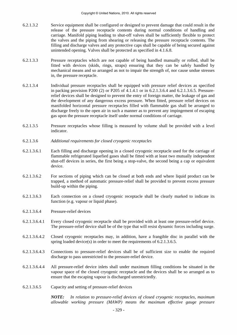
- 329 -
6.2.1.3.2 Service equipment shall be configured or designed to prevent damage that could result in the release of the pressure receptacle contents during normal conditions of handling and carriage. Manifold piping leading to shut-off valves shall be sufficiently flexible to protect the valves and the piping from shearing or releasing the pressure receptacle contents. The filling and discharge valves and any protective caps shall be capable of being secured against unintended opening. Valves shall be protected as specified in 4.1.6.8.
6.2.1.3.3 Pressure receptacles which are not capable of being handled manually or rolled, shall be
fitted with devices (skids, rings, straps) ensuring that they can be safely handled by mechanical means and so arranged as not to impair the strength of, nor cause undue stresses in, the pressure receptacle.
6.2.1.3.4 Individual pressure receptacles shall be equipped with pressure relief devices as specified
in packing provision P200 (2) or P205 of 4.1.4.1 or in 6.2.1.3.6.4 and 6.2.1.3.6.5. Pressure-relief devices shall be designed to prevent the entry of foreign matter, the leakage of gas and the development of any dangerous excess pressure. When fitted, pressure relief devices on manifolded horizontal pressure receptacles filled with flammable gas shall be arranged to discharge freely to the open air in such a manner as to prevent any impingement of escaping gas upon the pressure receptacle itself under normal conditions of carriage.
6.2.1.3.5 Pressure receptacles whose filling is measured by volume shall be provided with a level
indicator. 6.2.1.3.6 Additional requirements for closed cryogenic receptacles 6.2.1.3.6.1 Each filling and discharge opening in a closed cryogenic receptacle used for the carriage of
flammable refrigerated liquefied gases shall be fitted with at least two mutually independent shut-off devices in series, the first being a stop-valve, the second being a cap or equivalent device.
6.2.1.3.6.2 For sections of piping which can be closed at both ends and where liquid product can be
trapped, a method of automatic pressure-relief shall be provided to prevent excess pressure build-up within the piping.
6.2.1.3.6.3 Each connection on a closed cryogenic receptacle shall be clearly marked to indicate its
function (e.g. vapour or liquid phase). 6.2.1.3.6.4 Pressure-relief devices 6.2.1.3.6.4.1 Every closed cryogenic receptacle shall be provided with at least one pressure-relief device.
The pressure-relief device shall be of the type that will resist dynamic forces including surge. 6.2.1.3.6.4.2 Closed cryogenic receptacles may, in addition, have a frangible disc in parallel with the
spring loaded device(s) in order to meet the requirements of 6.2.1.3.6.5. 6.2.1.3.6.4.3 Connections to pressure-relief devices shall be of sufficient size to enable the required
discharge to pass unrestricted to the pressure-relief device. 6.2.1.3.6.4.4 All pressure-relief device inlets shall under maximum filling conditions be situated in the
vapour space of the closed cryogenic receptacle and the devices shall be so arranged as to ensure that the escaping vapour is discharged unrestrictedly.
6.2.1.3.6.5 Capacity and setting of pressure-relief devices
NOTE: In relation to pressure-relief devices of closed cryogenic receptacles, maximum allowable working pressure (MAWP) means the maximum effective gauge pressure
Copyright © United Nations, 2010. All rights reserved

- 330 -
permissible at the top of a loaded closed cryogenic receptacle in its operating position including the highest effective pressure during filling and discharge.
6.2.1.3.6.5.1 The pressure-relief device shall open automatically at a pressure not less than the MAWP
and be fully open at a pressure equal to 110% of the MAWP. It shall, after discharge, close at a pressure not lower than 10% below the pressure at which discharge starts and shall remain closed at all lower pressures.
6.2.1.3.6.5.2 Frangible discs shall be set to rupture at a nominal pressure which is the lower of either the
test pressure or 150% of the MAWP. 6.2.1.3.6.5.3 In the case of the loss of vacuum in a vacuum-insulated closed cryogenic receptacle the
combined capacity of all pressure-relief devices installed shall be sufficient so that the pressure (including accumulation) inside the closed cryogenic receptacle does not exceed 120% of the MAWP.
6.2.1.3.6.5.4 The required capacity of the pressure-relief devices shall be calculated in accordance with an
established technical code recognized by the competent authority 1. 6.2.1.4 Approval of pressure receptacles 6.2.1.4.1 The conformity of pressure receptacles shall be assessed at time of manufacture as required
by the competent authority. Pressure receptacles shall be inspected, tested and approved by an inspection body. The technical documentation shall include full specifications on design and construction, and full documentation on the manufacturing and testing.
6.2.1.4.2 Quality assurance systems shall conform to the requirements of the competent authority. 6.2.1.5 Initial inspection and test 6.2.1.5.1 New pressure receptacles, other than closed cryogenic receptacles and metal hydride storage
systems, shall be subjected to testing and inspection during and after manufacture in accordance with the applicable design standards including the following:
On an adequate sample of pressure receptacles:
(a) Testing of the mechanical characteristics of the material of construction; (b) Verification of the minimum wall thickness; (c) Verification of the homogeneity of the material for each manufacturing batch; (d) Inspection of the external and internal conditions of the pressure receptacles; (e) Inspection of the neck threads; (f) Verification of the conformance with the design standard;
For all pressure receptacles: (g) A hydraulic pressure test. Pressure receptacles shall withstand the test pressure
without expansion greater than that allowed in the design specification;
1 See for example CGA Publications S-1.2-2003 "Pressure Relief Device Standards-Part 2-Cargo and Portable Tanks for Compressed Gases" and S-1.1-2003 "Pressure Relief Device Standards-Part 1-Cylinders for Compressed Gases".
Copyright © United Nations, 2010. All rights reserved

- 331 -
NOTE: With the agreement of the competent authority, the hydraulic pressure test may be replaced by a test using a gas, where such an operation does not entail any danger.
(h) Inspection and assessment of manufacturing defects and either repairing them or rendering the pressure receptacles unserviceable. In the case of welded pressure receptacles, particular attention shall be paid to the quality of the welds;
(i) An inspection of the markings on the pressure receptacles; (j) In addition, pressure receptacles intended for the carriage of UN No. 1001 acetylene,
dissolved, and UN No. 3374 acetylene, solvent free, shall be inspected to ensure proper installation and condition of the porous material and, if applicable, the quantity of solvent.
6.2.1.5.2 On an adequate sample of closed cryogenic receptacles, the inspections and tests specified in
6.2.1.5.1 (a), (b), (d) and (f) shall be performed. In addition, welds shall be inspected by radiographic, ultrasonic or another suitable non-destructive test method on a sample of closed cryogenic receptacles according to the applicable design and construction standard. This weld inspection does not apply to the jacket.
Additionally, all closed cryogenic receptacles shall undergo the initial inspections and tests specified in 6.2.1.5.1 (g), (h) and (i), as well as a leakproofness test and a test of the satisfactory operation of the service equipment after assembly.
6.2.1.5.3 For metal hydride storage systems, it shall be verified that the inspections and tests specified in 6.2.1.5.1 (a), (b), (c), (d), (e) if applicable, (f), (g), (h) and (i) have been performed on an adequate sample of the receptacles used in the metal hydride storage system. In addition, on an adequate sample of metal hydride storage systems, the inspections and tests specified in 6.2.1.5.1 (c) and (f) shall be performed, as well as 6.2.1.5.1 (e), if applicable, and inspection of the external conditions of the metal hydride storage system.
Additionally, all metal hydride storage systems shall undergo the initial inspections and tests
specified in 6.2.1.5.1 (h) and (i), as well as a leakproofness test and a test of the satisfactory operation of the service equipment.
6.2.1.6 Periodic inspection and test 6.2.1.6.1 Refillable pressure receptacles, other than cryogenic receptacles, shall be subjected to
periodic inspections and tests by a body authorised by the competent authority, in accordance with the following:
(a) Check of the external conditions of the pressure receptacle and verification of the
equipment and the external markings; (b) Check of the internal conditions of the pressure receptacle (e.g. internal inspection,
verification of minimum wall thickness); (c) Checking of the threads if there is evidence of corrosion or if the fittings are
removed; (d) A hydraulic pressure test and, if necessary, verification of the characteristics of the
material by suitable tests; (e) Check of service equipment, other accessories and pressure-relief devices, if to be
reintroduced into service.
Copyright © United Nations, 2010. All rights reserved

- 332 -
NOTE 1: With the agreement of the competent authority, the hydraulic pressure test may be replaced by a test using a gas, where such an operation does not entail any danger.
NOTE 2: With the agreement of the competent authority, the hydraulic pressure test of cylinders or tubes may be replaced by an equivalent method based on acoustic emission testing or a combination of acoustic emission testing and ultrasonic examination. ISO 16148:2006 may be used as a guide for acoustic emission testing procedures.
NOTE 3: The hydraulic pressure test may be replaced by ultrasonic examination carried out in accordance with ISO 10461:2005+A1:2006 for seamless aluminium alloy gas cylinders and in accordance with ISO 6406:2005 for seamless steel gas cylinders. NOTE 4: For the periodic inspection and test frequencies, see packing instruction P200 in 4.1.4.1.
6.2.1.6.2 Pressure receptacles intended for the carriage of UN No. 1001 acetylene, dissolved and UN No. 3374 acetylene, solvent free, shall be examined only as specified in 6.2.1.6.1 (a), (c) and (e). In addition the condition of the porous material (e.g. cracks, top clearance, loosening, settlement) shall be examined.
6.2.1.7 Requirements for manufacturers 6.2.1.7.1 The manufacturer shall be technically able and shall possess all resources required for the
satisfactory manufacture of pressure receptacles; this relates in particular to qualified personnel:
(a) To supervise the entire manufacturing process; (b) To carry out joining of materials; and (c) To carry out the relevant tests.
6.2.1.7.2 The proficiency test of a manufacturer shall in all instances be carried out by an inspection
body approved by the competent authority of the country of approval. 6.2.1.8 Requirements for inspection bodies 6.2.1.8.1 Inspection bodies shall be independent from manufacturing enterprises and competent to
perform the tests, inspections and approvals required. 6.2.2 Requirements for UN pressure receptacles
In addition to the general requirements of section 6.2.1, UN pressure receptacles shall comply with the requirements of this section, including the standards, as applicable.
6.2.2.1 Design, construction and initial inspection and test 6.2.2.1.1 The following standards apply for the design, construction, and initial inspection and test of
UN cylinders, except that inspection requirements related to the conformity assessment system and approval shall be in accordance with 6.2.2.5:
Copyright © United Nations, 2010. All rights reserved

- 333 -
ISO 9809-1:1999 Gas cylinders – Refillable seamless steel gas cylinders – Design, construction and testing – Part 1: Quenched and tempered steel cylinders with tensile strength less than 1 100 MPa NOTE: The note concerning the F factor in section 7.3 of this standard shall not be applied for UN cylinders.
ISO 9809-2:2000 Gas cylinders – Refillable seamless steel gas cylinders – Design, construction and testing – Part 2: Quenched and tempered steel cylinders with tensile strength greater than or equal to 1 100 MPa
ISO 9809-3:2000 Gas cylinders – Refillable seamless steel gas cylinders – Design, construction and testing – Part 3: Normalized steel cylinders
ISO 7866:1999 Gas cylinders – Refillable seamless aluminium alloy gas cylinders – Design, construction and testing NOTE: The note concerning the F factor in section 7.2 of this standard shall not be applied for UN cylinders. Aluminium alloy 6351A – T6 or equivalent shall not be authorised.
ISO 4706:2008 Gas cylinders – Refillable welded steel cylinders – Test pressure 60 bar and below
ISO 18172-1:2007 Gas cylinders – Refillable welded stainless steel cylinders – Part 1: Test pressure 6 MPa and below
ISO 20703:2006 Gas cylinders – Refillable welded aluminium-alloy cylinders – Design, construction and testing
ISO 11118:1999 Gas cylinders – Non-refillable metallic gas cylinders – Specification and test methods
ISO 11119-1:2002 Gas cylinders of composite construction – Specification and test methods – Part 1: Hoop wrapped composite gas cylinders
ISO 11119-2:2002 Gas cylinders of composite construction – Specification and test methods – Part 2: Fully wrapped fibre reinforced composite gas cylinders with load-sharing metal liners
ISO 11119-3:2002 Gas cylinders of composite construction – Specification and test methods – Part 3: Fully wrapped fibre reinforced composite gas cylinders with non-load-sharing metallic or non-metallic liners
NOTE 1: In the above referenced standards composite cylinders shall be designed for unlimited service life.
NOTE 2: After the first 15 years of service, composite cylinders manufactured according to these standards, may be approved for extended service by the competent authority which was responsible for the original approval of the cylinders and which will base its decision on the test information supplied by the manufacturer or owner or user.
6.2.2.1.2 The following standard apply for the design, construction, and initial inspection and test of
UN tubes, except that inspection requirements related to the conformity assessment system and approval shall be in accordance with 6.2.2.5:
ISO 11120:1999 Gas cylinders – Refillable seamless steel tubes for compressed gas
transport, of water capacity between 150 l and 3 000 l – Design, construction and testing NOTE: The note concerning the F factor in section 7.1 of this standard shall not be applied for UN tubes.
6.2.2.1.3 The following standards apply for the design, construction and initial inspection and test of
UN acetylene cylinders, except that inspection requirements related to the conformity assessment system and approval shall be in accordance with 6.2.2.5:
Copyright © United Nations, 2010. All rights reserved
- 334 -
For the cylinder shell:
ISO 9809-1:1999 Gas cylinders – Refillable seamless steel gas cylinders – Design, construction and testing – Part 1: Quenched and tempered steel cylinders with tensile strength less than 1 100 MPa NOTE: The note concerning the F factor in section 7.3 of this standard shall not be applied for UN cylinders.
ISO 9809-3:2000 Gas cylinders – Refillable seamless steel gas cylinders – Design, construction and testing – Part 3: Normalized steel cylinders
For the porous material in the cylinder:
ISO 3807-1:2000 Cylinders for acetylene – Basic requirements – Part 1: Cylinders
without fusible plugs ISO 3807-2:2000 Cylinders for acetylene – Basic requirements – Part 2: Cylinders
with fusible plugs 6.2.2.1.4 The following standard apply for the design, construction, and initial inspection and test of
UN cryogenic receptacles, except that inspection requirements related to the conformity assessment system and approval shall be in accordance with 6.2.2.5:
ISO 21029-1:2004 Cryogenic vessels – Transportable vacuum insulated vessels of not
more than 1 000 l volume – Part 1: Design, fabrication, inspection and tests
6.2.2.1.5 The following standard applies for the design, construction, and initial inspection and test of
UN metal hydride storage systems, except that inspection requirements related to the conformity assessment system and approval shall be in accordance with 6.2.2.5:
ISO 16111:2008 Transportable gas storage devices – Hydrogen absorbed in reversible metal hydride
6.2.2.2 Materials
In addition to the material requirements specified in the pressure receptacle design and construction standards, and any restrictions specified in the applicable packing instruction for the gas(es) to be carried (e.g. packing instruction P200 or P205 of 4.1.4.1), the following standards apply to material compatibility:
ISO 11114-1:1997 Transportable gas cylinders – Compatibility of cylinder and valve
materials with gas contents – Part 1: Metallic materials ISO 11114-2:2000 Transportable gas cylinders – Compatibility of cylinder and valve
materials with gas contents – Part 2: Non-metallic materials NOTE: The limitations imposed in ISO 11114-1 on high strength steel alloys at ultimate
tensile strength levels up to 1 100 MPa do not apply to UN No. 2203 silane. 6.2.2.3 Service equipment
The following standards apply to closures and their protection:
ISO 11117:1998 Gas cylinders – Valve protection caps and valve guards for industrial and medical gas cylinders – Design, construction and tests
ISO 10297:2006 Transportable gas cylinders – Cylinder valves – Specification and type testing NOTE: The EN version of this ISO standard fulfils the requirements and may also be used.
Copyright © United Nations, 2010. All rights reserved

- 335 -
For UN metal hydride storage systems, the requirements specified in the following standard apply to closures and their protection: ISO 16111:2008 Transportable gas storage devices – Hydrogen absorbed in reversible
metal hydride 6.2.2.4 Periodic inspection and test
The following standards apply to the periodic inspection and testing of UN cylinders and UN metal hydride storage systems:
ISO 6406:2005 Periodic inspection and testing of seamless steel gas cylinders ISO 10461:2005 + A1:2006
Seamless aluminium-alloy gas cylinders – Periodic inspection and testing
ISO 10462:2005 Gas cylinders – Transportable cylinders for dissolved acetylene – Periodic inspection and maintenance
ISO 11623:2002 Transportable gas cylinders – Periodic inspection and testing of composite gas cylinders
ISO 16111:2008 Transportable gas storage devices – Hydrogen absorbed in reversible metal hydride
6.2.2.5 Conformity assessment system and approval for manufacture of pressure receptacles 6.2.2.5.1 Definitions
For the purposes of this sub-section:
Conformity assessment system means a system for competent authority approval of a manufacturer, by pressure receptacle design type approval, approval of manufacturer's quality system and approval of inspection bodies;
Design type means a pressure receptacle design as specified by a particular pressure receptacle standard;
Verify means confirm by examination or provision of objective evidence that specified requirements have been fulfilled.
6.2.2.5.2 General requirements
Competent authority
6.2.2.5.2.1 The competent authority that approves the pressure receptacle shall approve the conformity assessment system for the purpose of ensuring that pressure receptacles conform to the requirements of ADR. In instances where the competent authority that approves a pressure receptacle is not the competent authority in the country of manufacture, the marks of the approval country and the country of manufacture shall be indicated in the pressure receptacle marking (see 6.2.2.7 and 6.2.2.8).
The competent authority of the country of approval shall supply, upon request, evidence demonstrating compliance to this conformity assessment system to its counterpart in a country of use.
6.2.2.5.2.2 The competent authority may delegate its functions in this conformity assessment system in
whole or in part.
Copyright © United Nations, 2010. All rights reserved

- 336 -
6.2.2.5.2.3 The competent authority shall ensure that a current list of approved inspection bodies and their identity marks and approved manufacturers and their identity marks is available.
Inspection body
6.2.2.5.2.4 The inspection body shall be approved by the competent authority for the inspection of
pressure receptacles and shall:
(a) Have a staff with an organisational structure, capable, trained, competent, and skilled, to satisfactorily perform its technical functions;
(b) Have access to suitable and adequate facilities and equipment;
(c) Operate in an impartial manner and be free from any influence which could prevent
it from doing so;
(d) Ensure commercial confidentiality of the commercial and proprietary activities of the manufacturer and other bodies;
(e) Maintain clear demarcation between actual inspection body functions and unrelated
functions;
(f) Operate a documented quality system;
(g) Ensure that the tests and inspections specified in the relevant pressure receptacle standard and ADR are performed; and
(h) Maintain an effective and appropriate report and record system in accordance with
6.2.2.5.6. 6.2.2.5.2.5 The inspection body shall perform design type approval, pressure receptacle production
testing and inspection, and certification to verify conformity with the relevant pressure receptacle standard (see 6.2.2.5.4 and 6.2.2.5.5).
Manufacturer
6.2.2.5.2.6 The manufacturer shall:
(a) Operate a documented quality system in accordance with 6.2.2.5.3; (b) Apply for design type approvals in accordance with 6.2.2.5.4; (c) Select an inspection body from the list of approved inspection bodies maintained by
the competent authority in the country of approval; and (d) Maintain records in accordance with 6.2.2.5.6. Testing laboratory
6.2.2.5.2.7 The testing laboratory shall have:
(a) Staff with an organisational structure, sufficient in number, competence, and skill; and
(b) Suitable and adequate facilities and equipment to perform the tests required by the
manufacturing standard to the satisfaction of the inspection body.
Copyright © United Nations, 2010. All rights reserved

- 337 -
6.2.2.5.3 Manufacturer's quality system 6.2.2.5.3.1 The quality system shall contain all the elements, requirements, and provisions adopted by
the manufacturer. It shall be documented in a systematic and orderly manner in the form of written policies, procedures and instructions.
The contents shall in particular include adequate descriptions of:
(a) The organisational structure and responsibilities of personnel with regard to design and product quality;
(b) The design control and design verification techniques, processes, and procedures
that will be used when designing the pressure receptacles;
(c) The relevant pressure receptacle manufacturing, quality control, quality assurance and process operation instructions that will be used;
(d) Quality records, such as inspection reports, test data and calibration data;
(e) Management reviews to ensure the effective operation of the quality system arising from the audits in accordance with 6.2.2.5.3.2;
(f) The process describing how customer requirements are met;
(g) The process for control of documents and their revision; (h) The means for control of non-conforming pressure receptacles, purchased
components, in-process and final materials; and
(i) Training programmes and qualification procedures for relevant personnel. 6.2.2.5.3.2 Audit of the quality system
The quality system shall be initially assessed to determine whether it meets the requirements in 6.2.2.5.3.1 to the satisfaction of the competent authority.
The manufacturer shall be notified of the results of the audit. The notification shall contain the conclusions of the audit and any corrective actions required.
Periodic audits shall be carried out, to the satisfaction of the competent authority, to ensure that the manufacturer maintains and applies the quality system. Reports of the periodic audits shall be provided to the manufacturer.
6.2.2.5.3.3 Maintenance of the quality system
The manufacturer shall maintain the quality system as approved in order that it remains adequate and efficient. The manufacturer shall notify the competent authority that approved the quality system, of any intended changes. The proposed changes shall be evaluated in order to determine whether the amended quality system will still satisfy the requirements in 6.2.2.5.3.1.
Copyright © United Nations, 2010. All rights reserved
- 338 -
6.2.2.5.4 Approval process
Initial design type approval 6.2.2.5.4.1 The initial design type approval shall consist of approval of the manufacturer's quality
system and approval of the pressure receptacle design to be produced. An application for an initial design type approval shall meet the requirements of 6.2.2.5.4.2 to 6.2.2.5.4.6 and 6.2.2.5.4.9.
6.2.2.5.4.2 A manufacturer desiring to produce pressure receptacles in accordance with a pressure
receptacle standard and ADR shall apply for, obtain, and retain a design type approval certificate issued by the competent authority in the country of approval for at least one pressure receptacle design type in accordance with the procedure given in 6.2.2.5.4.9. This certificate shall, on request, be submitted to the competent authority of the country of use.
6.2.2.5.4.3 An application shall be made for each manufacturing facility and shall include:
(a) The name and registered address of the manufacturer and in addition, if the application is submitted by an authorised representative, its name and address;
(b) The address of the manufacturing facility (if different from the above); (c) The name and title of the person(s) responsible for the quality system; (d) The designation of the pressure receptacle and the relevant pressure receptacle
standard;
(e) Details of any refusal of approval of a similar application by any other competent authority;
(f) The identity of the inspection body for design type approval; (g) Documentation on the manufacturing facility as specified under 6.2.2.5.3.1; and
(h) The technical documentation required for design type approval, which shall enable
verification of the conformity of the pressure receptacles with the requirements of the relevant pressure receptacle design standard. The technical documentation shall cover the design and method of manufacture and shall contain, as far as is relevant for assessment, at least the following:
(i) pressure receptacle design standard, design and manufacturing drawings,
showing components and subassemblies, if any;
(ii) descriptions and explanations necessary for the understanding of the drawings and intended use of the pressure receptacles;
(iii) a list of the standards necessary to fully define the manufacturing process;
(iv) design calculations and material specifications; and
(v) design type approval test reports, describing the results of examinations and
tests carried out in accordance with 6.2.2.5.4.9. 6.2.2.5.4.4 An initial audit in accordance with 6.2.2.5.3.2 shall be performed to the satisfaction of the
competent authority.
Copyright © United Nations, 2010. All rights reserved

- 339 -
6.2.2.5.4.5 If the manufacturer is denied approval, the competent authority shall provide written detailed reasons for such denial.
6.2.2.5.4.6 Following approval, changes to the information submitted under 6.2.2.5.4.3 relating to the
initial approval shall be provided to the competent authority.
Subsequent design type approvals 6.2.2.5.4.7 An application for a subsequent design type approval shall meet the requirements of
6.2.2.5.4.8 and 6.2.2.5.4.9, provided a manufacturer is in the possession of an initial design type approval. In such a case, the manufacturer's quality system according to 6.2.2.5.3 shall have been approved during the initial design type approval and shall be applicable for the new design.
6.2.2.5.4.8 The application shall include:
(a) The name and address of the manufacturer and in addition, if the application is submitted by an authorised representative, its name and address;
(b) Details of any refusal of approval of a similar application by any other competent
authority;
(c) Evidence that initial design type approval has been granted; and (d) The technical documentation, as described in 6.2.2.5.4.3 (h).
Procedure for design type approval
6.2.2.5.4.9 The inspection body shall:
(a) Examine the technical documentation to verify that:
(i) the design is in accordance with the relevant provisions of the standard, and
(ii) the prototype lot has been manufactured in conformity with the technical documentation and is representative of the design;
(b) Verify that the production inspections have been carried out as required in accordance with 6.2.2.5.5;
(c) Select pressure receptacles from a prototype production lot and supervise the tests of these pressure receptacles as required for design type approval;
(d) Perform or have performed the examinations and tests specified in the pressure receptacle standard to determine that:
(i) the standard has been applied and fulfilled, and
(ii) the procedures adopted by the manufacturer meet the requirements of the standard; and
(e) Ensure that the various type approval examinations and tests are correctly and competently carried out.
After prototype testing has been carried out with satisfactory results and all applicable requirements of 6.2.2.5.4 have been satisfied, a design type approval certificate shall be issued, which shall include the name and address of the manufacturer, results and conclusions of the examination, and the necessary data for identification of the design type.
Copyright © United Nations, 2010. All rights reserved

- 340 -
If the manufacturer is denied a design type approval, the competent authority shall provide written detailed reasons for such denial.
6.2.2.5.4.10 Modifications to approved design types
The manufacturer shall either:
(a) Inform the issuing competent authority of modifications to the approved design type, where such modifications do not constitute a new design, as specified in the pressure receptacle standard; or
(b) Request a subsequent design type approval where such modifications constitute a
new design according to the relevant pressure receptacle standard. This additional approval shall be given in the form of an amendment to the original design type approval certificate.
6.2.2.5.4.11 Upon request, the competent authority shall communicate to any other competent authority,
information concerning design type approval, modifications of approvals and withdrawn approvals.
6.2.2.5.5 Production inspection and certification
General requirements
An inspection body, or its delegate, shall carry out the inspection and certification of each pressure receptacle. The inspection body selected by the manufacturer for inspection and testing during production may be different from the inspection body used for the design type approval testing.
Where it can be demonstrated to the satisfaction of the inspection body that the manufacturer has trained competent inspectors, independent of the manufacturing operations, inspection may be performed by those inspectors. In such a case, the manufacturer shall maintain training records of the inspectors.
The inspection body shall verify that the inspections by the manufacturer, and tests performed on those pressure receptacles, fully conform to the standard and the requirements of ADR. Should non-conformance in conjunction with this inspection and testing be determined, the permission to have inspection performed by the manufacturer's inspectors may be withdrawn.
The manufacturer shall, after approval by the inspection body, make a declaration of conformity with the certified design type. The application of the pressure receptacle certification marking shall be considered a declaration that the pressure receptacle complies with the applicable pressure receptacle standards and the requirements of this conformity assessment system and ADR. The inspection body shall affix or delegate the manufacturer to affix the pressure receptacle certification marking and the registered mark of the inspection body to each approved pressure receptacle.
A certificate of compliance, signed by the inspection body and the manufacturer, shall be issued before the pressure receptacles are filled.
6.2.2.5.6 Records
Design type approval and certificate of compliance records shall be retained by the manufacturer and the inspection body for not less than 20 years.
Copyright © United Nations, 2010. All rights reserved

- 341 -
6.2.2.6 Approval system for periodic inspection and test of pressure receptacles 6.2.2.6.1 Definition For the purposes of this section:
Approval system means a system for competent authority approval of a body performing periodic inspection and test of pressure receptacles (hereinafter referred to as "periodic inspection and test body"), including approval of that body’s quality system.
6.2.2.6.2 General requirements
Competent authority 6.2.2.6.2.1 The competent authority shall establish an approval system for the purpose of ensuring that
the periodic inspection and test of pressure receptacles conform to the requirements of ADR. In instances where the competent authority that approves a body performing periodic inspection and test of a pressure receptacle is not the competent authority of the country approving the manufacture of the pressure receptacle, the marks of the approval country of periodic inspection and test shall be indicated in the pressure receptacle marking (see 6.2.2.7).
The competent authority of the country of approval for the periodic inspection and test shall supply, upon request, evidence demonstrating compliance to this approval system including the records of the periodic inspection and test to its counterpart in a country of use. The competent authority of the country of approval may terminate the approval certificate referred to in 6.2.2.6.4.1, upon evidence demonstrating non-compliance with the approval system.
6.2.2.6.2.2 The competent authority may delegate its functions in this approval system, in whole or in
part. 6.2.2.6.2.3 The competent authority shall ensure that a current list of approved periodic inspection and
test bodies and their identity marks is available.
Periodic inspection and test body 6.2.2.6.2.4 The periodic inspection and test body shall be approved by the competent authority and
shall:
(a) Have a staff with an organisational structure, capable, trained, competent, and skilled, to satisfactorily perform its technical functions;
(b) Have access to suitable and adequate facilities and equipment; (c) Operate in an impartial manner and be free from any influence which could prevent
it from doing so; (d) Ensure commercial confidentiality; (e) Maintain clear demarcation between actual periodic inspection and test body
functions and unrelated functions; (f) Operate a documented quality system accordance with 6.2.2.6.3; (g) Apply for approval in accordance with 6.2.2.6.4;
Copyright © United Nations, 2010. All rights reserved

- 342 -
(h) Ensure that the periodic inspections and tests are performed in accordance with 6.2.2.6.5; and
(i) Maintain an effective and appropriate report and record system in accordance
with 6.2.2.6.6. 6.2.2.6.3 Quality system and audit of the periodic inspection and test body 6.2.2.6.3.1 Quality system
The quality system shall contain all the elements, requirements, and provisions adopted by the periodic inspection and test body. It shall be documented in a systematic and orderly manner in the form of written policies, procedures, and instructions. The quality system shall include:
(a) A description of the organisational structure and responsibilities; (b) The relevant inspection and test, quality control, quality assurance, and process
operation instructions that will be used; (c) Quality records, such as inspection reports, test data, calibration data and certificates; (d) Management reviews to ensure the effective operation of the quality system arising
from the audits performed in accordance with 6.2.2.6.3.2; (e) A process for control of documents and their revision; (f) A means for control of non-conforming pressure receptacles; and (g) Training programmes and qualification procedures for relevant personnel.
6.2.2.6.3.2 Audit The periodic inspection and test body and its quality system shall be audited in order to
determine whether it meets the requirements of ADR to the satisfaction of the competent authority.
An audit shall be conducted as part of the initial approval process (see 6.2.2.6.4.3). An audit
may be required as part of the process to modify an approval (see 6.2.2.6.4.6). Periodic audits shall be conducted, to the satisfaction of the competent authority, to ensure
that the periodic inspection and test body continues to meet the requirements of ADR. The periodic inspection and test body shall be notified of the results of any audit. The
notification shall contain the conclusions of the audit and any corrective actions required. 6.2.2.6.3.3 Maintenance of the quality system The periodic inspection and test body shall maintain the quality system as approved in order
that it remains adequate and efficient. The periodic inspection and test body shall notify the competent authority that approved the
quality system, of any intended changes, in accordance with the process for modification of an approval in 6.2.2.6.4.6.
Copyright © United Nations, 2010. All rights reserved

- 343 -
6.2.2.6.4 Approval process for periodic inspection and test bodies
Initial approval 6.2.2.6.4.1 A body desiring to perform periodic inspection and test of pressure receptacles in accordance
with a pressure receptacle standard and ADR shall apply for, obtain, and retain an approval certificate issued by the competent authority.
This written approval shall, on request, be submitted to the competent authority of a
country of use. 6.2.2.6.4.2 An application shall be made for each periodic inspection and test body and shall include:
(a) The name and address of the periodic inspection and test body and, if the application is submitted by an authorised representative, its name and address;
(b) The address of each facility performing periodic inspection and test; (c) The name and title of the person(s) responsible for the quality system; (d) The designation of the pressure receptacles, the periodic inspection and test methods,
and the relevant pressure receptacle standards met by the quality system; (e) Documentation on each facility, the equipment, and the quality system as specified
under 6.2.2.6.3.1; (f) The qualifications and training records of the periodic inspection and test personnel;
and (g) Details of any refusal of approval of a similar application by any other competent
authority. 6.2.2.6.4.3 The competent authority shall:
(a) Examine the documentation to verify that the procedures are in accordance with the requirements of the relevant pressure receptacle standards and ADR; and
(b) Conduct an audit in accordance with 6.2.2.6.3.2 to verify that the inspections and tests
are carried out as required by the relevant pressure receptacle standards and ADR, to the satisfaction of the competent authority.
6.2.2.6.4.4 After the audit has been carried out with satisfactory results and all applicable requirements
of 6.2.2.6.4 have been satisfied, an approval certificate shall be issued. It shall include the name of the periodic inspection and test body, the registered mark, the address of each facility, and the necessary data for identification of its approved activities (e.g. designation of pressure receptacles, periodic inspection and test method and pressure receptacle standards).
6.2.2.6.4.5 If the periodic inspection and test body is denied approval, the competent authority shall
provide written detailed reasons for such denial.
Modifications to periodic inspection and test body approvals 6.2.2.6.4.6 Following approval, the periodic inspection and test body shall notify the issuing competent
authority of any modifications to the information submitted under 6.2.2.6.4.2 relating to the initial approval.
Copyright © United Nations, 2010. All rights reserved

- 344 -
The modifications shall be evaluated in order to determine whether the requirements of the relevant pressure receptacle standards and ADR will be satisfied. An audit in accordance with 6.2.2.6.3.2 may be required. The competent authority shall accept or reject these modifications in writing, and an amended approval certificate shall be issued as necessary.
6.2.2.6.4.7 Upon request, the competent authority shall communicate to any other competent authority,
information concerning initial approvals, modifications of approvals, and withdrawn approvals.
6.2.2.6.5 Periodic inspection and test and certification The application of the periodic inspection and test marking to a pressure receptacle shall be
considered a declaration that the pressure receptacle complies with the applicable pressure receptacle standards and the requirements of ADR. The periodic inspection and test body shall affix the periodic inspection and test marking, including its registered mark, to each approved pressure receptacle (see 6.2.2.7.7).
A record certifying that a pressure receptacle has passed the periodic inspection and test
shall be issued by the periodic inspection and test body, before the pressure receptacle is filled.
6.2.2.6.6 Records The periodic inspection and test body shall retain records of pressure receptacle periodic
inspection and tests (both passed and failed) including the location of the test facility, for not less than 15 years.
The owner of the pressure receptacle shall retain an identical record until the next periodic
inspection and test unless the pressure receptacle is permanently removed from service. 6.2.2.7 Marking of refillable UN pressure receptacles
NOTE: Marking requirements for UN metal hydride storage systems are given in 6.2.2.9. 6.2.2.7.1 Refillable UN pressure receptacles shall be marked clearly and legibly with certification,
operational and manufacturing marks. These marks shall be permanently affixed (e.g. stamped, engraved, or etched) on the pressure receptacle. The marks shall be on the shoulder, top end or neck of the pressure receptacle or on a permanently affixed component of the pressure receptacle (e.g. welded collar or corrosion resistant plate welded on the outer jacket of a closed cryogenic receptacle). Except for the UN packaging symbol, the minimum size of the marks shall be 5 mm for pressure receptacles with a diameter greater than or equal to 140 mm and 2.5 mm for pressure receptacles with a diameter less than 140 mm. The minimum size of the UN packaging symbol shall be 10 mm for pressure receptacles with a diameter greater than or equal to 140 mm and 5 mm for pressure receptacles with a diameter less than 140 mm.
6.2.2.7.2 The following certification marks shall be applied:
(a) The United Nations packaging symbol
;
This symbol shall not be used for any purpose other than certifying that a packaging, a portable tank or a MEGC complies with the relevant requirements in Chapter 6.1, 6.2, 6.3, 6.5, 6.6 or 6.7. This symbol shall not be used for pressure receptacles which only conform to the requirements of 6.2.3 to 6.2.5 (see 6.2.3.9).
Copyright © United Nations, 2010. All rights reserved

- 345 -
(b) The technical standard (e.g. ISO 9809-1) used for design, manufacture and testing; (c) The character(s) identifying the country of approval as indicated by the distinguishing
signs for motor vehicles in international traffic 2;
NOTE: The country of approval shall be understood to be the country that approved the body which inspected the individual receptacle at time of manufacture.
(d) The identity mark or stamp of the inspection body that is registered with the competent authority of the country authorizing the marking;
(e) The date of the initial inspection, the year (four digits) followed by the month (two
digits) separated by a slash (i.e. "/"); 6.2.2.7.3 The following operational marks shall be applied:
(f) The test pressure in bar, preceded by the letters "PH" and followed by the letters "BAR";
(g) The mass of the empty pressure receptacle including all permanently attached integral
parts (e.g. neck ring, foot ring, etc.) in kilograms, followed by the letters "KG". This mass shall not include the mass of valve, valve cap or valve guard, any coating or porous material for acetylene. The mass shall be expressed to three significant figures rounded up to the last digit. For cylinders of less than 1 kg, the mass shall be expressed to two significant figures rounded up to the last digit. In the case of pressure receptacles for UN No. 1001 acetylene, dissolved and UN No. 3374 acetylene, solvent free, at least one decimal shall be shown after the decimal point and two digits for pressure receptacles of less than 1 kg;
(h) The minimum guaranteed wall thickness of the pressure receptacle in millimetres followed by the letters "MM". This mark is not required for pressure receptacles with a water capacity less than or equal to 1 litre or for composite cylinders or for closed cryogenic receptacles;
(i) In the case of pressure receptacles for compressed gases, UN No. 1001 acetylene,
dissolved, and UN No. 3374 acetylene, solvent free, the working pressure in bar, preceded by the letters "PW". In the case of closed cryogenic receptacles, the maximum allowable working pressure preceded by the letters "MAWP";
(j) In the case of pressure receptacles for liquefied gases and refrigerated liquefied gases,
the water capacity in litres expressed to three significant figures rounded down to the last digit, followed by the letter "L". If the value of the minimum or nominal water capacity is an integer, the figures after the decimal point may be neglected;
(k) In the case of pressure receptacles for UN No. 1001 acetylene, dissolved, the total of
the mass of the empty receptacle, the fittings and accessories not removed during filling, any coating, the porous material, the solvent and the saturation gas expressed to three significant figures rounded down to the last digit followed by the letters "KG". At least one decimal shall be shown after the decimal point. For pressure receptacles of less than 1 kg, the mass shall be expressed to two significant figures rounded down to the last digit;
2 Distinguishing signs for motor vehicles in international traffic prescribed in the Vienna Convention on Road Traffic (1968).
Copyright © United Nations, 2010. All rights reserved

- 346 -
(l) In the case of pressure receptacles for UN No. 3374 acetylene, solvent free, the total of the mass of the empty receptacle, the fittings and accessories not removed during filling, any coating and the porous material expressed to three significant figures rounded down to the last digit followed by the letters "KG". At least one decimal shall be shown after the decimal point. For pressure receptacles of less than 1 kg, the mass shall be expressed to two significant figures rounded down to the last digit;
6.2.2.7.4 The following manufacturing marks shall be applied:
(m) Identification of the cylinder thread (e.g. 25E). This mark is not required for closed cryogenic receptacles;
(n) The manufacturer's mark registered by the competent authority. When the country of
manufacture is not the same as the country of approval, then the manufacturer's mark shall be preceded by the character(s) identifying the country of manufacture as indicated by the distinguishing signs for motor vehicles in international traffic 2. The country mark and the manufacturer’s mark shall be separated by a space or slash;
(o) The serial number assigned by the manufacturer; (p) In the case of steel pressure receptacles and composite pressure receptacles with steel
liner intended for the carriage of gases with a risk of hydrogen embrittlement, the letter "H" showing compatibility of the steel (see ISO 11114-1:1997).
6.2.2.7.5 The above marks shall be placed in three groups:
- Manufacturing marks shall be the top grouping and shall appear consecutively in the sequence given in 6.2.2.7.4.
- The operational marks in 6.2.2.7.3 shall be the middle grouping and the test pressure
(f) shall be immediately preceded by the working pressure (i) when the latter is required.
- Certification marks shall be the bottom grouping and shall appear in the sequence
given in 6.2.2.7.2.
The following is an example of the markings applied to a cylinder.
2 Distinguishing signs for motor vehicles in international traffic prescribed in the Vienna Convention on Road Traffic (1968).
(m) (n) (o) (p) 25E D MF 765432 H
(i) (f) (g) (j) (h)
PW200 PH300BAR 62.1KG 50L 5.8MM
(a) (b) (c) (d) (e)
ISO 9809-1 F IB 2000/12
Copyright © United Nations, 2010. All rights reserved

- 347 -
6.2.2.7.6 Other marks are allowed in areas other than the side wall, provided they are made in low stress areas and are not of a size and depth that will create harmful stress concentrations. In the case of closed cryogenic receptacles, such marks may be on a separate plate attached to the outer jacket. Such marks shall not conflict with required marks.
6.2.2.7.7 In addition to the preceding marks, each refillable pressure receptacle that meets the periodic
inspection and test requirements of 6.2.2.4 shall be marked indicating:
(a) The character(s) identifying the country authorizing the body performing the periodic inspection and test. This marking is not required if this body is approved by the competent authority of the country approving manufacture;
(b) The registered mark of the body authorised by the competent authority for
performing periodic inspection and test;
(c) The date of the periodic inspection and test, the year (two digits) followed by the month (two digits) separated by a slash (i.e. "/" ). Four digits may be used to indicate the year.
The above marks shall appear consecutively in the sequence given. 6.2.2.7.8 For acetylene cylinders, with the agreement of the competent authority, the date of the most
recent periodic inspection and the stamp of the body performing the periodic inspection and test may be engraved on a ring held on the cylinder by the valve. The ring shall be configured so that it can only be removed by disconnecting the valve from the cylinder.
6.2.2.7.9 For bundles of cylinders, pressure receptacle marking requirements shall only apply to the
individual cylinders of a bundle and not to any assembly structure. 6.2.2.8 Marking of non-refillable UN pressure receptacles 6.2.2.8.1 Non-refillable UN pressure receptacles shall be marked clearly and legibly with certification
and gas or pressure receptacle specific marks. These marks shall be permanently affixed (e.g. stencilled, stamped, engraved, or etched) on the pressure receptacle. Except when stencilled, the marks shall be on the shoulder, top end or neck of the pressure receptacle or on a permanently affixed component of the pressure receptacle (e.g. welded collar). Except for the UN packaging symbol and the "DO NOT REFILL" mark, the minimum size of the marks shall be 5 mm for pressure receptacles with a diameter greater than or equal to 140 mm and 2.5 mm for pressure receptacles with a diameter less than 140 mm. The minimum size of the UN packaging symbol shall be 10 mm for pressure receptacles with a diameter greater than or equal to 140 mm and 5 mm for pressure receptacles with a diameter less than 140 mm. The minimum size of the "DO NOT REFILL" mark shall be 5 mm.
6.2.2.8.2 The marks listed in 6.2.2.7.2 to 6.2.2.7.4 shall be applied with the exception of (g), (h) and
(m). The serial number (o) may be replaced by the batch number. In addition, the words "DO NOT REFILL" in letters of at least 5 mm in height are required.
6.2.2.8.3 The requirements of 6.2.2.7.5 shall apply.
NOTE: Non-refillable pressure receptacles may, on account of their size, substitute this marking by a label.
6.2.2.8.4 Other marks are allowed provided they are made in low stress areas other than the side wall
and are not of a size and depth that will create harmful stress concentrations. Such marks shall not conflict with required marks.
Copyright © United Nations, 2010. All rights reserved

- 348 -
6.2.2.9 Marking of UN metal hydride storage systems
6.2.2.9.1 UN metal hydride storage systems shall be marked clearly and legibly with the marks listed below. These marks shall be permanently affixed (e.g. stamped, engraved, or etched) on the metal hydride storage system. The marks shall be on the shoulder, top end or neck of the metal hydride storage system or on a permanently affixed component of the metal hydride storage system. Except for the United Nations packaging symbol, the minimum size of the marks shall be 5 mm for metal hydride storage systems with a smallest overall dimension greater than or equal to 140 mm and 2.5 mm for metal hydride storage systems with a smallest overall dimension less than 140 mm. The minimum size of the United Nations packaging symbol shall be 10 mm for metal hydride storage systems with a smallest overall dimension greater than or equal to 140 mm and 5 mm for metal hydride storage systems with a smallest overall dimension less than 140 mm.
6.2.2.9.2 The following marks shall be applied:
(a) The United Nations packaging symbol
;
This symbol shall not be used for any purpose other than certifying that a packaging, a portable tank or a MEGC complies with the relevant requirements in Chapter 6.1, 6.2, 6.3, 6.5, 6.6 or 6.7;
(b) "ISO 16111" (the technical standard used for design, manufacture and testing);
(c) The character(s) identifying the country of approval as indicated by the distinguishing signs of motor vehicles in international traffic2;
NOTE: The country of approval shall be understood to be the country that approved the body which inspected the individual receptacle at the time of manufacture.
(d) The identity mark or stamp of the inspection body that is registered with the competent authority of the country authorizing the marking;
(e) The date of the initial inspection, the year (four digits) followed by the month (two digits) separated by a slash (i.e. "/");
(f) The test pressure of the receptacle in bar, preceded by the letters "PH" and followed by the letters "BAR";
(g) The rated charging pressure of the metal hydride storage system in bar, preceded by the letters "RCP" and followed by the letters "BAR";
(h) The manufacturer's mark registered by the competent authority. When the country of manufacture is not the same as the country of approval, then the manufacturer's mark shall be preceded by the character(s) identifying the country of manufacture as indicated by the distinguishing signs of motor vehicles in international traffic2. The country mark and the manufacturer’s mark shall be separated by a space or slash;
(i) The serial number assigned by the manufacturer;
(j) In the case of steel receptacles and composite receptacles with steel liner, the letter "H" showing compatibility of the steel (see ISO 11114-1:1997); and,
2 Distinguishing signs for motor vehicles in international traffic prescribed in the Vienna Convention on Road Traffic (1968).
Copyright © United Nations, 2010. All rights reserved

- 349 -
(k) In the case of metal hydride storage systems having limited life, the date of expiry, denoted by the letters "FINAL" followed by the year (four digits) followed by the month (two digits) separated by a slash (i.e. "/").
The certification marks specified in (a) to (e) above shall appear consecutively in the sequence given. The test pressure (f) shall be immediately preceded by the rated charging pressure (g). The manufacturing marks specified in (h) to (k) above shall appear consecutively in the sequence given.
6.2.2.9.3 Other marks are allowed in areas other than the side wall, provided they are made in low
stress areas and are not of a size and depth that will create harmful stress concentrations. Such marks shall not conflict with required marks.
6.2.2.9.4 In addition to the preceding marks, each metal hydride storage system that meets the
periodic inspection and test requirements of 6.2.2.4 shall be marked indicating: (a) The character(s) identifying the country authorizing the body performing the periodic
inspection and test, as indicated by the distinguishing sign of motor vehicles in international traffic2. This marking is not required if this body is approved by the competent authority of the country approving manufacture;
(b) The registered mark of the body authorised by the competent authority for performing periodic inspection and test;
(c) The date of the periodic inspection and test, the year (two digits) followed by the month (two digits) separated by a slash (i.e. "/" ). Four digits may be used to indicate the year.
The above marks shall appear consecutively in the sequence given. 6.2.2.10 Equivalent procedures for conformity assessment and periodic inspection and test
For UN pressure receptacles the requirements of 6.2.2.5 and 6.2.2.6 are considered to have been complied with when the following procedures are applied:
Procedure Relevant body
Type approval (1.8.7.2) Xa
Supervision of manufacture (1.8.7.3) Xa or IS
Initial inspection and tests (1.8.7.4) Xa or IS
Periodic inspection (1.8.7.5) Xa or Xb or IS Xa means the competent authority, its delegate or inspection body conforming to 1.8.6.2, 1.8.6.4, 1.8.6.5 and 1.8.6.8 and accredited according to EN ISO/IEC 17020:2004 type A.
Xb means inspection body conforming to 1.8.6.2, 1.8.6.4, 1.8.6.5 and 1.8.6.8 and accredited according to EN ISO/IEC 17020:2004 type B.
IS means an in-house inspection service of the applicant under the surveillance of an inspection body conforming to 1.8.6.2, 1.8.6.4, 1.8.6.5 and 1.8.6.8 and accredited according to EN ISO/IEC 17020:2004 type A. The in-house inspection service shall be independent from design process, manufacturing operations, repair and maintenance.
2 Distinguishing signs for motor vehicles in international traffic prescribed in the Vienna Convention on Road Traffic (1968).
Copyright © United Nations, 2010. All rights reserved

- 350 -
6.2.3 General requirements for non-UN pressure receptacles 6.2.3.1 Design and construction 6.2.3.1.1 Pressure receptacles and their closures not designed, constructed, inspected, tested and
approved according to the requirements of 6.2.2 shall be designed, constructed, inspected, tested and approved in accordance with the general requirements of 6.2.1 as supplemented or modified by the requirements of this section and those of 6.2.4 or 6.2.5.
6.2.3.1.2 Whenever possible the wall thickness shall be determined by calculation, accompanied, if
needed, by experimental stress analysis. Otherwise the wall thickness may be determined by experimental means.
Appropriate design calculations for the pressure envelope and supporting components shall be used to ensure the safety of the pressure receptacles concerned.
The minimum wall thickness to withstand pressure shall be calculated in particular with regard to:
- The calculation pressures, which shall not be less than the test pressure; - The calculation temperatures allowing for appropriate safety margins; - The maximum stresses and peak stress concentrations where necessary; - Factors inherent to the properties of the material.
6.2.3.1.3 For welded pressure receptacles, only metals of weldable quality whose adequate impact strength at an ambient temperature of –20 °C can be guaranteed shall be used.
6.2.3.1.4 For closed cryogenic receptacles, the impact strength to be established as required by
6.2.1.1.8.1 shall be tested as laid down in 6.8.5.3. 6.2.3.2 (Reserved) 6.2.3.3 Service equipment 6.2.3.3.1 Service equipment shall comply with 6.2.1.3. 6.2.3.3.2 Openings
Pressure drums may be provided with openings for filling and discharge and with other openings intended for level gauges, pressure gauges or relief devices. The number of openings shall be kept to a minimum consistent with safe operations. Pressure drums may also be provided with an inspection opening, which shall be closed by an effective closure.
6.2.3.3.3 Fittings
(a) If cylinders are fitted with a device to prevent rolling, this device shall not be integral
with the valve cap; (b) Pressure drums which are capable of being rolled shall be equipped with rolling hoops
or be otherwise protected against damage due to rolling (e.g. by corrosion resistant metal sprayed on to the pressure receptacle surface);
Copyright © United Nations, 2010. All rights reserved

- 351 -
(c) Bundles of cylinders shall be fitted with appropriate devices ensuring that they can be handled and carried safely;
(d) If level gauges, pressure gauges or relief devices are installed, they shall be protected in
the same way as is required for valves in 4.1.6.8.
6.2.3.4 Initial inspection and test 6.2.3.4.1 New pressure receptacles shall be subjected to testing and inspection during and after
manufacture in accordance with the requirements of 6.2.1.5 except that 6.2.1.5.1 (g) shall be replaced by the following:
(g) A hydraulic pressure test. Pressure receptacles shall withstand the test pressure
without undergoing permanent deformation or exhibiting cracks.
6.2.3.4.2 Specific provisions applying to aluminium alloy pressure receptacles
(a) In addition to the initial inspection required by 6.2.1.5.1, it is necessary to test for possible intercrystalline corrosion of the inside wall of the pressure receptacles where use is made of an aluminium alloy containing copper, or where use is made of an aluminium alloy containing magnesium and manganese and the magnesium content is greater than 3.5% or the manganese content lower than 0.5%;
(b) In the case of an aluminium/copper alloy the test shall be carried out by the
manufacturer at the time of approval of a new alloy by the competent authority; it shall thereafter be repeated in the course of production, for each pour of the alloy;
(c) In the case of an aluminium/magnesium alloy the test shall be carried out by the
manufacturer at the time of approval of a new alloy and of the manufacturing process by the competent authority. The test shall be repeated whenever a change is made in the composition of the alloy or in the manufacturing process.
6.2.3.5 Periodic inspection and test 6.2.3.5.1 Periodic inspection and test shall be in accordance with 6.2.1.6.1.
NOTE: With the agreement of the competent authority of the country that issued the type approval, the hydraulic pressure test of each welded steel cylinder intended for the carriage of gases of UN No. 1965, hydrocarbon gas mixture liquefied, n.o.s., with a capacity below 6.5 l may be replaced by another test ensuring an equivalent level of safety.
6.2.3.5.2 (Deleted) 6.2.3.6 Approval of pressure receptacles 6.2.3.6.1 The procedures for conformity assessment and periodic inspection of section 1.8.7 shall be
performed by the relevant body according to the following table.
Procedure Relevant body
Type approval (1.8.7.2) Xa
Supervision of manufacture (1.8.7.3) Xa or IS
Initial inspection and tests (1.8.7.4) Xa or IS
Periodic inspection (1.8.7.5) Xa or Xb or IS
Copyright © United Nations, 2010. All rights reserved

- 352 -
The conformity assessment of valves and other accessories having a direct safety function may be carried out separately from the receptacles and the conformity assessment procedure shall be at least as stringent as that undergone by the pressure receptacle to which they are fitted.
Xa means the competent authority, its delegate or inspection body conforming to 1.8.6.2, 1.8.6.4, 1.8.6.5 and 1.8.6.8 and accredited according to EN ISO/IEC 17020:2004 type A.
Xb means inspection body conforming to 1.8.6.2, 1.8.6.4, 1.8.6.5 and 1.8.6.8 and accredited according to EN ISO/IEC 17020:2004 type B.
IS means an in-house inspection service of the applicant under the surveillance of an inspection body conforming to 1.8.6.2, 1.8.6.4, 1.8.6.5 and 1.8.6.8 and accredited according to EN ISO/IEC 17020:2004 type A. The in-house inspection service shall be independent from design process, manufacturing operations, repair and maintenance.
6.2.3.6.2 If the country of approval is not a Contracting Party to ADR, the competent authority mentioned in 6.2.1.7.2 shall be the competent authority of a Contracting Party to ADR.
6.2.3.7 Requirements for manufacturers 6.2.3.7.1 The relevant requirements of 1.8.7 shall be met. 6.2.3.8 Requirements for inspection bodies
The requirements of 1.8.6 shall be met. 6.2.3.9 Marking of refillable pressure receptacles 6.2.3.9.1 Markings shall be in accordance with sub-section 6.2.2.7 with the following variations. 6.2.3.9.2 The United Nations packaging symbol specified in 6.2.2.7.2 (a) shall not be applied. 6.2.3.9.3 The requirements of 6.2.2.7.3 (j) shall be replaced by the following:
(j) The water capacity of the pressure receptacle in litres followed by the letter "L". In the case of pressure receptacles for liquefied gases the water capacity in litres shall be expressed to three significant figures rounded down to the last digit. If the value of the minimum or nominal water capacity is an integer, the figures after the decimal point may be neglected.
6.2.3.9.4 The marks specified in 6.2.2.7.3 (g) and (h) and 6.2.2.7.4 (m) are not required for pressure receptacles for UN No. 1965 hydrocarbon gas mixture, liquefied, n.o.s.
6.2.3.9.5 When marking the date required by 6.2.2.7.7 (c), the month need not be indicated for gases
for which the interval between periodic inspections is 10 years or more (see packing instructions P200 and P203 of 4.1.4.1).
6.2.3.9.6 The marks in accordance with 6.2.2.7.7 may be engraved on a ring of an appropriate material
affixed to the cylinder when the valve is installed and which is removable only by disconnecting the valve from the cylinder.
6.2.3.10 Marking of non-refillable pressure receptacles 6.2.3.10.1 Markings shall be in accordance with 6.2.2.8, except that the United Nations packaging
symbol specified in 6.2.2.7.2 (a) shall not be applied.
Copyright © United Nations, 2010. All rights reserved

- 353 -
6.2.4 Requirements for non-UN pressure receptacles designed, constructed and tested according to referenced standards
NOTE: Persons or bodies identified in standards as having responsibilities in accordance with ADR shall meet the requirements of ADR.
6.2.4.1 Design, construction and initial inspection and test The standards referenced in the table below shall be applied for the issue of type approvals as indicated in column (4) to meet the requirements of Chapter 6.2 referred to in column (3). The requirements of Chapter 6.2 referred to in column (3) shall prevail in all cases. Column (5) gives the latest date when existing type approvals shall be withdrawn according to 1.8.7.2.4; if no date is shown the type approval remains valid until it expires. Since 1 January 2009 the use of the referenced standards has been mandatory. Exceptions are dealt with in 6.2.5. If more than one standard is referenced for the application of the same requirements, only one of them shall be applied, but in full unless otherwise specified in the table below.
Reference Title of document Applicable sub-
sections and paragraphs
Applicable for new type
approvals or for renewals
Latest date for withdrawal of existing type
approvals (1) (2) (3) (4) (5)
for design and construction Annex I, Parts 1 to 3 to 84/525/EEC
Council directive on the approximation of the laws of the Member States relating to seamless steel gas cylinders, published in the Official Journal of the European Communities No. L300 of 19.11.1984
6.2.3.1 and 6.2.3.4 Until further notice
Annex I, Parts 1 to 3 to 84/526/EEC
Council directive on the approximation of the laws of the Member States relating to seamless, unalloyed aluminium and aluminium alloy gas cylinders, published in the Official Journal of the European Communities No. L300 of 19.11.1984
6.2.3.1 and 6.2.3.4 Until further notice
Annex I, Parts 1 to 3 to 84/527/EEC
Council directive on the approximation of the laws of the Member States relating to welded unalloyed steel gas cylinders, published in the Official Journal of the European Communities No. L300 of 19.11.1984
6.2.3.1 and 6.2.3.4 Until further notice
EN 1442:1998 + AC:1999 Transportable refillable welded steel cylinders for liquefied petroleum gas (LPG) - Design and construction
6.2.3.1 and 6.2.3.4Between 1 July
2001 and 30 June 2007
31 December 2012
EN 1442:1998 + A2:2005 Transportable refillable welded steel cylinders for liquefied petroleum gas (LPG) - Design and construction 6.2.3.1 and 6.2.3.4
Between 1 January 2007 and
31 December 2010
EN 1442:2006 + A1:2008 Transportable refillable welded steel cylinders for liquefied petroleum gas (LPG) - Design and construction
6.2.3.1 and 6.2.3.4 Until further notice
EN 1800:1998 + AC:1999 Transportable gas cylinders - Acetylene cylinders - Basic requirements and definitions 6.2.1.1.9
Between 1 July 2001 and
31 December 2010
Copyright © United Nations, 2010. All rights reserved

- 354 -
Reference Title of document Applicable sub-
sections and paragraphs
Applicable for new type
approvals or for renewals
Latest date for withdrawal of existing type
approvals (1) (2) (3) (4) (5)
EN 1800:2006 Transportable gas cylinders - Acetylene cylinders - Basic requirements, definitions and type testing
6.2.1.1.9 Until further notice
EN 1964-1:1999 Transportable gas cylinders – Specifications for the design and construction of refillable transportable seamless steel gas cylinders of capacity from 0.5 litres up to 150 litres – Part 1: Cylinders made of seamless steel with a Rm value of less than 1 100 MPa
6.2.3.1 and 6.2.3.4 Until further notice
EN 1975:1999 (except Annex G)
Transportable gas cylinders – Specifications for the design and construction of refillable transportable seamless aluminium and aluminium alloy gas cylinders of capacity from 0.5 litres up to 150 litres
6.2.3.1 and 6.2.3.4 Before 1 July 2005
EN 1975:1999 + A1:2003 Transportable gas cylinders – Specifications for the design and construction of refillable transportable seamless aluminium and aluminium alloy gas cylinders of capacity from 0.5 litres up to 150 litres
6.2.3.1 and 6.2.3.4 Until further notice
EN ISO 11120:1999 Gas cylinders – Refillable seamless steel tubes for compressed gas transport of water capacity between 150 litres and 3 000 litres – Design, construction and testing
6.2.3.1 and 6.2.3.4 Until further notice
EN 1964-3:2000 Transportable gas cylinders – Specifications for the design and construction of refillable transportable seamless steel gas cylinders of capacity from 0.5 litre up to 150 litres – Part 3: Cylinders made of seamless stainless steel with an Rm value of less than 1 100 MPa
6.2.3.1 and 6.2.3.4 Until further notice
EN 12862:2000 Transportable gas cylinders- Specifications for the design and construction of refillable transportable welded aluminium alloy gas cylinders
6.2.3.1 and 6.2.3.4 Until further notice
EN 1251-2:2000 Cryogenic vessels – Transportable, vacuum insulated, of not more than 1 000 litres volume – Part 2: Design, fabrication, inspection and testing
6.2.3.1 and 6.2.3.4 Until further notice
EN 12257:2002 Transportable gas cylinders – Seamless, hoop wrapped composite cylinders 6.2.3.1 and 6.2.3.4 Until further
notice
EN 12807:2001 (except Annex A)
Transportable refillable brazed steel cylinders for liquefied petroleum gas (LPG) – Design and construction
6.2.3.1 and 6.2.3.4Between 1 January
2005 and 31 December 2010
31 December 2012
EN 12807:2008 Transportable refillable brazed steel cylinders for liquefied petroleum gas (LPG) – Design and construction
6.2.3.1 and 6.2.3.4 Until further notice
EN 1964-2:2001 Transportable gas cylinders – Specification for the design and construction of refillable transportable seamless steel gas cylinders of water capacities from 0.5 litre up to and including 150 litre – Part 2: Cylinders made of seamless steel with an Rm value of 1 100 MPa and above
6.2.3.1 and 6.2.3.4 Until further notice
Copyright © United Nations, 2010. All rights reserved

- 355 -
Reference Title of document Applicable sub-
sections and paragraphs
Applicable for new type
approvals or for renewals
Latest date for withdrawal of existing type
approvals (1) (2) (3) (4) (5)
EN 13293:2002 Transportable gas cylinders – Specification for the design and construction of refillable transportable seamless normalised carbon manganese steel gas cylinders of water capacity up to 0.5 litre for compressed, liquefied and dissolved gases and up to 1 litre for carbon dioxide
6.2.3.1 and 6.2.3.4 Until further notice
EN 13322-1:2003 Transportable gas cylinders – Refillable welded steel gas cylinders – Design and construction – Part 1: Welded steel
6.2.3.1 and 6.2.3.4 Before 1 July 2007
EN 13322-1:2003 + A1:2006
Transportable gas cylinders – Refillable welded steel gas cylinders – Design and construction – Part 1: Welded steel
6.2.3.1 and 6.2.3.4 Until further notice
EN 13322-2:2003 Transportable gas cylinders – Refillable welded stainless steel gas cylinders – Design and construction – Part 2: Welded stainless steel
6.2.3.1 and 6.2.3.4 Before 1 July 2007
EN 13322-2:2003 + A1:2006
Transportable gas cylinders – Refillable welded stainless steel gas cylinders – Design and construction – Part 2: Welded stainless steel
6.2.3.1 and 6.2.3.4 Until further notice
EN 12245:2002 Transportable gas cylinders – Fully wrapped composite cylinders 6.2.3.1 and 6.2.3.4 Until further
notice
EN 12205:2001 Transportable gas cylinders – Non refillable metallic gas cylinders 6.2.3.1 and 6.2.3.4 Until further
notice
EN 13110:2002 Transportable refillable welded aluminium cylinders for liquefied petroleum gas (LPG) – Design and construction
6.2.3.1 and 6.2.3.4 Until further notice
EN 14427:2004 Transportable refillable fully wrapped composite cylinders for liquefied petroleum gases - Design and construction NOTE: This standard applies only to cylinders equipped with pressure relief valves.
6.2.3.1 and 6.2.3.4 Before 1 July 2007
EN 14427:2004 + A1:2005
Transportable refillable fully wrapped composite cylinders for liquefied petroleum gases - Design and construction NOTE 1: This standard applies only to cylinders equipped with pressure relief valves. NOTE 2: In 5.2.9.2.1 and 5.2.9.3.1, both cylinders shall be subject to a burst test when they show damage equal to or worse than the rejection criteria.
6.2.3.1 and 6.2.3.4 Until further notice
EN 14208:2004 Transportable gas cylinders – Specification for welded pressure drums up to 1000 litres capacity for the transport of gases – Design and construction
6.2.3.1 and 6.2.3.4 Until further notice
EN 14140:2003 Transportable refillable welded steel cylinders for Liquefied Petroleum Gas (LPG) – Alternative design and construction
6.2.3.1 and 6.2.3.4
Between 1 January 2005 and
31 December 2010
Copyright © United Nations, 2010. All rights reserved

- 356 -
Reference Title of document Applicable sub-
sections and paragraphs
Applicable for new type
approvals or for renewals
Latest date for withdrawal of existing type
approvals (1) (2) (3) (4) (5)
EN 14140:2003 + A1:2006
LPG equipment and accessories – Transportable refillable welded steel cylinders for LPG – Alternative design and construction
6.2.3.1 and 6.2.3.4 Until further notice
EN 13769:2003 Transportable gas cylinders – Cylinder bundles – Design, manufacture, identification and testing
6.2.3.1 and 6.2.3.4 Before 1 July 2007
EN 13769:2003 + A1:2005
Transportable gas cylinders – Cylinder bundles – Design, manufacture, identification and testing
6.2.3.1 and 6.2.3.4 Until further notice
EN 14638-1:2006 Transportable gas cylinders – Refillable welded receptacles of a capacity not exceeding 150 litres – Part 1 Welded austenitic stainless steel cylinders made to a design justified by experimental methods
6.2.3.1 and 6.2.3.4 Until further notice
EN 14893:2006 + AC:2007
LPG equipment and accessories – Transportable LPG welded steel pressure drums with a capacity between 150 and 1 000 litres
6.2.3.1 and 6.2.3.4 Until further notice
for closures EN 849:1996 (except Annex A)
Transportable gas cylinders – Cylinder valves – Specification and type testing 6.2.3.1 Before 1 July
2003
EN 849:1996/A2:2001
Transportable gas cylinders – Cylinder valves – Specification and type testing 6.2.3.1 Before 1 July
2007
EN ISO 10297:2006 Transportable gas cylinders – Cylinder valves – Specification and type testing 6.2.3.1 Until further
notice
EN 13152:2001 Specifications and testing of LPG – Cylinder valves – Self closing 6.2.3.3
Between 1 January 2005 and
31 December 2010
EN 13152:2001 + A1:2003
Specifications and testing of LPG – Cylinder valves – Self closing 6.2.3.3 Until further
notice
EN 13153:2001 Specifications and testing of LPG – Cylinder valves – Manually operated 6.2.3.3
Between 1 January 2005 and
31 December 2010
EN 13153:2001 + A1:2003
Specifications and testing of LPG – Cylinder valves – Manually operated 6.2.3.3 Until further
notice
6.2.4.2 Periodic inspection and test
The standards referenced in the table below shall be applied for the periodic inspection and test of pressure receptacles as indicated in column (3) to meet the requirements of 6.2.3.5 which shall prevail in all cases. The use of a referenced standard is mandatory. When a pressure receptacle is constructed in accordance with the provisions of 6.2.5 the procedure for periodic inspection if specified in the type approval shall be followed. If more than one standard is referenced for the application of the same requirements, only one of them shall be applied, but in full unless otherwise specified in the table below.
Copyright © United Nations, 2010. All rights reserved

- 357 -
Reference Title of document Application authorized (1) (2) (3)
for periodic inspection and test EN 1251-3:2000 Cryogenic vessels – Transportable, vacuum insulated, of not more than
1 000 litres volume – Part 3: Operational requirements Until further notice
EN 1968:2002 + A1:2005 (except Annex B)
Transportable gas cylinders – Periodic inspection and testing of seamless steel gas cylinders Until further notice
EN 1802:2002 (except Annex B)
Transportable gas cylinders – Periodic inspection and testing of seamless aluminium alloy gas cylinders Until further notice
EN 12863:2002 + A1:2005 Transportable gas cylinders – Periodic inspection and maintenance of dissolved acetylene cylinders NOTE: In this standard "initial inspection" is to be understood as the "first periodic inspection" after final approval of a new acetylene cylinder.
Until further notice
EN 1803:2002 (except Annex B)
Transportable gas cylinders – Periodic inspection and testing of welded steel gas cylinders Until further notice
EN ISO 11623:2002 (except clause 4)
Transportable gas cylinders – Periodic inspection and testing of composite gas cylinders Until further notice
EN 14189:2003 Transportable gas cylinders – Inspection and maintenance of cylinder valves at time of periodic inspection of gas cylinders Until further notice
EN 14876:2007 Transportable gas cylinders – Periodic inspection and testing of welded steel pressure drums Until further notice
EN 14912:2005 LPG equipment and accessories – Inspection and maintenance of LPG cylinder valves at time of periodic inspection of cylinders Until further notice
6.2.5 Requirements for non-UN pressure receptacles not designed, constructed and tested
according to referenced standards
To reflect scientific and technical progress or where no standard is referenced in 6.2.2 or 6.2.4, or to deal with specific aspects not addressed in a standard referenced in 6.2.2 or 6.2.4, the competent authority may recognize the use of a technical code providing the same level of safety. In the type approval the issuing body shall specify the procedure for periodic inspections if the standards referenced in 6.2.2 or 6.2.4 are not applicable or shall not be applied. The competent authority shall transmit to the secretariat of UNECE a list of the technical codes that it recognises. The list should include the following details: name and date of the code, purpose of the code and details of where it may be obtained. The secretariat shall make this information publicly available on its website. A standard which has been adopted for reference in a future edition of the ADR may be approved by the competent authority for use without notifying the secretariat of UNECE. The requirements of 6.2.1, 6.2.3 and the following requirements however shall be met. NOTE: For this section, the references to technical standards in 6.2.1 shall be considered as references to technical codes.
6.2.5.1 Materials
The following provisions contain examples of materials that may be used to comply with the requirements for materials in 6.2.1.2:
(a) Carbon steel for compressed, liquefied, refrigerated liquefied gases and dissolved
gases as well as for substances not in Class 2 listed in Table 3 of packing instruction P200 of 4.1.4.1;
Copyright © United Nations, 2010. All rights reserved

- 358 -
(b) Alloy steel (special steels), nickel, nickel alloy (such as monel) for compressed, liquefied, refrigerated liquefied gases and dissolved gases as well as for substances not in Class 2 listed in Table 3 of packing instruction P200 of 4.1.4.1;
(c) Copper for:
(i) gases of classification codes 1A, 1O, 1F and 1TF, whose filling pressure referred to a temperature of 15 °C does not exceed 2 MPa (20 bar);
(ii) gases of classification code 2A and also UN No. 1033 dimethyl ether;
UN No. 1037 ethyl chloride; UN No. 1063 methyl chloride; UN No. 1079 sulphur dioxide; UN No. 1085 vinyl bromide; UN No. 1086 vinyl chloride; and UN No. 3300 ethylene oxide and carbon dioxide mixture with more than 87% ethylene oxide;
(iii) gases of classification codes 3A, 3O and 3F;
(d) Aluminium alloy: see special requirement "a" of packing instruction P200 (10) of
4.1.4.1;
(e) Composite material for compressed, liquefied, refrigerated liquefied gases and dissolved gases;
(f) Synthetic materials for refrigerated liquefied gases; and
(g) Glass for the refrigerated liquefied gases of classification code 3A other than
UN No. 2187 carbon dioxide, refrigerated, liquid or mixtures thereof, and gases of classification code 3O.
6.2.5.2 Service equipment
(Reserved) 6.2.5.3 Metal cylinders, tubes, pressure drums and bundles of cylinders
At the test pressure, the stress in the metal at the most severely stressed point of the pressure receptacle shall not exceed 77% of the guaranteed minimum yield stress (Re).
"Yield stress" means the stress at which a permanent elongation of 2 per thousand (i.e. 0.2%) or, for austenitic steels, 1% of the gauge length on the test-piece, has been produced.
NOTE: In the case of sheet-metal the axis of the tensile test-piece shall be at right angles to the direction of rolling. The permanent elongation at fracture, shall be measured on a test-piece of circular cross-section in which the gauge length "l" is equal to five times the diameter "d" (l = 5d); if test pieces of rectangular cross-section are used, the gauge length "l" shall be calculated by the formula:
F 65.5l o=
where F0 indicates the initial cross-sectional area of the test-piece.
Pressure receptacles and their closures shall be made of suitable materials which shall be resistant to brittle fracture and to stress corrosion cracking between –20 °C and +50 °C.
Welds shall be skilfully made and shall afford the fullest safety.
Copyright © United Nations, 2010. All rights reserved

- 359 -
6.2.5.4 Additional provisions relating to aluminium-alloy pressure receptacles for compressed gases, liquefied gases, dissolved gases and non pressurized gases subject to special requirements (gas samples) as well as articles containing gas under pressure other than aerosol dispensers and small receptacles containing gas (gas cartridges)
6.2.5.4.1 The materials of aluminium-alloy pressure receptacles which are to be accepted shall satisfy
the following requirements:
a See "Aluminium Standards and Data", Fifth edition, January 1976, published by the Aluminium Association, 750 Third Avenue, New York.
The actual properties will depend on the composition of the alloy concerned and on the final treatment of the pressure receptacle, but whatever alloy is used the thickness of the pressure receptacle shall be calculated by one of the following formulae:
bar
bar
MPa
MPa
P1.3
20ReD P
eor P
1.32Re
D Pe
+=
+=
where e = minimum thickness of pressure receptacle wall, in mm PMPa = test pressure, in MPa Pbar = test pressure, in bar D = nominal external diameter of the pressure receptacle, in mm and Re = guaranteed minimum proof stress with 0.2% proof stress, in MPa
(= N/mm2)
In addition, the value of the minimum guaranteed proof stress (Re) introduced into the formula is in no case to be greater than 0.85 times the guaranteed minimum tensile strength (Rm), whatever the type of alloy used.
NOTE 1: The above characteristics are based on previous experience with the following materials used for pressure receptacles: Column A: Aluminium, unalloyed, 99.5% pure; Column B: Alloys of aluminium and magnesium; Column C: Alloys of aluminium, silicon and magnesium, such as ISO/R209-Al-Si-Mg
(Aluminium Association 6351); Column D: Alloys of aluminium, copper and magnesium.
A B C D Tensile strength, Rm, in MPa (= N/mm2)
49 to 186
196 to 372
196 to 372
343 to 490
Yield stress, Re, in MPa (= N/mm2) (permanent set λ = 0.2%)
10 to 167
59 to 314
137 to 334
206 to 412
Permanent elongation at fracture (l = 5d) in per cent
12 to 40
12 to 30
12 to 30
11 to 16
Bend test (diameter of former d = n × e, where e is the thickness of the test piece)
n=5(Rm ≤ 98) n=6(Rm > 98)
n=6(Rm ≤ 325) n=7(Rm > 325)
n=6(Rm ≤ 325) n=7(Rm > 325)
n=7(Rm ≤ 392) n=8(Rm > 392)
Aluminium Association Series Number a
1 000
5 000
6 000 2 000
Copyright © United Nations, 2010. All rights reserved

- 360 -
NOTE 2: The permanent elongation at fracture is measured by means of test-pieces of circular cross-section in which the gauge length "l" is equal to five times the diameter "d" (l = 5d); if test-pieces of rectangular section are used the gauge length shall be calculated by the formula:
oF 65.5 l =
where Fo is the initial cross-section area of the test-piece.
NOTE 3: (a) The bend test (see diagram) shall be carried out on specimens obtained by cutting into two equal parts of width 3e, but in no case less than 25 mm, an annular section of a cylinder. The specimens shall not be machined elsewhere than on the edges;
(b) The bend test shall be carried out between a mandrel of diameter (d) and
two circular supports separated by a distance of (d + 3e). During the test the inner faces shall be separated by a distance not greater than the diameter of the mandrel;
(c) The specimen shall not exhibit cracks when it has been bent inwards
around the mandrel until the inner faces are separated by a distance not greater than the diameter of the mandrel;
(d) The ratio (n) between the diameter of the mandrel and the thickness of the
specimen shall conform to the values given in the table.
Diagram of bend test
6.2.5.4.2 A lower minimum elongation value is acceptable on condition that an additional test
approved by the competent authority of the country in which the pressure receptacles are made proves that safety of carriage is ensured to the same extent as in the case of pressure receptacles constructed to comply with the characteristics given in the table in 6.2.5.4.1 (see also EN 1975:1999 + A1:2003).
6.2.5.4.3 The wall thickness of the pressure receptacles at the thinnest point shall be the following:
- where the diameter of the pressure receptacle is less than 50 mm: not less than 1.5 mm;
- where the diameter of the pressure receptacle is from 50 to 150 mm: not less
than 2 mm; and
d
e
d+ 3 e approx.
Copyright © United Nations, 2010. All rights reserved

- 361 -
- where the diameter of the pressure receptacle is more than 150 mm: not less than 3 mm.
6.2.5.4.4 The ends of the pressure receptacles shall have a semicircular, elliptical or "basket-handle"
section; they shall afford the same degree of safety as the body of the pressure receptacle. 6.2.5.5 Pressure receptacles in composite materials
For composite cylinders, tubes, pressure drums and bundles of cylinders which make use of composite materials, the construction shall be such that a minimum burst ratio (burst pressure divided by test pressure) is:
- 1.67 for hoop wrapped pressure receptacles;
- 2.00 for fully wrapped pressure receptacles.
6.2.5.6 Closed cryogenic receptacles
The following requirements apply to the construction of closed cryogenic receptacles for refrigerated liquefied gases:
6.2.5.6.1 If non-metallic materials are used, they shall resist brittle fracture at the lowest working
temperature of the pressure receptacle and its fittings. 6.2.5.6.2 The pressure relief devices shall be so constructed as to work perfectly even at their lowest
working temperature. Their reliability of functioning at that temperature shall be established and checked by testing each device or a sample of devices of the same type of construction.
6.2.5.6.3 The vents and pressure relief devices of pressure receptacles shall be so designed as to
prevent the liquid from splashing out. 6.2.6 General requirements for aerosol dispensers, small receptacles containing gas (gas
cartridges) and fuel cell cartridges containing liquefied flammable gas 6.2.6.1 Design and construction 6.2.6.1.1 Aerosol dispensers (UN No.1950 aerosols) containing only a gas or a mixture of gases, and
small receptacles containing gas (gas cartridges) (UN No. 2037), shall be made of metal. This requirement shall not apply to aerosols and small receptacles containing gas (gas cartridges) with a maximum capacity of 100 ml for UN No. 1011 butane. Other aerosol dispensers (UN No.1950 aerosols) shall be made of metal, synthetic material or glass. Receptacles made of metal and having an outside diameter of not less than 40 mm shall have a concave bottom.
6.2.6.1.2 The capacity of receptacles made of metal shall not exceed 1 000 ml; that of receptacles
made of synthetic material or of glass shall not exceed 500 ml. 6.2.6.1.3 Each model of receptacles (aerosol dispensers or cartridges) shall, before being put into
service, satisfy a hydraulic pressure test carried out in conformity with 6.2.6.2. 6.2.6.1.4 The release valves and dispersal devices of aerosol dispensers (UN No.1950 aerosols) and
the valves of UN No. 2037 small receptacles containing gas (gas cartridges) shall ensure that the receptacles are so closed as to be leakproof and shall be protected against accidental opening. Valves and dispersal devices which close only by the action of the internal pressure are not to be accepted.
Copyright © United Nations, 2010. All rights reserved

- 362 -
6.2.6.1.5 The internal pressure at 50 °C shall exceed neither two-thirds of the test pressure nor 1.32 MPa (13.2 bar). Aerosol dispensers and small receptacles containing gas (gas cartridges) shall be so filled that at 50°C the liquid phase does not exceed 95% of their capacity.
6.2.6.2 Hydraulic pressure test 6.2.6.2.1 The internal pressure to be applied (test pressure) shall be 1.5 times the internal pressure
at 50 °C, with a minimum pressure of 1 MPa (10 bar). 6.2.6.2.2 The hydraulic pressure tests shall be carried out on at least five empty receptacles of each
model:
(a) until the prescribed test pressure is reached, by which time no leakage or visible permanent deformation shall have occurred; and
(b) until leakage or bursting occurs; the dished end, if any, shall yield first and the
receptacle shall not leak or burst until a pressure 1.2 times the test pressure has been reached or passed.
6.2.6.3 Tightness (leakproofness) test 6.2.6.3.1 Small receptacles containing gas (gas cartridges) and fuel cell cartridges containing
liquefied flammable gas 6.2.6.3.1.1 Each receptacle or fuel cell cartridge shall satisfy a tightness (leakproofness) test in a hot-
water bath. 6.2.6.3.1.2 The temperature of the bath and the duration of the test shall be such that the internal
pressure of each receptacle or fuel cell cartridge reaches at least 90% of the internal pressure that would be reached at 55 °C. However, if the contents are sensitive to heat or if the receptacles or fuel cell cartridges are made of a plastics material which softens at this temperature, the temperature of the bath shall be from 20 °C to 30 °C. In addition, one receptacle or fuel cell cartridge out of every 2000 shall be tested at 55 °C.
6.2.6.3.1.3 No leakage or permanent deformation of a receptacle or fuel cell cartridge shall occur,
except that a plastics receptacle or fuel cell cartridge may be deformed through softening provided that it does not leak.
6.2.6.3.2 Aerosol dispensers
Each filled aerosol dispenser shall be subjected to a test performed in a hot water bath or an approved water bath alternative.
6.2.6.3.2.1 Hot water bath test 6.2.6.3.2.1.1 The temperature of the water bath and the duration of the test shall be such that the internal
pressure reaches that which would be reached at 55 °C (50 °C if the liquid phase does not exceed 95% of the capacity of the aerosol dispenser at 50 °C). If the contents are sensitive to heat or if the aerosol dispensers are made of plastics material which softens at this test temperature, the temperature of the bath shall be set at between 20 °C and 30 °C but, in addition, one aerosol dispenser in 2 000 shall be tested at the higher temperature.
6.2.6.3.2.1.2 No leakage or permanent deformation of an aerosol dispenser may occur, except that a
plastics aerosol dispenser may be deformed through softening provided that it does not leak.
Copyright © United Nations, 2010. All rights reserved

- 363 -
6.2.6.3.2.2 Alternative methods
With the approval of the competent authority alternative methods which provide an equivalent level of safety may be used provided that the requirements of6.2.6.3.2.2.1, 6.2.6.3.2.2.2 and 6.2.6.3.2.2.3 are met.
6.2.6.3.2.2.1 Quality system
Aerosol dispenser fillers and component manufacturers shall have a quality system. The quality system shall implement procedures to ensure that all aerosol dispensers that leak or that are deformed are rejected and not offered for carriage. The quality system shall include:
(a) A description of the organizational structure and responsibilities; (b) The relevant inspection and test, quality control, quality assurance, and process
operation instructions that will be used; (c) Quality records, such as inspection reports, test data, calibration data and certificates; (d) Management reviews to ensure the effective operation of the quality system; (e) A process for control of documents and their revision; (f) A means for control of non-conforming aerosol dispensers; (g) Training programmes and qualification procedures for relevant personnel; and (h) Procedures to ensure that there is no damage to the final product. An initial audit and periodic audits shall be conducted to the satisfaction of the competent authority. These audits shall ensure the approved system is and remains adequate and efficient. Any proposed changes to the approved system shall be notified to the competent authority in advance.
6.2.6.3.2.2.2 Pressure and leak testing of aerosol dispensers before filling
Every empty aerosol dispenser shall be subjected to a pressure equal to or in excess of the maximum expected in the filled aerosol dispensers at 55 °C (50 °C if the liquid phase does not exceed 95% of the capacity of the receptacle at 50 °C). This shall be at least two-thirds of the design pressure of the aerosol dispenser. If any aerosol dispenser shows evidence of leakage at a rate equal to or greater than 3.3 × 10⁻² mbar.l.s-1 at the test pressure, distortion or other defect, it shall be rejected.
6.2.6.3.2.2.3 Testing of the aerosol dispensers after filling
Prior to filling the filler shall ensure that the crimping equipment is set appropriately and the specified propellant is used.
Each filled aerosol dispenser shall be weighed and leak tested. The leak detection equipment shall be sufficiently sensitive to detect at least a leak rate of 2.0 × 10⁻³ mbar.l.s-1 at 20 °C.
Any filled aerosol dispenser which shows evidence of leakage, deformation or excessive weight shall be rejected.
Copyright © United Nations, 2010. All rights reserved

- 364 -
6.2.6.3.3 With the approval of the competent authority, aerosols and receptacles, small, are not subject to 6.2.6.3.1 and 6.2.6.3.2, if they are required to be sterile but may be adversely affected by water bath testing, provided:
(a) They contain a non-flammable gas and either (i) contain other substances that are constituent parts of pharmaceutical products
for medical, veterinary or similar purposes; (ii) contain other substances used in the production process for pharmaceutical
products; or (iii) are used in medical, veterinary or similar applications; (b) An equivalent level of safety is achieved by the manufacturer's use of alternative
methods for leak detection and pressure resistance, such as helium detection and water bathing a statistical sample of at least 1 in 2000 from each production batch; and
(c) For pharmaceutical products according to (a) (i) and (iii) above, they are manufactured
under the authority of a national health administration. If required by the competent authority, the principles of Good Manufacturing Practice (GMP) established by the World Health Organization (WHO)3 shall be followed.
6.2.6.4 Reference to standards The requirements of this section are deemed to be met if the following standards are
complied with: - for aerosol dispensers (UN No. 1950 aerosols): Annex to Council
Directive 75/324/EEC 4 as amended and applicable at the date of manufacture; - for UN No. 2037, small receptacles containing gas (gas cartridges) containing
UN No. 1965, hydrocarbon gas mixture n.o.s, liquefied: EN 417:2003 Non-refillable metallic gas cartridges for liquefied petroleum gases, with or without a valve, for use with portable appliances - Construction, inspection, testing and marking.
3 WHO Publication: "Quality assurance of pharmaceuticals. A compendium of guidelines and related materials. Volume 2: Good manufacturing practices and inspection". 4 Council Directive 75/324/EEC of 20 May 1975 on the approximation of the laws of the Member States relating to aerosol dispensers, published in the Official Journal of the European Communities No. L 147 of 9.06.1975.
Copyright © United Nations, 2010. All rights reserved

- 365 -
CHAPTER 6.3
REQUIREMENTS FOR THE CONSTRUCTION AND TESTING OF PACKAGINGS FOR CLASS 6.2 INFECTIOUS SUBSTANCES OF CATEGORY A
NOTE: The requirements of this Chapter don't apply to packagings used for the carriage of
Class 6.2 substances according to packing instruction P621 of 4.1.4.1. 6.3.1 General 6.3.1.1 The requirements of this Chapter apply to packagings intended for the carriage of infectious
substances of Category A. 6.3.2 Requirements for packagings 6.3.2.1 The requirements for packagings in this section are based on packagings, as specified in
6.1.4, currently used. In order to take into account progress in science and technology, there is no objection to the use of packagings having specifications different from those in this Chapter provided that they are equally effective, acceptable to the competent authority and able successfully to withstand the tests described in 6.3.5. Methods of testing other than those described in ADR are acceptable provided they are equivalent, and are recognized by the competent authority.
6.3.2.2 Packagings shall be manufactured and tested under a quality assurance programme which
satisfies the competent authority in order to ensure that each packaging meets the requirements of this Chapter.
NOTE: ISO 16106:2006 "Packaging – Transport packages for dangerous goods –
Dangerous goods packagings, intermediate bulk containers (IBCs) and large packagings – Guidelines for the application of ISO 9001" provides acceptable guidance on procedures which may be followed.
6.3.2.3 Manufacturers and subsequent distributors of packagings shall provide information
regarding procedures to be followed and a description of the types and dimensions of closures (including required gaskets) and any other components needed to ensure that packages as presented for carriage are capable of passing the applicable performance tests of this Chapter.
6.3.3 Code for designating types of packagings 6.3.3.1 The codes for designating types of packagings are set out in 6.1.2.7. 6.3.3.2 The letters "U" or "W" may follow the packaging code. The letter "U" signifies a special
packaging conforming to the requirements of 6.3.5.1.6. The letter "W" signifies that the packaging, although, of the same type indicated by the code is manufactured to a specification different from that in 6.1.4 and is considered equivalent under the requirements of 6.3.2.1.
Copyright © United Nations, 2010. All rights reserved

- 366 -
6.3.4 Marking
NOTE 1: The marking indicates that the packaging which bears it corresponds to a successfully tested design type and that it complies with the requirements of this Chapter which are related to the manufacture, but not to the use, of the packaging. NOTE 2: The marking is intended to be of assistance to packaging manufacturers, reconditioners, packaging users, carriers and regulatory authorities. NOTE 3: The marking does not always provide full details of the test levels, etc., and these may need to be taken further into account, e.g. by reference to a test certificate, to test reports or to a register of successfully tested packagings.
6.3.4.1 Each packaging intended for use according to ADR shall bear markings which are durable, legible and placed in a location and of such a size relative to the packaging as to be readily visible. For packages with a gross mass of more than 30 kg, the markings or a duplicate thereof shall appear on the top or on a side of the packaging. Letters, numerals and symbols shall be at least 12 mm high, except for packagings of 30 litres or 30 kg capacity or less, when they shall be at least 6 mm in height and for packagings of 5 litres or 5 kg or less when they shall be of an appropriate size.
6.3.4.2 A packaging that meets the requirements of this section and of 6.3.5 shall be marked with:
(a) The United Nations packaging symbol
;
This symbol shall not be used for any purpose other than certifying that a packaging, a
portable tank or a MEGC complies with the relevant requirements in Chapter 6.1, 6.2, 6.3, 6.5, 6.6 or 6.7;
(b) The code designating the type of packaging according to the requirements of 6.1.2;
(c) The text "CLASS 6.2";
(d) The last two digits of the year of manufacture of the packaging; (e) The state authorizing the allocation of the mark, indicated by the distinguishing sign
for motor vehicles in international traffic 1; (f) The name of the manufacturer or other identification of the packaging specified by the
competent authority; (g) For packagings meeting the requirements of 6.3.5.1.6, the letter "U", inserted
immediately following the marking required in (b) above.
6.3.4.3 Marking shall be applied in the sequence shown in 6.3.4.2 (a) to (g); each element of the marking required in these sub-paragraphs shall be clearly separated, e.g. by a slash or space, so as to be easily identifiable. For examples, see 6.3.4.4.
Any additional markings authorized by a competent authority shall still enable the parts of
the mark to be correctly identified with reference to 6.3.4.1.
1 Distinguishing sign for motor vehicles in international traffic prescribed in the Vienna Convention on Road Traffic (1968).
Copyright © United Nations, 2010. All rights reserved

- 367 -
6.3.4.4 Example of marking
4G/CLASS 6.2/06 as in 6.3.4.2 (a), (b), (c) and (d) S/SP-9989-ERIKSSON as in 6.3.4.2 (e) and (f)
6.3.5 Test requirements for packagings 6.3.5.1 Performance and frequency of tests 6.3.5.1.1 The design type of each packaging shall be tested as provided in this section in accordance
with procedures established by the competent authority allowing the allocation of the mark and shall be approved by this competent authority.
6.3.5.1.2 Each packaging design type shall successfully pass the tests prescribed in this Chapter before
being used. A packaging design type is defined by the design, size, material and thickness, manner of construction and packing, but may include various surface treatments. It also includes packagings which differ from the design type only in their lesser design height.
6.3.5.1.3 Tests shall be repeated on production samples at intervals established by the competent
authority. 6.3.5.1.4 Tests shall also be repeated after each modification which alters the design, material or
manner of construction of a packaging. 6.3.5.1.5 The competent authority may permit the selective testing of packagings that differ only in
minor respects from a tested type, e.g. smaller sizes or lower net mass of primary receptacles; and packagings such as drums and boxes which are produced with small reductions in external dimension(s).
6.3.5.1.6 Primary receptacles of any type may be assembled within a secondary packaging and carried
without testing in the rigid outer packaging under the following conditions:
(a) The rigid outer packaging shall have been successfully tested in accordance with 6.3.5.2.2 with fragile (e.g. glass) primary receptacles;
(b) The total combined gross mass of primary receptacles shall not exceed one half the
gross mass of primary receptacles used for the drop test in (a) above; (c) The thickness of cushioning between primary receptacles and between primary
receptacles and the outside of the secondary packaging shall not be reduced below the corresponding thicknesses in the originally tested packaging; and if a single primary receptacle was used in the original test, the thickness of cushioning between primary receptacles shall not be less than the thickness of cushioning between the outside of the secondary packaging and the primary receptacle in the original test. When either fewer or smaller primary receptacles are used (as compared to the primary receptacles used in the drop test), sufficient additional cushioning material shall be used to take up the void spaces;
(d) The rigid outer packaging shall have successfully passed the stacking test in 6.1.5.6
while empty. The total mass of identical packages shall be based on the combined mass of packagings used in the drop test in (a) above;
(e) For primary receptacles containing liquids, an adequate quantity of absorbent material
to absorb the entire liquid content of the primary receptacles shall be present;
Copyright © United Nations, 2010. All rights reserved

- 368 -
(f) If the rigid outer packaging is intended to contain primary receptacles for liquids and is not leakproof, or is intended to contain primary receptacles for solids and is not siftproof, a means of containing any liquid or solid contents in the event of leakage shall be provided in the form of a leakproof liner, plastics bag or other equally effective means of containment;
(g) In addition to the markings prescribed in 6.3.4.2 (a) to (f), packagings shall be marked
in accordance with 6.3.4.2 (g). 6.3.5.1.7 The competent authority may at any time require proof, by tests in accordance with this
section, that serially-produced packagings meet the requirements of the design type tests. 6.3.5.1.8 Provided the validity of the test results is not affected and with the approval of the competent
authority, several tests may be made on one sample. 6.3.5.2 Preparation of packagings for testing
6.3.5.2.1 Samples of each packaging shall be prepared as for carriage, except that a liquid or solid infectious substance shall be replaced by water or, where conditioning at –18 °C is specified, by water/antifreeze. Each primary receptacle shall be filled to not less than 98% of its capacity.
NOTE: The term water includes water/antifreeze solution with a minimum specific gravity of 0.95 for testing at – 18 °C.
6.3.5.2.2 Tests and number of samples required
Tests required for packaging types
Type of packaging a Tests required Primary
receptacle Water spray
6.3.5.3.6.1
Cold conditioning
6.3.5.3.6.2
Drop 6.3.5.3
Additional drop
6.3.5.3.6.3
Puncture 6.3.5.4
Stack 6.1.5.6 Rigid outerpackaging
Plastics Other
No. of samples
No. of samples
No. of samples
No. of samples
No. of samples
No. of samples
x 5 5 10 2 Fibreboard box x 5 0 5 2
x 3 3 6 2 Fibreboard drum x 3 0 3 2
x 0 5 5 2 Plastics box
x 0 5 5 2 x 0 3 3 2 Plastics
drum/ jerrican x 0 3 3 2
x 0 5 5 2 Boxes of other material x 0 0 5 2
x 0 3 3 2 Drums/ jerricans of other material x 0 0 3
Required on one sample when the packaging is intended to contain dry ice.
2
Required on three samples when testing a "U"-marked packaging as defined in 6.3.5.1.6 for specific provisions.
a "Type of packaging" categorizes packagings for test purposes according to the kind of packaging and its material characteristics.
NOTE 1: In instances where a primary receptacle is made of two or more materials, the material most liable to damage determines the appropriate test.
Copyright © United Nations, 2010. All rights reserved

- 369 -
NOTE 2: The material of the secondary packagings are not taken into consideration when selecting the test or conditioning for the test.
Explanation for use of the table: If the packaging to be tested consists of a fibreboard outer box with a plastics primary
receptacle, five samples must undergo the water spray test (see 6.3.5.3.6.1) prior to dropping and another five must be conditioned to – 18 °C (see 6.3.5.3.6.2) prior to dropping. If the packaging is to contain dry ice then one further single sample shall be dropped five times after conditioning in accordance with 6.3.5.3.6.3.
Packagings prepared as for carriage shall be subjected to the tests in 6.3.5.3 and 6.3.5.4. For
outer packagings, the headings in the table relate to fibreboard or similar materials whose performance may be rapidly affected by moisture; plastics which may embrittle at low temperature; and other materials such as metal whose performance is not affected by moisture or temperature.
6.3.5.3 Drop test 6.3.5.3.1 Samples shall be subjected to free-fall drops from a height of 9 m onto a non-resilient,
horizontal, flat, massive and rigid surface in conformity with 6.1.5.3.4. 6.3.5.3.2 Where the samples are in the shape of a box, five shall be dropped one in each of the
following orientations: (a) flat on the base; (b) flat on the top; (c) flat on the longest side; (d) flat on the shortest side; (e) on a corner. 6.3.5.3.3 Where the samples are in the shape of a drum, three shall be dropped one in each of the
following orientations: (a) diagonally on the top chime, with the centre of gravity directly above the point of
impact; (b) diagonally on the base chime; (c) flat on the side. 6.3.5.3.4 While the sample shall be released in the required orientation, it is accepted that for
aerodynamic reasons the impact may not take place in that orientation. 6.3.5.3.5 Following the appropriate drop sequence, there shall be no leakage from the primary
receptacle(s) which shall remain protected by cushioning/absorbent material in the secondary packaging.
Copyright © United Nations, 2010. All rights reserved
- 370 -
6.3.5.3.6 Special preparation of test sample for the drop test 6.3.5.3.6.1 Fibreboard - Water spray test Fibreboard outer packagings: The sample shall be subjected to a water spray that simulates
exposure to rainfall of approximately 5 cm per hour for at least one hour. It shall then be subjected to the test described in 6.3.5.3.1.
6.3.5.3.6.2 Plastics material – Cold conditioning Plastics primary receptacles or outer packagings: The temperature of the test sample and its
contents shall be reduced to – 18 °C or lower for a period of at least 24 hours and within 15 minutes of removal from that atmosphere the test sample shall be subjected to the test described in 6.3.5.3.1. Where the sample contains dry ice, the conditioning period shall be reduced to 4 hours.
6.3.5.3.6.3 Packagings intended to contain dry ice – Additional drop test Where the packaging is intended to contain dry ice, a test additional to that specified
in 6.3.5.3.1 and, when appropriate, in 6.3.5.3.6.1 or 6.3.5.3.6.2 shall be carried out. One sample shall be stored so that all the dry ice dissipates and then that sample shall be dropped in one of the orientations described in 6.3.5.3.2 which shall be that most likely to result in failure of the packaging.
6.3.5.4 Puncture test 6.3.5.4.1 Packagings with a gross mass of 7 kg or less Samples shall be placed on a level hard surface. A cylindrical steel rod with a mass of at
least 7 kg, a diameter of 38 mm and whose impact end edges have a radius not exceeding 6 mm (see Figure 6.3.5.4.2), shall be dropped in a vertical free fall from a height of 1 m, measured from the impact end to the impact surface of the sample. One sample shall be placed on its base. A second sample shall be placed in an orientation perpendicular to that used for the first. In each instance the steel rod shall be aimed to impact the primary receptacle. Following each impact, penetration of the secondary packaging is acceptable, provided that there is no leakage from the primary receptacle(s).
6.3.5.4.2 Packagings with a gross mass exceeding 7 kg Samples shall be dropped on to the end of a cylindrical steel rod. The rod shall be set
vertically in a level hard surface. It shall have a diameter of 38 mm and the edges of the upper end a radius not exceeding 6 mm (see Figure 6.3.5.4.2). The rod shall protrude from the surface a distance at least equal to that between the centre of the primary receptacle(s) and the outer surface of the outer packaging with a minimum of 200 mm. One sample shall be dropped with its top face lowermost in a vertical free fall from a height of 1 m, measured from the top of the steel rod. A second sample shall be dropped from the same height in an orientation perpendicular to that used for the first. In each instance, the packaging shall be so orientated that the steel rod would be capable of penetrating the primary receptacle(s). Following each impact, penetration of the secondary packaging is acceptable provided that there is no leakage from the primary receptacle(s).
Copyright © United Nations, 2010. All rights reserved
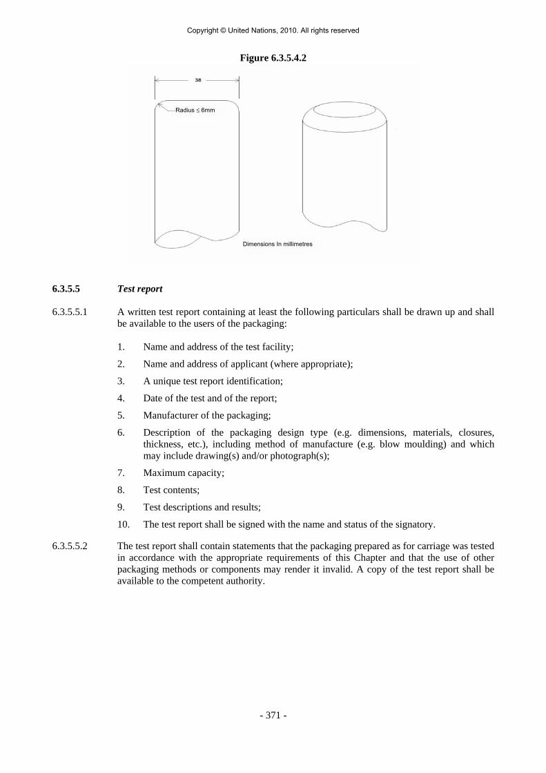
- 371 -
Figure 6.3.5.4.2
Radius ≤ 6mm
Dimensions In millimetres
6.3.5.5 Test report 6.3.5.5.1 A written test report containing at least the following particulars shall be drawn up and shall
be available to the users of the packaging: 1. Name and address of the test facility;
2. Name and address of applicant (where appropriate);
3. A unique test report identification;
4. Date of the test and of the report;
5. Manufacturer of the packaging;
6. Description of the packaging design type (e.g. dimensions, materials, closures, thickness, etc.), including method of manufacture (e.g. blow moulding) and which may include drawing(s) and/or photograph(s);
7. Maximum capacity;
8. Test contents;
9. Test descriptions and results;
10. The test report shall be signed with the name and status of the signatory.
6.3.5.5.2 The test report shall contain statements that the packaging prepared as for carriage was tested in accordance with the appropriate requirements of this Chapter and that the use of other packaging methods or components may render it invalid. A copy of the test report shall be available to the competent authority.
Copyright © United Nations, 2010. All rights reserved

Copyright © United Nations, 2010. All rights reserved

- 373 -
CHAPTER 6.4
REQUIREMENTS FOR THE CONSTRUCTION, TESTING AND APPROVAL OF PACKAGES AND MATERIAL OF CLASS 7
6.4.1 (Reserved) 6.4.2 General requirements 6.4.2.1 The package shall be so designed in relation to its mass, volume and shape that it can be
easily and safely carried. In addition, the package shall be so designed that it can be properly secured in or on the vehicle during carriage.
6.4.2.2 The design shall be such that any lifting attachments on the package will not fail when used
in the intended manner and that, if failure of the attachments should occur, the ability of the package to meet other requirements of this Annex would not be impaired. The design shall take account of appropriate safety factors to cover snatch lifting.
6.4.2.3 Attachments and any other features on the outer surface of the package which could be used
to lift it shall be designed either to support its mass in accordance with the requirements of 6.4.2.2 or shall be removable or otherwise rendered incapable of being used during carriage.
6.4.2.4 As far as practicable, the packaging shall be so designed and finished that the external
surfaces are free from protruding features and can be easily decontaminated. 6.4.2.5 As far as practicable, the outer layer of the package shall be so designed as to prevent the
collection and the retention of water. 6.4.2.6 Any features added to the package at the time of carriage which are not part of the package
shall not reduce its safety. 6.4.2.7 The package shall be capable of withstanding the effects of any acceleration, vibration or
vibration resonance which may arise under routine conditions of carriage without any deterioration in the effectiveness of the closing devices on the various receptacles or in the integrity of the package as a whole. In particular, nuts, bolts and other securing devices shall be so designed as to prevent them from becoming loose or being released unintentionally, even after repeated use.
6.4.2.8 The materials of the packaging and any components or structures shall be physically and
chemically compatible with each other and with the radioactive contents. Account shall be taken of their behaviour under irradiation.
6.4.2.9 All valves through which the radioactive contents could escape shall be protected against
unauthorized operation. 6.4.2.10 The design of the package shall take into account ambient temperatures and pressures that
are likely to be encountered in routine conditions of carriage. 6.4.2.11 For radioactive material having other dangerous properties the package design shall take into
account those properties; see 2.1.3.5.3 and 4.1.9.1.5.
Copyright © United Nations, 2010. All rights reserved

- 374 -
6.4.2.12 Manufacturers and subsequent distributors of packagings shall provide information regarding procedures to be followed and a description of the types and dimensions of closures (including required gaskets) and any other components needed to ensure that packages as presented for carriage are capable of passing the applicable performance tests of this Chapter.
6.4.3 (Reserved) 6.4.4 Requirements for excepted packages An excepted package shall be designed to meet the requirements specified in 6.4.2. 6.4.5 Requirements for Industrial packages 6.4.5.1 Types IP-1, IP-2, and IP-3 packages shall meet the requirements specified in 6.4.2 and
6.4.7.2. 6.4.5.2 A Type IP-2 package shall, if it were subjected to the tests specified in 6.4.15.4 and 6.4.15.5,
prevent: (a) Loss or dispersal of the radioactive contents; and (b) More than a 20% increase in the maximum radiation level at any external surface of
the package. 6.4.5.3 A Type IP-3 package shall meet all the requirements specified in 6.4.7.2 to 6.4.7.15. 6.4.5.4 Alternative requirements for Types IP-2 and IP-3 packages 6.4.5.4.1 Packages may be used as Type IP-2 package provided that: (a) They satisfy the requirements of 6.4.5.1; (b) They are designed to satisfy the requirements prescribed for packing group I or II in
Chapter 6.1; and (c) When subjected to the tests required for packing groups I or II in Chapter 6.1, they
would prevent:
(i) Loss or dispersal of the radioactive contents; and
(ii) More than a 20% increase in the maximum radiation level at any external surface of the package.
6.4.5.4.2 Portable tanks may also be used as Types IP-2 or IP-3 packages, provided that: (a) They satisfy the requirements of 6.4.5.1; (b) They are designed to satisfy the requirements prescribed in Chapter 6.7 and are
capable of withstanding a test pressure of 265 kPa; and (c) They are designed so that any additional shielding which is provided shall be capable
of withstanding the static and dynamic stresses resulting from handling and routine conditions of carriage and of preventing more than a 20% increase in the maximum radiation level at any external surface of the portable tanks.
Copyright © United Nations, 2010. All rights reserved

- 375 -
6.4.5.4.3 Tanks, other than portable tanks, may also be used as Types IP-2 or IP-3 packages for carrying LSA-I and LSA-II liquids and gases as prescribed in Table 4.1.9.2.4, provided that:
(a) They satisfy the requirements of 6.4.5.1; (b) They are designed to satisfy the requirements prescribed in Chapter 6.8; and (c) They are designed so that any additional shielding which is provided shall be capable
of withstanding the static and dynamic stresses resulting from handling and routine conditions of carriage and of preventing more than a 20% increase in the maximum radiation level at any external surface of the tanks.
6.4.5.4.4 Containers with the characteristics of a permanent enclosure may also be used as Types IP-2
or IP-3 packages, provided that:
(a) The radioactive contents are restricted to solid materials; (b) They satisfy the requirements of 6.4.5.1; and (c) They are designed to conform to ISO 1496-1:1990: "Series 1 Containers -
Specifications and Testing - Part 1: General Cargo Containers" and subsequent amendments 1:1993, 2:1998, 3:2005, 4:2006 and 5:2006, excluding dimensions and ratings. They shall be designed such that if subjected to the tests prescribed in that document and the accelerations occurring during routine conditions of carriage they would prevent:
(i) loss or dispersal of the radioactive contents; and
(ii) more than a 20% increase in the maximum radiation level at any external surface of the containers.
6.4.5.4.5 Metal intermediate bulk containers may also be used as Types IP-2 or IP-3 packages
provided that:
(a) They satisfy the requirements of 6.4.5.1; and (b) They are designed to satisfy the requirements prescribed in Chapter 6.5 for packing
group I or II, and if they were subjected to the tests prescribed in that Chapter, but with the drop test conducted in the most damaging orientation, they would prevent:
(i) loss or dispersal of the radioactive contents; and
(ii) more than a 20% increase in the maximum radiation level at any external surface of the intermediate bulk container.
6.4.6 Requirements for packages containing uranium hexafluoride 6.4.6.1 Packages designed to contain uranium hexafluoride shall meet the requirements prescribed
elsewhere in ADR which pertain to the radioactive and fissile properties of the material. Except as allowed in 6.4.6.4, uranium hexafluoride in quantities of 0.1 kg or more shall also be packaged and carried in accordance with the provisions of ISO 7195:2005 "Nuclear Energy – Packaging of uranium hexafluoride (UF6) for transport", and the requirements of 6.4.6.2 and 6.4.6.3.
6.4.6.2 Each package designed to contain 0.1 kg or more of uranium hexafluoride shall be designed
so that it would meet the following requirements:
Copyright © United Nations, 2010. All rights reserved

- 376 -
(a) Withstand without leakage and without unacceptable stress, as specified in ISO 7195:2005, the structural test as specified in 6.4.21.5;
(b) Withstand without loss or dispersal of the uranium hexafluoride the free drop test specified in 6.4.15.4; and
(c) Withstand without rupture of the containment system the thermal test specified in 6.4.17.3.
6.4.6.3 Packages designed to contain 0.1 kg or more of uranium hexafluoride shall not be provided
with pressure relief devices. 6.4.6.4 Subject to the approval of the competent authority, packages designed to contain 0.1 kg or
more of uranium hexafluoride may be carried if:
(a) The packages are designed to international or national standards other than ISO 7195:2005 provided an equivalent level of safety is maintained;
(b) The packages are designed to withstand without leakage and without unacceptable
stress a test pressure of less than 2.76 MPa as specified in 6.4.21.5; or (c) For packages designed to contain 9 000 kg or more of uranium hexafluoride, the
packages do not meet the requirement of 6.4.6.2 (c). In all other respects the requirements specified in 6.4.6.1 to 6.4.6.3 shall be satisfied.
6.4.7 Requirements for Type A packages 6.4.7.1 Type A packages shall be designed to meet the general requirements of 6.4.2 and of 6.4.7.2
to 6.4.7.17. 6.4.7.2 The smallest overall external dimension of the package shall not be less than 10 cm. 6.4.7.3 The outside of the package shall incorporate a feature such as a seal, which is not readily
breakable and which, while intact, will be evidence that it has not been opened. 6.4.7.4 Any tie-down attachments on the package shall be so designed that, under normal and
accident conditions of carriage, the forces in those attachments shall not impair the ability of the package to meet the requirements of ADR.
6.4.7.5 The design of the package shall take into account temperatures ranging from -40°C to +70°C
for the components of the packaging. Attention shall be given to freezing temperatures for liquids and to the potential degradation of packaging materials within the given temperature range.
6.4.7.6 The design and manufacturing techniques shall be in accordance with national or
international standards, or other requirements, acceptable to the competent authority. 6.4.7.7 The design shall include a containment system securely closed by a positive fastening device
which cannot be opened unintentionally or by a pressure which may arise within the package.
6.4.7.8 Special form radioactive material may be considered as a component of the containment
system.
Copyright © United Nations, 2010. All rights reserved

- 377 -
6.4.7.9 If the containment system forms a separate unit of the package, it shall be capable of being securely closed by a positive fastening device which is independent of any other part of the packaging.
6.4.7.10 The design of any component of the containment system shall take into account, where applicable, the radiolytic decomposition of liquids and other vulnerable materials and the generation of gas by chemical reaction and radiolysis.
6.4.7.11 The containment system shall retain its radioactive contents under a reduction of ambient
pressure to 60 kPa. 6.4.7.12 All valves, other than pressure relief valves, shall be provided with an enclosure to retain any
leakage from the valve. 6.4.7.13 A radiation shield which encloses a component of the package specified as a part of the
containment system shall be so designed as to prevent the unintentional release of that component from the shield. Where the radiation shield and such component within it form a separate unit, the radiation shield shall be capable of being securely closed by a positive fastening device which is independent of any other packaging structure.
6.4.7.14 A package shall be so designed that if it were subjected to the tests specified in 6.4.15, it
would prevent:
(a) Loss or dispersal of the radioactive contents; and (b) More than a 20% increase in the maximum radiation level at any external surface of
the package. 6.4.7.15 The design of a package intended for liquid radioactive material shall make provision for
ullage to accommodate variations in the temperature of the contents, dynamic effects and filling dynamics.
Type A packages to contain liquids 6.4.7.16 A Type A package designed to contain liquid radioactive material shall, in addition:
(a) Be adequate to meet the conditions specified in 6.4.7.14 (a) above if the package is subjected to the tests specified in 6.4.16; and
(b) Either
(i) be provided with sufficient absorbent material to absorb twice the volume of the liquid contents. Such absorbent material shall be suitably positioned so as to contact the liquid in the event of leakage; or
(ii) be provided with a containment system composed of primary inner and
secondary outer containment components designed to enclose the liquid contents completely and ensure their retention, within the secondary outer containment components, even if the primary inner components leak.
Type A packages to contain gas 6.4.7.17 A package designed for gases shall prevent loss or dispersal of the radioactive contents if the
package were subjected to the tests specified in 6.4.16. A Type A package designed for tritium gas or for noble gases shall be excepted from this requirement.
Copyright © United Nations, 2010. All rights reserved

- 378 -
6.4.8 Requirements for Type B(U) packages 6.4.8.1 Type B(U) packages shall be designed to meet the requirements specified in 6.4.2, and of
6.4.7.2 to 6.4.7.15, except as specified in 6.4.7.14 (a), and, in addition, the requirements specified in 6.4.8.2 to 6.4.8.15.
6.4.8.2 A package shall be so designed that, under the ambient conditions specified in 6.4.8.5
and 6.4.8.6 heat generated within the package by the radioactive contents shall not, under normal conditions of carriage, as demonstrated by the tests in 6.4.15, adversely affect the package in such a way that it would fail to meet the applicable requirements for containment and shielding if left unattended for a period of one week. Particular attention shall be paid to the effects of heat, which may:
(a) Alter the arrangement, the geometrical form or the physical state of the radioactive
contents or, if the radioactive material is enclosed in a can or receptacle (for example, clad fuel elements), cause the can, receptacle or radioactive material to deform or melt; or
(b) Lessen the efficiency of the packaging through differential thermal expansion or
cracking or melting of the radiation shielding material; or (c) In combination with moisture, accelerate corrosion.
6.4.8.3 A package shall be so designed that, under the ambient condition specified in 6.4.8.5 and in
the absence of insolation, the temperature of the accessible surfaces of a package shall not exceed 50 °C, unless the package is carried under exclusive use.
6.4.8.4 The maximum temperature of any surface readily accessible during carriage of a package
under exclusive use shall not exceed 85 °C in the absence of insolation under the ambient conditions specified in 6.4.8.5. Account may be taken of barriers or screens intended to give protection to persons without the need for the barriers or screens being subject to any test.
6.4.8.5 The ambient temperature shall be assumed to be 38 °C. 6.4.8.6 The solar insolation conditions shall be assumed to be as specified in Table 6.4.8.6.
Table 6.4.8.6: Insolation data
Case Form and location of surface Insolation for 12 hours per day (W/m2)
1 Flat surfaces carried horizontally-downward facing 0
2 Flat surfaces carried horizontally-upward facing 800 3 Surfaces carried vertically 200a 4 Other downward facing (not horizontal) surfaces 200a 5 All other surfaces 400a
a Alternatively, a sine function may be used, with an absorption coefficient adopted and the effects of possible reflection from neighbouring objects neglected.
6.4.8.7 A package which includes thermal protection for the purpose of satisfying the requirements
of the thermal test specified in 6.4.17.3 shall be so designed that such protection will remain effective if the package is subjected to the tests specified in 6.4.15 and 6.4.17.2 (a) and (b) or 6.4.17.2 (b) and (c), as appropriate. Any such protection on the exterior of the package shall not be rendered ineffective by ripping, cutting, skidding, abrasion or rough handling.
Copyright © United Nations, 2010. All rights reserved

- 379 -
6.4.8.8 A package shall be so designed that, if it were subjected to:
(a) The tests specified in 6.4.15, it would restrict the loss of radioactive contents to not more than 10-6 A2 per hour; and
(b) The tests specified in 6.4.17.1, 6.4.17.2 (b), 6.4.17.3, and 6.4.17.4 and the tests in
(i) 6.4.17.2 (c), when the package has a mass not greater than 500 kg, an overall
density not greater than 1 000 kg/m3 based on the external dimensions, and radioactive contents greater than 1 000 A2 not as special form radioactive material, or
(ii) 6.4.17.2 (a), for all other packages,
it would meet the following requirements:
- retain sufficient shielding to ensure that the radiation level at 1 m from the surface of the package would not exceed 10 mSv/h with the maximum radioactive contents which the package is designed to contain; and
- restrict the accumulated loss of radioactive contents in a period of one week to not
more than 10 A2 for krypton-85 and not more than A2 for all other radionuclides. Where mixtures of different radionuclides are present, the provisions of 2.2.7.2.2.4 to
2.2.7.2.2.6 shall apply except that for krypton-85 an effective A2(i) value equal to 10 A2 may be used. For case (a) above, the assessment shall take into account the external contamination limits of 4.1.9.1.2.
6.4.8.9 A package for radioactive contents with activity greater than 105 A2 shall be so designed that
if it were subjected to the enhanced water immersion test specified in 6.4.18, there would be no rupture of the containment system.
6.4.8.10 Compliance with the permitted activity release limits shall depend neither upon filters nor
upon a mechanical cooling system. 6.4.8.11 A package shall not include a pressure relief system from the containment system which
would allow the release of radioactive material to the environment under the conditions of the tests specified in 6.4.15 and 6.4.17.
6.4.8.12 A package shall be so designed that if it were at the maximum normal operating pressure and
it were subjected to the tests specified in 6.4.15 and 6.4.17, the level of strains in the containment system would not attain values which would adversely affect the package in such a way that it would fail to meet the applicable requirements.
6.4.8.13 A package shall not have a maximum normal operating pressure in excess of a gauge
pressure of 700 kPa. 6.4.8.14 A package containing low dispersible radioactive material shall be so designed that any
features added to the low dispersible radioactive material that are not part of it, or any internal components of the packaging shall not adversely affect the performance of the low dispersible radioactive material.
6.4.8.15 A package shall be designed for an ambient temperature range from -40 °C to +38 °C.
Copyright © United Nations, 2010. All rights reserved

- 380 -
6.4.9 Requirements for Type B(M) packages 6.4.9.1 Type B(M) packages shall meet the requirements for Type B(U) packages specified
in 6.4.8.1, except that for packages to be carried solely within a specified country or solely between specified countries, conditions other than those given in 6.4.7.5, 6.4.8.5, 6.4.8.6, and 6.4.8.9 to 6.4.8.15 above may be assumed with the approval of the competent authorities of these countries. Notwithstanding, the requirements for Type B(U) packages specified in 6.4.8.9 to 6.4.8.15 shall be met as far as practicable.
6.4.9.2 Intermittent venting of Type B(M) packages may be permitted during carriage, provided that
the operational controls for venting are acceptable to the relevant competent authorities. 6.4.10 Requirements for Type C packages
6.4.10.1 Type C packages shall be designed to meet the requirements specified in 6.4.2 and of 6.4.7.2
to 6.4.7.15, except as specified in 6.4.7.14 (a), and of the requirements specified in 6.4.8.2 to 6.4.8.6, 6.4.8.10 to 6.4.8.15, and, in addition, of 6.4.10.2 to 6.4.10.4.
6.4.10.2 A package shall be capable of meeting the assessment criteria prescribed for tests in
6.4.8.8 (b) and 6.4.8.12 after burial in an environment defined by a thermal conductivity of 0.33 W.m-1.K-1 and a temperature of 38 °C in the steady state. Initial conditions for the assessment shall assume that any thermal insulation of the package remains intact, the package is at the maximum normal operating pressure and the ambient temperature is 38 °C.
6.4.10.3 A package shall be so designed that, if it were at the maximum normal operating pressure
and subjected to:
(a) The tests specified in 6.4.15, it would restrict the loss of radioactive contents to not more than 10-6 A2 per hour; and
(b) The test sequences in 6.4.20.1, it would meet the following requirements:
(i) retain sufficient shielding to ensure that the radiation level at 1 m from the surface of the package would not exceed 10 mSv/h with the maximum radioactive contents which the package is designed to contain; and
(ii) restrict the accumulated loss of radioactive contents in a period of 1 week to not
more than 10 A2 for krypton-85 and not more than A2 for all other radionuclides.
Where mixtures of different radionuclides are present, the provisions of 2.2.7.2.2.4 to 2.2.7.2.2.6 shall apply except that for krypton-85 an effective A2(i) value equal to 10 A2 may be used. For case (a) above, the assessment shall take into account the external contamination limits of 4.1.9.1.2.
6.4.10.4 A package shall be so designed that there will be no rupture of the containment system
following performance of the enhanced water immersion test specified in 6.4.18.
Copyright © United Nations, 2010. All rights reserved

- 381 -
6.4.11 Requirements for packages containing fissile material 6.4.11.1 Fissile material shall be carried so as to:
(a) Maintain sub-criticality during normal and accident conditions of carriage; in particular, the following contingencies shall be considered:
(i) water leaking into or out of packages; (ii) the loss of efficiency of built-in neutron absorbers or moderators; (iii) rearrangement of the contents either within the package or as a result of loss
from the package; (iv) reduction of spaces within or between packages; (v) packages becoming immersed in water or buried in snow; and
(vi) temperature changes; and
(b) Meet the requirements:
(i) of 6.4.7.2 for packages containing fissile material; (ii) prescribed elsewhere in ADR which pertain to the radioactive properties of the
material; and (iii) specified in 6.4.11.3 to 6.4.11.12, unless excepted by 6.4.11.2.
6.4.11.2 Fissile material meeting one of the provisions (a) to (d) of 2.2.7.2.3.5 is excepted from the
requirement to be carried in packages that comply with 6.4.11.3 to 6.4.11.12 as well as the other requirements of ADR that apply to fissile material. Only one type of exception is allowed per consignment.
6.4.11.3 Where the chemical or physical form, isotopic composition, mass or concentration, moderation ratio or density, or geometric configuration is not known, the assessments of 6.4.11.7 to 6.4.11.12 shall be performed assuming that each parameter that is not known has the value which gives the maximum neutron multiplication consistent with the known conditions and parameters in these assessments.
6.4.11.4 For irradiated nuclear fuel the assessments of 6.4.11.7 to 6.4.11.12 shall be based on an
isotopic composition demonstrated to provide:
(a) The maximum neutron multiplication during the irradiation history; or (b) A conservative estimate of the neutron multiplication for the package assessments.
After irradiation but prior to shipment, a measurement shall be performed to confirm the conservatism of the isotopic composition.
6.4.11.5 The package, after being subjected to the tests specified in 6.4.15, shall:
(a) Preserve the minimum overall outside dimensions of the package to at least 10 cm;
and (b) Prevent the entry of a 10 cm cube.
Copyright © United Nations, 2010. All rights reserved

- 382 -
6.4.11.6 The package shall be designed for an ambient temperature range of -40°C to + 38°C unless the competent authority specifies otherwise in the certificate of approval for the package design.
6.4.11.7 For a package in isolation, it shall be assumed that water can leak into or out of all void
spaces of the package, including those within the containment system. However, if the design incorporates special features to prevent such leakage of water into or out of certain void spaces, even as a result of error, absence of leakage may be assumed in respect of those void spaces. Special features shall include the following:
(a) Multiple high standard water barriers, not less than two of which would remain
watertight if the package were subject to the tests prescribed in 6.4.11.12 (b), a high degree of quality control in the manufacture, maintenance and repair of packagings and tests to demonstrate the closure of each package before each shipment; or
(b) For packages containing uranium hexafluoride only, with maximum enrichment of
5 mass percent uranium-235:
(i) packages where, following the tests prescribed in 6.4.11.12 (b), there is no physical contact between the valve and any other component of the packaging other than at its original point of attachment and where, in addition, following the test prescribed in 6.4.17.3 the valves remain leaktight; and
(ii) a high degree of quality control in the manufacture, maintenance and repair of
packagings coupled with tests to demonstrate closure of each package before each shipment.
6.4.11.8 It shall be assumed that the confinement system shall be closely reflected by at least 20 cm
of water or such greater reflection as may additionally be provided by the surrounding material of the packaging. However, when it can be demonstrated that the confinement system remains within the packaging following the tests prescribed in 6.4.11.12 (b), close reflection of the package by at least 20 cm of water may be assumed in 6.4.11.9 (c).
6.4.11.9 The package shall be subcritical under the conditions of 6.4.11.7 and 6.4.11.8 with the
package conditions that result in the maximum neutron multiplication consistent with:
(a) Routine conditions of carriage (incident free); (b) The tests specified in 6.4.11.11 (b); (c) The tests specified in 6.4.11.12 (b).
6.4.11.10 (Reserved) 6.4.11.11 For normal conditions of carriage a number "N" shall be derived, such that five times "N"
packages shall be subcritical for the arrangement and package conditions that provide the maximum neutron multiplication consistent with the following:
(a) There shall not be anything between the packages, and the package arrangement shall
be reflected on all sides by at least 20 cm of water; and (b) The state of the packages shall be their assessed or demonstrated condition if they had
been subjected to the tests specified in 6.4.15.
Copyright © United Nations, 2010. All rights reserved

- 383 -
6.4.11.12 For accident conditions of carriage a number "N" shall be derived, such that two times "N" packages shall be subcritical for the arrangement and package conditions that provide the maximum neutron multiplication consistent with the following:
(a) Hydrogenous moderation between packages, and the package arrangement reflected
on all sides by at least 20 cm of water; and
(b) The tests specified in 6.4.15 followed by whichever of the following is the more limiting:
(i) the tests specified in 6.4.17.2 (b) and, either 6.4.17.2 (c) for packages having a
mass not greater than 500 kg and an overall density not greater than 1 000 kg/m3 based on the external dimensions, or 6.4.17.2 (a) for all other packages; followed by the test specified in 6.4.17.3 and completed by the tests specified in 6.4.19.1 to 6.4.19.3; or
(ii) the test specified in 6.4.17.4; and
(c) Where any part of the fissile material escapes from the containment system following
the tests specified in 6.4.11.12 (b), it shall be assumed that fissile material escapes from each package in the array and all of the fissile material shall be arranged in the configuration and moderation that results in the maximum neutron multiplication with close reflection by at least 20 cm of water.
6.4.11.13 The criticality safety index (CSI) for packages containing fissile material shall be obtained
by dividing the number 50 by the smaller of the two values of N derived in 6.4.11.11 and 6.4.11.12 (i.e. CSI = 50/N). The value of the criticality safety index may be zero, provided that an unlimited number of packages is subcritical (i.e. N is effectively equal to infinity in both cases).
6.4.12 Test procedures and demonstration of compliance 6.4.12.1 Demonstration of compliance with the performance standards required in 2.2.7.2.3.1.3,
2.2.7.2.3.1.4, 2.2.7.2.3.3.1, 2.2.7.2.3.3.2, 2.2.7.2.3.4.1, 2.2.7.2.3.4.2, and 6.4.2 to 6.4.11 must be accomplished by any of the methods listed below or by a combination thereof:
(a) Performance of tests with specimens representing LSA-III material, or special form
radioactive material, or low dispersible radioactive material or with prototypes or samples of the packaging, where the contents of the specimen or the packaging for the tests shall simulate as closely as practicable the expected range of radioactive contents and the specimen or packaging to be tested shall be prepared as presented for carriage;
(b) Reference to previous satisfactory demonstrations of a sufficiently similar nature; (c) Performance of tests with models of appropriate scale incorporating those features
which are significant with respect to the item under investigation when engineering experience has shown results of such tests to be suitable for design purposes. When a scale model is used, the need for adjusting certain test parameters, such as penetrator diameter or compressive load, shall be taken into account;
(d) Calculation, or reasoned argument, when the calculation procedures and parameters
are generally agreed to be reliable or conservative.
Copyright © United Nations, 2010. All rights reserved

- 384 -
6.4.12.2 After the specimen, prototype or sample has been subjected to the tests, appropriate methods of assessment shall be used to assure that the requirements for the test procedures have been fulfilled in compliance with the performance and acceptance standards prescribed in 2.2.7.2.3.1.3, 2.2.7.2.3.1.4, 2.2.7.2.3.3.1, 2.2.7.2.3.3.2, 2.2.7.2.3.4.1, 2.2.7.2.3.4.2, and 6.4.2 to 6.4.11.
6.4.12.3 All specimens shall be inspected before testing in order to identify and record faults or
damage including the following:
(a) Divergence from the design; (b) Defects in manufacture; (c) Corrosion or other deterioration; and (d) Distortion of features.
The containment system of the package shall be clearly specified. The external features of the specimen shall be clearly identified so that reference may be made simply and clearly to any part of such specimen.
6.4.13 Testing the integrity of the containment system and shielding and evaluating criticality
safety After each of the applicable tests specified in 6.4.15 to 6.4.21:
(a) Faults and damage shall be identified and recorded; (b) It shall be determined whether the integrity of the containment system and shielding
has been retained to the extent required in 6.4.2 to 6.4.11 for the package under test; and
(c) For packages containing fissile material, it shall be determined whether the
assumptions and conditions used in the assessments required by 6.4.11.1 to 6.4.11.13 for one or more packages are valid.
6.4.14 Target for drop tests The target for the drop tests specified in 2.2.7.2.3.3.5 (a), 6.4.15.4, 6.4.16 (a), 6.4.17.2 and
6.4.20.2 shall be a flat, horizontal surface of such a character that any increase in its resistance to displacement or deformation upon impact by the specimen would not significantly increase the damage to the specimen.
6.4.15 Tests for demonstrating ability to withstand normal conditions of carriage 6.4.15.1 The tests are: the water spray test, the free drop test, the stacking test and the penetration test.
Specimens of the package shall be subjected to the free drop test, the stacking test and the penetration test, preceded in each case by the water spray test. One specimen may be used for all the tests, provided that the requirements of 6.4.15.2 are fulfilled.
6.4.15.2 The time interval between the conclusion of the water spray test and the succeeding test shall
be such that the water has soaked in to the maximum extent, without appreciable drying of the exterior of the specimen. In the absence of any evidence to the contrary, this interval
Copyright © United Nations, 2010. All rights reserved

- 385 -
shall be taken to be two hours if the water spray is applied from four directions simultaneously. No time interval shall elapse, however, if the water spray is applied from each of the four directions consecutively.
6.4.15.3 Water spray test: The specimen shall be subjected to a water spray test that simulates
exposure to rainfall of approximately 5 cm per hour for at least one hour.
6.4.15.4 Free drop test: The specimen shall drop onto the target so as to suffer maximum damage in respect of the safety features to be tested.
(a) The height of drop measured from the lowest point of the specimen to the upper
surface of the target shall be not less than the distance specified in Table 6.4.15.4 for the applicable mass. The target shall be as defined in 6.4.14;
(b) For rectangular fibreboard or wood packages not exceeding a mass of 50 kg, a
separate specimen shall be subjected to a free drop onto each corner from a height of 0.3 m;
(c) For cylindrical fibreboard packages not exceeding a mass of 100 kg, a separate
specimen shall be subjected to a free drop onto each of the quarters of each rim from a height of 0.3 m.
Table 6.4.15.4: Free drop distance for testing packages to normal conditions of
carriage
Package mass (kg) Free drop distance (m) Package mass < 5 000 1.2
5 000 ≤ Package mass < 10 000 0.9
10 000 ≤ Package mass < 15 000 0.6
15 000 ≤ Package mass 0.3
6.4.15.5 Stacking test: Unless the shape of the packaging effectively prevents stacking, the specimen shall be subjected, for a period of 24 h, to a compressive load equal to the greater of the following:
(a) A total weight equal to 5 times the maximum weight of the package; and (b) The equivalent of 13 kPa multiplied by the vertically projected area of the package.
The load shall be applied uniformly to two opposite sides of the specimen, one of which
shall be the base on which the package would typically rest. 6.4.15.6 Penetration test: The specimen shall be placed on a rigid, flat, horizontal surface which will
not move significantly while the test is being carried out.
(a) A bar of 3.2 cm in diameter with a hemispherical end and a mass of 6 kg shall be dropped and directed to fall, with its longitudinal axis vertical, onto the centre of the weakest part of the specimen, so that, if it penetrates sufficiently far, it will hit the containment system. The bar shall not be significantly deformed by the test performance;
(b) The height of drop of the bar measured from its lower end to the intended point of
impact on the upper surface of the specimen shall be 1 m.
Copyright © United Nations, 2010. All rights reserved

- 386 -
6.4.16 Additional tests for Type A packages designed for liquids and gases A specimen or separate specimens shall be subjected to each of the following tests unless it
can be demonstrated that one test is more severe for the specimen in question than the other, in which case one specimen shall be subjected to the more severe test.
(a) Free drop test: The specimen shall drop onto the target so as to suffer the maximum
damage in respect of containment. The height of the drop measured from the lowest part of the specimen to the upper surface of the target shall be 9 m. The target shall be as defined in 6.4.14;
(b) Penetration test: The specimen shall be subjected to the test specified in 6.4.15.6
except that the height of drop shall be increased to 1.7 m from the 1 m specified in 6.4.15.6 (b).
6.4.17 Tests for demonstrating ability to withstand accident conditions in carriage 6.4.17.1 The specimen shall be subjected to the cumulative effects of the tests specified in 6.4.17.2
and 6.4.17.3, in that order. Following these tests, either this specimen or a separate specimen shall be subjected to the effect(s) of the water immersion test(s) as specified in 6.4.17.4 and, if applicable, 6.4.18.
6.4.17.2 Mechanical test: The mechanical test consists of three different drop tests. Each specimen
shall be subjected to the applicable drops as specified in 6.4.8.8 or 6.4.11.12. The order in which the specimen is subjected to the drops shall be such that, on completion of the mechanical test, the specimen shall have suffered such damage as will lead to the maximum damage in the thermal test which follows.
(a) For drop I, the specimen shall drop onto the target so as to suffer the maximum damage, and the height of the drop measured from the lowest point of the specimen to the upper surface of the target shall be 9 m. The target shall be as defined in 6.4.14;
(b) For drop II, the specimen shall drop so as to suffer the maximum damage onto a bar rigidly mounted perpendicularly on the target. The height of the drop measured from the intended point of impact of the specimen to the upper surface of the bar shall be 1 m. The bar shall be of solid mild steel of circular section, (15.0 cm ± 0.5 cm) in diameter and 20 cm long unless a longer bar would cause greater damage, in which case a bar of sufficient length to cause maximum damage shall be used. The upper end of the bar shall be flat and horizontal with its edge rounded off to a radius of not more than 6 mm. The target on which the bar is mounted shall be as described in 6.4.14;
(c) For drop III, the specimen shall be subjected to a dynamic crush test by positioning the specimen on the target so as to suffer maximum damage by the drop of a 500 kg mass from 9 m onto the specimen. The mass shall consist of a solid mild steel plate 1 m by 1 m and shall fall in a horizontal attitude. The height of the drop shall be measured from the underside of the plate to the highest point of the specimen. The target on which the specimen rests shall be as defined in 6.4.14.
6.4.17.3 Thermal test: The specimen shall be in thermal equilibrium under conditions of an ambient
temperature of 38 °C, subject to the solar insolation conditions specified in Table 6.4.8.6 and subject to the design maximum rate of internal heat generation within the package from the radioactive contents. Alternatively, any of these parameters are allowed to have different values prior to and during the test, providing due account is taken of them in the subsequent assessment of package response.
The thermal test shall then consist of:
Copyright © United Nations, 2010. All rights reserved
- 387 -
(a) Exposure of a specimen for a period of 30 minutes to a thermal environment which provides a heat flux at least equivalent to that of a hydrocarbon fuel/air fire in sufficiently quiescent ambient conditions to give a minimum average flame emissivity coefficient of 0.9 and an average temperature of at least 800 °C, fully engulfing the specimen, with a surface absorptivity coefficient of 0.8 or that value which the package may be demonstrated to possess if exposed to the fire specified, followed by;
(b) Exposure of the specimen to an ambient temperature of 38 °C, subject to the solar insolation conditions specified in Table 6.4.8.6 and subject to the design maximum rate of internal heat generation within the package by the radioactive contents for a sufficient period to ensure that temperatures in the specimen are everywhere decreasing and/or are approaching initial steady state conditions. Alternatively, any of these parameters are allowed to have different values following cessation of heating, providing due account is taken of them in the subsequent assessment of package response.
During and following the test the specimen shall not be artificially cooled and any combustion of materials of the specimen shall be permitted to proceed naturally.
6.4.17.4 Water immersion test: The specimen shall be immersed under a head of water of at least
15 m for a period of not less than eight hours in the attitude which will lead to maximum damage. For demonstration purposes, an external gauge pressure of at least 150 kPa shall be considered to meet these conditions.
6.4.18 Enhanced water immersion test for Type B(U) and Type B(M) packages containing
more than 105 A2 and Type C packages Enhanced water immersion test: The specimen shall be immersed under a head of water of at
least 200 m for a period of not less than one hour. For demonstration purposes, an external gauge pressure of at least 2 MPa shall be considered to meet these conditions.
6.4.19 Water leakage test for packages containing fissile material 6.4.19.1 Packages for which water in-leakage or out-leakage to the extent which results in greatest
reactivity has been assumed for purposes of assessment under 6.4.11.7 to 6.4.11.12 shall be excepted from the test.
6.4.19.2 Before the specimen is subjected to the water leakage test specified below, it shall be
subjected to the tests in 6.4.17.2 (b), and either 6.4.17.2 (a) or (c) as required by 6.4.11.12, and the test specified in 6.4.17.3.
6.4.19.3 The specimen shall be immersed under a head of water of at least 0.9 m for a period of not
less than 8 hours and in the attitude for which maximum leakage is expected. 6.4.20 Tests for Type C packages 6.4.20.1 Specimens shall be subjected to the effects of each of the following test sequences in the
orders specified: (a) The tests specified in 6.4.17.2 (a), 6.4.17.2 (c), 6.4.20.2 and 6.4.20.3; and (b) The test specified in 6.4.20.4.
Copyright © United Nations, 2010. All rights reserved

- 388 -
Separate specimens are allowed to be used for each of the sequences (a) and (b). 6.4.20.2 Puncture/tearing test: The specimen shall be subjected to the damaging effects of a solid
probe made of mild steel. The orientation of the probe to the surface of the specimen shall be as to cause maximum damage at the conclusion of the test sequence specified in 6.4.20.1 (a). (a) The specimen, representing a package having a mass less than 250 kg, shall be placed
on a target and subjected to a probe having a mass of 250 kg falling from a height of 3 m above the intended impact point. For this test the probe shall be a 20 cm diameter cylindrical bar with the striking end forming a frustum of a right circular cone with the following dimensions: 30 cm height and 2.5 cm in diameter at the top with its edge rounded off to a radius of not more than 6 mm. The target on which the specimen is placed shall be as specified in 6.4.14;
(b) For packages having a mass of 250 kg or more, the base of the probe shall be placed
on a target and the specimen dropped onto the probe. The height of the drop, measured from the point of impact with the specimen to the upper surface of the probe shall be 3 m. For this test the probe shall have the same properties and dimensions as specified in (a) above, except that the length and mass of the probe shall be such as to incur maximum damage to the specimen. The target on which the base of the probe is placed shall be as specified in 6.4.14.
6.4.20.3 Enhanced thermal test: The conditions for this test shall be as specified in 6.4.17.3, except
that the exposure to the thermal environment shall be for a period of 60 minutes. 6.4.20.4 Impact test: The specimen shall be subject to an impact on a target at a velocity of not less
than 90 m/s, at such an orientation as to suffer maximum damage. The target shall be as defined in 6.4.14, except that the target surface may be at any orientation as long as the surface is normal to the specimen path.
6.4.21 Inspections for packagings designed to contain 0.1 kg or more of uranium hexafluoride 6.4.21.1 Every manufactured packaging and its service and structural equipment shall, either jointly
or separately, undergo an inspection initially before being put into service and periodically thereafter. These inspections shall be performed and certified by agreement with the competent authority.
6.4.21.2 The initial inspection shall consist of a check of the design characteristics, a structural test, a
leakproofness test, a water capacity test and a check of satisfactory operation of the service equipment.
6.4.21.3 The periodic inspections shall consist of a visual examination, a structural test, a
leakproofness test and a check of satisfactory operation of the service equipment. The maximum intervals for periodic inspections shall be five years. Packagings which have not been inspected within this five-year period shall be examined before carriage in accordance with a programme approved by the competent authority. They shall not be refilled before completion of the full programme for periodic inspections.
6.4.21.4 The check of design characteristics shall demonstrate compliance with the design type
specifications and the manufacturing programme. 6.4.21.5 For the initial structural test, packagings designed to contain 0.1 kg or more of uranium
hexafluoride shall be tested hydraulically at an internal pressure of at least 1.38 MPa but, when the test pressure is less than 2.76 MPa, the design shall require multilateral approval.
Copyright © United Nations, 2010. All rights reserved

- 389 -
For retesting packagings, any other equivalent non-destructive testing may be applied subject to multilateral approval.
6.4.21.6 The leakproofness test shall be performed in accordance with a procedure which is capable
of indicating leakages in the containment system with a sensitivity of 0.1 Pa.l/s (10-6 bar.l/s). 6.4.21.7 The water capacity of the packagings shall be established with an accuracy of ± 0.25% at a
reference temperature of 15 °C. The volume shall be stated on the plate described in 6.4.21.8.
6.4.21.8 A plate made of non-corroding metal shall be durably attached to every packaging in a
readily accessible place. The method of attaching the plate must not impair the strength of the packaging. The following particulars, at least, shall be marked on the plate by stamping or by any other equivalent method:
- Approval number;
- Manufacturer's serial number;
- Maximum working pressure (gauge pressure);
- Test pressure (gauge pressure);
- Contents: uranium hexafluoride;
- Capacity in litres;
- Maximum permissible filling mass of uranium hexafluoride;
- Tare mass;
- Date (month, year) of the initial test and the most recent periodic test;
- Stamp of the expert who performed the tests. 6.4.22 Approvals of package designs and materials 6.4.22.1 The approval of designs for packages containing 0.1 kg or more of uranium hexafluoride
requires that:
(a) Each design that meets the requirements of 6.4.6.4 shall require multilateral approval; (b) Each design that meets the requirements of 6.4.6.1 to 6.4.6.3 shall require unilateral
approval by the competent authority of the country of origin of the design, unless multilateral approval is otherwise required by ADR.
6.4.22.2 Each Type B(U) and Type C package design shall require unilateral approval, except that:
(a) A package design for fissile material, which is also subject to 6.4.22.4, 6.4.23.7, and 5.1.5.2.1 shall require multilateral approval; and
(b) A Type B(U) package design for low dispersible radioactive material shall require
multilateral approval.
Copyright © United Nations, 2010. All rights reserved
- 390 -
6.4.22.3 Each Type B(M) package design, including those for fissile material which are also subject to the requirements of 6.4.22.4, 6.4.23.7, and 5.1.5.2.1 and those for low dispersible radioactive material, shall require multilateral approval.
6.4.22.4 Each package design for fissile material which is not excepted according to 6.4.11.2 from the
requirements that apply specifically to packages containing fissile material shall require multilateral approval.
6.4.22.5 The design for special form radioactive material shall require unilateral approval. The design
for low dispersible radioactive material shall require multilateral approval (see also 6.4.23.8). 6.4.22.6 Any design that requires unilateral approval originating in a country Contracting Party
to ADR shall be approved by the competent authority of this country; if the country where the package has been designed is not a Contracting Party to ADR, carriage is possible on condition that:
(a) A certificate has been supplied by this country, proving that the package design
satisfies the technical requirements of ADR, and that this certificate is countersigned by the competent authority of the first country Contracting Party to ADR reached by the consignment;
(b) If no certificate and no existing package design approval by a country Contracting
Party to ADR has been supplied, the package design is approved by the competent authority of the first country Contracting Party to ADR reached by the consignment.
6.4.22.7 For designs approved under the transitional measures see 1.6.6. 6.4.23 Applications and approvals for radioactive material carriage 6.4.23.1 (Reserved) 6.4.23.2 An application for shipment approval shall include:
(a) The period of time, related to the shipment, for which the approval is sought; (b) The actual radioactive contents, the expected modes of carriage, the type of vehicle,
and the probable or proposed route; and
(c) The details of how the precautions and administrative or operational controls, referred to in the package design approval certificates issued under 5.1.5.2.1, are to be put into effect.
6.4.23.3 An application for approval of shipments under special arrangement shall include all the
information necessary to satisfy the competent authority that the overall level of safety in carriage is at least equivalent to that which would be provided if all the applicable requirements of ADR had been met.
The application shall also include:
(a) A statement of the respects in which, and of the reasons why, the shipment cannot be made in full accordance with the applicable requirements of ADR; and
(b) A statement of any special precautions or special administrative or operational
controls which are to be employed during carriage to compensate for the failure to meet the applicable requirements of ADR.
Copyright © United Nations, 2010. All rights reserved
- 391 -
6.4.23.4 An application for approval of Type B(U) or Type C package design shall include:
(a) A detailed description of the proposed radioactive contents with reference to their physical and chemical states and the nature of the radiation emitted;
(b) A detailed statement of the design, including complete engineering drawings and
schedules of materials and methods of manufacture; (c) A statement of the tests which have been done and their results, or evidence based on
calculative methods or other evidence that the design is adequate to meet the applicable requirements;
(d) The proposed operating and maintenance instructions for the use of the packaging; (e) If the package is designed to have a maximum normal operating pressure in excess of
100 kPa gauge, a specification of the materials of manufacture of the containment system, the samples to be taken, and the tests to be made;
(f) Where the proposed radioactive contents are irradiated fuel, a statement and a
justification of any assumption in the safety analysis relating to the characteristics of the fuel and a description of any pre-shipment measurement as required by 6.4.11.4 (b);
(g) Any special stowage provisions necessary to ensure the safe dissipation of heat from
the package considering the various modes of carriage to be used and type of vehicle or container;
(h) A reproducible illustration, not larger than 21 cm by 30 cm, showing the make-up of
the package; and (i) A specification of the applicable quality assurance programme as required in 1.7.3.
6.4.23.5 An application for approval of a Type B(M) package design shall include, in addition to the
general information required for package approval in 6.4.23.4 for Type B(U) packages:
(a) A list of the requirements specified in 6.4.7.5, 6.4.8.5, 6.4.8.6 and 6.4.8.9 to 6.4.8.15 with which the package does not conform;
(b) Any proposed supplementary operational controls to be applied during carriage not
regularly provided for in this Annex, but which are necessary to ensure the safety of the package or to compensate for the deficiencies listed in (a) above;
(c) A statement relative to any restrictions on the mode of carriage and to any special
loading, carriage, unloading or handling procedures; and (d) The range of ambient conditions (temperature, solar radiation) which are expected to
be encountered during carriage and which have been taken into account in the design. 6.4.23.6 The application for approval of designs for packages containing 0.1 kg or more of uranium
hexafluoride shall include all information necessary to satisfy the competent authority that the design meets the applicable requirements of 6.4.6.1, and a description of the applicable quality assurance programme as required in 1.7.3.
Copyright © United Nations, 2010. All rights reserved
- 392 -
6.4.23.7 An application for a fissile package approval shall include all information necessary to satisfy the competent authority that the design meets the applicable requirements of 6.4.11.1, and a specification of the applicable quality assurance programme as required by 1.7.3.
6.4.23.8 An application for approval of design for special form radioactive material and design for
low dispersible radioactive material shall include:
(a) A detailed description of the radioactive material or, if a capsule, the contents; particular reference shall be made to both physical and chemical states;
(b) A detailed statement of the design of any capsule to be used; (c) A statement of the tests which have been done and their results, or evidence based on
calculative methods to show that the radioactive material is capable of meeting the performance standards, or other evidence that the special form radioactive material or low dispersible radioactive material meets the applicable requirements of ADR;
(d) A specification of the applicable quality assurance programme as required in 1.7.3;
and (e) Any proposed pre-shipment actions for use in the consignment of special form
radioactive material or low dispersible radioactive material.
6.4.23.9 Each approval certificate issued by a competent authority shall be assigned an identification mark. The identification mark shall be of the following generalized type:
VRI/Number/Type Code
(a) Except as provided in 6.4.23.10 (b), VRI represents the international vehicle registration identification code of the country issuing the certificate 1;
(b) The number shall be assigned by the competent authority, and shall be unique and
specific with regard to the particular design or shipment. The shipment approval identification mark shall be clearly related to the design approval identification mark;
(c) The following type codes shall be used in the order listed to indicate the types of
approval certificates issued:
AF Type A package design for fissile material B(U) Type B(U) package design [B(U) F if for fissile material] B(M) Type B(M) package design [B(M) F if for fissile material] C Type C package design (CF if for fissile material) IF Industrial package design for fissile material S Special form radioactive material LD Low dispersible radioactive material T Shipment X Special arrangement In the case of package designs for non-fissile or fissile excepted uranium hexafluoride, where none of the above codes apply, then the following type codes shall be used:
H(U) Unilateral approval H(M) Multilateral approval;
1 See the Vienna Convention on Road Traffic (1968).
Copyright © United Nations, 2010. All rights reserved

- 393 -
(d) For package design and special form radioactive material approval certificates, other than those issued under the transitional provisions of 1.6.6.2 and 1.6.6.3, and for low dispersible radioactive material approval certificates, the symbols "-96" shall be added to the type code.
6.4.23.10 These type codes shall be applied as follows:
(a) Each certificate and each package shall bear the appropriate identification mark, comprising the symbols prescribed in 6.4.23.9 (a), (b), (c) and (d) above, except that, for packages, only the applicable design type codes including, if applicable, the symbols "-96", shall appear following the second stroke, that is, the "T" or "X" shall not appear in the identification marking on the package. Where the design approval and shipment approval are combined, the applicable type codes do not need to be repeated. For example:
A/132/B(M)F-96: A Type B(M) package design approved for fissile material,
requiring multilateral approval, for which the competent authority of Austria has assigned the design number 132 (to be marked on both the package and on the package design approval certificate);
A/132/B(M)F-96T: The shipment approval issued for a package bearing the identification mark elaborated above (to be marked on the certificate only);
A/137/X: A special arrangement approval issued by the competent
authority of Austria, to which the number 137 has been assigned (to be marked on the certificate only);
A/139/IF-96: An industrial package design for fissile material approved by
the competent authority of Austria, to which package design number 139 has been assigned (to be marked on both the package and on the package design approval certificate); and
A/145/H(U)-96: A package design for fissile excepted uranium hexafluoride
approved by the competent authority of Austria, to which package design number 145 has been assigned (to be marked on both the package and on the package design approval certificate);
(b) Where multilateral approval is effected by validation according to 6.4.23.16, only the
identification mark issued by the country of origin of the design or shipment shall be used. Where multilateral approval is effected by issue of certificates by successive countries, each certificate shall bear the appropriate identification mark and the package whose design was so approved shall bear all appropriate identification marks. For example:
A/132/B(M)F-96 CH/28/B(M)F-96 would be the identification mark of a package which was originally approved by
Austria and was subsequently approved, by separate certificate, by Switzerland. Additional identification marks would be tabulated in a similar manner on the package;
(c) The revision of a certificate shall be indicated by a parenthetical expression following
the identification mark on the certificate. For example, A/132/B(M)F-96 (Rev.2) would indicate revision 2 of the Austrian package design approval certificate; or
Copyright © United Nations, 2010. All rights reserved

- 394 -
A/132/B(M)F-96 (Rev.0) would indicate the original issuance of the Austrian package design approval certificate. For original issuances, the parenthetical entry is optional and other words such as "original issuance" may also be used in place of "Rev.0". Certificate revision numbers may only be issued by the country issuing the original approval certificate;
(d) Additional symbols (as may be necessitated by national regulations) may be added in brackets to the end of the identification mark; for example, A/132/B(M)F-96(SP503);
(e) It is not necessary to alter the identification mark on the packaging each time that a
revision to the design certificate is made. Such re-marking shall be required only in those cases where the revision to the package design certificate involves a change in the letter type codes for the package design following the second stroke.
6.4.23.11 Each approval certificate issued by a competent authority for special form radioactive
material or low dispersible radioactive material shall include the following information:
(a) Type of certificate; (b) The competent authority identification mark; (c) The issue date and an expiry date; (d) List of applicable national and international regulations, including the edition of the
IAEA Regulations for the Safe Transport of Radioactive Material under which the special form radioactive material or low dispersible radioactive material is approved;
(e) The identification of the special form radioactive material or low dispersible
radioactive material; (f) A description of the special form radioactive material or low dispersible radioactive
material; (g) Design specifications for the special form radioactive material or low dispersible
radioactive material which may include references to drawings; (h) A specification of the radioactive contents which includes the activities involved and
which may include the physical and chemical form; (i) A specification of the applicable quality assurance programme as required in 1.7.3; (j) Reference to information provided by the applicant relating to specific actions to be
taken prior to shipment; (k) If deemed appropriate by the competent authority, reference to the identity of the
applicant; (l) Signature and identification of the certifying official.
6.4.23.12 Each approval certificate issued by a competent authority for a special arrangement shall
include the following information: (a) Type of certificate; (b) The competent authority identification mark; (c) The issue date and an expiry date;
Copyright © United Nations, 2010. All rights reserved

- 395 -
(d) Mode(s) of carriage; (e) Any restrictions on the modes of carriage, type of vehicle, container, and any
necessary routeing instructions;
(f) List of applicable national and international regulations, including the edition of the IAEA Regulations for the Safe Transport of Radioactive Material under which the special arrangement is approved;
(g) The following statement:
"This certificate does not relieve the consignor from compliance with any requirement of the government of any country through or into which the package will be carried.";
(h) References to certificates for alternative radioactive contents, other competent authority validation, or additional technical data or information, as deemed appropriate by the competent authority;
(i) Description of the packaging by a reference to the drawings or a specification of the
design. If deemed appropriate by the competent authority, a reproducible illustration, not larger than 21 cm by 30 cm, showing the make-up of the package shall also be provided, accompanied by a brief description of the packaging, including materials of manufacture, gross mass, general outside dimensions and appearance;
(j) A specification of the authorized radioactive contents, including any restrictions on the
radioactive contents which might not be obvious from the nature of the packaging. This shall include the physical and chemical forms, the activities involved (including those of the various isotopes, if appropriate), amounts in grams (for fissile material or for each fissile nuclide when appropriate), and whether special form radioactive material or low dispersible radioactive material, if applicable;
(k) Additionally, for packages containing fissile material:
(i) a detailed description of the authorized radioactive contents;
(ii) the value of the criticality safety index;
(iii) reference to the documentation that demonstrates the criticality safety of the contents;
(iv) any special features, on the basis of which the absence of water from certain
void spaces has been assumed in the criticality assessment;
(v) any allowance (based on 6.4.11.4 (b)) for a change in neutron multiplication assumed in the criticality assessment as a result of actual irradiation experience; and
(vi) the ambient temperature range for which the special arrangement has been
approved; (l) A detailed listing of any supplementary operational controls required for preparation,
loading, carriage, unloading and handling of the consignment, including any special stowage provisions for the safe dissipation of heat;
(m) If deemed appropriate by the competent authority, reasons for the special arrangement;
Copyright © United Nations, 2010. All rights reserved

- 396 -
(n) Description of the compensatory measures to be applied as a result of the shipment being under special arrangement;
(o) Reference to information provided by the applicant relating to the use of the
packaging or specific actions to be taken prior to the shipment; (p) A statement regarding the ambient conditions assumed for purposes of design if these
are not in accordance with those specified in 6.4.8.5, 6.4.8.6, and 6.4.8.15, as applicable;
(q) Any emergency arrangements deemed necessary by the competent authority; (r) A specification of the applicable quality assurance programme as required in 1.7.3;
(s) If deemed appropriate by the competent authority, reference to the identity of the applicant and to the identity of the carrier;
(t) Signature and identification of the certifying official.
6.4.23.13 Each approval certificate for a shipment issued by a competent authority shall include the following information:
(a) Type of certificate; (b) The competent authority identification mark(s); (c) The issue date and an expiry date; (d) List of applicable national and international regulations, including the edition of the
IAEA Regulations for the Safe Transport of Radioactive Material under which the shipment is approved;
(e) Any restrictions on the modes of carriage, type of vehicle, container, and any necessary routeing instructions;
(f) The following statement:
"This certificate does not relieve the consignor from compliance with any requirement of the government of any country through or into which the package will be carried.";
(g) A detailed listing of any supplementary operational controls required for preparation,
loading, carriage, unloading and handling of the consignment, including any special stowage provisions for the safe dissipation of heat or maintenance of criticality safety;
(h) Reference to information provided by the applicant relating to specific actions to be
taken prior to shipment; (i) Reference to the applicable design approval certificate(s); (j) A specification of the actual radioactive contents, including any restrictions on the
radioactive contents which might not be obvious from the nature of the packaging. This shall include the physical and chemical forms, the total activities involved (including those of the various isotopes, if appropriate), amounts in grams (for fissile material or for each fissile nuclide when appropriate), and whether special form radioactive material or low dispersible radioactive material, if applicable;
(k) Any emergency arrangements deemed necessary by the competent authority;
Copyright © United Nations, 2010. All rights reserved

- 397 -
(l) A specification of the applicable quality assurance programme as required in 1.7.3; (m) If deemed appropriate by the competent authority, reference to the identity of the
applicant; (n) Signature and identification of the certifying official.
6.4.23.14 Each approval certificate of the design of a package issued by a competent authority shall include the following information:
(a) Type of certificate; (b) The competent authority identification mark;
(c) The issue date and an expiry date; (d) Any restriction on the modes of carriage, if appropriate; (e) List of applicable national and international regulations, including the edition of the
IAEA Regulations for the Safe Transport of Radioactive Material under which the design is approved;
(f) The following statement; "This certificate does not relieve the consignor from compliance with any requirement
of the government of any country through or into which the package will be carried."; (g) References to certificates for alternative radioactive contents, other competent
authority validation, or additional technical data or information, as deemed appropriate by the competent authority;
(h) A statement authorizing shipment where shipment approval is required under 5.1.5.1.2, if deemed appropriate;
(i) Identification of the packaging; (j) Description of the packaging by a reference to the drawings or specification of the
design. If deemed appropriate by the competent authority, a reproducible illustration, not larger than 21 cm by 30 cm, showing the make-up of the package shall also be provided, accompanied by a brief description of the packaging, including materials of manufacture, gross mass, general outside dimensions and appearance;
(k) Specification of the design by reference to the drawings; (l) A specification of the authorized radioactive content, including any restrictions on the
radioactive contents which might not be obvious from the nature of the packaging. This shall include the physical and chemical forms, the activities involved (including those of the various isotopes, if appropriate), amounts in grams (for fissile material or for each fissile nuclide when appropriate), and whether special form radioactive material or low dispersible radioactive material, if applicable;
(m) A description of the containment system; (n) Additionally, for packages containing fissile material:
Copyright © United Nations, 2010. All rights reserved
- 398 -
(i) a detailed description of the authorized radioactive contents; (ii) a description of the confinement system;
(iii) the value of the criticality safety index; (iv) reference to the documentation that demonstrates the criticality safety of the
contents; (v) any special features, on the basis of which the absence of water from certain
void spaces has been assumed in the criticality assessment; (vi) any allowance (based on 6.4.11.4 (b)) for a change in neutron multiplication
assumed in the criticality assessment as a result of actual irradiation experience; and
(vii) the ambient temperature range for which the package design has been approved;
(o) For Type B(M) packages, a statement specifying those requirements of 6.4.7.5, 6.4.8.4, 6.4.8.5, 6.4.8.6 and 6.4.8.9 to 6.4.8.15 with which the package does not conform and any amplifying information which may be useful to other competent authorities;
(p) For packages containing more than 0.1 kg of uranium hexafluoride, a statement
specifying those prescriptions of 6.4.6.4 which apply if any and any amplifying information which may be useful to other competent authorities;
(q) A detailed listing of any supplementary operational controls required for preparation,
loading, carriage, unloading and handling of the consignment, including any special stowage provisions for the safe dissipation of heat;
(r) Reference to information provided by the applicant relating to the use of the
packaging or specific actions to be taken prior to shipment; (s) A statement regarding the ambient conditions assumed for purposes of design if these
are not in accordance with those specified in 6.4.8.5, 6.4.8.6 and 6.4.8.15, as applicable;
(t) A specification of the applicable quality assurance programme as required in 1.7.3; (u) Any emergency arrangements deemed necessary by the competent authority; (v) If deemed appropriate by the competent authority, reference to the identity of the
applicant; (w) Signature and identification of the certifying official.
6.4.23.15 The competent authority shall be informed of the serial number of each packaging
manufactured to a design approved by them under 1.6.6.2.1, 1.6.6.2.2, 6.4.22.2, 6.4.22.3 and 6.4.22.4.
6.4.23.16 Multilateral approval may be by validation of the original certificate issued by the competent
authority of the country of origin of the design or shipment. Such validation may take the form of an endorsement on the original certificate or the issuance of a separate endorsement, annex, supplement, etc., by the competent authority of the country through or into which the shipment is made.
Copyright © United Nations, 2010. All rights reserved

- 399 -
CHAPTER 6.5
REQUIREMENTS FOR THE CONSTRUCTION AND TESTING OF INTERMEDIATE BULK CONTAINERS (IBCs)
6.5.1 General requirements 6.5.1.1 Scope 6.5.1.1.1 The requirements of this Chapter apply to intermediate bulk containers (IBCs) the use of
which is expressly authorized for the carriage of certain dangerous goods according to the packing instructions indicated in Column (8) of Table A in Chapter 3.2. Portable tanks and tank-containers which meet the requirements of Chapter 6.7 or 6.8 respectively are not considered to be IBCs. IBCs which meet the requirements of this Chapter are not considered to be containers for the purposes of ADR. The letters IBC only will be used in the rest of the text to refer to intermediate bulk containers.
6.5.1.1.2 Exceptionally, IBCs and their service equipment not conforming strictly to the requirements
herein, but having acceptable alternatives, may be considered by the competent authority for approval. In addition, in order to take into account progress in science and technology, the use of alternative arrangements which offer at least equivalent safety in use in respect of compatibility with the properties of the substances carried and equivalent or superior resistance to impact, loading and fire, may be considered by the competent authority.
6.5.1.1.3 The construction, equipment, testing, marking and operation of IBCs shall be subject to
acceptance by the competent authority of the country in which the IBCs are approved. 6.5.1.1.4 Manufacturers and subsequent distributors of IBCs shall provide information regarding
procedures to be followed and a description of the types and dimensions of closures (including required gaskets) and any other components needed to ensure that IBCs as presented for carriage are capable of passing the applicable performance tests of this Chapter.
6.5.1.2 (Reserved)
6.5.1.3 (Reserved) 6.5.1.4 Designatory code system for IBCs 6.5.1.4.1 The code shall consist of two Arabic numerals as specified in (a), followed by a capital
letter(s) specified in (b), followed, when specified in an individual section, by an Arabic numeral indicating the category of IBC.
For solids, filled or discharged Type by gravity
under pressure of more than 10 kPa (0.1 bar)
For liquids
Rigid 11 21 31
(a)
Flexible 13 - -
Copyright © United Nations, 2010. All rights reserved

- 400 -
(b) Materials
A. Steel (all types and surface treatments) B. Aluminium C. Natural wood D. Plywood F. Reconstituted wood G. Fibreboard H. Plastics material L. Textile M. Paper, multiwall N. Metal (other than steel or aluminium).
6.5.1.4.2 For composite IBCs, two capital letters in Latin characters shall be used in sequence in the
second position of the code. The first shall indicate the material of the inner receptacle of the IBC and the second that of the outer packaging of the IBC.
6.5.1.4.3 The following types and codes of IBC are assigned:
Material Category Code Sub-
section Metal
for solids, filled or discharged by gravity 11A for solids, filled or discharged under pressure 21A
A. Steel
for liquids 31A for solids, filled or discharged by gravity 11B for solids, filled or discharged under pressure 21B
B. Aluminium
for liquids 31B for solids, filled or discharged by gravity 11N for solids, filled or discharged under pressure 21N
N. Other than steel or aluminium
for liquids 31N
6.5.5.1
Flexible woven plastics without coating or liner 13H1 woven plastics, coated 13H2 woven plastics with liner 13H3 woven plastics, coated and with liner 13H4
H. Plastics
plastics film 13H5 without coating or liner 13L1 coated 13L2 with liner 13L3
L. Textile
coated and with liner 13L4 multiwall 13M1 M. Paper multiwall, water resistant 13M2
6.5.5.2
for solids, filled or discharged by gravity, fitted with structural equipment
11H1
for solids, filled or discharged by gravity, freestanding
11H2
for solids, filled or discharged under pressure, fitted with structural equipment
21H1
for solids, filled or discharged under pressure, freestanding
21H2
for liquids, fitted with structural equipment 31H1
H. Rigid plastics
for liquids, freestanding 31H2
6.5.5.3
Copyright © United Nations, 2010. All rights reserved

- 401 -
Material Category Code Sub-section
for solids, filled or discharged by gravity, with rigid plastics inner receptacle
11HZ1
for solids, filled or discharged by gravity, with flexible plastics inner receptacle
11HZ2
for solids, filled or discharged under pressure, with rigid plastics inner receptacle
21HZ1
for solids, filled or discharged under pressure, with flexible plastics inner receptacle
21HZ2
for liquids, with rigid plastics inner receptacle 31HZ1
HZ. Composite with plastics inner receptacle a
for liquids, with flexible plastics inner receptacle 31HZ2
6.5.5.4
G. Fibreboard for solids, filled or discharged by gravity 11G 6.5.5.5 Wooden C. Natural wood for solids, filled or discharged by gravity with
inner liner 11C
D. Plywood for solids, filled or discharged by gravity, with inner liner
11D
F. Reconstituted wood
for solids, filled or discharged by gravity, with inner liner
11F
6.5.5.6
a The code shall be completed by replacing the letter Z by a capital letter in accordance with 6.5.1.4.1 (b) to indicate the nature of the material used for the outer casing.
6.5.1.4.4 The letter "W" may follow the IBC code. The letter "W" signifies that the IBC, although of
the same type indicated by the code, is manufactured to a specification different from those in 6.5.5 and is considered equivalent in accordance with the requirements in 6.5.1.1.2.
6.5.2 Marking 6.5.2.1 Primary marking 6.5.2.1.1 Each IBC manufactured and intended for use according to ADR shall bear markings which
are durable, legible and placed in a location so as to be readily visible. Letters, numerals and symbols shall be at least 12 mm high and shall show:
(a) The United Nations packaging symbol
;
This symbol shall not be used for any purpose other than certifying that a packaging, a portable tank or a MEGC complies with the relevant requirements in Chapter 6.1, 6.2, 6.3, 6.5, 6.6 or 6.7. For metal IBCs on which the marking is stamped or embossed, the capital letters "UN" may be applied instead of the symbol;
(b) The code designating the type of IBC according to 6.5.1.4; (c) A capital letter designating the packing group(s) for which the design type has been
approved:
(i) X for packing groups I, II and III (IBCs for solids only);
(ii) Y for packing groups II and III;
(iii) Z for packing group III only;
Copyright © United Nations, 2010. All rights reserved

- 402 -
(d) The month and year (last two digits) of manufacture; (e) The State authorizing the allocation of the mark; indicated by the distinguishing sign
for motor vehicles in international traffic 1; (f) The name or symbol of the manufacturer and other identification of the IBC as
specified by the competent authority; (g) The stacking test load in kg. For IBCs not designed for stacking, the figure "0" shall
be shown; (h) The maximum permissible gross mass in kg. The primary marking required above shall be applied in the sequence of the subparagraphs
below. The marking required by 6.5.2.2 and any further marking authorized by a competent authority shall still enable the parts of the mark to be correctly identified.
Each element of the marking applied in accordance with (a) to (h) and with 6.5.2.2 shall be
clearly separated, e.g. by a slash or space, so as to be easily identifiable. 6.5.2.1.2 Examples of markings for various types of IBC in accordance with 6.5.2.1.1 (a) to (h) above:
11A/Y/02 99 NL/Mulder 007 5500/1500
For a metal IBC for solids discharged by gravity and made from steel/for packing groups II and III/ manufactured in February 1999/authorized by the Netherlands/manufactured by Mulder and of a design type to which the competent authority has allocated serial number 007/the stacking test load in kg/the maximum permissible gross mass in kg.
13H3/Z/03 01 F/Meunier 1713 0/1500
For a flexible IBC for solids discharged for instance by gravity and made from woven plastics with a liner/not designed to be stacked.
31H1/Y/04 99 GB/9099 10800/1200
For a rigid plastics IBC for liquids made from plastics with structural equipment withstanding the stack load.
31HA1/Y/05 01 D/Muller 1683 10800/1200
For a composite IBC for liquids with a rigid plastics inner receptacle and a steel outer casing.
11C/X/01 02 S/Aurigny 9876 3000/910
For a wooden IBC for solids with an inner liner authorized for packing groups I, II and III solids.
1 Distinguishing sign for motor vehicles in international traffic prescribed in the Vienna Convention on Road Traffic (1968).
Copyright © United Nations, 2010. All rights reserved

- 403 -
6.5.2.2 Additional marking 6.5.2.2.1 Each IBC shall bear the markings required in 6.5.2.1 and, in addition, the following
information which may appear on a corrosion-resistant plate permanently attached in a place readily accessible for inspection:
Category of IBC Additional marking
Metal Rigid plastics
Composite
Fibreboard Wooden
Capacity in litres a at 20 °C X X X Tare mass in kg a X X X X X Test (gauge) pressure, in kPa or bar a, if applicable
X X
Maximum filling / discharge pressure in kPa or bar a , if applicable
X X X
Body material and its minimum thickness in mm
X
Date of last leakproofness test, if applicable (month and year)
X X X
Date of last inspection (month and year)
X X X
Serial number of the manufacturer
X
Maximum permitted stacking load b
X X X X X
a The unit used shall be indicated. b See 6.5.2.2.2. This additional marking shall apply to all IBCs manufactured, repaired
or remanufactured as from 1 January 2011 (see also 1.6.1.15). 6.5.2.2.2 The maximum permitted stacking load applicable when the IBC is in use shall be displayed
on a symbol as follows:
- IBCs capable of being stacked - IBCs NOT capable
of being stacked
The symbol shall be not less than 100 mm × 100 mm, be durable and clearly visible. The letters and numbers indicating the mass shall be at least 12 mm high.
The mass marked above the symbol shall not exceed the load imposed during the design type
test (see 6.5.6.6.4) divided by 1.8.
NOTE: The provisions of 6.5.2.2.2 shall apply to all IBCs manufactured, repaired or remanufactured as from 1 January 2011 (see also 1.6.1.15).
... kg max
Copyright © United Nations, 2010. All rights reserved

- 404 -
6.5.2.2.3 In addition to the markings required in 6.5.2.1, flexible IBCs may bear a pictogram indicating recommended lifting methods.
6.5.2.2.4 The inner receptacle of composite IBCs manufactured after 1 January 2011 shall bear the
markings indicated in 6.5.2.1.1 (b), (c), (d) where this date is that of the manufacture of the plastics inner receptacle, (e) and (f). The UN packaging symbol shall not be applied. The marking shall be applied in the sequence shown in 6.5.2.1.1. It shall be durable, legible and placed in a location so as to be readily visible when the inner receptacle is placed in the outer casing.
The date of the manufacture of the plastics inner receptacle may alternatively be marked on
the inner receptacle adjacent to the remainder of the marking. An example of an appropriate marking method is:
6.5.2.2.5 Where a composite IBCs is designed in such a manner that the outer casing is intended to be
dismantled for carriage when empty (such as for return of the IBC for reuse to the original consignor), each of the parts intended to be detached when so dismantled shall be marked with the month and year of manufacture and the name or symbol of the manufacturer and other identification of the IBC as specified by the competent authority (see 6.5.2.1.1 (f)).
6.5.2.3 Conformity to design type The marking indicates that IBCs correspond to a successfully tested design type and that the
requirements referred to in the certificate have been met. 6.5.2.4 Marking of remanufactured composite IBCs (31HZ1) The marking specified in 6.5.2.1.1 and 6.5.2.2 shall be removed from the original IBC or
made permanently illegible and new markings shall be applied to an IBC remanufactured in accordance with ADR.
6.5.3 Construction requirements 6.5.3.1 General requirements 6.5.3.1.1 IBCs shall be resistant to or adequately protected from deterioration due to the external
environment. 6.5.3.1.2 IBCs shall be so constructed and closed that none of the contents can escape under normal
conditions of carriage including the effect of vibration, or by changes in temperature, humidity or pressure.
6.5.3.1.3 IBCs and their closures shall be constructed of materials compatible with their contents, or
be protected internally, so that they are not liable:
(a) To be attacked by the contents so as to make their use dangerous;
Copyright © United Nations, 2010. All rights reserved

- 405 -
(b) To cause the contents to react or decompose, or form harmful or dangerous compounds with the IBCs.
6.5.3.1.4 Gaskets, where used, shall be made of materials not subject to attack by the contents of
the IBCs. 6.5.3.1.5 All service equipment shall be so positioned or protected as to minimize the risk of escape of
the contents owing to damage during handling and carriage. 6.5.3.1.6 IBCs, their attachments and their service and structural equipment shall be designed to
withstand, without loss of contents, the internal pressure of the contents and the stresses of normal handling and carriage. IBCs intended for stacking shall be designed for stacking. Any lifting or securing features of IBCs shall be of sufficient strength to withstand the normal conditions of handling and carriage without gross distortion or failure and shall be so positioned that no undue stress is caused in any part of the IBC.
6.5.3.1.7 Where an IBC consists of a body within a framework it shall be so constructed that:
(a) The body does not chafe or rub against the framework so as to cause material damage to the body;
(b) The body is retained within the framework at all times; (c) The items of equipment are fixed in such a way that they cannot be damaged if the
connections between body and frame allow relative expansion or movement. 6.5.3.1.8 Where a bottom discharge valve is fitted, it shall be capable of being made secure in the
closed position and the whole discharge system shall be suitably protected from damage. Valves having lever closures shall be able to be secured against accidental opening and the open or closed position shall be readily apparent. For IBCs containing liquids, a secondary means of sealing the discharge aperture shall also be provided, e.g. a blank flange or equivalent device.
6.5.4 Testing, certification and inspection 6.5.4.1 Quality assurance: the IBCs shall be manufactured, remanufactured, repaired and tested
under a quality assurance programme which satisfies the competent authority, in order to ensure that each manufactured, remanufactured or repaired IBC meets the requirements of this Chapter.
NOTE: ISO 16106:2006 "Packaging – Transport packages for dangerous goods –
Dangerous goods packagings, intermediate bulk containers (IBCs) and large packagings – Guidelines for the application of ISO 9001" provides acceptable guidance on procedures which may be followed.
6.5.4.2 Test requirements: IBCs shall be subject to design type tests and, if applicable, to initial and
periodic inspections and tests in accordance with 6.5.4.4. 6.5.4.3 Certification: in respect of each design type of IBC a certificate and mark (as in 6.5.2) shall
be issued attesting that the design type, including its equipment, meets the test requirements. 6.5.4.4 Inspection and testing
NOTE: See also 6.5.4.5 for tests and inspections on repaired IBCs.
Copyright © United Nations, 2010. All rights reserved

- 406 -
6.5.4.4.1 Every metal, rigid plastics and composite IBC shall be inspected to the satisfaction of the competent authority:
(a) Before it is put into service (including after remanufactured), and thereafter at
intervals not exceeding five years, with regard to:
(i) conformity to design type including marking; (ii) internal and external condition; (iii) proper functioning of service equipment.
Thermal insulation, if any, need be removed only to the extent necessary for a proper
examination of the body of the IBC.
(b) At intervals of not more than two and a half years, with regard to:
(i) external condition; (ii) proper functioning of service equipment.
Thermal insulation, if any, need be removed only to the extent necessary for a proper examination of the body of the IBC.
Each IBC shall correspond in all respects to its design type. 6.5.4.4.2 Every metal, rigid plastics and composite IBC for liquids, or for solids which are filled or
discharged under pressure, shall undergo a suitable leakproofness test at least equally effective as the test prescribed in 6.5.6.7.3 and be capable of meeting the test level indicated in 6.5.6.7.3: (a) Before it is first used for carriage; (b) At intervals of not more than two and a half years. For this test the IBC shall be fitted with the primary bottom closure. The inner receptacle of a composite IBC may be tested without the outer casing, provided that the test results are not affected.
6.5.4.4.3 A report of each inspection and test shall be kept by the owner of the IBC at least until the next inspection or test. The report shall include the results of the inspection and test and shall identify the party performing the inspection and test (see also the marking requirements in 6.5.2.2.1).
6.5.4.4.4 The competent authority may at any time require proof, by tests in accordance with this
Chapter, that IBCs meet the requirements of the design type tests. 6.5.4.5 Repaired IBCs 6.5.4.5.1 When an IBC is impaired as a result of impact (e.g. accident) or any other cause, it shall be
repaired or otherwise maintained (see definition of "Routine maintenance of IBCs" in 1.2.1), so as to conform to the design type. The bodies of rigid plastics IBCs and the inner receptacles of composite IBCs that are impaired shall be replaced.
Copyright © United Nations, 2010. All rights reserved
- 407 -
6.5.4.5.2 In addition to any other testing and inspection requirements in ADR, an IBC shall be subjected to the full testing and inspection requirements set out in 6.5.4.4, and the required reports shall be prepared, whenever it is repaired.
6.5.4.5.3 The Party performing the tests and inspections after the repair shall durably mark the IBC
near the manufacturer's UN design type marking to show:
(a) The State in which the tests and inspections were carried out; (b) The name or authorized symbol of the party performing the tests and inspections; and (c) The date (month, year) of the tests and inspections.
6.5.4.5.4 Test and inspections performed in accordance with 6.5.4.5.2 may be considered to satisfy the
requirements for the two and a half and five year periodic tests and inspections. 6.5.5 Specific requirements for IBCs 6.5.5.1 Specific requirements for metal IBCs 6.5.5.1.1 These requirements apply to metal IBCs intended for the carriage of solids and liquids. There
are three categories of metal IBCs:
(a) Those for solids which are filled or discharged by gravity (11A, 11B, 11N); (b) Those for solids which are filled or discharged at a gauge pressure greater than 10 kPa
(0.1 bar) (21A, 21B, 21N); and (c) Those for liquids (31A, 31B, 31N).
6.5.5.1.2 Bodies shall be made of suitable ductile metal in which the weldability has been fully
demonstrated. Welds shall be skilfully made and afford complete safety. Low-temperature performance of the material shall be taken into account when appropriate.
6.5.5.1.3 Care shall be taken to avoid damage by galvanic action due to the juxtaposition of dissimilar
metals. 6.5.5.1.4 Aluminium IBCs intended for the carriage of flammable liquids shall have no movable parts,
such as covers, closures, etc., made of unprotected steel liable to rust, which might cause a dangerous reaction by coming into frictional or percussive contact with the aluminium.
6.5.5.1.5 Metal IBCs shall be made of metals which meet the following requirements:
(a) for steel the elongation at fracture, in %, shall not be less than Rm
10000 with an absolute
minimum of 20%; where Rm = guaranteed minimum tensile strength of the steel to be used, in N/mm2; (b) for aluminium and its alloy the elongation at fracture, in %, shall not be less than
Rm610000 with an absolute minimum of 8%.
Copyright © United Nations, 2010. All rights reserved

- 408 -
Specimens used to determine the elongation at fracture shall be taken transversely to the direction of rolling and be so secured that:
Lo = 5d or
Lo = A65.5
where: Lo = gauge length of the specimen before the test d = diameter A = cross-sectional area of test specimen.
6.5.5.1.6 Minimum wall thickness:
(a) for a reference steel having a product of Rm × Ao = 10 000, the wall thickness shall not be less than:
Wall thickness (T) in mm
Types 11A, 11B, 11N Types 21A, 21B, 21N, 31A, 31B, 31N Capacity (C)
in litres Unprotected Protected Unprotected Protected
C ≤ 1000 2.0 1.5 2.5 2.0
1000 < C ≤ 2000 T = C/2000 + 1.5 T = C/2000 + 1.0 T = C/2000 + 2.0 T = C/2000 + 1.5
2000 < C ≤ 3000 T = C/2000 + 1.5 T = C/2000 + 1.0 T = C/1000 + 1.0 T = C/2000 + 1.5
where: Ao = minimum elongation (as a percentage) of the reference steel to be used on fracture under tensile stress (see 6.5.5.1.5);
(b) for metals other than the reference steel described in (a), the minimum wall thickness
is given by the following equivalence formula:
311
01
ARme 21.4
e×
×=
where: e1 = required equivalent wall thickness of the metal to be used (in mm); e0 = required minimum wall thickness for the reference steel (in mm); Rm1 = guaranteed minimum tensile strength of the metal to be used
(in N/mm2) (see (c)); A1 = minimum elongation (as a percentage) of the metal to be used on
fracture under tensile stress (see 6.5.5.1.5). However, in no case shall the wall thickness be less than 1.5 mm.
(c) For purposes of the calculation described in (b), the guaranteed minimum tensile strength of the metal to be used (Rm1) shall be the minimum value according to national or international material standards. However, for austenitic steels, the specified value for Rm according to the material standards may be increased by up to 15% when a greater value is attested in the material inspection certificate. When no material standard exists for the material in question, the value of Rm shall be the minimum value attested in the material inspection certificate.
Copyright © United Nations, 2010. All rights reserved

- 409 -
6.5.5.1.7 Pressure-relief requirements: IBCs for liquids shall be capable of releasing a sufficient amount of vapour in the event of fire engulfment to ensure that no rupture of the body will occur. This can be achieved by conventional pressure relief devices or by other constructional means. The start-to-discharge pressure shall not be higher than 65 kPa (0.65 bar) and no lower than the total gauge pressure experienced in the IBC (i.e. the vapour pressure of the filling substance plus the partial pressure of the air or other inert gases, minus 100 kPa (1 bar)) at 55 °C, determined on the basis of a maximum degree of filling as defined in 4.1.1.4. The required relief devices shall be fitted in the vapour space.
6.5.5.2 Specific requirements for flexible IBCs 6.5.5.2.1 These requirements apply to flexible IBCs of the following types: 13H1 woven plastics without coating or liner 13H2 woven plastics, coated 13H3 woven plastics with liner 13H4 woven plastics, coated and with liner 13H5 plastics film 13L1 textile without coating or liner 13L2 textile, coated 13L3 textile with liner 13L4 textile, coated and with liner 13M1 paper, multiwall 13M2 paper, multiwall, water resistant Flexible IBCs are intended for the carriage of solids only. 6.5.5.2.2 Bodies shall be manufactured from suitable materials. The strength of the material and the
construction of the flexible IBC shall be appropriate to its capacity and its intended use. 6.5.5.2.3 All materials used in the construction of flexible IBCs of types 13M1 and 13M2 shall, after
complete immersion in water for not less than 24 hours, retain at least 85% of the tensile strength as measured originally on the material conditioned to equilibrium at 67% relative humidity or less.
6.5.5.2.4 Seams shall be formed by stitching, heat sealing, gluing or any equivalent method. All
stitched seam-ends shall be secured. 6.5.5.2.5 Flexible IBCs shall provide adequate resistance to ageing and to degradation caused by
ultraviolet radiation or the climatic conditions, or by the substance contained, thereby rendering them appropriate to their intended use.
6.5.5.2.6 For flexible plastics IBCs where protection against ultraviolet radiation is required, it shall
be provided by the addition of carbon black or other suitable pigments or inhibitors. These additives shall be compatible with the contents and remain effective throughout the life of the body. Where use is made of carbon black, pigments or inhibitors other than those used in the manufacture of the tested design type, re-testing may be waived if changes in the carbon black content, the pigment content or the inhibitor content do not adversely affect the physical properties of the material of construction.
6.5.5.2.7 Additives may be incorporated into the material of the body to improve the resistance to
ageing or to serve other purposes, provided that these do not adversely affect the physical or chemical properties of the material.
6.5.5.2.8 No material recovered from used receptacles shall be used in the manufacture of IBC bodies.
Production residues or scrap from the same manufacturing process may, however, be used.
Copyright © United Nations, 2010. All rights reserved

- 410 -
Component parts such as fittings and pallet bases may also be used provided such components have not in any way been damaged in previous use.
6.5.5.2.9 When filled, the ratio of height to width shall be not more than 2:1. 6.5.5.2.10 The liner shall be made of a suitable material. The strength of the material used and the
construction of the liner shall be appropriate to the capacity of the IBC and the intended use. Joins and closures shall be siftproof and capable of withstanding pressures and impacts liable to occur under normal conditions of handling and carriage.
6.5.5.3 Specific requirements for rigid plastics IBCs 6.5.5.3.1 These requirements apply to rigid plastics IBCs for the carriage of solids or liquids. Rigid
plastics IBCs are of the following types: 11H1 fitted with structural equipment designed to withstand the whole load when IBCs
are stacked, for solids which are filled or discharged by gravity 11H2 freestanding, for solids which are filled or discharged by gravity 21H1 fitted with structural equipment designed to withstand the whole load when IBCs
are stacked, for solids which are filled or discharged under pressure 21H2 freestanding, for solids which are filled or discharged under pressure 31H1 fitted with structural equipment designed to withstand the whole load when IBCs
are stacked, for liquids 31H2 freestanding, for liquids. 6.5.5.3.2 The body shall be manufactured from suitable plastics material of known specifications and
be of adequate strength in relation to its capacity and its intended use. The material shall be adequately resistant to ageing and to degradation caused by the substance contained or, where relevant, by ultraviolet radiation. Low temperature performance shall be taken into account when appropriate. Any permeation of the substance contained shall not constitute a danger under normal conditions of carriage.
6.5.5.3.3 Where protection against ultraviolet radiation is required, it shall be provided by the addition
of carbon black or other suitable pigments or inhibitors. These additives shall be compatible with the contents and remain effective throughout the life of the body. Where use is made of carbon black, pigments or inhibitors other than those used in the manufacture of the tested design type, re-testing may be waived if changes in the carbon black content, the pigment content or the inhibitor content do not adversely affect the physical properties of the material of construction.
6.5.5.3.4 Additives may be incorporated in the material of the body to improve the resistance to
ageing or to serve other purposes, provided that these do not adversely affect the physical or chemical properties of the material.
6.5.5.3.5 No used material other than production residues or regrind from the same manufacturing
process may be used in the manufacture of rigid plastics IBCs. 6.5.5.4 Specific requirements for composite IBCs with plastics inner receptacles 6.5.5.4.1 These requirements apply to composite IBCs for the carriage of solids and liquids of the
following types: 11HZ1 Composite IBCs with a rigid plastics inner receptacle, for solids filled or
discharged by gravity 11HZ2 Composite IBCs with a flexible plastics inner receptacle, for solids filled or
discharged by gravity
Copyright © United Nations, 2010. All rights reserved
- 411 -
21HZ1 Composite IBCs with a rigid plastics inner receptacle, for solids filled or discharged under pressure
21HZ2 Composite IBCs with a flexible plastics inner receptacle, for solids filled or discharged under pressure
31HZ1 Composite IBCs with a rigid plastics inner receptacle, for liquids 31HZ2 Composite IBCs with a flexible plastics inner receptacle, for liquids. This code shall be completed by replacing the letter Z by a capital letter in accordance
with 6.5.1.4.1 (b) to indicate the nature of the material used for the outer casing. 6.5.5.4.2 The inner receptacle is not intended to perform a containment function without its outer
casing. A "rigid" inner receptacle is a receptacle which retains its general shape when empty without closures in place and without benefit of the outer casing. Any inner receptacle that is not "rigid" is considered to be "flexible".
6.5.5.4.3 The outer casing normally consists of rigid material formed so as to protect the inner
receptacle from physical damage during handling and carriage but is not intended to perform the containment function. It includes the base pallet where appropriate.
6.5.5.4.4 A composite IBC with a fully enclosing outer casing shall be so designed that the integrity of
the inner receptacle may be readily assessed following the leakproofness and hydraulic pressure tests.
6.5.5.4.5 IBCs of type 31HZ2 shall be limited to a capacity of not more than 1 250 litres. 6.5.5.4.6 The inner receptacle shall be manufactured from suitable plastics material of known
specifications and be of adequate strength in relation to its capacity and its intended use. The material shall be adequately resistant to ageing and to degradation caused by the substance contained or, where relevant, by ultraviolet radiation. Low temperature performance shall be taken into account when appropriate. Any permeation of the substance contained shall not constitute a danger under normal conditions of carriage.
6.5.5.4.7 Where protection against ultraviolet radiation is required, it shall be provided by the addition
of carbon black or other suitable pigments or inhibitors. These additives shall be compatible with the contents and remain effective throughout the life of the inner receptacle. Where use is made of carbon black, pigments or inhibitors, other than those used in the manufacture of the tested design type, retesting may be waived if changes in carbon black content, the pigment content or the inhibitor content do not adversely affect the physical properties of the material of construction.
6.5.5.4.8 Additives may be incorporated in the material of the inner receptacle to improve the
resistance to ageing or to serve other purposes, provided that these do not adversely affect the physical or chemical properties of the material.
6.5.5.4.9 No used material other than production residues or regrind from the same manufacturing
process may be used in the manufacture of inner receptacles. 6.5.5.4.10 The inner receptacle of IBCs type 31HZ2 shall consist of at least three plies of film. 6.5.5.4.11 The strength of the material and the construction of the outer casing shall be appropriate to
the capacity of the composite IBC and its intended use. 6.5.5.4.12 The outer casing shall be free of any projection that might damage the inner receptacle. 6.5.5.4.13 Metal outer casings shall be constructed of a suitable metal of adequate thickness.
Copyright © United Nations, 2010. All rights reserved

- 412 -
6.5.5.4.14 Outer casings of natural wood shall be of well seasoned wood, commercially dry and free from defects that would materially lessen the strength of any part of the casing. The tops and bottoms may be made of water resistant reconstituted wood such as hardboard, particle board or other suitable type.
6.5.5.4.15 Outer casings of plywood shall be made of well seasoned rotary cut, sliced or sawn veneer,
commercially dry and free from defects that would materially lessen the strength of the casing. All adjacent plies shall be glued with water resistant adhesive. Other suitable materials may be used with plywood for the construction of casings. Casings shall be firmly nailed or secured to corner posts or ends or be assembled by equally suitable devices.
6.5.5.4.16 The walls of outer casings of reconstituted wood shall be made of water resistant reconstituted wood such as hardboard, particle board or other suitable type. Other parts of the casings may be made of other suitable material.
6.5.5.4.17 For fibreboard outer casings, strong and good quality solid or double-faced corrugated
fibreboard (single or multiwall) shall be used appropriate to the capacity of the casing and to its intended use. The water resistance of the outer surface shall be such that the increase in mass, as determined in a test carried out over 30 minutes by the Cobb method of determining water absorption, is not greater than 155 g/m2 (see ISO 535:1991). It shall have proper bending qualities. Fibreboard shall be cut, creased without scoring, and slotted so as to permit assembly without cracking, surface breaks or undue bending. The fluting of corrugated fibreboard shall be firmly glued to the facings.
6.5.5.4.18 The ends of fibreboard outer casings may have a wooden frame or be entirely of wood.
Reinforcements of wooden battens may be used. 6.5.5.4.19 Manufacturing joins in the fibreboard outer casing shall be taped, lapped and glued, or
lapped and stitched with metal staples. Lapped joins shall have an appropriate overlap. Where closing is effected by gluing or taping, a water resistant adhesive shall be used.
6.5.5.4.20 Where the outer casing is of plastics material, the relevant requirements of 6.5.5.4.6
to 6.5.5.4.9 apply, on the understanding that, in this case, the requirements applicable to the inner receptacle are applicable to the outer casing of composite IBCs.
6.5.5.4.21 The outer casing of an IBC type 31HZ2 shall enclose the inner receptacle on all sides. 6.5.5.4.22 Any integral pallet base forming part of an IBC or any detachable pallet shall be suitable for
mechanical handling with the IBC filled to its maximum permissible gross mass. 6.5.5.4.23 The pallet or integral base shall be designed so as to avoid any protrusion of the base of the
IBC that might be liable to damage in handling. 6.5.5.4.24 The outer casing shall be secured to any detachable pallet to ensure stability in handling and
carriage. Where a detachable pallet is used, its top surface shall be free from sharp protrusions that might damage the IBC.
6.5.5.4.25 Strengthening devices such as timber supports to increase stacking performance may be used
but shall be external to the inner receptacle. 6.5.5.4.26 Where IBCs are intended for stacking, the bearing surface shall be such as to distribute the
load in a safe manner. Such IBCs shall be designed so that the load is not supported by the inner receptacle.
Copyright © United Nations, 2010. All rights reserved

- 413 -
6.5.5.5 Specific requirements for fibreboard IBCs 6.5.5.5.1 These requirements apply to fibreboard IBCs for the carriage of solids which are filled or
discharged by gravity. Fibreboard IBCs are of the following type: 11G. 6.5.5.5.2 Fibreboard IBCs shall not incorporate top lifting devices. 6.5.5.5.3 The body shall be made of strong and good quality solid or double-faced corrugated
fibreboard (single or multiwall), appropriate to the capacity of the IBC and to its intended use. The water resistance of the outer surface shall be such that the increase in mass, as determined in a test carried out over a period of 30 minutes by the Cobb method of determining water absorption, is not greater than 155 g/m2 (see ISO 535:1991). It shall have proper bending qualities. Fibreboard shall be cut, creased without scoring, and slotted so as to permit assembly without cracking, surface breaks or undue bending. The fluting or corrugated fibreboard shall be firmly glued to the facings.
6.5.5.5.4 The walls, including top and bottom, shall have a minimum puncture resistance of 15 J
measured according to ISO 3036:1975. 6.5.5.5.5 Manufacturing joins in the body of IBCs shall be made with an appropriate overlap and shall
be taped, glued, stitched with metal staples or fastened by other means at least equally effective. Where joins are effected by gluing or taping, a water resistant adhesive shall be used. Metal staples shall pass completely through all pieces to be fastened and be formed or protected so that any inner liner cannot be abraded or punctured by them.
6.5.5.5.6 The liner shall be made of a suitable material. The strength of the material used and the
construction of the liner shall be appropriate to the capacity of the IBC and the intended use. Joins and closures shall be siftproof and capable of withstanding pressures and impacts liable to occur under normal conditions of handling and carriage.
6.5.5.5.7 Any integral pallet base forming part of an IBC or any detachable pallet shall be suitable for
mechanical handling with the IBC filled to its maximum permissible gross mass. 6.5.5.5.8 The pallet or integral base shall be designed so as to avoid any protrusion of the base of the
IBC that might be liable to damage in handling. 6.5.5.5.9 The body shall be secured to any detachable pallet to ensure stability in handling and
carriage. Where a detachable pallet is used, its top surface shall be free from sharp protrusions that might damage the IBC.
6.5.5.5.10 Strengthening devices such as timber supports to increase stacking performance may be used
but shall be external to the liner. 6.5.5.5.11 Where IBCs are intended for stacking, the bearing surface shall be such as to distribute the
load in a safe manner. 6.5.5.6 Specific requirements for wooden IBCs 6.5.5.6.1 These requirements apply to wooden IBCs for the carriage of solids which are filled or
discharged by gravity. Wooden IBCs are of the following types: 11C Natural wood with inner liner 11D Plywood with inner liner 11F Reconstituted wood with inner liner. 6.5.5.6.2 Wooden IBCs shall not incorporate top lifting devices.
Copyright © United Nations, 2010. All rights reserved

- 414 -
6.5.5.6.3 The strength of the materials used and the method of construction of the body shall be appropriate to the capacity and intended use of the IBC.
6.5.5.6.4 Natural wood shall be well seasoned, commercially dry and free from defects that would
materially lessen the strength of any part of the IBC. Each part of the IBC shall consist of one piece or be equivalent thereto. Parts are considered equivalent to one piece when a suitable method of glued assembly is used (as for instance Lindermann joint, tongue and groove joint, ship lap or rabbet joint); or butt joint with at least two corrugated metal fasteners at each joint, or when other methods at least equally effective are used.
6.5.5.6.5 Bodies of plywood shall be at least 3-ply. They shall be made of well seasoned rotary cut,
sliced or sawn veneer, commercially dry and free from defects that would materially lessen the strength of the body. All adjacent plies shall be glued with water resistant adhesive. Other suitable materials may be used with plywood for the construction of the body.
6.5.5.6.6 Bodies of reconstituted wood shall be made of water resistant reconstituted wood such as
hardboard, particle board or other suitable type. 6.5.5.6.7 IBCs shall be firmly nailed or secured to corner posts or ends or be assembled by equally
suitable devices. 6.5.5.6.8 The liner shall be made of a suitable material. The strength of the material used and the
construction of the liner shall be appropriate to the capacity of the IBC and the intended use. Joins and closures shall be siftproof and capable of withstanding pressures and impacts liable to occur under normal conditions of handling and carriage.
6.5.5.6.9 Any integral pallet base forming part of an IBC or any detachable pallet shall be suitable for
mechanical handling with the IBC filled to its maximum permissible gross mass. 6.5.5.6.10 The pallet or integral base shall be designed so as to avoid any protrusion of the base of the
IBC that might be liable to damage in handling. 6.5.5.6.11 The body shall be secured to any detachable pallet to ensure stability in handling and
carriage. Where a detachable pallet is used, its top surface shall be free from sharp protrusions that might damage the IBC.
6.5.5.6.12 Strengthening devices such as timber supports to increase stacking performance may be used
but shall be external to the liner. 6.5.5.6.13 Where IBCs are intended for stacking, the bearing surface shall be such as to distribute the
load in a safe manner. 6.5.6 Test requirements for IBCs 6.5.6.1 Performance and frequency of tests 6.5.6.1.1 Each IBC design type shall successfully pass the tests prescribed in this Chapter before being
used and being approved by the competent authority allowing the allocation of the mark. An IBC design type is defined by the design, size, material and thickness, manner of construction and means of filling and discharging but may include various surface treatments. It also includes IBCs which differ from the design type only in their lesser external dimensions.
6.5.6.1.2 Tests shall be carried out on IBCs prepared for carriage. IBCs shall be filled as indicated in
the relevant sections. The substances to be carried in the IBCs may be replaced by other substances except where this would invalidate the results of the tests. For solids, when
Copyright © United Nations, 2010. All rights reserved

- 415 -
another substance is used it shall have the same physical characteristics (mass, grain size, etc.) as the substance to be carried. It is permissible to use additives, such as bags of lead shot, to achieve the requisite total package mass, so long as they are placed so that the test results are not affected.
6.5.6.2 Design type tests 6.5.6.2.1 One IBC of each design type, size, wall thickness and manner of construction shall be
submitted to the tests listed in the order shown in 6.5.6.3.7 and as set out in 6.5.6.5 to 6.5.6.13. These design type tests shall be carried out as required by the competent authority.
6.5.6.2.2 To prove sufficient chemical compatibility with the contained goods or standard liquids in
accordance with 6.5.6.3.3 or 6.5.6.3.5 for rigid plastics IBCs of type 31H2 and for composite IBCs of types 31HH1 and 31HH2, a second IBC can be used when the IBCs are designed to be stacked. In such case both IBCs shall be subjected to a preliminary storage.
6.5.6.2.3 The competent authority may permit the selective testing of IBCs which differ only in minor
respects from a tested type, e.g. with small reductions in external dimensions. 6.5.6.2.4 If detachable pallets are used in the tests, the test report issued in accordance with 6.5.6.14
shall include a technical description of the pallets used. 6.5.6.3 Preparation of IBCs for testing 6.5.6.3.1 Paper and fibreboard IBCs and composite IBCs with fibreboard outer casings shall be
conditioned for at least 24 hours in an atmosphere having a controlled temperature and relative humidity (r.h.). There are three options, one of which shall be chosen. The preferred atmosphere is 23 ± 2 °C and 50% ± 2% r.h. The two other options are 20 ± 2 °C and 65% ± 2% r.h.; or 27 ± 2 °C and 65% ± 2% r.h. NOTE: Average values shall fall within these limits. Short-term fluctuations and measurement limitations may cause individual measurements to vary by up to ± 5% relative humidity without significant impairment of test reproducibility.
6.5.6.3.2 Additional steps shall be taken to ascertain that the plastics material used in the manufacture
of rigid plastics IBCs (types 31H1 and 31H2) and composite IBCs (types 31HZ1 and 31HZ2) complies respectively with the requirements in 6.5.5.3.2 to 6.5.5.3.4 and 6.5.5.4.6 to 6.5.5.4.9.
6.5.6.3.3 To prove there is sufficient chemical compatibility with the contained goods, the sample IBC
shall be subjected to a preliminary storage for six months, during which the samples shall remain filled with the substances they are intended to contain or with substances which are known to have at least as severe a stress-cracking, weakening or molecular degradation influence on the plastics materials in question, and after which the samples shall be submitted to the applicable tests listed in the table in 6.5.6.3.7.
6.5.6.3.4 Where the satisfactory behaviour of the plastics material has been established by other
means, the above compatibility test may be dispensed with. Such procedures shall be at least equivalent to the above compatibility test and recognized by the competent authority.
6.5.6.3.5 For polyethylene rigid plastics IBCs (types 31H1 and 31H2) in accordance with 6.5.5.3 and
composite IBCs with polyethylene inner receptacle (types 31HZ1 and 31HZ2) in accordance with 6.5.5.4, chemical compatibility with filling liquids assimilated in accordance with 4.1.1.19 may be verified as follows with standard liquids (see 6.1.6).
Copyright © United Nations, 2010. All rights reserved

- 416 -
The standard liquids are representative for the processes of deterioration on polyethylene, as there are softening through swelling, cracking under stress, molecular degradation and combinations thereof. The sufficient chemical compatibility of the IBCs may be verified by storage of the required test samples for three weeks at 40 °C with the appropriate standard liquid(s); where this standard liquid is water, storage in accordance with this procedure is not required. Storage is not required either for test samples which are used for the stacking test in case of the standard liquids wetting solution and acetic acid. After this storage, the test samples shall undergo the tests prescribed in 6.5.6.4 to 6.5.6.9. The compatibility test for tert-Butyl hydroperoxide with more than 40% peroxide content and peroxyacetic acids of Class 5.2 shall not be carried out using standard liquids. For these substances, sufficient chemical compatibility of the test samples shall be verified during a storage period of six months at ambient temperature with the substances they are intended to carry. Results of the procedure in accordance with this paragraph from polyethylene IBCs can be approved for an equal design type, the internal surface of which is fluorinated.
6.5.6.3.6 For IBC design types, made of polyethylene, as specified in 6.5.6.3.5, which have passed the test in 6.5.6.3.5, the chemical compatibility with filling substances may also be verified by laboratory tests proving that the effect of such filling substances on the test specimens is less than that of the appropriate standard liquid(s) taking into account the relevant processes of deterioration. The same conditions as those set out in 4.1.1.19.2 shall apply with respect to relative density and vapour pressure.
6.5.6.3.7 Design type tests required and sequential order
Type of IBC Vibration f Bottom lift
Top lift a
Stacking b
Leak-proofness
Hydraulic pressure
Drop Tear Topple
Righting c
Metal: 11A, 11B, 11N - 1st a 2nd 3rd - - 4th e - - - 21A, 21B, 21N - 1st a 2nd 3rd 4th 5th 6th e - - - 31A, 31B, 31N 1st 2nd a 3rd 4th 5th 6th 7th e - - - Flexible d - - x c x - - x x x x Rigid plastics: 11H1, 11H2 - 1st a 2nd 3rd - - 4th - - - 21H1, 21H2 - 1st a 2nd 3rd 4th 5th 6th - - - 31H1, 31H2 1st 2nd a 3rd 4th g 5th 6th 7th - - - Composite: 11HZ1, 11HZ2 - 1st a 2nd 3rd - - 4th e - - - 21HZ1, 21HZ2 - 1st a 2nd 3rd 4th 5th 6th e - - - 31HZ1, 31HZ2 1st 2nd a 3rd 4th g 5th 6th 7th e - - - Fibreboard - 1st - 2nd - - 3rd - - - Wooden - 1st - 2nd - - 3rd - - -
a When IBCs are designed for this method of handling. b When IBCs are designed to be stacked. c When IBCs are designed to be lifted from the top or the side. d Required test indicated by x; an IBC which has passed one test may be used for other tests, in any
order. e Another IBC of the same design may be used for the drop test. f Another IBC of the same design may be used for the vibration test. g The second IBC in accordance with 6.5.6.2.2 can be used out of the sequential order direct after the
preliminary storage.
Copyright © United Nations, 2010. All rights reserved

- 417 -
6.5.6.4 Bottom lift test 6.5.6.4.1 Applicability For all fibreboard and wooden IBCs, and for all types of IBC which are fitted with means of
lifting from the base, as a design type test. 6.5.6.4.2 Preparation of the IBC for test The IBC shall be filled. A load shall be added and evenly distributed. The mass of the filled
IBC and the load shall be 1.25 times the maximum permissible gross mass. 6.5.6.4.3 Method of testing The IBC shall be raised and lowered twice by a lift truck with the forks centrally positioned
and spaced at three quarters of the dimension of the side of entry (unless the points of entry are fixed). The forks shall penetrate to three quarters of the direction of entry. The test shall be repeated from each possible direction of entry.
6.5.6.4.4 Criteria for passing the test No permanent deformation which renders the IBC, including the base pallet, if any, unsafe
for carriage and no loss of contents. 6.5.6.5 Top lift test 6.5.6.5.1 Applicability For all types of IBC which are designed to be lifted from the top and for flexible IBCs
designed to be lifted from the top or the side, as a design type test. 6.5.6.5.2 Preparation of the IBC for test Metal, rigid plastics and composite IBCs shall be filled. A load shall be added and evenly
distributed. The mass of the filled IBC and the load shall be twice the maximum permissible gross mass. Flexible IBCs shall be filled with a representative material and then shall be loaded to six times their maximum permissible gross mass, the load being evenly distributed.
6.5.6.5.3 Methods of testing Metal and flexible IBCs shall be lifted in the manner for which they are designed until clear
of the floor and maintained in that position for a period of five minutes.
Rigid plastics and composite IBCs shall be lifted: (a) by each pair of diagonally opposite lifting devices, so that the hoisting forces are
applied vertically, for a period of five minutes; and (b) by each pair of diagonally opposite lifting devices, so that the hoisting forces are
applied toward the centre at 45º to the vertical, for a period of five minutes. 6.5.6.5.4 Other methods of top lift testing and preparation at least equally effective may be used for
flexible IBCs.
Copyright © United Nations, 2010. All rights reserved

- 418 -
6.5.6.5.5 Criteria for passing the test (a) Metal, rigid plastics and composite IBCs: the IBC remains safe for normal conditions
of carriage, there is no observable permanent deformation of the IBC, including the base pallet, if any, and no loss of contents;
(b) Flexible IBCs: no damage to the IBC or its lifting devices which renders the IBC
unsafe for carriage or handling and no loss of contents. 6.5.6.6 Stacking test 6.5.6.6.1 Applicability For all types of IBC which are designed to be stacked on each other, as a design type test. 6.5.6.6.2 Preparation of the IBC for test The IBC shall be filled to its maximum permissible gross mass. If the specific gravity of the
product being used for testing makes this impracticable, the IBC shall additionally be loaded so that it is tested at its maximum permissible gross mass the load being evenly distributed.
6.5.6.6.3 Method of testing (a) The IBC shall be placed on its base on level hard ground and subjected to a uniformly
distributed superimposed test load (see 6.5.6.6.4). For rigid plastics IBCs of type 31H2 and composite IBCs of types 31HH1 and 31HH2, a stacking test shall be carried out with the original filling substance or a standard liquid (see 6.1.6) in accordance with 6.5.6.3.3 or 6.5.6.3.5 using the second IBC in accordance with 6.5.6.2.2 after the preliminary storage. IBCs shall be subjected to the test load for a period of at least:
(i) 5 minutes, for metal IBCs; (ii) 28 days at 40 ºC, for rigid plastics IBCs of types 11H2, 21H2 and 31H2 and for
composite IBCs with outer casings of plastics material which bear the stacking load (i.e., types 11HH1, 11HH2, 21HH1, 21HH2, 31HH1 and 31HH2);
(iii) 24 hours, for all other types of IBCs;
(b) The load shall be applied by one of the following methods: (i) one or more IBCs of the same type filled to the maximum permissible gross
mass stacked on the test IBC; (ii) appropriate weights loaded on to either a flat plate or a reproduction of the base
of the IBC, which is stacked on the test IBC. 6.5.6.6.4 Calculation of superimposed test load The load to be placed on the IBC shall be 1.8 times the combined maximum permissible
gross mass of the number of similar IBCs that may be stacked on top of the IBC during carriage.
Copyright © United Nations, 2010. All rights reserved

- 419 -
6.5.6.6.5 Criteria for passing the test (a) All types of IBCs other than flexible IBCs: no permanent deformation which renders
the IBC including the base pallet, if any, unsafe for carriage and no loss of contents; (b) Flexible IBCs: no deterioration of the body which renders the IBC unsafe for carriage
and no loss of contents. 6.5.6.7 Leakproofness test 6.5.6.7.1 Applicability For those types of IBC used for liquids or for solids filled or discharged under pressure, as a
design type test and periodic test. 6.5.6.7.2 Preparation of the IBC for test The test shall be carried out before the fitting of any thermal insulation equipment. Vented
closures shall either be replaced by similar non-vented closures or the vent shall be sealed. 6.5.6.7.3 Method of testing and pressure to be applied The test shall be carried out for a period of at least 10 minutes using air at a gauge pressure
of not less than 20 kPa (0.2 bar). The air tightness of the IBC shall be determined by a suitable method such as by air-pressure differential test or by immersing the IBC in water or, for metal IBCs, by coating the seams and joints with a soap solution. In the case of immersing a correction factor shall be applied for the hydrostatic pressure.
6.5.6.7.4 Criterion for passing the test No leakage of air. 6.5.6.8 Internal pressure (hydraulic) test 6.5.6.8.1 Applicability For those types of IBCs used for liquids or for solids filled or discharged under pressure, as a
design type test. 6.5.6.8.2 Preparation of the IBC for test The test shall be carried out before the fitting of any thermal insulation equipment. Pressure-
relief devices shall be removed and their apertures plugged, or shall be rendered inoperative. 6.5.6.8.3 Method of testing The test shall be carried out for a period of at least 10 minutes applying a hydraulic pressure
not less than that indicated in 6.5.6.8.4. The IBCs shall not be mechanically restrained during the test.
Copyright © United Nations, 2010. All rights reserved
- 420 -
6.5.6.8.4 Pressures to be applied 6.5.6.8.4.1 Metal IBCs: (a) For IBCs of types 21A, 21B and 21N, for packing group I solids, a 250 kPa (2.5 bar)
gauge pressure; (b) For IBCs of types 21A, 21B, 21N, 31A, 31B and 31N, for packing groups II or III
substances, a 200 kPa (2 bar) gauge pressure; (c) In addition, for IBCs of types 31A, 31B and 31N, a 65kPa (0.65 bar) gauge pressure.
This test shall be performed before the 200 kPa (2 bar) test. 6.5.6.8.4.2 Rigid plastics and composite IBCs: (a) For IBCs of types 21H1, 2lH2, 21HZ1 and 21HZ2: 75 kPa (0.75 bar) (gauge); (b) For IBCs of types 31H1, 31H2, 31HZ1 and 31HZ2: whichever is the greater of two
values, the first as determined by one of the following methods: (i) the total gauge pressure measured in the IBC (i.e. the vapour pressure of the
filling substance and the partial pressure of the air or other inert gases, minus 100 kPa) at 55 °C multiplied by a safety factor of 1.5; this total gauge pressure shall be determined on the basis of a maximum degree of filling in accordance with 4.1.1.4 and a filling temperature of 15 °C;
(ii) 1.75 times the vapour pressure at 50 °C of the substance to be carried minus
100 kPa, but with a minimum test pressure of 100 kPa; (iii) 1.5 times the vapour pressure at 55 °C of the substance to be carried minus
100 kPa, but with a minimum test pressure of 100 kPa; and the second as determined by the following method: (iv) twice the static pressure of the substance to be carried, with a minimum of twice
the static pressure of water; 6.5.6.8.5 Criteria for passing the test(s): (a) For IBCs of types 21A, 21B, 21N, 31A, 31B and 31N, when subjected to the test
pressure specified in 6.5.6.8.4.1 (a) or (b): no leakage; (b) For IBCs of types 31A, 31B and 31N, when subjected to the test pressure specified
in 6.5.6.8.4.1 (c): no permanent deformation which renders the IBC unsafe for carriage and no leakage;
(c) For rigid plastics and composite IBCs: no permanent deformation which would render the IBC unsafe for carriage and no leakage.
6.5.6.9 Drop test 6.5.6.9.1 Applicability For all types of IBCs, as a design type test.
Copyright © United Nations, 2010. All rights reserved

- 421 -
6.5.6.9.2 Preparation of the IBC for test (a) Metal IBCs: the IBC shall be filled to not less than 95% of its maximum capacity for
solids or 98% of its maximum capacity for liquids. Pressure-relief devices shall be removed and their apertures plugged, or shall be rendered inoperative;
(b) Flexible IBCs: the IBC shall be filled to the maximum permissible gross mass, the
contents being evenly distributed; (c) Rigid plastics and composite IBCs: the IBC shall be filled to not less than 95% of its
maximum capacity for solids or 98% of its maximum capacity for liquids. Arrangements provided for pressure relief may be removed and plugged or rendered inoperative. Testing of IBCs shall be carried out when the temperature of the test sample and its contents has been reduced to minus 18 °C or lower. Where test samples of composite IBCs are prepared in this way the conditioning specified in 6.5.6.3.1 may be waived. Test liquids shall be kept in the liquid state, if necessary by the addition of anti-freeze. This conditioning may be disregarded if the materials in question are of sufficient ductility and tensile strength at low temperatures;
(d) Fibreboard and wooden IBCs: The IBC shall be filled to not less than 95% of its
maximum capacity. 6.5.6.9.3 Method of testing
The IBC shall be dropped on its base onto a non-resilient, horizontal, flat, massive and rigid surface in conformity with the requirements of 6.1.5.3.4, in such a manner as to ensure that the point of impact is that part of the base of the IBC considered to be the most vulnerable. IBCs of 0.45 m3 or less capacity shall also be dropped:
(a) Metal IBCs: on the most vulnerable part other than the part of the base tested in the
first drop; (b) Flexible IBCs: on the most vulnerable side; (c) Rigid plastics, composite, fibreboard and wooden IBCs: flat on a side, flat on the top
and on a corner. The same or different IBCs may be used for each drop.
6.5.6.9.4 Drop height For solids and liquids, if the test is performed with the solid or liquid to be carried or with another substance having essentially the same physical characteristics:
Packing group I Packing group II Packing group III
1.8 m 1.2 m 0.8 m
For liquids if the test is performed with water: (a) Where the substances to be carried have a relative density not exceeding 1.2:
Packing group II Packing group III
1.2 m 0.8 m
Copyright © United Nations, 2010. All rights reserved

- 422 -
(b) Where the substances to be carried have a relative density exceeding 1.2, the drop heights shall be calculated on the basis of the relative density (d) of the substance to be carried rounded up to the first decimal as follows:
Packing group II Packing group III
d × 1.0 m d × 0.67 m 6.5.6.9.5 Criteria for passing the test(s): (a) Metal IBCs: no loss of contents; (b) Flexible IBCs: no loss of contents. A slight discharge, e.g. from closures or stitch
holes, upon impact shall not be considered to be a failure of the IBC provided that no further leakage occurs after the IBC has been raised clear of the ground;
(c) Rigid plastics, composite, fibreboard and wooden IBCs: no loss of contents. A slight
discharge from a closure upon impact shall not be considered to be a failure of the IBC provided that no further leakage occurs;
(d) All IBCs: no damage which renders the IBC unsafe to be carried for salvage or for
disposal, and no loss of contents. In addition, the IBC shall be capable of being lifted by an appropriate means until clear of the floor for five minutes.
NOTE: The criteria in (d) apply to design types for IBCs manufactured as from
1 January 2011. 6.5.6.10 Tear test 6.5.6.10.1 Applicability For all types of flexible IBCs, as a design type test. 6.5.6.10.2 Preparation of the IBC for test The IBC shall be filled to not less than 95% of its capacity and to its maximum permissible
gross mass, the contents being evenly distributed. 6.5.6.10.3 Method of testing Once the IBC is placed on the ground, a 100 mm knife score, completely penetrating the
wall of a wide face, is made at a 45° angle to the principal axis of the IBC, halfway between the bottom surface and the top level of the contents. The IBC shall then be subjected to a uniformly distributed superimposed load equivalent to twice the maximum permissible gross mass. The load shall be applied for at least five minutes. An IBC which is designed to be lifted from the top or the side shall then, after removal of the superimposed load, be lifted clear of the floor and maintained in that position for a period of five minutes.
6.5.6.10.4 Criteria for passing the test The cut shall not propagate more than 25% of its original length. 6.5.6.11 Topple test 6.5.6.11.1 Applicability For all types of flexible IBC, as a design type test.
Copyright © United Nations, 2010. All rights reserved

- 423 -
6.5.6.11.2 Preparation of the IBC for test The IBC shall be filled to not less than 95% of its capacity and to its maximum permissible
gross mass, the contents being evenly distributed. 6.5.6.11.3 Method of testing The IBC shall be caused to topple on to any part of its top on to a rigid, non-resilient,
smooth, flat and horizontal surface. 6.5.6.11.4 Topple height
Packing group I Packing group II Packing group III 1.8 m 1.2 m 0.8 m
6.5.6.11.5 Criteria for passing the test No loss of contents. A slight discharge, e.g. from closures or stitch holes, upon impact shall
not be considered to be a failure of the IBC provided that no further leakage occurs. 6.5.6.12 Righting test 6.5.6.12.1 Applicability For all flexible IBCs designed to be lifted from the top or side, as a design type test. 6.5.6.12.2 Preparation of the IBC for test The IBC shall be filled to not less than 95% of its capacity and to its maximum permissible
gross mass, the contents being evenly distributed. 6.5.6.12.3 Method of testing The IBC, lying on its side, shall be lifted at a speed of at least 0.1 m/s to upright position,
clear of the floor, by one lifting device or by two lifting devices when four are provided. 6.5.6.12.4 Criteria for passing the test No damage to the IBC or its lifting devices which renders the IBC unsafe for carriage or
handling. 6.5.6.13 Vibration test 6.5.6.13.1 Applicability
For all IBCs used for liquids, as a design type test. NOTE: This test applies to design types for IBCs manufactured after 31 December 2010
(see also 1.6.1.14). 6.5.6.13.2 Preparation of the IBC for test A sample IBC shall be selected at random and shall be fitted and closed as for carriage. The
IBC shall be filled with water to not less than 98% of its maximum capacity.
Copyright © United Nations, 2010. All rights reserved

- 424 -
6.5.6.13.3 Test method and duration 6.5.6.13.3.1 The IBC shall be placed in the center of the test machine platform with a vertical sinusoidal,
double amplitude (peak-to peak displacement) of 25 mm ± 5%. If necessary, restraining devices shall be attached to the platform to prevent the specimen from moving horizontally off the platform without restricting vertical movement.
6.5.6.13.3.2 The test shall be conducted for one hour at a frequency that causes part of the base of the
IBC to be momentarily raised from the vibrating platform for part of each cycle to such a degree that a metal shim can be completely inserted intermittently at, at least, one point between the base of the IBC and the test platform. The frequency may need to be adjusted after the initial set point to prevent the packaging from going into resonance. Nevertheless, the test frequency shall continue to allow placement of the metal shim under the IBC as described in this paragraph. The continuing ability to insert the metal shim is essential to passing the test. The metal shim used for this test shall be at least 1.6 mm thick, 50 mm wide, and be of sufficient length to be inserted between the IBC and the test platform a minimum of 100 mm to perform the test.
6.5.6.13.4 Criteria for passing the test No leakage or rupture shall be observed. In addition, no breakage or failure of structural
components, such as broken welds or failed fastenings, shall be observed. 6.5.6.14 Test report 6.5.6.14.1 A test report containing at least the following particulars shall be drawn up and shall be
made available to the users of the IBC: 1. Name and address of the test facility; 2. Name and address of applicant (where appropriate); 3. A unique test report identification; 4. Date of the test report; 5. Manufacturer of the IBC; 6. Description of the IBC design type (e.g. dimensions, materials, closures, thickness,
etc.) including method of manufacture (e.g. blow moulding) and which may include drawing(s) and/or photograph(s);
7. Maximum capacity; 8. Characteristics of test contents, e.g. viscosity and relative density for liquids and
particle size for solids; 9. Test descriptions and results; 10. The test report shall be signed with the name and status of the signatory. 6.5.6.14.2 The test report shall contain statements that the IBC prepared as for carriage was tested in
accordance with the appropriate requirements of this Chapter and that the use of other packaging methods or components may render it invalid. A copy of the test report shall be available to the competent authority.
Copyright © United Nations, 2010. All rights reserved
- 425 -
CHAPTER 6.6
REQUIREMENTS FOR THE CONSTRUCTION AND TESTING OF LARGE PACKAGINGS
6.6.1 General 6.6.1.1 The requirements of this Chapter do not apply to: - packagings for Class 2, except large packagings for articles, including aerosols; - packagings for Class 6.2, except large packagings for clinical waste of UN No. 3291; - Class 7 packages containing radioactive material. 6.6.1.2 Large packagings shall be manufactured, tested and remanufactured under a quality
assurance programme which satisfies the competent authority in order to ensure that each manufactured or remanufactured large packaging meets the requirements of this Chapter.
NOTE: ISO 16106:2006 "Packaging – Transport packages for dangerous goods –
Dangerous goods packagings, intermediate bulk containers (IBCs) and large packagings – Guidelines for the application of ISO 9001" provides acceptable guidance on procedures which may be followed.
6.6.1.3 The specific requirements for large packagings in 6.6.4 are based on large packagings
currently used. In order to take into account progress in science and technology, there is no objection to the use of large packagings having specifications different from those in 6.6.4 provided they are equally effective, acceptable to the competent authority and able successfully to withstand the tests described in 6.6.5. Methods of testing other than those described in ADR are acceptable provided they are equivalent and are recognized by the competent authority.
6.6.1.4 Manufacturers and subsequent distributors of packagings shall provide information regarding
procedures to be followed and a description of the types and dimensions of closures (including required gaskets) and any other components needed to ensure that packages as presented for carriage are capable of passing the applicable performance tests of this Chapter.
6.6.2 Code for designating types of large packagings 6.6.2.1 The code used for large packagings consist of: (a) Two Arabic numerals: 50 for rigid large packagings; or 51 for flexible large packagings; and (b) A capital letter in Latin character indicating the nature of the material, e.g. wood,
steel etc. The capital letters used shall be those shown in 6.1.2.6. 6.6.2.2 The letter "W" may follow the Large Packaging code. The letter "W" signifies that the large
packaging, although of the same type indicated by the code, is manufactured to a specification different from those in 6.6.4 and is considered equivalent in accordance with the requirements in 6.6.1.3.
Copyright © United Nations, 2010. All rights reserved

- 426 -
6.6.3 Marking 6.6.3.1 Primary marking Each large packaging manufactured and intended for use in accordance with the provisions
of ADR shall bear durable and legible markings showing:
(a) The United Nations packaging symbol
;
This symbol shall not be used for any purpose other than certifying that a packaging, a
portable tank or a MEGC complies with the relevant requirements in Chapter 6.1, 6.2, 6.3, 6.5, 6.6 or 6.7. For metal large packagings on which the marking is stamped or embossed, the capital letters "UN" may be applied instead of the symbol;
(b) The number "50" designating a large rigid packaging or "51" for flexible large
packagings, followed by the material type in accordance with 6.5.1.4.1 (b); (c) A capital letter designating the packing group(s) for which the design type has been
approved: X for packing groups I, II and III Y for packing groups II and III Z for packing group III only; (d) The month and year (last two digits) of manufacture; (e) The State authorizing the allocation of the mark; indicated by the distinguishing sign
for motor vehicles in international traffic 1; (f) The name or symbol of the manufacturer and other identification of the large
packagings as specified by the competent authority; (g) The stacking test load in kg. For large packagings not designed for stacking the figure
"0" shall be shown; (h) The maximum permissible gross mass in kilograms. The primary marking required above shall be applied in the sequence of the sub-paragraphs. Each element of the marking applied in accordance with (a) to (h) shall be clearly separated,
e.g. by a slash or space, so as to be easily identifiable. 6.6.3.2 Examples of the marking:
50A/X/05 01/N/PQRS 2500/1000
For a large steel packaging suitable for stacking; stacking load: 2 500 kg; maximum gross mass: 1 000 kg.
50H/Y/04 02/D/ABCD 987 0/800
For a large plastics packaging not suitable for stacking; maximum gross mass: 800 kg.
51H/Z/06 01/S/1999 0/500
For a large flexible packaging not suitable for stacking; maximum gross mass: 500 kg.
1 Distinguishing sign for motor vehicles in international traffic prescribed in the Vienna Convention on Road Traffic (1968).
Copyright © United Nations, 2010. All rights reserved

- 427 -
6.6.4 Specific requirements for large packagings 6.6.4.1 Specific requirements for metal large packagings 50A steel 50B aluminium 50N metal (other than steel or aluminium) 6.6.4.1.1 The large packaging shall be made of suitable ductile metal in which the weldability has
been fully demonstrated. Welds shall be skilfully made and afford complete safety. Low-temperature performance shall be taken into account when appropriate.
6.6.4.1.2 Care shall be taken to avoid damage by galvanic action due to the juxtaposition of dissimilar
metals. 6.6.4.2 Specific requirements for flexible material large packagings 51H flexible plastics 51M flexible paper 6.6.4.2.1 The large packaging shall be manufactured from suitable materials. The strength of the
material and the construction of the flexible large packagings shall be appropriate to its capacity and its intended use.
6.6.4.2.2 All materials used in the construction of flexible large packagings of types 51M shall, after
complete immersion in water for not less than 24 hours, retain at least 85% of the tensile strength as measured originally on the material conditioned to equilibrium at 67% relative humidity or less.
6.6.4.2.3 Seams shall be formed by stitching, heat sealing, glueing or any equivalent method. All
stitched seam-ends shall be secured. 6.6.4.2.4 Flexible large packagings shall provide adequate resistance to ageing and to degradation
caused by ultraviolet radiation or the climatic conditions, or by the substance contained, thereby rendering them appropriate to their intended use.
6.6.4.2.5 For plastics flexible large packagings where protection against ultraviolet radiation is
required, it shall be provided by the addition of carbon black or other suitable pigments or inhibitors. These additives shall be compatible with the contents and remain effective throughout the life of the large packaging. Where use is made of carbon black, pigments or inhibitors other than those used in the manufacture of the tested design type, re-testing may be waived if changes in the carbon black content, the pigment content or the inhibitor content do not adversely affect the physical properties of the material of construction.
6.6.4.2.6 Additives may be incorporated into the material of the large packaging to improve the resistance to ageing or to serve other purposes, provided that these do not adversely affect the physical or chemical properties of the material.
6.6.4.2.7 When filled, the ratio of height to width shall be not more than 2:1.
Copyright © United Nations, 2010. All rights reserved

- 428 -
6.6.4.3 Specific requirements for plastics large packagings 50H rigid plastics 6.6.4.3.1 The large packaging shall be manufactured from suitable plastics material of known
specifications and be of adequate strength in relation to its capacity and its intended use. The material shall be adequately resistant to ageing and to degradation caused by the substance contained or, where relevant, by ultraviolet radiation. Low temperature performance shall be taken into account when appropriate. Any permeation of the substance contained shall not constitute a danger under normal conditions of carriage.
6.6.4.3.2 Where protection against ultraviolet radiation is required, it shall be provided by the addition
of carbon black or other suitable pigments or inhibitors. These additives shall be compatible with the contents and remain effective throughout the life of the outer packaging. Where use is made of carbon black, pigments or inhibitors other than those used in the manufacture of the tested design type, re-testing may be waived if changes in the carbon black content, the pigment content or the inhibitor content do not adversely affect the physical properties of the material of construction.
6.6.4.3.3 Additives may be incorporated in the material of the large packaging to improve the
resistance to ageing or to serve other purposes, provided that these do not adversely affect the physical or chemical properties of the material.
6.6.4.4 Specific requirements for fibreboard large packagings 50G rigid fibreboard 6.6.4 4.1 Strong and good quality solid or double-faced corrugated fibreboard (single or multiwall)
shall be used, appropriate to the capacity of the large packagings and to their intended use. The water resistance of the outer surface shall be such that the increase in mass, as determined in a test carried out over a period of 30 minutes by the Cobb method of determining water absorption, is not greater than 155 g/m2 - see ISO 535:1991. It shall have proper bending qualities. Fibreboard shall be cut, creased without scoring, and slotted so as to permit assembly without cracking, surface breaks or undue bending. The fluting or corrugated fibreboard shall be firmly glued to the facings.
6.6.4.4.2 The walls, including top and bottom, shall have a minimum puncture resistance of 15 J
measured according to ISO 3036:1975. 6.6.4.4.3 Manufacturing joins in the outer packaging of large packagings shall be made with an
appropriate overlap and shall be taped, glued, stitched with metal staples or fastened by other means at least equally effective. Where joins are effected by gluing or taping, a water resistant adhesive shall be used. Metal staples shall pass completely through all pieces to be fastened and be formed or protected so that any inner liner cannot be abraded or punctured by them.
6.6.4.4.4 Any integral pallet base forming part of a large packaging or any detachable pallet shall be
suitable for mechanical handling with the large packaging filled to its maximum permissible gross mass.
6.6.4.4.5 The pallet or integral base shall be designed so as to avoid any protrusion of the base of the
large packaging that might be liable to damage in handling. 6.6.4.4.6 The body shall be secured to any detachable pallet to ensure stability in handling and
carriage. Where a detachable pallet is used, its top surface shall be free from sharp protrusions that might damage the large packaging.
Copyright © United Nations, 2010. All rights reserved

- 429 -
6.6.4.4.7 Strengthening devices such as timber supports to increase stacking performance may be used but shall be external to the liner.
6.6.4.4.8 Where large packagings are intended for stacking, the bearing surface shall be such as to
distribute the load in a safe manner.
6.6.4.5 Specific requirements for wooden large packagings 50C natural wood 50D plywood 50F reconstituted wood 6.6.4.5.1 The strength of the materials used and the method of construction shall be appropriate to the
capacity and intended use of the large packagings. 6.6.4.5.2 Natural wood shall be well seasoned, commercially dry and free from defects that would
materially lessen the strength of any part of the large packagings. Each part of the large packagings shall consist of one piece or be equivalent thereto. Parts are considered equivalent to one piece when a suitable method of glued assembly is used as for instance Lindermann joint, tongue and groove joint, ship lap or rabbet joint; or butt joint with at least two corrugated metal fasteners at each joint, or when other methods at least equally effective are used.
6.6.4.5.3 Large packagings of plywood shall be at least 3-ply. They shall be made of well seasoned
rotary cut, sliced or sawn veneer, commercially dry and free from defects that would materially lessen the strength of the large packaging. All adjacent plies shall be glued with water resistant adhesive. Other suitable materials may be used with plywood for the construction of the large packaging.
6.6.4.5.4 Large packagings of reconstituted wood shall be made of water resistant reconstituted wood
such as hardboard, particle board or other suitable type. 6.6.4.5.5 Large packagings shall be firmly nailed or secured to corner posts or ends or be assembled
by equally suitable devices. 6.6.4.5.6 Any integral pallet base forming part of a large packaging or any detachable pallet shall be
suitable for mechanical handling with the large packaging filled to its maximum permissible gross mass.
6.6.4.5.7 The pallet or integral base shall be designed so as to avoid any protrusion of the base of the
large packaging that might be liable to damage in handling. 6.6.4.5.8 The body shall be secured to any detachable pallet to ensure stability in handling and
carriage. Where a detachable pallet is used, its top surface shall be free from sharp protrusions that might damage the large packaging.
6.6.4.5.9 Strengthening devices such as timber supports to increase stacking performance may be used
but shall be external to the liner. 6.6.4.5.10 Where large packagings are intended for stacking, the bearing surface shall be such as to
distribute the load in a safe manner.
Copyright © United Nations, 2010. All rights reserved
- 430 -
6.6.5 Test requirements for large packagings 6.6.5.1 Performance and frequency of test 6.6.5.1.1 The design type of each large packaging shall be tested as provided in 6.6.5.3 in accordance
with procedures established by the competent authority allowing the allocation of the mark and shall be approved by this competent authority.
6.6.5.1.2 Each large packaging design type shall successfully pass the tests prescribed in this Chapter
before being used. A large packaging design type is defined by the design, size, material and thickness, manner of construction and packing, but may include various surface treatments. It also includes large packagings which differ from the design type only in their lesser design height.
6.6.5.1.3 Tests shall be repeated on production samples at intervals established by the competent
authority. For such tests on fibreboard large packagings, preparation at ambient conditions is considered equivalent to the provisions of 6.6.5.2.4.
6.6.5.1.4 Tests shall also be repeated after each modification which alters the design, material or
manner of construction of large packagings. 6.6.5.1.5 The competent authority may permit the selective testing of large packagings that differ only
in minor respects from a tested type, e.g. smaller sizes of inner packagings or inner packagings of lower net mass; and large packagings which are produced with small reductions in external dimension(s).
6.6.5.1.6 (Reserved)
NOTE: For the conditions for assembling different inner packagings in a large packaging and permissible variations in inner packagings, see 4.1.1.5.1.
6.6.5.1.7 The competent authority may at any time require proof, by tests in accordance with this
section, that serially-produced large packagings meet the requirements of the design type tests.
6.6.5.1.8 Provided the validity of the test results is not affected and with the approval of the competent authority, several tests may be made on one sample.
6.6.5.2 Preparation for testing 6.6.5.2.1 Tests shall be carried out on large packagings prepared as for carriage including the inner
packagings or articles used. Inner packagings shall be filled to not less than 98% of their maximum capacity for liquids or 95% for solids. For large packagings where the inner packagings are designed to carry liquids and solids, separate testing is required for both liquid and solid contents. The substances in the inner packagings or the articles to be carried in the large packagings may be replaced by other material or articles except where this would invalidate the results of the tests. When other inner packagings or articles are used they shall have the same physical characteristics (mass, etc) as the inner packagings or articles to be carried. It is permissible to use additives, such as bags of lead shot, to achieve the requisite total package mass, so long as they are placed so that the test results are not affected.
6.6.5.2.2 In the drop tests for liquids, when another substance is used, it shall be of similar relative
density and viscosity to those of the substance being carried. Water may also be used for the liquid drop test under the conditions in 6.6.5.3.4.4.
Copyright © United Nations, 2010. All rights reserved
- 431 -
6.6.5.2.3 Large packagings made of plastics materials and large packagings containing inner packagings of plastic materials - other than bags intended to contain solids or articles - shall be drop tested when the temperature of the test sample and its contents has been reduced to -18 °C or lower. This conditioning may be disregarded if the materials in question are of sufficient ductility and tensile strength at low temperatures. Where test sample are prepared in this way, the conditioning in 6.6.5.2.4 may be waived. Test liquids shall be kept in the liquid state by the addition of anti-freeze if necessary.
6.6.5.2.4 Large packagings of fibreboard shall be conditioned for at least 24 hours in an atmosphere
having a controlled temperature and relative humidity (r.h.). There are three options, one of which shall be chosen.
The preferred atmosphere is 23 °C ± 2 °C and 50% ± 2% r.h. The two other options are:
20 °C ± 2 °C and 65% ± 2% r.h.; or 27 °C ± 2 °C and 65% ± 2% r.h. NOTE: Average values shall fall within these limits. Short term fluctuations and
measurement limitations may cause individual measurements to vary by up to ± 5% relative humidity without significant impairment of test reproducibility.
6.6.5.3 Test requirements 6.6.5.3.1 Bottom lift test 6.6.5.3.1.1 Applicability For all types of large packagings which are fitted with means of lifting from the base, as a
design type test. 6.6.5.3.1.2 Preparation of large packaging for test The large packaging shall be loaded to 1.25 times its maximum permissible gross mass, the
load being evenly distributed. 6.6.5.3.1.3 Method of testing The large packaging shall be raised and lowered twice by a lift truck with the forks centrally
positioned and spaced at three quarters of the dimension of the side of entry (unless the points of entry are fixed). The forks shall penetrate to three quarters of the direction of entry. The test shall be repeated from each possible direction of entry.
6.6.5.3.1.4 Criteria for passing the test No permanent deformation which renders the large packaging unsafe for carriage and no loss
of contents. 6.6.5.3.2 Top lift test 6.6.5.3.2.1 Applicability For types of large packagings which are intended to be lifted from the top and fitted with
means of lifting, as a design type test.
Copyright © United Nations, 2010. All rights reserved

- 432 -
6.6.5.3.2.2 Preparation of large packaging for test The large packaging shall be loaded to twice its maximum permissible gross mass. A flexible
large packaging shall be loaded to six times its maximum permissible gross mass, the load being evenly distributed.
6.6.5.3.2.3 Method of testing The large packaging shall be lifted in the manner for which it is designed until clear of the
floor and maintained in that position for a period of five minutes. 6.6.5.3.2.4 Criteria for passing the test
(a) Metal and rigid plastics large packagings: no permanent deformation which renders the large packaging, including the base pallet, if any, unsafe for carriage and no loss of contents;
(b) Flexible large packagings: no damage to the large packaging or its lifting devices
which renders the large packaging unsafe for carriage or handling and no loss of contents.
6.6.5.3.3 Stacking test 6.6.5.3.3.1 Applicability For all types of large packagings which are designed to be stacked on each other, as a design
type test. 6.6.5.3.3.2 Preparation of large packaging for test The large packaging shall be filled to its maximum permissible gross mass. 6.6.5.3.3.3 Method of testing The large packaging shall be placed on its base on level hard ground and subjected to a
uniformly distributed superimposed test load (see 6.6.5.3.3.4) for a period of at least five minutes, large packagings of wood, fibreboard and plastics materials for a period of 24 h.
6.6.5.3.3.4 Calculation of superimposed test load The load to be placed on the large packagings shall be 1.8 times the combined maximum
permissible gross mass of the number of similar large packagings that may be stacked on top of the large packagings during carriage.
6.6.5.3.3.5 Criteria for passing the test
(a) All types of large packagings other than flexible large packagings: no permanent deformation which renders the large packaging including the base pallet, if any, unsafe for carriage and no loss of contents;
(b) Flexible large packagings: no deterioration of the body which renders the large packaging unsafe for carriage and no loss of contents.
Copyright © United Nations, 2010. All rights reserved

- 433 -
6.6.5.3.4 Drop test 6.6.5.3.4.1 Applicability For all types of large packagings as a design type test. 6.6.5.3.4.2 Preparation of large packaging for testing The large packaging shall be filled in accordance with 6.6.5.2.1 6.6.5.3.4.3 Method of testing The large packaging shall be dropped onto a non resilient, horizontal, flat, massive and rigid
surface in conformity with the requirements of 6.1.5.3.4, in such a manner as to ensure that the point of impact is that part of the base of the large packaging considered to be the most vulnerable.
6.6.5.3.4.4 Drop height NOTE: Large packagings for substances and articles of Class 1 shall be tested at the
packing group II performance level. 6.6.5.3.4.4.1 For inner packagings containing solid or liquid substances or articles, if the test is performed
with the solid, liquid or articles to be carried, or with another substance or article having essentially the same characteristics:
Packing group I Packing group II Packing group III
1.8 m 1.2 m 0.8 m 6.6.5.3.4.4.2 For inner packagings containing liquids if the test is performed with water:
(a) Where the substances to be carried have a relative density not exceeding 1.2:
Packing group I Packing group II Packing group III 1.8 m 1.2 m 0.8 m
(b) Where the substances to be carried have a relative density exceeding 1.2, the drop
height shall be calculated on the basis of the relative density (d) of the substance to be carried, rounded up to the first decimal, as follows:
Packing group I Packing group II Packing group III d ×1.5 (m) d × 1.0 (m) d × 0.67 (m)
6.6.5.3.4.5 Criteria for passing the test 6.6.5.3.4.5.1 The large packaging shall not exhibit any damage liable to affect safety during carriage.
There shall be no leakage of the filling substance from inner packaging(s) or article(s). 6.6.5.3.4.5.2 No rupture is permitted in large packagings for articles of Class 1 which would permit the
spillage of loose explosive substances or articles from the large packaging. 6.6.5.3.4.5.3 Where a large packaging undergoes a drop test, the sample passes the test if the entire
contents are retained even if the closure is no longer sift-proof.
Copyright © United Nations, 2010. All rights reserved
- 434 -
6.6.5.4 Certification and test report 6.6.5.4.1 In respect of each design type of large packaging a certificate and mark (as in 6.6.3) shall be
issued attesting that the design type including its equipment meets the test requirements. 6.6.5.4.2 A test report containing at least the following particulars shall be drawn up and shall be
made available to the users of the large packaging: 1. Name and address of the test facility;
2. Name and address of applicant (where appropriate);
3. A unique test report identification;
4. Date of the test report;
5. Manufacturer of the large packaging;
6. Description of the large packaging design type (e.g. dimensions, materials, closures, thickness, etc) and/or photograph(s);
7. Maximum capacity/maximum permissible gross mass;
8. Characteristics of test contents, e.g. types and descriptions of inner packagings or articles used;
9. Test descriptions and results;
10. The test report shall be signed with the name and status of the signatory.
6.6.5.4.3 The test report shall contain statements that the large packaging prepared as for carriage was
tested in accordance with the appropriate provisions of this Chapter and that the use of other packaging methods or components may render it invalid. A copy of the test report shall be available to the competent authority.
Copyright © United Nations, 2010. All rights reserved

- 435 -
CHAPTER 6.7
REQUIREMENTS FOR THE DESIGN, CONSTRUCTION, INSPECTION AND TESTING OF PORTABLE TANKS AND UN MULTIPLE-ELEMENT GAS CONTAINERS (MEGCs)
NOTE: For fixed tanks (tank-vehicles), demountable tanks and tank-containers and tank swap
bodies, with shells made of metallic materials, and battery-vehicles and multiple element gas containers (MEGCs) other than UN MEGCs, see Chapter 6.8; for fibre-reinforced plastics tanks, see Chapter 6.9; for vacuum operated waste tanks, see Chapter 6.10.
6.7.1 Application and general requirements 6.7.1.1 The requirements of this Chapter apply to portable tanks intended for the carriage of
dangerous goods, and to MEGCs intended for the carriage of non-refrigerated gases of Class 2, by all modes of carriage. In addition to the requirements of this Chapter, unless otherwise specified, the applicable requirements of the International Convention for Safe Containers (CSC) 1972, as amended, shall be fulfilled by any multimodal portable tank or MEGC which meets the definition of a "container" within the terms of that Convention. Additional requirements may apply to offshore portable tanks or MEGCs that are handled in open seas.
6.7.1.2 In recognition of scientific and technological advances, the technical requirements of this
Chapter may be varied by alternative arrangements. These alternative arrangements shall offer a level of safety not less than that given by the requirements of this Chapter with respect to the compatibility with substances carried and the ability of the portable tank or MEGC to withstand impact, loading and fire conditions. For international carriage, alternative arrangement portable tanks or MEGCs shall be approved by the applicable competent authorities.
6.7.1.3 When a substance is not assigned a portable tank instruction (T1 to T23, T50 or T75) in
Column (10) of Table A of in Chapter 3.2, interim approval for carriage may be issued by the competent authority of the country of origin. The approval shall be included in the documentation of the consignment and contain as a minimum the information normally provided in the portable tank instructions and the conditions under which the substance shall be carried.
6.7.2 Requirements for the design, construction, inspection and testing of portable tanks
intended for the carriage of substances of Class 1 and Classes 3 to 9 6.7.2.1 Definitions For the purposes of this section: Alternative arrangement means an approval granted by the competent authority for a
portable tank or MEGC that has been designed, constructed or tested to technical requirements or testing methods other than those specified in this Chapter:
Portable tank means a multimodal tank used for the carriage of substances of Class 1 and
Classes 3 to 9. The portable tank includes a shell fitted with service equipment and structural equipment necessary for the carriage of dangerous substances. The portable tank shall be capable of being filled and discharged without the removal of its structural equipment. It shall possess stabilizing members external to the shell, and shall be capable of being lifted when full. It shall be designed primarily to be loaded onto a vehicle, wagon or sea-going or
Copyright © United Nations, 2010. All rights reserved
- 436 -
inland navigation vessel and shall be equipped with skids, mountings or accessories to facilitate mechanical handling. Tank-vehicles, tank-wagons, non-metallic tanks and intermediate bulk containers (IBCs) are not considered to fall within the definition for portable tanks;
Shell means the part of the portable tank which retains the substance intended for carriage
(tank proper), including openings and their closures, but does not include service equipment or external structural equipment;
Service equipment means measuring instruments and filling, discharge, venting, safety,
heating, cooling and insulating devices; Structural equipment means the reinforcing, fastening, protective and stabilizing members
external to the shell; Maximum allowable working pressure (MAWP) means a pressure that shall be not less than
the highest of the following pressures measured at the top of the shell while in operating position:
(a) The maximum effective gauge pressure allowed in the shell during filling or
discharge; or (b) The maximum effective gauge pressure to which the shell is designed which shall be
not less than the sum of:
(i) the absolute vapour pressure (in bar) of the substance at 65 °C, minus 1 bar; and (ii) the partial pressure (in bar) of air or other gases in the ullage space being
determined by a maximum ullage temperature of 65 °C and a liquid expansion due to an increase in mean bulk temperature of tr - tf (tf = filling temperature, usually 15 °C; tr = maximum mean bulk temperature, 50 °C);
Design pressure means the pressure to be used in calculations required by a recognized
pressure vessel code. The design pressure shall be not less than the highest of the following pressures:
(a) The maximum effective gauge pressure allowed in the shell during filling or
discharge; or (b) The sum of:
(i) the absolute vapour pressure (in bar) of the substance at 65 °C, minus 1 bar; (ii) the partial pressure (in bar) of air or other gases in the ullage space being
determined by a maximum ullage temperature of 65 °C and a liquid expansion due to an increase in mean bulk temperature of tr - tf (tf = filling temperature usually 15 °C; tr = maximum mean bulk temperature, 50 °C); and
(iii) a head pressure determined on the basis of the static forces specified
in 6.7.2.2.12, but not less than 0.35 bar; or
(c) Two thirds of the minimum test pressure specified in the applicable portable tank instruction in 4.2.5.2.6;
Copyright © United Nations, 2010. All rights reserved

- 437 -
Test pressure means the maximum gauge pressure at the top of the shell during the hydraulic pressure test equal to not less than 1.5 times the design pressure. The minimum test pressure for portable tanks intended for specific substances is specified in the applicable portable tank instruction in 4.2.5.2.6;
Leakproofness test means a test using gas subjecting the shell and its service equipment to an
effective internal pressure of not less than 25% of the MAWP; Maximum permissible gross mass (MPGM) means the sum of the tare mass of the portable
tank and the heaviest load authorized for carriage; Reference steel means a steel with a tensile strength of 370 N/mm2 and an elongation at
fracture of 27%; Mild steel means a steel with a guaranteed minimum tensile strength of 360 N/mm2
to 440 N/mm2 and a guaranteed minimum elongation at fracture conforming to 6.7.2.3.3.3; Design temperature range for the shell shall be -40 °C to 50 °C for substances carried under
ambient conditions. For the other substances handled under elevated temperature conditions the design temperature shall be not less than the maximum temperature of the substance during filling, discharge or carriage. More severe design temperatures shall be considered for portable tanks subjected to severe climatic conditions;
Fine grain steel means steel which has a ferritic grain size of 6 or finer when determined in accordance with ASTM E 112-96 or as defined in EN 10028-3, Part 3; Fusible element means a non-reclosable pressure relief device that is thermally actuated;
Offshore portable tank means a portable tank specially designed for repeated use for carriage to, from and between offshore facilities. An offshore portable tank is designed and constructed in accordance with the guidelines for the approval of containers handled in open seas specified by the International Maritime Organization in document MSC/Circ.860.
6.7.2.2 General design and construction requirements 6.7.2.2.1 Shells shall be designed and constructed in accordance with the requirements of a pressure
vessel code recognized by the competent authority. Shells shall be made of metallic materials suitable for forming. The materials shall in principle conform to national or international material standards. For welded shells only a material whose weldability has been fully demonstrated shall be used. Welds shall be skilfully made and afford complete safety. When the manufacturing process or the materials make it necessary, the shells shall be suitably heat-treated to guarantee adequate toughness in the weld and in the heat affected zones. In choosing the material, the design temperature range shall be taken into account with respect to risk of brittle fracture, to stress corrosion cracking and to resistance to impact. When fine grain steel is used, the guaranteed value of the yield strength shall be not more than 460 N/mm2 and the guaranteed value of the upper limit of the tensile strength shall be not more than 725 N/mm2 according to the material specification. Aluminium may only be used as a construction material when indicated in a portable tank special provision assigned to a specific substance in Column (11) of Table A of Chapter 3.2 or when approved by the competent authority. When aluminium is authorized, it shall be insulated to prevent significant loss of physical properties when subjected to a heat load of 110 kW/m2 for a period of not less than 30 minutes. The insulation shall remain effective at all temperatures less than 649 °C and shall be jacketed with a material with a melting point of not less than 700 °C. Portable tank materials shall be suitable for the external environment in which they may be carried.
Copyright © United Nations, 2010. All rights reserved
- 438 -
6.7.2.2.2 Portable tank shells, fittings, and pipework shall be constructed from materials which are:
(a) Substantially immune to attack by the substance(s) intended to be carried; or (b) Properly passivated or neutralized by chemical reaction; or (c) Lined with corrosion-resistant material directly bonded to the shell or attached by
equivalent means. 6.7.2.2.3 Gaskets shall be made of materials not subject to attack by the substance(s) intended to be
carried. 6.7.2.2.4 When shells are lined, the lining shall be substantially immune to attack by the substance(s)
intended to be carried, homogeneous, non porous, free from perforations, sufficiently elastic and compatible with the thermal expansion characteristics of the shell. The lining of every shell, shell fittings and piping shall be continuous, and shall extend around the face of any flange. Where external fittings are welded to the tank, the lining shall be continuous through the fitting and around the face of external flanges.
6.7.2.2.5 Joints and seams in the lining shall be made by fusing the material together or by other
equally effective means. 6.7.2.2.6 Contact between dissimilar metals which could result in damage by galvanic action shall be
avoided. 6.7.2.2.7 The materials of the portable tank, including any devices, gaskets, linings and accessories,
shall not adversely affect the substance(s) intended to be carried in the portable tank. 6.7.2.2.8 Portable tanks shall be designed and constructed with supports to provide a secure base
during carriage and with suitable lifting and tie-down attachments. 6.7.2.2.9 Portable tanks shall be designed to withstand, without loss of contents, at least the internal
pressure due to the contents, and the static, dynamic and thermal loads during normal conditions of handling and carriage. The design shall demonstrate that the effects of fatigue, caused by repeated application of these loads through the expected life of the portable tank, have been taken into account.
6.7.2.2.10 A shell which is to be equipped with a vacuum-relief device shall be designed to withstand,
without permanent deformation, an external pressure of not less than 0.21 bar above the internal pressure. The vacuum-relief device shall be set to relieve at a vacuum setting not greater than minus (-) 0.21 bar unless the shell is designed for a higher external over pressure, in which case the vacuum-relief pressure of the device to be fitted shall be not greater than the tank design vacuum pressure. A shell used for the carriage of solid substances (powdery or granular) of packing groups II or III only, which do not liquefy during carriage, may be designed for a lower external pressure, subject to the approval of the competent authority. In this case, the vacuum valve shall be set to relieve at this lower pressure. A shell that is not to be fitted with a vacuum-relief device shall be designed to withstand, without permanent deformation an external pressure of not less than 0.4 bar above the internal pressure.
6.7.2.2.11 Vacuum-relief devices used on portable tanks intended for the carriage of substances
meeting the flash-point criteria of Class 3, including elevated temperature substances carried at or above their flash-point, shall prevent the immediate passage of flame into the shell, or the portable tank shall have a shell capable of withstanding, without leakage an internal explosion resulting from the passage of flame into the shell.
Copyright © United Nations, 2010. All rights reserved

- 439 -
6.7.2.2.12 Portable tanks and their fastenings shall, under the maximum permissible load, be capable of absorbing the following separately applied static forces:
(a) In the direction of travel: twice the MPGM multiplied by the acceleration due to
gravity (g) 1; (b) Horizontally at right angles to the direction of travel: the MPGM (when the direction
of travel is not clearly determined, the forces shall be equal to twice the MPGM) multiplied by the acceleration due to gravity (g) 1;
(c) Vertically upwards: the MPGM multiplied by the acceleration due to gravity (g) 1; and (d) Vertically downwards: twice the MPGM (total loading including the effect of gravity)
multiplied by the acceleration due to gravity (g) 1.
6.7.2.2.13 Under each of the forces in 6.7.2.2.12, the safety factor to be observed shall be as follows:
(a) For metals having a clearly defined yield point, a safety factor of 1.5 in relation to the guaranteed yield strength; or
(b) For metals with no clearly defined yield point, a safety factor of 1.5 in relation to the
guaranteed 0.2% proof strength and, for austenitic steels, the 1% proof strength. 6.7.2.2.14 The values of yield strength or proof strength shall be the values according to national or
international material standards. When austenitic steels are used, the specified minimum values of yield strength or proof strength according to the material standards may be increased by up to 15% when these greater values are attested in the material inspection certificate. When no material standard exists for the metal in question, the value of yield strength or proof strength used shall be approved by the competent authority.
6.7.2.2.15 Portable tanks shall be capable of being electrically earthed when intended for the carriage of
substances meeting the flash-point criteria of Class 3 including elevated temperature substances carried at or above their flash-point. Measures shall be taken to prevent dangerous electrostatic discharge.
6.7.2.2.16 When required for certain substances by the applicable portable tank instruction indicated in
Column (10) of Table A of Chapter 3.2 and described in 4.2.5.2.6 or by a portable tank special provision indicated in Column (11) of Table A of Chapter 3.2 and described in 4.2.5.3, portable tanks shall be provided with additional protection, which may take the form of additional shell thickness or a higher test pressure, the additional shell thickness or higher test pressure being determined in the light of the inherent risks associated with the carriage of the substances concerned.
6.7.2.3 Design criteria 6.7.2.3.1 Shells shall be of a design capable of being stress-analysed mathematically or experimentally
by resistance strain gauges, or by other methods approved by the competent authority. 6.7.2.3.2 Shells shall be designed and constructed to withstand a hydraulic test pressure not less
than 1.5 times the design pressure. Specific requirements are laid down for certain substances in the applicable portable tank instruction indicated in Column (10) of Table A of Chapter 3.2 and described in 4.2.5.2.6 or by a portable tank special provision indicated in Column (11) of Table A of Chapter 3.2 and described in 4.2.5.3. Attention is drawn to the minimum shell thickness requirements specified in 6.7.2.4.1 to 6.7.2.4.10.
1 For calculation purposes g = 9.81 m/s2.
Copyright © United Nations, 2010. All rights reserved

- 440 -
6.7.2.3.3 For metals exhibiting a clearly defined yield point or characterized by a guaranteed proof strength (0.2% proof strength, generally, or 1% proof strength for austenitic steels) the primary membrane stress σ (sigma) in the shell shall not exceed 0.75 Re or 0.50 Rm, whichever is lower, at the test pressure, where:
Re = yield strength in N/mm2, or 0.2% proof strength or, for austenitic steels, 1%
proof strength; Rm = minimum tensile strength in N/mm2.
6.7.2.3.3.1 The values of Re and Rm to be used shall be the specified minimum values according to national or international material standards. When austenitic steels are used, the specified minimum values for Re and Rm according to the material standards may be increased by up to 15% when greater values are attested in the material inspection certificate. When no material standard exists for the metal in question, the values of Re and Rm used shall be approved by the competent authority or its authorized body.
6.7.2.3.3.2 Steels which have a Re/Rm ratio of more than 0.85 are not allowed for the construction of
welded shells. The values of Re and Rm to be used in determining this ratio shall be the values specified in the material inspection certificate.
6.7.2.3.3.3 Steels used in the construction of shells shall have an elongation at fracture, in %, of not less
than 10 000/Rm with an absolute minimum of 16% for fine grain steels and 20% for other steels. Aluminium and aluminium alloys used in the construction of shells shall have an elongation at fracture, in %, of not less than 10 000/6Rm with an absolute minimum of 12%.
6.7.2.3.3.4 For the purpose of determining actual values for materials, it shall be noted that for sheet
metal, the axis of the tensile test specimen shall be at right angles (transversely) to the direction of rolling. The permanent elongation at fracture shall be measured on test specimens of rectangular cross sections in accordance with ISO 6892:1998 using a 50 mm gauge length.
6.7.2.4 Minimum shell thickness 6.7.2.4.1 The minimum shell thickness shall be the greater thickness based on:
(a) The minimum thickness determined in accordance with the requirements of 6.7.2.4.2 to 6.7.2.4.10;
(b) The minimum thickness determined in accordance with the recognized pressure vessel
code including the requirements in 6.7.2.3; and (c) The minimum thickness specified in the applicable portable tank instruction indicated
in Column (10) of Table A of Chapter 3.2 and described in 4.2.5.2.6 or by a portable tank special provision indicated in Column (11) of Table A of Chapter 3.2 and described in 4.2.5.3.
6.7.2.4.2 The cylindrical portions, ends (heads) and manhole covers of shells not more than 1.80 m in
diameter shall be not less than 5 mm thick in the reference steel or of equivalent thickness in the metal to be used. Shells more than 1.80 m in diameter shall be not less than 6 mm thick in the reference steel or of equivalent thickness in the metal to be used, except that for powdered or granular solid substances of packing group II or III the minimum thickness requirement may be reduced to not less than 5 mm thick in the reference steel or of equivalent thickness in the metal to be used.
Copyright © United Nations, 2010. All rights reserved

- 441 -
6.7.2.4.3 When additional protection against shell damage is provided, portable tanks with test pressures less than 2.65 bar may have the minimum shell thickness reduced, in proportion to the protection provided, as approved by the competent authority. However, shells not more than 1.80 m in diameter shall be not less than 3 mm thick in the reference steel or of equivalent thickness in the metal to be used. Shells more than 1.80 m in diameter shall be not less than 4 mm thick in the reference steel or of equivalent thickness in the metal to be used.
6.7.2.4.4 The cylindrical portions, ends (heads) and manhole covers of all shells shall be not less
than 3 mm thick regardless of the material of construction. 6.7.2.4.5 The additional protection referred to in 6.7.2.4.3 may be provided by overall external
structural protection, such as suitable "sandwich" construction with the outer sheathing (jacket) secured to the shell, double wall construction or by enclosing the shell in a complete framework with longitudinal and transverse structural members.
6.7.2.4.6 The equivalent thickness of a metal other than the thickness prescribed for the reference steel
in 6.7.2.4.2 shall be determined using the following formula:
311
o1
A Rm21.4e
e×
=
where: e1 = required equivalent thickness (in mm) of the metal to be used;
e0 = minimum thickness (in mm) of the reference steel specified in the applicable portable tank instruction indicated in Column (10) of Table A of Chapter 3.2 and described in 4.2.5.2.6 or by a portable tank special provision indicated in Column (11) of Table A of Chapter 3.2 and described in 4.2.5.3;
Rm1 = guaranteed minimum tensile strength (in N/mm2) of the metal to be used (see 6.7.2.3.3);
A1 = guaranteed minimum elongation at fracture (in %) of the metal to be used according to national or international standards.
6.7.2.4.7 When in the applicable portable tank instruction in 4.2.5.2.6, a minimum thickness of 8 mm
or 10 mm is specified, it shall be noted that these thicknesses are based on the properties of the reference steel and a shell diameter of 1.80 m. When a metal other than mild steel (see 6.7.2.1) is used or the shell has a diameter of more than 1.80 m, the thickness shall be determined using the following formula:
311
1o1
A Rm 8,1d 21.4e
e×
=
where:
e1 = required equivalent thickness (in mm) of the metal to be used;
e0 = minimum thickness (in mm) of the reference steel specified in the applicable portable tank instruction indicated in Column (10) of Table A of Chapter 3.2 and described in 4.2.5.2.6 or by a portable tank special provision indicated in Column (11) of Table A of Chapter 3.2 and described in 4.2.5.3;
d1 = diameter of the shell (in m), but not less than 1.80 m;
Rm1 = guaranteed minimum tensile strength (in N/mm2) of the metal to be used (see 6.7.2.3.3);
A1 = guaranteed minimum elongation at fracture (in %) of the metal to be used according to national or international standards.
Copyright © United Nations, 2010. All rights reserved

- 442 -
6.7.2.4.8 In no case shall the wall thickness be less than that prescribed in 6.7.2.4.2, 6.7.2.4.3 and 6.7.2.4.4. All parts of the shell shall have a minimum thickness as determined by 6.7.2.4.2 to 6.7.2.4.4. This thickness shall be exclusive of any corrosion allowance.
6.7.2.4.9 When mild steel is used (see 6.7.2.1), calculation using the formula in 6.7.2.4.6 is not
required. 6.7.2.4.10 There shall be no sudden change of plate thickness at the attachment of the ends (heads) to
the cylindrical portion of the shell. 6.7.2.5 Service equipment 6.7.2.5.1 Service equipment shall be so arranged as to be protected against the risk of being wrenched
off or damaged during handling and carriage. When the connection between the frame and the shell allows relative movement between the sub-assemblies, the equipment shall be so fastened as to permit such movement without risk of damage to working parts. The external discharge fittings (pipe sockets, shut-off devices), the internal stop-valve and its seating shall be protected against the danger of being wrenched off by external forces (for example using shear sections). The filling and discharge devices (including flanges or threaded plugs) and any protective caps shall be capable of being secured against unintended opening.
6.7.2.5.2 All openings in the shell, intended for filling or discharging the portable tank shall be fitted
with a manually operated stop-valve located as close to the shell as reasonably practicable. Other openings, except for openings leading to venting or pressure-relief devices, shall be equipped with either a stop-valve or another suitable means of closure located as close to the shell as reasonably practicable.
6.7.2.5.3 All portable tanks shall be fitted with a manhole or other inspection openings of a suitable
size to allow for internal inspection and adequate access for maintenance and repair of the interior. Compartmented portable tanks shall have a manhole or other inspection openings for each compartment.
6.7.2.5.4 As far as reasonably practicable, external fittings shall be grouped together. For insulated
portable tanks, top fittings shall be surrounded by a spill collection reservoir with suitable drains.
6.7.2.5.5 Each connection to a portable tank shall be clearly marked to indicate its function. 6.7.2.5.6 Each stop-valve or other means of closure shall be designed and constructed to a rated
pressure not less than the MAWP of the shell taking into account the temperatures expected during carriage. All stop-valves with screwed spindles shall close by a clockwise motion of the handwheel. For other stop-valves the position (open and closed) and direction of closure shall be clearly indicated. All stop-valves shall be designed to prevent unintentional opening.
6.7.2.5.7 No moving parts, such as covers, components of closures, etc., shall be made of unprotected
corrodible steel when they are liable to come into frictional or percussive contact with aluminium portable tanks intended for the carriage of substances meeting the flash-point criteria of Class 3 including elevated temperature substances carried at or above their flash-point.
6.7.2.5.8 Piping shall be designed, constructed and installed so as to avoid the risk of damage due to
thermal expansion and contraction, mechanical shock and vibration. All piping shall be of a suitable metallic material. Welded pipe joints shall be used wherever possible.
Copyright © United Nations, 2010. All rights reserved

- 443 -
6.7.2.5.9 Joints in copper tubing shall be brazed or have an equally strong metal union. The melting point of brazing materials shall be no lower than 525 °C. The joints shall not decrease the strength of the tubing as may happen when cutting threads.
6.7.2.5.10 The burst pressure of all piping and pipe fittings shall be not less than the highest of four
times the MAWP of the shell or four times the pressure to which it may be subjected in service by the action of a pump or other device (except pressure-relief devices).
6.7.2.5.11 Ductile metals shall be used in the construction of valves and accessories. 6.7.2.6 Bottom openings 6.7.2.6.1 Certain substances shall not be carried in portable tanks with bottom openings. When the
applicable portable tank instruction identified in Column (10) of Table A of Chapter 3.2 and described in 4.2.5.2.6 indicates that bottom openings are prohibited there shall be no openings below the liquid level of the shell when it is filled to its maximum permissible filling limit. When an existing opening is closed it shall be accomplished by internally and externally welding one plate to the shell.
6.7.2.6.2 Bottom discharge outlets for portable tanks carrying certain solid, crystallizable or highly
viscous substances shall be equipped with not less than two serially fitted and mutually independent shut-off devices. The design of the equipment shall be to the satisfaction of the competent authority or its authorized body and shall include:
(a) An external stop-valve, fitted as close to the shell as reasonably practicable, and so
designed as to prevent any unintended opening through impact or other inadvertent act; and
(b) A liquid tight closure at the end of the discharge pipe, which may be a bolted blank
flange or a screw cap. 6.7.2.6.3 Every bottom discharge outlet, except as provided in 6.7.2.6.2, shall be equipped with three
serially fitted and mutually independent shut-off devices. The design of the equipment shall be to the satisfaction of the competent authority or its authorized body and include:
(a) A self-closing internal stop-valve, that is a stop-valve within the shell or within a
welded flange or its companion flange, such that:
(i) The control devices for the operation of the valve are designed so as to prevent any unintended opening through impact or other inadvertent act;
(ii) The valve may be operable from above or below;
(iii) If possible, the setting of the valve (open or closed) shall be capable of being verified from the ground;
(iv) Except for portable tanks having a capacity of not more than 1 000 litres, it shall be possible to close the valve from an accessible position of the portable tank that is remote from the valve itself; and
(v) The valve shall continue to be effective in the event of damage to the external device for controlling the operation of the valve;
(b) An external stop-valve fitted as close to the shell as reasonably practicable; and (c) A liquid tight closure at the end of the discharge pipe, which may be a bolted blank
flange or a screw cap.
Copyright © United Nations, 2010. All rights reserved
- 444 -
6.7.2.6.4 For a lined shell, the internal stop-valve required by 6.7.2.6.3 (a) may be replaced by an additional external stop-valve. The manufacturer shall satisfy the requirements of the competent authority or its authorized body.
6.7.2.7 Safety-relief devices 6.7.2.7.1 All portable tanks shall be fitted with at least one pressure-relief device. All relief devices
shall be designed, constructed and marked to the satisfaction of the competent authority or its authorized body.
6.7.2.8 Pressure-relief devices 6.7.2.8.1 Every portable tank with a capacity not less than 1 900 litres and every independent
compartment of a portable tank with a similar capacity, shall be provided with one or more pressure-relief devices of the spring-loaded type and may in addition have a frangible disc or fusible element in parallel with the spring-loaded devices except when prohibited by reference to 6.7.2.8.3 in the applicable portable tank instruction in 4.2.5.2.6. The pressure-relief devices shall have sufficient capacity to prevent rupture of the shell due to over pressurization or vacuum resulting from filling, discharging, or from heating of the contents.
6.7.2.8.2 Pressure-relief devices shall be designed to prevent the entry of foreign matter, the leakage
of liquid and the development of any dangerous excess pressure. 6.7.2.8.3 When required for certain substances by the applicable portable tank instruction indicated in
Column (10) of Table A of Chapter 3.2 and described in 4.2.5.2.6, portable tanks shall have a pressure-relief device approved by the competent authority. Unless a portable tank in dedicated service is fitted with an approved relief device constructed of materials compatible with the substance carried, the relief device shall comprise a frangible disc preceding a spring-loaded pressure-relief device. When a frangible disc is inserted in series with the required pressure-relief device, the space between the frangible disc and the pressure-relief device shall be provided with a pressure gauge or suitable tell-tale indicator for the detection of disc rupture, pinholing, or leakage which could cause a malfunction of the pressure-relief system. The frangible disc shall rupture at a nominal pressure 10% above the start to discharge pressure of the relief device.
6.7.2.8.4 Every portable tank with a capacity less than 1 900 litres shall be fitted with a pressure-relief
device which may be a frangible disc when this disc complies with the requirements of 6.7.2.11.1. When no spring-loaded pressure-relief device is used, the frangible disc shall be set to rupture at a nominal pressure equal to the test pressure. In addition, fusible elements conforming to 6.7.2.10.1 may also be used.
6.7.2.8.5 When the shell is fitted for pressure discharge, the inlet line shall be provided with a suitable
pressure-relief device set to operate at a pressure not higher than the MAWP of the shell, and a stop-valve shall be fitted as close to the shell as reasonably practicable.
6.7.2.9 Setting of pressure-relief devices 6.7.2.9.1 It shall be noted that the pressure-relief devices shall operate only in conditions of excessive
rise in temperature, since the shell shall not be subject to undue fluctuations of pressure during normal conditions of carriage (see 6.7.2.12.2).
6.7.2.9.2 The required pressure-relief device shall be set to start-to-discharge at a nominal pressure of
five-sixths of the test pressure for shells having a test pressure of not more than 4.5 bar and 110% of two-thirds of the test pressure for shells having a test pressure of more than 4.5 bar. After discharge the device shall close at a pressure not more than 10% below the pressure at
Copyright © United Nations, 2010. All rights reserved

- 445 -
which the discharge starts. The device shall remain closed at all lower pressures. This requirement does not prevent the use of vacuum-relief or combination pressure-relief and vacuum-relief devices.
6.7.2.10 Fusible elements 6.7.2.10.1 Fusible elements shall operate at a temperature between 100 °C and 149 °C on condition that
the pressure in the shell at the fusing temperature will be not more than the test pressure. They shall be placed at the top of the shell with their inlets in the vapour space and when used for transport safety purposes, they shall not be shielded from external heat. Fusible elements shall not be used on portable tanks with a test pressure which exceeds 2.65 bar unless specified by special provision TP36 in Column (11) of Table A of Chapter 3.2. Fusible elements used on portable tanks intended for the carriage of elevated temperature substances shall be designed to operate at a temperature higher than the maximum temperature that will be experienced during carriage and shall be to the satisfaction of the competent authority or its authorized body.
6.7.2.11 Frangible discs 6.7.2.11.1 Except as specified in 6.7.2.8.3, frangible discs shall be set to rupture at a nominal pressure
equal to the test pressure throughout the design temperature range. Particular attention shall be given to the requirements of 6.7.2.5.1 and 6.7.2.8.3 if frangible discs are used.
6.7.2.11.2 Frangible discs shall be appropriate for the vacuum pressures which may be produced in the
portable tank. 6.7.2.12 Capacity of pressure-relief devices 6.7.2.12.1 The spring-loaded pressure-relief device required by 6.7.2.8.1 shall have a minimum cross
sectional flow area equivalent to an orifice of 31.75 mm diameter. Vacuum-relief devices, when used, shall have a cross sectional flow area not less than 284 mm2.
6.7.2.12.2 The combined delivery capacity of the pressure relief system (taking into account the
reduction of the flow when the portable tank is fitted with frangible-discs preceding spring-loaded pressure-relief devices or when the spring-loaded pressure-relief devices are provided with a device to prevent the passage of the flame), in condition of complete fire engulfment of the portable tank shall be sufficient to limit the pressure in the shell to 20% above the start-to-discharge pressure of the pressure limiting device. Emergency pressure-relief devices may be used to achieve the full relief capacity prescribed. These devices may be fusible, spring loaded or frangible disc components, or a combination of spring-loaded and frangible disc devices. The total required capacity of the relief devices may be determined using the formula in 6.7.2.12.2.1 or the table in 6.7.2.12.2.3.
6.7.2.12.2.1 To determine the total required capacity of the relief devices, which shall be regarded as
being the sum of the individual capacities of all the contributing devices, the following formula shall be used:
MZT
LCFA 12.4 Q
0.82=
Copyright © United Nations, 2010. All rights reserved
- 446 -
where: Q = minimum required rate of discharge in cubic metres of air per second (m3/s) at
standard conditions: 1 bar and 0 °C (273 K); F = is a coefficient with the following value:
for uninsulated shells: F = 1; for insulated shells: F = U(649 - t)/13.6 but in no case is less than 0.25 where: U = thermal conductance of the insulation, in kW.m-2. K-1, at 38 °C; t = actual temperature of the substance during filling (in °C); when
this temperature is unknown, let t = 15 °C;
The value of F given above for insulated shells may be taken provided that the insulation is in accordance with 6.7.2.12.2.4; A = total external surface area of shell in m2;
Z = the gas compressibility factor in the accumulating condition (when this factor is unknown, let Z =1.0);
T = absolute temperature in Kelvin (°C + 273) above the pressure-relief devices in the accumulating condition;
L = the latent heat of vaporization of the liquid, in kJ/kg, in the accumulating condition;
M = molecular mass of the discharged gas;
C = a constant which is derived from one of the following formulae as a function of the ratio k of specific heats:
v
p
cc
k =
where:
cp is the specific heat at constant pressure; and cv is the specific heat at constant volume. When k>1:
1k1k
1 k2k C
−+
⎟⎠⎞
⎜⎝⎛
+=
When k = 1 or k is unknown:
607.0e
1C ==
where e is the mathematical constant 2.7183 C may also be taken from the following table:
Copyright © United Nations, 2010. All rights reserved

- 447 -
k C k C k C 1.00 0.607 1.26 0.660 1.52 0.704 1.02 0.611 1.28 0.664 1.54 0.707 1.04 0.615 1.30 0.667 1.56 0.710 1.06 0.620 1.32 0.671 1.58 0.713 1.08 0.624 1.34 0.674 1.60 0.716 1.10 0.628 1.36 0.678 1.62 0.719 1.12 0.633 1.38 0.681 1.64 0.722 1.14 0.637 1.40 0.685 1.66 0.725 1.16 0.641 1.42 0.688 1.68 0.728 1.18 0.645 1.44 0.691 1.70 0.731 1.20 0.649 1.46 0.695 2.00 0.770 1.22 0.652 1.48 0.698 2.20 0.793 1.24 0.656 1.50 0.701
6.7.2.12.2.2 As an alternative to the formula above, shells designed for the carriage of liquids may have
their relief devices sized in accordance with the table in 6.7.2.12.2.3. This table assumes an insulation value of F = 1 and shall be adjusted accordingly when the shell is insulated. Other values used in determining this table are:
M = 86.7 T = 394 K L = 334.94 kJ/kg C = 0.607 Z = 1 6.7.2.12.2.3 Minimum required rate of discharge, Q, in cubic metres per air per second at 1 bar
and 0 °C (273 K)
A Exposed area
(square metres)
Q (cubic metres of air per second)
A Exposed area
(square metres)
Q (cubic metres of air per second)
2 0.230 37.5 2.539 3 0.320 40 2.677 4 0.405 42.5 2.814 5 0.487 45 2.949 6 0.565 47.5 3.082 7 0.641 50 3.215 8 0.715 52.5 3.346 9 0.788 55 3.476
10 0.859 57.5 3.605 12 0.998 60 3.733 14 1.132 62.5 3.860 16 1.263 65 3.987 18 1.391 67.5 4.112 20 1.517 70 4.236
22.5 1.670 75 4.483 25 1.821 80 4.726
27.5 1.969 85 4.967 30 2.115 90 5.206
32.5 2.258 95 5.442 35 2.400 100 5.676
Copyright © United Nations, 2010. All rights reserved

- 448 -
6.7.2.12.2.4 Insulation systems, used for the purpose of reducing venting capacity, shall be approved by the competent authority or its authorized body. In all cases, insulation systems approved for this purpose shall:
(a) Remain effective at all temperatures up to 649 °C; and (b) Be jacketed with a material having a melting point of 700 °C or greater. 6.7.2.13 Marking of pressure-relief devices 6.7.2.13.1 Every pressure-relief device shall be clearly and permanently marked with the following
particulars:
(a) The pressure (in bar or kPa) or temperature (in °C) at which it is set to discharge; (b) The allowable tolerance at the discharge pressure for spring-loaded devices; (c) The reference temperature corresponding to the rated pressure for frangible discs; (d) The allowable temperature tolerance for fusible elements; and (e) The rated flow capacity of the spring-loaded pressure relief devices, frangible discs or
fusible elements in standard cubic metres of air per second (m3/s); When practicable, the following information shall also be shown: (f) The manufacturer’s name and relevant catalogue number of the device.
6.7.2.13.2 The rated flow capacity marked on the spring-loaded pressure-relief devices shall be determined according to ISO 4126-1:1991.
6.7.2.14 Connections to pressure-relief devices 6.7.2.14.1 Connections to pressure-relief devices shall be of sufficient size to enable the required
discharge to pass unrestricted to the safety device. No stop-valve shall be installed between the shell and the pressure-relief devices except where duplicate devices are provided for maintenance or other reasons and the stop-valves serving the devices actually in use are locked open or the stop-valves are interlocked so that at least one of the duplicate devices is always in use. There shall be no obstruction in an opening leading to a vent or pressure-relief device which might restrict or cut-off the flow from the shell to that device. Vents or pipes from the pressure-relief device outlets, when used, shall deliver the relieved vapour or liquid to the atmosphere in conditions of minimum back-pressure on the relieving devices.
6.7.2.15 Siting of pressure-relief devices 6.7.2.15.1 Each pressure-relief device inlet shall be situated on top of the shell in a position as near the
longitudinal and transverse centre of the shell as reasonably practicable. All pressure-relief device inlets shall under maximum filling conditions be situated in the vapour space of the shell and the devices shall be so arranged as to ensure the escaping vapour is discharged unrestrictedly. For flammable substances, the escaping vapour shall be directed away from the shell in such a manner that it cannot impinge upon the shell. Protective devices which deflect the flow of vapour are permissible provided the required relief-device capacity is not reduced.
6.7.2.15.2 Arrangements shall be made to prevent access to the pressure-relief devices by unauthorized
persons and to protect the devices from damage caused by the portable tank overturning.
Copyright © United Nations, 2010. All rights reserved

- 449 -
6.7.2.16 Gauging devices 6.7.2.16.1 Glass level-gauges and gauges made of other fragile material, which are in direct
communication with the contents of the tank shall not be used. 6.7.2.17 Portable tank supports, frameworks, lifting and tie-down attachments 6.7.2.17.1 Portable tanks shall be designed and constructed with a support structure to provide a secure
base during carriage. The forces specified in 6.7.2.2.12 and the safety factor specified in 6.7.2.2.13 shall be considered in this aspect of the design. Skids, frameworks, cradles or other similar structures are acceptable.
6.7.2.17.2 The combined stresses caused by portable tank mountings (e.g. cradles, framework, etc.) and
portable tank lifting and tie-down attachments shall not cause excessive stress in any portion of the shell. Permanent lifting and tie-down attachments shall be fitted to all portable tanks. Preferably they shall be fitted to the portable tank supports but may be secured to reinforcing plates located on the shell at the points of support.
6.7.2.17.3 In the design of supports and frameworks the effects of environmental corrosion shall be
taken into account. 6.7.2.17.4 Forklift pockets shall be capable of being closed off. The means of closing forklift pockets
shall be a permanent part of the framework or permanently attached to the framework. Single compartment portable tanks with a length less than 3.65 m need not have closed off forklift pockets provided that:
(a) The shell including all the fittings are well protected from being hit by the forklift
blades; and (b) The distance between the centres of the forklift pockets is at least half of the
maximum length of the portable tank.
6.7.2.17.5 When portable tanks are not protected during carriage, according to 4.2.1.2, the shells and service equipment shall be protected against damage to the shell and service equipment resulting from lateral or longitudinal impact or overturning. External fittings shall be protected so as to preclude the release of the shell contents upon impact or overturning of the portable tank on its fittings. Examples of protection include:
(a) Protection against lateral impact which may consist of longitudinal bars protecting the
shell on both sides at the level of the median line;
(b) Protection of the portable tank against overturning which may consist of reinforcement rings or bars fixed across the frame;
(c) Protection against rear impact which may consist of a bumper or frame; (d) Protection of the shell against damage from impact or overturning by use of an
ISO frame in accordance with ISO 1496-3:1995.
6.7.2.18 Design approval 6.7.2.18.1 The competent authority or its authorized body shall issue a design approval certificate for
any new design of a portable tank. This certificate shall attest that a portable tank has been surveyed by that authority, is suitable for its intended purpose and meets the requirements of this Chapter and where appropriate, the provisions for substances provided in Chapter 4.2 and in Table A of Chapter 3.2. When a series of portable tanks are manufactured without
Copyright © United Nations, 2010. All rights reserved

- 450 -
change in the design, the certificate shall be valid for the entire series. The certificate shall refer to the prototype test report, the substances or group of substances allowed to be carried, the materials of construction of the shell and lining (when applicable) and an approval number. The approval number shall consist of the distinguishing sign or mark of the State in whose territory the approval was granted, i.e. the distinguishing sign for use in international traffic as prescribed by the Convention on Road Traffic, Vienna 1968, and a registration number. Any alternative arrangements according to 6.7.1.2 shall be indicated on the certificate. A design approval may serve for the approval of smaller portable tanks made of materials of the same kind and thickness, by the same fabrication techniques and with identical supports, equivalent closures and other appurtenances.
6.7.2.18.2 The prototype test report for the design approval shall include at least the following:
(a) The results of the applicable framework test specified in ISO 1496-3:1995; (b) The results of the initial inspection and test according to 6.7.2.19.3; and (c) The results of the impact test in 6.7.2.19.1, when applicable.
6.7.2.19 Inspection and testing 6.7.2.19.1 Portable tanks meeting the definition of container in the International Convention for Safe
Containers (CSC), 1972, as amended, shall not be used unless they are successfully qualified by subjecting a representative prototype of each design to the Dynamic, Longitudinal Impact Test prescribed in the Manual of Tests and Criteria, Part IV, Section 41.
6.7.2.19.2 The shell and items of equipment of each portable tank shall be inspected and tested before
being put into service for the first time (initial inspection and test) and thereafter at not more than five-year intervals (5 year periodic inspection and test) with an intermediate periodic inspection and test (2.5 year periodic inspection and test) midway between the 5 year periodic inspections and tests. The 2.5 year inspection and test may be performed within 3 months of the specified date. An exceptional inspection and test shall be performed regardless of the date of the last periodic inspection and test when necessary according to 6.7.2.19.7.
6.7.2.19.3 The initial inspection and test of a portable tank shall include a check of the design
characteristics, an internal and external examination of the portable tank and its fittings with due regard to the substances to be carried, and a pressure test. Before the portable tank is placed into service, a leakproofness test and a check of the satisfactory operation of all service equipment shall also be performed. When the shell and its fittings have been pressure-tested separately, they shall be subjected together after assembly to a leakproofness test.
6.7.2.19.4 The 5-year periodic inspection and test shall include an internal and external examination
and, as a general rule, a hydraulic pressure test. Sheathing, thermal insulation and the like shall be removed only to the extent required for reliable appraisal of the condition of the portable tank. When the shell and equipment have been pressure-tested separately, they shall be subjected together after assembly to a leakproofness test.
6.7.2.19.5 The intermediate 2.5 year periodic inspection and test shall at least include an internal and
external examination of the portable tank and its fittings with due regard to the substances intended to be carried, a leakproofness test and a check of the satisfactory operation of all service equipment. Sheathing, thermal insulation and the like shall be removed only to the extent required for reliable appraisal of the condition of the portable tank. For portable tanks intended for the carriage of a single substance, the 2.5 year internal examination may be waived or substituted by other test methods or inspection procedures specified by the competent authority or its authorized body.
Copyright © United Nations, 2010. All rights reserved

- 451 -
6.7.2.19.6 A portable tank may not be filled and offered for carriage after the date of expiry of the last 5 year or 2.5 year periodic inspection and test as required by 6.7.2.19.2. However, a portable tank filled prior to the date of expiry of the last periodic inspection and test may be carried for a period not to exceed three months beyond the date of expiry of the last periodic test or inspection. In addition, a portable tank may be carried after the date of expiry of the last periodic test and inspection:
(a) After emptying but before cleaning, for purposes of performing the next required test
or inspection prior to refilling; and (b) Unless otherwise approved by the competent authority, for a period not to exceed six
months beyond the date of expiry of the last periodic test or inspection, in order to allow the return of dangerous goods for proper disposal or recycling. Reference to this exemption shall be mentioned in the transport document.
6.7.2.19.7 The exceptional inspection and test is necessary when the portable tank shows evidence of
damaged or corroded areas, or leakage, or other conditions that indicate a deficiency that could affect the integrity of the portable tank. The extent of the exceptional inspection and test shall depend on the amount of damage or deterioration of the portable tank. It shall include at least the 2.5 year inspection and test according to 6.7.2.19.5.
6.7.2.19.8 The internal and external examinations shall ensure that:
(a) The shell is inspected for pitting, corrosion, or abrasions, dents, distortions, defects in
welds or any other conditions, including leakage, that might render the portable tank unsafe for carriage;
(b) The piping, valves, heating/cooling system, and gaskets are inspected for corroded
areas, defects, or any other conditions, including leakage, that might render the portable tank unsafe for filling, discharge or carriage;
(c) Devices for tightening manhole covers are operative and there is no leakage at
manhole covers or gaskets;
(d) Missing or loose bolts or nuts on any flanged connection or blank flange are replaced or tightened;
(e) All emergency devices and valves are free from corrosion, distortion and any damage
or defect that could prevent their normal operation. Remote closure devices and self-closing stop-valves shall be operated to demonstrate proper operation;
(f) Linings, if any, are inspected in accordance with criteria outlined by the lining
manufacturer; (g) Required markings on the portable tank are legible and in accordance with the
applicable requirements; and (h) The framework, supports and arrangements for lifting the portable tank are in a
satisfactory condition.
6.7.2.19.9 The inspections and tests in 6.7.2.19.1, 6.7.2.19.3, 6.7.2.19.4, 6.7.2.19.5 and 6.7.2.19.7 shall be performed or witnessed by an expert approved by the competent authority or its authorized body. When the pressure test is a part of the inspection and test, the test pressure shall be the one indicated on the data plate of the portable tank. While under pressure, the portable tank shall be inspected for any leaks in the shell, piping or equipment.
Copyright © United Nations, 2010. All rights reserved
- 452 -
6.7.2.19.10 In all cases when cutting, burning or welding operations on the shell have been effected, that work shall be to the approval of the competent authority or its authorized body taking into account the pressure vessel code used for the construction of the shell. A pressure test to the original test pressure shall be performed after the work is completed.
6.7.2.19.11 When evidence of any unsafe condition is discovered, the portable tank shall not be returned
to service until it has been corrected and the test is repeated and passed. 6.7.2.20 Marking 6.7.2.20.1 Every portable tank shall be fitted with a corrosion resistant metal plate permanently
attached to the portable tank in a conspicuous place readily accessible for inspection. When for reasons of portable tank arrangements the plate cannot be permanently attached to the shell, the shell shall be marked with at least the information required by the pressure vessel code. As a minimum, at least the following information shall be marked on the plate by stamping or by any other similar method:
(a) Owner information
(i) Owner’s registration number;
(b) Manufacturing information
(i) Country of manufacture;
(ii) Year of manufacture;
(iii) Manufacturer’s name or mark;
(iv) Manufacturer’s serial number;
(c) Approval information
(i) The United Nations packaging symbol
;
This symbol shall not be used for any purpose other than certifying that a
packaging, a portable tank or a MEGC complies with the relevant requirements in Chapter 6.1, 6.2, 6.3, 6.5, 6.6 or 6.7;
(ii) Approval country;
(iii) Authorized body for the design approval;
(iv) Design approval number;
(v) Letters ‘AA’, if the design was approved under alternative arrangements (see 6.7.1.2);
(vi) Pressure vessel code to which the shell is designed;
(d) Pressures
(i) MAWP (in bar gauge or kPa gauge)2;
(ii) Test pressure (in bar gauge or kPa gauge)2;
(iii) Initial pressure test date (month and year);
(iv) Identification mark of the initial pressure test witness;
(v) External design pressure3 (in bar gauge or kPa gauge)2;
2 The unit used shall be indicated. 3 See 6.7.2.2.10.
Copyright © United Nations, 2010. All rights reserved

- 453 -
(vi) MAWP for heating/cooling system (in bar gauge or kPa gauge)2 (when applicable);
(e) Temperatures
(i) Design temperature range (in °C)2;
(f) Materials
(i) Shell material(s) and material standard reference(s);
(ii) Equivalent thickness in reference steel (in mm)2;
(iii) Lining material (when applicable);
(g) Capacity
(i) Tank water capacity at 20 °C (in litres)2;
This indication is to be followed by the symbol "S" when the shell is divided by surge plates into sections of not more than 7 500 litres capacity;
(ii) Water capacity of each compartment at 20 °C (in litres)2 (when applicable, for multi-compartment tanks).
This indication is to be followed by the symbol "S" when the compartment is divided by surge plates into sections of not more than 7 500 litres capacity;
(h) Periodic inspections and tests
(i) Type of the most recent periodic test (2.5-year, 5-year or exceptional);
(ii) Date of the most recent periodic test (month and year);
(iii) Test pressure (in bar gauge or kPa gauge)2 of the most recent periodic test (if applicable);
(iv) Identification mark of the authorized body who performed or witnessed the most recent test.
2 The unit used shall be indicated.
Copyright © United Nations, 2010. All rights reserved
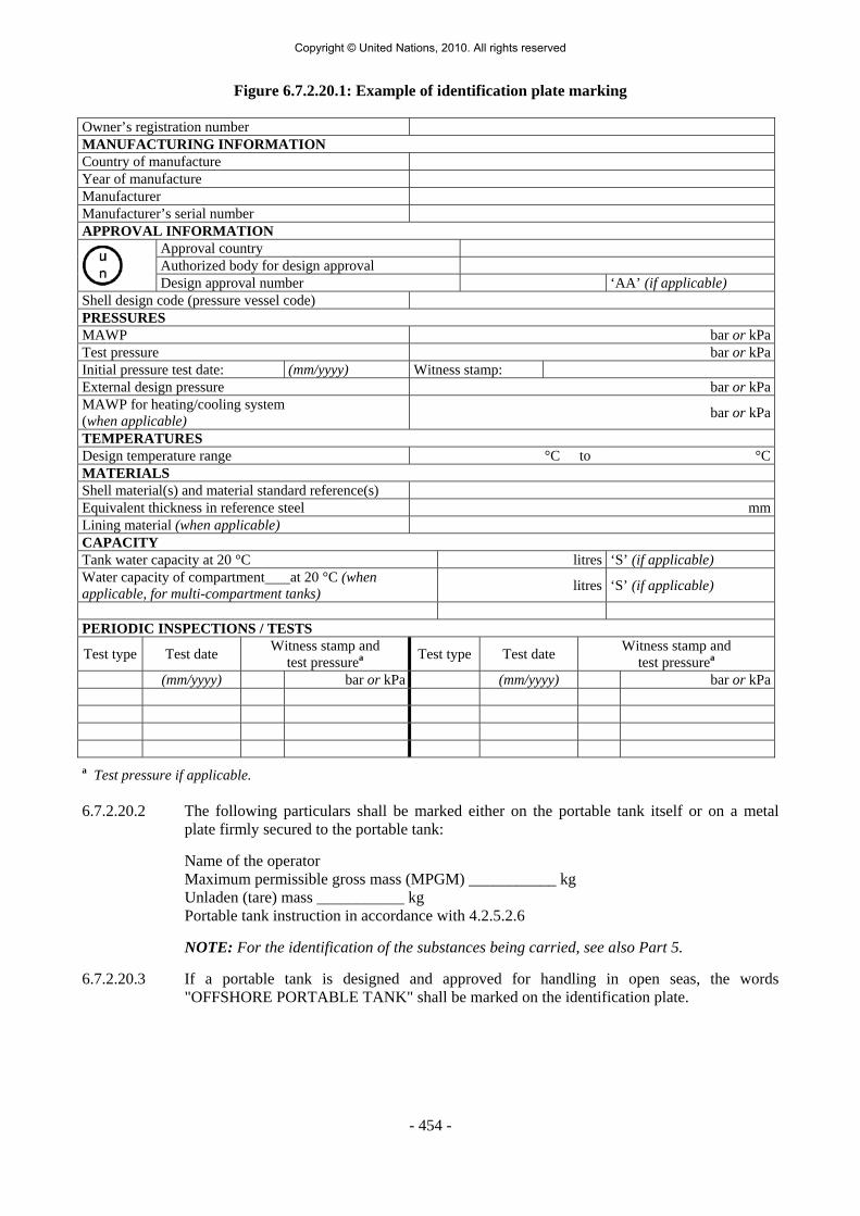
- 454 -
Figure 6.7.2.20.1: Example of identification plate marking
Owner’s registration number MANUFACTURING INFORMATION Country of manufacture Year of manufacture Manufacturer Manufacturer’s serial number APPROVAL INFORMATION
Approval country Authorized body for design approval
Design approval number ‘AA’ (if applicable) Shell design code (pressure vessel code) PRESSURES MAWP bar or kPaTest pressure bar or kPaInitial pressure test date: (mm/yyyy) Witness stamp: External design pressure bar or kPaMAWP for heating/cooling system (when applicable) bar or kPa
TEMPERATURES Design temperature range °C to °CMATERIALS Shell material(s) and material standard reference(s) Equivalent thickness in reference steel mmLining material (when applicable) CAPACITY Tank water capacity at 20 °C litres ‘S’ (if applicable) Water capacity of compartment at 20 °C (when applicable, for multi-compartment tanks) litres ‘S’ (if applicable)
PERIODIC INSPECTIONS / TESTS
Test type Test date Witness stamp and test pressurea Test type Test date Witness stamp and
test pressurea
(mm/yyyy) bar or kPa (mm/yyyy) bar or kPa a Test pressure if applicable. 6.7.2.20.2 The following particulars shall be marked either on the portable tank itself or on a metal
plate firmly secured to the portable tank:
Name of the operator Maximum permissible gross mass (MPGM) ___________ kg Unladen (tare) mass ___________ kg Portable tank instruction in accordance with 4.2.5.2.6 NOTE: For the identification of the substances being carried, see also Part 5.
6.7.2.20.3 If a portable tank is designed and approved for handling in open seas, the words "OFFSHORE PORTABLE TANK" shall be marked on the identification plate.
Copyright © United Nations, 2010. All rights reserved

- 455 -
6.7.3 Requirements for the design, construction, inspection and testing of portable tanks intended for the carriage of non-refrigerated liquefied gases
6.7.3.1 Definitions For the purposes of this section: Alternative arrangement means an approval granted by the competent authority for a
portable tank or MEGC that has been designed, constructed or tested to technical requirements or testing methods other than those specified in this Chapter;
Portable tank means a multimodal tank having a capacity of more than 450 litres used for
the carriage of non-refrigerated liquefied gases of Class 2. The portable tank includes a shell fitted with service equipment and structural equipment necessary for the carriage of gases. The portable tank shall be capable of being filled and discharged without the removal of its structural equipment. It shall possess stabilizing members external to the shell, and shall be capable of being lifted when full. It shall be designed primarily to be loaded onto a vehicle, wagon or sea-going or inland navigation vessel and shall be equipped with skids, mountings or accessories to facilitate mechanical handling. Tank-vehicles, tank-wagons, non-metallic tanks, intermediate bulk containers (IBCs), gas cylinders and large receptacles are not considered to fall within the definition for portable tanks;
Shell means the part of the portable tank which retains the non-refrigerated liquefied gas
intended for carriage (tank proper), including openings and their closures, but does not include service equipment or external structural equipment;
Service equipment means measuring instruments and filling, discharge, venting, safety and
insulating devices;
Structural equipment means the reinforcing, fastening, protective and stabilizing members external to the shell;
Maximum allowable working pressure (MAWP) means a pressure that shall be not less than
the highest of the following pressures measured at the top of the shell while in operating position, but in no case less than 7 bar:
(a) The maximum effective gauge pressure allowed in the shell during filling or
discharge; or (b) The maximum effective gauge pressure to which the shell is designed, which shall be:
(i) for a non-refrigerated liquefied gas listed in the portable tank instruction T50 in 4.2.5.2.6, the MAWP (in bar) given in T50 portable tank instruction for that gas;
(ii) for other non-refrigerated liquefied gases, not less than the sum of:
- the absolute vapour pressure (in bar) of the non-refrigerated liquefied gas
at the design reference temperature minus 1 bar; and - the partial pressure (in bar) of air or other gases in the ullage space
being determined by the design reference temperature and the liquid phase expansion due to an increase of the mean bulk temperature of tr -tf (tf = filling temperature, usually 15 °C, tr = maximum mean bulk temperature, 50 °C);
Copyright © United Nations, 2010. All rights reserved

- 456 -
Design pressure means the pressure to be used in calculations required by a recognized pressure vessel code. The design pressure shall be not less than the highest of the following pressures:
(a) The maximum effective gauge pressure allowed in the shell during filling or
discharge; or (b) The sum of:
(i) the maximum effective gauge pressure to which the shell is designed as defined
in (b) of the MAWP definition (see above); and (ii) a head pressure determined on the basis of the static forces specified
in 6.7.3.2.9, but not less than 0.35 bar; Test pressure means the maximum gauge pressure at the top of the shell during the pressure
test; Leakproofness test means a test using gas subjecting the shell and its service equipment to an
effective internal pressure of not less than 25% of the MAWP; Maximum permissible gross mass (MPGM) means the sum of the tare mass of the portable
tank and the heaviest load authorized for carriage; Reference steel means a steel with a tensile strength of 370 N/mm2 and an elongation at
fracture of 27%; Mild steel means a steel with a guaranteed minimum tensile strength of 360 N/mm2
to 440 N/mm2 and a guaranteed minimum elongation at fracture conforming to 6.7.3.3.3.3;
Design temperature range for the shell shall be -40 °C to 50 °C for non-refrigerated liquefied gases carried under ambient conditions. More severe design temperatures shall be considered for portable tanks subjected to severe climatic conditions;
Design reference temperature means the temperature at which the vapour pressure of the
contents is determined for the purpose of calculating the MAWP. The design reference temperature shall be less than the critical temperature of the non-refrigerated liquefied gas intended to be carried to ensure that the gas at all times is liquefied. This value for each portable tank type is as follows:
(a) Shell with a diameter of 1.5 metres or less: 65 °C; (b) Shell with a diameter of more than 1.5 metres:
(i) without insulation or sun shield: 60 °C; (ii) with sun shield (see 6.7.3.2.12): 55 °C; and (iii) with insulation (see 6.7.3.2.12) : 50 °C;
Filling density means the average mass of non-refrigerated liquefied gas per litre of shell capacity (kg/l). The filling density is given in portable tank instruction T50 in 4.2.5.2.6.
6.7.3.2 General design and construction requirements 6.7.3.2.1 Shells shall be designed and constructed in accordance with the requirements of a pressure
vessel code recognized by the competent authority. Shells shall be made of steel suitable for forming. The materials shall in principle conform to national or international material standards. For welded shells, only a material whose weldability has been fully demonstrated
Copyright © United Nations, 2010. All rights reserved

- 457 -
shall be used. Welds shall be skilfully made and afford complete safety. When the manufacturing process or the materials make it necessary, the shells shall be suitability heat-treated to guarantee adequate toughness in the weld and in the heat affected zones. In choosing the material the design temperature range shall be taken into account with respect to risk of brittle fracture, to stress corrosion cracking and to resistance to impact. When fine grain steel is used, the guaranteed value of the yield strength shall be not more than 460 N/mm2 and the guaranteed value of the upper limit of the tensile strength shall be not more than 725 N/mm2 according to the material specification. Portable tank materials shall be suitable for the external environment in which they may be carried.
6.7.3.2.2 Portable tank shells, fittings and pipework shall be constructed of materials which are:
(a) Substantially immune to attack by the non-refrigerated liquefied gas(es) intended to be carried; or
(b) Properly passivated or neutralized by chemical reaction.
6.7.3.2.3 Gaskets shall be made of materials compatible with the non-refrigerated liquefied gas(es) intended to be carried.
6.7.3.2.4 Contact between dissimilar metals which could result in damage by galvanic action shall be
avoided. 6.7.3.2.5 The materials of the portable tank, including any devices, gaskets, and accessories, shall not
adversely affect the non-refrigerated liquefied gas(es) intended for carriage in the portable tank.
6.7.3.2.6 Portable tanks shall be designed and constructed with supports to provide a secure base
during carriage and with suitable lifting and tie-down attachments.
6.7.3.2.7 Portable tanks shall be designed to withstand, without loss of contents, at least the internal pressure due to the contents, and the static, dynamic and thermal loads during normal conditions of handling and carriage. The design shall demonstrate that the effects of fatigue, caused by repeated application of these loads through the expected life of the portable tank, have been taken into account.
6.7.3.2.8 Shells shall be designed to withstand an external pressure of at least 0.4 bar (gauge pressure)
above the internal pressure without permanent deformation. When the shell is to be subjected to a significant vacuum before filling or during discharge it shall be designed to withstand an external pressure of at least 0.9 bar (gauge pressure) above the internal pressure and shall be proven at that pressure.
6.7.3.2.9 Portable tanks and their fastenings shall, under the maximum permissible load, be capable of
absorbing the following separately applied static forces:
(a) In the direction of travel: twice the MPGM multiplied by the acceleration due to gravity (g) 1;
(b) Horizontally at right angles to the direction of travel: the MPGM (when the direction
of travel is not clearly determined, the forces shall be equal to twice the MPGM) multiplied by the acceleration due to gravity (g) 1;
(c) Vertically upwards: the MPGM multiplied by the acceleration due to gravity (g) 1; and (d) Vertically downwards: twice the MPGM (total loading including the effect of gravity)
multiplied by the acceleration due to gravity (g) 1.
1 For calculation purposes g = 9.81 m/s2.
Copyright © United Nations, 2010. All rights reserved

- 458 -
6.7.3.2.10 Under each of the forces in 6.7.3.2.9, the safety factor to be observed shall be as follows:
(a) For steels having a clearly defined yield point, a safety factor of 1.5 in relation to the guaranteed yield strength; or
(b) For steels with no clearly defined yield point, a safety factor of 1.5 in relation to the
guaranteed 0.2% proof strength and, for austenitic steels, the 1% proof strength.
6.7.3.2.11 The values of yield strength or proof strength shall be the values according to national or international material standards. When austenitic steels are used, the specified minimum values of yield strength and proof strength according to the material standards may be increased by up to 15% when these greater values are attested in the material inspection certificate. When no material standard exists for the steel in question, the value of yield strength or proof strength used shall be approved by the competent authority.
6.7.3.2.12 When the shells intended for the carriage of non-refrigerated liquefied gases are equipped
with thermal insulation, the thermal insulation systems shall satisfy the following requirements:
(a) It shall consist of a shield covering not less than the upper third but not more than the
upper half of the surface of the shell and separated from the shell by an air space about 40 mm across;
(b) It shall consist of a complete cladding of adequate thickness of insulating materials
protected so as to prevent the ingress of moisture and damage under normal conditions of carriage and so as to provide a thermal conductance of not more than 0.67 (W.m-2.K-1);
(c) When the protective covering is so closed as to be gas-tight, a device shall be provided to prevent any dangerous pressure from developing in the insulating layer in the event of inadequate gas tightness of the shell or of its items of equipment; and
(d) The thermal insulation shall not inhibit access to the fittings and discharge devices.
6.7.3.2.13 Portable tanks intended for the carriage of flammable non-refrigerated liquefied gases shall be capable of being electrically earthed.
6.7.3.3 Design criteria
6.7.3.3.1 Shells shall be of a circular cross-section.
6.7.3.3.2 Shells shall be designed and constructed to withstand a test pressure not less than 1.3 times the design pressure. The shell design shall take into account the minimum MAWP values provided in portable tank instruction T50 in 4.2.5.2.6 for each non-refrigerated liquefied gas intended for carriage. Attention is drawn to the minimum shell thickness requirements for these shells specified in 6.7.3.4.
6.7.3.3.3 For steels exhibiting a clearly defined yield point or characterized by a guaranteed proof strength (0.2% proof strength, generally, or 1% proof strength for austenitic steels) the primary membrane stress σ (sigma) in the shell shall not exceed 0.75 Re or 0.50 Rm, whichever is lower, at the test pressure, where:
Re = yield strength in N/mm2, or 0.2% proof strength or, for austenitic steels, 1% proof stress;
Rm = minimum tensile strength in N/mm2.
Copyright © United Nations, 2010. All rights reserved

- 459 -
6.7.3.3.3.1 The values of Re and Rm to be used shall be the specified minimum values according to national or international material standards. When austenitic steels are used, the specified minimum values for Re and Rm according to the material standards may be increased by up to 15% when these greater values are attested in the material inspection certificate. When no material standard exists for the steel in question, the values of Re and Rm used shall be approved by the competent authority or its authorized body.
6.7.3.3.3.2 Steels which have a Re/Rm ratio of more than 0.85 are not allowed for the construction of welded shells. The values of Re and Rm to be used in determining this ratio shall be the values specified in the material inspection certificate.
6.7.3.3.3.3 Steels used in the construction of shells shall have an elongation at fracture, in %, of not less than 10 000/Rm with an absolute minimum of 16% for fine grain steels and 20% for other steels.
6.7.3.3.3.4 For the purpose of determining actual values for materials, it shall be noted that for sheet metal, the axis of the tensile test specimen shall be at right angles (transversely) to the direction of rolling. The permanent elongation at fracture shall be measured on test specimens of rectangular cross sections in accordance with ISO 6892:1998 using a 50 mm gauge length.
6.7.3.4 Minimum shell thickness 6.7.3.4.1 The minimum shell thickness shall be the greater thickness based on:
(a) The minimum thickness determined in accordance with the requirements in 6.7.3.4; and
(b) The minimum thickness determined in accordance with the recognized pressure vessel
code including the requirements in 6.7.3.3.
6.7.3.4.2 The cylindrical portions, ends (heads) and manhole covers of shells of not more than 1.80 m in diameter shall be not less than 5 mm thick in the reference steel or of equivalent thickness in the steel to be used. Shells of more than 1.80 m in diameter shall be not less than 6 mm thick in the reference steel or of equivalent thickness in the steel to be used.
6.7.3.4.3 The cylindrical portions, ends (heads) and manhole covers of all shells shall be not less
than 4 mm thick regardless of the material of construction. 6.7.3.4.4 The equivalent thickness of a steel other than the thickness prescribed for the reference steel
in 6.7.3.4.2 shall be determined using the following formula:
13
1
o1
A Rme4,21
e×
=
where:
e1 = required equivalent thickness (in mm) of the steel to be used;
e0 = minimum thickness (in mm) for the reference steel specified in 6.7.3.4.2;
Rm1 = guaranteed minimum tensile strength (in N/mm2) of the steel to be used (see 6.7.3.3.3);
A1 = guaranteed minimum elongation at fracture (in %) of the steel to be used according to national or international standards.
Copyright © United Nations, 2010. All rights reserved

- 460 -
6.7.3.4.5 In no case shall the wall thickness be less than that prescribed in 6.7.3.4.1 to 6.7.3.4.3. All parts of the shell shall have a minimum thickness as determined by 6.7.3.4.1 to 6.7.3.4.3. This thickness shall be exclusive of any corrosion allowance.
6.7.3.4.6 When mild steel is used (see 6.7.3.1), calculation using the formula in 6.7.3.4.4 is not
required. 6.7.3.4.7 There shall be no sudden change of plate thickness at the attachment of the ends (heads) to
the cylindrical portion of the shell. 6.7.3.5 Service equipment 6.7.3.5.1 Service equipment shall be so arranged as to be protected against the risk of being wrenched
off or damaged during handling and carriage. When the connection between the frame and the shell allows relative movement between the sub-assemblies, the equipment shall be so fastened as to permit such movement without risk of damage to working parts. The external discharge fittings (pipe sockets, shut-off devices), the internal stop-valve and its seating shall be protected against the danger of being wrenched off by external forces (for example using shear sections). The filling and discharge devices (including flanges or threaded plugs) and any protective caps shall be capable of being secured against unintended opening.
6.7.3.5.2 All openings with a diameter of more than 1.5 mm in shells of portable tanks, except
openings for pressure-relief devices, inspection openings and closed bleed holes, shall be fitted with at least three mutually independent shut-off devices in series, the first being an internal stop-valve, excess flow valve or equivalent device, the second being an external stop-valve and the third being a blank flange or equivalent device.
6.7.3.5.2.1 When a portable tank is fitted with an excess flow valve, the excess flow valve shall be so
fitted that its seating is inside the shell or inside a welded flange or, when fitted externally, its mountings shall be designed so that in the event of impact its effectiveness shall be maintained. The excess flow valves shall be selected and fitted so as to close automatically when the rated flow specified by the manufacturer is reached. Connections and accessories leading to or from such a valve shall have a capacity for a flow more than the rated flow of the excess flow valve.
6.7.3.5.3 For filling and discharge openings, the first shut-off device shall be an internal stop-valve
and the second shall be a stop-valve placed in an accessible position on each discharge and filling pipe.
6.7.3.5.4 For filling and discharge bottom openings of portable tanks intended for the carriage of
flammable and/or toxic non-refrigerated liquefied gases the internal stop-valve shall be a quick closing safety device which closes automatically in the event of unintended movement of the portable tank during filling or discharge or fire engulfment. Except for portable tanks having a capacity of not more than 1 000 litres, it shall be possible to operate this device by remote control.
6.7.3.5.5 In addition to filling, discharge and gas pressure equalizing orifices, shells may have
openings in which gauges, thermometers and manometers can be fitted. Connections for such instruments shall be made by suitable welded nozzles or pockets and not be screwed connections through the shell.
6.7.3.5.6 All portable tanks shall be fitted with manholes or other inspection openings of suitable size
to allow for internal inspection and adequate access for maintenance and repair of the interior.
Copyright © United Nations, 2010. All rights reserved

- 461 -
6.7.3.5.7 External fittings shall be grouped together so far as reasonably practicable. 6.7.3.5.8 Each connection on a portable tank shall be clearly marked to indicate its function. 6.7.3.5.9 Each stop-valve or other means of closure shall be designed and constructed to a rated
pressure not less than the MAWP of the shell taking into account the temperatures expected during carriage. All stop-valves with a screwed spindle shall close by a clockwise motion of the handwheel. For other stop-valves the position (open and closed) and direction of closure shall be clearly indicated. All stop-valves shall be designed to prevent unintentional opening.
6.7.3.5.10 Piping shall be designed, constructed and installed so as to avoid the risk of damage due to
thermal expansion and contraction, mechanical shock and vibration. All piping shall be of suitable metallic material. Welded pipe joints shall be used wherever possible.
6.7.3.5.11 Joints in copper tubing shall be brazed or have an equally strong metal union. The melting
point of brazing materials shall be no lower than 525 °C. The joints shall not decrease the strength of tubing as may happen when cutting threads.
6.7.3.5.12 The burst pressure of all piping and pipe fittings shall be not less than the highest of four
times the MAWP of the shell or four times the pressure to which it may be subjected in service by the action of a pump or other device (except pressure-relief devices).
6.7.3.5.13 Ductile metals shall be used in the construction of valves and accessories. 6.7.3.6 Bottom openings 6.7.3.6.1 Certain non-refrigerated liquefied gases shall not be carried in portable tanks with bottom
openings when portable tank instruction T50 in 4.2.5.2.6 indicates that bottom openings are not allowed. There shall be no openings below the liquid level of the shell when it is filled to its maximum permissible filling limit.
6.7.3.7 Pressure-relief devices 6.7.3.7.1 Portable tanks shall be provided with one or more spring-loaded pressure-relief devices. The
pressure-relief devices shall open automatically at a pressure not less than the MAWP and be fully open at a pressure equal to 110% of the MAWP. These devices shall, after discharge, close at a pressure not lower than 10% below the pressure at which discharge starts and shall remain closed at all lower pressures. The pressure-relief devices shall be of a type that will resist dynamic forces including liquid surge. Frangible discs not in series with a spring-loaded pressure-relief device are not permitted.
6.7.3.7.2 Pressure-relief devices shall be designed to prevent the entry of foreign matter, the leakage
of gas and the development of any dangerous excess pressure. 6.7.3.7.3 Portable tanks intended for the carriage of certain non-refrigerated liquefied gases identified
in portable tank instruction T50 in 4.2.5.2.6 shall have a pressure-relief device approved by the competent authority. Unless a portable tank in dedicated service is fitted with an approved relief device constructed of materials compatible with the load, such device shall comprise a frangible disc preceding a spring-loaded device. The space between the frangible disc and the device shall be provided with a pressure gauge or a suitable tell-tale indicator. This arrangement permits the detection of disc rupture, pinholing or leakage which could cause a malfunction of the pressure-relief device. The frangible discs shall rupture at a nominal pressure 10% above the start-to-discharge pressure of the relief device.
Copyright © United Nations, 2010. All rights reserved

- 462 -
6.7.3.7.4 In the case of multi-purpose portable tanks, the pressure-relief devices shall open at a pressure indicated in 6.7.3.7.1 for the gas having the highest maximum allowable pressure of the gases allowed to be carried in the portable tank.
6.7.3.8 Capacity of relief devices 6.7.3.8.1 The combined delivery capacity of the relief devices shall be sufficient that, in the event of
total fire engulfment, the pressure (including accumulation) inside the shell does not exceed 120% of the MAWP. Spring-loaded relief devices shall be used to achieve the full relief capacity prescribed. In the case of multi-purpose tanks, the combined delivery capacity of the pressure-relief devices shall be taken for the gas which requires the highest delivery capacity of the gases allowed to be carried in portable tanks.
6.7.3.8.1.1 To determine the total required capacity of the relief devices, which shall be regarded as
being the sum of the individual capacities of the several devices, the following formulae 4 shall be used:
MZT
LCFA 12.4 Q
0.82
=
where:
Q = minimum required rate of discharge in cubic metres of air per second (m3/s) at standard conditions: 1 bar and 0 °C (273 K);
F = is a coefficient with the following value:
for uninsulated shells: F = 1;
for insulated shells: F = U(649-t)/13.6 but in no case is less than 0.25
where: U = thermal conductance of the insulation, in Kw.m-2.K-1, at 38 °C; t = actual temperature of the non-refrigerated liquefied gas during
filling (°C); when this temperature is unknown, let t=15 °C;
The value of F given above for insulated shells may be taken provided that the insulation is in accordance with 6.7.3.8.1.2; where: A = total external surface area of shell in square metres; Z = the gas compressibility factor in the accumulating condition (when
this factor is unknown, let Z =1.0); T = absolute temperature in Kelvin (°C + 273) above the pressure relief
devices in the accumulating condition;
4 This formula applies only to non-refrigerated liquefied gases which have critical temperatures well above the temperature at the accumulating condition. For gases which have critical temperatures near or below the temperature at the accumulating condition, the calculation of the pressure-relief device delivery capacity shall consider further thermodynamic properties of the gas (see for example CGA S-1.2-2003 "Pressure Relief Device Standards - Part 2 - Cargo and Portable Tanks for Compressed Gases").
Copyright © United Nations, 2010. All rights reserved

- 463 -
L = the latent heat of vaporization of the liquid, in kJ/kg, in the accumulating condition;
M = molecular mass of the discharged gas; C = a constant which is derived from one of the following formulae as
a function of the ratio k of specific heats
v
p
cc
k =
where
cp is the specific heat at constant pressure; and cv is the specific heat at constant volume.
when k>1:
1k1k
1 k2k C
−+
⎟⎠⎞
⎜⎝⎛
+=
when k = 1 or k is unknown:
607.0e
1C ==
where e is the mathematical constant 2.7183
C may also be taken from the following table:
k C k C k C
1.00 0.607 1.26 0.660 1.52 0.704 1.02 0.611 1.28 0.664 1.54 0.707 1.04 0.615 1.30 0.667 1.56 0.710 1.06 0.620 1.32 0.671 1.58 0.713 1.08 0.624 1.34 0.674 1.60 0.716 1.10 0.628 1.36 0.678 1.62 0.719 1.12 0.633 1.38 0.681 1.64 0.722 1.14 0.637 1.40 0.685 1.66 0.725 1.16 0.641 1.42 0.688 1.68 0.728 1.18 0.645 1.44 0.691 1.70 0.731 1.20 0.649 1.46 0.695 2.00 0.770 1.22 0.652 1.48 0.698 2.20 0.793 1.24 0.656 1.50 0.701
6.7.3.8.1.2 Insulation systems, used for the purpose of reducing the venting capacity, shall be approved
by the competent authority or its authorized body. In all cases, insulation systems approved for this purpose shall:
(a) Remain effective at all temperatures up to 649 °C; and (b) Be jacketed with a material having a melting point of 700 °C or greater.
Copyright © United Nations, 2010. All rights reserved

- 464 -
6.7.3.9 Marking of pressure-relief devices 6.7.3.9.1 Every pressure-relief device shall be plainly and permanently marked with the following
particulars:
(a) The pressure (in bar or kPa) at which it is set to discharge; (b) The allowable tolerance at the discharge pressure for spring-loaded devices; (c) The reference temperature corresponding to the rated pressure for frangible discs; and (d) The rated flow capacity of the device in standard cubic metres of air per second (m3/s).
When practicable, the following information shall also be shown: (e) The manufacturer's name and relevant catalogue number of the device.
6.7.3.9.2 The rated flow capacity marked on the pressure-relief devices shall be determined according
to ISO 4126-1:1991.
6.7.3.10 Connections to pressure-relief devices 6.7.3.10.1 Connections to pressure-relief devices shall be of sufficient size to enable the required
discharge to pass unrestricted to the safety device. No stop-valve shall be installed between the shell and the pressure-relief devices except when duplicate devices are provided for maintenance or other reasons and the stop-valves serving the devices actually in use are locked open or the stop-valves are interlocked so that at least one of the duplicate devices is always operable and capable of meeting the requirements of 6.7.3.8. There shall be no obstruction in an opening leading to a vent or pressure-relief device which might restrict or cut-off the flow from the shell to that device. Vents from the pressure-relief devices, when used, shall deliver the relieved vapour or liquid to the atmosphere in conditions of minimum back-pressure on the relieving device.
6.7.3.11 Siting of pressure-relief devices 6.7.3.11.1 Each pressure-relief device inlet shall be situated on top of the shell in a position as near the
longitudinal and transverse centre of the shell as reasonably practicable. All pressure relief device inlets shall under maximum filling conditions be situated in the vapour space of the shell and the devices shall be so arranged as to ensure that the escaping vapour is discharged unrestrictedly. For flammable non-refrigerated liquefied gases, the escaping vapour shall be directed away from the shell in such a manner that it cannot impinge upon the shell. Protective devices which deflect the flow of vapour are permissible provided the required relief-device capacity is not reduced.
6.7.3.11.2 Arrangements shall be made to prevent access to the pressure-relief devices by unauthorized
persons and to protect the devices from damage caused by the portable tank overturning. 6.7.3.12 Gauging devices 6.7.3.12.1 Unless a portable tank is intended to be filled by weight it shall be equipped with one or
more gauging devices. Glass level-gauges and gauges made of other fragile material, which are in direct communication with the contents of the shell shall not be used.
Copyright © United Nations, 2010. All rights reserved

- 465 -
6.7.3.13 Portable tank supports, frameworks, lifting and tie-down attachments 6.7.3.13.1 Portable tanks shall be designed and constructed with a support structure to provide a secure
base during carriage. The forces specified in 6.7.3.2.9 and the safety factor specified in 6.7.3.2.10 shall be considered in this aspect of the design. Skids, frameworks, cradles or other similar structures are acceptable.
6.7.3.13.2 The combined stresses caused by portable tank mountings (e.g. cradles, frameworks, etc.)
and portable tank lifting and tie-down attachments shall not cause excessive stress in any portion of the shell. Permanent lifting and tie-down attachments shall be fitted to all portable tanks. Preferably they shall be fitted to the portable tank supports but may be secured to reinforcing plates located on the shell at the points of support.
6.7.3.13.3 In the design of supports and frameworks the effects of environmental corrosion shall be
taken into account. 6.7.3.13.4 Forklift pockets shall be capable of being closed off. The means of closing forklift pockets
shall be a permanent part of the framework or permanently attached to the framework. Single compartment portable tanks with a length less than 3.65 m need not have closed off forklift pockets provided that:
(a) The shell and all the fittings are well protected from being hit by the forklift blades;
and
(b) The distance between the centres of the forklift pockets is at least half of the maximum length of the portable tank.
6.7.3.13.5 When portable tanks are not protected during carriage, according to 4.2.2.3, the shells and
service equipment shall be protected against damage to the shell and service equipment resulting from lateral or longitudinal impact or overturning. External fittings shall be protected so as to preclude the release of the shell contents upon impact or overturning of the portable tank on its fittings. Examples of protection include:
(a) Protection against lateral impact which may consist of longitudinal bars protecting the
shell on both sides at the level of the median line; (b) Protection of the portable tank against overturning which may consist of
reinforcement rings or bars fixed across the frame; (c) Protection against rear impact which may consist of a bumper or frame; (d) Protection of the shell against damage from impact or overturning by use of an
ISO frame in accordance with ISO 1496-3:1995. 6.7.3.14 Design approval 6.7.3.14.1 The competent authority or its authorized body shall issue a design approval certificate for
any new design of a portable tank. This certificate shall attest that a portable tank has been surveyed by that authority, is suitable for its intended purpose and meets the requirements of this Chapter and where appropriate the provisions for gases provided in portable tank instruction T50 in 4.2.5.2.6. When a series of portable tanks are manufactured without change in the design, the certificate shall be valid for the entire series. The certificate shall refer to the prototype test report, the gases allowed to be carried, the materials of construction of the shell and an approval number. The approval number shall consist of the distinguishing sign or mark of the State in whose territory the approval was granted, i.e. the distinguishing sign for use in international traffic, as prescribed by the Convention on Road Traffic, Vienna 1968, and a registration number. Any alternative arrangements according
Copyright © United Nations, 2010. All rights reserved
- 466 -
to 6.7.1.2 shall be indicated on the certificate. A design approval may serve for the approval of smaller portable tanks made of materials of the same kind and thickness, by the same fabrication techniques and with identical supports, equivalent closures and other appurtenances.
6.7.3.14.2 The prototype test report for the design approval shall include at least the following:
(a) The results of the applicable framework test specified in ISO 1496-3:1995; (b) The results of the initial inspection and test in 6.7.3.15.3; and (c) The results of the impact test in 6.7.3.15.1, when applicable.
6.7.3.15 Inspection and testing 6.7.3.15.1 Portable tanks meeting the definition of container in the International Convention for Safe
Containers (CSC), 1972, as amended, shall not be used unless they are successfully qualified by subjecting a representative prototype of each design to the Dynamic, Longitudinal Impact Test prescribed in the Manual of Tests and Criteria, Part IV, Section 41.
6.7.3.15.2 The shell and items of equipment of each portable tank shall be inspected and tested before
being put into service for the first time (initial inspection and test) and thereafter at not more than five-year intervals (5 year periodic inspection and test) with an intermediate periodic inspection and test (2.5 year periodic inspection and test) midway between the 5 year periodic inspections and tests. The 2.5 year inspection and test may be performed within 3 months of the specified date. An exceptional inspection and test shall be performed regardless of the last periodic inspection and test when necessary according to 6.7.3.15.7.
6.7.3.15.3 The initial inspection and test of a portable tank shall include a check of the design
characteristics, an internal and external examination of the portable tank and its fittings with due regard to the non-refrigerated liquefied gases to be carried, and a pressure test referring to the test pressures according to 6.7.3.3.2. The pressure test may be performed as a hydraulic test or by using another liquid or gas with the agreement of the competent authority or its authorized body. Before the portable tank is placed into service, a leakproofness test and a test of the satisfactory operation of all service equipment shall also be performed. When the shell and its fittings have been pressure-tested separately, they shall be subjected together after assembly to a leakproofness test. All welds subject to full stress level in the shell shall be inspected during the initial test by radiographic, ultrasonic, or another suitable non-destructive test method. This does not apply to the jacket.
6.7.3.15.4 The 5 year periodic inspection and test shall include an internal and external examination
and, as a general rule, a hydraulic pressure test. Sheathing, thermal insulation and the like shall be removed only to the extent required for reliable appraisal of the condition of the portable tank. When the shell and equipment have been pressure-tested separately, they shall be subjected together after assembly to a leakproofness test.
6.7.3.15.5 The intermediate 2.5 year periodic inspection and test shall at least include an internal and
external examination of the portable tank and its fittings with due regard to the non-refrigerated liquefied gases intended to be carried, a leakproofness test and a check of the satisfactory operation of all service equipment. Sheathing thermal insulation and the like shall be removed only to the extent required for reliable appraisal of the condition of the portable tank. For portable tanks intended for the carriage of a single non-refrigerated liquefied gas, the 2.5 year internal examination may be waived or substituted by other test methods or inspection procedures specified by the competent authority or its authorized body.
Copyright © United Nations, 2010. All rights reserved

- 467 -
6.7.3.15.6 A portable tank may not be filled and offered for carriage after the date of expiry of the last 5 year or 2.5 year periodic inspection and test as required by 6.7.3.15.2. However a portable tank filled prior to the date of expiry of the last periodic inspection and test may be carried for a period not to exceed three months beyond the date of expiry of the last periodic test or inspection. In addition, a portable tank may be carried after the date of expiry of the last periodic test and inspection:
(a) After emptying but before cleaning, for purposes of performing the next required test
or inspection prior to refilling; and (b) Unless otherwise approved by the competent authority, for a period not to exceed
six months beyond the date of expiry of the last periodic test or inspection, in order to allow the return of dangerous goods for proper disposal or recycling. Reference to this exemption shall be mentioned in the transport document.
6.7.3.15.7 The exceptional inspection and test is necessary when the portable tank shows evidence of
damaged or corroded areas, or leakage, or other conditions that indicate a deficiency that could affect the integrity of the portable tank. The extent of the exceptional inspection and test shall depend on the amount of damage or deterioration of the portable tank. It shall include at least the 2.5 year inspection and test according to 6.7.3.15.5.
6.7.3.15.8 The internal and external examinations shall ensure that:
(a) The shell is inspected for pitting, corrosion, or abrasions, dents, distortions, defects in welds or any other conditions, including leakage, that might render the portable tank unsafe for carriage;
(b) The piping, valves, and gaskets are inspected for corroded areas, defects, or any other
conditions, including leakage, that might render the portable tank unsafe for filling, discharge or carriage;
(c) Devices for tightening manhole covers are operative and there is no leakage at
manhole covers or gaskets; (d) Missing or loose bolts or nuts on any flanged connection or blank flange are replaced
or tightened; (e) All emergency devices and valves are free from corrosion, distortion and any damage
or defect that could prevent their normal operation. Remote closure devices and self-closing stop-valves shall be operated to demonstrate proper operation;
(f) Required markings on the portable tank are legible and in accordance with the
applicable requirements; and (g) The framework, the supports and the arrangements for lifting the portable tank are in
satisfactory condition. 6.7.3.15.9 The inspections and tests in 6.7.3.15.1, 6.7.3.15.3, 6.7.3.15.4, 6.7.3.15.5 and 6.7.3.15.7 shall
be performed or witnessed by an expert approved by the competent authority or its authorized body. When the pressure test is a part of the inspection and test, the test pressure shall be the one indicated on the data plate of the portable tank. While under pressure, the portable tank shall be inspected for any leaks in the shell, piping or equipment.
Copyright © United Nations, 2010. All rights reserved

- 468 -
6.7.3.15.10 In all cases when cutting, burning or welding operations on the shell have been effected, that work shall be to the approval of the competent authority or its authorized body taking into account the pressure vessel code used for the construction of the shell. A pressure test to the original test pressure shall be performed after the work is completed.
6.7.3.15.11 When evidence of any unsafe condition is discovered, the portable tank shall not be returned
to service until it has been corrected and the pressure test is repeated and passed. 6.7.3.16 Marking 6.7.3.16.1 Every portable tank shall be fitted with a corrosion resistant metal plate permanently
attached to the portable tank in a conspicuous place readily accessible for inspection. When for reasons of portable tank arrangements the plate cannot be permanently attached to the shell, the shell shall be marked with at least the information required by the pressure vessel code. As a minimum, at least the following information shall be marked on the plate by stamping or by any other similar method: (a) Owner information
(i) Owner’s registration number;
(b) Manufacturing information
(i) Country of manufacture;
(ii) Year of manufacture;
(iii) Manufacturer’s name or mark;
(iv) Manufacturer’s serial number;
(c) Approval information
(i) The United Nations packaging symbol
;
This symbol shall not be used for any purpose other than certifying that a
packaging, a portable tank or a MEGC complies with the relevant requirements in Chapter 6.1, 6.2, 6.3, 6.5, 6.6 or 6.7;
(ii) Approval country;
(iii) Authorized body for the design approval;
(iv) Design approval number;
(v) Letters ‘AA’, if the design was approved under alternative arrangements (see 6.7.1.2);
(vi) Pressure vessel code to which the shell is designed;
(d) Pressures
(i) MAWP (in bar gauge or kPa gauge)2;
(ii) Test pressure (in bar gauge or kPa gauge)2;
(iii) Initial pressure test date (month and year);
(iv) Identification mark of the initial pressure test witness;
(v) External design pressure5 (in bar gauge or kPa gauge)2;
2 The unit used shall be indicated. 5 See 6.7.3.2.8.
Copyright © United Nations, 2010. All rights reserved
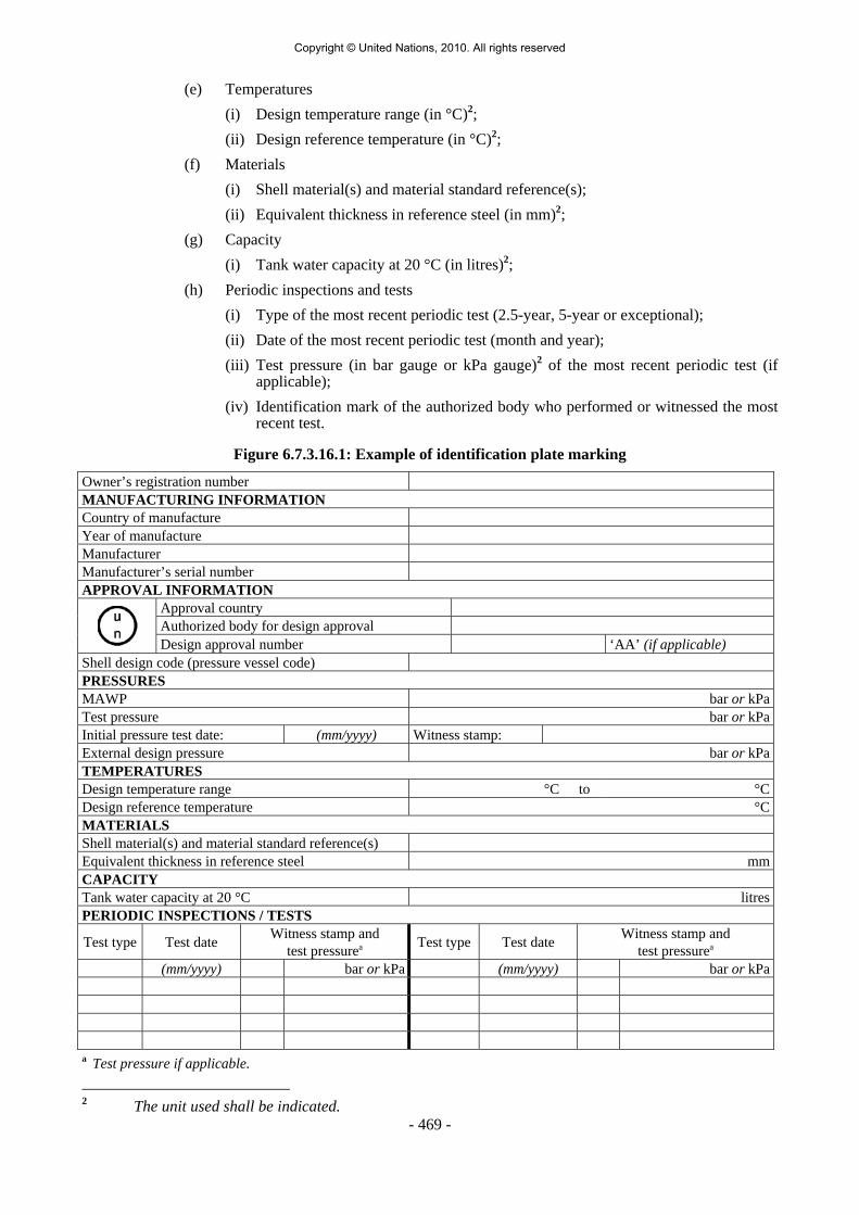
- 469 -
(e) Temperatures (i) Design temperature range (in °C)2; (ii) Design reference temperature (in °C)2; (f) Materials (i) Shell material(s) and material standard reference(s); (ii) Equivalent thickness in reference steel (in mm)2; (g) Capacity (i) Tank water capacity at 20 °C (in litres)2; (h) Periodic inspections and tests (i) Type of the most recent periodic test (2.5-year, 5-year or exceptional); (ii) Date of the most recent periodic test (month and year); (iii) Test pressure (in bar gauge or kPa gauge)2 of the most recent periodic test (if
applicable); (iv) Identification mark of the authorized body who performed or witnessed the most
recent test.
Figure 6.7.3.16.1: Example of identification plate marking
Owner’s registration number MANUFACTURING INFORMATION Country of manufacture Year of manufacture Manufacturer Manufacturer’s serial number APPROVAL INFORMATION
Approval country Authorized body for design approval
Design approval number ‘AA’ (if applicable) Shell design code (pressure vessel code) PRESSURES MAWP bar or kPaTest pressure bar or kPaInitial pressure test date: (mm/yyyy) Witness stamp: External design pressure bar or kPaTEMPERATURES Design temperature range °C to °CDesign reference temperature °CMATERIALS Shell material(s) and material standard reference(s) Equivalent thickness in reference steel mmCAPACITY Tank water capacity at 20 °C litresPERIODIC INSPECTIONS / TESTS
Test type Test date Witness stamp and test pressurea Test type Test date Witness stamp and
test pressurea
(mm/yyyy) bar or kPa (mm/yyyy) bar or kPa a Test pressure if applicable.
2 The unit used shall be indicated.
Copyright © United Nations, 2010. All rights reserved

- 470 -
6.7.3.16.2 The following information shall be marked either on the portable tank itself or on a metal plate firmly secured to the portable tank:
Name of the operator Name of non-refrigerated liquefied gas(es) permitted for carriage Maximum permissible load mass for each non-refrigerated liquefied gas permitted ________kg Maximum permissible gross mass (MPGM)__________kg Unladen (tare) mass_________kg Portable tank instruction in accordance with 4.2.5.2.6
NOTE: For the identification of the non-refrigerated liquefied gases being carried, see also Part 5.
6.7.3.16.3 If a portable tank is designed and approved for handling in open seas, the words
"OFFSHORE PORTABLE TANK" shall be marked on the identification plate. 6.7.4 Requirements for the design, construction, inspection and testing of portable tanks
intended for the carriage of refrigerated liquefied gases 6.7.4.1 Definitions For the purposes of this section: Alternative arrangement means an approval granted by the competent authority for a
portable tank or MEGC that has been designed, constructed or tested to technical requirements or testing methods other than those specified in this Chapter;
Portable tank means a thermally insulated multimodal tank having a capacity of more
than 450 litres fitted with service equipment and structural equipment necessary for the carriage of refrigerated liquefied gases. The portable tank shall be capable of being filled and discharged without the removal of its structural equipment. It shall possess stabilizing members external to the tank, and shall be capable of being lifted when full. It shall be designed primarily to be loaded onto a vehicle, wagon or sea-going or inland navigation vessel and shall be equipped with skids, mountings or accessories to facilitate mechanical handling. Tank-vehicles, tank-wagons, non-metallic tanks, intermediate bulk containers (IBCs), gas cylinders and large receptacles are not considered to fall within the definition for portable tanks;
Tank means a construction which normally consists of either :
(a) A jacket and one or more inner shells where the space between the shell(s) and the jacket is exhausted of air (vacuum insulation) and may incorporate a thermal insulation system; or
(b) A jacket and an inner shell with an intermediate layer of solid thermally insulating
material (e.g. solid foam);
Shell means the part of the portable tank which retains the refrigerated liquefied gas intended for carriage, including openings and their closures, but does not include service equipment or external structural equipment;
Jacket means the outer insulation cover or cladding which may be part of the insulation
system;
Copyright © United Nations, 2010. All rights reserved
- 471 -
Service equipment means measuring instruments and filling, discharge, venting, safety, pressurizing, cooling and thermal insulation devices;
Structural equipment means the reinforcing, fastening, protective and stabilizing members
external to the shell; Maximum allowable working pressure (MAWP) means the maximum effective gauge
pressure permissible at the top of the shell of a loaded portable tank in its operating position including the highest effective pressure during filling and discharge;
Test pressure means the maximum gauge pressure at the top of the shell during the pressure
test; Leakproofness test means a test using gas subjecting the shell and its service equipment, to
an effective internal pressure not less than 90% of the MAWP;
Maximum permissible gross mass (MPGM) means the sum of the tare mass of the portable tank and the heaviest load authorized for carriage;
Holding time means the time that will elapse from the establishment of the initial filling
condition until the pressure has risen due to heat influx to the lowest set pressure of the pressure limiting device(s);
Reference steel means a steel with a tensile strength of 370 N/mm2 and an elongation at
fracture of 27%; Minimum design temperature means the temperature which is used for the design and
construction of the shell not higher than the lowest (coldest) temperature (service temperature) of the contents during normal conditions of filling, discharge and carriage.
6.7.4.2 General design and construction requirements 6.7.4.2.1 Shells shall be designed and constructed in accordance with the requirements of a pressure
vessel code recognized by the competent authority. Shells and jackets shall be made of metallic materials suitable for forming. Jackets shall be made of steel. Non-metallic materials may be used for the attachments and supports between the shell and jacket, provided their material properties at the minimum design temperature are proven to be sufficient. The materials shall in principle conform to national or international material standards. For welded shells and jackets only materials whose weldability has been fully demonstrated shall be used. Welds shall be skilfully made and afford complete safety. When the manufacturing process or the materials make it necessary, the shell shall be suitably heat treated to guarantee adequate toughness in the weld and in the heat affected zones. In choosing the material, the minimum design temperature shall be taken into account with respect to risk of brittle fracture, to hydrogen embrittlement, to stress corrosion cracking and to resistance to impact. When fine grain steel is used, the guaranteed value of the yield strength shall be not more than 460 N/mm2 and the guaranteed value of the upper limit of the tensile strength shall be not more than 725 N/mm2 in accordance with the material specifications. Portable tank materials shall be suitable for the external environment in which they may be carried.
6.7.4.2.2 Any part of a portable tank, including fittings, gaskets and pipe-work, which can be expected
normally to come into contact with the refrigerated liquefied gas carried shall be compatible with that refrigerated liquefied gas.
6.7.4.2.3 Contact between dissimilar metals which could result in damage by galvanic action shall be
avoided.
Copyright © United Nations, 2010. All rights reserved

- 472 -
6.7.4.2.4 The thermal insulation system shall include a complete covering of the shell(s) with effective
insulating materials. External insulation shall be protected by a jacket so as to prevent the ingress of moisture and other damage under normal carriage conditions.
6.7.4.2.5 When a jacket is so closed as to be gas-tight, a device shall be provided to prevent any
dangerous pressure from developing in the insulation space. 6.7.4.2.6 Portable tanks intended for the carriage of refrigerated liquefied gases having a boiling point
below minus (-) 182 °C at atmospheric pressure shall not include materials which may react with oxygen or oxygen enriched atmospheres in a dangerous manner, when located in parts of the thermal insulation when there is a risk of contact with oxygen or with oxygen enriched fluid.
6.7.4.2.7 Insulating materials shall not deteriorate unduly in service. 6.7.4.2.8 A reference holding time shall be determined for each refrigerated liquefied gas intended for
carriage in a portable tank. 6.7.4.2.8.1 The reference holding time shall be determined by a method recognized by the competent
authority on the basis of the following:
(a) The effectiveness of the insulation system, determined in accordance with 6.7.4.2.8.2; (b) The lowest set pressure of the pressure limiting device(s); (c) The initial filling conditions; (d) An assumed ambient temperature of 30 °C; (e) The physical properties of the individual refrigerated liquefied gas intended to be
carried. 6.7.4.2.8.2 The effectiveness of the insulation system (heat influx in watts) shall be determined by type
testing the portable tank in accordance with a procedure recognized by the competent authority. This test shall consist of either:
(a) A constant pressure test (for example at atmospheric pressure) when the loss of
refrigerated liquefied gas is measured over a period of time; or (b) A closed system test when the rise in pressure in the shell is measured over a period of
time. When performing the constant pressure test, variations in atmospheric pressure shall be taken
into account. When performing either tests corrections shall be made for any variation of the ambient temperature from the assumed ambient temperature reference value of 30 °C.
NOTE: For the determination of the actual holding time before each journey, refer to 4.2.3.7.
6.7.4.2.9 The jacket of a vacuum-insulated double-wall tank shall have either an external design
pressure not less than 100 kPa (1 bar) (gauge pressure) calculated in accordance with a recognized technical code or a calculated critical collapsing pressure of not less than 200 kPa (2 bar) (gauge pressure). Internal and external reinforcements may be included in calculating the ability of the jacket to resist the external pressure.
Copyright © United Nations, 2010. All rights reserved

- 473 -
6.7.4.2.10 Portable tanks shall be designed and constructed with supports to provide a secure base during carriage and with suitable lifting and tie-down attachments.
6.7.4.2.11 Portable tanks shall be designed to withstand, without loss of contents, at least the internal
pressure due to the contents, and the static, dynamic and thermal loads during normal conditions of handling and carriage. The design shall demonstrate that the effects of fatigue, caused by repeated application of these loads through the expected life of the portable tank, have been taken into account.
6.7.4.2.12 Portable tanks and their fastenings under the maximum permissible load shall be capable of
absorbing the following separately applied static forces:
(a) In the direction of travel: twice the MPGM multiplied by the acceleration due to gravity (g) 1;
(b) Horizontally at right angles to the direction of travel: the MPGM (when the direction of travel is not clearly determined, the forces shall be equal to twice the MPGM) multiplied by the acceleration due to gravity (g) 1;
(c) Vertically upwards: the MPGM multiplied by the acceleration due to gravity (g) 1; and (d) Vertically downwards: twice the MPGM (total loading including the effect of gravity)
multiplied by the acceleration due to gravity (g) 1. 6.7.4.2.13 Under each of the forces in 6.7.4.2.12, the safety factor to be observed shall be as follows:
(a) For materials having a clearly defined yield point, a safety factor of 1.5 in relation to the guaranteed yield strength; and
(b) For materials with no clearly defined yield point, a safety factor of 1.5 in relation to
the guaranteed 0.2% proof strength or, in case of austenitic steels, the 1% proof strength.
6.7.4.2.14 The values of yield strength or proof strength shall be the values according to national or
international material standards. When austenitic steels are used, the specified minimum values according to the material standards may be increased by up to 15% when greater values are attested in the material inspection certificate. When no material standard exists for the metal in question, or when non-metallic materials are used the values of yield strength or proof strength shall be approved by the competent authority.
6.7.4.2.15 Portable tanks intended for the carriage of flammable refrigerated liquefied gases shall be
capable of being electrically earthed. 6.7.4.3 Design criteria 6.7.4.3.1 Shells shall be of a circular cross section. 6.7.4.3.2 Shells shall be designed and constructed to withstand a test pressure not less than 1.3 times
the MAWP. For shells with vacuum insulation the test pressure shall not be less than 1.3 times the sum of the MAWP and 100 kPa (1 bar). In no case shall the test pressure be less than 300 kPa (3 bar) (gauge pressure). Attention is drawn to the minimum shell thickness requirements, specified in 6.7.4.4.2 to 6.7.4.4.7.
1 For calculation purposes g = 9.81 m/s2.
Copyright © United Nations, 2010. All rights reserved

- 474 -
6.7.4.3.3 For metals exhibiting a clearly defined yield point or characterized by a guaranteed proof strength (0.2% proof strength, generally, or 1% proof strength for austenitic steels) the primary membrane stress σ (sigma) in the shell shall not exceed 0.75 Re or 0.50 Rm, whichever is lower, at the test pressure, where:
Re = yield strength in N/mm2, or 0.2% proof strength or, for austenitic steels, 1%
proof strength; Rm = minimum tensile strength in N/mm2. 6.7.4.3.3.1 The values of Re and Rm to be used shall be the specified minimum values according to
national or international material standards. When austenitic steels are used, the specified minimum values for Re and Rm according to the material standards may be increased by up to 15% when greater values are attested in the material inspection certificate. When no material standard exists for the metal in question, the values of Re and Rm used shall be approved by the competent authority or its authorized body.
6.7.4.3.3.2 Steels which have a Re/Rm ratio of more than 0.85 are not allowed for the construction of welded shells. The values of Re and Rm to be used in determining this ratio shall be the values specified in the material inspection certificate.
6.7.4.3.3.3 Steels used in the construction of shells shall have an elongation at fracture, in %, of not less
than 10 000/Rm with an absolute minimum of 16% for fine grain steels and 20% for other steels. Aluminium and aluminium alloys used in the construction of shells shall have an elongation at fracture, in %, of not less than 10 000/6Rm with an absolute minimum of 12%.
6.7.4.3.3.4 For the purpose of determining actual values for materials, it shall be noted that for sheet
metal, the axis of the tensile test specimen shall be at right angles (transversely) to the direction of rolling. The permanent elongation at fracture shall be measured on test specimens of rectangular cross sections in accordance with ISO 6892:1988 using a 50 mm gauge length.
6.7.4.4 Minimum shell thickness 6.7.4.4.1 The minimum shell thickness shall be the greater thickness based on:
(a) The minimum thickness determined in accordance with the requirements in 6.7.4.4.2 to 6.7.4.4.7; or
(b) The minimum thickness determined in accordance with the recognized pressure vessel
code including the requirements in 6.7.4.3. 6.7.4.4.2 Shells of not more than 1.80 m in diameter shall be not less than 5 mm thick in the reference
steel or of equivalent thickness in the metal to be used. Shells of more than 1.80 m in diameter shall be not less than 6 mm thick in the reference steel or of equivalent thickness in the metal to be used.
6.7.4.4.3 Shells of vacuum-insulated tanks of not more than 1.80 m in diameter shall be not less
than 3 mm thick in the reference steel or of equivalent thickness in the metal to be used. Such shells of more than 1.80 m in diameter shall be not less than 4 mm thick in the reference steel or of equivalent thickness in the metal to be used.
6.7.4.4.4 For vacuum-insulated tanks, the aggregate thickness of the jacket and the shell shall
correspond to the minimum thickness prescribed in 6.7.4.4.2, the thickness of the shell itself being not less than the minimum thickness prescribed in 6.7.4.4.3.
Copyright © United Nations, 2010. All rights reserved

- 475 -
6.7.4.4.5 Shells shall be not less than 3 mm thick regardless of the material of construction. 6.7.4.4.6 The equivalent thickness of a metal other than the thickness prescribed for the reference steel
in 6.7.4.4.2 and 6.7.4.4.3 shall be determined using the following formula:
311
o1
A Rme4.21
e×
=
where:
e1 = required equivalent thickness (in mm) of the metal to be used; e0 = minimum thickness (in mm) of the reference steel specified in 6.7.4.4.2
and 6.7.4.4.3; Rm1 = guaranteed minimum tensile strength (in N/mm2) of the metal to be used
(see 6.7.4.3.3); A1 = guaranteed minimum elongation at fracture (in %) of the metal to be used
according to national or international standards.
6.7.4.4.7 In no case shall the wall thickness be less than that prescribed in 6.7.4.4.1 to 6.7.4.4.5. All parts of the shell shall have a minimum thickness as determined by 6.7.4.4.1 to 6.7.4.4.6. This thickness shall be exclusive of any corrosion allowance.
6.7.4.4.8 There shall be no sudden change of plate thickness at the attachment of the ends (heads) to
the cylindrical portion of the shell. 6.7.4.5 Service equipment 6.7.4.5.1 Service equipment shall be so arranged as to be protected against the risk of being wrenched
off or damaged during handling and carriage. When the connection between the frame and the tank or the jacket and the shell allows relative movement, the equipment shall be so fastened as to permit such movement without risk of damage to working parts. The external discharge fittings (pipe sockets, shut-off devices), the stop-valve and its seating shall be protected against the danger of being wrenched off by external forces (for example using shear sections). The filling and discharge devices (including flanges or threaded plugs) and any protective caps shall be capable of being secured against unintended opening.
6.7.4.5.2 Each filling and discharge opening in portable tanks used for the carriage of flammable
refrigerated liquefied gases shall be fitted with at least three mutually independent shut-off devices in series, the first being a stop-valve situated as close as reasonably practicable to the jacket, the second being a stop-valve and the third being a blank flange or equivalent device. The shut-off device closest to the jacket shall be a quick closing device, which closes automatically in the event of unintended movement of the portable tank during filling or discharge or fire engulfment. This device shall also be possible to operate by remote control.
6.7.4.5.3 Each filling and discharge opening in portable tanks used for the carriage of non-flammable
refrigerated liquefied gases shall be fitted with at least two mutually independent shut-off devices in series, the first being a stop-valve situated as close as reasonably practicable to the jacket, the second a blank flange or equivalent device.
6.7.4.5.4 For sections of piping which can be closed at both ends and where liquid product can be
trapped, a method of automatic pressure relief shall be provided to prevent excess pressure build-up within the piping.
Copyright © United Nations, 2010. All rights reserved

- 476 -
6.7.4.5.5 Vacuum insulated tanks need not have an opening for inspection. 6.7.4.5.6 External fittings shall be grouped together so far as reasonably practicable. 6.7.4.5.7 Each connection on a portable tank shall be clearly marked to indicate its function. 6.7.4.5.8 Each stop-valve or other means of closure shall be designed and constructed to a rated
pressure not less than the MAWP of the shell taking into account the temperature expected during carriage. All stop-valves with a screwed spindle shall be closed by a clockwise motion of the handwheel. In the case of other stop-valves the position (open and closed) and direction of closure shall be clearly indicated. All stop-valves shall be designed to prevent unintentional opening.
6.7.4.5.9 When pressure-building units are used, the liquid and vapour connections to that unit shall be
provided with a valve as close to the jacket as reasonably practicable to prevent the loss of contents in case of damage to the pressure-building unit.
6.7.4.5.10 Piping shall be designed, constructed and installed so as to avoid the risk of damage due to
thermal expansion and contraction, mechanical shock and vibration. All piping shall be of a suitable material. To prevent leakage due to fire, only steel piping and welded joints shall be used between the jacket and the connection to the first closure of any outlet. The method of attaching the closure to this connection shall be to the satisfaction of the competent authority or its authorized body. Elsewhere pipe joints shall be welded when necessary.
6.7.4.5.11 Joints in copper tubing shall be brazed or have an equally strong metal union. The melting
point of brazing materials shall be no lower than 525 °C. The joints shall not decrease the strength of the tubing as may happen when cutting threads.
6.7.4.5.12 The materials of construction of valves and accessories shall have satisfactory properties at
the lowest operating temperature of the portable tank. 6.7.4.5.13 The burst pressure of all piping and pipe fittings shall be not less than the highest of four
times the MAWP of the shell or four times the pressure to which it may be subjected in service by the action of a pump or other device (except pressure-relief devices).
6.7.4.6 Pressure-relief devices 6.7.4.6.1 Every shell shall be provided with not less than two independent spring-loaded pressure-
relief devices. The pressure-relief devices shall open automatically at a pressure not less than the MAWP and be fully open a pressure equal to 110% of the MAWP. These devices shall, after discharge, close at a pressure not lower than 10% below the pressure at which discharge starts and shall remain closed at all lower pressures. The pressure-relief devices shall be of the type that will resist dynamic forces including surge.
6.7.4.6.2 Shells for non-flammable refrigerated liquefied gases and hydrogen may in addition have
frangible discs in parallel with the spring-loaded devices as specified in 6.7.4.7.2 and 6.7.4.7.3.
6.7.4.6.3 Pressure-relief devices shall be designed to prevent the entry of foreign matter, the leakage
of gas and the development of any dangerous excess pressure. 6.7.4.6.4 Pressure-relief devices shall be approved by the competent authority or its authorized body.
Copyright © United Nations, 2010. All rights reserved

- 477 -
6.7.4.7 Capacity and setting of pressure-relief devices 6.7.4.7.1 In the case of the loss of vacuum in a vacuum-insulated tank or of loss of 20% of the
insulation of a tank insulated with solid materials, the combined capacity of all pressure-relief devices installed shall be sufficient so that the pressure (including accumulation) inside the shell does not exceed 120% of the MAWP.
6.7.4.7.2 For non-flammable refrigerated liquefied gases (except oxygen) and hydrogen, this capacity
may be achieved by the use of frangible discs in parallel with the required safety-relief devices. Frangible discs shall rupture at nominal pressure equal to the test pressure of the shell.
6.7.4.7.3 Under the circumstances described in 6.7.4.7.1 and 6.7.4.7.2 together with complete fire engulfment the combined capacity of all pressure-relief devices installed shall be sufficient to limit the pressure in the shell to the test pressure.
6.7.4.7.4 The required capacity of the relief devices shall be calculated in accordance with a well-
established technical code recognized by the competent authority 6. 6.7.4.8 Marking of pressure-relief devices 6.7.4.8.1 Every pressure-relief device shall be plainly and permanently marked with the following
particulars:
(a) The pressure (in bar or kPa) at which it is set to discharge; (b) The allowable tolerance at the discharge pressure for spring-loaded devices; (c) The reference temperature corresponding to the rated pressure for frangible discs; and (d) The rated flow capacity of the device in standard cubic meters of air per second (m3/s). When practicable, the following information shall also be shown: (e) The manufacturer’s name and relevant catalogue number of the device.
6.7.4.8.2 The rated flow capacity marked on the pressure-relief devices shall be determined according to ISO 4126-1:1991.
6.7.4.9 Connections to pressure-relief devices 6.7.4.9.1 Connections to pressure-relief devices shall be of sufficient size to enable the required
discharge to pass unrestricted to the safety device. No stop-valve shall be installed between the shell and the pressure-relief devices except when duplicate devices are provided for maintenance or other reasons and the stop-valves serving the devices actually in use are locked open or the stop-valves are interlocked so that the requirements of 6.7.4.7 are always fulfilled. There shall be no obstruction in an opening leading to a vent or pressure-relief device which might restrict or cut-off the flow from the shell to that device. Pipework to vent the vapour or liquid from the outlet of the pressure-relief devices, when used, shall deliver the relieved vapour or liquid to the atmosphere in conditions of minimum back-pressure on the relieving device.
6 See for example CGA S-1.2-2003 "Pressure Relief Device Standards - Part 2 - Cargo and Portable Tanks for Compressed Gases".
Copyright © United Nations, 2010. All rights reserved
- 478 -
6.7.4.10 Siting of pressure-relief devices 6.7.4.10.1 Each pressure-relief device inlet shall be situated on top of the shell in a position as near the
longitudinal and transverse centre of the shell as reasonably practicable. All pressure-relief device inlets shall under maximum filling conditions be situated in the vapour space of the shell and the devices shall be so arranged as to ensure that the escaping vapour is discharged unrestrictedly. For refrigerated liquefied gases, the escaping vapour shall be directed away from the tank and in such a manner that it cannot impinge upon the tank. Protective devices which deflect the flow of vapour are permissible provided the required relief-device capacity is not reduced.
6.7.4.10.2 Arrangements shall be made to prevent access to the devices by unauthorized persons and to
protect the devices from damage caused by the portable tank overturning. 6.7.4.11 Gauging devices 6.7.4.11.1 Unless a portable tank is intended to be filled by weight, it shall be equipped with one or
more gauging devices. Glass level-gauges and gauges made of other fragile material, which are in direct communication with the contents of the shell shall not be used.
6.7.4.11.2 A connection for a vacuum gauge shall be provided in the jacket of a vacuum-insulated
portable tank. 6.7.4.12 Portable tank supports, frameworks, lifting and tie-down attachments 6.7.4.12.1 Portable tanks shall be designed and constructed with a support structure to provide a secure
base during carriage. The forces specified in 6.7.4.2.12 and the safety factor specified in 6.7.4.2.13 shall be considered in this aspect of the design. Skids, frameworks, cradles or other similar structures are acceptable.
6.7.4.12.2 The combined stresses caused by portable tank mountings (e.g. cradles, frameworks, etc.)
and portable tank lifting and tie-down attachments shall not cause excessive stress in any portion of the tank. Permanent lifting and tie-down attachments shall be fitted to all portable tanks. Preferably they shall be fitted to the portable tank supports but may be secured to reinforcing plates located on the tank at the points of support.
6.7.4.12.3 In the design of supports and frameworks the effects of environmental corrosion shall be
taken into account. 6.7.4.12.4 Forklift pockets shall be capable of being closed off. The means of closing forklift pockets
shall be a permanent part of the framework or permanently attached to the framework. Single compartment portable tanks with a length less than 3.65 m need not have closed off forklift pockets provided that:
(a) The tank and all the fittings are well protected from being hit by the forklift blades;
and
(b) The distance between the centres of the forklift pockets is at least half of the maximum length of the portable tank.
6.7.4.12.5 When portable tanks are not protected during carriage, according to 4.2.3.3, the shells and
service equipment shall be protected against damage to the shell and service equipment resulting from lateral or longitudinal impact or overturning. External fittings shall be protected so as to preclude the release of the shell contents upon impact or overturning of the portable tank on its fittings. Examples of protection include:
Copyright © United Nations, 2010. All rights reserved

- 479 -
(a) Protection against lateral impact which may consist of longitudinal bars protecting the shell on both sides at the level of the median line;
(b) Protection of the portable tank against overturning which may consist of
reinforcement rings or bars fixed across the frame;
(c) Protection against rear impact which may consist of a bumper or frame;
(d) Protection of the shell against damage from impact or overturning by use of an ISO frame in accordance with ISO 1496-3:1995;
(e) Protection of the portable tank from impact or overturning by a vacuum insulation
jacket.
6.7.4.13 Design approval 6.7.4.13.1 The competent authority or its authorized body shall issue a design approval certificate
for any new design of a portable tank. This certificate shall attest that a portable tank has been surveyed by that authority, is suitable for its intended purpose and meets the requirements of this Chapter. When a series of portable tanks are manufactured without change in the design, the certificate shall be valid for the entire series. The certificate shall refer to the prototype test report, the refrigerated liquefied gases allowed to be carried, the materials of construction of the shell and jacket and an approval number. The approval number shall consist of the distinguishing sign or mark of the State in whose territory the approval was granted, i.e. the distinguishing sign for use in international traffic, as prescribed by the Convention on Road Traffic, Vienna 1968, and a registration number. Any alternative arrangements according to 6.7.1.2 shall be indicated on the certificate. A design approval may serve for the approval of smaller portable tanks made of materials of the same kind and thickness, by the same fabrication techniques and with identical supports, equivalent closures and other appurtenances.
6.7.4.13.2 The prototype test report for the design approval shall include at least the following:
(a) The results of the applicable frame-work test specified in ISO 1496-3:1995; (b) The results of the initial inspection and test in 6.7.4.14.3; and (c) The results of the impact test in 6.7.4.14.1, when applicable.
6.7.4.14 Inspection and testing 6.7.4.14.1 Portable tanks meeting the definition of container in the International Convention for Safe
Containers (CSC), 1972, as amended, shall not be used unless they are successfully qualified by subjecting a representative prototype of each design to the Dynamic, Longitudinal Impact Test prescribed in the Manual of Tests and Criteria, Part IV, Section 41.
6.7.4.14.2 The tank and items of equipment of each portable tank shall be inspected and tested before
being put into service for the first time (initial inspection and test) and thereafter at not more than five-year intervals (5 year periodic inspection and test) with an intermediate periodic inspection and test (2.5 year periodic inspection and test) midway between the 5 year periodic inspections and tests. The 2.5 year inspection and test may be performed within 3 months of the specified date. An exceptional inspection and test shall be performed regardless of the last periodic inspection and test when necessary according to 6.7.4.14.7.
6.7.4.14.3 The initial inspection and test of a portable tank shall include a check of the design
characteristics, an internal and external examination of the portable tank shell and its fittings with due regard to the refrigerated liquefied gases to be carried, and a pressure test referring
Copyright © United Nations, 2010. All rights reserved

- 480 -
to the test pressures according to 6.7.4.3.2. The pressure test may be performed as a hydraulic test or by using another liquid or gas with the agreement of the competent authority or its authorized body. Before the portable tank is placed into service, a leakproofness test and a check of the satisfactory operation of all service equipment shall also be performed. When the shell and its fittings have been pressure-tested separately, they shall be subjected together after assembly to a leakproofness test. All welds subject to full stress level shall be inspected during the initial test by radiographic, ultrasonic, or another suitable non-destructive test method. This does not apply to the jacket.
6.7.4.14.4 The 5 and 2.5 year periodic inspections and tests shall include an external examination of the
portable tank and its fittings with due regard to the refrigerated liquefied gases carried, a leakproofness test, a check of the satisfactory operation of all service equipment and a vacuum reading, when applicable. In the case of non-vacuum insulated tanks, the jacket and insulation shall be removed during the 2.5 year and the 5 year periodic inspections and tests but only to the extent necessary for a reliable appraisal.
6.7.4.14.5 (Deleted) 6.7.4.14.6 A portable tank may not be filled and offered for carriage after the date of expiry of the
last 5 year or 2.5 year periodic inspection and test as required by 6.7.4.14.2. However a portable tank filled prior to the date of expiry of the last periodic inspection and test may be carried for a period not to exceed three months beyond the date of expiry of the last periodic test or inspection. In addition, a portable tank may be carried after the date of expiry of the last periodic test and inspection:
(a) After emptying but before cleaning, for purposes of performing the next required test
or inspection prior to refilling; and (b) Unless otherwise approved by the competent authority, for a period not to exceed
six months beyond the date of expiry of the last periodic test or inspection, in order to allow the return of dangerous goods for proper disposal or recycling. Reference to this exemption shall be mentioned in the transport document.
6.7.4.14.7 The exceptional inspection and test is necessary when the portable tank shows evidence of
damaged or corroded areas, leakage, or any other conditions that indicate a deficiency that could affect the integrity of the portable tank. The extent of the exceptional inspection and test shall depend on the amount of damage or deterioration of the portable tank. It shall include at least the 2.5 year inspection and test according to 6.7.4.14.4.
6.7.4.14.8 The internal examination during the initial inspection and test shall ensure that the shell is
inspected for pitting, corrosion, or abrasions, dents, distortions, defects in welds or any other conditions, that might render the portable tank unsafe for carriage.
6.7.4.14.9 The external examination shall ensure that:
(a) The external piping, valves, pressurizing/cooling systems when applicable and gaskets are inspected for corroded areas, defects, or any other conditions, including leakage, that might render the portable tank unsafe for filling, discharge or carriage;
(b) There is no leakage at any manhole covers or gaskets; (c) Missing or loose bolts or nuts on any flanged connection or blank flange are replaced
or tightened;
Copyright © United Nations, 2010. All rights reserved

- 481 -
(d) All emergency devices and valves are free from corrosion, distortion and any damage or defect that could prevent their normal operation. Remote closure devices and self-closing stop-valves shall be operated to demonstrate proper operation;
(e) Required markings on the portable tank are legible and in accordance with the
applicable requirements; and (f) The framework, the supports and the arrangements for lifting the portable tank are in
satisfactory condition.
6.7.4.14.10 The inspections and tests in 6.7.4.14.1, 6.7.4.14.3, 6.7.4.14.4, 6.7.4.14.5 and 6.7.4.14.7 shall be performed or witnessed by an expert approved by the competent authority or its authorized body. When the pressure test is a part of the inspection and test, the test pressure shall be the one indicated on the data plate of the portable tank. While under pressure, the portable tank shall be inspected for any leaks in the shell, piping or equipment.
6.7.4.14.11 In all cases when cutting, burning or welding operations on the shell of a portable tank have been effected, that work shall be to the approval of the competent authority or its authorized body taking into account the pressure vessel code used for the construction of the shell. A pressure test to the original test pressure shall be performed after the work is completed.
6.7.4.14.12 When evidence of any unsafe condition is discovered, the portable tank shall not be returned
to service until it has been corrected and the test is repeated and passed. 6.7.4.15 Marking 6.7.4.15.1 Every portable tank shall be fitted with a corrosion resistant metal plate permanently
attached to the portable tank in a conspicuous place readily accessible for inspection. When for reasons of portable tank arrangements the plate cannot be permanently attached to the shell, the shell shall be marked with at least the information required by the pressure vessel code. As a minimum, at least the following information shall be marked on the plate by stamping or by any other similar method: (a) Owner information
(i) Owner’s registration number;
(b) Manufacturing information
(i) Country of manufacture;
(ii) Year of manufacture;
(iii) Manufacturer’s name or mark;
(iv) Manufacturer’s serial number;
(c) Approval information
(i) The United Nations packaging symbol
;
This symbol shall not be used for any purpose other than certifying that a packaging, a portable tank or a MEGC complies with the relevant requirements in Chapter 6.1, 6.2, 6.3, 6.5, 6.6 or 6.7;
(ii) Approval country;
(iii) Authorized body for the design approval;
Copyright © United Nations, 2010. All rights reserved
- 482 -
(iv) Design approval number;
(v) Letters ‘AA’, if the design was approved under alternative arrangements (see 6.7.1.2);
(vi) Pressure vessel code to which the shell is designed;
(d) Pressures
(i) MAWP (in bar gauge or kPa gauge)2;
(ii) Test pressure (in bar gauge or kPa gauge)2;
(iii) Initial pressure test date (month and year);
(iv) Identification mark of the initial pressure test witness;
(e) Temperatures
(i) Minimum design temperature (in °C)2;
(f) Materials
(i) Shell material(s) and material standard reference(s);
(ii) Equivalent thickness in reference steel (in mm)2;
(g) Capacity
(i) Tank water capacity at 20 °C (in litres)2;
(h) Insulation
(i) Either "Thermally insulated" or "Vacuum insulated" (as applicable);
(ii) Effectiveness of the insulation system (heat influx) (in Watts)2;
(i) Holding times – for each refrigerated liquefied gas permitted to be carried in the portable tank
(i) Name, in full, of the refrigerated liquefied gas;
(ii) Reference holding time (in days or hours)2;
(iii) Initial pressure (in bar gauge or kPa gauge)2;
(iv) Degree of filling (in kg)2;
(j) Periodic inspections and tests
(i) Type of the most recent periodic test (2.5-year, 5-year or exceptional);
(ii) Date of the most recent periodic test (month and year);
(iii) Identification mark of the authorized body who performed or witnessed the most recent test.
2 The unit used shall be indicated.
Copyright © United Nations, 2010. All rights reserved

- 483 -
Figure 6.7.4.15.1: Example of identification plate marking Owner’s registration number MANUFACTURING INFORMATION Country of manufacture Year of manufacture Manufacturer Manufacturer’s serial number APPROVAL INFORMATION
Approval country Authorized body for design approval
Design approval number ‘AA’ (if applicable) Shell design code (pressure vessel code) PRESSURES MAWP bar or kPaTest pressure bar or kPaInitial pressure test date: (mm/yyyy) Witness stamp: TEMPERATURES Minimum design temperature °CMATERIALS Shell material(s) and material standard reference(s) Equivalent thickness in reference steel mmCAPACITY Tank water capacity at 20 °C litresINSULATION ‘Thermally insulated’ or ‘Vacuum insulated’ (as applicable) Heat influx WattsHOLDING TIMES Refrigerated liquefied gas(es) permitted Reference holding time Initial pressure Degree of
filling days or hours bar or kPa kg PERIODIC INSPECTIONS / TESTS
Test type Test date Witness stamp Test type Test date Witness stamp (mm/yyyy) (mm/yyyy) 6.7.4.15.2 The following particulars shall be durably marked either on the portable tank itself or on a
metal plate firmly secured to the portable tank.
Name of the owner and the operator Name of the refrigerated liquefied gas being carried (and minimum mean bulk temperature) Maximum permissible gross mass (MPGM)________kg Unladen (tare) mass________kg Actual holding time for gas being carried ______days (or hours) Portable tank instruction in accordance with 4.2.5.2.6 NOTE: For the identification of the refrigerated liquefied gas(es) being carried, see also Part 5.
Copyright © United Nations, 2010. All rights reserved

- 484 -
6.7.4.15.3 If a portable tank is designed and approved for handling in open seas, the words "OFFSHORE PORTABLE TANK" shall be marked on the identification plate.
6.7.5 Requirements for the design, construction, inspection and testing of UN multiple-
element gas containers (MEGCs) intended for the carriage of non-refrigerated gases 6.7.5.1 Definitions
For the purposes of this section: Alternative arrangement means an approval granted by the competent authority for a portable tank or MEGC that has been designed, constructed or tested to technical requirements or testing methods other than those specified in this Chapter; Elements are cylinders, tubes or bundles of cylinders; Leakproofness test means a test using gas subjecting the elements and the service equipment of the MEGC to an effective internal pressure of not less than 20% of the test pressure; Manifold means an assembly of piping and valves connecting the filling and/or discharge openings of the elements; Maximum permissible gross mass (MPGM) means the sum of the tare mass of the MEGC and the heaviest load authorized for carriage; UN Multiple-element gas containers (MEGCs) are multimodal assemblies of cylinders, tubes and bundles of cylinders which are interconnected by a manifold and which are assembled within a framework. The MEGC includes service equipment and structural equipment necessary for the carriage of gases; Service equipment means measuring instruments and filling, discharge, venting and safety devices; Structural equipment means the reinforcing, fastening, protective and stabilizing members external to the elements.
6.7.5.2 General design and construction requirements
6.7.5.2.1 The MEGC shall be capable of being filled and discharged without the removal of its
structural equipment. It shall possess stabilizing members external to the elements to provide structural integrity for handling and carriage. MEGCs shall be designed and constructed with supports to provide a secure base during carriage and with lifting and tie-down attachments which are adequate for lifting the MEGC including when filled to its maximum permissible gross mass. The MEGC shall be designed to be loaded onto a vehicle, wagon or sea-going or inland navigation vessel and shall be equipped with skids, mountings or accessories to facilitate mechanical handling.
6.7.5.2.2 MEGCs shall be designed, manufactured and equipped in such a way as to withstand all
conditions to which they will be subjected during normal conditions of handling and carriage. The design shall take into account the effects of dynamic loading and fatigue.
6.7.5.2.3 Elements of an MEGC shall be made of seamless steel and be constructed and tested
according to 6.2.1 and 6.2.2. All of the elements in an MEGC shall be of the same design type.
Copyright © United Nations, 2010. All rights reserved

- 485 -
6.7.5.2.4 Elements of MEGCs, fittings and pipework shall be: (a) Compatible with the substances intended to be carried (see ISO 11114-1:1997 and
ISO 11114-2:2000); or (b) Properly passivated or neutralized by chemical reaction.
6.7.5.2.5 Contact between dissimilar metals which could result in damage by galvanic action shall be
avoided. 6.7.5.2.6 The materials of the MEGC, including any devices, gaskets, and accessories, shall not
adversely affect the gas(es) intended for carriage in the MEGC. 6.7.5.2.7 MEGCs shall be designed to withstand, without loss of contents, at least the internal pressure
due to the contents, and the static, dynamic and thermal loads during normal conditions of handling and carriage. The design shall demonstrate that the effects of fatigue, caused by repeated application of these loads through the expected life of the multiple-element gas container, have been taken into account.
6.7.5.2.8 MEGCs and their fastenings shall, under the maximum permissible load, be capable of
withstanding the following separately applied static forces:
(a) In the direction of travel: twice the MPGM multiplied by the acceleration due to gravity (g) 1;
(b) Horizontally at right angles to the direction of travel: the MPGM (when the direction
of travel is not clearly determined, the forces shall be equal to twice the MPGM) multiplied by the acceleration due to gravity (g) 1;
(c) Vertically upwards: the MPGM multiplied by the acceleration due to gravity (g) 1; and (d) Vertically downwards: twice the MPGM (total loading including the effect of gravity)
multiplied by the acceleration due to gravity (g) 1.
6.7.5.2.9 Under the forces defined in 6.7.5.2.8, the stress at the most severely stressed point of the elements shall not exceed the values given in either the relevant standards of 6.2.2.1 or, if the elements are not designed, constructed and tested according to those standards, in the technical code or standard recognised or approved by the competent authority of the country of use (see 6.2.5).
6.7.5.2.10 Under each of the forces in 6.7.5.2.8, the safety factor for the framework and fastenings to be
observed shall be as follows: (a) for steels having a clearly defined yield point, a safety factor of 1.5 in relation to the
guaranteed yield strength; or (b) for steels with no clearly defined yield point, a safety factor of 1.5 in relation to the
guaranteed 0.2% proof strength and, for austenitic steels, the 1% proof strength. 6.7.5.2.11 MEGCs intended for the carriage of flammable gases shall be capable of being electrically
earthed. 6.7.5.2.12 The elements shall be secured in a manner that prevents undesired movement in relation to
the structure and the concentration of harmful localized stresses.
1 For calculation purposes g = 9.81 m/s2.
Copyright © United Nations, 2010. All rights reserved

- 486 -
6.7.5.3 Service equipment
6.7.5.3.1 Service equipment shall be configured or designed to prevent damage that could result in the release of the pressure receptacle contents during normal conditions of handling and carriage. When the connection between the frame and the elements allows relative movement between the sub-assemblies, the equipment shall be so fastened as to permit such movement without damage to working parts. The manifolds, the discharge fittings (pipe sockets, shut-off devices), and the stop-valves shall be protected from being wrenched off by external forces. Manifold piping leading to shut-off valves shall be sufficiently flexible to protect the valves and the piping from shearing, or releasing the pressure receptacle contents. The filling and discharge devices (including flanges or threaded plugs) and any protective caps shall be capable of being secured against unintended opening.
6.7.5.3.2 Each element intended for the carriage of toxic gases (gases of groups T, TF, TC, TO, TFC
and TOC) shall be fitted with a valve. The manifold for liquefied toxic gases (gases of classification codes 2T, 2TF, 2TC, 2TO, 2TFC and 2TOC) shall be so designed that the elements can be filled separately and be kept isolated by a valve capable of being sealed. For the carriage of flammable gases (gases of group F), the elements shall be divided into groups of not more than 3 000 litres each isolated by a valve.
6.7.5.3.3 For filling and discharge openings of the MEGC, two valves in series shall be placed in an
accessible position on each discharge and filling pipe. One of the valves may be a non-return valve. The filling and discharge devices may be fitted to a manifold. For sections of piping which can be closed at both ends and where a liquid product can be trapped, a pressure-relief valve shall be provided to prevent excessive pressure build-up. The main isolation valves on an MEGC shall be clearly marked to indicate their directions of closure. Each stop-valve or other means of closure shall be designed and constructed to withstand a pressure equal to or greater than 1.5 times the test pressure of the MEGC. All stop-valves with screwed spindles shall close by a clockwise motion of the handwheel. For other stop-valves, the position (open and closed) and direction of closure shall be clearly indicated. All stop-valves shall be designed and positioned to prevent unintentional opening. Ductile metals shall be used in the construction of valves or accessories.
6.7.5.3.4 Piping shall be designed, constructed and installed so as to avoid damage due to expansion
and contraction, mechanical shock and vibration. Joints in tubing shall be brazed or have an equally strong metal union. The melting point of brazing materials shall be no lower than 525 °C. The rated pressure of the service equipment and of the manifold shall be not less than two thirds of the test pressure of the elements.
6.7.5.4 Pressure-relief devices 6.7.5.4.1 The elements of MEGCs used for the carriage of UN No. 1013 carbon dioxide and UN No.
1070 nitrous oxide shall be divided into groups of not more than 3 000 litres each isolated by a valve. Each group shall be fitted with one or more pressure relief devices. If so required by the competent authority of the country of use, MEGCs for other gases shall be fitted with pressure relief devices as specified by that competent authority.
6.7.5.4.2 When pressure relief devices are fitted, every element or group of elements of an MEGC that
can be isolated shall then be fitted with one or more pressure relief devices. Pressure relief devices shall be of a type that will resist dynamic forces including liquid surge and shall be designed to prevent the entry of foreign matter, the leakage of gas and the development of any dangerous excess pressure.
Copyright © United Nations, 2010. All rights reserved

- 487 -
6.7.5.4.3 MEGCs used for the carriage of certain non-refrigerated gases identified in portable tank instruction T50 in 4.2.5.2.6 may have a pressure-relief device as required by the competent authority of the country of use. Unless an MEGC in dedicated service is fitted with an approved pressure relief device constructed of materials compatible with the gas carried, such a device shall comprise a frangible disc preceding a spring-loaded device. The space between the frangible disc and the spring-loaded device may be equipped with a pressure gauge or a suitable telltale indicator. This arrangement permits the detection of disc rupture, pinholing or leakage which could cause a malfunction of the pressure relief device. The frangible disc shall rupture at a nominal pressure 10% above the start-to-discharge pressure of the spring-loaded device.
6.7.5.4.4 In the case of multi-purpose MEGCs used for the carriage of low-pressure liquefied gases,
the pressure-relief devices shall open at a pressure as specified in 6.7.3.7.1 for the gas having the highest maximum allowable working pressure of the gases allowed to be carried in the MEGC.
6.7.5.5 Capacity of pressure relief devices 6.7.5.5.1 The combined delivery capacity of the pressure relief devices when fitted shall be sufficient
that, in the event of total fire engulfment of the MEGC, the pressure (including accumulation) inside the elements does not exceed 120% of the set pressure of the pressure relief device. The formula provided in CGA S-1.2-2003 "Pressure Relief Device Standards - Part 2 - Cargo and Portable Tanks for Compressed Gases" shall be used to determine the minimum total flow capacity for the system of pressure relief devices. CGA S-1.1-2003 "Pressure Relief Device Standards - Part 1 - Cylinders for Compressed Gases" may be used to determine the relief capacity of individual elements. Spring-loaded pressure relief devices may be used to achieve the full relief capacity prescribed in the case of low pressure liquefied gases. In the case of multi-purpose MEGCs, the combined delivery capacity of the pressure-relief devices shall be taken for the gas which requires the highest delivery capacity of the gases allowed to be carried in the MEGC.
6.7.5.5.2 To determine the total required capacity of the pressure relief devices installed on the elements for the carriage of liquefied gases, the thermodynamic properties of the gas shall be considered (see, for example, CGA S-1.2-2003 "Pressure Relief Device Standards - Part 2 - Cargo and Portable Tanks for Compressed Gases" for low pressure liquefied gases and CGA S-1.1-2003 "Pressure Relief Device Standards - Part 1 - Cylinders for Compressed Gases" for high pressure liquefied gases).
6.7.5.6 Marking of pressure-relief devices 6.7.5.6.1 Pressure relief devices shall be clearly and permanently marked with the following:
(a) The manufacturer's name and relevant catalogue number; (b) The set pressure and/or the set temperature; (c) The date of the last test.
6.7.5.6.2 The rated flow capacity marked on spring loaded pressure relief devices for low pressure
liquefied gases shall be determined according to ISO 4126-1:1991. 6.7.5.7 Connections to pressure-relief devices 6.7.5.7.1 Connections to pressure-relief devices shall be of sufficient size to enable the required
discharge to pass unrestricted to the pressure relief device. No stop-valve shall be installed between the element and the pressure-relief devices, except when duplicate devices are
Copyright © United Nations, 2010. All rights reserved

- 488 -
provided for maintenance or other reasons, and the stop-valves serving the devices actually in use are locked open, or the stop-valves are interlocked so that at least one of the duplicate devices is always operable and capable of meeting the requirements of 6.7.5.5. There shall be no obstruction in an opening leading to or leaving from a vent or pressure-relief device which might restrict or cut-off the flow from the element to that device. The opening through all piping and fittings shall have at least the same flow area as the inlet of the pressure relief device to which it is connected. The nominal size of the discharge piping shall be at least as large as that of the pressure relief device outlet. Vents from the pressure-relief devices, when used, shall deliver the relieved vapour or liquid to the atmosphere in conditions of minimum back-pressure on the relieving device.
6.7.5.8 Siting of pressure-relief devices 6.7.5.8.1 Each pressure relief device shall, under maximum filling conditions, be in communication
with the vapour space of the elements for the carriage of liquefied gases. The devices, when fitted, shall be so arranged as to ensure that the escaping vapour is discharged upwards and unrestrictedly as to prevent any impingement of escaping gas or liquid upon the MEGC, its elements or personnel. For flammable, pyrophoric and oxidizing gases, the escaping gas shall be directed away from the element in such a manner that it cannot impinge upon the other elements. Heat resistant protective devices which deflect the flow of gas are permissible provided the required pressure relief device capacity is not reduced.
6.7.5.8.2 Arrangements shall be made to prevent access to the pressure-relief devices by unauthorized
persons and to protect the devices from damage caused by the MEGC overturning. 6.7.5.9 Gauging devices 6.7.5.9.1 When an MEGC is intended to be filled by mass, it shall be equipped with one or more
gauging devices. Level-gauges made of glass or other fragile material shall not be used. 6.7.5.10 MEGC supports, frameworks, lifting and tie-down attachments 6.7.5.10.1 MEGCs shall be designed and constructed with a support structure to provide a secure base
during carriage. The forces specified in 6.7.5.2.8 and the safety factor specified in 6.7.5.2.10 shall be considered in this aspect of the design. Skids, frameworks, cradles or other similar structures are acceptable.
6.7.5.10.2 The combined stresses caused by element mountings (e.g. cradles, frameworks, etc.) and
MEGC lifting and tie-down attachments shall not cause excessive stress in any element. Permanent lifting and tie-down attachments shall be fitted to all MEGCs. In no case shall mountings or attachments be welded onto the elements.
6.7.5.10.3 In the design of supports and frameworks, the effects of environmental corrosion shall be
taken into account. 6.7.5.10.4 When MEGCs are not protected during carriage, according to 4.2.4.3, the elements and
service equipment shall be protected against damage resulting from lateral or longitudinal impact or overturning. External fittings shall be protected so as to preclude the release of the elements' contents upon impact or overturning of the MEGC on its fittings. Particular attention shall be paid to the protection of the manifold. Examples of protection include: (a) Protection against lateral impact which may consist of longitudinal bars;
(b) Protection against overturning which may consist of reinforcement rings or bars fixed across the frame;
(c) Protection against rear impact which may consist of a bumper or frame;
Copyright © United Nations, 2010. All rights reserved

- 489 -
(d) Protection of the elements and service equipment against damage from impact or overturning by use of an ISO frame in accordance with the relevant provisions of ISO 1496-3:1995.
6.7.5.11 Design approval
6.7.5.11.1 The competent authority or its authorized body shall issue a design approval certificate for
any new design of an MEGC. This certificate shall attest that the MEGC has been surveyed by that authority, is suitable for its intended purpose and meets the requirements of this Chapter, the applicable provisions for gases of Chapter 4.1 and of packing instruction P200. When a series of MEGCs are manufactured without change in the design, the certificate shall be valid for the entire series. The certificate shall refer to the prototype test report, the materials of construction of the manifold, the standards to which the elements are made and an approval number. The approval number shall consist of the distinguishing sign or mark of the country granting the approval, i.e. the distinguishing sign for use in international traffic, as prescribed by the Convention on Road Traffic, Vienna 1968, and a registration number. Any alternative arrangements according to 6.7.1.2 shall be indicated on the certificate. A design approval may serve for the approval of smaller MEGCs made of materials of the same type and thickness, by the same fabrication techniques and with identical supports, equivalent closures and other appurtenances.
6.7.5.11.2 The prototype test report for the design approval shall include at least the following:
(a) The results of the applicable framework test specified in ISO1496-3:1995;
(b) The results of the initial inspection and test specified in 6.7.5.12.3;
(c) The results of the impact test specified in 6.7.5.12.1; and
(d) Certification documents verifying that the cylinders and tubes comply with the applicable standards.
6.7.5.12 Inspection and testing 6.7.5.12.1 MEGCs meeting the definition of container in the International Convention for Safe
Containers (CSC), 1972, as amended, shall not be used unless they are successfully qualified by subjecting a representative prototype of each design to the Dynamic, Longitudinal Impact Test prescribed in the Manual of Tests and Criteria, Part IV, Section 41.
6.7.5.12.2 The elements and items of equipment of each MEGC shall be inspected and tested before
being put into service for the first time (initial inspection and test). Thereafter, MEGCs shall be inspected at no more than five-year intervals (5 year periodic inspection). An exceptional inspection and test shall be performed, regardless of the last periodic inspection and test, when necessary according to 6.7.5.12.5.
6.7.5.12.3 The initial inspection and test of an MEGC shall include a check of the design
characteristics, an external examination of the MEGC and its fittings with due regard to the gases to be carried, and a pressure test performed at the test pressures according to packing instruction P200 of 4.1.4.1. The pressure test of the manifold may be performed as a hydraulic test or by using another liquid or gas with the agreement of the competent authority or its authorized body. Before the MEGC is placed into service, a leakproofness test and a test of the satisfactory operation of all service equipment shall also be performed. When the elements and their fittings have been pressure-tested separately, they shall be subjected together after assembly to a leakproofness test.
Copyright © United Nations, 2010. All rights reserved

- 490 -
6.7.5.12.4 The 5-year periodic inspection and test shall include an external examination of the structure, the elements and the service equipment in accordance with 6.7.5.12.6. The elements and the piping shall be tested at the periodicity specified in packing instruction P200 and in accordance with the provisions described in 6.2.1.6. When the elements and equipment have been pressure-tested separately, they shall be subjected together after assembly to a leakproofness test.
6.7.5.12.5 An exceptional inspection and test is necessary when the MEGC shows evidence of damaged
or corroded areas, leakage, or other conditions that indicate a deficiency that could affect the integrity of the MEGC. The extent of the exceptional inspection and test shall depend on the amount of damage or deterioration of the MEGC. It shall include at least the examinations required under 6.7.5.12.6.
6.7.5.12.6 The examinations shall ensure that:
(a) The elements are inspected externally for pitting, corrosion, abrasions, dents, distortions, defects in welds or any other conditions, including leakage, that might render the MEGC unsafe for carriage;
(b) The piping, valves, and gaskets are inspected for corroded areas, defects, and other conditions, including leakage, that might render the MEGC unsafe for filling, discharge or carriage;
(c) Missing or loose bolts or nuts on any flanged connection or blank flange are replaced or tightened;
(d) All emergency devices and valves are free from corrosion, distortion and any damage or defect that could prevent their normal operation. Remote closure devices and self-closing stop-valves shall be operated to demonstrate proper operation;
(e) Required markings on the MEGC are legible and in accordance with the applicable requirements; and
(f) The framework, the supports and the arrangements for lifting the MEGC are in satisfactory condition.
6.7.5.12.7 The inspections and tests in 6.7.5.12.1, 6.7.5.12.3, 6.7.5.12.4 and 6.7.5.12.5 shall be
performed or witnessed by a body authorized by the competent authority. When the pressure test is a part of the inspection and test, the test pressure shall be the one indicated on the data plate of the MEGC. While under pressure, the MEGC shall be inspected for any leaks in the elements, piping or equipment.
6.7.5.12.8 When evidence of any unsafe condition is discovered, the MEGC shall not be returned to
service until it has been corrected and the applicable tests and verifications are passed. 6.7.5.13 Marking 6.7.5.13.1 Every MEGC shall be fitted with a corrosion resistant metal plate permanently attached to
the MEGC in a conspicuous place readily accessible for inspection. The metal plate shall not be affixed to the elements. The elements shall be marked in accordance with Chapter 6.2. As a minimum, at least the following information shall be marked on the plate by stamping or by any other similar method: (a) Owner information
(i) Owner’s registration number;
Copyright © United Nations, 2010. All rights reserved

- 491 -
(b) Manufacturing information
(i) Country of manufacture;
(ii) Year of manufacture;
(iii) Manufacturer’s name or mark;
(iv) Manufacturer’s serial number;
(c) Approval information
(i) The United Nations packaging symbol
;
This symbol shall not be used for any purpose other than certifying that a
packaging, a portable tank or a MEGC complies with the relevant requirements in Chapter 6.1, 6.2, 6.3, 6.5, 6.6 or 6.7;
(ii) Approval country;
(iii) Authorized body for the design approval;
(iv) Design approval number;
(v) Letters ‘AA’, if the design was approved under alternative arrangements (see 6.7.1.2);
(d) Pressures
(i) Test pressure (in bar gauge)2;
(ii) Initial pressure test date (month and year);
(iii) Identification mark of the initial pressure test witness;
(e) Temperatures
(i) Design temperature range (in °C)2;
(f) Elements / Capacity
(i) Number of elements;
(ii) Total water capacity (in litres)2;
(g) Periodic inspections and tests
(i) Type of the most recent periodic test (5-year or exceptional);
(ii) Date of the most recent periodic test (month and year);
(iii) Identification mark of the authorized body who performed or witnessed the most recent test.
2 The unit used shall be indicated.
Copyright © United Nations, 2010. All rights reserved

- 492 -
Figure 6.7.5.13.1: Example of identification plate marking Owner’s registration number MANUFACTURING INFORMATION Country of manufacture Year of manufacture Manufacturer Manufacturer’s serial number APPROVAL INFORMATION
Approval country Authorized body for design approval
Design approval number ‘AA’ (if applicable) PRESSURES Test pressure barInitial pressure test date: (mm/yyyy) Witness stamp: TEMPERATURES Design temperature range °C to °CELEMENTS / CAPACITY Number of elements Total water capacity litresPERIODIC INSPECTIONS / TESTS
Test type Test date Witness stamp Test type Test date Witness stamp (mm/yyyy) (mm/yyyy) 6.7.5.13.2 The following information shall be marked on a metal plate firmly secured to the MEGC:
Name of the operator Maximum permissible load mass ________ kg Working pressure at 15°C: ________ bar gauge Maximum permissible gross mass (MPGM) __________ kg Unladen (tare) mass _________ kg
Copyright © United Nations, 2010. All rights reserved

- 493 -
CHAPTER 6.8
REQUIREMENTS FOR THE CONSTRUCTION, EQUIPMENT, TYPE APPROVAL, INSPECTIONS AND TESTS, AND MARKING
OF FIXED TANKS (TANK-VEHICLES), DEMOUNTABLE TANKS AND TANK-CONTAINERS AND TANK SWAP BODIES, WITH SHELLS MADE OF
METALLIC MATERIALS, AND BATTERY-VEHICLES AND MULTIPLE ELEMENT GAS CONTAINERS (MEGCs)
NOTE: For portable tanks and UN multiple-element gas containers (MEGCs) see Chapter 6.7, for
fibre-reinforced plastics tanks see Chapter 6.9, for vacuum operated waste tanks see Chapter 6.10.
6.8.1 Scope 6.8.1.1 The requirements across the whole width of the page apply both to fixed tanks
(tank-vehicles), to demountable tanks and battery-vehicles, and to tank-containers, tank swap bodies and MEGCs. Those contained in a single column apply only: - to fixed tanks (tank-vehicles), to demountable tanks and battery-vehicles (left hand
column); - to tank-containers, tank swap bodies and MEGCs (right hand column).
6.8.1.2 These requirements shall apply to
fixed tanks (tank-vehicles), demountable tanks and battery-vehicles
tank-containers, tank swap bodies and MEGCs
used for the carriage of gaseous, liquid, powdery or granular substances.
6.8.1.3 Section 6.8.2 sets out the requirements applicable to fixed tanks (tank-vehicles), to
demountable tanks, tank-containers, tank swap bodies intended for the carriage of substances of all classes and battery-vehicles and MEGCs for gases of Class 2. Sections 6.8.3 to 6.8.5 contain special requirements supplementing or modifying the requirements of section 6.8.2.
6.8.1.4 For provisions concerning use of these tanks, see Chapter 4.3. 6.8.2 Requirements applicable to all classes 6.8.2.1 Construction Basic principles 6.8.2.1.1 Shells, their attachments and their service and structural equipment shall be designed to
withstand without loss of contents (other than quantities of gas escaping through any degassing vents): - static and dynamic stresses in normal conditions of carriage as defined in 6.8.2.1.2
and 6.8.2.1.13; - prescribed minimum stresses as defined in 6.8.2.1.15.
Copyright © United Nations, 2010. All rights reserved

- 494 -
6.8.2.1.2 The tanks and their fastenings shall be capable of absorbing, under the maximum permissible load, the forces exerted by: - in the direction of travel: twice the total
mass;
- at right angles to the direction of travel: the total mass;
- vertically upwards: the total mass;
- vertically downwards: twice the total mass.
Tank-containers and their fastenings shall, under the maximum permissible load be capable of absorbing the forces equal to those exerted by: - in the direction of travel: twice the
total mass;
- horizontally at right angles to the direction of travel: the total mass; (where the direction of travel is not clearly determined, twice the total mass in each direction);
- vertically upwards: the total mass;
- vertically downwards: twice the total mass.
6.8.2.1.3 The walls of the shells shall have at least the thickness specified in 6.8.2.1.17 to 6.8.2.1.21 6.8.2.1.17 to 6.8.2.1.20.
6.8.2.1.4 Shells shall be designed and constructed in accordance with the requirements of standards
listed in 6.8.2.6 or of a technical code recognized by the competent authority, in accordance with 6.8.2.7, in which the material is chosen and the shell thickness determined taking into account maximum and minimum filling and working temperatures, but the following minimum requirements of 6.8.2.1.6 to 6.8.2.1.26 shall be met.
6.8.2.1.5 Tanks intended to contain certain dangerous substances shall be provided with additional
protection. This may take the form of additional thickness of the shell (increased calculation pressure) determined in the light of the dangers inherent in the substances concerned or of a protective device (see the special provisions of 6.8.4).
6.8.2.1.6 Welds shall be skilfully made and shall afford the fullest safety. The execution and checking
of welds shall comply with the requirements of 6.8.2.1.23. 6.8.2.1.7 Measures shall be taken to protect shells against the risk of deformation as a result of a
negative internal pressure. Shells, other than shells according to 6.8.2.2.6, designed to be equipped with vacuum valves shall be able to withstand, without permanent deformation, an external pressure of not less than 21 kPa (0.21 bar) above the internal pressure. Shells used for the carriage of solid substances (powdery or granular) of packing groups II or III only, which do not liquefy during carriage, may be designed for a lower external pressure but not less than 5 kPa (0.05 bar). The vacuum valves shall be set to relieve at a vacuum setting not greater than the tank's design vacuum pressure. Shells, which are not designed to be equipped with a vacuum valve shall be able to withstand, without permanent deformation an external pressure of not less than 40 kPa (0.4 bar) above the internal pressure.
Materials for shells 6.8.2.1.8 Shells shall be made of suitable metallic materials which, unless other temperature ranges
are prescribed in the various classes, shall be resistant to brittle fracture and to stress corrosion cracking between -20 °C and +50 °C.
6.8.2.1.9 The materials of shells or of their protective linings which are in contact with the contents
shall not contain substances liable to react dangerously (see "Dangerous reaction" in 1.2.1) with the contents, to form dangerous compounds, or substantially to weaken the material.
Copyright © United Nations, 2010. All rights reserved

- 495 -
If contact between the substance carried and the material used for the construction of the shell entails a progressive decrease in the shell thickness, this thickness shall be increased at manufacture by an appropriate amount. This additional thickness to allow for corrosion shall not be taken into consideration in calculating the shell thickness.
6.8.2.1.10 For welded shells only materials of faultless weldability whose adequate impact strength at an ambient temperature of –20 ºC can be guaranteed, particularly in the weld seams and the zones adjacent thereto, shall be used.
If fine-grained steel is used, the guaranteed value of the yield strength Re shall not
exceed 460 N/mm2 and the guaranteed value of the upper limit of tensile strength Rm shall not exceed 725 N/mm2, in accordance with the specifications of the material.
6.8.2.1.11 Ratios of Re/Rm exceeding 0.85 are not allowed for steels used in the construction of welded
tanks.
Re = apparent yield strength for steels having a clearly-defined yield point or guaranteed 0.2% proof strength for steels with no clearly-defined yield point
(1% for austenitic steels) Rm = tensile strength.
The values specified in the inspection certificate for the material shall be taken as a basis in
determining this ratio in each case. 6.8.2.1.12 For steel, the elongation at fracture, in % shall be not less than
2N/mmin stenght tensiledetermined000 10
but in any case for fine-grained steels it shall be not less than 16% and not less than 20% for
other steels. For aluminium alloys the elongation at fracture shall be not less than 12% 1. Calculation of the shell thickness 6.8.2.1.13 The pressure on which the shell thickness is based shall not be less than the calculation
pressure, but the stresses referred to in 6.8.2.1.1 shall also be taken into account, and, if necessary, the following stresses:
In the case of vehicles in which the tank
constitutes a stressed self-supporting member, the shell shall be designed to withstand the stresses thus imposed in addition to stresses from other sources.
1 In the case of sheet metal the axis of the tensile test-piece shall be at right angles to the direction of rolling. The permanent elongation at fracture shall be measured on test-pieces of circular cross-section in which the gauge length l is equal to five times the diameter d (l = 5d); if test-pieces of rectangular section are used, the gauge length shall be calculated by the formula
oF 65,5 l = , where Fo indicates the initial cross-section area of the test-piece.
Copyright © United Nations, 2010. All rights reserved

- 496 -
Under these stresses, the stress at the most severely stressed point of the shell and its fastenings shall not exceed the value σ defined in 6.8.2.1.16.
Under each of these stresses the safety factors to be observed shall be the following:
- for metals having a clearly-defined yield point: a safety factor of 1.5 in relation to the apparent yield strength; or
- for metals with no clearly-defined yield point: a safety factor of 1.5 in relation to the guaranteed 0.2% proof strength (1% maximum elongation for austenitic steels).
6.8.2.1.14 The calculation pressure is in the second part of the code (see 4.3.4.1) according to
Column (12) of Table A of Chapter 3.2. When "G" appears, the following requirements shall apply:
(a) Gravity-discharge shells intended for the carriage of substances having a vapour pressure not exceeding 110 kPa (1.1 bar) (absolute pressure) at 50 ºC shall be designed for a calculation pressure of twice the static pressure of the substance to be carried but not less than twice the static pressure of water;
(b) Pressure-filled or pressure-discharge shells intended for the carriage of substances
having a vapour pressure not exceeding 110 kPa (1.1 bar) (absolute pressure) at 50 ºC shall be designed for a calculation pressure equal to 1.3 times the filling or discharge pressure;
When the numerical value of the minimum calculation pressure is given (gauge pressure) the
shell shall be designed for this pressure which shall not be less than 1.3 times the filling or discharge pressure. The following minimum requirements shall apply in these cases:
(c) Shells intended for the carriage of substances having a vapour pressure of more
than 110 kPa (1.1 bar) at 50 °C and a boiling point of more than 35 °C shall, whatever their filling or discharge system, be designed for a calculation pressure of not less than 150 kPa (1.5 bar) gauge pressure or 1.3 times the filling or discharge pressure, whichever is the higher;
(d) Shells intended for the carriage of substances having a boiling point of not more than
35 °C shall, whatever their filling or discharge system, be designed for a calculation pressure equal to 1.3 times the filling or discharge pressure but not less than 0.4 MPa (4 bar) (gauge pressure).
6.8.2.1.15 At the test pressure, the stress σ at the most severely stressed point of the shell shall not
exceed the material-dependent limits prescribed below. Allowance shall be made for any weakening due to the welds.
6.8.2.1.16 For all metals and alloys, the stress σ at the test pressure shall be lower than the smaller of
the values given by the following formulae:
σ ≤ 0.75 Re or σ ≤ 0.5 Rm
where
Re = apparent yield strength for steels having a clearly-defined yield point; or
guaranteed 0.2% proof strength for steels with no clearly-defined yield point (1% for austenitic steels)
Rm = tensile strength.
Copyright © United Nations, 2010. All rights reserved

- 497 -
The values of Re and Rm to be used shall be specified minimum values according to material standards. If no material standard exists for the metal or alloy in question, the values of Re and Rm used shall be approved by the competent authority or by a body designated by that authority.
When austenitic steels are used, the specified minimum values according to the material
standards may be exceeded by up to 15% if these higher values are attested in the inspection certificate. The minimum values shall, however, not be exceeded when the formula given in 6.8.2.1.18 is applied.
Minimum shell thickness
6.8.2.1.17 The shell thickness shall not be less than the greater of the values determined by the
following formulae:
λσ=
2DP
e T σ
= 2DP
e C
where:
e = minimum shell thickness in mm PT = test pressure in MPa PC = calculation pressure in MPa as specified in 6.8.2.1.14 D = internal diameter of shell in mm σ = permissible stress, as defined in 6.8.2.1.16, in N/mm2 λ = a coefficient not exceeding 1, allowing for any weakening due to welds, and
linked to the inspection methods defined in 6.8.2.1.23.
The thickness shall in no case be less than that defined in
6.8.2.1.18 to 6.8.2.1.21. 6.8.2.1.18 to 6.8.2.1.20. 6.8.2.1.18 Shells of circular cross-section 2 not more
than 1.80 m in diameter other than those referred to in 6.8.2.1.21, shall not be less than 5 mm thick if of mild steel 3, or of equivalent thickness if of another metal.
Shells shall be not less than 5 mm thick if of mild steel 3 (in conformity with the requirements of 6.8.2.1.11 and 6.8.2.1.12) or of equivalent thickness if of another metal.
Where the diameter is more than 1.80 m, this thickness shall be increased to 6 mm except in the case of shells intended for the carriage of powdery or granular substances, if the shell is of mild steel 3, or to an equivalent thickness if of another metal.
Where the diameter is more than 1.80 m, this thickness shall be increased to 6 mm except in the case of tanks intended for the carriage of powdery or granular substances, if the shell is of mild steel 3 or to an equivalent thickness if of another metal.
Whatever the metal used, the shell thickness shall in no case be less than 3 mm.
2 For shells not of a circular cross-section, for example box-shaped or elliptical shells, the indicated diameters shall correspond to those calculated on the basis of a circular cross-section of the same area. For such shapes of cross-section the radius of convexity of the shell wall shall not exceed 2 000 mm at the sides or 3 000 mm at the top and bottom. 3 For the definitions of "mild steel" and "reference steel" see 1.2.1. "Mild steel" in this case also covers a steel referred to in EN material standards as "mild steel", with a minimum tensile strength between 360 N/mm² and 490 N/mm² and a minimum elongation at fracture conforming to 6.8.2.1.12.
Copyright © United Nations, 2010. All rights reserved
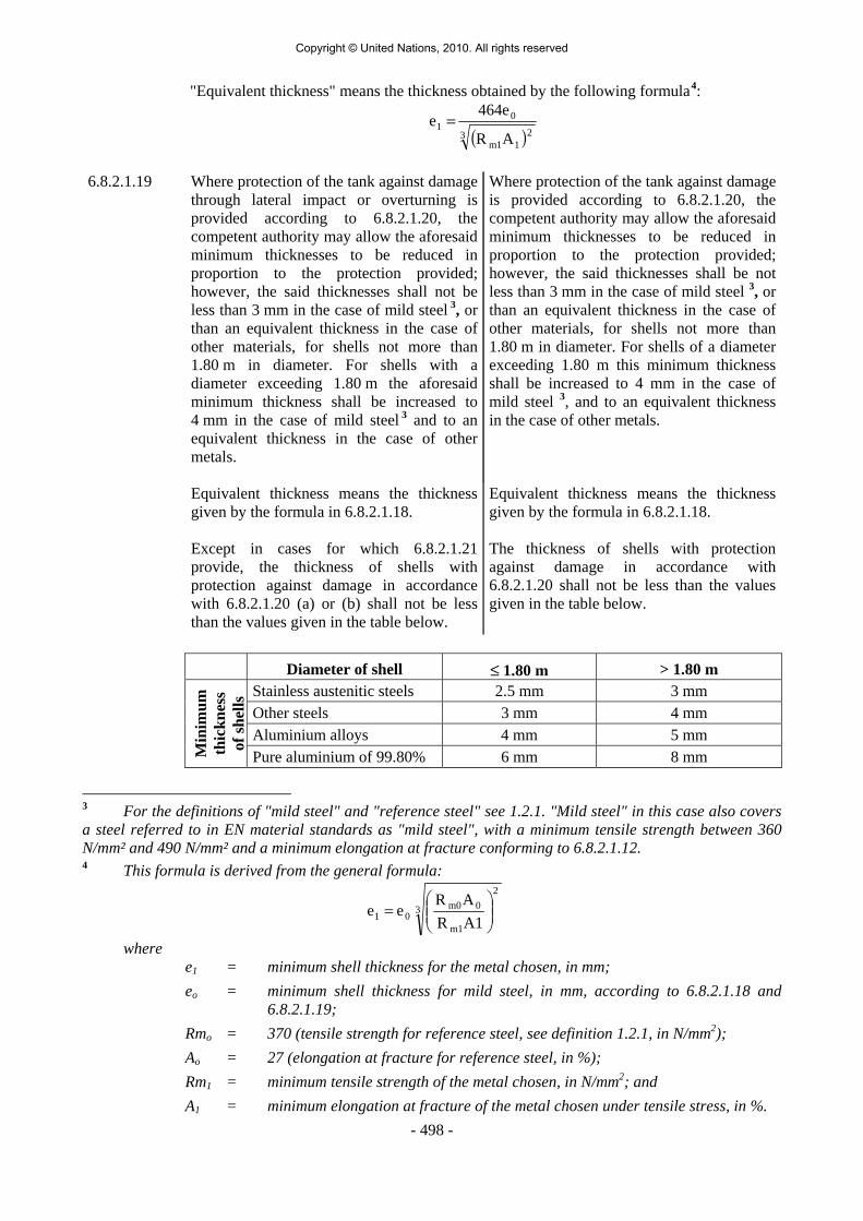
- 498 -
"Equivalent thickness" means the thickness obtained by the following formula3
4:
( )3 211m
01
AR
e464e =
6.8.2.1.19
Where protection of the tank against damage through lateral impact or overturning is provided according to 6.8.2.1.20, the competent authority may allow the aforesaid minimum thicknesses to be reduced in proportion to the protection provided; however, the said thicknesses shall not be less than 3 mm in the case of mild steel 3, or than an equivalent thickness in the case of other materials, for shells not more than 1.80 m in diameter. For shells with a diameter exceeding 1.80 m the aforesaid minimum thickness shall be increased to 4 mm in the case of mild steel 3 and to an equivalent thickness in the case of other metals.
Where protection of the tank against damage is provided according to 6.8.2.1.20, the competent authority may allow the aforesaid minimum thicknesses to be reduced in proportion to the protection provided; however, the said thicknesses shall be not less than 3 mm in the case of mild steel 3, or than an equivalent thickness in the case of other materials, for shells not more than 1.80 m in diameter. For shells of a diameter exceeding 1.80 m this minimum thickness shall be increased to 4 mm in the case of mild steel 3, and to an equivalent thickness in the case of other metals.
Equivalent thickness means the thickness given by the formula in 6.8.2.1.18. Except in cases for which 6.8.2.1.21 provide, the thickness of shells with protection against damage in accordance with 6.8.2.1.20 (a) or (b) shall not be less than the values given in the table below.
Equivalent thickness means the thickness given by the formula in 6.8.2.1.18. The thickness of shells with protection against damage in accordance with 6.8.2.1.20 shall not be less than the values given in the table below.
Diameter of shell ≤ 1.80 m > 1.80 m
Stainless austenitic steels 2.5 mm 3 mm Other steels 3 mm 4 mm Aluminium alloys 4 mm 5 mm
Min
imum
th
ickn
ess
of sh
ells
Pure aluminium of 99.80% 6 mm 8 mm
3 For the definitions of "mild steel" and "reference steel" see 1.2.1. "Mild steel" in this case also covers a steel referred to in EN material standards as "mild steel", with a minimum tensile strength between 360 N/mm² and 490 N/mm² and a minimum elongation at fracture conforming to 6.8.2.1.12. 4 This formula is derived from the general formula:
3
2
m1
0m001 A1R
AR ee ⎟⎟
⎠
⎞⎜⎜⎝
⎛=
where e1 = minimum shell thickness for the metal chosen, in mm; eo = minimum shell thickness for mild steel, in mm, according to 6.8.2.1.18 and
6.8.2.1.19;
Rmo = 370 (tensile strength for reference steel, see definition 1.2.1, in N/mm2); Ao = 27 (elongation at fracture for reference steel, in %); Rm1 = minimum tensile strength of the metal chosen, in N/mm2; and A1 = minimum elongation at fracture of the metal chosen under tensile stress, in %.
Copyright © United Nations, 2010. All rights reserved

- 499 -
6.8.2.1.20 For tanks built after 1 January 1990, there is protection against damage as referred to in 6.8.2.1.19 when the following measures or equivalent measures are adopted:
(a) For tanks intended for the carriage of powdery or granular substances, the protection against damage shall satisfy the competent authority.
(b) For tanks intended for the carriage of other substances, there is protection against damage when:
The protection referred to in 6.8.2.1.19 may consist of: - overall external structural protection as in
"sandwich" construction where the sheathing is secured to the shell; or
- a structure in which the shell is supported by a complete skeleton including longitudinal and transverse structural members; or
- double-wall construction.
1. For shells with a circular or elliptical cross-section having a maximum radius of curvature of 2 m, the shell is equipped with strengthening members comprising partitions, surge-plates or external or internal rings, so placed that at least one of the following conditions is met:
- Distance between two adjacent
strengthening elements of not more than 1.75 m.
- Volume contained between two
partitions or surge-plates of not more than 7 500 l.
The vertical cross-section of a ring,
with the associated coupling, shall have a section modulus of at least 10 cm3.
Where the tanks are made with double walls, the space between being evacuated of air, the aggregate thickness of the outer metal wall and the shell wall shall correspond to the minimum wall thickness prescribed in 6.8.2.1.18, the thickness of the wall of the shell itself being not less than the minimum thickness prescribed in 6.8.2.1.19. Where tanks are made with double walls with an intermediate layer of solid materials at least 50 mm thick, the outer wall shall have a thickness of not less than 0.5 mm if it is made of mild steel 3 or at least 2 mm if it is made of a plastics material reinforced with glass fibre. Solid foam with an impact absorption capacity such as that, for example, of polyurethane foam, may be used as the intermediate layer of solid material.
External rings shall not have
projecting edges with a radius of less than 2.5 mm.
Partitions and surge-plates shall
conform to the requirements of 6.8.2.1.22.
The thickness of the partitions and
surge-plates shall in no case be less than that of the shell.
2. For tanks made with double walls,
the space between being evacuated of air, the aggregate thickness of the outer metal wall and the shell wall corresponds to the wall thickness prescribed in 6.8.2.1.18, and the thickness of the wall of the shell itself is not less than the minimum thickness prescribed in 6.8.2.1.19.
3 For the definitions of "mild steel" and "reference steel" see 1.2.1. "Mild steel" in this case also covers
a steel referred to in EN material standards as "mild steel", with a minimum tensile strength between 360 N/mm² and 490 N/mm² and a minimum elongation at fracture conforming to 6.8.2.1.12.
Copyright © United Nations, 2010. All rights reserved
- 500 -
3. For tanks made with double walls having an intermediate layer of solid materials at least 50 mm thick, the outer wall has a thickness of at least 0.5 mm of mild steel 3 or at least 2 mm of a plastics material reinforced with glass fibre. Solid foam (with an impact absorption capacity like that, for example, of polyurethane foam) may be used as the intermediate layer of solid material.
4. Shells of forms other than in 1, especially box-shaped shells, are provided, all round the mid-point of their vertical height and over at least 30% of their height with a protection designed in such a way as to offer specific resilience at least equal to that of a shell constructed in mild steel 3 of a thickness of 5 mm (for a shell diameter not exceeding 1.80 m) or 6 mm (for a shell diameter exceeding 1.80 m). The protection shall be applied in a durable manner to the shell.
This requirement shall be considered to have been met without further proof of the specific resilience when the protection involves the welding of a plate of the same material as the shell to the area to be strengthened, so that the minimum wall thickness is in accordance with 6.8.2.1.18.
This protection is dependent upon the possible stresses exerted on mild steel 3 shells in the event of an accident, where the ends and walls have a thickness of at least 5 mm for a diameter not exceeding 1.80 m or at least 6 mm for a diameter exceeding 1.80 m. If another metal is used, the equivalent thickness shall be obtained in accordance with the formula in 6.8.2.1.18.
For demountable tanks this protection is not required when they are protected on all sides by the drop sides of the carrying vehicle.
3 For the definitions of "mild steel" and "reference steel" see 1.2.1. "Mild steel" in this case also covers
a steel referred to in EN material standards as "mild steel", with a minimum tensile strength between 360 N/mm² and 490 N/mm² and a minimum elongation at fracture conforming to 6.8.2.1.12.
Copyright © United Nations, 2010. All rights reserved
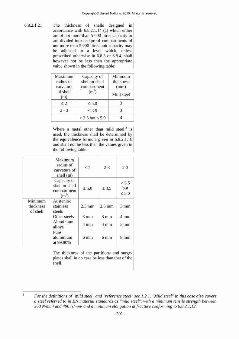
- 501 -
6.8.2.1.21 The thickness of shells designed in accordance with 6.8.2.1.14 (a) which either are of not more than 5 000 litres capacity or are divided into leakproof compartments of not more than 5 000 litres unit capacity may be adjusted to a level which, unless prescribed otherwise in 6.8.3 or 6.8.4, shall however not be less than the appropriate value shown in the following table:
Minimum
thickness (mm)
Maximum radius of curvature of shell
(m)
Capacity of shell or shell compartment
(m3) Mild steel
≤ 2 ≤ 5.0 3 2 - 3 ≤ 3.5 3 > 3.5 but ≤ 5.0 4
Where a metal other than mild steel 3 is
used, the thickness shall be determined by the equivalence formula given in 6.8.2.1.18 and shall not be less than the values given in the following table:
Maximum radius of
curvature of shell (m)
≤ 2 2-3 2-3
Capacity of shell or shell compartment
(m3)
≤ 5.0 ≤ 3.5 > 3.5 but
≤ 5.0
Austenitic stainless steels
2.5 mm 2.5 mm 3 mm
Other steels 3 mm 3 mm 4 mm Aluminium alloys 4 mm 4 mm 5 mm
Minimum thickness of shell
Pure aluminium at 99.80%
6 mm 6 mm 8 mm
The thickness of the partitions and surge-
plates shall in no case be less than that of the shell.
3 For the definitions of "mild steel" and "reference steel" see 1.2.1. "Mild steel" in this case also covers
a steel referred to in EN material standards as "mild steel", with a minimum tensile strength between 360 N/mm² and 490 N/mm² and a minimum elongation at fracture conforming to 6.8.2.1.12.
Copyright © United Nations, 2010. All rights reserved
- 502 -
6.8.2.1.22 Surge-plates and partitions shall be dished, with a depth of dish of not less than 10 cm, or shall be corrugated, profiled or otherwise reinforced to give equivalent strength. The area of the surge plate shall be at least 70% of the cross-sectional area of the tank in which the surge-plate is fitted.
Welding and inspection of welds
6.8.2.1.23 The manufacturer's qualification for performing welding operations shall be one recognized by the competent authority. Welding shall be performed by skilled welders using a welding process whose effectiveness (including any heat treatments required) has been demonstrated by test. Non-destructive tests shall be carried out by radiography or by ultrasound and must confirm that the quality of the welding is appropriate to the stresses.
The following checks shall be carried out in accordance with the value of the coefficient λ
used in determining the thickness of the shell in 6.8.2.1.17: λ = 0.8: the weld beads shall so far as possible be inspected visually on both faces
and shall be subjected to a non-destructive spot check. All weld "Tee" junctions with the total length of weld examined to be not less than 10% of the sum of the length of all longitudinal, circumferential and radial (in the tank ends) welds shall be tested;
λ = 0.9: all longitudinal beads throughout their length, all connections, 25% of circular beads, and welds for the assembly of large-diameter items of equipment shall be subjected to non-destructive checks. Beads shall be checked visually on both sides as far as possible;
λ = 1: all beads shall be subjected to non-destructive checks and shall so far as possible be inspected visually on both sides. A weld test-piece shall be taken.
Where the competent authority has doubts regarding the quality of weld beads, it may require additional checks.
Other construction requirements 6.8.2.1.24 The protective lining shall be so designed that its leakproofness remains intact, whatever the
deformation liable to occur in normal conditions of carriage (see 6.8.2.1.2). 6.8.2.1.25 The thermal insulation shall be so designed as not to hinder access to, or the operation of,
filling and discharge devices and safety valves. 6.8.2.1.26 If shells intended for the carriage of flammable liquids having a flash-point of not more
than 60 ºC are fitted with non-metallic protective linings (inner layers), the shells and the protective linings shall be so designed that no danger of ignition from electrostatic charges can occur.
Copyright © United Nations, 2010. All rights reserved

- 503 -
6.8.2.1.27 Shells intended for the carriage of liquids having a flash-point of not more than 60 ºC or for the carriage of flammable gases, or of UN No.1361 carbon or UN No.1361 carbon black, packing group II, shall be linked to the chassis by means of at least one good electrical connection. Any metal contact capable of causing electrochemical corrosion shall be avoided. Shells shall be provided with at least one earth fitting
clearly marked with the symbol " ", capable of being electrically connected.
All parts of a tank-container intended for the carriage of liquids having a flash-point of not more than 60 ºC, flammable gases, or UN No.1361 carbon or UN No.1361 carbon black, packing group II, shall be capable of being electrically earthed. Any metal contact capable of causing electrochemical corrosion shall be avoided.
6.8.2.1.28 Protection of fittings mounted on the upper part of the tank The fittings and accessories mounted on the upper part of the tank shall be protected against damage caused by overturning. This protection may take the form of strengthening rings, protective canopies or transverse or longitudinal members so shaped that effective protection is given.
6.8.2.2 Items of equipment
6.8.2.2.1 Suitable non-metallic materials may be used to manufacture service and structural equipment.
The items of equipment shall be so arranged as to be protected against the risk of being wrenched off or damaged during carriage or handling. They shall exhibit a suitable degree of safety comparable to that of the shells themselves, and shall in particular: - be compatible with the substances carried; and - meet the requirements of 6.8.2.1.1. Piping shall be designed, constructed and installed so as to avoid the risk of damage due to thermal expansion and contraction, mechanical shock and vibration.
As many operating parts as possible shall be served by the smallest possible number of openings in the shell. The leakproofness of the service equipment including the closure (cover) of the inspection openings shall be ensured even in the event of overturning of the tank, taking into account the forces generated by an impact (such as acceleration and dynamic pressure). Limited release of the tank contents due to a pressure peak during the impact is however allowed.
The leakproofness of the service equipment shall be ensured even in the event of the overturning of the tank-container.
The gaskets shall be made of a material compatible with the substance carried and shall be replaced as soon as their effectiveness is impaired, for example as a result of ageing.
Gaskets ensuring the leakproofness of fittings requiring manipulation during normal use of tanks shall be so designed and arranged that manipulation of the fittings incorporating them does not damage them.
Copyright © United Nations, 2010. All rights reserved

- 504 -
6.8.2.2.2
Each bottom-filling or bottom-discharge opening in tanks which are referred to, in Column (12) of Table A of Chapter 3.2, with a tank code including the letter "A" in its third part (see 4.3.4.1.1) shall be equipped with at least two mutually independent closures, mounted in series, comprising - an external stop-valve with piping made of a malleable metal material and - a closing device at the end of each pipe which may be a screw-threaded plug, a blank
flange or an equivalent device. This closing device shall be sufficiently tight so that the substance is contained without loss. Measures shall be taken to enable the safe release of pressure in the discharge pipe before the closing device is completely removed.
Each bottom-filling or bottom-discharge opening in tanks which are referred to, in Column (12) of Table A of Chapter 3.2, with a tank code including the letter "B" in its third part (see 4.3.3.1.1 or 4.3.4.1.1) shall be equipped with at least three mutually independent closures, mounted in series, comprising - an internal stop-valve, i.e. a stop-valve mounted inside the shell or in a welded flange
or companion flange; - an external stop-valve or an equivalent device 5
one at the end of each pipe as near as possible to the shell
and
- a closing device at the end of each pipe which may be a screw-threaded plug, a blankflange or an equivalent device. This closing device shall be sufficiently tight so thatthe substance is contained without loss. Measures shall be taken to enable the saferelease of pressure in the discharge pipe before the closing device is completelyremoved.
However, in the case of tanks intended for the carriage of certain crystallizable or highly
viscous substances and shells fitted with an ebonite or thermoplastic coating, the internalstop-valve may be replaced by an external stop-valve provided with additional protection.
The internal stop-valve shall be operable either from above or from below. Its setting - openor closed - shall so far as possible in each case be capable of being verified from the ground.Internal stop-valve control devices shall be so designed as to prevent any unintendedopening through impact or an inadvertent act.
The internal shut-off device shall continue to be effective in the event of damage to theexternal control device.
In order to avoid any loss of contents in the event of damage to the external fittings (pipes,lateral shut-off devices), the internal stop-valve and its seating shall be protected against thedanger of being wrenched off by external stresses or shall be so designed as to resist them.The filling and discharge devices (including flanges or threaded plugs) and protective caps(if any) shall be capable of being secured against any unintended opening.
The position and/or direction of closure of shut-off devices shall be clearly apparent.
All openings of tanks which are referred to in Column (12) of Table A of Chapter 3.2, by atank code including letter "C" or "D" in its third part (see 4.3.3.1.1 and 4.3.4.1.1) shall be
5 In the case of tank-containers of less than 1 m3 capacity, the external stop-valve or other equivalent device may be replaced by a blank flange.
Copyright © United Nations, 2010. All rights reserved

- 505 -
situated above the surface level of the liquid. These tanks shall have no pipes or pipeconnections below the surface level of the liquid. The cleaning openings (fist-holes) are,however, permitted in the lower part of the shell for tanks referred to by a tank codeincluding letter "C" in its third part. This opening shall be capable of being sealed by aflange so closed as to be leakproof and whose design shall be approved by the competentauthority or by a body designated by that authority.
6.8.2.2.3 Tanks that are not hermetically closed may be fitted with vacuum valves to avoid an
unacceptable negative internal pressure; these vacuum-relief valves shall be set to relieve at avacuum setting not greater than the vacuum pressure for which the tank has been designed(see 6.8.2.1.7). Hermetically closed tanks shall not be fitted with vacuum valves. However,tanks of the tank code SGAH, S4AH or L4BH, fitted with vacuum valves which open at anegative pressure of not less than 21 kPa (0.21 bar) shall be considered as being hermeticallyclosed. For tanks intended for the carriage of solid substances (powdery or granular) ofpacking groups II or III only, which do not liquefy during transport, the negative pressuremay be reduced to not less than 5 kPa (0.05 bar). Vacuum valves and venting systems (see 6.8.2.2.6) used on tanks intended for the carriage ofsubstances meeting the flash-point criteria of Class 3, shall prevent the immediate passage offlame into the tank by means of a suitable device to prevent the propagation of a flame, orthe shell of the tank shall be capable of withstanding, without leakage, an explosion resultingfrom the passage of the flame. If the protection consists of a suitable flame trap or flame arrester, it shall be positioned asclose as possible to the shell or the shell compartment. For multi-compartment tanks, eachcompartment shall be protected separately.
6.8.2.2.4 The shell or each of its compartments shall be provided with an opening large enough to
permit inspection. 6.8.2.2.5 (Reserved)
6.8.2.2.6 Tanks intended for the carriage of liquids having a vapour pressure of not more than 110 kPa
(1.1 bar) (absolute) at 50 oC shall have a venting system and a safety device to prevent thecontents from spilling out if the tank overturns; otherwise they shall conform to 6.8.2.2.7or 6.8.2.2.8.
6.8.2.2.7 Tanks intended for the carriage of liquids having a vapour pressure of more than 110 kPa
(1.1 bar) at 50 °C and a boiling point of more than 35 °C shall have a safety valve set at notless than 150 kPa (1.5 bar) (gauge pressure) and which shall be fully open at a pressure notexceeding the test pressure; otherwise they shall conform to 6.8.2.2.8.
6.8.2.2.8 Tanks intended for the carriage of liquids having a boiling point of not more than 35 °C shall
have a safety valve set at not less than 300 kPa (3 bar) gauge pressure and which shall befully open at a pressure not exceeding the test pressure; otherwise they shall be hermeticallyclosed 6.
6.8.2.2.9 Movable parts such as covers, closures, etc., which are liable to come into frictional or
percussive contact with aluminium shells intended for the carriage of flammable liquidshaving a flash-point of not more than 60 ºC or for the carriage of flammable gases shall notbe made of unprotected corrodible steel.
6 For the definition of "hermetically closed tank" see 1.2.1.
Copyright © United Nations, 2010. All rights reserved

- 506 -
6.8.2.2.10 If tanks required to be hermetically closed are equipped with safety valves, these shall be preceded by a bursting disc and the following conditions shall be observed:
The arrangement of the bursting disc and safety valve shall be such as to satisfy the
competent authority. A pressure gauge or another suitable indicator shall be provided in thespace between the bursting disc and the safety valve, to enable detection of any rupture,perforation or leakage of the disc which may disrupt the action of the safety valve.
6.8.2.3
Type approval
6.8.2.3.1 The competent authority or a body designated by that authority shall issue in respect of eachnew type of tank-vehicle, demountable tank, tank-container, tank swap body, battery-vehicle or MEGC a certificate attesting that the type, including fastenings, which it hasinspected is suitable for the purpose for which it is intended and meets the constructionrequirements of 6.8.2.1, the equipment requirements of 6.8.2.2 and the special conditionsfor the classes of substances carried. The certificate shall show:
- the results of the test;
- an approval number for the type;
The approval number shall consist of the distinguishing sign 7 of the State in whose territory the approval was granted and a registration number.
- the tank code in accordance with 4.3.3.1.1 or 4.3.4.1.1; - the alphanumerical codes of special provisions of construction (TC), equipment (TE)
and type approval (TA) of 6.8.4 which are shown in column (13) of Table A of Chapter 3.2 for those substances for the carriage of which the tank has been approved;
- if required, the substances and/or group of substances for the carriage of which the
tank has been approved. These shall be shown with their chemical name or the corresponding collective entry (see 2.1.1.2), together with their classification (class, classification code and packing group). With the exception of substances of Class 2 and those listed in 4.3.4.1.3, the listing of approved substances may be dispensed with. In such cases, groups of substances permitted on the basis of the tank code shown in the rationalised approach in 4.3.4.1.2 shall be accepted for carriage taking into account any relevant special provision.
The substances referred to in the certificate or the groups of substances approved according to the rationalised approach shall, in general, be compatible with the characteristics of the tank. A reservation shall be included in the certificate if it was not possible to investigate this compatibility exhaustively when the type approval was issued. A copy of the certificate shall be attached to the tank record of each tank, battery-vehicle or MEGC constructed (see 4.3.2.1.7).
7 Distinguishing sign for use in international traffic prescribed by the Convention on Road Traffic (Vienna, 1968).
Copyright © United Nations, 2010. All rights reserved
- 507 -
6.8.2.3.2 If the tanks, battery-vehicles or MECGs are manufactured in series without modification this approval shall be valid for the tanks, battery-vehicles or MECGs manufactured in series or according to the prototype.
A type approval may however serve for the approval of tanks with limited variations of the
design that either reduce the loads and stresses on the tanks (e.g. reduced pressure, reduced mass, reduced volume) or increase the safety of the structure (e.g. increased shell thickness, more surge-plates, decreased diameter of openings). The limited variations shall be clearly described in the type approval certificate.
6.8.2.3.3 The following requirements apply to tanks for which special provision TA4 of 6.8.4 (and therefore 1.8.7.2.4) does not apply.
The type approval shall be valid for a maximum of ten years. If within that period the relevant technical requirements of ADR (including referenced standards) have changed so that the approved type is no longer in conformity with them, the competent authority or the body designated by that authority which issued the type approval shall withdraw it and inform the holder of the type approval.
NOTE: For the ultimate dates for withdrawal of existing type approvals, see column (5) of the tables in 6.8.2.6 or 6.8.3.6 as appropriate.
If a type approval has expired or has been withdrawn, the manufacture of the tanks, battery-vehicles or MEGCs according to that type approval is no longer authorised.
In such a case, the relevant provisions concerning the use, periodic inspection and intermediate inspection of tanks, battery-vehicles or MEGCs contained in the type approval which has expired or has been withdrawn shall continue to apply to these tanks, battery-vehicles or MEGCs constructed before the expiry or the withdrawal if they may continue to be used.
They may continue to be used as long as they remain in conformity with the requirements of ADR. If they are no longer in conformity with the requirements of ADR they may continue to be used only if such use is permitted by relevant transitional measures in Chapter 1.6.
Type approvals may be renewed by a complete review and assessment for conformity with the provisions of ADR applicable at the date of renewal. Renewal is not permitted after a type approval has been withdrawn. Interim amendments of an existing type approval not affecting conformity (see 6.8.2.3.2) do not extend or modify the original validity of the certificate.
NOTE: The review and assessment of conformity can be done by a body other than the one which issued the original type approval.
The issuing body shall keep all documents for the type approval for the whole period of validity including its renewals if granted.
If the designation of the issuing body is revoked or restricted, or when the body has ceased activity, the competent authority shall take appropriate steps to ensure that the files are either processed by another body or kept available.
Copyright © United Nations, 2010. All rights reserved

- 508 -
6.8.2.4 Inspections and tests
6.8.2.4.1 Shells and their equipment shall either together or separately undergo an initial inspection before being put into service. This inspection shall include:
- a check of conformity to the approved type;
- a check of the design characteristics 8
- an examination of the internal and external conditions;
- a hydraulic pressure test 9 at the test pressure indicated on the plate prescribed in 6.8.2.5.1; and
- a leakproofness test and a check of satisfactory operation of the equipment.
Except in the case of Class 2, the test pressure for the hydraulic pressure test depends on the calculation pressure and shall be at least equal to the pressure indicated below:
Calculation pressure (bar) Test pressure (bar) G 10 G 10 1.5 1.5
2.65 2.65 4 4
10 4 15 4 21 10 (4 11)
The minimum test pressures for Class 2 are given in the table of gases and gas mixtures in 4.3.3.2.5. The hydraulic pressure test shall be carried out on the shell as a whole and separately on each compartment of compartmented shells.
The test shall be carried out on each compartment at a pressure at least equal to 1.3 times the maximum working pressure.
The hydraulic pressure test shall be carried out before the installation of a thermal insulation as may be necessary. If the shells and their equipment are tested separately, they shall be jointly subjected to a leakproofness test after assembly in accordance with 6.8.2.4.3.
The leakproofness test shall be carried out separately on each compartment of compartmented shells.
8 The check of the design characteristics shall also include, for shells requiring a test pressure of 1 MPa (10 bar) or higher, the taking of weld test-pieces (work samples) in accordance with 6.8.2.1.23 and the tests prescribed in 6.8.5. 9 In special cases and with the agreement of the expert approved by the competent authority, the hydraulic pressure test may be replaced by a pressure test using another liquid or gas, where such an operation does not present any danger. 10 G = minimum calculation pressure according to the general requirements of 6.8.2.1.14 (see 4.3.4.1). 11 Minimum test pressure for UN No. 1744 bromine or UN No. 1744 bromine solution.
Copyright © United Nations, 2010. All rights reserved

- 509 -
6.8.2.4.2 Shells and their equipment shall undergo periodic inspections no later than every
six years. five years. These periodic inspections shall include: - An external and internal examination; - A leakproofness test in accordance with 6.8.2.4.3 of the shell with its equipment and
check of the satisfactory operation of all the equipment; - As a general rule, a hydraulic pressure test 9 (for the test pressure for the shells and
compartments if applicable, see 6.8.2.4.1). Sheathing for thermal or other insulation shall be removed only to the extent required for
reliable appraisal of the characteristics of the shell. In the case of tanks intended for the carriage of powdery or granular substances, and with the
agreement of the expert approved by the competent authority, the periodic hydraulic pressure tests may be omitted and replaced by leakproofness tests in accordance with 6.8.2.4.3, at an effective internal pressure at least equal to the maximum working pressure.
6.8.2.4.3 Shells and their equipment shall undergo intermediate inspections at least every
three years two and a half years after the initial inspection and each periodic inspection. These intermediate inspections may
be performed within three months before or after the specified date. However, the intermediate inspection may be performed at any time before the specified
date. If an intermediate inspection is performed more than three months before the due date,
another intermediate inspection shall be performed at the latest
three years two and a half years after this date. These intermediate inspections shall include a leakproofness test of the shell with its
equipment and check of the satisfactory operation of all the equipment. For this purpose the tank shall be subjected to an effective internal pressure at least equal to the maximum working pressure. For tanks intended for the carriage of liquids or solids in the granular or powdery state, when a gas is used for the leakproofness test it shall be carried out at a pressure at least equal to 25% of the maximum working pressure. In all cases, it shall not be less than 20 kPa (0.2 bar) (gauge pressure).
For tanks equipped with venting systems and a safety device to prevent the contents spilling
out if the tank overturns, the pressure test shall be equal to the static pressure of the filling substance.
The leakproofness test shall be carried out separately on each compartment of
compartmented shells. 9 In special cases and with the agreement of the expert approved by the competent authority, the hydraulic pressure test may be replaced by a pressure test using another liquid or gas, where such an operation does not present any danger.
Copyright © United Nations, 2010. All rights reserved

- 510 -
6.8.2.4.4 When the safety of the tank or of its equipment may have been impaired as a result of repairs, alterations or accident, an exceptional check shall be carried out. If an exceptional check fulfilling the requirements of 6.8.2.4.2 has been performed, then the exceptional check may be considered to be a periodic inspection. If an exceptional check fulfilling the requirements of 6.8.2.4.3 has been performed then the exceptional check may be considered to be an intermediate inspection.
6.8.2.4.5 The tests, inspections and checks in accordance with 6.8.2.4.1 to 6.8.2.4.4 shall be carried
out by the expert approved by the competent authority. Certificates shall be issued showing the results of these operations, even in the case of negative results. These certificates shall refer to the list of the substances permitted for carriage in this tank or to the tank code and the alphanumeric codes of special provisions in accordance with 6.8.2.3. A copy of these certificates shall be attached to the tank record of each tank, battery-vehicle or MEGC tested (see 4.3.2.1.7).
6.8.2.5 Marking 6.8.2.5.1 Every tank shall be fitted with a corrosion-resistant metal plate permanently attached to the
tank in a place readily accessible for inspection. The following particulars at least shall be marked on the plate by stamping or by any other similar method. These particulars may be engraved directly on the walls of the shell itself, if the walls are so reinforced that the strength of the shell is not impaired 12:
- approval number;
- manufacturer’s name or mark;
- manufacturer’s serial number;
- year of manufacture;
- test pressure (gauge pressure);
- external design pressure (see 6.8.2.1.7);
- capacity of the shell – in the case of multiple-compartment shells, the capacity of each compartment –, followed by the symbol "S" when the shells or the compartments of more than 7 500 litres are divided by surge plates into sections of not more than 7 500 litres capacity;
- design temperature (only if above +50 ºC or below -20 ºC);
- date and type of the most recent test: "month, year" followed by a "P" when the test is the initial test or a periodic test in accordance with 6.8.2.4.1 and 6.8.2.4.2, or "month, year" followed by an "L" when the test is an intermediate leakproofness test in accordance with 6.8.2.4.3;
- stamp of the expert who carried out the tests;
- material of the shell and reference to materials standards, if available and, where appropriate, the protective lining;
- test pressure on the shell as a whole and test pressure by compartment in MPa or bar (gauge pressure) where the pressure by compartment is less than the pressure on the shell.
12 Add the units of measurement after the numerical values.
Copyright © United Nations, 2010. All rights reserved

- 511 -
In addition, the maximum working pressure allowed shall be inscribed on pressure-filled or pressure-discharge tanks.
6.8.2.5.2 The following particulars shall be inscribed
on the tank-vehicle itself or on a plate 12:
- name of owner or operator;
- unladen mass; and
- maximum permissible mass.
These particulars shall not be required in the case of a vehicle carrying demountable tanks. The tank code according to 4.3.4.1.1 shall be inscribed on the demountable tank itself or on a plate.
The following particulars shall be inscribed either on the tank-container itself or on a plate 12:
- names of owner and of operator;
- capacity of the shell;
- tare;
- maximum permissible laden mass;
- for the substances according to 4.3.4.1.3, the proper shipping name of the substance(s) accepted for carriage;
- tank code according to 4.3.4.1.1;
- for substances other than those according to 4.3.4.1.3, the alphanumeric codes of all special provisions TC and TE which are shown in column (13) of Table A of Chapter 3.2 for the substances to be carried in the tank.
6.8.2.6 Requirements for tanks which are designed, constructed and tested according to
referenced standards NOTE: Persons or bodies identified in standards as having responsibilities in accordance
with ADR shall meet the requirements of ADR. 6.8.2.6.1 Design and construction The standards referenced in the table below shall be applied for the issue of type approvals
as indicated in column (4) to meet the requirements of Chapter 6.8 referred to in column (3). The requirements of Chapter 6.8 referred to in column (3) shall prevail in all cases. Column (5) gives the latest date when existing type approvals shall be withdrawn according to 1.8.7.2.4 or 6.8.2.3.3; if no date is shown the type approval remains valid until it expires.
Since 1 January 2009 the use of the referenced standards has been mandatory. Exceptions are
dealt with in 6.8.2.7 and 6.8.3.7. If more than one standard is referenced for the application of the same requirements, only
one of them shall be applied, but in full unless otherwise specified in the table below.
12 Add the units of measurement after the numerical values.
Copyright © United Nations, 2010. All rights reserved

- 512 -
Reference Title of document Applicable sub-
sections and paragraphs
Applicable for new type
approvals or for renewals
Latest date for withdrawal of existing type
approvals (1) (2) (3) (4) (5)
For all tanks EN 14025:2003 + AC:2005
Tanks for the transport of dangerous goods – Metallic pressure tanks – Design and construction
6.8.2.1 Between 1 January 2005 and
30 June 2009
EN 14025:2008 Tanks for the transport of dangerous goods – Metallic pressure tanks – Design and construction
6.8.2.1 and 6.8.3.1 Until further notice
EN 14432:2006 Tanks for the transport of dangerous goods – Tank equipment for the transport of liquid chemicals – Product discharge and air inlet valves
6.8.2.2.1 Until further
notice
EN 14433:2006 Tanks for the transport of dangerous goods – Tank equipment for the transport of liquid chemicals – Foot valves
6.8.2.2.1 Until further notice
For tanks with a maximum working pressure not exceeding 50 kPa and intended for the carriage of substances for which a tank code with the letter "G" is given in column (12) of Table A of Chapter 3.2 EN 13094:2004 Tanks for the transport of dangerous goods –
Metallic tanks with a working pressure not exceeding 0.5 bar – Design and construction
6.8.2.1 Between 1 January 2005 and
31 December 2009
EN 13094:2008 + AC:2008
Tanks for the transport of dangerous goods – Metallic tanks with a working pressure not exceeding 0.5 bar – Design and construction
6.8.2.1 Until further notice
For tanks for gases of Class 2 EN 12493:2001 (except Annex C)
Welded steel tanks for liquefied petroleum gas (LPG) – Road tankers – Design and manufacture NOTE: Road tankers is to be understood in the meaning of "fixed tanks" and "demountable tanks" as per ADR.
6.8.2.1(with the exception of 6.8.2.1.17); 6.8.2.4.1 (with the exclusion of the leakproofness test); 6.8.2.5.1, 6.8.3.1 and 6.8.3.5.1
Between 1 January 2005
and 31 December 2010
31 December 2012
EN 12493:2008 (except Annex C)
LPG equipment and accessories - Welded steel tanks for liquefied petroleum gas (LPG) – Road tankers – Design and manufacture NOTE: Road tankers is to be understood in the meaning of "fixed tanks" and "demountable tanks" as per ADR.
1.2.1, 6.8.1 6.8.2.1 (with the exception of 6.8.2.1.17), 6.8.2.5, 6.8.3.1, 6.8.3.5, 6.8.5.1 to 6.8.5.3
Until further notice
EN 12252:2000 Equipping of LPG road tankers NOTE: Road tankers is to be understood in the meaning of "fixed tanks" and "demountable tanks" as per ADR.
6.8.3.2 (with the exception of 6.8.3.2.3)
Between 1 January 2005
and 31 December 2010
31 December 2012
EN 12252:2005 + A1:2008
LPG equipment and accessories – Equipping of LPG road tankers NOTE: Road tankers is to be understood in the meaning of "fixed tanks" and "demountable tanks" as per ADR.
6.8.3.2 (with the exception of 6.8.3.2.3) and 6.8.3.4.9
Until further notice
EN 13530-2:2002 Cryogenic vessels – Large transportable vacuum insulated vessels – Part 2: Design, fabrication, inspection and testing
6.8.2.1 (with the exception of 6.8.2.1.17), 6.8.2.4, 6.8.3.1 and 6.8.3.4
Between 1 January 2005
and 30 June 2007
EN 13530-2:2002 + A1:2004
Cryogenic vessels – Large transportable vacuum insulated vessels – Part 2: Design, fabrication, inspection and testing
6.8.2.1 (with the exception of 6.8.2.1.17), 6.8.2.4, 6.8.3.1 and 6.8.3.4
Until further notice
EN 14398-2:2003 (except Table 1)
Cryogenic vessels - Large transportable non-vacuum insulated vessels - Part 2: Design, fabrication, inspection and testing
6.8.2.1 (with the exception of 6.8.2.1.17, 6.8.2.1.19 and 6.8.2.1.20), 6.8.2.4, 6.8.3.1 and 6.8.3.4
Until further notice
Copyright © United Nations, 2010. All rights reserved
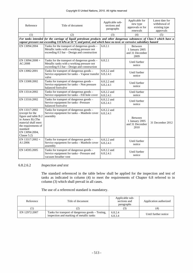
- 513 -
Reference Title of document Applicable sub-
sections and paragraphs
Applicable for new type
approvals or for renewals
Latest date for withdrawal of existing type
approvals (1) (2) (3) (4) (5)
For tanks intended for the carriage of liquid petroleum products and other dangerous substances of Class 3 which have a vapour pressure not exceeding 110 kPa at 50 °C and petrol, and which have no toxic or corrosive subsidiary hazard EN 13094:2004 Tanks for the transport of dangerous goods –
Metallic tanks with a working pressure not exceeding 0.5 bar – Design and construction
6.8.2.1 Between 1 January 2005
and 31 December 2009
EN 13094:2008 + AC:2008
Tanks for the transport of dangerous goods – Metallic tanks with a working pressure not exceeding 0.5 bar – Design and construction
6.8.2.1 Until further notice
EN 13082:2001 Tanks for transport of dangerous goods – Service equipment for tanks – Vapour transfer valve
6.8.2.2 and 6.8.2.4.1 Until further
notice
EN 13308:2002 Tanks for transport of dangerous goods – Service equipment for tanks – Non pressure balanced footvalve
6.8.2.2 and 6.8.2.4.1 Until further
notice
EN 13314:2002 Tanks for transport of dangerous goods – Service equipment for tanks – Fill hole cover
6.8.2.2 and 6.8.2.4.1
Until further notice
EN 13316:2002 Tanks for transport of dangerous goods – Service equipment for tanks –Pressure balanced footvalve
6.8.2.2 and 6.8.2.4.1 Until further
notice
EN 13317:2002 (except for the figure and table B.2 in Annex B) (The material shall meet the requirements of standard EN 13094:2004, Clause 5.2)
Tanks for transport of dangerous goods – Service equipment for tanks – Manhole cover assembly
6.8.2.2 and 6.8.2.4.1
Between 1 January 2005
and 31 December 2010
31 December 2012
EN 13317:2002 + A1:2006
Tanks for transport of dangerous goods – Service equipment for tanks – Manhole cover assembly
6.8.2.2 and 6.8.2.4.1 Until further
notice
EN 14595:2005 Tanks for transport of dangerous goods - Service equipment for tanks - Pressure and vacuum breather vent
6.8.2.2 and 6.8.2.4.1 Until further
notice
6.8.2.6.2 Inspection and test The standard referenced in the table below shall be applied for the inspection and test of
tanks as indicated in column (4) to meet the requirements of Chapter 6.8 referred to in column (3) which shall prevail in all cases.
The use of a referenced standard is mandatory.
Reference Title of document Applicable sub-
sections and paragraphs
Application authorized
(1) (2) (3) (4) EN 12972:2007 Tanks for transport of dangerous goods – Testing,
inspection and marking of metallic tanks 6.8.2.4 6.8.3.4 Until further notice
Copyright © United Nations, 2010. All rights reserved

- 514 -
6.8.2.7 Requirements for tanks which are not designed, constructed and tested according to referenced standards
To reflect scientific and technical progress or where no standard is referenced in 6.8.2.6 or to
deal with specific aspects not addressed in a standard referenced in 6.8.2.6, the competent authority may recognize the use of a technical code providing the same level of safety. Tanks shall, however, comply with the minimum requirements of 6.8.2.
The competent authority shall transmit to the secretariat of UNECE a list of the technical
codes that it recognises. The list should include the following details: name and date of the code, purpose of the code and details of where it may be obtained. The secretariat shall make this information publicly available on its website.
A standard which has been adopted for reference in a future edition of the ADR may be
approved by the competent authority for use without notifying the UNECE secretariat. For testing, inspection and marking, the applicable standard referenced in 6.8.2.6 may also
be used.
6.8.3 Special requirements applicable to Class 2 6.8.3.1 Construction of shells 6.8.3.1.1 Shells intended for the carriage of compressed or liquefied gases or dissolved gases shall be
made of steel. In the case of weldless shells, by derogation from 6.8.2.1.12 a minimum elongation at fracture of 14% and also a stress σ lower than or equal to limits hereafter given according to the material may be accepted:
(a) When the ratio Re/Rm (of the minimum guaranteed characteristics after heat
treatment) is higher than 0.66 without exceeding 0.85:
σ ≤ 0.75 Re;
(b) When the ratio Re/Rm (of the minimum guaranteed characteristics after heat treatment) is higher than 0.85:
σ ≤ 0.5 Rm.
6.8.3.1.2 The requirements of 6.8.5 apply to the materials and construction of welded shells. 6.8.3.1.3 (Reserved)
Construction of battery-vehicles and MEGCs 6.8.3.1.4 Cylinders, tubes, pressure drums and bundles of cylinders, as elements of a battery-vehicle
or MEGC, shall be constructed in accordance with Chapter 6.2.
NOTE 1: Bundles of cylinders which are not elements of a battery-vehicle or of a MEGC shall be subject to the requirements of Chapter 6.2.
NOTE 2: Tanks as elements of battery-vehicles and MEGCs shall be constructed in accordance with 6.8.2.1 and 6.8.3.1.
Copyright © United Nations, 2010. All rights reserved

- 515 -
NOTE 3: Demountable tanks 13 are not to be considered elements of battery-vehicles or MEGCs.
6.8.3.1.5 Elements and their fastenings shall be capable of absorbing under the maximum permissible load the forces defined in 6.8.2.1.2. Under each force the stress at the most severely stressed point of the element and its fastenings shall not exceed the value defined in 6.2.5.3 for cylinders, tubes, pressure drums and bundles of cylinders and for tanks the value of σ defined in 6.8.2.1.16.
6.8.3.2 Items of equipment 6.8.3.2.1 The discharge pipes of tanks shall be capable of being closed by blank flanges or some other
equally reliable device. For tanks intended for the carriage of refrigerated liquefied gases, these blank flanges or other equally reliable devices may be fitted with pressure-release openings of a maximum diameter of 1.5 mm.
6.8.3.2.2 Shells intended for the carriage of liquefied gases may be provided with, in addition to the
openings prescribed in 6.8.2.2.2 and 6.8.2.2.4, openings for the fitting of gauges, thermometers, manometers and with bleed holes, as required for their operation and safety.
6.8.3.2.3 The internal stop-valve of all filling and all discharge openings of tanks
with a capacity greater than 1 m3 intended for the carriage of liquefied flammable or toxic gases shall be instant-closing and
shall close automatically in the event of an unintended movement of the tank or in the event of fire. It shall also be possible to operate the internal stop-valve by remote control.
However on tanks intended for the carriage of liquefied non-toxic flammable gases, the internal stop-valve with remote control may be replaced by a non-return valve for filling openings into the vapour phase of the tank only. The non-return valve shall be positioned internally in the tank, be spring loaded so that the valve is closed if the pressure in the filling line is equal to or lower than the pressure in the tank and be equipped with appropriate sealing14.
6.8.3.2.4 All openings, other than those accommodating safety valves and closed bleed holes, of tanks
intended for the carriage of liquefied flammable and/or toxic gases shall, if their nominal diameter is more than 1.5 mm, shall be equipped with an internal shut-off device.
6.8.3.2.5 Notwithstanding the requirements of 6.8.2.2.2, 6.8.3.2.3 and 6.8.3.2.4, tanks intended for the
carriage of refrigerated liquefied gases may be equipped with external devices in place of internal devices if the external devices afford protection against external damage at least equivalent to that afforded by the wall of the shell.
6.8.3.2.6 If the tanks are equipped with gauges in direct contact with the substance carried, the gauges
shall not be made of a transparent material. If there are thermometers, they shall not project directly into the gas or liquid through the shell.
13 For the definition of "demountable tank" see 1.2.1. 14 The use of metal to metal sealing is not permitted.
Copyright © United Nations, 2010. All rights reserved

- 516 -
6.8.3.2.7 Filling and discharge openings situated in the upper part of tanks shall be equipped with, in addition to what is prescribed in 6.8.3.2.3, a second, external, closing device. This device shall be capable of being closed by a blank flange or some other equally reliable device.
6.8.3.2.8 Safety valves shall meet the requirements of 6.8.3.2.9 to 6.8.3.2.12 below: 6.8.3.2.9 Tanks intended for the carriage of compressed or liquefied gases or dissolved gases, may be
fitted with spring-loaded safety valves. These valves shall be capable of opening automatically under a pressure between 0.9 and 1.0 times the test pressure of the tank to which they are fitted. They shall be of such a type as to resist dynamic stresses, including liquid surge. The use of dead weight or counter weight valves is prohibited. The required capacity of the safety valves shall be calculated in accordance with the formula contained in 6.7.3.8.1.1.
6.8.3.2.10 Where tanks are intended for carriage by sea, the requirements of 6.8.3.2.9 shall not prohibit
the fitting of safety valves conforming to the IMDG Code. 6.8.3.2.11 Tanks intended for the carriage of refrigerated liquefied gases shall be equipped with two or
more independent safety valves capable of opening at the maximum working pressure indicated on the tank. Two of these safety valves shall be individually sized to allow the gases formed by evaporation during normal operation to escape from the tank in such a way that the pressure does not at any time exceed by more than 10% the working pressure indicated on the tank.
One of the safety valves may be replaced by a bursting disc which shall be such as to burst at
the test pressure. In the event of loss of the vacuum in a double-walled tank, or of destruction of 20% of the
insulation of a single-walled tank, the combination of the pressure relief devices shall permit an outflow such that the pressure in the shell cannot exceed the test pressure. The provisions of 6.8.2.1.7 shall not apply to vacuum-insulated tanks.
6.8.3.2.12 These pressure relief devices of tanks intended for the carriage of refrigerated liquefied gases
shall be so designed as to function faultlessly even at their lowest working temperature. The reliability of their operation at that temperature shall be established and checked either by testing each device or by testing a specimen device of each design-type.
6.8.3.2.13 The valves of demountable tanks that can be rolled shall be provided with protective caps.
Thermal insulation 6.8.3.2.14 If tanks intended for the carriage of liquefied gases are equipped with thermal insulation,
such insulation shall consist of either:
- a sun shield covering not less than the upper third but not more than the upper half of the tank surface and separated from the shell by an air space at least 4 cm across; or
- a complete cladding, of adequate thickness, of insulating materials.
6.8.3.2.15 Tanks intended for the carriage of refrigerated liquefied gases shall be thermally insulated.
Thermal insulation shall be ensured by means of a continuous sheathing. If the space between the shell and the sheathing is under vacuum (vacuum insulation), the protective sheathing shall be so designed as to withstand without deformation an external pressure of at least 100 kPa (1 bar) (gauge pressure). By derogation from the definition of "calculation pressure" in 1.2.1, external and internal reinforcing devices may be taken into account in the
Copyright © United Nations, 2010. All rights reserved

- 517 -
calculations. If the sheathing is so closed as to be gas-tight, a device shall be provided to prevent any dangerous pressure from developing in the insulating layer in the event of inadequate gas-tightness of the shell or of its items of equipment. The device shall prevent the infiltration of moisture into the heat-insulating sheath.
6.8.3.2.16 Tanks intended for the carriage of liquefied gases having a boiling point below -182° C at
atmospheric pressure shall not include any combustible material either in the thermal insulation or in the means of attachment.
The means of attachment for vacuum insulated tanks may, with the approval of the
competent authority, contain plastics substances between the shell and the sheathing. 6.8.3.2.17 By derogation from the requirements of 6.8.2.2.4 shells intended for the carriage of
refrigerated liquefied gases need not have an inspection opening. Items of equipment for battery-vehicles and MEGCs 6.8.3.2.18 Service and structural equipment shall be configured or designed to prevent damage that
could result in the release of the pressure receptacle contents during normal conditions of handling and carriage. When the connection between the frame of the battery-vehicle or MEGC and the elements allows relative movement between the sub-assemblies, the equipment shall be so fastened as to permit such movement without damage to working parts. Manifold piping leading to shut-off valves shall be sufficiently flexible to protect the valves and the piping from shearing, or releasing the pressure receptacle contents. The filling and discharge devices (including flanges or threaded plugs) and any protective caps shall be capable of being secured against unintended opening.
6.8.3.2.19 In order to avoid any loss of content in the event of damage, the manifolds, the discharge
fittings (pipe sockets, shut-off devices), and the stop-valves shall be protected or arranged from being wrenched off by external forces or designed to withstand them.
6.8.3.2.20 The manifold shall be designed for service in a temperature range of -20° C to +50° C. The manifold shall be designed, constructed and installed so as to avoid the risk of damage
due to thermal expansion and contraction, mechanical shock and vibration. All piping shall be of suitable metallic material. Welded pipe joints shall be used wherever possible.
Joints in copper tubing shall be brazed or have an equally strong metal union. The melting
point of brazing materials shall be no lower than 525ºC. The joints shall not decrease the strength of tubing as may happen when cutting threads.
6.8.3.2.21 Except for UN No.1001 acetylene, dissolved, the permissible maximum stress σ of the manifolding arrangement at the test pressure of the receptacles shall not exceed 75% of the guaranteed yield strength of the material.
The necessary wall thickness of the manifolding arrangement for the carriage of
UN No.1001 acetylene, dissolved shall be calculated according to an approved code of practice.
NOTE: For the yield strength, see 6.8.2.1.11. The basic requirements of this paragraph shall be deemed to have been complied with if the
following standards are applied: (Reserved).
Copyright © United Nations, 2010. All rights reserved

- 518 -
6.8.3.2.22 By derogation from the requirements of 6.8.3.2.3, 6.8.3.2.4 and 6.8.3.2.7, for cylinders, tubes, pressure drums and bundles of cylinders (frames) forming a battery-vehicle or MEGC, the required closing devices may be provided for within the manifolding arrangement.
6.8.3.2.23 If one of the elements is equipped with a safety valve and shut-off devices are provided
between the elements, every element shall be so equipped. 6.8.3.2.24 The filling and discharge devices may be affixed to a manifold. 6.8.3.2.25 Each element, including each individual cylinder of a bundle, intended for the carriage of
toxic gases, shall be capable of being isolated by a shut-off valve. 6.8.3.2.26 Battery-vehicles or MEGCs intended for the carriage of toxic gases shall not have safety
valves, unless the safety valves are preceded by a bursting disc. In the latter case, the arrangement of the bursting disc and safety valve shall be satisfactory to the competent authority.
6.8.3.2.27 When battery-vehicles or MEGCs are intended for carriage by sea, the requirements of
6.8.3.2.26 shall not prohibit the fitting of safety valves conforming to the IMDG Code. 6.8.3.2.28 Receptacles which are elements of a battery-vehicle or MEGC intended for the carriage of
flammable gases shall be combined in groups of not more than 5 000 litres which are capable of being isolated by a shut-off valve.
Each element of a battery-vehicle or MEGC intended for the carriage of flammable gases,
when consisting of tanks conforming to this Chapter, shall be capable of being isolated by a shut-off valve.
6.8.3.3 Type approval No special requirements. 6.8.3.4 Inspections and tests 6.8.3.4.1 The materials of every welded shell with the exception of cylinders, tubes, pressure drums
and cylinders as part of bundles of cylinders which are elements of a battery-vehicle or of a MEGC shall be tested according to the method described in 6.8.5.
6.8.3.4.2 The basic requirements for the test pressure are given in 4.3.3.2.1 to 4.3.3.2.4 and the
minimum test pressures are given in the table of gases and gas mixtures in 4.3.3.2.5. 6.8.3.4.3 The first hydraulic pressure test shall be carried out before thermal insulation is placed in
position. When the shell, its fittings, piping and items of equipment have been tested separately, the tank shall be subjected to a leakproofness test after assembly.
6.8.3.4.4 The capacity of each shell intended for the carriage of compressed gases filled by mass,
liquefied gases or dissolved gases shall be determined, under the supervision of an expert approved by the competent authority, by weighing or volumetric measurement of the quantity of water which fills the shell; the measurement of shell capacity shall be accurate to within 1%. Determination by a calculation based on the dimensions of the shell is not permitted. The maximum filling masses allowed in accordance with packing instruction P200 or P203 in 4.1.4.1 as well as 4.3.3.2.2 and 4.3.3.2.3 shall be prescribed by an approved expert.
6.8.3.4.5 Checking of the welds shall be carried out in accordance with the λ=1 requirements
of 6.8.2.1.23.
Copyright © United Nations, 2010. All rights reserved

- 519 -
6.8.3.4.6 By derogation from the requirements of 6.8.2.4, the periodic inspections according to 6.8.2.4.2, shall take place:
(a) at least every three years at least every two and a half years
in the case of tanks intended for the carriage of UN No. 1008 boron trifluoride, UN No. 1017
chlorine, UN No. 1048 hydrogen bromide, anhydrous, UN No. 1050 hydrogen chloride, anhydrous, UN No. 1053 hydrogen sulphide or UN No. 1079 sulphur dioxide; (b) at least after six years
at least after 8 years
of service and thereafter at least every 12 years in the case of tanks intended for the carriage
of refrigerated liquefied gases.
The intermediate inspections according to 6.8.2.4.3 shall be carried out at least six years after each periodic inspection.
A leakproofness test or an intermediate inspection according to 6.8.2.4.3 may be performed, at the request of the competent authority, between any two successive periodic inspections.
When the shell, its fittings, piping and items of equipment have been tested separately, the
tank shall be subjected to a leakproofness test after assembly. 6.8.3.4.7 In the case of vacuum-insulated tanks, the hydraulic-pressure test and the check of the
internal condition may, with the consent of the approved expert, be replaced by a leakproofness test and measurement of the vacuum.
6.8.3.4.8 If, at the time of periodic inspections, openings have been made in shells intended for the
carriage of refrigerated liquefied gases, the method by which they are hermetically closed before the shells are returned to service shall be approved by the approved expert and shall ensure the integrity of the shell.
6.8.3.4.9 Leakproofness tests of tanks intended for the carriage of gases shall be performed at a
pressure of not less than:
- For compressed gases, liquefied gases and dissolved gases: 20% of the test pressure;
- For refrigerated liquefied gases: 90% of the maximum working pressure.
Inspections and tests for battery-vehicles and MEGCs 6.8.3.4.10 The elements and items of equipment of each battery-vehicle or MEGC shall be inspected
and tested either together or separately before being put into service for the first time (initial inspection and test). Thereafter battery-vehicles or MEGCs the elements of which are receptacles shall be inspected at not more than five-year intervals. Battery-vehicles and MEGCs the elements of which are tanks shall be inspected according to 6.8.3.4.6. An exceptional inspection and test shall be performed regardless of the last periodic inspection and test when necessary according to 6.8.3.4.14.
6.8.3.4.11 The initial inspection shall include:
- a check of conformity to the approved type;
- a check of the design characteristics;
- an examination of the internal and external conditions;
Copyright © United Nations, 2010. All rights reserved

- 520 -
- a hydraulic pressure test 9 at the test pressure indicated on the plate prescribed in 6.8.3.5.10;
- a leakproofness test at the maximum working pressure; and
- a check of satisfactory operation of the equipment.
When the elements and their fittings have been pressure-tested separately, they shall be subjected together after assembly to a leakproofness test.
6.8.3.4.12 Cylinders, tubes and pressure drums and cylinders as part of bundles of cylinders shall be
tested according to packing instruction P200 or P203 in 4.1.4.1. The test pressure of the manifold of the battery-vehicle or MEGC shall be the same as that of
the elements of the battery-vehicle or MEGC. The pressure test of the manifold may be performed as a hydraulic test or by using another liquid or gas with the agreement of the competent authority or its authorised body. By derogation from this requirement, the test pressure for the manifold of battery-vehicle or MEGC shall not be less than 300 bar for UN No. 1001 acetylene, dissolved.
6.8.3.4.13 The periodic inspection shall include a leakproofness test at the maximum working pressure
and an external examination of the structure, the elements and the service equipment without disassembling. The elements and the piping shall be tested at the periodicity defined in packing instruction P200 of 4.1.4.1 and in accordance with the requirements of 6.2.1.6 and 6.2.3.5 respectively. When the elements and equipment have been pressure-tested separately, they shall be subjected together after assembly to a leakproofness test.
6.8.3.4.14 An exceptional inspection and test is necessary when the battery-vehicle or MEGC shows
evidence of damaged or corroded areas, or leakage, or any other conditions, that indicate a deficiency that could affect the integrity of the battery-vehicle or MEGC. The extent of the exceptional inspection and test and, if deemed necessary, the disassembling of elements shall depend on the amount of damage or deterioration of the battery-vehicle or MEGC. It shall include at least the examinations required under 6.8.3.4.15.
6.8.3.4.15 The examinations shall ensure that:
(a) The elements are inspected externally for pitting, corrosion, or abrasions, dents,
distortions, defects in welds or any other conditions, including leakage, that might render the battery-vehicles or MEGCs unsafe for transport;
(b) The piping, valves, and gaskets are inspected for corroded areas, defects, and other
conditions, including leakage, that might render battery-vehicles or MEGCs unsafe for filling, discharge or transport;
(c) Missing or loose bolts or nuts on any flanged connection or blank flange are replaced
or tightened; (d) All emergency devices and valves are free from corrosion, distortion and any damage
or defect that could prevent their normal operation. Remote closure devices and self-closing stop-valves shall be operated to demonstrate proper operation;
(e) Required markings on the battery-vehicles or MEGCs are legible and in accordance
with the applicable requirements; and 9 In special cases and with the agreement of the expert approved by the competent authority, the hydraulic pressure test may be replaced by a pressure test using another liquid or gas, where such an operation does not present any danger.
Copyright © United Nations, 2010. All rights reserved

- 521 -
(f) Any framework, supports and arrangements for lifting the battery-vehicles or MEGCs are in satisfactory condition.
6.8.3.4.16 The tests, inspections and checks in accordance with 6.8.3.4.10 to 6.8.3.4.15 shall be carried
out by the expert approved by the competent authority. Certificates shall be issued showing the results of these operations, even in the case of negative results.
These certificates shall refer to the list of the substances permitted for carriage in this battery-vehicle or MEGC in accordance with 6.8.2.3.1. A copy of these certificates shall be attached to the tank record of each tank, battery-vehicle or MEGC tested (see 4.3.2.1.7).
6.8.3.5 Marking 6.8.3.5.1 The following additional particulars shall be marked by stamping or by any other similar
method on the plate prescribed in 6.8.2.5.1, or directly on the walls of the shell itself if the walls are so reinforced that the strength of the tank is not impaired.
6.8.3.5.2 On tanks intended for the carriage of only one substance:
- the proper shipping name of the gas and, in addition for gases classified under an n.o.s. entry, the technical name 15;
This indication shall be supplemented:
- in the case of tanks intended for the carriage of compressed gases filled by volume (pressure), by an indication of the maximum filling pressure at 15 °C permitted for the tank; and
- in the case of tanks intended for the carriage of compressed gases filled by mass, and of liquefied gases, refrigerated liquefied gases or dissolved gases by an indication of the maximum permissible load mass in kg and of the filling temperature if below –20 °C.
6.8.3.5.3 On multipurpose tanks:
- the proper shipping names of the gases and, in addition for gases classified under an n.o.s. entry, the technical name of the gases 15 for whose carriage the tank is approved.
These particulars shall be supplemented by an indication of the maximum permissible load
mass in kg for each gas. 6.8.3.5.4 On tanks intended for the carriage of refrigerated liquefied gases:
- the maximum working pressure allowed. 15 Instead of the proper shipping name or, if applicable, of the proper shipping name of the n.o.s. entry followed by the technical name, the use of the following names is permitted:
- for UN No. 1078 refrigerant gas, n.o.s: mixture F1, mixture F2, mixture F3; - for UN No. 1060 methylacetylene and propadiene mixtures, stabilized: mixture P1, mixture P2; - for UN No. 1965 hydrocarbon gas mixture, liquefied, n.o.s: mixture A, mixture A01,
mixture A02, mixture A0, mixture A1, mixture B1, mixture B2, mixture B, mixture C. The names customary in the trade and mentioned in 2.2.2.3, Classification code 2F, UN No. 1965, Note 1 may be used only as a complement;
- for UN No. 1010 Butadienes, stabilized: 1,2-Butadiene, stabilized, 1,3-Butadiene, stabilized.
Copyright © United Nations, 2010. All rights reserved

- 522 -
6.8.3.5.5 On tanks equipped with thermal insulation:
- the inscription "thermally insulated" or "thermally insulated by vacuum".
6.8.3.5.6 In addition to the particulars prescribed in 6.8.2.5.2, the following shall be inscribed on
the tank itself or on a plate: the tank-container itself or on a plate:
(a) - the tank code according to the certificate (see 6.8.2.3.1) with the actual test pressure of the tank;
- the inscription: "minimum filling temperature allowed: …";
(b) where the tank is intended for the carriage of one substance only:
-2 the proper shipping name of the gas and, in addition for gases classified under
an n.o.s. entry, the technical name 15; - for compressed gases which are filled by mass, and for liquefied gases,
refrigerated liquefied gases or dissolved gases, the maximum permissible load mass in kg;
(c) where the tank is a multipurpose tank:
- the proper shipping name of the gas and, for gases classified under an n.o.s. entry, the technical name 15 of all gases to whose carriage the tank is assigned with an indication of the maximum permissible load mass in kg for each of them;
(d) where the shell is equipped with thermal insulation:
- the inscription "thermally insulated" (or "thermally insulated by vacuum"), in an
official language of the country of registration and also, if that language is not English, French or German, in English, French or German, unless any agreements concluded between the countries concerned in the transport operation provide otherwise.
6.8.3.5.7 (Reserved) 6.8.3.5.8 These particulars shall not be required in the
case of a vehicle carrying demountable tanks.
6.8.3.5.9 (Reserved)
15 Instead of the proper shipping name or, if applicable, of the proper shipping name of the n.o.s. entry followed by the technical name, the use of the following names is permitted:
- for UN No. 1078 refrigerant gas, n.o.s: mixture F1, mixture F2, mixture F3; - for UN No. 1060 methylacetylene and propadiene mixtures, stabilized: mixture P1, mixture P2; - for UN No. 1965 hydrocarbon gas mixture, liquefied, n.o.s: mixture A, mixture A01,
mixture A02, mixture A0, mixture A1, mixture B1, mixture B2, mixture B, mixture C. The names customary in the trade and mentioned in 2.2.2.3, Classification code 2F, UN No. 1965, Note 1 may be used only as a complement;
- for UN No. 1010 Butadienes, stabilized: 1,2-Butadiene, stabilized, 1,3-Butadiene, stabilized.
Copyright © United Nations, 2010. All rights reserved

- 523 -
Marking of battery-vehicles and MEGCs 6.8.3.5.10 Every battery-vehicle and every MEGC shall be fitted with a corrosion-resistant metal plate
permanently attached in a place readily accessible for inspection. The following particulars at least shall be marked on the plate by stamping or by any other similar method 12
- approval number;
- manufacturer’s name or mark;
- manufacturer’s serial number;
- year of manufacture;
- test pressure (gauge pressure)
- design temperature (only if above +50 °C or below -20 °C);
- date (month and year) of initial test and most recent periodic test in accordance with 6.8.3.4.10 to 6.8.3.4.13;
- stamp of the expert who carried out the tests. 6.8.3.5.11 The following particulars shall be inscribed
on the battery-vehicle itself or on a plate 12:
- names of owner or of operator;
- number of elements;
- total capacity of the elements;
and for battery-vehicles filled by mass:
- unladen mass;
- maximum permissible mass.
The following particulars shall be inscribed either on the MEGC itself or on a plate 12:
- names of owner and of operator;
- number of elements;
- total capacity of the elements;
- maximum permissible laden mass;
- the tank code according to the certificate of approval (see 6.8.2.3.1) with the actual test pressure of the MEGC;
- the proper shipping name of the gases, and in addition, for gases classified under an n.o.s. entry, the technical name 15 of the gases for whose carriage the MEGC is used;
and for MEGCs filled by mass:
- tare.
12 Add the units of measurements after the numerical values. 15 Instead of the proper shipping name or, if applicable, of the proper shipping name of the n.o.s. entry followed by the technical name, the use of the following names is permitted:
- for UN No. 1078 refrigerant gas, n.o.s: mixture F1, mixture F2, mixture F3; - for UN No. 1060 methylacetylene and propadiene mixtures, stabilized: mixture P1, mixture P2; - for UN No. 1965 hydrocarbon gas mixture, liquefied, n.o.s: mixture A, mixture A01,
mixture A02, mixture A0, mixture A1, mixture B1, mixture B2, mixture B, mixture C. The names customary in the trade and mentioned in 2.2.2.3, Classification code 2F, UN No. 1965, Note 1 may be used only as a complement;
- for UN No. 1010 Butadienes, stabilized: 1,2-Butadiene, stabilized, 1,3-Butadiene, stabilized.
Copyright © United Nations, 2010. All rights reserved

- 524 -
6.8.3.5.12 The frame of a battery-vehicle or MEGC shall bear near the filling point a plate specifying:
- the maximum filling pressure 12 at 15 °C allowed for elements intended for compressed gases;
- the proper shipping name of the gas in accordance with Chapter 3.2 and, in addition
for gases classified under an n.o.s. entry, the technical name 15;
and, in addition, in the case of liquefied gases: - the permissible maximum load per element 12.
6.8.3.5.13 Cylinders, tubes and pressure drums, and cylinders as part of bundles of cylinders, shall be
marked according to 6.2.2.7. These receptacles need not be labelled individually with the danger labels as required in Chapter 5.2.
Battery-vehicles and MEGCs shall be placarded and marked according to Chapter 5.3. 6.8.3.6 Requirements for battery-vehicles and MEGCs which are designed, constructed and tested
according to referenced standards
NOTE: Persons or bodies identified in standards as having responsibilities in accordance with ADR shall meet the requirements of ADR.
The standard referenced in the table below shall be applied for the issue of type approvals as
indicated in column (4) to meet the requirements of Chapter 6.8 referred to in column (3). The requirements of Chapter 6.8 referred to in column (3) shall prevail in all cases. Column (5) gives the latest date when existing type approvals shall be withdrawn according to 1.8.7.2.4; if no date is shown the type approval remains valid until it expires.
Since 1 January 2009 the use of the referenced standards has been mandatory. Exceptions
are dealt with in 6.8.3.7 If more than one standard is referenced for the application of the same requirements, only
one of them shall be applied, but in full unless otherwise specified in the table below.
12 Add the units of measurements after the numerical values. 15 Instead of the proper shipping name or, if applicable, of the proper shipping name of the n.o.s. entry followed by the technical name, the use of the following names is permitted:
- for UN No. 1078 refrigerant gas, n.o.s: mixture F1, mixture F2, mixture F3; - for UN No. 1060 methylacetylene and propadiene mixtures, stabilized: mixture P1, mixture P2; - for UN No. 1965 hydrocarbon gas mixture, liquefied, n.o.s: mixture A, mixture A01,
mixture A02, mixture A0, mixture A1, mixture B1, mixture B2, mixture B, mixture C. The names customary in the trade and mentioned in 2.2.2.3, Classification code 2F, UN No. 1965, Note 1 may be used only as a complement;
- for UN No. 1010 Butadienes, stabilized: 1,2-Butadiene, stabilized, 1,3-Butadiene, stabilized.
Copyright © United Nations, 2010. All rights reserved

- 525 -
Reference Title of document Applicable sub-
sections and paragraphs
Applicable for new type
approvals or for renewals
Latest date for withdrawal of existing type
approvals (1) (2) (3) (4) (5)
EN 13807:2003 Transportable gas cylinders – Battery vehicles – Design, manufacture, identification and testing
6.8.3.1.4 and 6.8.3.1.5, 6.8.3.2.18 to 6.8.3.2.26, 6.8.3.4.10 to 6.8.3.4.12 and 6.8.3.5.10 to 6.8.3.5.13
Until further notice
6.8.3.7 Requirements for battery-vehicles and MEGCs which are not designed, constructed and
tested according to referenced standards To reflect scientific and technical progress or where no standard is referenced in 6.8.3.6 or to
deal with specific aspects not addressed in a standard referenced in 6.8.3.6, the competent authority may recognize the use of a technical code providing the same level of safety. Battery-vehicles and MEGCs shall, however, comply with the minimum requirements of 6.8.3.
In the type approval the issuing body shall specify the procedure for periodic inspections if
the standards referenced in 6.2.2, 6.2.4 or 6.8.2.6 are not applicable or shall not be applied. The competent authority shall transmit to the secretariat of UNECE a list of the technical
codes that it recognises. The list should include the following details: name and date of the code, purpose of the code and details of where it may be obtained. The secretariat shall make this information publicly available on its website.
A standard which has been adopted for reference in a future edition of the ADR may be
approved by the competent authority for use without notifying the UNECE secretariat. 6.8.4 Special provisions
NOTE 1: For liquids having a flash-point of not more than 60 °C and for flammable gases, see also 6.8.2.1.26, 6.8.2.1.27 and 6.8.2.2.9. NOTE 2: For requirements for tanks subjected to a pressure test of not less than 1 MPa (10 bar) or for tanks intended for the carriage of refrigerated liquefied gases, see 6.8.5.
When they are shown under an entry in Column (13) of Table A of Chapter 3.2, the
following special provisions apply:
(a) Construction (TC)
TC1 The requirements of 6.8.5 are applicable to the materials and construction of these shells.
TC2 Shells, and their items of equipment, shall be made of aluminium not less than
99.5% pure or of suitable steel not liable to cause hydrogen peroxide to decompose. Where shells are made of aluminium not less than 99.5% pure, the wall thickness need not exceed 15 mm, even where calculation in accordance with 6.8.2.1.17 gives a higher value.
TC3 The shells shall be made of austenitic steel.
Copyright © United Nations, 2010. All rights reserved

- 526 -
TC4 Shells shall be provided with an enamel or equivalent protective lining if the material of the shell is attacked by UN No. 3250 chloroacetic acid.
TC5 Shells shall be provided with a lead lining not less than 5 mm thick or an equivalent
lining. TC6 Where the use of aluminium is necessary for tanks, such tanks shall be made of
aluminium not less than 99.5% pure; the wall thickness need not exceed 15 mm even where calculation in accordance with 6.8.2.1.17 gives a higher value.
TC7 The effective minimum thickness of the shell shall not be less than 3 mm. (b) Items of equipment (TE) TE1 (Deleted) TE2 (Deleted)
TE3 Tanks shall in addition meet the following requirements. The heating device shall not penetrate into, but shall be exterior to the shell. However, a pipe used for extracting the phosphorus may be equipped with a heating jacket. The device heating the jacket shall be so regulated as to prevent the temperature of the phosphorus from exceeding the filling temperature of the shell. Other piping shall enter the shell in its upper part; openings shall be situated above the highest permissible level of the phosphorus and be capable of being completely enclosed under lockable caps. The tank shall be equipped with a gauging system for verifying the level of the phosphorus and, if water is used as a protective agent, with a fixed gauge mark showing the highest permissible level of the water.
TE4 Shells shall be equipped with thermal insulation made of materials which are not
readily flammable. TE5 If shells are equipped with thermal insulation, such insulation shall be made of
materials which are not readily flammable. TE6 Tanks may be equipped with a device of a design which precludes its obstruction by
the substance carried and which prevents leakage and the build-up of excess overpressure or underpressure inside the shell.
TE7 The shell-discharge system shall be equipped with two mutually independent shut-
off devices mounted in series, the first taking the form of a quick-closing internal stop-valve of an approved type and the second that of an external stop-valve, one at each end of the discharge pipe. A blank flange, or another device providing the same measure of security, shall also be fitted at the outlet of each external stop-valve. The internal stop-valve shall be such that if the pipe is wrenched off the stop-valve will remain integral with the shell and in the closed position.
TE8 The connections to the external pipe-sockets of tanks shall be made of materials not
liable to cause decomposition of hydrogen peroxide. TE9 Tanks shall be fitted in their upper part with a shut-off device preventing any build-
up of excess pressure inside the shell due to the decomposition of the substances carried, any leakage of liquid, and any entry of foreign matter into the shell.
Copyright © United Nations, 2010. All rights reserved

- 527 -
TE10 The shut-off devices of tanks shall be so designed as to preclude obstruction of the devices by the solidified substance during carriage. Where tanks are sheathed in thermally-insulating material, the material shall be of an inorganic nature and entirely free from combustible matter.
TE11 Shells and their service equipment shall be so designed as to prevent the entry of
foreign matter, leakage of liquid or any building up of dangerous excess pressure inside the shell due to the decomposition of the substances carried. A safety valve preventing the entry of foreign matter also fulfils this provision.
TE12 Tanks shall be equipped with thermal insulation complying with the requirements of 6.8.3.2.14. If the SADT of the organic peroxide in the tank is 55 °C or less, or the tank is constructed of aluminium, the shell shall be completely insulated. The sun shield and any part of the tank not covered by it, or the outer sheathing of a complete lagging, shall be painted white or finished in bright metal. The paint shall be cleaned before each transport journey and renewed in case of yellowing or deterioration. The thermal insulation shall be free from combustible matter. Tanks shall be fitted with temperature sensing devices.
Tanks shall be fitted with safety valves and emergency pressure-relief devices.
Vacuum-relief devices may also be used. Emergency pressure-relief devices shall operate at pressures determined according to both the properties of the organic peroxide and the construction characteristics of the tank. Fusible elements shall not be permitted in the body of the shell.
Tanks shall be fitted with spring-loaded safety valves to prevent significant pressure
build-up within the shell of the decomposition products and vapours released at a temperature of 50 °C. The capacity and start-to-discharge pressure of the safety-valve(s) shall be based on the results of the tests specified in special provision TA2. The start-to-discharge pressure shall however in no case be such that liquid could escape from the valve(s) if the tank were overturned.
The emergency-relief devices may be of the spring-loaded or frangible types
designed to vent all the decomposition products and vapours evolved during a period of not less than one hour of complete fire-engulfment as calculated by the following formula:
0.82AF 70961 q ××=
where: q = heat absorption [W] A = wetted area [m2] F = insulation factor
F = l for non-insulated tanks, or
s tankinsulatedfor 47032
)T - (923 U F P0=
where: K = heat conductivity of insulation layer [W·m-1·K-1] L = thickness of insulation layer [m] U = K/L = heat transfer coefficient of the insulation [W·m-2·K-1] TPO = temperature of peroxide at relieving conditions [K]
Copyright © United Nations, 2010. All rights reserved

- 528 -
The start-to-discharge pressure of the emergency-relief device(s) shall be higher than that above specified and based on the results of the tests referred to in special provision TA2. The emergency-relief devices shall be dimensioned in such a way that the maximum pressure in the tank never exceeds the test pressure of the tank. NOTE: An example of a method to determine the size of emergency-relief devices is given in Appendix 5 of the Manual of Tests and Criteria. For tanks equipped with thermal insulation consisting of a complete cladding, the capacity and setting of the emergency-relief device(s) shall be determined assuming a loss of insulation from 1% of the surface area. Vacuum-relief devices and spring-loaded safety valves of tanks shall be provided with flame arresters unless the substances to be carried and their decomposition products are non-combustible. Due attention shall be paid to the reduction of the relief capacity caused by the flame arrester.
TE13 Tanks shall be thermally insulated and fitted with a heating device on the outside. TE14 Tanks shall be equipped with thermal insulation. The thermal insulation directly in
contact with the shell shall have an ignition temperature at least 50 °C higher than the maximum temperature for which the tank was designed.
TE15 (Deleted) TE16 (Reserved) TE17 (Reserved) TE18 Tanks intended for the carriage of substances filled at a temperature higher
than 190 ºC shall be equipped with deflectors placed at right angles to the upper filling openings, so as to avoid a sudden localized increase in wall temperature during filling.
TE19 Fittings and accessories mounted in
the upper part of the tank shall be either:
- inserted in a recessed housing; or
- equipped with an internal safety valve; or
- shielded by a cap, or by transverse and/or longitudinal members, or by other equally effective devices, so profiled that in the event of overturning the fittings and accessories will not be damaged.
Fittings and accessories mounted in the lower part of the tank:
Copyright © United Nations, 2010. All rights reserved
- 529 -
Pipe-sockets, lateral shut-off devices, and all discharge devices shall either be recessed by at least 200 mm from the extreme outer edge of the tank or be protected by a rail having a coefficient of inertia of not less than 20 cm3 transversally to the direction of travel; their ground clearance shall be not less than 300 mm with the tank full.
Fittings and accessories mounted on the rear face of the tank shall be protected by the bumper prescribed in 9.7.6. Their height above the ground shall be such that they are adequately protected by the bumper
TE20 Notwithstanding the other tank-codes which are permitted in the hierarchy of tanks
of the rationalized approach in 4.3.4.1.2, tanks shall be equipped with a safety valve. TE21 The closures shall be protected with lockable caps. TE22 (Reserved) TE23 Tanks shall be equipped with a device of a design which precludes its obstruction by
the substance carried and which prevents leakage and the build-up of excess overpressure or underpressure inside the shell.
TE24 If tanks, intended for the carriage and
handling of bitumen, are equipped with a spray bar at the end of the discharge pipe, the closing device, as required by 6.8.2.2.2, may be replaced by a shut-off valve, situated on the discharge pipe and preceding the spray bar.
TE25 (Reserved) (c) Type approval (TA) TA1 Tanks shall not be approved for the carriage of organic substances. TA2 This substance may be carried in fixed or demountable tanks or tank-containers
under the conditions laid down by the competent authority of the country of origin, if, on the basis of the tests mentioned below, the competent authority is satisfied that such a transport operation can be carried out safely. If the country of origin is not party to ADR, these conditions shall be recognized by the competent authority of the first ADR country reached by the consignment.
For the type approval tests shall be undertaken:
- to prove the compatibility of all materials normally in contact with the substance during carriage;
- to provide data to facilitate the design of the emergency pressure-relief devices and safety valves taking into account the design characteristics of the tank; and
Copyright © United Nations, 2010. All rights reserved

- 530 -
- to establish any special requirements necessary for the safe carriage of the substance.
The test results shall be included in the report for the type approval.
TA3 This substance may be carried only in tanks with the tank code LGAV or SGAV; the
hierarchy in 4.3.4.1.2 is not applicable. TA4 The conformity assessment procedures of section 1.8.7 shall be applied by the
competent authority, its delegate or inspection body conforming to 1.8.6.2, 1.8.6.4, 1.8.6.5 and 1.8.6.8 and accredited to EN ISO/IEC 17020:2004 type A.
(d) Tests (TT) TT1 Tanks of pure aluminium need to be subjected to the initial and periodic hydraulic
pressure tests at a pressure of only 250 kPa (2.5 bar) (gauge pressure). TT2 The condition of the lining of shells shall be inspected every year by an expert
approved by the competent authority, who shall inspect the inside of the shell.
TT3 By derogation from the requirements of 6.8.2.4.2,, periodic inspections shall take place at least every eight years and shall include a thickness check using suitable instruments. For such tanks, the leakproofness test and check for which provision is made in 6.8.2.4.3 shall be carried out at least every four years.
TT4 (Reserved) TT5 The hydraulic pressure tests shall take place at least every
3 years. 2½ years.
TT6 The periodic tests, including the hydraulic pressure test, shall be carried out at least every 3 years.
TT7 Notwithstanding the requirements of 6.8.2.4.2, the periodic internal inspection may
be replaced by a programme approved by the competent authority. TT8 Tanks on which the proper shipping name required for the entry UN 1005
AMMONIA, ANHYDROUS is marked in accordance with 6.8.3.5.1 to 6.8.3.5.3 and constructed of fine-grained steel with a yield strength of more than 400 N/mm2 in accordance with the material standard, shall be subjected at each periodic test according to 6.8.2.4.2, to magnetic particle inspections to detect surface cracking.
For the lower part of each shell at least 20% of the length of each circumferential
and longitudinal weld shall, together with all nozzle welds and any repair or ground areas, be inspected.
If the marking of the substance on the tank or tank plate is removed, a magnetic
particle inspection shall be carried out and these actions recorded in the inspection certificate attached to the tank record.
TT9 For inspections and tests (including supervision of the manufacture) the procedures
of section 1.8.7 shall be applied by the competent authority, its delegate or inspection body conforming to 1.8.6.2, 1.8.6.4, 1.8.6.5 and 1.8.6.8 and accredited according to EN ISO/IEC 17020:2004 type A.
Copyright © United Nations, 2010. All rights reserved

- 531 -
(e) Marking (TM) NOTE: These particulars shall be in an official language of the country of approval, and also, if that language is not English, French or German, in English, French or German, unless any agreements concluded between the countries concerned in the transport operation provide otherwise. TM1 Tanks shall bear in addition to the particulars prescribed in 6.8.2.5.2, the words:
"Do not open during carriage. Liable to spontaneous combustion" (see also the Note above).
TM2 Tanks shall bear in addition to the particulars prescribed in 6.8.2.5.2, the words:
"Do not open during carriage. Gives off flammable gases on contact with water" (see also the Note above).
TM3 Tanks shall also bear, on the plate prescribed in 6.8.2.5.1, the proper shipping names
of the approved substances and the maximum permissible load of the tank in kg. TM4 For tanks the following additional particulars shall be marked by stamping or by any
other similar method on the plate prescribed in 6.8.2.5.2 or directly on the shell itself, if the walls are so reinforced that the strength of the tank is not impaired: the chemical name with the approved concentration of the substance concerned.
TM5 Tanks shall bear, in addition to the particulars referred to in 6.8.2.5.1 the date
(month, year) of the most recent inspection of the internal condition of the shell. TM6 (Reserved) TM7 The trefoil symbol, as described in 5.2.1.7.6, shall be marked by stamping or any
other equivalent method on the plate described in 6.8.2.5.1. This trefoil may be engraved directly on the walls of the shell itself, if the walls are so reinforced that the strength of the shell is not impaired.
Copyright © United Nations, 2010. All rights reserved

- 532 -
6.8.5 Requirements concerning the materials and construction of fixed welded tanks, demountable welded tanks, and welded shells of tank-containers for which a test pressure of not less than 1 MPa (10 bar) is required, and of fixed welded tanks, demountable welded tanks and welded shells of tank-containers intended for the carriage of refrigerated liquefied gases of Class 2
6.8.5.1 Materials and shells
6.8.5.1.1 (a) Shells intended for the carriage of :
- compressed, liquefied gases or dissolved gases of Class 2;
- UN Nos. 1380, 2845, 2870, 3194 and 3391 to 3394 of Class 4.2; and
- UN No. 1052 hydrogen fluoride, anhydrous and UN No.1790 hydrofluoric acid with more than 85% hydrogen fluoride of Class 8
shall be made of steel;
(b) Shells constructed of fine-grained steels for the carriage of:
- corrosive gases of Class 2 and UN No. 2073 ammonia solution; and
- UN No. 1052 hydrogen fluoride, anhydrous and UN No.1790 hydrofluoric acid with more than 85% hydrogen fluoride of Class 8
shall be heat-treated for thermal stress relief;
(c) Shells intended for the carriage of refrigerated liquefied gases of Class 2, shall be
made of steel, aluminium, aluminium alloy, copper or copper alloy (e.g. brass). However, shells made of copper or copper alloy shall be allowed only for gases containing no acetylene; ethylene, however, may contain not more than 0.005% acetylene;
(d) Only materials appropriate to the lowest and highest working temperatures of the
shells and of their fittings and accessories may be used. 6.8.5.1.2 The following materials shall be allowed for the manufacture of shells:
(a) Steels not subject to brittle fracture at the lowest working temperature (see 6.8.5.2.1):
- mild steels (except for refrigerated liquefied gases of Class 2);
- fine-grained steels, down to a temperature of -60 ºC;
- nickel steels (with a nickel content of 0.5 to 9%), down to a temperature of –196 ºC, depending on the nickel content;
- austenitic chrome-nickel steels, down to a temperature of -270 ºC;
(b) Aluminium not less than 99.5% pure or aluminium alloys (see 6.8.5.2.2); (c) Deoxidized copper not less than 99.9% pure, or copper alloys having a copper content
of over 56% (see 6.8.5.2.3).
6.8.5.1.3 (a) Shells made of steel, aluminium or aluminium alloys shall be either seamless or welded;
(b) Shells made of austenitic steel, copper or copper alloy may be hard-soldered.
Copyright © United Nations, 2010. All rights reserved
- 533 -
6.8.5.1.4 The fittings and accessories may either be screwed to the shells or be secured thereto as follows:
(a) Shells made of steel, aluminium or aluminium alloy: by welding; (b) Shells made of austenitic steel, of copper or of copper alloy: by welding or hard-
soldering. 6.8.5.1.5 The construction of shells and their attachment to the vehicle, to the underframe or in the
container frame shall be such as to preclude with certainty any such reduction in the temperature of the load-bearing components as would be likely to render them brittle. The means of attachment of shells shall themselves be so designed that even when the shell is at its lowest working temperature they still possess the necessary mechanical properties.
6.8.5.2 Test requirements 6.8.5.2.1 Steel shells The materials used for the manufacture of shells and the weld beads shall, at their lowest
working temperature, but at least at -20 ºC, meet at least the following requirements as to impact strength:
- The tests shall be carried out with test-pieces having a V-shaped notch; - The minimum impact strength (see 6.8.5.3.1 to 6.8.5.3.3) for test-pieces with the
longitudinal axis at right angles to the direction of rolling and a V-shaped notch (conforming to ISO R 148) perpendicular to the plate surface, shall be 34 J/cm2 for mild steel (which, because of existing ISO standards, may be tested with test-pieces having the longitudinal axis in the direction of rolling); fine-grained steel; ferritic alloy steel Ni < 5%, ferritic alloy steel 5% ≤ Ni ≤ 9%; or austenitic Cr - Ni steel;
- In the case of austenitic steels, only the weld bead need be subjected to an impact-
strength test; - For working temperatures below -196ºC the impact-strength test is not performed at
the lowest working temperature, but at -196 ºC.
6.8.5.2.2 Shells made of aluminium or aluminium alloy The seams of shells shall meet the requirements laid down by the competent authority. 6.8.5.2.3 Shells made of copper or copper alloy It is not necessary to carry out tests to determine whether the impact strength is adequate. 6.8.5.3 Impact-strength tests 6.8.5.3.1 For sheets less than 10 mm but not less than 5 mm thick, test-pieces having a cross-section
of 10 mm × e mm, where "e" represents the thickness of the sheet, shall be used. Machining to 7.5 mm or 5 mm is permitted if it is necessary. The minimum value of 34 J/cm2 shall be required in every case.
NOTE: No impact-strength test shall be carried out on sheets less than 5 mm thick, or on
their weld seams.
Copyright © United Nations, 2010. All rights reserved

- 534 -
6.8.5.3.2 (a) For the purpose of testing sheets, the impact strength shall be determined on three test-pieces. Test-pieces shall be taken at right angles to the direction of rolling; however, for mild steel they may be taken in the direction of rolling.
(b) For testing weld seams the test-pieces shall be taken as follows:
when e ≤ 10 mm: three test-pieces with the notch at the centre of the weld; three test-pieces with the notch in the centre of the heat affected zone (the V-notch to cross the fusion boundary at the centre of the specimen);
when 10 mm < e ≤ 20 mm: three test-pieces from the centre of the weld; three test-pieces from the heat affected zone (the V-notch to cross the fusion boundary at the centre of the specimen);
Center of the weld Heat affected zone
Heat affected zone
e 2
ee 2
Center of the weld
Copyright © United Nations, 2010. All rights reserved

- 535 -
when e > 20 mm two sets of three test-pieces, one set on the upper face, one set on the lower face at each of the points indicated below (the V-notch to cross the fusion boundary at the centre of the specimen for those taken from the heat affected zone)
6.8.5.3.3 (a) For sheets, the average of the three tests shall meet the minimum value of 34 J/cm2
indicated in 6.8.5.2.1; not more than one of the individual values may be below the minimum value and then not below 24 J/cm2;
(b) For welds, the average value obtained from the three test-pieces taken at the centre of
the weld shall not be below the minimum value of 34 J/cm2; not more than one of the individual values may be below the minimum value and then not below 24 J/cm2;
(c) For the heat affected zone (the V-notch to cross the fusion boundary at the centre of the specimen) the value obtained from not more than one of the three test-pieces may be below the minimum value of 34 J/cm2, though not below 24 J/cm2.
6.8.5.3.4 If the requirements prescribed in 6.8.5.3.3 are not met, one retest only may be done if:
(a) the average value of the first three tests is below the minimum value of 34 J/cm2; or (b) more than one of the individual values is less than the minimum value of 34 J/cm2 but
not below 24 J/cm2.
6.8.5.3.5 In a repeated impact test on sheets or welds, none of the individual values may be below 34 J/cm2. The average value of all the results of the original test and of the retest should be equal to or more than the minimum of 34 J/cm2.
On a repeated impact strength test on the heat-affected zone, none of the individual values
may be below 34 J/cm2.
e
Center of the weld
Heat affected zone
Copyright © United Nations, 2010. All rights reserved

- 536 -
6.8.5.4 Reference to standards
The requirements of 6.8.5.2 and 6.8.5.3 shall be deemed to have been complied with if the following relevant standards have been applied: EN 1252-1:1998 Cryogenic vessels - Materials - Part 1: Toughness requirements for temperature below - 80 °C. EN 1252-2: 2001 Cryogenic vessels - Materials - Part 2: Toughness requirements for temperature between - 80 °C and - 20 °C.
Copyright © United Nations, 2010. All rights reserved
- 537 -
CHAPTER 6.9
REQUIREMENTS FOR THE DESIGN, CONSTRUCTION, EQUIPMENT, TYPE APPROVAL, TESTING AND MARKING OF FIBRE-REINFORCED PLASTICS (FRP) FIXED TANKS (TANK-VEHICLES), DEMOUNTABLE
TANKS, TANK-CONTAINERS AND TANK SWAP BODIES NOTE: For portable tanks and UN multiple-element gas containers (MEGCs) see Chapter 6.7; for
fixed tanks (tank-vehicles), demountable tanks and tank-containers and tank swap bodies, with shells made of metallic materials, and battery-vehicles and multiple element gas containers (MEGCs) other than UN MEGCs see Chapter 6.8; for vacuum operated waste tanks see Chapter 6.10.
6.9.1 General 6.9.1.1 FRP tanks shall be designed, manufactured and tested in accordance with a quality assurance
programme recognized by the competent authority; in particular, lamination work and welding of thermoplastic liners shall only be carried out by qualified personnel in accordance with a procedure recognized by the competent authority.
6.9.1.2 For the design and testing of FRP tanks, the provisions of 6.8.2.1.1, 6.8.2.1.7, 6.8.2.1.13,
6.8.2.1.14 (a) and (b), 6.8.2.1.25, 6.8.2.1.27, 6.8.2.1.28 and 6.8.2.2.3 shall also apply. 6.9.1.3 Heating elements shall not be used for FRP tanks. 6.9.1.4 For the stability of tank-vehicles, the requirements of 9.7.5.1 shall apply. 6.9.2 Construction 6.9.2.1 Shells shall be made of suitable materials, which shall be compatible with the substances to
be carried in a service temperature range of between -40°C and +50°C, unless temperature ranges are specified for specific climatic conditions by the competent authority of the country where the transport operation is performed.
6.9.2.2 Shells shall consist of the following three elements : - internal liner, - structural layer, - external layer. 6.9.2.2.1 The internal liner is the inner shell wall zone designed as the primary barrier to provide for
the long-term chemical resistance in relation to the substances to be carried, to prevent any dangerous reaction with the contents or the formation of dangerous compounds and any substantial weakening of the structural layer owing to the diffusion of products through the internal liner.
The internal liner may either be a FRP liner or a thermoplastic liner.
Copyright © United Nations, 2010. All rights reserved

- 538 -
6.9.2.2.2 FRP liners shall consist of:
(a) surface layer ("gel-coat"): adequate resin rich surface layer, reinforced with a veil, compatible with the resin and contents. This layer shall have a fibre mass content of not more than 30% and have a thickness between 0.25 and 0.60 mm;
(b) strengthening layer(s): layer or several layers with a minimum thickness of 2 mm,
containing a minimum of 900 g/m² of glass mat or chopped fibres with a mass content in glass of not less than 30% unless equivalent safety is demonstrated for a lower glass content.
6.9.2.2.3 Thermoplastic liners shall consist of thermoplastic sheet material as referred to in 6.9.2.3.4,
welded together in the required shape, to which the structural layers are bonded. Durable bonding between liners and the structural layer shall be achieved by the use of an appropriate adhesive.
NOTE: For the carriage of flammable liquids the internal layer may require additional
measures in accordance with 6.9.2.14, in order to prevent the accumulation of electrical charges.
6.9.2.2.4 The structural layer of the shell is the zone specially designed according to 6.9.2.4 to 6.9.2.6
to withstand the mechanical stresses. This part normally consists of several fibre reinforced layers in determined orientations.
6.9.2.2.5 The external layer is the part of the shell which is directly exposed to the atmosphere. It shall
consist of a resin rich layer with a thickness of at least 0.2 mm. For a thickness larger than 0.5 mm, a mat shall be used. This layer shall have a mass content in glass of less than 30% and shall be capable of withstanding exterior conditions, in particular the occasional contact with the substance to be carried. The resin shall contain fillers or additives to provide protection against deterioration of the structural layer of the shell by ultra-violet radiation.
6.9.2.3 Raw materials 6.9.2.3.1 All materials used for the manufacture of FRP tanks shall be of known origin and
specifications. 6.9.2.3.2 Resins The processing of the resin mixture shall be carried out in strict compliance with the
recommendations of the supplier. This concerns mainly the use of hardeners, initiators and accelerators. These resins can be:
- unsaturated polyester resins; - vinyl ester resins; - epoxy resins; - phenolic resins.
The heat distortion temperature (HDT) of the resin, determined in accordance with
ISO 75-1:1993 shall be at least 20°C higher than the maximum service temperature of the tank, but shall in any case not be lower than 70 °C.
Copyright © United Nations, 2010. All rights reserved

- 539 -
6.9.2.3.3 Reinforcement fibres The reinforcement material of the structural layers shall be a suitable grade of fibres such as
glass fibres of type E or ECR according to ISO 2078:1993. For the internal surface liner, glass fibres of type C according to ISO 2078:1993 may be used. Thermoplastic veils may only be used for the internal liner when their compatibility with the intended contents has been demonstrated.
6.9.2.3.4 Thermoplastic liner material Thermoplastic liners, such as unplastified polyvinyl chloride (PVC-U), polypropylene (PP),
polyvinylidene fluoride (PVDF), polytetrafluoroethylene (PTFE), etc. may be used as lining materials.
6.9.2.3.5 Additives Additives necessary for the treatment of the resin, such as catalysts, accelerators, hardeners
and thixotropic substances as well as materials used to improve the tank, such as fillers, colours, pigments etc. shall not cause weakening of the material, taking into account lifetime and temperature expectancy of the design.
6.9.2.4 Shells, their attachments and their service and structural equipment shall be designed to
withstand without loss of contents (other than quantities of gas escaping through any degassing vents) during the design lifetime:
- the static and dynamic loads in normal conditions of carriage; - the prescribed minimum loads as defined in 6.9.2.5 to 6.9.2.10.
6.9.2.5 At the pressures as indicated in 6.8.2.1.14 (a) and (b), and under the static gravity forces caused by the contents with maximum density specified for the design and at maximum filling degree, the design stress σ in longitudinal and circumferential direction of any layer of the shell shall not exceed the following value:
KR
m≤σ
where:
Rm = the value of tensile strength given by taking the mean value of the test results minus twice the standard deviation of the test results. The tests shall be carried out, in accordance with the requirements of EN 61:1977, on not less than six samples representative of the design type and construction method;
K = S × K0 × K1 × K2 × K3
where K shall have a minimum value of 4, and
S = the safety coefficient. For the general design, if the tanks are referred to in Column (12) of Table A of Chapter 3.2 by a tank code including the letter "G" in its second part (see 4.3.4.1.1), the value for S shall be equal to or more than 1.5. For tanks intended for the carriage of substances which require an increased safety level, i.e. if the tanks are referred to in Column (12) of Table A of Chapter 3.2 by a tank code including the number "4" in its second part (see 4.3.4.1.1), the value
Copyright © United Nations, 2010. All rights reserved

- 540 -
of S shall be multiplied by a factor of two, unless the shell is provided with protection against damage consisting of a complete metal skeleton including longitudinal and transverse structural members;
K0 = a factor related to the deterioration in the material properties due to
creep and ageing and as a result of the chemical action of the substances to be carried. It shall be determined by the formula:
αβ= 1Ko
where "α" is the creep factor and "β" is the ageing factor determined in accordance with EN 978:1997 after performance of the test according to EN 977:1997. Alternatively, a conservative value of K0 = 2 may be applied. In order to determine α and β the initial deflection shall correspond to 2σ;
K1 = a factor related to the service temperature and the thermal properties
of the resin, determined by the following equation, with a minimum value of 1:
K1 = 1.25 - 0.0125 (HDT - 70)
where HDT is the heat distortion temperature of the resin, in ºC;
K2 = a factor related to the fatigue of the material; the value of K2 = 1.75
shall be used unless otherwise agreed with the competent authority. For the dynamic design as outlined in 6.9.2.6 the value of K2 = 1.1 shall be used;
K3 = a factor related to curing and has the following values:
- 1.1 where curing is carried out in accordance with an approved and
documented process; - 1.5 in other cases.
6.9.2.6 At the dynamic stresses, as indicated in 6.8.2.1.2 the design stress shall not exceed the value
specified in 6.9.2.5, divided by the factor α. 6.9.2.7 At any of the stresses as defined in 6.9.2.5 and 6.9.2.6, the resulting elongation in any
direction shall not exceed 0.2% or one tenth of the elongation at fracture of the resin, whichever is lower.
6.9.2.8 At the specified test pressure, which shall not be less than the relevant calculation pressure as
specified in 6.8.2.1.14 (a) and (b) the maximum strain in the shell shall not be greater than the elongation at fracture of the resin.
6.9.2.9 The shell shall be capable of withstanding the ball drop test according to 6.9.4.3.3 without
any visible internal or external defects. 6.9.2.10 The overlay laminates used in the joints, including the end joints, the joints of the surge
plates and the partitions with the shell shall be capable of withstanding the static and dynamic stresses mentioned above. In order to avoid concentrations of stresses in the overlay lamination, the applied tapper shall not be steeper than 1:6.
Copyright © United Nations, 2010. All rights reserved

- 541 -
The shear strength between the overlay laminate and the tank components to which it is bonded shall not be less than:
K
lQ Rττ ≤=
where: τR is the bending shear strength according to EN ISO 14125:1998 (three points method)
with a minimum of τR = 10 N/mm2, if no measured values are available; Q is the load per unit width that the joint shall carry under the static and dynamic loads; K is the factor calculated in accordance with 6.9.2.5 for the static and dynamic stresses; l is the length of the overlay laminate.
6.9.2.11 Openings in the shell shall be reinforced to provide at least the same safety factors against
the static and dynamic stresses as specified in 6.9.2.5 and 6.9.2.6 as that for the shell itself. The number of openings shall be minimized. The axis ratio of oval-shaped openings shall be not more than 2.
6.9.2.12 For the design of flanges and pipework attached to the shell, handling forces and the
fastening of bolts shall also be taken into account. 6.9.2.13 The tank shall be designed to withstand, without significant leakage, the effects of a full
engulfment in fire for 30 minutes as specified by the test requirements in 6.9.4.3.4. Testing may be waived with the agreement of the competent authority, where sufficient proof can be provided by tests with comparable tank designs.
6.9.2.14 Special requirements for the carriage of substances with a flash-point of not more
than 60 °C FRP tanks used for the carriage of substances with a flash-point of not more than 60°C shall
be constructed so as to ensure the elimination of static electricity from the various component parts so as to avoid the accumulation of dangerous charges.
6.9.2.14.1 The electrical surface resistance of the inside and outside of the shell as established by
measurements shall not be higher than 109 ohms. This may be achieved by the use of additives in the resin or interlaminate conducting sheets, such as metal or carbon network.
6.9.2.14.2 The discharge resistance to earth as established by measurements shall not be higher
than 107 ohms. 6.9.2.14.3 All components of the shell shall be electrically connected to each other and to the metal
parts of the service and structural equipment of the tank and to the vehicle. The electrical resistance between components and equipment in contact with each other shall not exceed 10 ohms.
6.9.2.14.4 The electrical surface-resistance and discharge resistance shall be measured initially on each
manufactured tank or a specimen of the shell in accordance with a procedure recognized by the competent authority.
6.9.2.14.5 The discharge resistance to earth of each tank shall be measured as part of the periodic
inspection in accordance with a procedure recognized by the competent authority.
Copyright © United Nations, 2010. All rights reserved

- 542 -
6.9.3 Items of equipment 6.9.3.1 The requirements of 6.8.2.2.1, 6.8.2.2.2 and 6.8.2.2.4 to 6.8.2.2.8 shall apply. 6.9.3.2 In addition, when they are shown under an entry in Column (13) of Table A of Chapter 3.2,
the special provisions of 6.8.4 (b) (TE) shall also apply. 6.9.4 Type testing and approval 6.9.4.1 For any design of a FRP tank type, its materials and a representative prototype shall be
subjected to the design type testing as outlined below. 6.9.4.2 Material testing 6.9.4.2.1 The elongation at fracture according to EN ISO 527-5:1997 and the heat distortion
temperature according to ISO 75-1:1993 shall be determined for the resins to be used. 6.9.4.2.2 The following characteristics shall be determined for samples cut out of the shell. Samples
manufactured in parallel may only be used, if it is not possible to use cutouts from the shell. Prior to testing, any liner shall be removed.
The tests shall cover:
- Thickness of the laminates of the central shell wall and the ends; - Mass content and composition of glass, orientation and arrangement of reinforcement
layers; - Tensile strength, elongation at fracture and modulus of elasticity according to
EN ISO 527-5:1997 in the direction of stresses. In addition, the elongation at fracture of the resin shall be established by means of ultrasound;
- Bending strength and deflection established by the bending creep test according to
ISO 14125:1998 for a period of 1000 hours using a sample with a minimum width of 50 mm and a support distance of at least 20 times the wall thickness. In addition, the creep factor α and the ageing factor β shall be determined by this test and according to EN 978:1997.
6.9.4.2.3 The interlaminate shear strength of the joints shall be measured by testing representative
samples in the tensile test according to EN ISO 14130:1997. 6.9.4.2.4 The chemical compatibility of the shell with the substances to be carried shall be
demonstrated by one of the following methods with the agreement of the competent authority. This demonstration shall account for all aspects of the compatibility of the materials of the shell and its equipment with the substances to be carried, including chemical deterioration of the shell, initiation of critical reactions of the contents and dangerous reactions between both.
- In order to establish any deterioration of the shell, representative samples taken from
the shell, including any internal liners with welds, shall be subjected to the chemical compatibility test according to EN 977:1997 for a period of 1 000 hours at 50°C. Compared with a virgin sample, the loss of strength and elasticity modulus measured by the bending test according to EN 978:1997 shall not exceed 25%. Cracks, bubbles, pitting effects as well as separation of layers and liners and roughness shall not be acceptable.
Copyright © United Nations, 2010. All rights reserved

- 543 -
- Certified and documented data of positive experiences on the compatibility of the filling substances in question with the materials of the shell with which they come into contact at given temperatures, times and any other relevant service conditions.
- Technical data published in relevant literature, standards or other sources, acceptable
to the competent authority. 6.9.4.3 Type testing A representative prototype tank shall be subjected to tests as specified below. For this
purpose service equipment may be replaced by other items if necessary. 6.9.4.3.1 The prototype shall be inspected for compliance with the design type specification. This
shall include an internal and external visual inspection and measurement of the main dimensions.
6.9.4.3.2 The prototype, equipped with strain gauges at all locations where a comparison with the
design calculation is required, shall be subjected to the following loads and the strains shall be recorded:
- Filled with water to the maximum filling degree. The measuring results shall be used
to calibrate the design calculation according to 6.9.2.5; - Filled with water to the maximum filling degree and subjected to accelerations in all
three directions by means of driving and braking exercises with the prototype attached to a vehicle. For comparison with the design calculation according to 6.9.2.6 the strains recorded shall be extrapolated in relation to the quotient of the accelerations required in 6.8.2.1.2 and measured;
- Filled with water and subjected to the specified test pressure. Under this load, the shell
shall exhibit no visual damage or leakage.
6.9.4.3.3 The prototype shall be subjected to the ball drop test according to EN 976-1:1997, No. 6.6. No visible damage inside or outside the tank shall occur.
6.9.4.3.4 The prototype with its service and structural equipment in place and filled to 80% of its
maximum capacity with water, shall be exposed to a full engulfment in fire for 30 minutes, caused by an open heating oil pool fire or any other type of fire with the same effect. The dimensions of the pool shall exceed those of the tank by at least 50 cm to each side and the distance between fuel level and tank shall be between 50 cm and 80 cm. The rest of the tank below liquid level, including openings and closures, shall remain leakproof except for drips.
6.9.4.4 Type approval 6.9.4.4.1 The competent authority or a body designated by that authority shall issue in respect of each
new type of tank an approval attesting that the design is suitable for the purpose for which it is intended and meets the construction and equipment requirements of this chapter as well as the special provisions applicable to the substances to be carried.
6.9.4.4.2 The approval shall be based on the calculation and the test report, including all material and
prototype test results and its comparison with the design calculation, and shall refer to the design type specification and the quality assurance programme.
6.9.4.4.3 The approval shall include the substances or group of substances for which compatibility
with the shell is provided. Their chemical names or the corresponding collective entry (see 2.1.1.2), and their class and classification code shall be indicated.
Copyright © United Nations, 2010. All rights reserved

- 544 -
6.9.4.4.4 In addition, it shall include design and threshold values (such as life-time, service temperature range, working and test pressures, material data) specified and all precautions to be taken for the manufacture, testing, type approval, marking and use of any tank, manufactured in accordance with the approved design type.
6.9.5 Inspections 6.9.5.1 For every tank, manufactured in conformity with the approved design, material tests and
inspections shall be performed as specified below. 6.9.5.1.1 The material tests according to 6.9.4.2.2, except for the tensile test and for a reduction of the
testing time for the bending creep test to 100 hours shall be performed with samples taken from the shell. Samples manufactured in parallel may only be used, if no cutouts from the shell are possible. The approved design values shall be met.
6.9.5.1.2 Shells and their equipment shall either together or separately undergo an initial inspection
before being put into service. This inspection shall include:
- a check of conformity to the approved design;
- a check of the design characteristics;
- an internal and external examination;
- a hydraulic pressure test at the test pressure indicated on the plate prescribed in 6.8.2.5.1;
- a check of operation of the equipment;
- a leakproofness test, if the shell and its equipment have been pressure tested separately.
6.9.5.2 For the periodic inspection of tanks the requirements of 6.8.2.4.2 to 6.8.2.4.4 shall apply. In
addition, the inspection in accordance with 6.8.2.4.3 shall include an examination of the internal condition of the shell.
6.9.5.3 The inspections and tests in accordance with 6.9.5.1 and 6.9.5.2 shall be carried out by the
expert approved by the competent authority. Certificates shall be issued showing the results of these operations. These certificates shall refer to the list of the substances permitted for carriage in this shell in accordance with 6.9.4.4.
6.9.6 Marking 6.9.6.1 The requirements of 6.8.2.5 shall apply to the marking of FRP tanks, with the following
amendments:
- the tank plate may also be laminated to the shell or be made of suitable plastics materials;
- the design temperature range shall always be marked. 6.9.6.2 In addition, when they are shown under an entry in Column (13) of Table A of Chapter 3.2,
the special provisions of 6.8.4 (e) (TM) shall also apply.
Copyright © United Nations, 2010. All rights reserved

- 545 -
CHAPTER 6.10
REQUIREMENTS FOR THE CONSTRUCTION, EQUIPMENT, TYPE APPROVAL, INSPECTION AND MARKING OF
VACUUM-OPERATED WASTE TANKS NOTE 1: For portable tanks and UN multiple-element gas containers (MEGCs) see Chapter 6.7; for
fixed tanks (tank-vehicles), demountable tanks and tank containers and tank swap bodies, with shells made of metallic materials, and battery-vehicles and multiple element gas containers (MEGCs) other than UN MEGCs see Chapter 6.8; for fibre-reinforced plastic tanks see Chapter 6.9.
NOTE 2: This Chapter applies to fixed tanks, demountable tanks, tank-containers and tank swap
bodies. 6.10.1 General 6.10.1.1 Definition
NOTE: A tank which fully complies with the requirements of Chapter 6.8 is not considered to be a "vacuum-operated waste tank".
6.10.1.1.1 The term "protected area" means the areas located as follows:
(a) The lower part of the tank in a zone which extends over a 60o angle on either side of the lower generating line;
(b) The top part of the tank in a zone which extends over a 30° angle on either side of the top generating line;
(c) On the end front of the tank on motor vehicles;
(d) On the rear end of the tank inside the protection volume formed by the device stipulated in 9.7.6.
6.10.1.2 Scope 6.10.1.2.1 The special requirements of 6.10.2 to 6.10.4 complete or modify Chapter 6.8 and are applied
to vacuum-operated waste tanks.
Vacuum-operated waste tanks may be equipped with openable ends, if the requirements of Chapter 4.3 allow bottom discharge of the substances to be carried (indicated by letters "A" or "B" in Part 3 of the tank code given in Column (12) of Table A of Chapter 3.2, in accordance with 4.3.4.1.1).
Vacuum-operated waste tanks shall comply with all requirements of Chapter 6.8, with the exception of requirements overtaken by a special provision in this Chapter. However the requirements of 6.8.2.1.19, 6.8.2.1.20, and 6.8.2.1.21 shall not apply.
6.10.2 Construction 6.10.2.1 Tanks shall be designed for a calculation pressure equal to 1.3 times the filling or discharge
pressure but not less than 400 kPa (4 bar) (gauge pressure). For the carriage of substances for which a higher calculation pressure of the tank is specified in Chapter 6.8, this higher pressure shall apply.
6.10.2.2 Tanks shall be designed to withstand a negative internal pressure of 100 kPa (1 bar).
Copyright © United Nations, 2010. All rights reserved
- 546 -
6.10.3 Items of equipment 6.10.3.1 The items of equipment shall be so arranged as to be protected against the risk of being
wrenched off or damaged during carriage or handling. This requirement can be fulfilled by placing the items of equipment in a so called "protected area" (see 6.10.1.1.1).
6.10.3.2 The bottom discharge of shells may be constituted by external piping with a stop-valve fitted
as close to the shell as practicable and a second closure which may be a blank flange or other equivalent device.
6.10.3.3 The position and closing direction of the stop-valve(s) connected to the shell, or to any
compartment in the case of compartmented shells, shall be unambiguous, and be able to be checked from the ground.
6.10.3.4 In order to avoid any loss of contents in the event of damage to the external filling and
discharge fittings (pipes, lateral shut-off devices), the internal stop-valve, or the first external stop-valve (where applicable), and its seatings shall be protected against the danger of being wrenched off by external stresses or shall be so designed as to withstand them. The filling and discharge devices (including flanges or threaded plugs) and protective caps (if any) shall be capable of being secured against any unintended opening.
6.10.3.5 The tanks may be equipped with openable ends. Openable ends shall comply with the
following conditions:
(a) The ends shall be designed to be secured leaktight when closed;
(b) Unintentional opening shall not be possible;
(c) Where the opening mechanism is power operated the end shall remain securely closed in the event of a power failure;
(d) A safety or breakseal device shall be incorporated to ensure that the openable end
cannot be opened when there is still a residual over pressure in the tank. This requirement does not apply to openable ends which are power-operated, where the movement is positively controlled. In this case the controls shall be of the dead-man type and be so positioned that the operator can observe the movement of the openable end at all times and is not endangered during opening and closing of the openable end; and
(e) Provisions shall be made to protect the openable end and prevent it from being forced
open during a roll-over of the vehicle, tank-container or tank swap body.
6.10.3.6 Vacuum-operated waste tanks which are fitted with an internal piston to assist in the cleaning of the tank or discharging shall be provided with stop-devices to prevent the piston in every operational position being ejected from the tank when a force equivalent to the maximum working pressure of the tank is applied to the piston. The maximum working pressure for tanks or compartments with pneumatic operated piston shall not exceed 100 kPa (1.0 bar). The internal piston shall be constructed in a manner and of materials which will not cause an ignition source when the piston is moved. The internal piston may be used as a compartment provided it is secured in position. Where any of the means by which the internal piston is secured is external to the tank, it shall be placed in a position not liable to accidental damage.
Copyright © United Nations, 2010. All rights reserved

- 547 -
6.10.3.7 The tanks may be equipped with suction booms if:
(a) The boom is fitted with an internal or external stop-valve fixed directly to the shell, or directly to a bend that is welded to the shell; a rotation crown wheel can be fitted between the shell or the bend and the external stop valve, if this rotation crown wheel is located in the protected area and the stop-valve control device is protected with a housing or cover against the danger of being wrenched off by external loads;
(b) The stop-valve mentioned in (a) is so arranged that carriage with the valve in an open
position is prevented; and (c) The boom is constructed in such a way that the tank will not leak as a result of
accidental impact on the boom.
6.10.3.8 The tanks shall be fitted with the following additional service equipment:
(a) The outlet of a pump/exhauster unit shall be so arranged as to ensure that any flammable or toxic vapours are diverted to a place where they will not cause a danger;
(b) A device to prevent immediate passage of flame shall be fitted to both the inlet and
outlet of a vacuum pump/exhauster unit which may create sparks and which is fitted on a tank used for the carriage of flammable wastes;
(c) Pumps which can deliver a positive pressure shall have a safety device fitted in the
pipework which can be pressurised. The safety device shall be set to discharge at a pressure not exceeding the maximum working pressure of the tank;
(d) A stop-valve shall be fitted between the shell, or the outlet of the overfill prevention
device fitted to the shell, and the pipework connecting the shell to the pump/exhauster unit;
(e) The tank shall be fitted with a suitable pressure/vacuum manometer which shall be
mounted in a position where it can be easily read by the person operating the pump/exhauster unit. A distinguishing line shall be marked on the scale to indicate the maximum working pressure of the tank;
(f) The tank, or in case of compartmented tanks, every compartment, shall be equipped
with a level indicating device. Sight glasses may be used as level indicating devices provided:
(i) they form a part of the tank wall and have a resistance to the pressure
comparable to that of the tank; or they are fitted external to the tank;
(ii) the top and bottom connections to the tank are equipped with shut-off valves fixed directly to the shell and so arranged that carriage with the valves in an open position is prevented;
(iii) are suitable for operation at the maximum working pressure of the tank; and
(iv) are placed in a position where they will not be liable to accidental damage.
6.10.3.9 The shells of vacuum-operated waste tanks shall be fitted with a safety valve preceded by a bursting disc.
Copyright © United Nations, 2010. All rights reserved

- 548 -
The valve shall be capable of opening automatically at a pressure between 0.9 and 1.0 times the test pressure of the tank to which it is fitted. The use of dead weight or counterweight valves is prohibited.
The bursting disc shall burst at the earliest when the initial opening pressure of the valve is
reached and at the latest when this pressure reaches the test pressure of the tank to which it is fitted.
Safety devices shall be of such a type as to resist dynamic stresses, including liquid surge. The space between the bursting disc and the safety valve shall be provided with a pressure
gauge or suitable tell-tale indicator for the detection of disc rupture, pinholing or leakage wich could cause a malfunction of the safety valve.
6.10.4 Inspection Vacuum-operated waste tanks shall be subject every three years for fixed tanks or
demountable tanks and at least every two and a half years for tank-containers and tank swap bodies to an examination of the internal condition, in addition to the tests according to 6.8.2.4.3.
Copyright © United Nations, 2010. All rights reserved

- 549 -
CHAPTER 6.11
REQUIREMENTS FOR THE DESIGN, CONSTRUCTION, INSPECTION AND TESTING OF BULK CONTAINERS
6.11.1 Definitions
For the purposes of this section: Closed bulk container means a totally closed bulk container having a rigid roof, sidewalls, end walls and floor (including hopper-type bottoms). The term includes bulk containers with an opening roof, side or end wall that can be closed during carriage. Closed bulk containers may be equipped with openings to allow for the exchange of vapours and gases with air and which prevent under normal conditions of carriage the release of solid contents as well as the penetration of rain and splash water;
Sheeted bulk container means an open top bulk container with rigid bottom (including hopper-type bottom), side and end walls and a non-rigid covering;
6.11.2 Application and general requirements 6.11.2.1 Bulk containers and their service and structural equipment shall be designed and constructed
to withstand, without loss of contents, the internal pressure of the contents and the stresses of normal handling and carriage.
6.11.2.2 Where a discharge valve is fitted, it shall be capable of being made secure in the closed
position and the whole discharge system shall be suitably protected from damage. Valves having lever closures shall be able to be secured against unintended opening and the open or closed position shall be readily apparent.
6.11.2.3 Code for designating types of bulk container The following table indicates the codes to be used for designating types of bulk containers:
Types of bulk containers Code Sheeted bulk container BK1 Closed bulk container BK2
6.11.2.4 In order to take account of progress in science and technology, the use of alternative
arrangements which offer at least equivalent safety as provided by the requirements of this chapter may be considered by the competent authority.
6.11.3 Requirements for the design, construction, inspection and testing of containers
conforming to the CSC used as bulk containers 6.11.3.1 Design and construction requirements 6.11.3.1.1 The general design and construction requirements of this sub-section are deemed to be met if
the bulk container complies with the requirements of ISO 1496-4:1991 "Series 1 Freight containers- Specification and testing – Part 4: Non pressurized containers for dry bulk" and the container is siftproof.
Copyright © United Nations, 2010. All rights reserved

- 550 -
6.11.3.1.2 Containers designed and tested in accordance with ISO 1496-1:1990 "Series 1 Freight containers- Specification and testing - Part 1: General cargo containers for general purposes" shall be equipped with operational equipment which is, including its connection to the container, designed to strengthen the end walls and to improve the longitudinal restraint as necessary to comply with the test requirements of ISO 1496-4:1991 as relevant.
6.11.3.1.3 Bulk containers shall be siftproof. Where a liner is used to make the container siftproof it
shall be made of a suitable material. The strength of material used for, and the construction of, the liner shall be appropriate to the capacity of the container and its intended use. Joins and closures of the liner shall withstand pressures and impacts liable to occur under normal conditions of handling and carriage. For ventilated bulk containers any liner shall not impair the operation of ventilating devices.
6.11.3.1.4 The operational equipment of bulk containers designed to be emptied by tilting shall be
capable of withstanding the total filling mass in the tilted orientation. 6.11.3.1.5 Any movable roof or side or end wall or roof section shall be fitted with locking devices
with securing devices designed to show the locked state to an observer at ground level. 6.11.3.2 Service equipment 6.11.3.2.1 Filling and discharge devices shall be so constructed and arranged as to be protected against
the risk of being wrenched off or damaged during carriage and handling. The filling and discharge devices shall be capable of being secured against unintended opening. The open and closed position and direction of closure shall be clearly indicated.
6.11.3.2.2 Seals of openings shall be so arranged as to avoid any damage by the operation, filling and
emptying of the bulk container. 6.11.3.2.3 Where ventilation is required bulk containers shall be equipped with means of air exchange,
either by natural convection, e.g. by openings, or active elements, e.g. fans. The ventilation shall be designed to prevent negative pressures in the container at all times. Ventilating elements of bulk containers for the carriage of flammable substances or substances emitting flammable gases or vapours shall be designed so as not to be a source of ignition.
6.11.3.3 Inspection and testing 6.11.3.3.1 Containers used, maintained and qualified as bulk containers in accordance with the
requirements of this section shall be tested and approved in accordance with the CSC. 6.11.3.3.2 Containers used and qualified as bulk containers shall be inspected periodically according to
the CSC. 6.11.3.4 Marking 6.11.3.4.1 Containers used as bulk containers shall be marked with a Safety Approval Plate in
accordance with the CSC.
Copyright © United Nations, 2010. All rights reserved
- 551 -
6.11.4 Requirements for the design, construction and approval of bulk containers other than containers conforming to the CSC
NOTE: When containers conforming to the provisions of this section are used for the
carriage of solids in bulk, the following statement shall be shown on the transport document: "Bulk container BK(x) approved by the competent authority of ……". (see 5.4.1.1.17)". 6.11.4.1 Bulk containers covered in this section include skips, offshore bulk containers, bulk bins,
swap bodies, trough shaped containers, roller containers, and load compartments of vehicles.
NOTE: These bulk containers also include containers conforming to the UIC leaflets 591 and 592-2 to 592-4 as mentioned in 7.1.3 which do not conform to the CSC.
6.11.4.2 These bulk containers shall be designed and constructed so as to be strong enough to
withstand the shocks and loadings normally encountered during carriage including, as applicable, transhipment between modes of transport.
6.11.4.3 (Reserved) 6.11.4.4 These bulk containers shall be approved by the competent authority and the approval shall
include the code for designating types of bulk containers in accordance with 6.11.2.3 and the requirements for inspection and testing as appropriate.
6.11.4.5 Where it is necessary to use a liner in order to retain the dangerous goods it shall meet the
provisions of 6.11.3.1.3.
Copyright © United Nations, 2010. All rights reserved

Copyright © United Nations, 2010. All rights reserved

- 553 -
CHAPTER 6.12
REQUIREMENTS FOR THE CONSTRUCTION, EQUIPMENT, TYPE APPROVAL, INSPECTIONS AND TESTS, AND MARKING OF TANKS, BULK
CONTAINERS AND SPECIAL COMPARTMENTS FOR EXPLOSIVES OF MOBILE EXPLOSIVES MANUFACTURING UNITS (MEMUs)
NOTE 1: For portable tanks, see Chapter 6.7; for fixed tanks (tank-vehicles), demountable tanks,
tank-containers and tank swap bodies, with shells made of metallic materials, see Chapter 6.8; for fibre-reinforced plastics tanks see Chapter 6.9; for vacuum operated waste tanks see Chapter 6.10; for bulk containers see Chapter 6.11.
NOTE 2: This Chapter applies to fixed tanks, demountable tanks, tank-containers, tank swap bodies,
which do not comply with all requirements of the Chapters mentioned in Note 1 as well as bulk containers and special compartments for explosives.
6.12.1 Scope The requirements of this Chapter are applicable to tanks, bulk containers and special
compartments intended for the carriage of dangerous goods on MEMUs. 6.12.2 General provisions 6.12.2.1 Tanks shall meet the requirements of Chapter 6.8, notwithstanding the minimum capacity
defined in section 1.2.1 for fixed tanks, as modified by the special provisions of this Chapter. 6.12.2.2 Bulk containers intended for the carriage of dangerous goods on MEMUs shall comply with
the requirements for bulk containers of type BK2. 6.12.2.3 Where a single tank or bulk container contains more than one substance each substance shall
be separated by at least two walls with drained air space between. 6.12.3 Tanks 6.12.3.1 Tanks with a capacity of 1 000 litres or more 6.12.3.1.1 These tanks shall meet the requirements of section 6.8.2. 6.12.3.1.2 Where a safety valve is required by the provisions of section 6.8.2, a tank shall also have a
bursting disc, or other suitable means of pressure relief, approved by the competent authority.
6.12.3.1.3 For shells not of a circular cross-section, for example box-shaped or elliptical shells, which
cannot be calculated according to 6.8.2.1.4 and standards or technical code mentioned therein, the ability to withstand the permissible stress may be demonstrated by a pressure test specified by the competent authority.
These tanks shall meet the requirements of sub-section 6.8.2.1 other than 6.8.2.1.3, 6.8.2.1.4
and 6.8.2.1.13 to 6.8.2.1.22.
Copyright © United Nations, 2010. All rights reserved

- 554 -
The thickness of these shells shall not be less than the values given in the table below:
Material Minimum thickness Stainless austenitic steels 2.5 mm Other steels 3 mm Aluminium alloys 4 mm Pure aluminium of 99.80% 6 mm
Protection of the tank against damage through lateral impact or overturning shall be
provided. Protection shall be provided according to 6.8.2.1.20 or the competent authority shall approve alternative protection measures.
6.12.3.1.4 By derogation from the requirements of 6.8.2.5.2 tanks do not need to be marked with the
tank code and the special provisions, as applicable. 6.12.3.2 Tanks with a capacity of less than 1 000 litres 6.12.3.2.1 The construction of these tanks shall meet the requirements of sub-section 6.8.2.1 other than
6.8.2.1.3, 6.8.2.1.4, 6.8.2.1.6, 6.8.2.1.10 to 6.8.2.1.23 and 6.8.2.1.28. 6.12.3.2.2 The equipment of these tanks shall meet the requirements of 6.8.2.2.1. Where a safety valve
is required by the provisions of 6.8.2, a tank shall also have a bursting disc, or other suitable means of pressure relief, approved by the competent authority.
6.12.3.2.3 The thickness of these shells shall not be less than the values given in the table below:
Material Minimum thickness Stainless austenitic steels 2.5 mm Other steels 3 mm Aluminium alloys 4 mm Pure aluminium of 99.80% 6 mm
6.12.3.2.4 Tanks may have constructional parts that are without a radius of convexity. Alternative
supportive measures may be curved walls, corrugated walls or ribs. In at least one direction the distance between parallel supports on each side of the tank shall not be greater than 100 times the wall thickness.
6.12.3.2.5 Welds shall be skilfully made and shall afford the fullest safety. Welding shall be performed
by skilled welders using a welding process whose effectiveness (including any heat treatments required) has been demonstrated by test.
6.12.3.2.6 The requirements of 6.8.2.4 do not apply. However, the initial and periodic inspections of
these tanks shall be carried out under the responsibility of the user or owner of the MEMU. Shells and their equipment shall be subject to visual examination of their external and internal condition and a leakproofness test to the satisfaction of the competent authority at least every three years.
6.12.3.2.7 The requirements for type approval of 6.8.2.3 and for marking of 6.8.2.5 do not apply. 6.12.4 Items of equipment 6.12.4.1 Tanks with bottom discharge for UN 1942 and UN 3375 shall have at least two closures.
One of these closures may be the product mixing or discharge pump or auger.
Copyright © United Nations, 2010. All rights reserved

- 555 -
6.12.4.2 Any piping after the first closure shall be of a fusible material (i.e. rubber hose) or have fusible elements.
6.12.4.3 In order to avoid any loss of contents in the event of damage to the external pumps and
discharge fittings (pipes), the first closure and its seatings shall be protected against the danger of being wrenched off by external stresses or shall be so designed as to withstand them. The filling and discharge devices (including flanges or threaded plugs) and protective caps (if any) shall be capable of being secured against any unintended opening.
6.12.4.4 Venting systems in accordance with 6.8.2.2.6 on tanks for UN 3375 may be substituted by
"goose necks". Such equipment shall be protected against the danger of being wrenched off by external stresses or shall be so designed as to withstand them.
6.12.5 Special compartments for explosives Compartments for packages of explosives containing detonators and/or detonator assemblies
and those containing substances or articles of compatibility group D shall be designed to provide effective segregation such that there is no danger of transmission of detonation from the detonators and/or detonator assemblies to the substances or articles of compatibility group D. Segregation shall be achieved by the use of separate compartments or by placing one of the two types of explosive in a special containment system. Either method of segregation shall be approved by the competent authority. If the material used for the compartment is metal, the complete inside of the compartment shall be covered with materials providing suitable fire resistance. The explosives compartments shall be located where they are protected from impact and from damage on rough terrain and dangerous interaction with other dangerous goods on board and from ignition sources on the vehicle e.g. exhausts etc.
NOTE: Materials classified as class B-s3-d2 according to standard EN 13501-1:2002 are
deemed to fulfil the fire resistance requirement.
Copyright © United Nations, 2010. All rights reserved

Copyright © United Nations, 2010. All rights reserved