Embed Size (px)
Citation preview

OMG-�
UML V1.3 Class Diagram March 2000 3-�
31
3
con� text in which a tool implies a corresponding model element and a Stereotype represented by the icon. The element and the stereotype have the stereotype relationship.
3UML Notat�
ion
Part 5 - Static Structure DiagramsClass
�diagrams show the static structure of the model, in particular, the things that exist
(�such as classes and types), their internal structure, and their relationships to other
thin�
gs. Class diagrams do not show temporal information, although they may contain reified occurrences of things that have or things that describe temporal behavior. An o� bject diagram shows instances compatible with a particular class diagram.
This section discusses classes and their variations, including templates and instantiated cla� sses, and the relationships between classes (association and generalization) and the co� ntents of classes (attributes and operations).
3.�
19 Class Diagram
A cla
ss diagram is a graph of Classifier elements connected by their various static relationships. Note that a “class” diagram may also contain interfaces, packages, relationships, and even instances, such as objects and links. Perhaps a better name w ould be “ static structural diagram” but “c lass diagram” is shorter and well establish� ed.
3.19.1 Semantics
A class diagram is a graphic view of the static structural model. The individual class d
�iagrams do not represent divisions in the underlying model.
3.19.2 Notation
A class diagram is a collection of (static) declarative model elements, such as classes, interfaces, and their relationships, connected as a graph to each other and to their co� ntents. Class diagrams may be organized into packages either with their underlying models or as separate packages that build upon the underlying model packages.
3.19.3 Mapping
A class diagram does not necessarily match a single semantic entity. A package within th
�e static structural model may be represented by one or more class diagrams. The
d�ivision of the presentation into separate diagrams is for graphical convenience and
do�
es not imply a partitioning of the model itself. The contents of a diagram map into ele� ments in the static semantic model. If a diagram is part of a package, then its con� tents map into elements in the same package (including possible references to ele� ments accessed or imported from other packages).
3-�
32 OMG-UML V1.3 March 2000
3
3.�
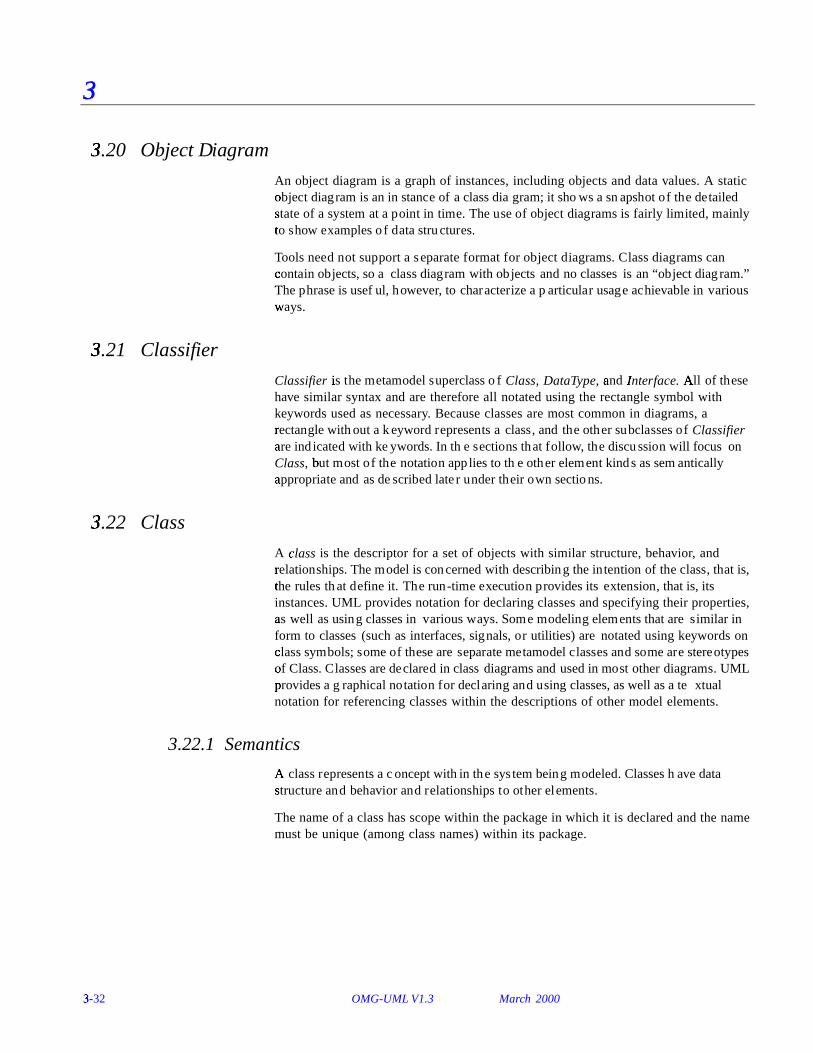
20 Object Diagram
An object diagram is a graph of instances, including objects and data values. A static o� bject diagram is an instance of a class diagram; it shows a snapshot of the detailed state o f a system at a point in time. The use of object diagrams is fairly limited, mainly to
� show examples of data structures.
Tools need not support a separate format for object diagrams. Class diagrams can co� ntain objects, so a class diagram with objects and no classes is an “object diagram.” Th
�e phrase is useful, however, to characterize a particular usage achievable in various
wa ys.
3.�
21 Classifier
Classifier is�
the metamodel superclass of Class, DataType, an� d In�
terface. All o
f these have similar syntax and are therefore all notated using the rectangle symbol with keywords used as necessary. Because classes are most common in diagrams, a r� ectangle without a keyword represents a class, and the other subclasses of Classifier ar� e indicated with keywords. In the sections that follow, the discussion will focus on Class, b
�ut most of the notation applies to the other element kinds as semantically
ap� propriate and as described later under their own sections.
3.�
22 Class
A cla� ss is the descriptor for a set of objects with similar structure, behavior, and r� elationships. The model is concerned with describing the intention of the class, that is, the rules th
�at define it. The run-time execution provides its extension, that is, its
instances. UML provides notation for declaring classes and specifying their properties, as well a� s using classes in various ways. Some modeling elements that are similar in form to classes (such as interfaces, signals, or utilities) are notated using keywords on cla� ss symbols; some of these are separate metamodel classes and some are stereotypes o� f Class. Classes are declared in class diagrams and used in most other diagrams. UML p� rovides a graphical notation for declaring and using classes, as well as a textual notation for referencing classes within the descriptions of other model elements.
3.22.1 Semantics
A cla
ss represents a concept within the system being modeled. Classes have data s tructure and behavior and relationships to other elements.
The name of a class has scope within the package in which it is declared and the name must be unique (among class names) within its package.
OMG-�
UML V1.3 Class March 2000 3-�
33
3
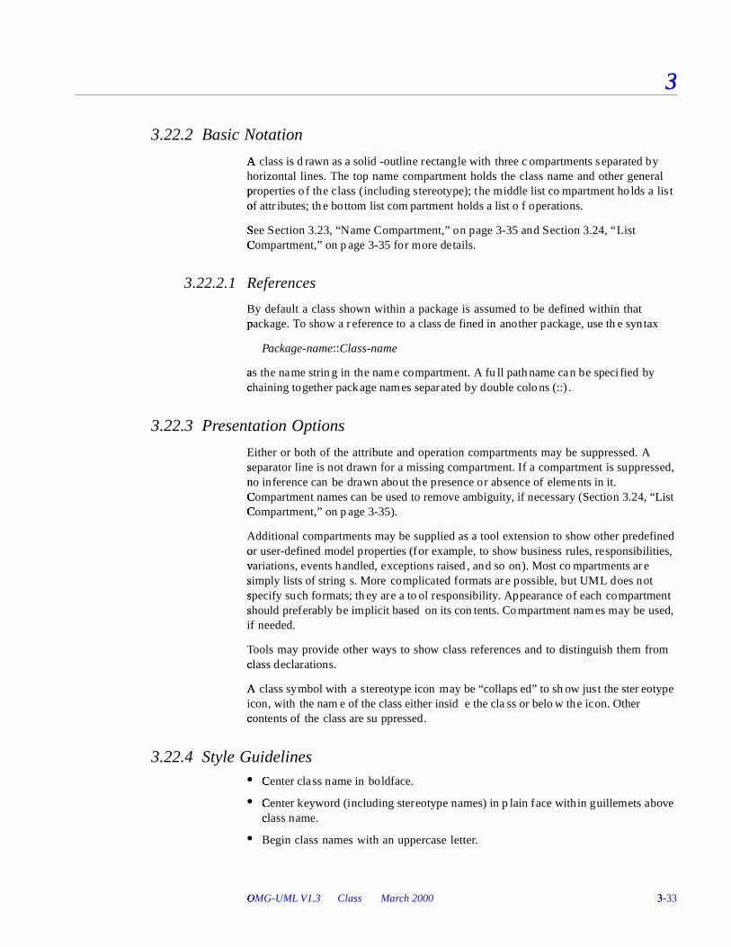
3.22.2 Basic Notation
A cla
ss is drawn as a solid-outline rectangle with three compartments separated by horizontal lines. The top name compartment holds the class name and other general prop� erties of the class (including stereotype); the middle list compartment holds a list of attr� ibutes; the bottom list compartment holds a list of operations.
S�
ee Section 3.23, “N ame Compartment,” on page3-35 and Section 3.24, “ List Co
�mpartment,” on page3-35 for more details.
3.22.2.1 References
By default a class shown within a package is assumed to be defined within that p� ackage. To show a reference to a class defined in another package, use the syntax
Package-name::Class-name
as th� e name string in the name compartment. A fu ll pathname can be specified by chainin� g together package names separated by double colons (::).
3.22.3 Presentation Options
Either or both of the attribute and operation compartments may be suppressed. A separator line is not drawn for a missing compartment. If a compartment is suppressed, n� o inference can be drawn about the presence or absence of elements in it. C
�ompartment names can be used to remove ambiguity, if necessary (Section 3.24, “List
Co�
mpartment,” on page3-35).
Additional compartments may be supplied as a tool extension to show other predefined or u� ser-defined model properties (for example, to show business rules, responsibilities, v� ariations, events handled, exceptions raised, and so on). Most compartments are sim ply lists of strings. More complicated formats are possible, but UML does not sp ecify such formats; they are a tool responsibility . Appearance of each compartment sh ould preferably be implicit based on its contents. Compartment names may be used, if needed.
Tools may provide other ways to show class references and to distinguish them from cla� ss declarations.
A cla
ss symbol with a stereotype icon may be “collapsed” to show just the stereotype icon, with the name of the class either inside the class or below the icon. Other co� ntents of the class are suppressed.
3.22.4 Style Guidelines• C
�enter class name in boldface.
• Cen�
ter keyword (including stereotype names) in plain face within guillemets above cla� ss name.
• Begin class names with an uppercase letter.
3-�
34 OMG-UML V1.3 March 2000
3
• Le�
ft justif y attributes and operations in plain face.
• Begin attribute and operation names with a lowercase letter.
• Sh�
ow the names of abstract classes or the signatures of abstract operations in italics.
As a tool extension, boldface may be used for marking special list elements (for e� xample, to designate candidate keys in a database design). This might encode some d
�esign property modeled as a tagged value, for example.
Sho�
w full attributes and operations when needed and suppress them in other contexts or� references.
3.22.5 Example
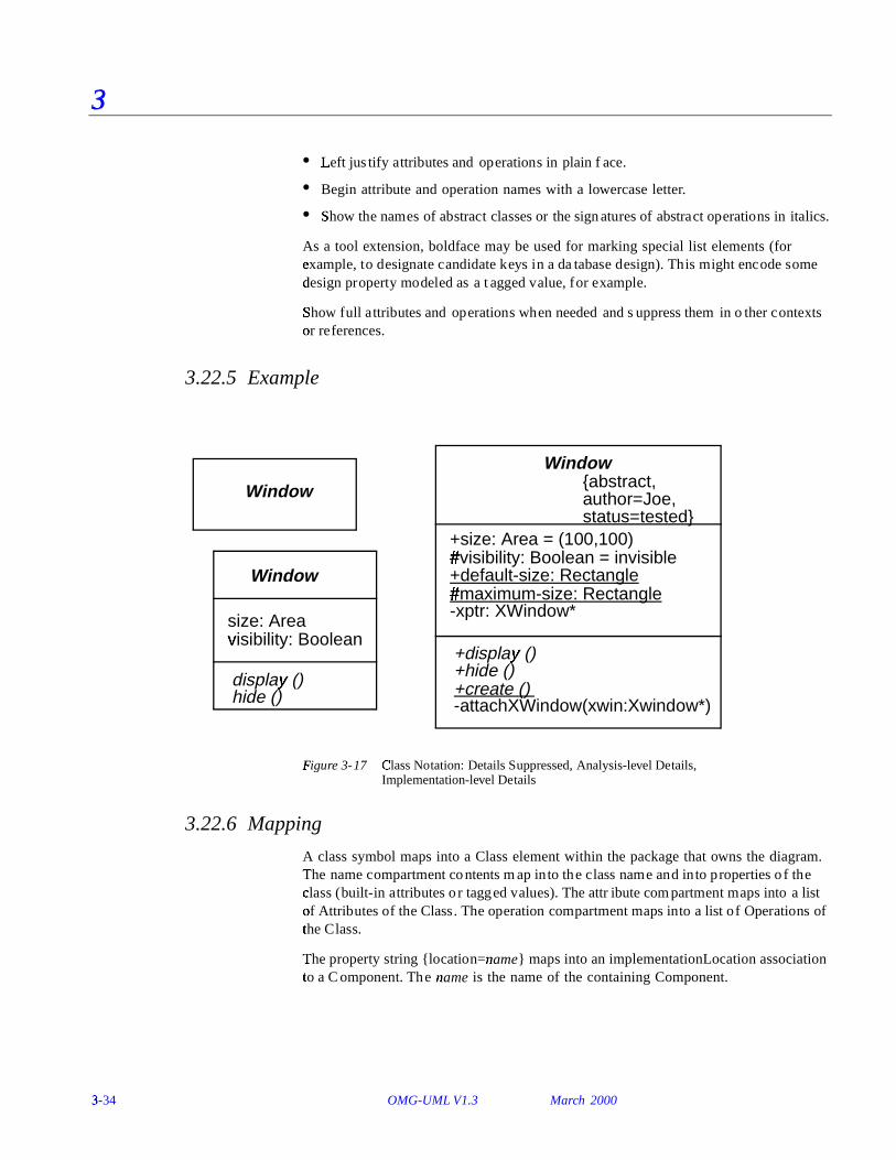
F�
igure 3-17 Cla�
ss Notation: Details Suppressed, Analysis-level Details, Implementation-level Details
3.22.6 Mapping
A class symbol maps into a Class element within the package that owns the diagram. The nam
�e compartment contents map into the class name and into properties of the
cla� ss (built- in attributes or tagged values). The attribute compartment maps into a list of Attrib� utes of the Class. The operation compartment maps into a list of Operations of th
�e Class.
Th�
e property string {lo cation=nam� e} maps into an implementationLocation association to
� a Component. The na� me is the name of the containing Component.
Window
display� ()
size: Areavisi� bility: Boolean
hide ()
Window
Window
+default-size: Rectangle#m
�aximum-size: Rectangle
+create ()
+display� ()
+size: Area = (100,100)#
�visibility: Boolean = invisible
+hide ()
-xptr: XWindow*
-attachXWindow(xwin:Xwindow*)
{abstract,author=Joe,status=tested}

OMG-�
UML V1.3 Name Compartment March 2000 3-�
35
3
3.�
23 Name Compartment
3.23.1 Notation
The name compartment displays the name of the class and other properties in up to three
� sections:
An o
ptional stereotype keyword may be placed above the class name within guillemets, an� d/or a stereotype icon may be placed in the upper right corner of the compartment. The stereotype name must not match a predefined keyword.
The name of the class appears next. If the class is abstract, its name appears in italics. Note th
at any explicit specification of generalization status takes precedence over the
name font.
A list of strings denoting properties (metamodel attributes or tagged values) may be p� laced in braces below the class name. The list may show class-level attributes for wh ich there is no UML n otation and it may also show tagged values. The presence of a k� eyword for a Boolean type without a value implies the value tru! e. For example, a leaf class shows the property “{leaf}”.
The stereotype and property list are optional.
Figure 3-18 Name Compa"
rtment
3.23.2 Mapping
The contents of the name compartment map into the name, stereotype, and various p� roperties of the Class represented by the class symbol.
3.�
24 List Compartment
3.24.1 Notation
A list compartment holds a list of strings, each of which is the encoded representation o� f a feature, such as an attribute or operation. The strings are presented one to a line with o verflow to be handled in a tool-dependent manner. In addition to lists of attr� ibutes or operations, optional lists can show other kinds of predefined or user-def
�ined values, such as responsibilities, rules, or modification histories. UML does not
def�
ine these optional lists. The manipulation of user-defined lists is tool-dependent.
PenTracker
«controller»
{ leaf, author=”Mary Jones”}

3-�
36 OMG-UML V1.3 March 2000
3
The ite�
ms in the list are ordered and the order may be modified by the user. The order of the elem� ents is meaningful information and must be accessible within tools (for e� xample, it may be used by a code generator in generating a list of declarations). The list ele
#ments may be presented in a different order to achieve some other purpose (for
e� xample, they may be sorted in some way). Even if the list is sorted, the items maintain their origin
�al order in the underlying model. The ordering information is merely
su ppressed in the view.
An ellip
sis ( . . . ) as the final element of a list or the final element of a delimited section of a list indicates that additional elements in the model exist that meet the selec tion condition, but that are not shown in that list. Such elements may appear in a dif
�ferent view of the list.
3.24.1.1 Group properties
A p
roperty string may be shown as an element of the list, in which case it applies to all of the su� cceeding list elements until another property string appears as a list element. This is equivalent to attaching the property string to each of the list elements in
�dividually. The property string does not designate a model element. Examples of this
us$ age include indicating a stereotype and specifying visibility . Keyword strings may also b� e used in a similar way to qualify subsequent list elements.
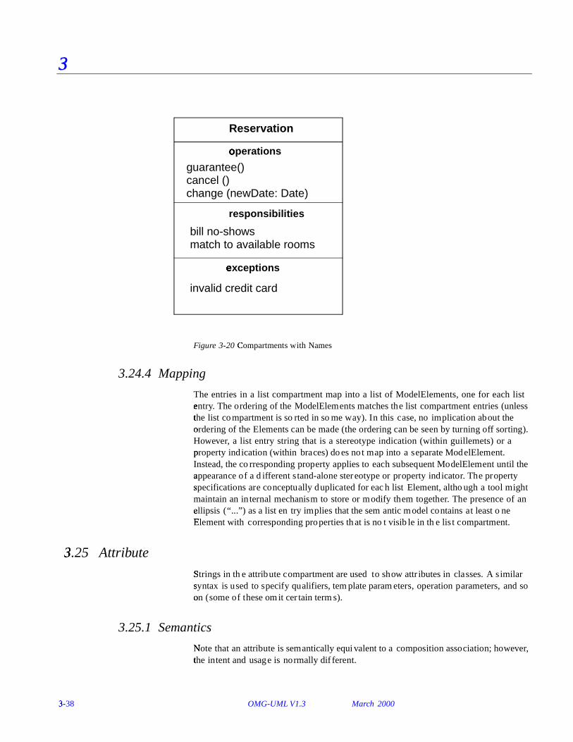
3.24.1.2 Compartment name
A compartment may display a name to indicate which kind of compartment it is. The n� ame is displayed in a distinctive font centered at the top of the compartment. This ca� pability is useful if some compartments are omitted or if additional user-defined co� mpartments are added. For a Class, the predefined compartments are named at% tr ibutes an� d op& erations. An example of a user-defined compartment might be requir ements. The name compartment in a class must always be present; therefore, it do
�es not require or permit a compartment name.
3.24.2 Presentation Options
A too
l may present the list elements in a sorted order, in which case the inherent or� dering of the elements is not visible. A sort is based on some internal property and do
�es not indicate additional model information. Example sort rules include:
• alp� habetical order,
• or� dering by stereotype (such as constructors, destructors, then ordinary methods),
• ordering� by visibility (public, then protected, then private).
The elements in the list may be filtered according to some selection rule. The sp ecif ication of selection rules is a tool responsibility . The absence of items from a filtered list indicates that no elements meet the filter criterion, but no inference can be d
�rawn about the presence or absence of elements that do not meet the criterion.
Ho'
wever, the ellipsis notation is available to show that invisible elements exist. It is a

OMG-�
UML V1.3 List Compartment March 2000 3-�
37
3
too�
l responsibility whether and how to indicate the presence of either local or global filtering, although a stand-alone diagram should have some indication of such filtering if it is to be understandable.
If a compartment is suppressed, no inference can be drawn about the presence or ab� sence of its elements. An empty compartment indicates that no elements meet the selec tion filter (if any).
Note th
at attributes may also be shown by composition (see Figure 3-36 on page3-75).
3.24.3 Example
Figure 3-19 S(
tereotype Keyword Applied to Groups of List Elements
«constructor»Rectangle(p1:Point, p2:Point)«query»area (): Realaspect (): Real
«update»move (delta: Point)scale (ratio: Real). . .
. . .
Rectangle
p1:Pointp2:Point
3-�
38 OMG-UML V1.3 March 2000
3
Figure 3-20 Compart�
ments with Names
3.24.4 Mapping
The entries in a list compartment map into a list of ModelElements, one for each list entry� . The ordering of the ModelElements matches the list compartment entries (unless the list co
�mpartment is sorted in some way). In this case, no implication about the
or� dering of the Elements can be made (the ordering can be seen by turning off sorting). However, a list entry string that is a stereotype indication (within guill emets) or a prop� erty indication (within braces) does not map into a separate ModelElement. Instead, the corresponding property applies to each subsequent ModelElement until the ap� pearance of a different stand-alone stereotype or property indicator. The property sp ecif ications are conceptually duplicated for each list Element, although a tool might maintain an internal mechanism to store or modify them together. The presence of an ellipsis� (“ ...”) as a list entry implies that the semantic model contains at least one Ele
)ment with corresponding properties that is not visible in the list compartment.
3.�
25 Attribute
Strings�
in the attribute compartment are used to show attributes in classes. A similar sy ntax is used to specify qualifiers, template parameters, operation parameters, and so on� (some of these omit certain terms).
3.25.1 Semantics
Note that a
n attribute is semantically equivalent to a composition association; however, the in
�tent and usage is normally dif ferent.
bill no-shows
Reservation
oper* ations
guarantee()cancel ()change (newDate: Date)
responsibilities
match to available rooms
ex+ ceptions
invalid credit card

O�
MG-UML V1.3 Attribute March 2000 3-�
39
3
T�
he type of an attribute is a TypeExpression. It may resolve to a class name or it may b
�e complex, such as ar, ray[String] of P oint.- In any case, the details of the attribute
ty�
pe expressions are not specif ied by UML . They depend on the expression syntax su pported by the particular specif ication or programming language being used.
3.25.2 Notation
An attribute is shown as a text string that can be parsed into the various properties of an attr� ibute model element. The default syntax is:
visibility. na� me [ mu/ ltiplicity ] : t! ype-expression = in0
itial-value { pr1 operty-string }
• W2
here visibility . i�s one of:
+3 public visibility
# 4
protected visibility
- private visibility
The vis�
ibility m arker may be suppressed. The absence of a visibility marker indicates that the visibility is not shown (not that it is undefined or public). A tool sh ould assign visibilities to new attributes even if the visibility is not shown. The vis� ibility m arker is a shorthand for a full visibility. property specif ication string.
V5
isibility m ay also be specif ied by keywords (p1 ublic, protected, private)6. This form
is used particularly when it is used as an inline list element that applies to an entire b
�lock of attributes.
Additional kinds of visibility might be defined for certain programming languages, suc h as C++ imp
0lementation v� isibility (actually all form s of nonpublic visibility are
language-dependent). Such visibility m ust be specif ied by property string or by a to
�ol-specific convention.
• W2
here na� me is an id�
entif ier string that represents the name of the attribute.
• W2
here [ mu/ ltiplicity ] sho7
ws the multiplicity of the attribute (Section 3.42, “Multiplicity ,” on page 3-68). The term may be omitted, in which case the m8 ultiplicity is 1..1 (exactly one).
• W2
here type-! expression is a language-dependent specification of the implementation typ
�e of an attribute.
• W2
here initia0
l-value is a lang�
uage-dependent expression for the initial value of a newly created object. The initial value is optional (the equal sign is also omitted). An explicit constructor for a new object may augment or modify the default initial va� lue.
• W2
here pr1 operty-string indicates property values that apply to the element. The p� roperty string is optional (the braces are omitted if n o properties are specified).
A class-scope attribute is shown by underlin ing the name and type expression string; oth� erwise, the attribute is instance-scope.
cla� ss-scope-attribute
3-�
40 OMG-UML V1.3 March 2000
3
T�
he notation justification is that a class-scope attribute is an instance value in the e� xecuting system, just as an object is an instance value, so both may be designated by un$ derlining. An instance-scope attribute is not underlined; that is the default.
There is no symbol for whether an attribute is changeable (the default is changeable). A no
nchangeable attribute is specified with the property “{fr ozen} .”
I9n the absence of a multip licity in dicator, an attribute holds exactly 1 value.
Multip licity may be indicated by placing a multip licity ind icator in brackets after the attr� ibute name, for example:
co� lors [3]: Colorpo� ints [2..*]: Point
Note th
at a multip licity of 0..1 provides for the possibility o f null v alues: the absence o� f a value, as opposed to a particular value from the range. For example, the following declar
�ation permits a distinction between the nu� ll value and the empty string:
name [0..1]: String
A stereotype keyword in guillemets precedes the entire attribute string, including any v� isibility indicators. A property list in braces follows the rest of the attribute string.
3.25.3 Presentation Options
The type expression may be suppressed (but it has a value in the model).
The initial value may be suppressed, and it may be absent from the model. It is a tool responsibility whether and how to show this distinction.
A tool may show the visibility in dication in a different way, such as by using a special ic
�on or by sorting the elements by group.
A to
ol may show the individual fields of an attribute as columns rather than a co� ntinuous string.
The syntax of the attribute string can be that of a particular programming language, su ch as C++ or Smalltalk . Specific tagged properties may be included in the string.
Particular attributes within a list may be suppressed (see Section 3.24, “List Co
�mpartment,” on page3-35).
3.25.4 Style Guidelines
Attribute names typically begin with a lowercase letter. Attribute names are in plain face.

OMG-�
UML V1.3 Operation March 2000 3-�
41
3
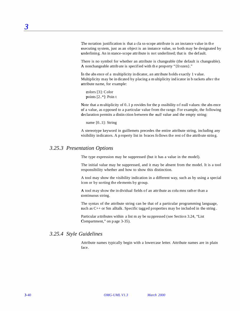
3.25.5 Example
+s: ize: Area = (100,100)#vi
;sibility: Boolean = invisible
+de: fault-size: Rectangle#max
;imum-size: Rectangle
-xptr: XWindowPtr
3.25.6 Mapping
A string
entry within the attribute compartment maps into an Attribute within the Class co� rresponding to the class symbol. The properties of the attribute map in accordance with th e preceding descriptions. If the visibility is absent, then no conclusion can be dra
�wn about the Attribute visibilities unless a filter is in effect (e.g., only public
attr� ibutes shown); likewise, if the type or initial value are omitted. The omission of an un$ derline always indicates an instance-scope attribute. The omission of multiplicity den
�otes a multiplicity of 1.
An
y properties specif ied in braces following the attribute string map into properties on the Attrib
�ute. In addition, any properties specified on a previous stand-alone property
sp ecif ication entry apply to the current Attribute (and to others).
3.�
26 Operation
Entries in the operation compartment are strings that show operations defined on cla� sses and methods supplied by classes.
3.26.1 Semantics
An
operation is a service that an instance of the class may be requested to perform. It has a name and a list of arguments.
3.26.2 Notation
An operation is shown as a text string that can be parsed into the various properties of an� operation model element. The default syntax is:
visibility. na� me ( p1 arameter-list ) : r< eturn-type-expression { pr1 operty-string }
• W2
here visibility . is one of:
+ public visibility
# protected visibility
- private visibility
The visibility marker may be suppressed. The absence of a visibility marker indicates that the visibility is not shown (not that it is undefined or public). The vis� ibility m arker is a shorthand for a full visibility. property specif ication string.

3-�
42 OMG-UML V1.3 March 2000
3
V5
isibility m ay also be specif ied by keywords (p1 ublic, protected, private)6. This form
is used particularly when it is used as an inline list element that applies to an entire b
�lock of operations.
Additional kinds of visibility might be defined for certain programming languages, suc h as C++ imp
0lementation v� isibility (actually all form s of nonpublic visibility are
language-dependent). Such visibility m ust be specif ied by property string or by a to
�ol-specific convention.
• W2
here na� me is an id�
entif ier string.
• W2
here return-type-expression is a language-dependent specif ication of the implementation type or types of the value returned by the operation. The colon and the re
�turn-type are omitted if the operation does not return a value (as for C++
v� oid). A list of e xpressions may be supplied to indicate multip le return values.
• W2
here pa1 rameter-list is a comma-separated list of formal parameters, each specif ied us$ ing the syntax:
k=ind name : t! ype-expression = d
>efault-value
• wh ere kind=
is in?
, out, or� ino?
ut, with th@ e default in?
if absent.
• wh ere na� me is the name of a formal parameter.
• wh ere typ! e-expression is the (language-dependent) specification of an implementation type.
• wh ere d>
efault-value is an optional value expression for the parameter, expressed in an�
d subject to the limitations of the eventual target language.
• W2
here pr1 operty-string indicates property values that apply to the element. The p� roperty string is optional (the braces are omitted if n o properties are specified).
A class-scope operation is shown by underlin ing the name and type expression string. An in
stance-scope operation is the default and is not marked.
A
n operation that does not modify the system state (one that has no side effects) is sp ecif ied by the property “{ query};” oth erwise, the operation may alter the system state, although there is no guarantee that it will do so.
The concurrency semantics of an operation are specified by a property string of the f
Aorm “{c oncurrency = na� me} , where na� me is
� one of the names: sB equential, guarded,
co� ncurrent. As a shorthand, one of the names may be used by itself in a property string to
� indicate the corresponding concurrency value. In the absence of a specif ication, the
co� ncurrency semantics are unspecif ied and must therefore be assumed to be sequential in the worst case.
The top-most appearance of an operation signature declares the operation on the class (
�and inherited by all of its descendents). If this class does not implement the operation
(�i.e., does not supply a method), then the operation may be marked as “{abstract}” or
the o�
peration signature may be italicized to indicate that it is abstract. A subordinate ap� pearance of the operation signature without the {abstract} property indicates that the su bordinate class implements a method on the operation.
The ac�
tual text or algorithm of a method may be indicated in a note attached to the o� peration entry.

OMG-�
UML V1.3 Operation March 2000 3-�
43
3
I9f the objects of a class accept and respond to a given signal, an operation entry with
th�
e keyword «signal» indicates that the class accepts the given signal. The syntax is identical to that of an operation. The response of the object to the reception of the sig nal is shown with a state machine. Among other uses, this notation can show the response of objects of a class to error conditions and exceptions, which should be modeled as signals.
The specif ication of operation behavior is given as a note attached to the operation. Th
�e text of the specif ication should be enclosed in braces if it is a formal specification
in some language (a semantic Constraint); otherwise, it should be plain text if it is just a natural-� language description of the behavior (a Comment).
A stereotype keyword in guillemets precedes the entire operation string, including any v� isibility indicators. A property list in braces follows the entire operation string.
3.26.3 Presentation Options
The argument list and return type may be suppressed (together, not separately).
A tool may show the visibility in dication in a different way, such as by using a special icon or by sorting the elements by group.
The syntax of the operation signature string can be that of a particular programming lang
#uage, such as C++ or Smalltalk . Specific tagged properties may be included in the
str ing.
A method body may be shown in a note attached to the operation entry within the com� partment (Figure 3-21). The line is drawn to the string within the compartment. This ap
�proach is useful mainly for showing small method bodies.
Figure 3-21 Not"
e showing method body
report ()
BurglarAlarm
isTripped: Boolean = false
PoliceStation
1 station
*
{ if isTrippedth
Cen station.alert(self)}
alert ()

3-�
44 OMG-UML V1.3 March 2000
3
3.26.4 Style Guidelines
OperaD
tion names typically begin with a lowercase letter. Operation names are in plain face. An abstract operation may be shown in italics.
3.26.5 Example
Figure 3-22 OperatE
ion List wi th a Variety of Operations
3.26.6 Mapping
A string entry within the operation compartment maps into an Operation or a Method within the Class corresponding to the class symbol. The properties of the operation map in accordance with the preceding descriptions. See the description of “Attribute” on� page3-38 for additional details. Parameters without keywords map into Parameters wi th kind=in, otherwise according to the keyword. Return value names may into Parameters with kind=return.
If the entry has the keyword «signal», then it maps into a Reception on the Class instead.
The topmost appearance of an operation specif ication in a class hierarchy maps into an Opera
Dtion definition in the corresponding Class or Interface. Interfaces do not have
methods. In a Class, each appearance of an operation entry maps into the presence of a Method in the corresponding Class, unless the operation entry contains the {abstract} p� roperty (including use of conventions such as italics for abstract operations). If an ab� stract operation entry appears within a hierarchy in which the same operation has alr� eady been defined in an ancestor, it has no effect but is not an error unless the d
�eclarations are inconsistent.
Note th
at the operation string entry does not specify the body of a method.
3.�
27 Type vs. Implementation Class
3.27.1 Semantics
C�
lasses can be stereotyped as Types or Implementation Classes (although they can be left undifferentiated as well). A Type is used to specify a domain of objects together with o perations applicable to the objects without defining the physical implementation o� f those objects. A Type may not include any methods, but i t may provide behavioral sp ecif ications for its operations. It may also have attributes and associations that are de
�fined solely for the purpose of specif ying the behavior of the type's operations and
d�o not represent any actual implementation of state data.
+create ()
+display� (): Location+hide ()
-attachXWindow(xwin:Xwindow*)
OMG-�
UML V1.3 Type vs. Implementation Class March 2000 3-�
45
3
An
Implementation Class defines the physical data structure (for attributes and asso� ciations) and methods of an object as implemented in traditional languages (e.g., C++,
� Smalltalk). An Implementation Class is said to realize a Type if it provides all of
th�
e operations defined for the Type with the same behavior as specified for the Type's o� perations. An Implementation Class may realize a number of different Types. Note that the
�physical attributes and associations of the Implementation Class do not have to
be th�
e same as those of any Type it realizes and that the Implementation Class may pro� vide methods for its operations in terms of its physical attributes and associations.
An object may have at most one Implementation Class, since this specifies the physical implementation of the object. However, an object may conform to multiple different T
�ypes. If the object has an Implementation Class, then that Implementation Class
sho uld realize the Types to which the object conforms. If dynamic classification is us$ ed, then the Types to which an object conforms may actually change dynamically. A T
�ype may be used in this way to characterize a changeable role that an object may
ad� opt and later abandon.
Although the use of types and implementation classes is different, their internal stru cture is the same and they are both classifiers of objects. Therefore they are m8 odeled as stereotypes of classes. As such, they both fully support the usual genF eralization/specialization and the inheritance of attributes, associations, and op� erations. Note, however, the types may only specialize other types and im
�plementation classes may only specialize other implementation classes. Types and
implementation classes can be related only be realization.
3.27.2 Notation
An undifferentiated class is shown with no stereotype. A type is shown with the ster eotype “«type»” . An implementation class is shown with the stereotype “«implementationClass».” A tool is also free to allow a default setting for an entire diag
�ram, in which case all of the class symbols without explicit stereotype indications
m8 ap into Classes with the default stereotype. This might be useful for a model that is close to� the programming level.
The implementation of a type by a class is modeled as the Realization relationship, sho wn as a dashed line with a solid tr iangular arrowhead (a dashed “generalization ar� row”) . This symbol implies the realizing class provides at least all th e operations of t
�he Type, wi th conforming behavior, but i t does not imply inheritance of structure
(�attributes or associations). The generalization hierarchy of a set of classes frequently
para� llels the generalization hierarchy of a set of types that they realize, but this is not mandatory, as long as each class provides the operations of the types that it realizes.

3-�
46 OMG-UML V1.3 March 2000
3
3.27.3 Example
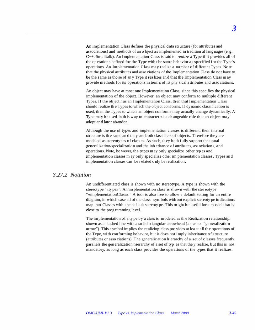
Figure 3-23 Not"
ation for Types and Implementation Classes
3.27.4 Mapping
A class symbol with a stereotype (including “type” and “implementationClass” ) maps into a Class with the corresponding stereotype. A class symbol without a stereotype m8 aps into a Class with the default stereotype for the diagram (if a default has been def
�ined by the modeler or tool); otherwise, it maps into a Class with no stereotype. The
realization arrow between two symbols maps into an Abstraction relationship with the «realize» stereotype between the Classifiers corresponding to the two symbols. Realization is usually used between a class and an interface, but may also be used be
�tween any two classifiers to show conformance of behavior.
3.�
28 Interfaces
3.28.1 Semantics
An interface is a specifier for the externally-visible operations of a class, component, or oth� er classifier (including subsystems) without specification of internal structure. Each interface often specif ies only a limited part of the behavior of an actual class.
Set«type»
addElement(Object)removeElement(Object)t
CestElement(Object):Boolean
* elements
Object«type»
HashTableSet«implementationClass»
addElement(Object)removeElement(Object)te
CstElement(Object):Boolean
1 body
HashTable«implementationClass»
setTableSize(Integer)

OMG-�
UML V1.3 Interfaces March 2000 3-�
47
3
I9nterfaces do not have implementation. They lack attributes, states, or associations;
th�
ey only have operations. (An interface may be the target of a one-way association, b
�ut it may not have an association that it can navigate.) Interfaces may have
gF eneralization relationships. An in terface is formally equivalent to an abstract class with no attributes and no methods and only abstract operations, but Interface is a peer o� f Class within the UML metamodel (both are Classifiers).
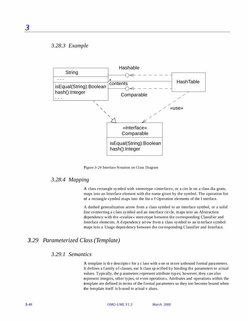
3.28.2 Notation
An in
terface is a Classifier and may be shown using the full rectangle symbol with co� mpartments and the keyword «interface». A l ist of operations supported by the interface is placed in the operation compartment. The attribute compartment may be om� itted because it is always empty.
An
interface may also be displayed as a small circle with the name of the interface p� laced below the symbol. The circle may be attached by a solid line to classifiers that sup port i t. This indicates that the class provides all of the operations in the interface typ
�e (and possibly more). The operations provided are not shown on the circle
notation; use the full rectangle symbol to show the list of operations. A class that uses or r� equires the operations supplied by the interface may be attached to the circle by a dash
�ed arrow pointing to the circle. The dashed arrow implies that the class requires no
more than the operations specified in the interface; the client class is not required to ac� tually use allG of the interface operations.
The Realization relationship from a classifier to an interface that it supports is shown b
�y a dashed line with a solid tr iangular arrowhead (a “dashed generalization symbol”).
This is the same notation used to indicate realization of a type by an implementation cla� ss. In fact, this symbol can be used between any two classifier symbols, with the m8 eaning that the client (the one at the tail of the arrow) supports at least all of the op� erations defined in the supplier (the one at the head of the arrow), but with no necessity to support any of the data structure of the supplier (attributes and asso� ciations).
3-�
48 OMG-UML V1.3 March 2000
3
3.28.3 Example
F�
igure 3-24 IntH
erface Notation on Class Diagram
3.28.4 Mapping
A cla
ss rectangle symbol with stereotype «interface», or a circle on a class diagram, maps into an Interface element with the name given by the symbol. The operation list of a r� ectangle symbol maps into the list of Operation elements of the Interface.
A dashed generalization arrow from a class symbol to an interface symbol, or a solid lin
#e connecting a class symbol and an interface circle, maps into an Abstraction
d�ependency with the «realize» stereotype between the corresponding Classifier and
Interface elements. A dependency arrow from a class symbol to an interface symbol m8 aps into a Usage dependency between the corresponding Classifier and Interface.
3�
.29 Parameterized Class (Template)
3.29.1 Semantics
A tem
plate is the descriptor for a class with one or more unbound formal parameters. It defines a family o f classes, each class specif ied by binding the parameters to actual v� alues. Typically, the parameters represent attribute types; however, they can also r� epresent integers, other types, or even operations. Attributes and operations within the tem
�plate are defined in terms of the formal parameters so they too become bound when
the tem�
plate itself is bound to actual values.
HashTable
Hashable
Comparable
String. . .
isEqual(String):Booleanhash():Integer
contents*
Comparable«interface»
isEqual(String):Booleanhash():Integer
. . .
«use»

OMG-�
UML V1.3 Parameterized Class (Template) March 2000 3-�
49
3
A tem
plate is not a directly usable class because it has unbound parameters. Its p� arameters must be bound to actual values to create a bound form that is a class. Only a c� lass can be a superclass or the target of an association (a one-way association fr
Iom
the tem�
plate to! another class is permissible, however). A template may be a subclass of an o� rdinary class. This implies that all classes formed by binding it are subclasses of t
�he given superclass.
Parameterization can be applied to other ModelElements, such as Collaborations or e� ven entire Packages. The description given here for classes applies to other kinds of modeling elements in the obvious way.
3.29.2 Notation
A small dashed rectangle is superimposed on the upper right-hand corner of the r� ectangle for the class (or to the symbol for another modeling element). The dashed rectangle contains a parameter list of formal parameters for the class and their implementation types. The list must not be empty, although it might be suppressed in th
�e presentation. The name, attributes, and operations of the parameterized class appear
as n� ormal in the class rectangle; however, they may also include occurrences of the formal parameters. Occurrences of the formal parameters can also occur inside of a co� ntext for the class, for example, to show a related class identif ied by one of the pa� rameters.
3.29.3 Presentation Options
The parameter list may be comma-separated or it may be one per line.
Parameters are restricted attributes, shown as strings with the syntax
na� me : ty! pe = defau lt-value
• W2
here na� me is an identif ier for the parameter with scope inside the template.
• W2
here type! is a string designating a TypeExpression for the parameter.
• W2
here defa>
ult-value is a string designating an Expression for a default value that is us$ ed when the corresponding argument is omitted in a Binding. The equal sign and e� xpression may be omitted, in which case there is no default value and the argument must be supplied in a Binding.
If the type name is omitted, the parameter type is assumed to be Classifier. The value s upplied for an argument in a Binding must be the name of a Classifier (including a c� lass or a data type). Other parameter types (such as Integer)
6 must be explicitly
sho wn. The value supplied for an argument in a Binding must be an actual instance v� alue of the given kind.

3-�
50 OMG-UML V1.3 March 2000
3
3.29.4 Example
Figure 3-25 Template Notation with Use of Parameter as a Reference
3.29.5 Mapping
The addition of the template dashed box to a symbol causes the addition of the para� meter names in the list as ModelElements within the Namespace of the ModelElement corresponding to the base symbol (or to the Namespace containing a ModelElement that is not itself a Namespace). Each of the parameter ModelElements has th
Je templateParameter association to the base ModelElement.
3.�
30 Bound Element
3.30.1 Semantics
A
template cannot be used directly in an ordinary relationship such as generalization or assoc� iation, because it has a free parameter that is not meaningful outside of a scope that d
�eclares the parameter. To be used, a template’s parameters must be bo
Kund to
ac� tual values. The actual value for each parameter is an expression defined within the scop e of use. If the referencing scope is itself a template, then the parameters of the referencing template can be used as actual values in binding the referenced template. The para
�meter names in the two templates cannot be assumed to correspond because
the�
y have no scope outside of their respective templates.
FArray
FArray<Point,3>
T,k:IntL
eger
«bind» (Address,24)
Tk..k
AddressList

OMG-�
UML V1.3 Bound Element March 2000 3-�
51
3
3.30.2 Notation
A b
ound element is indicated by a text syntax in the name string of an element, as follows:
Template-name ‘<‘ va. lue-list ‘>’
• W2
here valu. e-list is a comma-delimited non-empty list of value expressions.
• W2
here TMemplate-name is
� identical to the name of a template.
FN
or example, VO
Array<Point,3> de�
signates a class described by the template VaO
rray.
The nu�
mber and type of values must match the number and type of the template para� meters for the template of the given name.
The bound element name may be used anywhere that an element name of the p� arameterized kind could be used. For example, a bound class name could be used with in a class symbol on a class diagram, as an attribute type, or as part of an operation sign ature.
Note that a
bound element is fully specified by its template; therefore, its content may not be extended. Declaration of new attributes or operations for classes is not perm� itted, for example, but a bound class could be subclassed and the subclass e� xtended in the usual way.
The relationship between the bound element and its template alternatively may be s hown by a Dependency relationship with the keyword «bind». The arguments are s hown in parentheses after the keyword. In this case, the bound form may be given a name distinct from the template.
3.30.3 Style Guidelines
The attribute and operation compartments are normally suppressed within a bound c� lass, because they must not be modified in a bound template.
3.30.4 Example
S�
ee Figure 3-25 on page3-50.
3.30.5 Mapping
The use of the bound element syntax for the name of a symbol maps into a Binding d
�ependency between the dependent ModelElement (such as Class) corresponding to
th�
e bound element symbol and the provider ModelElement (again, such as Class) who se name matches the name part of the bound element without the arguments. If the na� me does not match a template element or if the number of arguments in the bound ele� ment does not match the number of parameters in the template, then the model is ill formed. Each argument in the bound element maps into a ModelElement bearing an ar� gument link to the Binding dependency. An explicitly drawn «bind» dependency sy mbol maps to a Binding dependency with arguments as described above.

3-�
52 OMG-UML V1.3 March 2000
3
3.31�
Utility
A utility is a grouping of global variables and procedures in the form of a class declar
�ation. This is not a fundamental construct, but a programming convenience. The
attr� ibutes and operations of the utility become global variables and procedures. A utility$ is modeled as a stereotype of a class.
3.31.1 Semantics
The instance-scope attributes and operations of a utility are interpreted as global attr� ibutes and operations. It is inappropriate for a utility to d eclare class-scope attr� ibutes and operations because the instance-scope members are already interpreted as b� eing at class scope.
3.31.2 Notation
A utility
is shown as the stereotype «utility» of Class. It may have both attributes and o� perations, all of which are treated as global attributes and operations.
3.31.3 Example
Figure 3-26 No"
tation for Util ity
3.31.4 Mapping
This is not a special symbol. It simply maps into a Class element with the «utility » ster eotype.
3.�
32 Metaclass
3.32.1 Semantics
A m
etaclass is a class whose instances are classes.
MathPak«utility»
sin (Angle): Real
sqrt (Real): Realrandom(): Real
cos (Angle): Real

OMG-�
UML V1.3 Enumeration March 2000 3-�
53
3
3.32.2 Notation
A m
etaclass is shown as the stereotype «metaclass» of Class.
3.32.3 Mapping
This is not a special symbol. It simply maps into a Class element with the «metaclass» ster eotype.
3.�
33 Enumeration
3.33.1 Semantics
An Enumeration is a user-defined data type whose instances are a set of user-specified nam� ed enumeration literals. The literals have a relative order but no algebra is defined on� them.
3.33.2 Notation
An Enumeration is shown using the Classifier notation (a rectangle) with the keyword «enumeration». The name of the Enumeration is placed in the upper compartment. An ordered list o� f enumeration literals may be placed, one to a line, in the middle com� partment. Operations defined on the literals may be placed in the lower co� mpartment. The lower and middle compartments may be suppressed.
3.33.3 Mapping
Maps into an Enumeration with the given list of enumeration literals.
3.�
34 Stereotype
3.34.1 Semantics
A Stereotype is a user-defined metaelement whose structure matches an existing UML metaelement.
3.34.2 Notation
A Ster
eotype is shown using the Classifier notation (a rectangle) with the keyword «stereotype». The name of the Stereotype is placed in the upper compartment. C
�onstraints on elements described by the stereotype may be placed in a named
co� mpartment called CP
onstraints. Required tags may be placed in a named co� mpartment called Ta
Qgs.

3-�
54 OMG-UML V1.3 March 2000
3
Th�
e base element may be indicated by a property string of the form {baseElement = name}.
An icon can be defined for the stereotype, but its graphical definition is outside the scop e of UML and must be handled by an editing tool.
3.34.3 Mapping
Maps inR
to a Stereotype with the given constraints and base element.
3.�
35 Powertype
3.35.1 Semantics
A Po
wertype is a user-defined metaelement whose instances are classes in the model.
3.35.2 Notation
A Powertype is shown using the Classifier notation (a rectangle) with the stereotype keyword «powertype». The name of the Powertype is placed in the upper compartment. B
Secause the elements are ordinary classes, attributes and operations on the powertype
a� re usually not defined by the user.
The instances of the powertype may be indicated by placing a dashed line across the pare� nt lines of the classes with the syntax
discriminatorName: powertypeName, @
where the powertype name on the line implicit ly defines a powertype if one is not e� xplicitly d efined.
3.35.3 Mapping
Maps into a Class with the «powertype» stereotype with the given classes as instances.
3.�
36 Class Pathnames
3.36.1 Notation
C�
lass symbols (rectangles) serve to define a class and its properties, such as r� elationships to other classes. A reference to a class in a different package is notated by us$ ing a pathname for the class, in the form:
pa1 ckage-name :: cla� ss-name

OMG-�
UML V1.3 Accessing or Importing a Package March 2000 3-�
55
3
RT
eferences to classes also appear in text expressions, most notably in type spe cif ications for attributes and variables. In these places a reference to a class is indicated by simply including the name of the class itself, including a possible package n� ame, subject to the syntax rules of the expression.
3.36.2 Example
Figure 3-27 PUathnames for Classes in Other Packages
3.36.3 Mapping
A class symbol whose name string is a pathname represents a reference to the Class with the gi ven name inside the package with the given name. The name is assumed to be d
�efined in the target package; otherwise, the model is ill form ed. A Relationship
from a symbol in the current package (i.e., the package containing the diagram and its mapped elements) to a symbol in another package is part of the current package.
3.�
37 Accessing or Importing a Package
3.37.1 Semantics
An element may reference an element contained in a different package. On the package le
#vel, the «access» dependency indicates that the contents of the target package may be
referenced by the client package or packages recursively embedded within it. The tar
�get references must have visibility sufficient for the referents: public visibility for an
un$ related package, public or protected visibility for a descendent of the target package, o� r any visibil ity for a package nested inside the target package (an access dependency is not required for the latter case). A package nested inside the package making the ac� cess gets the same access.
Banking::CheckingAccount
Deposit
time: DC
ateTime::Timeamount: Currency::Cash

3-�
56 OMG-UML V1.3 March 2000
3
No
te that an access dependency does not modify the namespace of the client or in any oth� er way automatically create references; it merely grants permission to establish references. Note also that a tool could automatically create access dependencies for u$ sers if desired when references are created.
An
import dependency grants access and also loads the names with appropriate v� isibility in the target namespace into the accessing package (i.e., a pathname is not necessary to reference them). Such names are not automatically reexported; however, a nam� e must be explicitly reexported (and may be given a new name and visibility at the sam e time).
3.37.2 Notation
The access dependency is displayed as a dependency arrow from the referencing (
�client) package to the target (supplier) package containing the target of the references.
The arrow has the stereotype keyword «access». This dependency indicates that ele� ments within the client package may legally reference elements within the supplier. The r
�eferences must also satisfy visibility constraints specif ied by the supplier. Note
th�
at the dependency does not automatically create any references. It merely grants perm� ission for them to be established.
The import dependency has the same notation as the access dependency except it has t
�he stereotype keyword «import».

OMG-�
UML V1.3 Object March 2000 3-�
57
3
3.37.3 Example
F�
igure 3-28 Access Dependency Among Packages
3.37.4 Mapping
This is n�
ot a special symbol. It maps into a Permission dependency with the stereotype «access» or «import» between the two packages.
3.�
38 Object
3.38.1 Semantics
An object represents a particular instance of a class. It has identity and attribute values. A similar notation also represents a role within a collaboration because roles have ins
�tance-like characteristics.
3.38.2 Notation
The object notation is derived from the class notation by underlining instance-level ele� ments, as explained in the general comments in Section3.12, “Type-Instance C
�orrespondence,” on page3-14.
An
object shown as a rectangle with two compartments.
Banking::CheckingAccount
CheckingAccount
Banking
«access»
Customers
3-�
58 OMG-UML V1.3 March 2000
3
The to�
p compartment shows the name of the object and its class, all underlined, using th
�e syntax:
obV jectname : cla� ssname
The classname can include a full pathname of enclosing package, if necessary. The p� ackage names precede the classname and are separated by double colons. For ex� ample:
display_window: WindowingSystem::GraphicWindows::Window
A stereotype for the class may be shown textually (in guillemets above the name strin g) or as an icon in the upper right corner. The stereotype for an object must match th
�e stereotype for its class.
To show multiple classes that the object is an instance of, use a comma-separated list of cla� ssnames. These classnames must be legal for multip le classification (i.e., only on� e implementation class permitted, but multiple types permitted).
T�o show the presence of an object in a particular state of a class, use the syntax:
obV jectname : cla� ssname ‘[ ‘ staB tename-list ‘] ’
The list m�
ust be a comma-separated list of names of states that can legally occur co� ncurrently.
The second compartment shows the attributes for the object and their values as a list. Each value line has the syntax:
attrG ibutename : type! = va. lue
The type is redundant with the attribute declaration in the class and may be omitted.
The value is specified as a literal value. UML does not specify the syntax for literal v� alue expressions; however, it is expected that a tool will sp ecify such a syntax using so me programming language.
The flow relationship between two values of the same object over time can be shown b
�y connecting two object symbols by a dashed arrow with the keyword «become». If
th�
e flow arrow is on a collaboration diagram, the label may also include a sequence number to show when the value changes. Similarly, the keyword «copy» can be used to sho w the creation of one object from another object value.
3.38.3 Presentation Options
The nam�
e of the object may be omitted. In this case, the colon should be kept with the cla� ss name. This represents an anonymous object of the given class given identity by its relationships.
The class of the object may be suppressed (together with the colon).
The attribute value compartment as a whole may be suppressed.
Attributes whose values are not of interest may be suppressed.

OMG-�
UML V1.3 Object March 2000 3-�
59
3
Attr
ibutes whose values change during a computation may show their values as a list of v� alues held over time. In an interactive tool, they might even change dynamically. An alte� rnate notation is to show the same object more than once with a «becomes» r� elationship between them.
3.38.4 Style Guidelines
ObD
jects may be shown on class diagrams. The elements on collaboration diagrams are not objects, because they describe many possible objects. They are instead roles that m8 ay be held by object. Objects in class diagrams serve mainly to show examples of da
�ta structures.
3.38.5 Variations
For a language such as SelW
f in which operations can be attached to individual objects at r� un time, a third compartment containing operations would be appropriate as a language-specific extension.
3.38.6 Example
F�
igure 3-29 ObjE
ects
3.38.7 Mapping
I9n an object diagram, or within an ordinary class diagram, an object symbol maps into
an� Object of the Class (or Classes) given by the cla� ssname part of the name string. The attr� ibute list in the symbol maps into a set of AttributeLinks attached to the Object, with values given by the value expressions in the attribute list in the symbol. If a list of states in brackets follows the class name, then this maps into a ClassifierInState with th
�e named Class as its type and the named States as the states.
triaC
ngle: Polygon
cX enter = (0,0)veY rtices = ((0,0),(4,0),(4,3))borderColor = blackfi
ZllColor = white
triaC
ngle: Polygon
trC
iangle
:Polygon
scheduler

3-�
60 OMG-UML V1.3 March 2000
3
3.�
39 Composite Object
3.39.1 Semantics
A composite object represents a high-level object made of tightly-bound parts. This is an in� stance of a composite class, which implies the composition aggregation between the class and
� its parts. A composite object is similar to (but simpler and more restricted
than�
) a collaboration; however, it is defined completely by composition in a static mo8 del. See Section 3.46, “ Composition,” on page3-73.
3.39.2 Notation
A composite object is shown as an object symbol. The name string of the composite o� bject is placed in a compartment near the top of the rectangle (as with any object). Th
�e lower compartment holds the parts of the composite object instead of a list of
attr� ibute values. (However, even a list of attribute values may be regarded as the parts of a com� posite object, so there is not a great difference.) It is possible for some of the parts to b� e composite objects with further nesting.
3.39.3 Example
Figure 3-30 Composi�
te Objects
horizontalBar:ScrollBar
verticalBar:ScrollBar
awindow : Window
surface:Pane
title:C
TitleBar
moves
moves

OMG-�
UML V1.3 Binary Association March 2000 3-�
61
3
3.39.4 Mapping
A com
posite object symbol maps into an Object of the given Class with composition links to each of the Objects and Links corresponding to the class box symbols and to asso� ciation path symbols directly contained within the boundary of the composite ob� ject symbol (and not contained within another deeper boundary).
3.39.5 Association
Binary associations are shown as lines connecting two classifier symbols. The lines may have a variety of adornments to show their properties. Ternary and higher-order assoc� iations are shown as diamonds connected to class symbols by lines.
3.�
40 Binary Association
3.40.1 Semantics
A bin
ary association is an association among exactly two classifiers (including the po� ssibility o f an association from a classifier to itself).
3.40.2 Notation
A binary association is drawn as a solid path connecting two classifier symbols (both en� ds may be connected to the same classifier, but the two ends are distinct). The path may consist of one or more connected segments. The individual segments have no sem antic signif icance, but may be graphically meaningful to a tool in dragging or r� esizing an association symbol. A connected sequence of segments is called a pa1 th.
I9n a binary association, both ends may attach to the same classifier. The links of such
an� association may connect two different instances from the same classifier or one instance to itself. The latter case may be forbidden by a constraint if necessary.
The end of an association where it connects to a classifier is called an aG ssociation end. Most o
Rf the interesting information about an association is attached to its ends.
Th�
e path may also have graphical adornments attached to the main part of the path itself. These adornments indicate properties of the entire association. They may be dragg
�ed along a segment or across segments, but must remain attached to the path. It is
a too� l responsibility to determine how close association adornments may approach an e� nd so that confusion does not occur. The following kinds of adornments may be atta� ched to a path.
3.40.2.1 association name
Designates the (optional) name of the association.

3-�
62 OMG-UML V1.3 March 2000
3
I9t is shown as a name string near the path (but not near enough to an end to be
con� fused with a rolename). The name string may have an optional small b lack solid tr
�iangle in it. The point of the triangle indicates the direction in which to read the
nam� e. The name-direction arrow has no semantics signif icance, it is purely descriptive. The classifiers in the association are ordered as indicated by the name-direction arrow.
No[
te – Th�
ere is no need for a na� me direction p� roperty on the association model; the o� rdering of the classifiers within the association is
0the n�
ame direction. This convention w orks even with n-ary associations.
A stereotype keyword within guillemets may be placed above or in front of the asso� ciation name. A property string may be placed after or below the association name.
3.40.2.2 association class symbol
Designates an association that has class-like properties, such as attributes, operations, and� other associations. This is present if, and only if, the association is an association cla� ss. It is shown as a class symbol attached to the association path by a dashed line.
The association path and the association class symbol represent the same underlying model element, which has a single name. The name may be placed on the path, in the c� lass symbol, or on both (but they must be the same name).
Logically�
, the association class and the association are the same semantic entity; however, they are graphically distinct. The association class symbol can be dragged a� way from the line, but the dashed l ine must remain attached to both the path and the cla� ss symbol.
3.40.3 Presentation Options
Wh2
en two paths cross, the crossing may optionally be shown with a small semicircular jog
\ to indicate that the paths do not intersect (as in electrical circuit diagrams).
3.40.4 Style Guidelines
Li�
nes may be drawn using various styles, including orthogonal segments, oblique se gments, and curved segments. The choice of a particular set of line styles is a user ch� oice.
3.40.5 Options
3.40.5.1 Xor-association
An xor
-constraint indicates a situation in which only one of several potential asso� ciations may be instantiated at one time for any single instance. This is shown as a dash
�ed line connecting two or more associations, all of which must have a classifier in

OMG-�
UML V1.3 Binary Association March 2000 3-�
63
3
com� mon, with the constraint string “{xo r}” labelin g the dashed li ne. Any instance of th
�e classifier may only participate in one of the associations at one time. Each
rolename must be different. (This is simply a predefined use of the constraint notation.)
3.40.6 Example
Figure 3-31 Association Notation
3.40.7 Mapping
An association path connecting two class symbols maps to an Association between the co� rresponding Classifiers. If there is an arrow on the association name, then the Class corr� esponding to the tail of the arrow is the first class and the Classifier corresponding to
� the head of the arrow is the second Classifier in the ordering of ends of the
Asso
ciation; otherwise, the ordering of ends in the association is undetermined. The ado� rnments on the path map into properties of the Association as described above. The Association is owned by the package containing the diagram.
Person
Manag] es
JobCompany
boss
worker
employeeemployer1..∗
∗
∗
0..1
Job
Account
Person
Corporation
{Xor}
salary

3-�
64 OMG-UML V1.3 March 2000
3
3.�
41 Association End
3.41.1 Semantics
An association end is simply an end of an association where it connects to a classifier. I
9t is part of the association, not part of the classifier. Each association has two or more
end� s. Most of the interesting details about an association are attached to its ends. An assoc� iation end is not a separable element, it is just a mechanical part of an association.
3.41.2 Notation
Th�
e path may have graphical adornments at each end where the path connects to the cla� ssifier symbol. These adornments indicate properties of the association related to the cla� ssifier. The adornments are part of the association symbol, not part of the classifier sym bol. The end adornments are either attached to the end of the line, or near the end o� f the line, and must drag with it. The following kinds of adornments may be attached to
� an association end.
3.41.2.1 multiplicity
Specif�
ied by a text syntax, multip licity m ay be suppressed on a particular association or f� or an entire diagram. In an incomplete model the multiplicity may be unspecif ied in the m
�odel itself. I n this case, it must be suppressed in the notation. See Section3.42,
“Multiplicity,” on page 3-68.
3.41.2.2 ordering
If the multiplicity is greater than one, then the set of related elements can be ordered or u$ nordered. If no indication is given, then i t is unordered (the elements form a set). V
5arious kinds of ordering can be specif ied as a constraint on the association end. The
declar�
ation does not specify how the ordering is established or maintained. Operations that in
�sert new elements must make provision for specifying their position either
implicitly (such as at the end) or explicitly . Possible values include:
• un$ ordered - the elements form an unordered set. This is the default and need not be sh own explicitly .
• ordered - the ele� ments of the set have an ordering, but duplicates are still pr� ohibited. This generic specification includes all k inds of ordering. This may be spe cif ied by the keyword syntax “{or dered}”.
An o
rdered relationship may be implemented in various ways; however, this is normally specified as a language-specified code generation property to select a partic� ular implementation. An implementation extension might substitute the data stru cture to hold the elements for the generic specification “ordered.”
At im
plementation level, sorting may also be specified. It does not add new semantic information, but it expresses a design decision:
OMG-�
UML V1.3 Association End March 2000 3-�
65
3
• sor ted - the elements are sorted based on their internal values. The actual sorting rule is best specified as a separate constraint.
3.41.2.3 qualifier
A qualifier is optional, but not suppressible. See Section 3.43, “Qualif ier,” on p� age3-69.
3.41.2.4 navigability
An arrow may be attached to the end of the path to indicate that navigation is sup ported toward the classifier attached to the arrow. Arrows may be attached to zero, on� e, or two ends of the path. To be totally explicit, arrows may be shown whenever navigation is supported in a given direction. In practice, it is often convenient to sup press some of the arrows and just show exceptional situations. See Section 3.22.3, “Presentation Options,” on page3-33 for details.
3.41.2.5 aggregation indicator
A hollow diamond is attached to the end of the path to indicate aggregation. The diam
�ond may not be attached to both ends of a line, but it need not be present at all.
Th�
e diamond is attached to the class that is the aggregate. The aggregation is optional, b
�ut not suppressible.
If the diamond is filled, then it signif ies the strong form of aggregation known as comp� osition. See Sec
�tion 3.46, “Composition,” on page3-73.
3.41.2.6 rolename
A name string near the end of the path. It indicates the role played by the class atta� ched to the end of the path near the rolename. The rolename is optional, but not su ppressible.
3.41.2.7 interface specifier
The name of a Classifier with the syntax:
‘: ’ c� lassifiername , . . .
It indicates the behavior expected of an associated object by the related instance. In o� ther words, the interface specifier specifies the behavior required to enable the asso� ciation. In this case, the actual classifier usually provides more functionality than required for the particular association (since it may have other responsibilities).
The use of a rolename and interface specifier are equivalent to creating a small collabo� ration that includes just an association and two roles, whose structure is defined b
�y the rolename and attached classifier on the original association. Therefore, the

3-�
66 OMG-UML V1.3 March 2000
3
o� riginal association and classifiers are a use of the collaboration. The original classifier must be compatible with the interface specifier (which can be an interface or a type, am� ong other kinds of classifiers).
If an interface specif ier is omitted, then the association may be used to obtain full ac� cess to the associated class.
3.41.2.8 changeability
I9f the links are changeable (can be added, deleted, and moved), then no indicator is
needed. The property { frozen} indicates that no links may be added, deleted, or moved from an object (toward the end with the adornment) after the object is created and initialized. The prop
�erty { addOnly} ind icates that additi onal links may be added
(�presumably, the multip licit y is variable); however, link s may not be modified or
deleted.�
3.41.2.9 visibility
Specif�
ied by a visibility ind icator (‘+’ , ‘ #’ , ‘- ’ or explicit property name such as {public}) in front of the rolename. Specif ies the visibility of the association traversing in the direction toward the given rolename. See “Attribute” on page3-38 for details of vis� ibility specification.
OthD
er properties can be specified for association ends, but there is no graphical syntax f
Aor them. To specify such properties, use the constraint syntax near the end of the
assoc� iation path (a text string in braces). Examples of other properties include mutability.
3.41.3 Presentation Options
I9f there are two or more aggregations to the same aggregate, they may be drawn as a
tr�
ee by merging the aggregation end into a single segment. This requires that all o f the ado� rnments on the aggregation ends be consistent. This is purely a presentation option, there
� are no additional semantics to i t.
V5
arious options are possible for showing the navigation arrows on a diagram. These ca� n vary from time to time by user request or from diagram to diagram.
• Presentation option 1: Show all arrows. The absence of an arrow indicates na� vigation is not supported.
• Presentation option 2: Suppress all arrows. No inference can be drawn about navigation. This is similar to any situation in which information is suppressed from a v� iew.
• Presentation option 3: Suppress arrows for associations with navigability in both direc
�tions, show arrows only for associations with one-way navigability. In this
ca� se, the two-way navigability cannot be distinguished from no-way navigation; however, the latter case is normally rare or nonexistent in practice. This is yet ano� ther example of a situation in which some information is suppressed from a vie� w.

OMG-�
UML V1.3 Association End March 2000 3-�
67
3
3.41.4 Style Guidelines
I9f there are multiple adornments on a single association end, they are presented in the
following order, reading from the end of the path attached to the classifier toward the b
�ulk of the path:
• qu^ alifier
• ag� gregation symbol
• navigation arrow
Rolenames and multiplicity should be placed near the end of the path so that they are n� ot confused with a different association. They may be placed on either side of the line. It is tempting to specify that they will always be placed on a given side of the line (
�clockwise or counterclockwise), but this is sometimes overridden by the need for
cla� rity in a crowded layout. A rolename and a multip licity may be placed on opposite side s of the same association end, or they may be placed together (for example, “* em� ployee”).
3.41.5 Example
F�
igure 3-32 V_
arious Adornments on Association Roles
3.41.6 Mapping
Th�
e adornments on the end of an association path map into properties of the corr� esponding role of the Association. In general, implications cannot be drawn from th
�e absence of an adornment (it may simply be suppressed) but see the preceding
d�escriptions for details. The interface specif ier maps into the “specification” rolename
in the AssociationEnd-Classif ier association.
Polygon PointContains
{ordered}
3..∗1
GraphicsBundle
colortext
Cure
density
1
1
-bundle
+points

3-�
68 OMG-UML V1.3 March 2000
3
3.�
42 Multiplicity
3.42.1 Semantics
A multiplicity item specif ies the range of allowable cardinalities that a set may assume. Multip
Rlicity specif ications may be given for roles within associations, parts within
com� posites, repetitions, and other purposes. Essentially a multiplicity specification is a su bset of the open set of non-negative integers.
3.42.2 Notation
A m
ultiplicity specification is shown as a text string comprising a comma-separated sequ ence of integer intervals, where an interval represents a (possibly infinite) range of integers, in the format:
l`ower-bound .. upa per-bound
wh ere l`ower-bound and� upa per-bound are literal integer values, specifying the closed
(�inclusive) range of integers from the lower bound to the upper bound. In addition, the
sta r character (* ) may be used for the upper bound, denoting an unlimited upper bo
�und. In a parameterized context (such as a template), the bounds could be
e� xpressions but they must evaluate to literal integer values for any actual use. Unbound e� xpressions that do not evaluate to literal in teger values are not permitted.
If a single integer value is specif ied, then the integer range contains the single integer va� lue.
If the multiplicity specif ication comprises a single star (*), then it denotes the un$ limited nonnegative integer range, that is, it is equivalent to 0..* (zero or more).
A m
ultiplicity of 0..0 is meaningless as it would indicate that no instances can occur.
Expressio)
ns in some specif ication language can be used for multip licities, but they must resolve to fixed integer ranges within the model (i.e., no dynamic evaluation of e� xpressions, essentially the same rule on literal values as most programming la
#nguages).
3.42.3 Style Guidelines
Preferably, intervals should be monotonically increasing. For example, “1..3,7,10” is p� referable to “7 ,10,1..3”.
Two contiguous intervals should be combined into a single interval. For example, “0..1” is preferable to “0,1” .
3.42.4 Example
0b..1
1

OMG-�
UML V1.3 Qualifier March 2000 3-�
69
3
0b..*
*
1..*
1..6
1..3,7..10,15,19..*
3.42.5 Mapping
A multiplicity string maps into a Multiplicity value with one or more MultiplicityRanges. Duplications or other nonstandard presentation of the string itself ha
Jve no effect on the mapping. Note that Multiplicity is a value and not an object. It
ca� nnot stand on its own, but is the value of some element property.
3.�
43 Qualifier
3.43.1 Semantics
A qualifier is an attribute or list of attributes whose values serve to partition the set of instances associated with an instance across an association. The qualifiers are attributes o� f the association.
3.43.2 Notation
A qualifier is shown as a small rectangle attached to the end of an association path between
�the final path segment and the symbol of the classifier that it connects to. The
qu^ alifier rectangle is part of the association path, not part of the classifier. The qualif ier rectangle drags with the path segments. The qualifier is attached to the source end of th
�e association. An instance of the source classifier, together with a value of the
qu^ alifier, uniquely select a partition in the set of target classifier instances on the other end� of the association (i.e., every target falls into exactly one partition).
The multiplicity attached to the target end denotes the possible cardinalities of the set o� f target instances selected by the pairing of a source instance and a qualif ier value. Co
�mmon values include:
• “0..1” (a unique value may be selected, but every possible qualifier value does not necessarily select a value).
• “1” (every possible qualif ier value selects a unique target instance; therefore, the do
�main of qualif ier values must be finite).
• “*” ( the qualifier value is an index that partitions the target instances into subsets).
The qualifier attributes are drawn within the qualifier box. There may be one or more attr� ibutes shown one to a line. Qualifier attributes have the same notation as classifier a� ttributes, except that initial value expressions are not meaningful.

3-�
70 OMG-UML V1.3 March 2000
3
It is9
permissible (although somewhat rare), to have a qualif ier on each end of a single asso� ciation.
3.43.3 Presentation Options
A qualifier may not be suppressed (it provides essential detail whose omission would m8 odify the inherent character of the relationship).
A to
ol may use a lighter line for qualif ier rectangles than for class rectangles to d
�istinguish them clearly.
3.43.4 Style Guidelines
The qualifier rectangle should be smaller than the attached class rectangle, although this
� is not always practical.
3.43.5 Example
F�
igure 3-33 Qualc
ified Associations
3.43.6 Mapping
Th�
e presence of a qualif ier box on an end of an association path maps into a list of qu^ alifier attributes on the corresponding Association Role. Each attribute entry string inside the qualif ier box maps into an Attr ibute.
3.�
44 Association Class
3.44.1 Semantics
An association class is an association that also has class properties (or a class that has asso� ciation properties). Even though it is drawn as an association and a class, it is really just a single model element.
Square
Chessboard
rank:Rankfile:File
Person
Bank
account #
∗0..1 1
1

OMG-�
UML V1.3 Association Class March 2000 3-�
71
3
3.44.2 Notation
An
association class is shown as a class symbol (rectangle) attached by a dashed line to an� association path. The name in the class symbol and the name string attached to the asso� ciation path are redundant and they should be the same. The association path may h
Jave the usual adornments on either end. The class symbol may have the usual
co� ntents. There are no adornments on the dashed line.
3.44.3 Presentation Options
The class symbol may be suppressed. It provides subordinate detail whose omission do
�es not change the overall relationship. The association path may not be suppressed.
3.44.4 Style Guidelines
The attachment point should not be near enough to either end of the path that it app� ears to be attached to the end of the path, or to any of the association end a� dornments.
No
te that the association path and the association class are a single model element and have a single name. The name can be shown on the path, the class symbol, or both. If an asso� ciation class has only attributes, but no operations or other associations, then the n
�ame may be displayed on the association path and omitted from the association
cla� ss symbol to emphasize its “association nature.” I f it has operations and other asso� ciations, then the name may be omitted from the path and placed in the class r� ectangle to emphasize its “class nature.” I n neither case are the actual semantics d
�ifferent.
3.44.5 Example
F�
igure 3-34 Association Class
Person
Manag] es
Company
boss
wod rker
employeeemployer1..∗
∗
∗
0..1
Jobsalary

3-�
72 OMG-UML V1.3 March 2000
3
3.44.6 Mapping
An
association path connecting two class boxes connected by a dashed line to another cla� ss box maps into a single AssociationClass element. The name of the AssociationClass element is taken from the association path, the attached class box, or bo
�th (they must be consistent if both are present). The Association properties map from
the asso�
ciation path, as specif ied previously. The Class properties map from the class bo
�x, as specif ied previously. Any constraints or properties placed on either the
asso� ciation path or attached class box apply to the AssociationClass itself; they must not conflict.
3.�
45 N-ary Association
3.45.1 Semantics
An n-ary association is an association among three or more classifiers (a single cla� ssifier may appear more than once). Each instance of the association is an n-tuple of v� alues from the respective classifier. A binary association is a special case with its own notation.
Multiplicity for n-ary associations may be specif ied, but is less obvious than binary multiplicity . The multiplicity on a role represents the potential number of instance tup
�les in the association when the other N-1 values are fixed.
A
n n-ary association may not contain the aggregation marker on any role.
3.45.2 Notation
An n-ary association is shown as a large diamond (that is, large compared to a ter
�minator on a path) with a path from the diamond to each participant class. The name
o� f the association (if any) is shown near the diamond. Role adornments may appear on ea� ch path as with a binary association. Multiplicity m ay be indicated; however, qu^ alifiers and aggregation are not permitted.
An association class symbol may be attached to the diamond by a dashed line. This in
�dicates an n-ary association that has attributes, operations, and/or associations.
3.45.3 Style Guidelines
Usuallye
the lines are drawn from the points on the diamond or the midpoint of a side.
3.45.4 Example
This example shows the record of a team in each season with a particular goalkeeper. I
9t is assumed that the goalkeeper might be traded during the season and can appear
with dif ferent teams

OMG-�
UML V1.3 Composition March 2000 3-�
73
3
.
Figure 3-35 Ternary association that is also an association class
3.45.5 Mapping
A diamond attached to some number of class symbols by solid lines maps into an N-ar� y Association whose AssociationEnds are attached to the corresponding Classes. The ordering� of the Classifiers in the Association is indeterminate from the diagram. If a cla� ss box is attached to the diamond by a dashed line, then the corresponding Classifier su pplies the classifier properties for an N-ary AssociationClass.
3.�
46 Composition
3.46.1 Semantics
Co�
mposition is a form of aggregation with strong ownership and coincident lif etime of part with th� e whole. The multiplicity o f the aggregate end may not exceed one (it is u$ nshared). See Section 3.41, “Association End,” on page3-64 for further details.
The parts of a composition may include classes and associations (they may be formed into
� AssociationClasses if necessary). The meaning of an association in a composition
is that any tuple of objects connected by a single link must all belong to the saB me co� ntainer object.
PlayerTeam
Year
Record
goals forgoals againstwind slosses
goalkeeper
∗
∗
∗
season
teC
am
tieC
s

3-�
74 OMG-UML V1.3 March 2000
3
3.46.2 Notation
Co�
mposition may be shown by a solid filled diamond as an association end adornment. Alternately, UML provides a graphically -nested form that is more convenient for sh owing composition in many cases.
Instead of using binary association paths using the composition aggregation ado� rnment, composition may be shown by graphical nesting of the symbols of the ele� ments for the parts within the symbol of the element for the whole. A nested class-like element may have a multiplicity with in its composite element. The multiplicity is sh own in the upper right corner of the symbol for the part. If the multip lici ty mark is om� itted, then the default multip licity is many. This represents its multiplicity as a part within the composite classifier. A nested element may have a rolename within the com� position; the name is shown in front of its type in the syntax:
ro< lename ‘: ’ cla� ssname
This repre�
sents its rolename within its composition association to the composite.
Alter
nately, composition is shown by a solid-f illed diamond adornment on the end of an asso� ciation path attached to the element for the whole. The multiplicity may be sh own in the normal way.
Note th
at attributes are, in effect, composition relationships between a classifier and th
�e classifiers of its attributes.
An
association drawn entirely within a border of the composite is considered to be part of the com� position. Any instances on a single link of it m ust be from the same co� mposite. An association drawn such that its path breaks the border of the composite is n
�ot considered to be part of the composition. Any instances on a single link of it
may be from the same or different composites.
Note th
at the notation for composition resembles the notation for collaboration. A com� position may be thought of as a collaboration in which all of the participants are pa� rts of a single composite object.
Note th
at nested notation is not the correct way to show a class declared within another cla� ss. Such a declared class is not a structural part of the enclosing class but merely has sco pe within the namespace of the enclosing class, which acts like a package toward th
�e inner class. Such a namescope containment may be shown by placing a package
sym bol in the upper right corner of the class symbol. A tool can allow a user to click o� n the package symbol to open the set of elements declared within it.
3.46.3 Design Guidelines
No
te that a class symbol is a composition of it s attributes and operations. The class sy mbol may be thought of as an example of the composition nesting notation (with so me special layout properties). However, attribute notation subordinates the attributes stron gly within the class; therefore, it should be used when the structure and identity of the attr
�ibute objects themselves is unimportant outside the class.

OMG-�
UML V1.3 Composition March 2000 3-�
75
3
3.46.4 Example
Figure 3-36 Different Ways to Show Composition
Window
scrollbar [2]: Slidert
fitle: Headerbody: Panel
Windowg
scrollbar tiCtle body
scrollbar:Slider
Header Panel
2 1 1
Wg
indow
Slider
2
tiCtle:Header
1
body:Panel1
111

3-�
76 OMG-UML V1.3 March 2000
3
3.46.5 Mapping
A class
box with an attribute compartment maps into a Class with Attributes. Although attr� ibutes may be semantically equivalent to composition on a deep level, the mapped model distinguishes the two forms.
A solid diamond on an association path maps into the aggregation-composition p� roperty on the corresponding Association Role.
A cla
ss box with contained class boxes maps into a set of composition associations; that is, on
�e composition association between the Class corresponding to the outer class
b�ox and each of the Classes corresponding to the enclosed class boxes. The
m8 ultiplicity of the composite end of each association is 1. The multip licity of each con� stituent end is 1 if not specified explicitly; o therwise, it is the value specif ied in the co� rner of the class box orV specif ied on an association path from the outer class box bo
�undary to an inner class box.
3.�
47 Link
3.47.1 Semantics
A link
is a tuple (list) of ob ject references. Most commonly, it is a pair of object references. It is an instance of an association.
3.47.2 Notation
A binary link is shown as a path between two instances. In the case of a link from an ins
�tance to itself, it may involve a loop with a single instance. See Section3.39.5,
“Association,” on page3-61 for details of paths.
A rolename may be shown at each end of the link. An association name may be shown near the path. If present, it is underlined to indicate an instance. Links do not have ins
�tance names, they take their identity from the instances that they relate. Multiplicity
is no� t shown for links because they are instances. Other association adornments (
�aggregation, composition, navigation) may be shown on the link ends.
A qualifier may be shown on a link. The value of the qualifier may be shown in its bo
�x.

OMG-�
UML V1.3 Link March 2000 3-�
77
3
3.47.2.1 Implementation stereotypes
A stereotype may be attached to the link end to indicate various kinds of im
�plementation. The following stereotypes may be used:
3.47.2.2 N-ary link
An n-ary link is shown as a diamond with a path to each participating instance. The o� ther adornments on the association, and the adornments on the association ends, have the sam
�e possibilities as the binary li nk.
3.47.3 Example
Figure 3-37 Links
«association» association (default, unnecessary to specify except for emphasis)
«parameter» method parameter
«local» local variable of a method
«global» global variable
«self» self link (the ability of an instance to send a m8 essage to itself)
downhillSkiClub:Club Joh
e:Person
Jill:Persoh
n
Chris:Person
member
member
member
tCreasurer
officer
president
officer

3-�
78 OMG-UML V1.3 March 2000
3
3.47.4 Mapping
W2
ithin an object diagram, each link path maps to a Link between the Instances c� orresponding to the connected class boxes. If a name is placed on the link path, then it is an instance of the given Association (and the rolenames must match or the diag
�ram is ill f ormed).
3.�
48 Generalization
3.48.1 Semantics
Generi
alization is the taxonomic relationship between a more general element (the pare� nt) and a more specific element (the child) that is fully consistent with the first ele� ment and that adds additional information. It is used for classes, packages, use ca� ses, and other elements.
3.48.2 Notation
Geni
eralization is shown as a solid- line path from the child (the more specific element, suc h as a subclass) to the parent (the more general element, such as a superclass), with a � large hollow triangle at the end of the path where it meets the more general element.
A g
eneralization path may have a text label called a discriminator that is the name of a partition� of the children of the parent. The child is declared to be in the given partition. The absence of a discriminator label indicates the “empty string” discriminator, which is a v
�alid value (the “default” discriminator).
Generi
alization may be applied to associations as well as classes, although the notation may be messy because of the multiple lines. An association can be shown as an assoc� iation class for the purpose of attaching generalization arrows.
The existence of additional children in the model that are not shown on a particular diag
�ram may be shown using an ellipsis (. . .) in place of a child.
No[
te – This does not indicate that additional children may be added in the future. It ind
�icates that additional children exist right now, but are not being seen. This is a
notational convention that information has been suppressed, not a semantic statement.

OMG-�
UML V1.3 Generalization March 2000 3-�
79
3
Pj
redefined constraints may be used to indicate semantic constraints among the ch� ildren. A comma-separated list of keywords is placed in braces either near the shared tr
�iangle (if several paths share a single triangle) or near a dotted line that crosses all of
the�
generalization lines involved. The following keywords (among others) may be used (
�the following constraints are predefined):
Th�
e dis>
criminator must be unique among the attributes and association roles of the giF ven parent. Multip le occurrences of the same discriminator name are permitted and indicate that the children belong to the same partition.
The use of multip le classification or dynamic classification affects the dynamic e� xecution semantics of the language, but is not usually apparent from a static model.
3.48.3 Presentation Options
A group of generalization paths for a given parent may be shown as a tree with a sh ared segment (including the triangle) to the child, branching into multiple paths to ea� ch child.
I9f a text label is placed on a generalization triangle shared by several generalization
path� s to children, the label applies to all of the paths. In other words, all of the children sh are the given properties.
ov� erlapping An element may have two or more children from the set a s ancestors. An instance may be a direct or indirect instance of two or more of the children.
d�isjoint No element may have two children in the set as
a� ncestors. No instance may be a direct or indirect instan
�ce of two of the children.
co� mplete All c hildren have been specif ied (whether or not sho wn). No additional children are expected.
incomplete Some children have been specif ied, but the list is known to be incomplete. There are additional children that are
� not yet in the model. This is a statement about
the m�
odel itself. Note that this is not the same as the e� llip sis, which states that additional children exist in th
�e model but are not shown on the current diagram.

3-�
80 OMG-UML V1.3 March 2000
3
3.48.4 Example
Figure 3-38 S(
tyles of Displaying Generali zations
Shape
SplineEllipsePolygon
Shape
SplineEllipsePolygon
Shared Target Style
Separate Target Style
. . .
. . .

OMG-k
UML V1.3 Generalization March 2000 3-l
81
3
Figure 3-39 Generm
ali zation with Discriminators and Constraints, Separate Target Style
Fn
igure 3-40 Gem
neralization with Shared Target Style
3.48.5 Mapping
Each generalization path between two element symbols maps into a Generalization between th
oe corresponding GeneralizableElements. A generalization tree with one
arp rowhead and many tails maps into a set of Generalizations, one between each eleq ment corresponding to a symbol on a tail and the single GeneralizableElement cr orresponding to the symbol on the head. That is, a tree is semantically ind
sistinguishable from a set of distinct arrows, it is purely a notational convenience.
Vehicle
WindPoweredVehicle
MotorPoweredt
VehicleLand
u
VehicleWaterVehicle
vev nue
vv enuepow werpowerw
SailboatTr uck
{overlapping} {overlapping}
Tree
Oak Elm
{disjoint, incomplete}
Bix
rch
species

3-l
82 OMG-UML V1.3 March 2000
3
Any
y property string attached to a generalization arrow applies to the Generalization. A pz roperty string attached to the head line segment on a generalization tree represents a (
{duplicated) property on each of the individual Generalizations.
The presence of an ellipsis (“ ...”) as a child node of a given parent indicates that the sem| antic model contains at least one child of the given parent that is not visible on the currr ent diagram. Normally, this indicator will be maintained automatically by an editinq g tool.
3.}
49 Dependency
3.49.1 Semantics
A dependency indicates a semantic relationship between two model elements (or two sets of m| odel elements). It relates the model elements themselves and does not require a set of instanp ces for its meaning. It indicates a situation in which a change to the tar
~get element may require a change to the source element in the dependency.
3.49.2 Notation
A dy
ependency is shown as a dashed arrow between two model elements. The model eleq ment at the tail of the arrow (the client) depends on the model element at the arp rowhead (the supplier). The arrow may be labeled with an optional stereotype and an op� tional individual name.
I�t is possible to have a set of elements for the client or supplier. In this case, one or
more arrows with their tails on the clients are connected to the tails of one or more arp rows with their heads on the suppliers. A small dot can be placed on the junction if desired. A no
�te on the dependency should be attached at the junction point.
The�
following kinds of Dependency are predefined and may be indicated with keywords. Note that some of these correspond to actual metamodel classes and others to
~ stereotypes of metamodel classes. All of these are shown as dashed arrows with
k�eywords in guillemets. The name column shows the name of the metamodel class or
the in~
formal name of the class with the given keyword stereotype.

OMG-k
UML V1.3 Dependency March 2000 3-l
83
3
.
Table 3-1 Keyword Descriptions
K�
eyword Name Descripti on
accessp Access The granting of permission for one package to r� eference the public elements owned by another package (subz ject to appropriate visibility). Maps into a Permission with the stereotype access.
boind Binding A binding of template parameters to actual values
to~
create a nonparameterized element. See Sec�
tion 3.30, “ Bound Element,” on page3-50 for more details. Maps into a Binding.
d�erive Derivation A computable relationship between one element
anp d another (one more than one of each). Maps into ap n Abstraction with the stereotype derivation.
import Import The granting of permission for one package to reference the public elements of another package, togeth~
er with adding the names of the public eq lements of the supplier package to the client package. Maps inz to a Permission with the ster| eotype import.
r� efine Refinement A historical or derivation connection between two eq lements with a mapping (not necessarily complete) betweeo
n them. A description of the mapping may boe attached to the dependency in a note. Various
kinds of refinement have been proposed and can be indicated by further stereotyping. Maps into an Abstracy
tion with the stereotype refinement.
trace~
Trace A historical connection between two elements that represent the same concept at different levels of meaning. Maps into an Abstraction with the ster| eotype trace.
u� se Usage A situation in which one element requires the pz resence of another element for its correct implementation or functioning. May be stereotyped f�urther to indicate the exact nature of the
depen�
dency, such as callin g an operation of another cr lass, granting permission for access, and ins
stantiating an object of another class. Maps into a Usag�
e. If th e keyword is one of the stereotypes of Usage (�
call, create, instantiate, send) then it maps ins
to a Usage with the given stereotype.

3-l
84 OMG-UML V1.3 March 2000
3
3.49.3 Presentation Options
The con�
nection between a note or constraint and the element it applies to is shown by a dashp ed line without an arrowhead. This is not a Dependency.
3.49.4 Example
Figure 3-41 V�
arious Dependencies Among Classes
«friend»ClassA ClassB
ClassC
«instantiate»
«call»
ClassD
operationZ()«friend»
ClassD ClassE
«refine» ClassC combinest
�wo logical classes

OMG-k
UML V1.3 Derived Element March 2000 3-l
85
3
Figure 3-42 Dependencies Among Packages
3.49.5 Mapping
A dashed arrow maps into the appropriate kind of Dependency (based on keywords) b
oetween the Elements corresponding to the symbols attached to the ends of the arrow.
The stereotype and the name (if any) attached to the arrow are the stereotype and name of� the Dependency.
3}
.50 Derived Element
3.50.1 Semantics
A derived element is one that can be computed from another one, but that is shown for clar rity or that is included for design purposes even though it adds no semantic information.
3.50.2 Notation
A derived element is shown by placing a slash (/) in front of the name of the derived eleq ment, such as an attribute or a rolename.
3.50.3 Style Guidelines
The details of computing a derived element can be specif ied by a dependency with the ster| eotype «derive». Usually it is convenient in the notation to suppress the dependency arp row and simply place a constraint string near the derived element, although the arrow car n be included when it is helpful.
Controller
DiagramElements
DomainElements
GraphicsCore
«access»
«access»
«access»
«access»
«access»

3-l
86 OMG-UML V1.3 March 2000
3
3.50.4 Example
Fn
igure 3-43 Der�
ived Attribute and Derived Association
3.50.5 Mapping
The presence of a derived adornment (a leading “ /” on the symbol name) on a symbol maps into the attachment of the “derived” tag to the corresponding Element.
3.}
51 InstanceOf
3.51.1 Semantics
Sh�
ows the connection between an instance and its classifier.
3.51.2 Notation
Sho�
wn as a dashed arrow with its tail on the instance and its head on the classifier. The ap rrow has the keyword «instanceOf».
3.51.3 Mapping
Maps into an instance relationship from the instance to the classifier.
Person
birthdate/a
�ge{age = currentDate - birthdate}
Company
Person
Department
WorksForDepartment
/W�
orksForCompany�
{ Person.employer=Person.department.employer }
∗
∗∗
1
1
1employer
employerdepartment