Embed Size (px)
Citation preview

International Safety Guide Part 5 for Inland Navigation Tank-barges and Terminals Gas
Edition 1 - 2010 © CCNR/OCIMF 2010 Page 363
PART 5
Gas
International Safety Guide Part 5 for Inland Navigation Tank-barges and Terminals Gas
Edition 1 - 2010 © CCNR/OCIMF 2010 Page 364
International Safety Guide Chapter 27 for Inland Navigation Tank-barges and Terminals Basic properties of liquefied gases
Edition 1 - 2010 © CCNR/OCIMF 2010 Page 365
Chapter 27
BASIC PROPERTIES OF LIQUEFIED GASES
This Chapter provides an overview of liquefied gases carried by inland waterways. It also deals with the basic physics and chemistry of liquefied gases. The text then discusses the theory of ideal gases and continues into a description of refrigeration and its application on board tankers. Certain Sections explain particular problems encountered such as hydrate formation, polymerisation and stress corrosion cracking. Many of these particular issues are more fully appraised in other publications which should be referred to for further information. 27.1 Liquefied Gases
A liquefied gas is the liquid form of a substance which, at ambient temperature and at atmospheric pressure, would be a gas. Most liquefied gases are hydrocarbons and the key property that makes hydrocarbons the world’s primary energy source – combustibility – also makes them inherently hazardous. Because these gases are handled in large quantities it is imperative that all practical steps are taken to minimise leakage and to limit all sources of ignition. The most important property of a liquefied gas, in relation to pumping and storage, is its saturated vapour pressure. This is the absolute pressure (see 27.17) exerted when the liquid is in equilibrium with its own vapour at a given temperature.

International Safety Guide Chapter 27 for Inland Navigation Tank-barges and Terminals Basic properties of liquefied gases
Edition 1 - 2010 © CCNR/OCIMF 2010 Page 366
An alternative way of describing a liquefied gas is to give the temperature at which the saturated vapour pressure is equal to atmospheric pressure – in other words the liquid’s atmospheric boiling point.
Figure 27.1 - Constituents of natural gas
27.2 Liquefied Gas Production To assist in understanding the various terms used in the gas trade, this Section discusses the manufacture of liquefied gases and describes the main gas carrier cargoes transported by waterways. It is first of all necessary to differentiate between some of the raw materials and there constituents and in this regard the relationships between natural gas, natural gas liquids (NLGs) and Liquefied Petroleum Gases (LPGs) is given in Figure 27.1
27.2.1 LNG Production Natural gas may be found in: • Underground wells, which are mainly gas bearing (non-associated gas). • Condensate reservoirs (pentanes and heavier hydrocarbons). • Large oil fields (associated gas). In the case of oil wells, natural gas may be either in solution with the crude oil or as a gas-cap above it.

International Safety Guide Chapter 27 for Inland Navigation Tank-barges and Terminals Basic properties of liquefied gases
Edition 1 - 2010 © CCNR/OCIMF 2010 Page 367
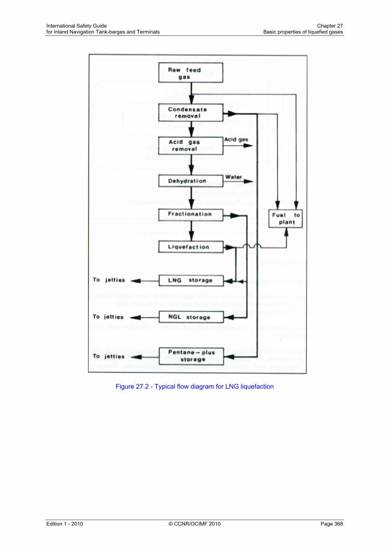
Natural gas contains smaller quantities of heavier hydrocarbons (collectively known as natural gas liquids – NGLs). This is in addition to varying amounts of water, carbon dioxide, nitrogen and other non-hydrocarbon substances. These relationships are shown in Figure 27.1 The proportion of NGL contained in raw natural gas varies from one location to another. However, NGL percentages are generally smaller in gas wells when compared with those found in condensate reservoirs or that associated with crude oil. Regardless of origin, natural gas requires treatment to remove heavier hydrocarbons and non-hydrocarbon constituents. This ensures that the product is in an acceptable condition for liquefaction or for use as a gaseous fuel. Figure 27.2 is a typical flow diagram for a liquefaction plant used to produce liquefied natural gas (LNG). The raw feed gas is first stripped of condensates. This is followed by the removal of acid gases (carbon dioxide and hydrogen sulphide). Carbon dioxide must be removed as it freezes at a temperature above the atmospheric boiling point of LNG and the toxic compound hydrogen sulphide is removed as it causes atmospheric pollution when being burned in a fuel. Acid gas removal saturates the gas stream with water vapour and this is then removed by the dehydration unit. The gas then passes to a fractionating unit where the NGLs are removed and further split into propane and butane. Finally, the main gas flow, now mostly methane, is liquefied into the end product, liquefied natural gas (LNG).
International Safety Guide Chapter 27 for Inland Navigation Tank-barges and Terminals Basic properties of liquefied gases
Edition 1 - 2010 © CCNR/OCIMF 2010 Page 368
Figure 27.2 - Typical flow diagram for LNG liquefaction

International Safety Guide Chapter 27 for Inland Navigation Tank-barges and Terminals Basic properties of liquefied gases
Edition 1 - 2010 © CCNR/OCIMF 2010 Page 369
To lower temperature of the methane gas to about –162°C (its atmospheric boiling point) there are three basic liquefaction processes in current use. These are outlined below:- • Pure refrigerant cascade process- this is similar in principle to the cascade
reliquefaction cycle described in Section 31.5 but in order to reach the low temperature required, three stages are involved, each having its own refrigerant, compressor and heat exchangers. The first cooling stage utilises propane, the second is a condensation stage utilising ethylene and, finally, a sub-cooling stage utilising methane is involved. The cascade process is used in plants commissioned before 1970.
• Mixed refrigerant process – whereas with pure refrigerant process (as described above) a series of separate cycles are involved, with the mixed refrigerant process (usually methane, ethane propane, and nitrogen), the entire process is achieved in one cycle. The equipment is less complex than the pure refrigerant cascade process but power consumption is substantially greater and for this reason its use is not widespread.
• Pre-cooled mixed refrigerant process – this process is generally known as the MCR process (Multi-Component Refrigerant) and is a combination of the pure refrigerant cascade and mixed refrigerant cycles. It is by far the most common process in use today.
Fuel for the plant is provided mainly by flash-off gas from the reliquefaction process but boil-off from LNG storage tanks can also be used. If necessary, additional fuel may be taken from raw feed gas or from extracted condensates. Depending upon the characteristics of the LNG to be produced and the requirements of the trade, some of the extracted NGLs may be re-injected into the LNG stream.
27.2.2 LPG Production Liquefied petroleum gas (LPG) is the general name given for propane, butane and mixtures of the two. These products can be obtained from the refining of crude oil. When produced in this way they are usually manufactured in pressurised form. However, the main production of LPG is found within petroleum producing countries. At these locations, LPG is extracted from natural gas or crude oil streams coming from underground reservoirs. In the case of natural gas well, the raw product consists mainly of methane. However, as shown in Figure 27.2, in this process it is normal for NGLs to be produced and LPG may be extracted from them as a by-product. A simple flow diagram which illustrates the production of propane and butane from oil and gas reservoirs is shown in Figure 27.3. In this example the methane and ethane which have been removed are used by the terminal’s power station, and the LPG’s, after fractionation and chill-down, are pumped to terminal storage tanks prior to shipment for export.

International Safety Guide Chapter 27 for Inland Navigation Tank-barges and Terminals Basic properties of liquefied gases
Edition 1 - 2010 © CCNR/OCIMF 2010 Page 370
Figure 27.3 - Typical oil/gas flow diagram
International Safety Guide Chapter 27 for Inland Navigation Tank-barges and Terminals Basic properties of liquefied gases
Edition 1 - 2010 © CCNR/OCIMF 2010 Page 371
27.2.3 Production of Chemical Gases
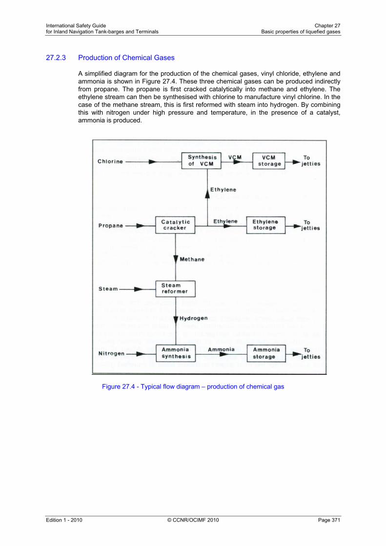
A simplified diagram for the production of the chemical gases, vinyl chloride, ethylene and ammonia is shown in Figure 27.4. These three chemical gases can be produced indirectly from propane. The propane is first cracked catalytically into methane and ethylene. The ethylene stream can then be synthesised with chlorine to manufacture vinyl chlorine. In the case of the methane stream, this is first reformed with steam into hydrogen. By combining this with nitrogen under high pressure and temperature, in the presence of a catalyst, ammonia is produced.
Figure 27.4 - Typical flow diagram – production of chemical gas

International Safety Guide Chapter 27 for Inland Navigation Tank-barges and Terminals Basic properties of liquefied gases
Edition 1 - 2010 © CCNR/OCIMF 2010 Page 372
27.2.4 The Principal Products
Whilst the hydrocarbon gases methane, ethane, propane and butane may be regarded principally as fuels, the LPGs are also important as feedstock in the production of the chemical gases. Liquefied Natural Gas (LNG) Natural gas is transported either by pipeline as a gas or by sea in its liquefied form as LNG. Natural gas comes from underground deposits as described in 27.2.1. Its composition varies according to where it is found but methane is by far the predominant constituent, ranging from 70 per cent to 99 per cent. Natural gas is now a major commodity in the world energy market. Natural Gas Liquids (NGLs) Associated gas, found in combination with crude oil, comprises mainly methane and NGLs. As shown in Figure 27.1, the NGLs are made up of ethane, LPGs and gasoline. A small number of terminals, including several facilities in Europe, have the ability to strip methane from the gas stream and to load raw NGLs onto semi-pressurised gas carriers. These tankers are modified with additional compressor capacity for shipment to customers able to accept such ethane-rich cargoes. These NGLs are carried at -80°C at atmospheric pressure or at -45°C at a vapour pressure of 5 bar. The Liquefied Petroleum Gases (LPG) The liquefied petroleum gases comprise propane, butane and mixtures of the two. Butane stored in cylinders and thus known as bottled gas, has widespread use as a fuel for heating and cooking in remote locations. However, it is also an important octane enhancer for motor gasoline and a key petrochemical feedstock. Propane, too, is utilised as a bottled gas, especially in cold climates (to which its vapour pressure is more suited). However, LPG is mainly used in power generation, for industrial purposes such as metal cutting and as a petrochemical feedstock. Ammonia With increased pressure on the world’s food resources, the demand for nitrogen-containing fertilisers, based on ammonia, expanded strongly during the 1970s and 1980s. Large-scale ammonia plants continue to be built in locations rich in natural gas which is the raw material most commonly used to make this product. Ammonia is also used as an on-shore industrial refrigerant, in the production of explosives and for numerous industrial chemicals such as urea. Ethylene Ethylene is one of the primary petrochemical building blocks. It is used in the manufacture of polyethylene plastics, ethyl alcohol, polyvinyl chlorine (PVC), antifreeze, polystyrene and polyester fibres. It is obtained by cracking either naphtha, ethane or LPG.

International Safety Guide Chapter 27 for Inland Navigation Tank-barges and Terminals Basic properties of liquefied gases
Edition 1 - 2010 © CCNR/OCIMF 2010 Page 373
Propylene Propylene is a petrochemical intermediate used to make polypropylene and polyurethane plastics, acrylic fibres and industrial solvents. Butadiene Butadiene is a highly reactive petrochemical intermediate. It is used to produce styrene, acrylonitrile and polybatudiene synthetic rubbers. Butadiene is also used in paints and binders for non-woven fabrics and, as an intermediate, in plastic and nylon production. Most butadiene output stems from the cracking of naphtha to produce ethylene. Vinyl chloride Vinyl chloride is an easily liquefiable, chlorinated gas used in the manufacture of PVC, the second most important thermoplastic in the world in terms of output. Vinyl chlorine not only has a relatively high boiling point, at –14°C, but is also, with a specific gravity of 0.90, much denser than the other common gas carrier cargoes. Carbon dioxide Carbon dioxide is a colourless, odorless gas. When inhaled at concentrations much higher than usual atmospheric levels, it can produce a sour taste in the mouth and a stinging sensation in the nose and throat. These effects result from the gas dissolving in the mucous membranes and saliva, forming a weak solution of carbonic acid. This sensation can also occur during an attempt to stifle a burp after drinking a carbonated beverage. Amounts above 5,000 ppm are considered very unhealthy, and those above about 50,000 ppm (equal to 5% by volume) are considered dangerous to animal life. At standard temperature and pressure, the density of carbon dioxide is approximately 1.98 kg/m3, about 1.5 times that of air. The carbon dioxide molecule (O=C=O) contains two double bonds and has a linear shape. It has no electrical dipole, and as it is fully oxidised, it is moderately reactive and is non-flammable, but will support the combustion of metals such as magnesium. At −78.51°C, carbon dioxide changes directly from a solid phase to a gaseous phase through sublimation, or from gaseous to solid through deposition. Solid carbon dioxide is normally called "dry ice", a generic trademark. It was first observed in 1825 by the French chemist Charles Thilorier. Dry ice is commonly used as a cooling agent, and it is relatively inexpensive. A convenient property for this purpose is that solid carbon dioxide sublimes directly into the gas phase leaving no liquid. It can often be found in grocery stores and laboratories, and it is also used in the shipping industry. The largest non-cooling use for dry ice is blast cleaning. Liquid carbon dioxide forms only at pressures above 5.1 atm; the triple point of carbon dioxide is about 518 kPa at −56.6°C. The critical point is 7.38 MPa at 31.1°C.
International Safety Guide Chapter 27 for Inland Navigation Tank-barges and Terminals Basic properties of liquefied gases
Edition 1 - 2010 © CCNR/OCIMF 2010 Page 374
27.3 Chemical Structure of Gases
Chemical compounds with the same chemical structure are often known by different names. An alternative name given to the same compound is called a synonym. Table 27.1 gives a list of the synonyms of the main liquefied gases against each common name and its simple formula. The more complex compounds tend to have a larger number of synonyms than the simple compounds. The simple chemical formula, as shown in Table 27.1, gives the ratio of atoms of each element in the compound. Since a molecule is the smallest part of the compound which exhibits all the chemical properties of that specific material, this formula is often referred to as the molecular formula. Hydrocarbons are substances whose molecules contain only hydrogen and carbon atoms. The molecules can be in various arrangements and the products may be gases, liquids or solids at ambient temperatures and pressures, depending upon the number of the carbon atoms in the molecular structure. Generally, those hydrocarbons with up to four carbon atoms are gaseous at ambient conditions and comprise the hydrocarbon liquefied gases. Hydrocarbons with five up to about twenty carbon atoms are liquid at ambient conditions and those with more carbon atoms are solid. The carbon atom has four bonds which can unite with other carbon atoms or with atoms of other elements. A hydrogen atom, however, has only one bond and can unite with only one other atom. Where the relative numbers of carbon and hydrogen atoms in a hydrocarbon molecule permit the carbon atoms to use their bonds singly to other carbon atoms, the molecule is said to be saturated. Figure 27.1 illustrates the saturated molecular structure of iso-butane (i-butane) and normal butane (n-butane). Examination of these examples shows that, for saturated hydrocarbons, the proportion of carbon and hydrogen atoms in the molecule is in accordance with the formula CnH2n+2. Thus, methane (CH4), ethane (C2H6), and propane (C3H8) are all saturated hydrocarbons. Where there is less than the full complement of hydrogen atoms, as given by the above formula, two or more carbon atoms become inter-linked by double or triple bonds. For this reason they are called unsaturated. These links between carbon atoms are weaker than single bonds, with the result that such compounds are chemically more reactive than the single-bonded compounds.

International Safety Guide Chapter 27 for Inland Navigation Tank-barges and Terminals Basic properties of liquefied gases
Edition 1 - 2010 © CCNR/OCIMF 2010 Page 375
Common Name Simple Formula Synonyms
Methane CH4 Fire damp; marsh gas; natural gas; LNG
Ethane C2H6 Bimethyl; dimethyl; methyl methane
Propane C3H8 –
n-Butane C4H10 Normal-butane
i-Butane C4H10 Iso-butane; 2-methlypropane
Ethylene C2H4 Ethene
Propylene C3H6 Propene
α-Butylene C4H8 But-1-ene; ethyl ethylene
β-Butylene C4H8 But-2-ene; dimethyl ethylene; pseudo butylenes
γ-Butylene C4H8 Isobutene; 2-methylprop-2-ene
Butadiene C4H6 b.d.; bivinyl; 1,3 butadiene; butadiene 1-3; divinyl; biethylene; erythrene; vinyl ethylene
Isoprene C5H8 3-methyl – 1,3 butadiene; 2-methyl – 1,3 butadiene; 2-methylbutadiene – 1,3
Vinyl chloride C2H3CI Chloroethene; chloroethylene; VCM; Vinyl chloride monomer
Ethylene oxide C2H4O Dimethylene oxide; EO; 1,2 epoxyethane; oxirane
Propylene oxide C3H6O 1,2 epoxy propane; methyl oxirane; propene oxide
Ammonia NH3 Anhydrous ammonia; ammonia gas; liquefied ammonia; liquid ammonia
Table 27.1 - Synonyms for the main liquefied gases
Note: Commercial propane contains some butane; similarly, commercial butane contains some propane. Both may contain impurities such as ethane and pentane, depending on their permitted commercial specification. Some further data on mixtures is given in Sections 27.19 and 27.20.

International Safety Guide Chapter 27 for Inland Navigation Tank-barges and Terminals Basic properties of liquefied gases
Edition 1 - 2010 © CCNR/OCIMF 2010 Page 376
Figure 27.5 - Molecular structure of some saturated hydrocarbons (single bonds)
Figure 27.6 - Molecular structure of some unsaturated hydrocarbons (double bonds)
International Safety Guide Chapter 27 for Inland Navigation Tank-barges and Terminals Basic properties of liquefied gases
Edition 1 - 2010 © CCNR/OCIMF 2010 Page 377
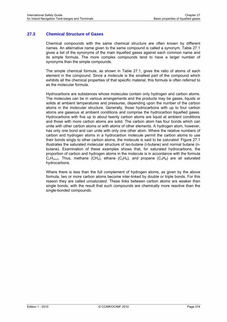
Figure 27.6 illustrates the molecular structure of two such unsaturated hydrocarbons, propylene (C3H6), and butadiene (C4H6). Ethylene (C2H4) is a further example of an unsaturated hydrocarbon. The third group of liquefied gases consists of the chemical gases. These are characterised by additional atoms other than carbon and hydrogen. Figure 27.7 illustrates the molecular structure of two such compounds, propylene oxide (C3H6O) and vinyl chloride (C2H3CI). Most compounds in this grouping are chemically reactive.
Figure 27.7 - Molecular structure of some chemical gases
27.4 Saturated and Unsaturated Hydrocarbons Saturated hydrocarbons The saturated hydrocarbons, methane, ethane, propane and butane are all colourless and odourless liquids. They are all flammable gases and will burn in air or oxygen to produce carbon dioxide and water vapour. They do not present chemical compatibility problems when in contact with the construction materials commonly encountered in gas handling. In the presence of moisture, however, the saturated hydrocarbons may form hydrates (see Section 27.9). Unsaturated hydrocarbons The unsaturated hydrocarbons, ethylene, propylene, butylene, butadiene and isoprene are colourless liquids with a faint, sweetish odour. Like the saturated hydrocarbons they are all flammable in air or oxygen, producing carbon dioxide and water vapour. They are more reactive, from a chemical viewpoint, than the saturated hydrocarbons and may react dangerously with chlorine. Ethylene, propylene and butylene do not present chemical compatibility problems with materials of construction, whereas butadiene and isoprene, each having two pairs of double bonds, are by far the most reactive within this family. They may react with air to form unstable peroxides which tend to induce polymerisation (see Section 27.8). Butadiene is incompatible in the chemical sense with copper, silver, mercury, magnesium, aluminium and monel. During production, butadiene streams often contain traces of acetylene which can react with brass and copper to form explosive acetylides.

International Safety Guide Chapter 27 for Inland Navigation Tank-barges and Terminals Basic properties of liquefied gases
Edition 1 - 2010 © CCNR/OCIMF 2010 Page 378
Water is soluble in butadiene, particularly at high temperatures and Figure 27.8 illustrates this effect. In this diagram the figures quoted are for the purpose of illustration only. As can be seen, on cooling water-saturated butadiene, the solubility of the water decreases and water will separate out as droplets which settle as a layer in the bottom of the tank. For instance, on cooling water-saturated butadiene from +15°C to +5°C approximately 100 parts per million of free water separates out. On this basis, for a 1,000 m3 tank, 0.1 m3 of free water would require to be drained from the bottom of the tank. On further cooling to below zero, this layer of water would increase in depth and freeze.
Figure 27.8 - Solubility of water in butadiene
27.5 The Chemical Gases
The chemical gases commonly transported in liquefied gas carriers are ammonia, vinyl chloride, ethylene oxide and propylene oxide. Apart from the latter two examples, since these gases do not belong to one particular family, their chemical properties vary considerably. Ammonia is a colourless alkaline liquid with a pungent odour. The vapours of ammonia are flammable and burn with a yellow flame, forming water vapour and nitrogen. However, ammonia vapour in air requires a high concentration (14 – 28 per cent) to be flammable, has a high ignition energy requirement (600 times that for propane) and burns with low combustion energy. For these reasons, the Gas Codes, while requiring full attention to the avoidance of ignition sources, do not require flammable gas detection in the hold or interbarrier spaces. Nevertheless, ammonia must always be regarded as a flammable cargo.

International Safety Guide Chapter 27 for Inland Navigation Tank-barges and Terminals Basic properties of liquefied gases
Edition 1 - 2010 © CCNR/OCIMF 2010 Page 379
Ammonia is toxic and highly reactive. It can form explosive compounds with mercury, chlorine, iodine, bromine, calcium, silver oxide and silver hypochlorite. Ammonia vapour is extremely soluble in water and will be absorbed rapidly and exothermically to produce a strong alkaline solution of ammonium hydroxide. One volume of water will absorb approximately 200 volumes of ammonia vapour. For this reason it is unsafe to introduce water into a tank containing ammonia vapour, as this can result in a vacuum condition rapidly developing within the tank. (See also Section 32.9.5) Since ammonia is alkaline, ammonia vapour/air mixtures may cause stress corrosion on cargo tank shells. The factors contributing to stress corrosion cracking are the material of construction, residual stress within structures (from tank fabrication) and the nature of the cargo (including its temperature, pressure and impurities). Stress corrosion cracking occurs as a result of a chemical reaction and thus will happen faster at higher temperatures. Stress corrosion cracking is identified as cracking in a containment vessel where (typically) fine cracks may be formed in many directions. Cracks caused by stress corrosion cracking are usually fine and brittle in nature. The risk of stress corrosion cracking occurring can be reduced by the following measures: • The provision of refrigerated storage at a temperature of below –30°C. • During construction, by using steels having a low yield strength. • During construction, by having tank welds stress-relieved by thermal methods. • Adding 0.2 per cent water to the ammonia. • Developing procedures to minimise the ammonia being contaminated with air. Because of ammonia’s highly reactive nature, copper alloys, aluminium alloys, galvanised surfaces, phenolic resins, polyvinyl chloride, polyesters and viton rubbers are unsuitable for ammonia service. Mild steel, stainless steel, neoprene rubber and polythene are, however, suitable. Vinyl chloride is a colourless liquid with a characteristic sweet odour. It is highly reactive, though not with water, and may polymerise in the presence of oxygen, heat and light. Its vapours are highly toxic and flammable. Aluminium alloys, copper, silver, mercury and magnesium are unsuitable for vinyl chloride service. Steels are, however, chemically compatible. Ethylene oxide and propylene oxide are colourless liquids with an ether-like odour. They are flammable, toxic and highly reactive. Both polymerise; ethylene oxide does so more readily than propylene oxide, particularly in the presence of air or impurities. Both gases may react dangerously with ammonia. Cast iron, mercury, aluminium alloys, copper and alloys of copper, silver and its alloys, magnesium and some stainless steels are unsuitable for the handling of ethylene oxide. Mild steel and certain other stainless steels are suitable as tank shell construction materials for both ethylene and propylene oxides.
International Safety Guide Chapter 27 for Inland Navigation Tank-barges and Terminals Basic properties of liquefied gases
Edition 1 - 2010 © CCNR/OCIMF 2010 Page 380
Chlorine is a much less frequently carried cargo and restricted to special tankers. It is a yellow liquid which evolves a green vapour. It has a pungent and irritating odour and is highly toxic. It is non-flammable but it can support combustion of other flammable materials in much the same way as oxygen. It is soluble in water forming a highly corrosive acidic solution and can form dangerous reactions with all the other liquefied gases. In the moist condition, because of its corrosivity, it is difficult to contain. Dry chlorine is compatible with mild steel, stainless steel, monel and copper. Chlorine is very soluble in caustic soda solution which can be used to absorb chlorine vapour.
27.6 Chemical Properties The chemical properties and compatibilities of many liquefied gases are summarised in Tables 27.2, 27.3(a) and 27.3(b).

International Safety Guide Chapter 27 for Inland Navigation Tank-barges and Terminals Basic properties of liquefied gases
Edition 1 - 2010 © CCNR/OCIMF 2010 Page 381
Met
hane
Etha
ne
Prop
ane
Buta
ne
Eth
ylen
e
Prop
ylen
e
But
ylen
e
Buta
dien
e
Isop
rene
Am
mon
ia
Vin
yl c
hlor
ide
Eth
ylen
e ox
ide
Prop
ylen
e ox
ide
Chl
orin
e
Flammable X X X X X X X X X X X X X
Toxic X X X X X X
Polymerisable X X X X
REACTIVE WITH
Magnesium X X X X
Mercury X X X X X X
Zinc X X
Copper X X X X X
Aluminium X X X X X X X
Mild carbon steel X3 X1
Stainless steel X2
Iron X X
PTFE* X
PVC† X
Polyethylene X3 X X X X
Ethanol X
Methanol X
Table 27.2 - Chemical properties of liquefied gases
Notes:‘ Study can be made to the data sheets in the the IGC Code for further details on chemical reactivity.
1 Stainless steel containing 9 per cent nickel is the usual containment material for ethylene. 2 Refer to IGC Code – Section 17.16.3 3 Not suitable with liquid methane due to brittle fracture.
* PTFE:– polytetrafluoroethylene (jointing material) † PVC:– polyvinyl chloride (electric cable insulation)

International Safety Guide Chapter 27 for Inland Navigation Tank-barges and Terminals Basic properties of liquefied gases
Edition 1 - 2010 © CCNR/OCIMF 2010 Page 382
Carbon dioxide
X
Oxygen or Air
X
X
X
X
Water vapour
X
X
X
Chlorine X
X
X
X
X
X
X
X
X
X
X
X
Propylene oxide
X
Ethylene oxide
X
X
Vinyl chloride
X
X
Ammonia
X
X
X
X
Isoprene
X
X
X
Butadiene
X
X
X
Butylene
X
Propylene
X
Ethylene
X
Butane
X
Propane
X
Ethane
X
Methane
X
Met
hane
Etha
ne
Prop
ane
Buta
ne
Eth
ylen
e
Prop
ylen
e
But
ylen
e
Buta
dien
e
Isop
rene
Amm
onia
Viny
l chl
orid
e
Eth
ylen
e ox
ide
Prop
ylen
e ox
ide
Chl
orin
e
Wat
er v
apou
r
Oxy
gen
or A
ir
Car
bon
diox
ide
Table 27.3(a) - Chemical compatibilities of liquefied gases X = incompatible

International Safety Guide Chapter 27 for Inland Navigation Tank-barges and Terminals Basic properties of liquefied gases
Edition 1 - 2010 © CCNR/OCIMF 2010 Page 383
*These cargoes are mixtures of various liquefied gases and are not listed in the IGC Code.
Table 27.3(b) - Previous cargo compatibilities of liquefied gases
Code Description W Water wash V Visual Inspection N2 Inert with Nitrogen only N2I Inert with Nitrogen or Inert Gas ET Empty Tank: which means as far as the pumps can go S Standard Requirements: cargo tanks and cargo piping to be liquid free and 0.5 bar
overpressure (ship-type dependant) prior to loading, but based on terminal or independent cargo surveyor’s advice.
Note: Before any inerting starts the tank bottom temperature should be heated to about 0°C
Note: A cargo tank should not be opened for inspection until the tank temperature is close to ambient conditions.

International Safety Guide Chapter 27 for Inland Navigation Tank-barges and Terminals Basic properties of liquefied gases
Edition 1 - 2010 © CCNR/OCIMF 2010 Page 384
27.7 Inert Gas and Nitrogen
Inert gas is used on gas carriers to inert cargo tanks and on some type of tankers to maintain positive pressures in hold and interbarrier spaces (see Sections 31.7, 32.2.3, 32.9.3). This is carried out in order to prevent the formation of flammable mixtures. For cargo tanks the inerting operation is a necessary preliminary prior to aerating for inspection or drydock but it can be time-consuming. Inerting is also required before moving from a gas-free condition into the loaded condition. Regarding inerting levels, prior to gassing-up, a tank should have an oxygen content of less than 5 per cent but normally a lower figure is required by loading terminals. Prior to aeration, the inerting process should have achieved an hydrocarbon content of below 2 per cent. In addition to oxygen, another essential element regarding inert gas quality is its dryness. Any moisture contained within the gas can condense at the cold cargo temperatures encountered. Therefore, in order to prevent hydrate formation in the products loaded and to prevent serious condensation and corrosion in tanks and hold spaces, inert gas is thoroughly dried as it leaves the generator. Each type of inert gas (fuel burning, shipboard nitrogen production, or pure nitrogen from the shore) has its own particular use. Throughout this Guide the term inert gas is used for a gas produced by a combustion inert gas generator. The use of the word nitrogen can mean inert gas without carbon dioxide but with some oxygen present (as for shipboard production systems) or it can relate to the pure nitrogen used for special inerting prior to loading an oxygen critical cargo.
Component Inert Gas by combustion Nitrogen Membrane Separating Process
Nitrogen 85 to 89% Up to 99.5%
Carbon dioxide 14% -
Carbon monoxide 0.1% (max) -
Oxygen 1 to 3% > 0.5%
Sulphur oxides 0.1% -
Oxides of Nitrogen traces -
Dew point – 45°C – 65°C
Ash & Soot present -
Density (Air = 1.00) 1.035 0.9672
Table 27.4 - Inert gas compositions

International Safety Guide Chapter 27 for Inland Navigation Tank-barges and Terminals Basic properties of liquefied gases
Edition 1 - 2010 © CCNR/OCIMF 2010 Page 385
Only nitrogen of high purity is fully compatible, in the chemical sense, with all the liquefied gases. Many components of combustion-generated inert gas can put the liquefied chemical gases off specification. In particular, as far as personal safety and chemical reactivity are concerned, the following points regarding the constituents of inert gas should be noted: Carbon particles in the form of ash and soot can put many chemical gases off specification. Carbon dioxide will freeze at temperatures below –55°C thus contaminating the cargo if carriage temperatures are particularly low, such as in the case of ethylene. Carbon dioxide will also contaminate ammonia cargoes by reacting to produce carbamates. Both solid carbon dioxide and carbamate formation result in cargo contamination and operational difficulties, such as clogging of pumps, filters and valves. Carbon dioxide can also act as a catalyst in complicated chemical reactions with sulphur compounds in some LPG cargoes. Carbon monoxide, if generated in sufficient quantities, can cause difficulties during any subsequent aeration operation. When aeration is thought complete, the levels of toxic carbon monoxide may still be unacceptable from the aspect of personal safety. (It should be noted that carbon monoxide has a TLV-TWA of 50 parts per million.) Moisture in inert gas can condense and in so doing hydrates can form in cargoes and inerted spaces can suffer from severe corrosion. When cold cargo is to be loaded, it is therefore important that the inert gas in cargo tanks has a sufficiently low dew point to avoid any water vapour freezing out and other operational difficulties. Furthermore, moisture can create difficulties particularly with butadiene, isoprene, ammonia and chlorine cargoes. Oxygen even in the small percentages found in shipboard produced inert gas is incompatible with butadiene, isoprene, vinyl chloride and ethylene oxide. In contact with oxygen, these cargoes may combine to form peroxides and polymers. For the foregoing reasons, only pure nitrogen taken from the shore can be considered to be fully inert, in the chemical sense, for all the liquefied gases. Nevertheless, for the inerting of hold spaces and cargo tanks on tankers carrying LPG cargoes at temperatures down to about –48°C, inert gas generation by good quality fuel burning under carefully controlled combustion or by the air separation process can provide an inert gas of acceptable quality.
27.8 Polymerisation While many of the liquefied gases are polymerisable (as indicated by a double bond in their molecular structure), cargo polymerisation difficulties only arise in practice in the case of butadiene, isoprene, ethylene oxide and vinyl chloride. Polymerisation may be dangerous under some circumstances, but can be delayed or controlled by the addition of inhibitors. Polymerisation takes place when a single molecule (a monomer) reacts with another molecule of the same substance to form a dimer. This process can continue until a long-chain molecule is formed, possibly having many thousands of individual molecules (a polymer). The mechanism is illustrated for vinyl chloride in Figure 27.9. The process can be very rapid and involves the generation of a great deal of heat. It may be initiated spontaneously or may be catalysed by the presence of oxygen (or other impurities) or by heat transfer during cargo operations (see also Section 32.6). During polymerisation, the cargo becomes more viscous until, finally, a solid and unpumpable polymer may be formed.

International Safety Guide Chapter 27 for Inland Navigation Tank-barges and Terminals Basic properties of liquefied gases
Edition 1 - 2010 © CCNR/OCIMF 2010 Page 386
Polymerisation may be prevented, or at least the rate of polymerisation may be reduced, by adding a suitable inhibitor to the cargo. However, if polymerisation starts, the inhibitor will be consumed gradually until a point is reached when polymerisation may continue unchecked. In the case of butadiene, tertiary butyl catechol (TBC) is added primarily as an anti-oxidant but, in the absence of oxygen, it can also act, to a limited extent, as an inhibitor. The difference between the vapour pressure of an inhibitor and its cargo has an important bearing on the effectiveness of the inhibitor. Generally, inhibitors have a vapour pressure lower than the cargo in which they sit. Accordingly, the greatest protection is provided in the liquid. This leaves the gases in the vapour space relatively unprotected. It follows therefore that condensation in the vapour space can suffer from increased rates of polymerisation and problems have been known to occur in these areas.
Figure 27.9 - The polymerisation of vinyl chloride Inhibitors can be toxic. Those most commonly used are hydroquinone (HQ) and TBC. Health and safety data for these products is included in Section 28.1. As will be noted, care should be taken when handling inhibitors and cargoes with inhibitor added.

International Safety Guide Chapter 27 for Inland Navigation Tank-barges and Terminals Basic properties of liquefied gases
Edition 1 - 2010 © CCNR/OCIMF 2010 Page 387
Tankers’ personnel should ensure that an Inhibitor Information Form is received from the cargo shipper before departure from the loading port. This certificate should provide the information shown in the figure below:—
LIQUEFIED GAS – INHIBITOR INFORMATION FORM
To be completed before loading an inhibited cargo
SHIP.......................................................... DATE ............................................................
PORT & BERTH ...................................... TIME .............................................................
1. CORRECT TECHNICAL NAME OF CARGO ................................................................
2. CORRECT TECHNICAL NAME OF INHIBITOR ......................................................................................................................
3. AMOUNT OF INHIBITOR ADDED .................................................................................
4. DATE ADDED .................................................................................................................
5. EXPECTED LIFETIME OF INHIBITOR ..........................................................................
6. ANY TEMPERATURE LIMITATIONS AFFECTING INHIBITOR ...................................
7. ACTION TO BE TAKEN IF VOYAGE EXCEEDS EFFECTIVE LIFETIME OF INHIBITOR ......................................................................................................................
IIF THE ABOVE INFORMATION IS NOT SUPPLIED, THE CARGO SHOULD BE REFUSED
FOR SHIP ................................................ FOR SHORE ................................................ (Signed) (Signed)
Liquefied gas – inhibitor information form
Figure 27.9(a) - Inhibitor information form In addition, the quantity of inhibitor required for effective inhibition and the toxic properties of the inhibitor should be advised. A similar but more difficult reaction to control is known as dimerisation. This cannot be stopped by inhibitors or any other means. The only way to avoid or slow down dimerisation is to keep the cargo as cool as possible and such cooling is recommended, especially during longer voyages.
27.9 Hydrate Formation Propane and butane may form hydrates under certain conditions of temperature and pressure in the presence of free water. This water may be present in LPG as an impurity or may be extracted from cargo tank bulkheads if rust is present. Rust which has been dehydrated in this way by LPG loses its powers of adhesion to tank surfaces and may settle to the tank bottom as a fine powder. LPG hydrates are white crystalline solids which may block filters and reliquefaction regulating valves. Furthermore they may damage cargo pumps.

International Safety Guide Chapter 27 for Inland Navigation Tank-barges and Terminals Basic properties of liquefied gases
Edition 1 - 2010 © CCNR/OCIMF 2010 Page 388
Hydrate inhibitors such as methanol or ethanol may be added at suitable points in the system but nothing whatsoever should be added without the consent of the shipper and ship operator. It should be noted that in some countries the use of methanol is banned. In addition, some chemical gases may be put off specification by the addition of methanol. Care must be taken if a hydrate inhibitor is added to a polymerisable cargo as the polymer inhibition mechanism may be negated. Since methanol is toxic, care should be taken regarding its safe handling.
27.10 Lubrication
The property of a fluid which restricts one layer of the fluid moving over an adjacent layer is called viscosity. Viscosity is important in determining the lubricating properties of liquid. The majority of liquefied gases have poor lubricating properties by comparison with lubricating oils or even water and this is shown in Table 27.4(a).
Liquid (temperature)
Lub oil (at +70°C)
Water (at +100°C)
Propane (at –45°C)
Viscosity (centipoise) 28.2 0.282 0.216
Specific Heat (kcal/kg °C)
0.7 1.0 0.5
Latent Heat of Vaporisation (kcal/kg)
35 539 101
Table 27.4(a) - Factors affecting lubrication
Liquefied hydrocarbon gases can dissolve in lubricating oil and, for certain applications, such admixture can result in inadequate lubrication of pump seals and compressors. The solvent action of liquefied gases on grease can cause the degreasing of mechanical parts with similar loss of lubrication in fittings such as valves. In addition to low viscosity, liquefied gas has relatively poor cooling properties and liquids are not able to carry heat away from a shaft bearing very effectively. Any excessive heat will result in a relatively rapid rise in temperature of the bearing. (Specific heat of propane is about half that of water). Under these circumstances, the liquid will vaporise when its vapour pressure exceeds the product pressure in the bearing. The vapour will expel liquid from the bearing and result in bearing failure due to overheating. It should also be noted that the lubricating oil used in a compressor must be compatible with the grade of cargo being carried (see Section 32.6.1).

International Safety Guide Chapter 27 for Inland Navigation Tank-barges and Terminals Basic properties of liquefied gases
Edition 1 - 2010 © CCNR/OCIMF 2010 Page 389
27.11 Physical Properties
The physical properties of a liquefied gas depend on its molecular structure. Some compounds have the same molecular formula, but the ways in which the atoms are arranged within the molecule may be different. These different compounds of the same basic substance are called isomers. They have the same molecular mass but differing physical and chemical properties. Examples are n-butane and iso-butane, shown in Figure 27.5. The principal physical properties of the main liquefied gases are listed in Table 27.5. From this data the different physical properties of the isomers of butane and butylene should be noted. The most important physical property of a liquefied gas is its saturated vapour pressure/temperature relationship. This property, which will be studied in detail later, governs the design of the tank containment system best suited to each cargo and has a strong influence on economic considerations.
27.12 States of Matter
27.12.1 Solids, Liquids and Gases Most substances can exist in either the solid, liquid or vapour state. In changing from solid to liquid (fusion) or from liquid to vapour (vaporisation), heat must be given to the substance. Similarly, in changing from vapour to liquid (condensation) or from liquid to solid (solidification), the substance must give up heat. The heat given to or given up by the substance in changing state is called latent heat. For a given mass of the substance the latent heats of fusion and solidification are the same. Similarly, the latent heats of vaporisation and of condensation are the same, although of different values from the latent heat of fusion or solidification.
Figure 27.10 - Temperature/heat diagram for varying states of matter

International Safety Guide Chapter 27 for Inland Navigation Tank-barges and Terminals Basic properties of liquefied gases
Edition 1 - 2010 © CCNR/OCIMF 2010 Page 390
Fusion or solidification occurs at a specific temperature for each substance and this temperature is virtually independent of the pressure. However, vaporisation or condensation of a pure substance occurs at a temperature which varies widely depending upon the pressure exerted. It should also be noted that the latent heat of vaporisation varies with pressure. Figure 27.10 illustrates these temperature/heat relationships as a substance is heated or cooled through its three states: here the temperatures of fusion or solidification (A) and of vaporisation or condensation (B) are shown. For liquefied gases, the solid state is not of concern since this can only occur at temperatures well below those at which such gases are carried. However, temperatures, pressures and latent heats of vaporisation are of fundamental importance.
Gas Atmospheric boiling point
(°C)
Critical temperature
(°C)
Critical pressure
(bars, absolute)
Condensing ratio
dm3 liquid _____________
1m3 gas
Liquid relative density
at Atm. Boiling Pt.
(Water = 1)
Vapour relative density (Air = 1)
Methane –161.5 –82.5 44.7 0.804 0.427 0.554
Ethane – 88.6 32.1 48.9 2.453 0.540 1.048
Propane – 42.3 96.8 42.6 3.380 0.583 1.55
n-Butane – 0.5 153 38.1 4.32 0.600 2.09
i-Butane – 11.7 133.7 38.2 4.36 0.596 2.07
Ethylene –103.9 9.9 50.5 2.20 0.570 0.975
Propylene – 47.7 92.1 45.6 3.08 0.613 1.48
α-Butylene – 6.1 146.4 38.9 4.01 0.624 1.94
γ-Butylene – 6.9 144.7 38.7 4.00 0.627 1.94
Butadiene – 5.0 161.8 43.2 3.81 0.653 1.88
Isoprene 34 211.0 38.5 0.67 2.3
Vinyl chloride
– 13.8 158.4 52.9 2.87 0.965 2.15
Ethylene oxide
10.7 195.7 74.4 2.13 0.896 1.52
Propylene oxide
34.2 209.1 47.7 0.830 2.00
Ammonia – 33.4 132.4 113.0 1.12 0.683 0.597
Chlorine – 34 144 77.1 2.03 1.56 2.49
Table 27.5 - Physical properties of gases
International Safety Guide Chapter 27 for Inland Navigation Tank-barges and Terminals Basic properties of liquefied gases
Edition 1 - 2010 © CCNR/OCIMF 2010 Page 391
27.12.2 Spillage of Liquefied Gas
It is convenient here, against the background of the preceding paragraphs, to consider what happens when a liquefied gas is spilled. Firstly, consider the escape from its containment of a fully refrigerated liquid. Here the liquid is already at or near atmospheric pressure but, on escape, it is brought immediately into contact with the ground or water at ambient temperature. The temperature difference between the cold liquid and the material it contacts provides an immediate heat transfer into the liquid, resulting in the rapid evolution of vapour. If the spill is Iying in a pool on the ground, the removal of heat from the ground beneath narrows the temperature difference. Eventually, temperature differences stabilise and the rate of evaporation continues at a lower level. Under these conditions, the liquid will continue to boil until completely evaporated. For spills on the water surface, the strong convection currents in the water may maintain the initial temperature difference and evaporation will probably continue at the higher initial rate. In this case, the large quantities of cold vapour produced from the liquid will diffuse into the atmosphere and cause condensation of the water vapour in the air. By this process, a visible vapour cloud is formed which is white in colour. Initial spillage of a liquefied gas from a pressure vessel behaves differently to that described above. In this case the liquid, on escape, is at a temperature close to ambient. However, the high pressure at release, quickly falls to ambient and this results in extremely rapid vaporisation, the necessary heat being taken primarily from the liquid itself. This is called flash evaporation and, depending upon the change in pressure, much of the liquid may flash-off in this way. By this means any remaining liquid is cooled rapidly to its refrigerated temperature (and even lower) at atmospheric pressure. High-pressure liquids escaping in this way cause much of it to spray into the atmosphere as small droplets. These droplets take heat from the atmosphere and condense the water vapour in the air to form a white visible cloud. The liquid droplets soon vaporise to gas and in the process causes further cooling, so maintaining the white cloud formation for longer. Thereafter, any remaining liquid pools attain an equilibrium temperature and evaporate, as described in the preceding paragraph, until wholly vaporised. The hazard introduced by the escape of vapour into the atmosphere is that, on mixing with the air, it becomes flammable. The white vapour cloud so formed can give warning of the presence of a hazardous condition but it should be noted that the flammable extent of the gas cloud will not necessarily coincide with the visible cloud. Apart from the hazards introduced by vapour-in-air mixtures, the cold liquid can cause frostbite on human tissue and may convert metals to a brittle state. Furthermore, on exposure to air it is likely that a liquefied gas will become sub-cooled to a temperature below its atmospheric boiling point.

International Safety Guide Chapter 27 for Inland Navigation Tank-barges and Terminals Basic properties of liquefied gases
Edition 1 - 2010 © CCNR/OCIMF 2010 Page 392
Liquefied gas spilled onto tankers' decks, not designed for low temperatures, may chill the steel to temperatures where it becomes brittle. Stress already within the steel, together with that resulting from differential contraction, can cause fractures in the cooled areas. The resultant fractures are unlikely to propagate beyond the cooled areas. Spills can have serious consequences and tankers have been taken out of service for extensive periods for this reason. Care should be taken and appropriate drip-trays should be provided as a protection against such spillage on tankers carrying the particularly cold liquids, such as ethylene. The area around the manifold may be sheathed in wood or glass-fibre and all refrigerated gas carriers are provided with a stainless steel, wooden or equivalent drip tray under the manifold connections.
27.12.3 Vaporisation of Spilled Liquid When a gas is stored as a liquid, whether under pressure or refrigerated, it will vaporise on being released to the atmosphere, taking heat from the surroundings. Depending upon the liquid spilled, the spill size and whether the spill is on land or water, the rate of vaporisation and the temperature and density of the ensuing vapour cloud will vary. Almost certainly the cloud will be low-lying (only methane, when warmer than -100°C, ethylene and ammonia are lighter than air - see Table 27.5). Initially, the cloud will be cold and will drift downwind. In general, it will be visible as a white cloud which is condensed atmospheric water vapour. The characteristic of this cloud in terms of its flammability and oxygen content are discussed in Sections 27.22 and 28.2.2.
27.13 Principles of Refrigeration
The principles of heat transfer, evaporation and condensation are applied in refrigeration. Figure 27.11 illustrates the basic components and operating cycle of a simple refrigerator. Cold liquid refrigerant is vaporised in an evaporator which, being colder than its surroundings, draws in heat to provide the latent heat of vaporisation. The cool vapour is drawn off by a compressor which raises both the pressure and the temperature of the vapour and passes it to the condenser. Here, the vapour is condensed to a high-pressure liquid and the sensible heat from desuperheating, together with latent heat of condensation, is removed by means of the condenser coolant, which is warmed in the process. The high-pressure liquid then passes through an expansion valve to the low-pressure side of the refrigerator and, in doing so, flash evaporates to a two-phase mixture of cold liquid and vapour. This mixture then passes to the evaporator (cargo tank) to complete the cycle.

International Safety Guide Chapter 27 for Inland Navigation Tank-barges and Terminals Basic properties of liquefied gases
Edition 1 - 2010 © CCNR/OCIMF 2010 Page 393
Figure 27.11 - Simple refrigeration — evaporation/condensation cycle
In considering Figure 27.11, if: Q1 is the heat flow rate from the surroundings into the evaporator Q2 is the heat-rate equivalent of work done on the vapour by the compressor, and Q3 is the heat-rate rejected by the condenser then, if the system were 100 per cent efficient: — Q1 + Q2 = Q3 In the case of refrigeration during voyage, a non-flammable and non-toxic fluid can be used as a refrigerant in the condenser. These refrigerants have similar vapour pressure/temperature characteristics to LPG. The principles as shown in Figure 27.11 also apply to the reliquefaction cycle of liquefied gas cargo vapours. Here the cargo tank and its boil-off vapours replace the evaporator as shown in Figure 27.11. Practical cargo reliquefaction is discussed in more detail in Sections 27.21 and 31.5.

International Safety Guide Chapter 27 for Inland Navigation Tank-barges and Terminals Basic properties of liquefied gases
Edition 1 - 2010 © CCNR/OCIMF 2010 Page 394
27.14 Critical Temperatures and Pressures
The critical temperature of a gas is the temperature above which it cannot be liquefied no matter how great the pressure. The critical pressure of a gas is the pressure required to compress it to a liquid state at its critical temperature. Critical temperatures and pressures for the principal gases are listed in Table 27.5. As will be seen, all the gases, with the exception of methane (at times also ethane and ethylene), can be liquefied by pressure alone at temperatures within the normal ambient range. Accordingly, for the carriage or storage of ethane or ethylene as a liquid, a reliquefaction process is required.
27.15 Liquid/Vapour Volume Relationships
As a guide to the relative sizing of equipment to handle a vapour compared with that to handle its liquid condensate, it is useful to note the condensing ratio of the various liquefied gases. This ratio gives that quantity of liquid (in dm3) at its atmospheric boiling point which will condense from one cubic metre of its vapour at the standard conditions of one bar absolute and 0°C. If at 0°C the gas is at a higher temperature than its critical temperature (such as for methane), the ratio is given for the vapour at the atmospheric boiling point of the liquid. Condensing ratios are listed in Table 27.5.
27.16 Ideal Gas Laws The ideal gas laws are appropriate just to vapours; indeed, they are most appropriately applied to non-saturated vapours. Liquid/vapour mixtures and liquids possess characteristics different from those described below. Relating what follows to the principles of refrigeration (as described in Section 27.13) that portion of the cycle involving vapour compression is most relevant. An ideal gas is one which obeys the gas laws by virtue of its molecules being so far apart that they exert no force on one another. In fact, no such gas exists, but at room temperature and at moderate pressures many non-saturated gases approach the concept for most practical purposes. The ideal gas laws govern the relationships between absolute pressure, volume and absolute temperature for a fixed mass of gas. The relationship between two of these variables is commonly investigated by keeping the third variable constant. For a gas to perform according to these principles, it must be in its unsaturated form and removed from its own liquid. Boyle’s Law states that, at constant temperature, the volume of a fixed mass of gas varies inversely with the absolute pressure. This relationship is illustrated in Figure 27.12(a) and can be written:—
PV = constant, or P1V1 = P2V2

International Safety Guide Chapter 27 for Inland Navigation Tank-barges and Terminals Basic properties of liquefied gases
Edition 1 - 2010 © CCNR/OCIMF 2010 Page 395
Figure 27.12(a) - Boyle’s Law for gases
(constant temperature) Figure 27.12(b) - Charles’ Law for gases (constant pressure)
Figure 27.12(c) - Pressure Law for gases (constant volume)
Charles’ Law states that, at constant pressure, the volume of a fixed mass of gas increases by 1/273 of its volume at 0°C for each degree Centigrade rise in temperature. An alternative definition is that the volume of a fixed mass of gas at constant pressure varies directly with its absolute temperature. This law is illustrated in Figure 27.12(b) and can be written:—
V — = constant, or T
V1 V2 — =— T1 T2
The Pressure Law states that, at constant volume, the pressure of a fixed mass of gas increases by 1/273 of its pressure at 0°C for each degree Centigrade rise in temperature. Alternatively, it can be stated that the pressure of a fixed mass of gas at constant volume, varies directly with its absolute temperature. The pressure law is illustrated graphically in Figure 27.9(c) and can be written:—
P — = constant, or T
P1 P2 — = — T1 T2

International Safety Guide Chapter 27 for Inland Navigation Tank-barges and Terminals Basic properties of liquefied gases
Edition 1 - 2010 © CCNR/OCIMF 2010 Page 396
These three laws may be combined into
P1V1 P2V2 ——— = ——— = constant T1 T2
or, more generally, for an ideal gas, using the Universal Ideal Gas Constant P V M ——— = —— R T m
where all the quantities are in consistent units, e.g.
where P is absolute pressure in Pascals (N/m2) V is in cubic metres T is in Kelvin M is the mass of the gas in kilograms m is the molecular weight (dimensionless), and R is the Universal Gas Constant = 8.314 kJ/kg mol.K. Figure 27.12 outlines the three basic gas laws. They cover changes at constant temperature (isothermal); changes at constant pressure (isobaric); and changes at constant volume (isovolumetric). However, a fourth process involving the ideal gas is also of relevance to refrigeration. This is called the adiabatic compression and may be reversible or irreversible. A reversible process is one involving constant entropy. Changes in pressure, involving constant entropy (isentropic), are shown on the Mollier diagram in Figure 27.18. A reversible adiabatic (or isentropic) expansion is one where the heat flow to or from an external source is zero. In the compressor of a refrigeration plant, work is done on the gas as it passes through the compressor, although no heat is assumed to be transmitted to or from the outside. The work is converted into internal energy and, hence, the temperature of the gas is increased. By this means, temperatures at the compressor discharge are raised (a) by increased pressure and (b) by increases in internal energy. In practice, to approximate to an adiabatic compression, work on the gas must be carried out very quickly. By this means, little time is allowed for heat to escape from the system. The adiabatic curve is shown by the curve A/B in Figure 27.13. On the other hand, and by way of comparison, an isothermal compression, as shown by the curve A/C, must be carried out very slowly otherwise temperature changes will become obvious.

International Safety Guide Chapter 27 for Inland Navigation Tank-barges and Terminals Basic properties of liquefied gases
Edition 1 - 2010 © CCNR/OCIMF 2010 Page 397
It follows, therefore, that the actual changes taking place, say in a compressor (with respect to pressure, volume and temperature), follow a curve somewhere between the adiabatic and the isothermal. This could approximate to the curve A/D shown in Figure 27.13.
Figure 27.13 - Relationship between adiabatic and isothermal compression
Figure 27.13 is produced on similar axes as Figure 27.12(a). However, Figure 27.13 includes two isothermal lines — one for a low temperature (T1) and one for a higher temperature (T2). For a compressor, as the changes lie closer to the adiabatic line than the isothermal line, it is usual to assume an adiabatic change in such cases. As covered at the beginning of this section under the discussion on Boyle’s Law, the equation for an isothermal compression is:—
PV = constant It may be of interest to note that the equation for the adiabatic compression is:
PVk = constant
where ‘k’ is the ratio of principal specific heats for the substance. This is the ratio of specific heat of the liquid divided by the specific heat of the vapour.

International Safety Guide Chapter 27 for Inland Navigation Tank-barges and Terminals Basic properties of liquefied gases
Edition 1 - 2010 © CCNR/OCIMF 2010 Page 398
27.17 Saturated Vapour Pressure
In Section 27.16, discussion centred on pure gases isolated from their liquids. In this Section, attention is given to gases in contact with their own liquids. It is in this respect that the concept of saturated vapour pressure (SVP) becomes important. Vapour in the space above a liquid is in constant motion. Molecules near the liquid surface are constantly leaving to enter the vapour-phase and molecules in the vapour are returning to the liquid-phase. The vapour space is said to be unsaturated if it can accept more vapour from the liquid at its current temperature. A saturated vapour is a vapour in equilibrium with its liquid at that temperature. In that condition, the vapour space cannot accept any further ingress from the liquid without a continuous exchange of molecules taking place between vapour and liquid.
Figure 27.14 - Characteristics of propane

International Safety Guide Chapter 27 for Inland Navigation Tank-barges and Terminals Basic properties of liquefied gases
Edition 1 - 2010 © CCNR/OCIMF 2010 Page 399
Figure 27.15 - Pressure/temperature relationship for hydrocarbon gases
Figure 27.16 - Pressure / temperature relationship for chemical gases

International Safety Guide Chapter 27 for Inland Navigation Tank-barges and Terminals Basic properties of liquefied gases
Edition 1 - 2010 © CCNR/OCIMF 2010 Page 400
The pressure exerted by a saturated vapour at a particular temperature is called the saturated vapour pressure of that substance at that temperature. Various methods exist for the measurement of saturated vapour pressures. Evaporation is a phenomenon where the faster-moving molecules escape from the surface of a liquid. However, when boiling occurs, it takes place in the body of the liquid. This happens when the external vapour pressure is equal to the pressure of the liquid. By varying the pressure above the liquid the liquid boils at different temperatures. Decreasing the pressure above the liquid lowers the boiling point and increasing the pressure raises the boiling point. The curve marked ‘P’ in Figure 27.14 illustrates the variation in saturated vapour pressure with temperature for propane. It will be noticed that an increase in liquid temperature causes a non-linear increase in the saturated vapour pressure. The non-linear shape of the curve shows also that the saturated gas does not behave exactly in accordance with the Gas Laws (see also Figure 27.12(c)). Also shown on Figure 27.14 are the variations of propane liquid density (γ’) and saturated vapour density (γ”) with temperature. Different liquefied gases exert different vapour pressures. This can be seen from Figures 27.15 and 27.16. The vertical axis in these two figures gives the saturated vapour pressure on a logarithmic scale. (The use of the logarithmic scale changes the shape of the curves from that shown for ‘P’ in Figure 27.14). Figure 27.15 shows information for the hydrocarbon gases. A comparison of the graphs shows that smaller molecules exert greater vapour pressures than larger ones. In general the chemical gases shown in Figure 27.16 exert much lower saturated vapour pressures than the small hydrocarbon molecules such as methane. The point of intersection of these curves with the horizontal axis indicates the atmospheric boiling point of the liquid (the temperature at which the saturated vapour pressure is equal to atmospheric pressure). This is the temperature at which these cargoes would be transported in fully refrigerated or fully insulated containment systems. Whereas the bar is now the most frequently used pressure unit in the gas industry, other units such as kgf/cm2 (kilogrammes force per square centimetre), atmospheres or millimetres of mercury are frequently encountered. However, the only legal units are the SI units with kilopascal as the usual pressure unit. The conversion factors for these units of pressure are given in Table 27.6.

International Safety Guide Chapter 27 for Inland Navigation Tank-barges and Terminals Basic properties of liquefied gases
Edition 1 - 2010 © CCNR/OCIMF 2010 Page 401
kPa bar std atm kg.f/cm2 lb.f/inch2
(p.s.i.) lb.ft/ft2 (p.s.i.)
mm (Mercury)
inch (Mercury)
inch (water)
ft (water)
m (water)
kPa 1 0.01 0.0099 0.0102 0.1450 20.88 7.50 0.2953 4.015 0.3346 0.1020
bar 100 1 0.9869 1.020 14.50 2,089 750.1 29.53 402.2 33.52 10.22
std atm 101.325 1.013 1 1.033 14.70 2,116 760 29.92 407.5 33.96 10.35
kg.f/cm2 98.039 0.9807 0.9678 1 14.22 2,048 735.6 28.96 394.4 32.87 10.02
lb.f/inch2 (p.s.i.)
6.8966 0.06895 0.06805 0.07031 1 144 51.72 2.036 27.73 2.311 0.7044
lb.f/ft2 0.0479 4.788x10⁻⁴ 4.725x10⁻⁴ 4.882x10⁻⁴ 0.006944 1 0.3591 0.01414 0.1926 0.01605 0.004891
mm Hg 0.1333 0.001330 0.001316 0.001360 0.01934 2.785 1 0.03937 0.5362 0.04469 0.01362
inch Hg 3.3864 0.03386 0.03342 0.03453 0.4912 70.73 25.4 1 13.62 1.135 0.3459
inch H2O 0.2491 0.002486 0.002454 0.002535 0.03606 5.193 1. 865 0.07342 1 0.0833 0.02540
ft H2O 2.9886 0.02984 0.02944 0.03042 0.4327 62.31 22.38 0.8810 12 1 0.3048
m H2O 9.8039 0.09789 0.09660 0.0998 1.420 204.4 73.42 2.891 39.37 3.281 1
Table 27.6 - Conversion factors for units of pressure

International Safety Guide Chapter 27 for Inland Navigation Tank-barges and Terminals Basic properties of liquefied gases
Edition 1 - 2010 © CCNR/OCIMF 2010 Page 402
All gauges used for the measurement of pressure measure pressure difference. Gauge pressure is therefore the pressure difference between the pressure to which the gauge is connected and the pressure surrounding the gauge. The absolute pressure is obtained by adding the external pressure (such as atmospheric pressure) to the gauge pressure. Vapour pressures, though they may be found by means of a pressure gauge, are a fundamental characteristic of the product. Accordingly, they are essentially absolute pressures. Tank design pressures and relief valve settings, however, like pressure gauge indications, are tuned to the physical difference between internal and external pressure and thus are gauge pressures. For consistency throughout this Guide, most pressures are given in bars but, to avoid confusion, the unit is denoted as barg where a gauge pressure is intended. It is appropriate that a liquefied gas is defined in Europe in terms of its vapour pressure as a substance having a vapour pressure at 50°C equal to or greater than 300 kPa absolute.
27.18 Liquid and Vapour Densities
27.18.1 Liquid Density
The density of a liquid is defined as its mass per unit volume and is commonly measured in kilogrammes per cubic metre (kg/m3). Alternatively, liquid density may be quoted in kg/litre or in kg/dm3. The variation with temperature of the liquid density of a liquefied gas (in equilibrium with its vapour) is shown for propane in curve γ’ in Figure 27.14. As can be seen, the liquid density decreases with increasing temperature. The large changes seen are due to the comparatively large coefficient of volumetric expansion of liquefied gases. Values for liquid density (relative to water) of liquefied gases at their atmospheric boiling points are quoted in Table 27.5. All the liquefied gases, with the exception of chlorine and CO2, have liquid relative densities lower than one. This means that in the event of a spillage onto water, these liquids would float prior to evaporation. Rollover A danger associated with cargo density is the phenomenon of rollover. The conditions for rollover are set when a tank’s liquid contents stratify so that a heavier layer forms above a less-dense lower layer. Rollover is the spontaneous mixing which takes place to reverse this instability. Rollover, in either a ship or shore tank, can result in boil-off rates ten times greater than normal, causing over-pressurisation, the lifting of relief valves and the release to atmosphere of considerable quantities of vapours or even two-phase mixtures. When liquids of differing density are loaded — without mixing — into the same tank, there is a possibility that layering will take place. This may be due to cargo mixing (see below). Instability will occur between the layers if the lower layer becomes less dense than the upper.

International Safety Guide Chapter 27 for Inland Navigation Tank-barges and Terminals Basic properties of liquefied gases
Edition 1 - 2010 © CCNR/OCIMF 2010 Page 403
The phenomenon is largely limited to large tanks, although it is known to have occurred on LNG and large LPG carriers. Furthermore, a number of recorded rollover incidents involving the shore storage of ammonia are known. For most other liquefied gases, being pure products, the risk of rollover is less severe as the process of weathering will be limited. However, if two different cargoes, such as butane and propane, are loaded into the same tank, layering can become acute. Loading a ship’s tank by this means is not recommended unless a thorough thermodynamic analysis of the process is carried out and the loading takes place under strictly controlled conditions. The following are measures which can help prevent rollover: • Store liquids of differing density in different shore tanks. • Load shore tanks through nozzles or jets to promote mixing. • Use filling pipework at an appropriate level in the shore tank. • Do not allow prolonged stoppages when loading tankers. • Monitor cargo conditions and boil-off rates for unusual data. • Transfer cargo to other tanks or recirculate within the affected shore tank.
27.18.2 Vapour Density The density/temperature relationship of the saturated vapour of propane is given by curve γ’ in Figure 27.14. The density of vapour is commonly quoted in units of kilogrammes per cubic metre (kg/m3). The density of the saturated vapour increases with increasing temperature. This is because the vapour is in contact with its liquid and, as the temperature rises, more liquid transfers into the vapour-phase in order to achieve the higher vapour pressure. This results in a considerable increase in mass per unit volume of the vapour space. The densities of various vapours (relative to air) at standard temperature and pressure are given in Table 27.5. Most of the liquefied gases produce vapours which are heavier than air. The exceptions are methane (at temperatures greater than –113°C), ethylene and ammonia. Vapours released to the atmosphere, which are denser than air, tend to seek lower ground and do not disperse readily.
27.19 Physical Properties of Gas Mixtures
If the components of a gas mixture are known, it is possible to perform a variety of calculations using the following relationships. Molecular mass Molecular mass of gas mixture = MiVi/100 where Mi = component molecular mass where Vi = percentage component volume Percentage mass Percentage mass of component = ViMi/Mmix where Mmix = molecular mass of gas mixture Relative vapour density Relative vapour density of gas mixture (at 0°C and 1 bar) = Mmix/Ma where Ma = molecular mass of air = 29 For example, given the percentage by volume of the components in a gas mixture, Table 27.7 shows how the molecular mass of the mixture can be determined. The example taken considers the composition of a typical natural gas.

International Safety Guide Chapter 27 for Inland Navigation Tank-barges and Terminals Basic properties of liquefied gases
Edition 1 - 2010 © CCNR/OCIMF 2010 Page 404
Gas Component
Percentage by Volume (Vi)
Component Molecular (Mi)
Mi Vi ________
100
Percentage by Mass
Methane 83.2 16.04 13.35 67.6
Ethane 8.5 30.07 2.56 13.0
Propane 4.4 44.09 1.94 9.8
Butane 2.7 58.12 1.57 7.9
Nitrogen 1.2 28.02 0.34 1.7
100.00 Mmix = 19.76 19.76 100.00
19.76
Relative density of mixture = ⎯⎯⎯⎯ = 0.681
29
Table 27.7 - Calculation for molecular mass of a gas mixture
Vapour pressure of liquid mixtures Dalton’s Law of Partial Pressure states that when several gases occupy a common space, each behaves as though it occupies the space alone. The pressure which each gas exerts is called its partial pressure and the total pressure exerted within the enclosing space is the sum of the partial pressures of the components. Using Dalton’s Law, it is possible to calculate the saturated vapour pressure of a mixture of liquids at a given temperature. The partial pressure exerted by the vapour of a liquid component, is equal to the product of the saturated vapour pressure of that component, if it existed alone at that temperature, multiplied by the mole fraction of the component in the liquid mixture. The total saturated vapour pressure of the mixture will be the sum of the partial pressures of each component. Thus, Pmt= Σ(Pnt x Fn) where Pmt is saturated vapour pressure of liquid mixture (m) at temperature (t) Pnt is saturated vapour pressure of component (n) at temperature (t) Fn is mole fraction of component (n) in liquid mixture. This is the mass of that
component divided by the mass of the whole mixture. For example, in Table 27.7 the mole fraction of the gas mixture is given by:—
MiVi
_______________
Mmix x 100

International Safety Guide Chapter 27 for Inland Navigation Tank-barges and Terminals Basic properties of liquefied gases
Edition 1 - 2010 © CCNR/OCIMF 2010 Page 405
For example, for an LPG of the following composition at –40°C:
Component (n) Mole fraction
in mixture (Fn)
SVP of component at -40°C (Pnt)
(bar)
Partial pressure of component at -40°C
(Pnt x Fn)
Composition of vapour (Partial pressure/SVP of
mixure x 100)
(5 by volume)
Ethane
Propane
n-Butane
i-Butane
0.002
0.956
0.030
0.012
1.000
7.748
1.13
0.17
0.284
0.0155
1.0803
0.0051
0.0034
1.1043
1.4
97.8
0.5
0.3
100.0
Saturated Vapour Pressure of mixture = 1.1043
It is clear from the above example how the presence of a small amount of a very volatile component in the liquid mixture can add significantly to the vapour pressure. Because the components of the liquid mixture are in solution with each other, a low boiling component, such as the ethane in the above example, can remain in the liquid phase at temperatures well above the boiling point of the pure substance. However, the vapour phase will contain a higher proportion of such low boiling point material than does the liquid mixture.
27.20 Bubble Points and Dew Points for Mixtures As outlined in Section 27.12 and illustrated in Figure 27.10, a pure liquid will commence to boil at a temperature depending upon the pressure above it. The liquid will continue to boil at that temperature, provided the pressure is kept constant. On cooling superheated vapour to that same pressure, the vapour will become saturated at the same fixed temperature and will condense to liquid at that temperature. However, because of the differing volatilities of its components, a mixture of liquefied gases will behave differently. The bubble point, or True Vapour Pressure (TVP) of a liquid mixture, at a given pressure, is defined as that temperature at which the liquid will begin to boil as the temperature rises. The dew point of a vapour mixture, at a given pressure, is defined as the temperature at which the vapour begins to condense as the temperature decreases. For a liquid mixture in equilibrium with its vapour, the bubble point and the dew point are at different temperatures.

International Safety Guide Chapter 27 for Inland Navigation Tank-barges and Terminals Basic properties of liquefied gases
Edition 1 - 2010 © CCNR/OCIMF 2010 Page 406
Figure 27.17 - Equilibrium diagram for propane/butane mixtures
This behaviour can be represented on an equilibrium diagram. A typical example for propane/butane mixtures is shown in Figure 27.17. The diagram here gives vapour/liquid equilibrium data for mixtures in terms of the mol percentage content in the liquid of the less-volatile component (butane). Equilibrium data must be related to a unique pressure and in this case the data is given for atmospheric pressure. The two curves of Figure 27.17 show the bubble points and dew points of the mixture over a range from pure propane (zero percentage butane) to pure butane (100 per cent). It will be noted that at the two extremes, denoting either pure butane or pure propane, the bubble points and dew points become coincident. Interpreting the diagram, it can be seen that a liquid mixture of composition (A) will start to boil at its bubble point of –32.5°C but can only completely vaporise in equilibrium with its vapour provided the temperature rises to -10°C. Similarly, a vapour mixture of composition (B) will start to condense at its dew point of -3°C but can only condense completely with a fall in temperature to –25°C. A further use of such diagrams is the estimation of the differing proportions of the components in a liquid mixture and in its equilibrium vapour mixture. Taking again a liquid of composition (A), and assuming it is carried on a fully refrigerated tanker at its initial bubble point of –32.5°C, at this temperature the vapour composition which will be in equilibrium with the liquid is given by (C).

International Safety Guide Chapter 27 for Inland Navigation Tank-barges and Terminals Basic properties of liquefied gases
Edition 1 - 2010 © CCNR/OCIMF 2010 Page 407
27.21 Reliquefaction and Enthalpy
27.21.1 Enthalpy
The enthalpy of a mass of a substance is a measure of its thermodynamic heat (or energy) content, whether the substance is liquid or vapour or a combination of the two. Within the Sl system it is measured in kiloJoules per kilogram. Enthalpy (H) is defined as: H = U + PV — M where H = enthalpy (kJ/kg) U = internal energy (kJ/kg) P = absolute pressure (kN/m2) V = total volume of the system — liquid plus vapour (m3) and M = mass in the system (kg) [Note: Newtons = kg m/sec2; Joules = kg m2/sec2] The total internal energy of a fluid is the thermodynamic energy attributable to its physical state. It includes sensible heat, latent heat, kinetic energy and potential energy. The PV term in the foregoing formula represents the energy available within a fluid due to pressure and volume. Absolute values of enthalpy are not normally of practical interest — it is the changes of enthalpy which are important in the thermodynamic analysis of a process. Accordingly, the enthalpy of a system is usually expressed from an arbitrarily chosen zero. Since a change in enthalpy expresses the total energy change in a fluid as it passes through any thermodynamic process, it is a useful unit for the analysis of energy changes. This is particularly so in cyclic processes involving compression, expansion, evaporation or condensation such as those encountered in the reliquefaction of boil-off vapours. In such processes, changes in kinetic energy and potential energy are negligible and thus enthalpy changes are calculable from well-established thermodynamic data. Tabular presentation of enthalpy changes for some liquefied gases are available but for many applications, the most widely used presentation is that found in Mollier diagrams. On one comprehensive chart, the Mollier diagram plots many different factors against absolute pressure (log scale) and enthalpy (linear scale). Mollier diagrams are available for a wide range of fluids, including all the liquefied gases.
27.21.2 Refrigeration
Figure 27.18 depicts the principal features of the Mollier diagram for propane. In this diagram, the heat unit used is the kiloJoule. (The enthalpy scale is based upon the assumption of 419 kJ/kg at 0°C in the liquid phase.) The predominant feature of the diagram is the rounded conic shape of the liquid/vapour mixture area. This is enclosed by the saturated liquid line and the saturated vapour line which meet at the apex which is the critical point. As will be seen, the diagram also contains lines of constant temperature, constant volume, constant entropy and dryness fraction.

International Safety Guide Chapter 27 for Inland Navigation Tank-barges and Terminals Basic properties of liquefied gases
Edition 1 - 2010 © CCNR/OCIMF 2010 Page 408
Figure 27.18 - Mollier diagram for propane
Reliquefaction Superimposed on the Mollier diagram is an example of the pressure and enthalpy changes taking place in a simple shipboard reliquefaction cycle. This covers the boil-off from a semi-pressurised cargo of propane being carried at 3 bars and –14°C. (In following this example reference can also be made to Section 27.13 and Figure 27.11.) At A on the diagram, the boil-off vapour is drawn off from the cargo tank and compressed to 10 bars at B. It is generally assumed that the compression is adiabatic; that is with no heat lost from the vapour during the compression (see also Section 27.16). For such an ideal adiabatic process, the change in entropy is zero and the line AB follows a line of constant entropy. The difference in enthalpy between B and A (approximately 840 - 790 = 50 kJ/kg) represents the work input to the vapour by the compressor. It will also be noticed that the line AB crosses lines of constant volume; this indicates decreasing volume due to compression. From B to C, the vapour has heat taken from it and is condensed to liquid. The position of C in this example shows that the condenser has achieved some degree of subcooling of the liquid. The enthalpy change from B to C (approximately 840 - 470 = 370 kJ/kg) represents the heat removed by the condenser.

International Safety Guide Chapter 27 for Inland Navigation Tank-barges and Terminals Basic properties of liquefied gases
Edition 1 - 2010 © CCNR/OCIMF 2010 Page 409
The liquid condensate is then expanded through a regulating valve (expansion valve) and returned to the ship’s tank at a pressure of 3 bars. In this procedure, the condensate neither gives up nor receives heat and thus there is no change in enthalpy. In the expansion process, the change in sensible heat (cooling) exactly matches the ingress of latent heat required for flash evaporation. The line CD is, therefore, vertical and the position of D indicates a dryness fraction of 0.2 for the returned condensate: that is 20 per cent mass of vapour and 80 per cent mass of liquid. The total refrigeration effect of the cycle is given by the difference in enthalpy of the vapour drawn to the compressor at A and that of the condensate return at D (approximately 790 - 470 = 320 kJ/kg).
27.22 Flammability
Combustion Combustion is a chemical reaction, initiated by a source of ignition, in which a flammable vapour combines with oxygen to produce carbon dioxide, water vapour and heat. Under ideal conditions the reaction for propane can be written as follows: C3H8 502 Combustion 3CO2 4H20
propane + oxygen → carbon + water + Heat
dioxide vapour Under certain circumstances when, for example, oxygen supply to the fuel is restricted, carbon monoxide or carbon can also be produced. The three requirements for combustion to take place are fuel, oxygen and ignition. Furthermore, for ignition to occur, the proportions of vapour to oxygen (or to air) must be within the product’s flammable limits. The gases produced by combustion are heated by the reaction. In open spaces, gas expansion is unrestricted and combustion may proceed without undue over-pressures developing. If the expansion of the hot gases is restricted in any way, pressures will rise and the speed of flame travel will increase. This depends upon the degree of confinement encountered. Increased flame speed gives rise to a more rapid increase in pressure with the result that damaging over-pressures may be produced. Even in the open, if the confinement resulting from surrounding pipework, plant and buildings is sufficient, the combustion can take on the nature of an explosion. In severely confined conditions, such as within a building or ship’s tank, where the expanding gases cannot escape, the internal pressure and its rate of increase may be sufficient to burst the containment. Here, the explosion is not due to high combustion rates and flame speed: it results more from the surge of high pressure upon containment rupture.

International Safety Guide Chapter 27 for Inland Navigation Tank-barges and Terminals Basic properties of liquefied gases
Edition 1 - 2010 © CCNR/OCIMF 2010 Page 410
The BLEVE A BLEVE (Boiling-Liquid/Expanding-Vapour Explosion) is an explosion resulting from the catastrophic failure of a vessel containing a liquid significantly above its boiling point at normal atmospheric pressure. The container may fail for any of the following reasons: mechanical damage, corrosion, excessive internal pressure, flame impingement or mettalurgical failure. The most common cause of a BLEVE is probably when a fire increases the internal tank pressure of the vessel’s contents and flame impingement reduces its mechanical strength; particularly at that part of the vessel not cooled by internal liquid. As a result, the tank suddenly splits and pieces of the vessel’s shell can be thrown a considerable distance with concave sections, such as end caps, being propelled like rockets if they contain liquid. Upon rupture, the sudden decompression produces a blast and the pressure immediately drops. At this time the liquid temperature is well above its atmospheric boiling point and, accordingly, it spontaneously boils off, creating large quantities of vapour which are thrown upwards along with liquid droplets. Where the gas/air mixture is within its flammable limits, it will ignite from the rending metal or the surrounding fire to create a fireball reaching gigantic proportions and the sudden release of gas provides further fuel for the rising fireball. The rapidly expanding vapour produces a further blast and intense heat radiation. Such BLEVE incidents have occurred with rail tank cars, road vehicles and in a number of terminal incidents. There have been no instances of this kind on liquefied gas carriers. Under the Gas Codes, pressure relief valves are sized to cope with surrounding fire and, as for shore tanks, this helps to limit this risk. It must be said that the chance of a fire occurring in the enclosed space beneath a pressurised ship’s tank is much smaller than on an equivalent tank situated on shore. This minimises the possibility of a surrounding fire occurring on a tanker and almost excludes the possibility of a BLEVE occurring on a gas carrier. Flammable Range
The concept of a flammable range gives a measure of the proportions of flammable vapour to air for combustion to occur. The flammable range is the range between the minimum and maximum concentrations of vapour (per cent by volume) in air which form a flammable mixture. The lower and upper limits are usually abbreviated to LEL (Lower Explosive Limit) and UEL (Upper Explosive Limit). This concept is illustrated for propane in Figure 27.19.

International Safety Guide Chapter 27 for Inland Navigation Tank-barges and Terminals Basic properties of liquefied gases
Edition 1 - 2010 © CCNR/OCIMF 2010 Page 411
Figure 27.19 - Flammable range for propane All the liquefied gases, with the exception of chlorine and CO2, are flammable but the limits of the flammable range vary depending on the particular vapour. These are listed in Table 27.8. The flammable range of a vapour is broadened in the presence of oxygen in excess of that normally found in air. In such cases the Lower Explosive Limit is changed little but the Upper Explosive Limit is considerably raised. Comparative flammable ranges in air and in oxygen are quoted in Table 27.9 for propane, n-butane and vinyl chloride. All flammable vapours exhibit this property and, as a result, oxygen should not normally be introduced into an atmosphere where flammable vapours exist.

International Safety Guide Chapter 27 for Inland Navigation Tank-barges and Terminals Basic properties of liquefied gases
Edition 1 - 2010 © CCNR/OCIMF 2010 Page 412
Liquefied gas Flashpoint
(°C)
Flammable range (% by vol. In air)
Auto-ignition Temperature (°C)
Methane - 175 5.3 – 14 595
Ethane - 125 3.0 – 12.5 510
Propane - 105 2.1 – 9.5 468
n-Butane - 60 1.5 – 9.0 365
i-Butane - 76 1.5 – 9.0 500
Ethylene - 150 3.0 – 34.0 453
Propylene - 108 2.0 – 11.1 453
∝-Butylene - 80 1.6 – 10 440
β-Butylene - 72 1.6 – 10 465
Butadiene - 60 1.1 – 12.5 418
Isoprene - 50 1.1 – 9.7 220
Vinyl Chloride - 78 4.0 – 33.0 472
Eyhylene Oxide - 18 3.0 – 100 429
Propylene Oxide - 57 14 – 28 465
Ammonia - 57 14 – 28 615
Chlorine Non-flammable
Carbon dioxide (CO2)
Non-flammable
Table 27.8 - Ignition properties for liquefied gases
Flammable range (% by volume)
(In air) (In oxygen)
Propane 2.1 – 9.5 2.1 – 55.0
n-Butane 1.5 – 9.0 1.8 – 49.0
Vinyl Chloride 4.0 – 33.0 4.0 – 70.0
Table 27.9 - Flammability range in air and oxygen for some liquefied gases
Flash Point The flash point of a liquid is the lowest temperature at which that liquid will evolve sufficient vapour to form a flammable mixture with air. High vapour pressure liquids such as liquefied gases have extremely low flash points, as seen from Table 27.8. However, although liquefied gases are never carried at temperatures below their flash point, the vapour spaces above such cargoes are non-flammable since they are filled entirely with cargo vapour and are thus safely above the Upper Explosive Limit.

International Safety Guide Chapter 27 for Inland Navigation Tank-barges and Terminals Basic properties of liquefied gases
Edition 1 - 2010 © CCNR/OCIMF 2010 Page 413
Auto-ignition Temperature The auto-ignition temperature of a substance is the temperature to which its vapour-in-air mixture must be heated to ignite spontaneously. The auto-ignition temperature is not related to the vapour pressure or to the flash point of the substance and, since the most likely ignition sources are external flames or sparks, it is the flash point rather than the auto-ignition temperature which is used for the flammability classification of hazardous materials. Nevertheless, when vapour escapes are considered in relation to adjacent steam pipes or other hot surfaces, the auto-ignition temperature is worthy of note. Accordingly, they are listed in Table 27.8. Energy Required for Ignition Accidental sources of ignition of a flammable vapour can be flames, thermal sparks (due to metal-to-metal impact) and electric arcs or sparks. The minimum ignition energy necessary to set fire to hydrocarbon vapours is very low, particularly when the vapour concentration is in the middle of the flammable range. Minimum ignition energies for flammable vapours in air are typically less than one millijoule. This is an energy level substantially exceeded by any visible flame, by most electric circuit sparks or by electrostatic discharges down to the lowest level detectable by human contact. The presence of oxygen in excess of its normal proportion in air further lowers the minimum ignition energy. Only the flammable mixtures of ammonia have minimum ignition energies Iying outside this typical range. Ammonia requires energies some 600 times higher than the other gases for ignition. Nevertheless, the possibility of ignition of ammonia vapours cannot be completely discounted. Flammability within Vapour Clouds Should a liquefied gas be spilled in an open space, the liquid will rapidly evaporate to produce a vapour cloud (see also Section 27.12.2) which will gradually disperse downwind. The vapour cloud or plume is flammable only over part of its area. The situation is illustrated in Figure 27.20.

International Safety Guide Chapter 27 for Inland Navigation Tank-barges and Terminals Basic properties of liquefied gases
Edition 1 - 2010 © CCNR/OCIMF 2010 Page 414
The region (B) immediately adjacent to the spill area (A) is non-flammable because it is over-rich. It contains too low a percentage of oxygen to be flammable. Region (D) is also non-flammable because it is too lean; containing too little vapour to be flammable. The flammable zone lies between these two regions as indicated by (C).
Figure 27.20 - Flammable vapour zones — a liquefied gas spill
27.23 Suppression of Flammability by Inert Gas
Whereas increasing the oxygen concentration in a flammable mixture causes a broadening of the flammable range and a lowering of the energy necessary for ignition, decreasing the oxygen causes the flammable range to be narrowed and the minimum ignition energy to be increased. If the oxygen availability is reduced to a sufficient extent, the mixture will become non-flammable no matter what the combustible vapour content may be. Figure 27.21 illustrates this concept for typical hydrocarbon gas mixtures with air and nitrogen. The mixtures are represented on the horizontal axis by the percentage oxygen content in the total mixture. The diagram provides much useful information. The narrowing of the flammable range as the oxygen is reduced can be seen from the shape of the area labelled flammable. It is also clear that an oxygen content of less than that at the left hand extremity of the flammable envelope renders the mixture non-flammable. This value, for most hydrocarbon vapours, is around 10 to 12 per cent by volume. However, on a gas carrier for an atmosphere to be adequately non-flammable, less than 5 per cent (sometimes 2 per cent) by volume oxygen is needed. This allows for a degree of poor mixing and pockets of gas remaining in some areas of the tank.

International Safety Guide Chapter 27 for Inland Navigation Tank-barges and Terminals Basic properties of liquefied gases
Edition 1 - 2010 © CCNR/OCIMF 2010 Page 415
Figure 27.21 - Flammable limits of gas mixtures in air and nitrogen
The diagram is also useful in illustrating proper inerting and gas-freeing procedures. For example, assume that a tank atmosphere is determined to be at point A. If the tank is then gas-freed directly with air, the composition of the tank atmosphere will move along the line AB to the fully gas-free condition at point B. In so doing, the atmosphere passes through the flammable envelope. This can be avoided by first inerting the tank along, say, the line AC to a point below the critical dilution line. Aerating to point B may then be undertaken without the tank atmosphere passing through the flammable envelope. This result can only be safely achieved if regular measurements are taken, using properly calibrated instruments to evaluate the atmosphere throughout the tank at the various stages. In this process, it is important to use reasonable margins of safety since the shape of the flammable envelope is ill-defined for mixtures and any non-homogeneity of the tank atmosphere must be allowed for. Also, the varying range of flammable limits for the different gases must be considered (see Table 27.8).

International Safety Guide Chapter 27 for Inland Navigation Tank-barges and Terminals Basic properties of liquefied gases
Edition 1 - 2010 © CCNR/OCIMF 2010 Page 416
27.24 Sources of Ignition
Reference should be made to section 4.2 for information on the control of potential ignition sources.