Embed Size (px)
Citation preview

PART 2
POWER AND PROPULSION CYCLES
2A-1
PART 2 – POWER AND PROPULSION CYCLES
2A – Gas Power and Propulsion Cycles[SB&VW - 11.8, 11.9, 11.10, 11.11, 11.12, 11.13, 11.14]
In this section we analyze several gas cycles used in practical applications for propulsionand power generation, using the air standard cycle. The air standard cycle is an approximation tothe actual cycle behavior, and the term specifically refers to analysis using the followingassumptions:
• Air is the working fluid (the presence of combustion products is neglected)
• Combustion is represented by heat transfer from an external heat source
• The cycle is ‘completed’ by heat transfer to the surroundings
• All processes are internally reversible
• Air is a perfect gas with constant specific heats
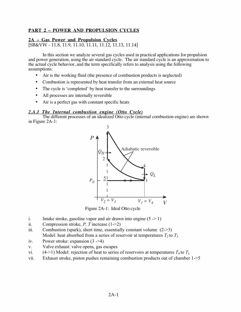
2.A.1 The Internal combustion engine (Otto Cycle)The different processes of an idealized Otto cycle (internal combustion engine) are shown
in Figure 2A-1:
P
V
P0
V2 = V3 V1 = V4
5
2
3
4
1
QH
QL
Adiabatic reversible
Figure 2A-1: Ideal Otto cycle
i. Intake stroke, gasoline vapor and air drawn into engine (5 -> 1)ii. Compression stroke, P, T increase (1->2)iii. Combustion (spark), short time, essentially constant volume (2->3)
Model: heat absorbed from a series of reservoir at temperatures T2 to T3
iv. Power stroke: expansion (3 ->4)v. Valve exhaust: valve opens, gas escapesvi. (4->1) Model: rejection of heat to series of reservoirs at temperatures T4 to T1
vii. Exhaust stroke, piston pushes remaining combustion products out of chamber 1->5
2A-2
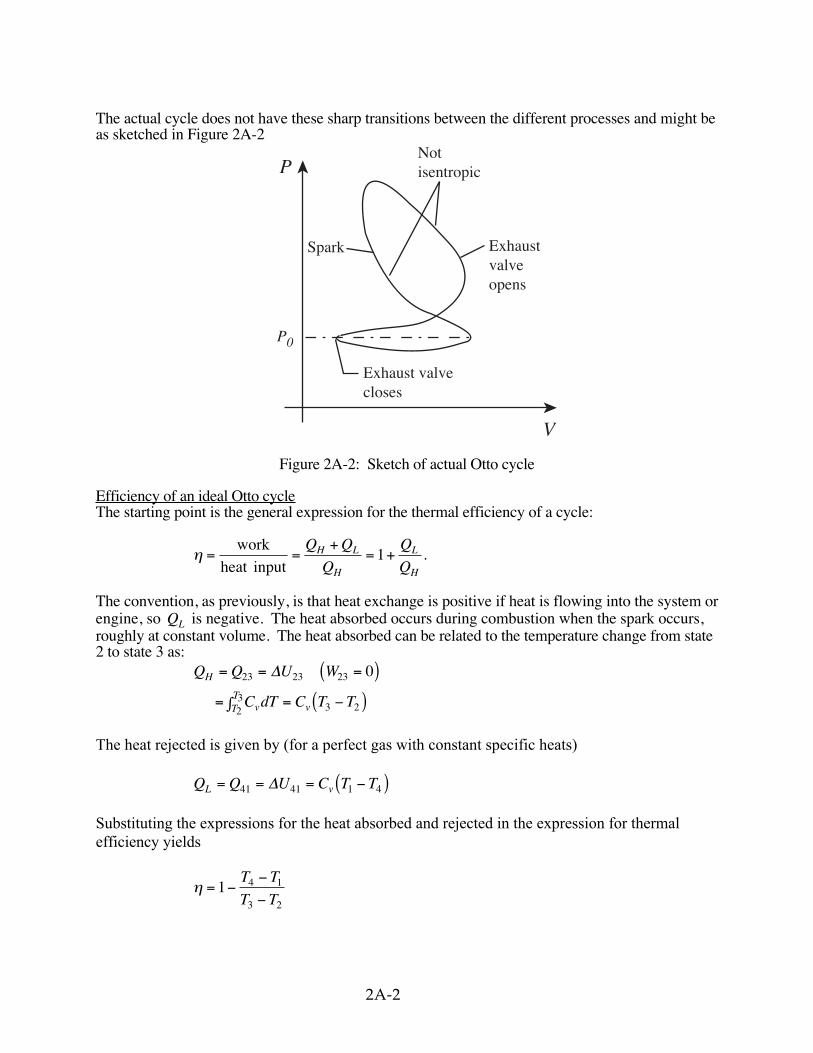
The actual cycle does not have these sharp transitions between the different processes and might beas sketched in Figure 2A-2
Spark Exhaustvalveopens
Notisentropic
Exhaust valvecloses
P
P0
V
Figure 2A-2: Sketch of actual Otto cycle
Efficiency of an ideal Otto cycleThe starting point is the general expression for the thermal efficiency of a cycle:
η = =+
= +work
heat input
Q Q
Q
Q
QH L
H
L
H
1 .
The convention, as previously, is that heat exchange is positive if heat is flowing into the system orengine, so QL is negative. The heat absorbed occurs during combustion when the spark occurs,roughly at constant volume. The heat absorbed can be related to the temperature change from state2 to state 3 as:
Q Q U W
C dT C T T
H
vTT
v
= = =( )= ∫ = −( )
23 23 23
23
3 2
0∆
The heat rejected is given by (for a perfect gas with constant specific heats)
Q Q U C T TL v= = = −( )41 41 1 4∆
Substituting the expressions for the heat absorbed and rejected in the expression for thermalefficiency yields
η = −−
−1 4 1
3 2
T T
T T
2A-3
We can simplify the above expression using the fact that the processes from 1 to 2 and from 3 to4 are isentropic:
T V T V T V T V
T T V T T V
T T
T T
V
V
4 11
3 21
1 11
2 21
4 1 11
3 2 21
4 1
3 2
2
1
1
γ γ γ γ
γ γ
γ
− − − −
− −
−
= =
−( ) = −( )
−
−=
,
The quantity V
Vr1
2
= is called the compression ratio. In terms of compression ratio, the
efficiency of an ideal Otto cycle is:
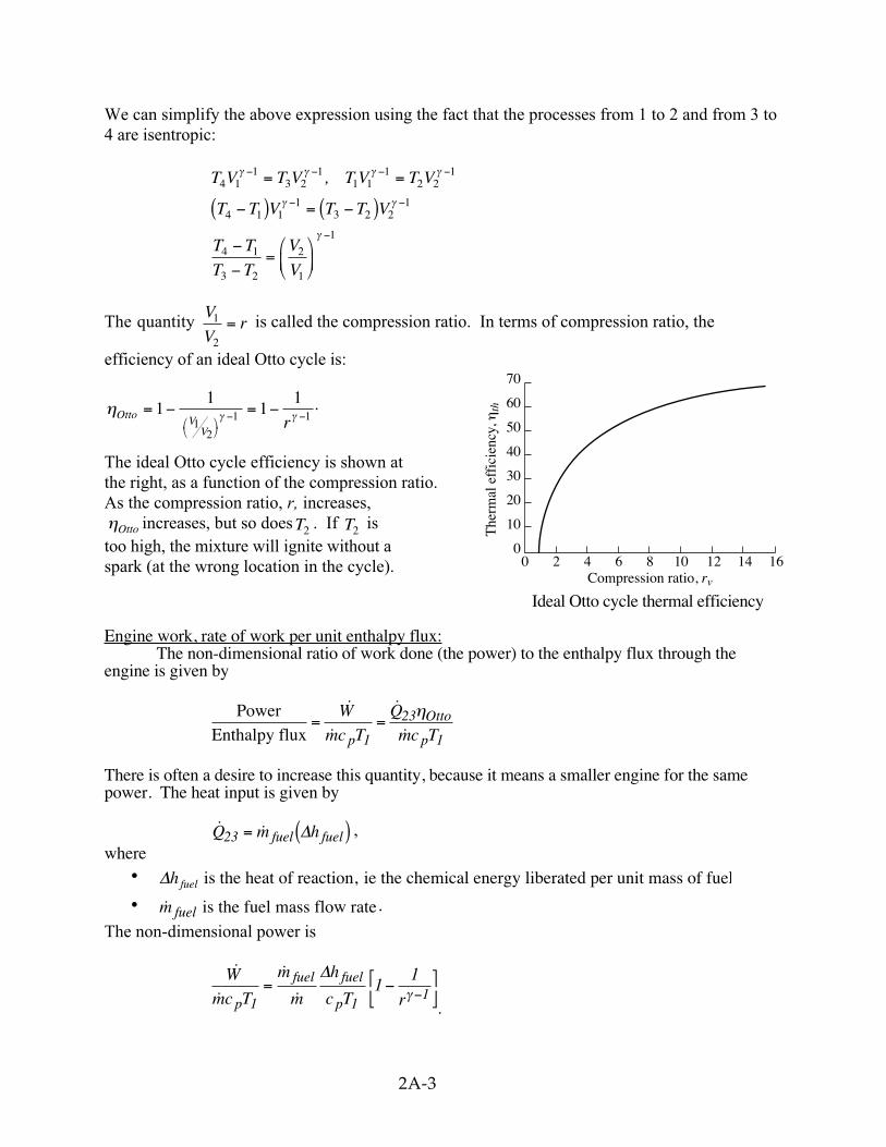
η γ γOtto VV
r= − = −
− −11
11
12
1 1.
The ideal Otto cycle efficiency is shown atthe right, as a function of the compression ratio.As the compression ratio, r, increases,ηOtto increases, but so does T2 . If T2 istoo high, the mixture will ignite without aspark (at the wrong location in the cycle).
Ideal Otto cycle thermal efficiency
Engine work, rate of work per unit enthalpy flux:The non-dimensional ratio of work done (the power) to the enthalpy flux through the
engine is given by
PowerEnthalpy flux
= =˙
˙
˙
˙W
mc T
Q
mc Tp
Otto
p1
23
1
η
There is often a desire to increase this quantity, because it means a smaller engine for the samepower. The heat input is given by
˙ ˙Q m hfuel fuel23 = ( )∆ ,where
• ∆hfuel is the heat of reaction, ie the chemical energy liberated per unit mass of fuel
• m fuel is the fuel mass flow rate .
The non-dimensional power is
˙
˙
˙
˙W
mc T
m
m
h
c T rp
fuel fuel
p1 11
11
= −
−
∆γ
.
00
10
20
30
40
50
60
70
2 4 6 8Compression ratio, rv
The
rmal
eff
icie
ncy,
ηth
10 12 14 16
2A-4
The quantities in this equation, evaluated at stoichiometric conditions are:˙
˙,
m
m
1
15
h
c T
4 10
10 288fuel fuel
p 1
7
3≈ ≈
×
×
∆
so,˙
˙W
mc T rp 11
9 11
≈ −
−γ .
Muddy points
How is ∆ h fuel calculated? (MP 2A.1)What are "stoichiometric conditions"? (MP 2A.2)
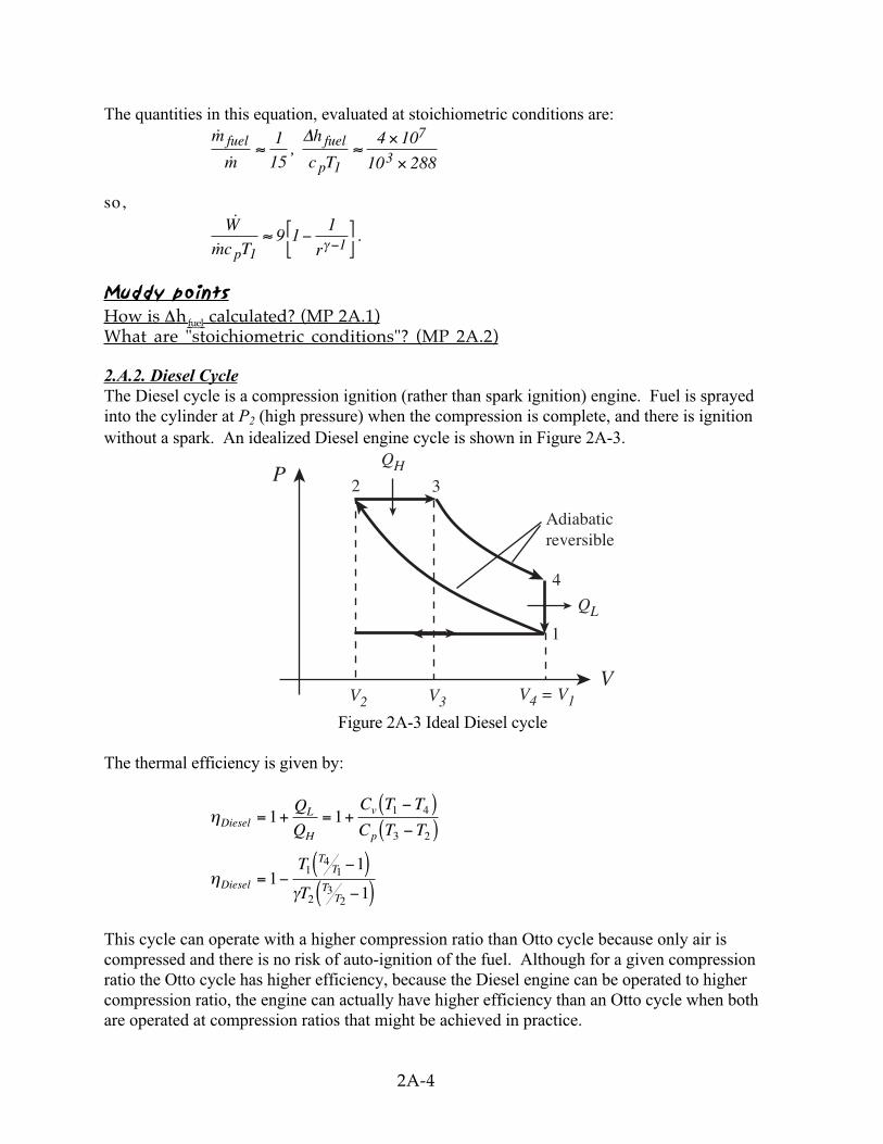
2.A.2. Diesel CycleThe Diesel cycle is a compression ignition (rather than spark ignition) engine. Fuel is sprayedinto the cylinder at P2 (high pressure) when the compression is complete, and there is ignitionwithout a spark. An idealized Diesel engine cycle is shown in Figure 2A-3.
QHP
V2
VV3 V4 = V1
QL
Adiabaticreversible
2 3
4
1
Figure 2A-3 Ideal Diesel cycle
The thermal efficiency is given by:
η
ηγ
DieselL
H
v
p
Diesel
TT
TT
Q
Q
C T T
C T T
T
T
= + = +−( )−( )
= −−( )−( )
1 1
11
1
1 4
3 2
14
1
23
2
This cycle can operate with a higher compression ratio than Otto cycle because only air iscompressed and there is no risk of auto-ignition of the fuel. Although for a given compressionratio the Otto cycle has higher efficiency, because the Diesel engine can be operated to highercompression ratio, the engine can actually have higher efficiency than an Otto cycle when bothare operated at compression ratios that might be achieved in practice.
2A-5
Muddy pointsWhen and where do we use c v and c p ? Some definitions use dU=c v dT. Is it everdU=c p dT? (MP 2A.3)Explanation of the above comparison between Diesel and Otto. (MP 2A.4)
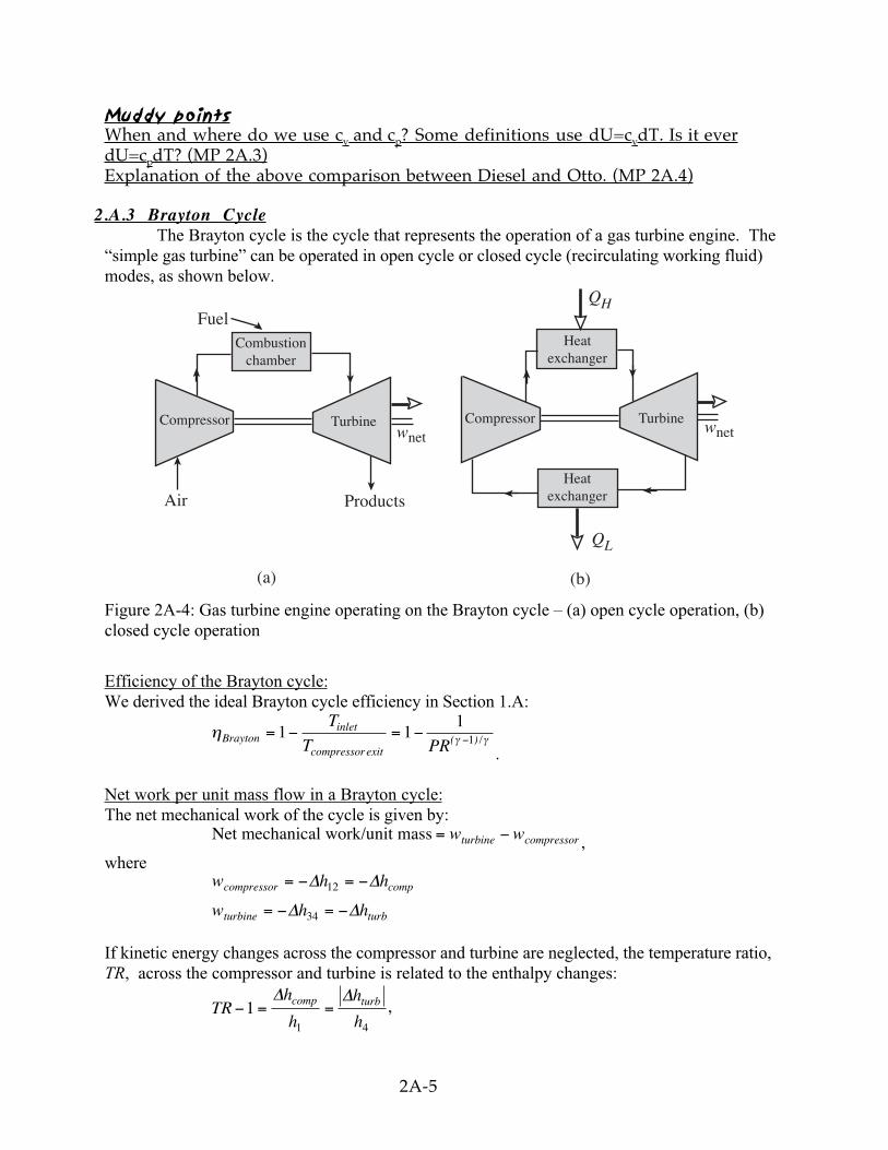
2.A.3 Brayton CycleThe Brayton cycle is the cycle that represents the operation of a gas turbine engine. The
“simple gas turbine” can be operated in open cycle or closed cycle (recirculating working fluid)modes, as shown below.
FuelQH
wnetwnet
ProductsAir
QL
Combustionchamber
Compressor Turbine
Heatexchanger
Heatexchanger
Compressor Turbine
(a) (b)
Figure 2A-4: Gas turbine engine operating on the Brayton cycle – (a) open cycle operation, (b)closed cycle operation
Efficiency of the Brayton cycle:We derived the ideal Brayton cycle efficiency in Section 1.A:
η γ γBraytoninlet
compressorexit
T
T PR= − = − −1 1
11( ) /
.
Net work per unit mass flow in a Brayton cycle:The net mechanical work of the cycle is given by:
Net mechanical work/unit mass = −w wturbine compressor ,where
w h h
w h h
compressor comp
turbine turb
= − = −
= − = −
∆ ∆
∆ ∆12
34
If kinetic energy changes across the compressor and turbine are neglected, the temperature ratio,TR, across the compressor and turbine is related to the enthalpy changes:
TRh
h
h
hcomp turb− = =11 4
∆ ∆,
2A-6
∆ ∆h hh
hturb comp= − 4
1
The net work is thus
net work = −
∆h
h
hcomp4
1
1
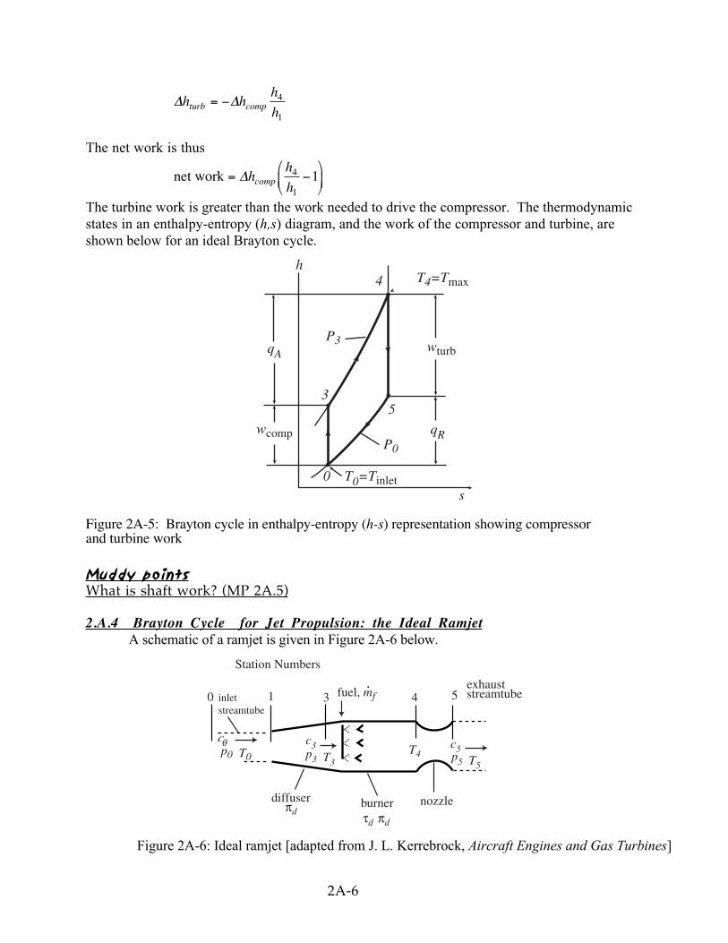
The turbine work is greater than the work needed to drive the compressor. The thermodynamicstates in an enthalpy-entropy (h,s) diagram, and the work of the compressor and turbine, areshown below for an ideal Brayton cycle.
h4 T4=Tmax
wturb
qR
s0 T0=Tinlet
5
P0
wcomp
qA
P3
3
Figure 2A-5: Brayton cycle in enthalpy-entropy (h-s) representation showing compressorand turbine work
Muddy pointsWhat is shaft work? (MP 2A.5)
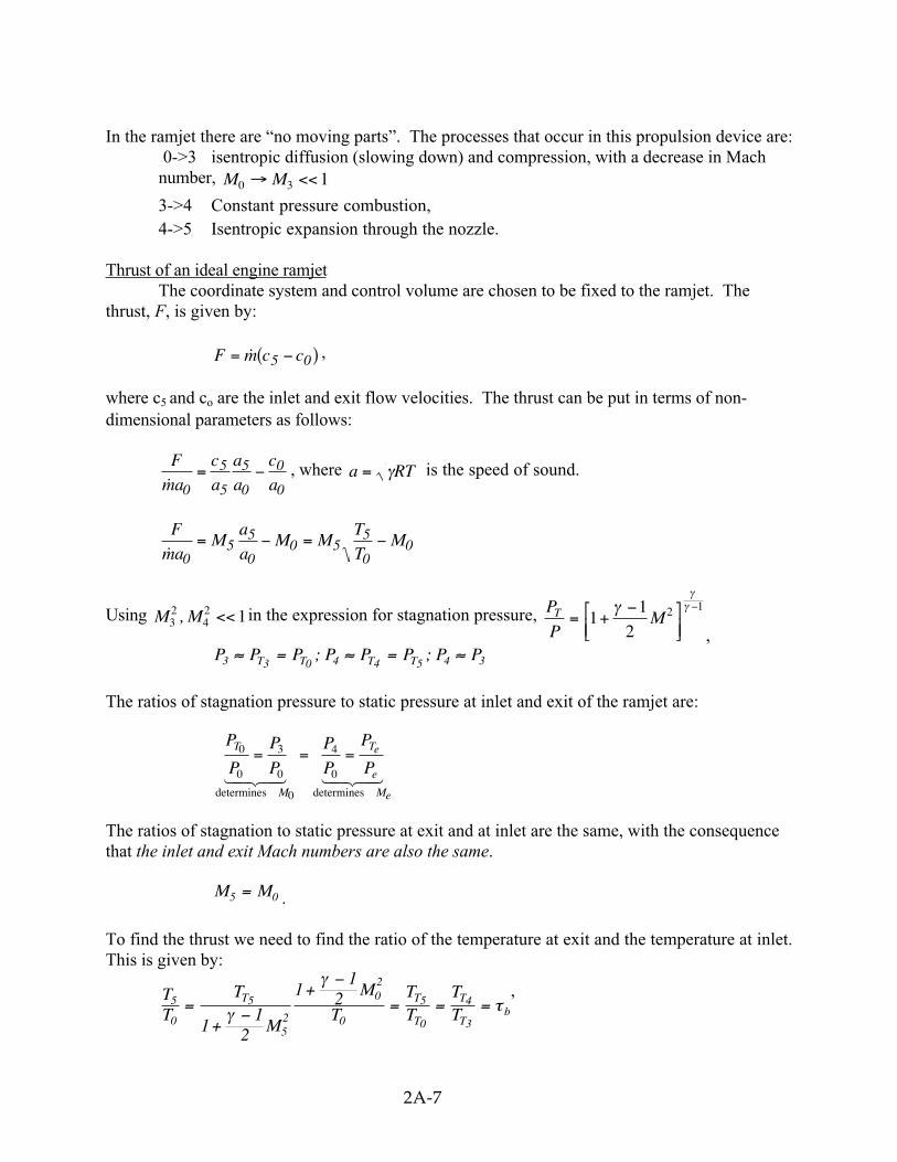
2.A.4 Brayton Cycle for Jet Propulsion: the Ideal RamjetA schematic of a ramjet is given in Figure 2A-6 below.
0 1 3 4 5inletstreamtube
cθp0 T0
c3p3 T3
diffuserπd
burnerτd πd
nozzle
Station Numbers
fuel, mf. exhaust
streamtube
T4c5p5 T5
Figure 2A-6: Ideal ramjet [adapted from J. L. Kerrebrock, Aircraft Engines and Gas Turbines]
2A-7
In the ramjet there are “no moving parts”. The processes that occur in this propulsion device are: 0->3 isentropic diffusion (slowing down) and compression, with a decrease in Machnumber, M M0 3 1→ <<
3->4 Constant pressure combustion, 4->5 Isentropic expansion through the nozzle.
Thrust of an ideal engine ramjetThe coordinate system and control volume are chosen to be fixed to the ramjet. The
thrust, F, is given by:
F c c= −( )m 5 0 ,
where c5 and co are the inlet and exit flow velocities. The thrust can be put in terms of non-dimensional parameters as follows:
F
a
c
a
a
a
c
am 0
5
5
5
0
0
0= − , where a RT= γ is the speed of sound.
F
aM
a
aM M
T
TM
m 05
5
00 5
5
00= − = −
Using M M32
42 1, << in the expression for stagnation pressure, P
PMT = +
−
−1
1
22 1γ
γγ
,P P P P P P P PT T T T3 3 0 4 4 5 4 3≈ = ≈ = ≈; ;
The ratios of stagnation pressure to static pressure at inlet and exit of the ramjet are:
P
P
P
P
P
P
P
PT
M
Te
e
Me
0
0
3
0
0
4
0
= = =
determines determines1 24 34 1 24 34
The ratios of stagnation to static pressure at exit and at inlet are the same, with the consequencethat the inlet and exit Mach numbers are also the same.
M M5 0= .
To find the thrust we need to find the ratio of the temperature at exit and the temperature at inlet.This is given by:
TT
T
M
M
TTT
TT
T T
T
T
Tb
5
0
5
52
02
0
5
0
4
311
2
11
2=+
−+
−
= = =γ
γ
τ,
2A-8
where τ b is the stagnation temperature ratio across the combustor (burner). The thrust is thus:
F
aM bm 0
0 1= −( )τ
Cycle efficiency in terms of aerodynamic parameters:
ηBraytoncompressor exit T
T
T
T
T
T
T= − = − = −1 1 10 0
3
0
0
, and T
T MT
0
0 02
1
11
2
=+
−γ, so:
η
γ
γBrayton
M
M=
−
+−
1
2
11
2
02
02
: Ramjet thermodynamic cycle efficiency in terms of flight
Mach number, M0 .
For propulsion engines, the figures of merit includes more than thrust and ηBrayton .
The specific impulse, Isp measures how effectively fuel is used:
IF
g
F
f gspf
= =˙ ˙m m
; Specific Impulse,
where ˙ ˙m mf f= is the fuel mass flow rate.
To find the fuel-air ratio, f, we employ a control volume around the combustor and carry out anenergy balance. Before doing this, however, it is useful to examine the way in which Isp appearsin expressions for range.
Muddy pointsWhat exactly is the specific impulse, Isp, a measure of? (MP 2A.6)How is Isp found for rockets in space where g ~ 0? (MP 2A.7)Why does industry use TSCP rather than Isp? Is there an advantage to this? (MP2A.8)Why isn't mechanical efficiency an issue with ramjets? (MP 2A.9)How is thrust created in a ramjet? (MP 2A.10)Why don't we like the numbers 1 and 2 for the stations? Why do we go 0-3? (MP2A.11)For the Brayton cycle efficiency, why does T 3 =T t0 ? (MP 2A.12)
2.A.5 The Breguet Range Equation[See Waitz Unified Propulsion Notes, No. IV (see the 16.050 Web site)]
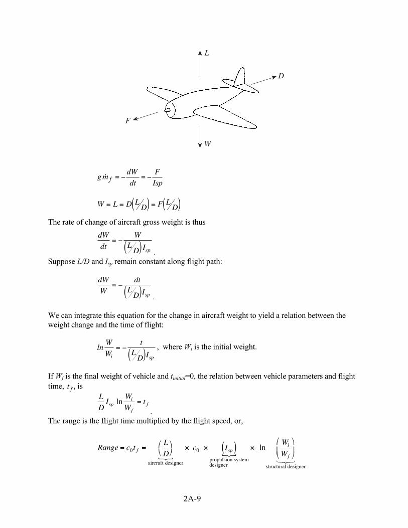
Consider an aircraft in level flight, with weight W. The rate of change of the gross weightof the vehicle is equal to the fuel weight flow:
2A-9
L
D
F
W
gdW
dt
F
Ispfm = − = −
W L D LD F L
D= = ( ) = ( )The rate of change of aircraft gross weight is thus
dW
dt
WL
D Isp
= −( ) .
Suppose L/D and Isp remain constant along flight path:
dW
W
dtL
D Isp
= −( ) .
We can integrate this equation for the change in aircraft weight to yield a relation between theweight change and the time of flight:
lnW
W
tL
D Ii sp
= −( )
, where Wi is the initial weight.
If Wf is the final weight of vehicle and tinitial=0, the relation between vehicle parameters and flighttime, t f , is
L
DI
W
Wtsp
i
ffln =.
The range is the flight time multiplied by the flight speed, or,
Range c tL
Dc I
W
Wf spi
f
= =
× × ( ) ×
0 0
aircraft designerpropulsion systemdesigner structural designer
ln{ {
123
2A-10
The above equation is known as the Breguet range equation. It shows the influence of aircraft,propulsion system, and structural design parameters.
Relation of overall efficiency, I sp , and thermal efficiency
Suppose ∆hfuel is the heating value (‘heat of combustion’) of fuel (i.e., the energy per unitof fuel mass), in J/kg. The rate of energy release is m f fuelh∆ , so
c I cF
g
h
h
Fc
h
h
gspf
fuel
fuel f fuel
fuel0 0
0= =˙ ˙m m
∆
∆ ∆
∆
and Fc
hf fueloverall
0m ∆
=( )
=Thrust power usefulwork
Ideal available energyη (overall propulsion system efficiency)
ηoverallfuel
spg
hc I=
∆ 0
and Range =
∆h
g
L
D
W
Wfuel
overalli
f
η ln
η η η ηoverall thermal propulsive combustion=
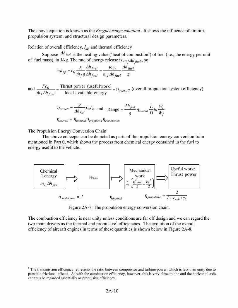
The Propulsion Energy Conversion ChainThe above concepts can be depicted as parts of the propulsion energy conversion train
mentioned in Part 0, which shows the process from chemical energy contained in the fuel toenergy useful to the vehicle.
Figure 2A-7: The propulsion energy conversion chain.
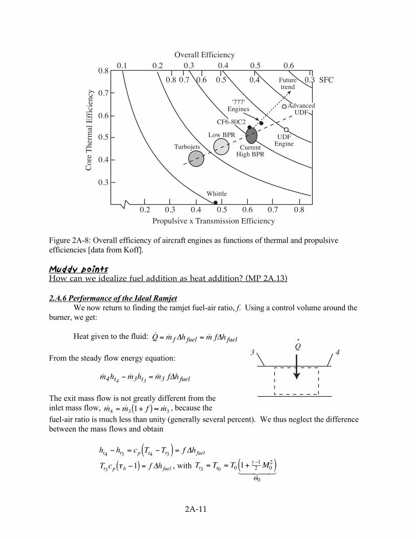
The combustion efficiency is near unity unless conditions are far off design and we can regard thetwo main drivers as the thermal and propulsive1 efficiencies. The evolution of the overallefficiency of aircraft engines in terms of these quantities is shown below in Figure 2A-8.
1 The transmission efficiency represents the ratio between compressor and turbine power, which is less than unity due toparasitic frictional effects. As with the combustion efficiency, however, this is very close to one and the horizontal axiscan thus be regarded essentially as propulsive efficiency.
Chemical1 energy
m hf fuel
⋅∆
Heat
Mechanicalwork
Useful work:Thrust power
ηcombustion 1≅ ηthermalηpropulsive
exitc c= +2
1 0/
mc cexit•
−2
02
2 2
2A-11
0.1 0.2
0.2
0.3
0.3
0.3
0.4
0.4
0.4
0.5
0.5
0.5
0.6
0.6
0.6
0.8
0.8
0.7
0.7
0.6 0.5 0.4 0.30.8
0.7
SFCFuturetrend
AdvancedUDF
'777'Engines
CF6-80C2
Low BPR
Turbojets CurrentHigh BPR
UDFEngine
Cor
e T
herm
al E
ffic
ienc
y
Propulsive x Transmission Efficiency
Whittle
Overall Efficiency
Figure 2A-8: Overall efficiency of aircraft engines as functions of thermal and propulsiveefficiencies [data from Koff].
Muddy pointsHow can we idealize fuel addition as heat addition? (MP 2A.13)
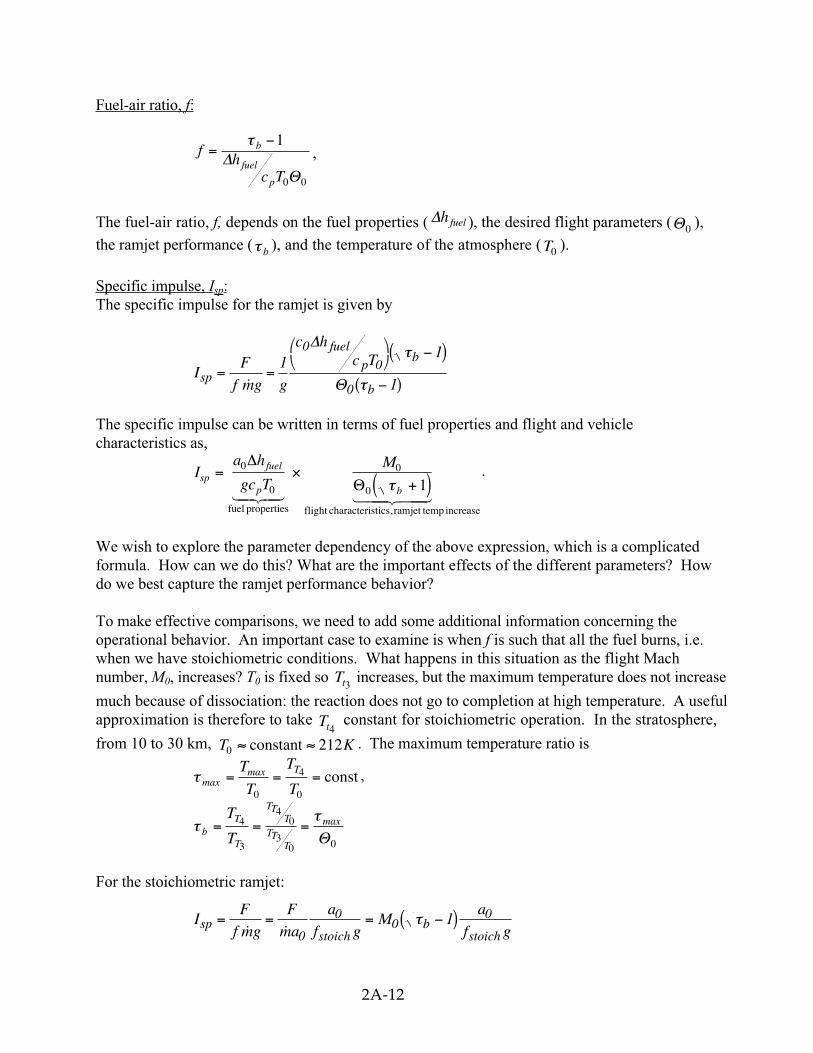
2.A.6 Performance of the Ideal RamjetWe now return to finding the ramjet fuel-air ratio, f. Using a control volume around the
burner, we get:
Heat given to the fluid: ˙ ˙ ˙Q h f hf fuel fuel= =m m∆ ∆
From the steady flow energy equation:
˙ ˙ ˙m m m4 3 34 3h h f ht t fuel− = ∆
The exit mass flow is not greatly different from theinlet mass flow, ˙ ˙ ˙m m f m4 3 31= +( ) ≈ , because the
fuel-air ratio is much less than unity (generally several percent). We thus neglect the differencebetween the mass flows and obtain
h h c T T f ht t p t t fuel4 3 4 3− = −( ) = ∆
T c f ht p b fuel31τ −( ) = ∆ , with T T T Mt t3 0 0
12 0
2
0
1= = +( )−γ
Θ1 24 34
Q3 4
.
2A-12
Fuel-air ratio, f:
fh
c T
b
fuel
p
=−τ 1
0 0
∆Θ
,
The fuel-air ratio, f, depends on the fuel properties ( ∆hfuel ), the desired flight parameters (Θ0 ),
the ramjet performance (τ b ), and the temperature of the atmosphere ( T0 ).
Specific impulse, I sp :The specific impulse for the ramjet is given by
IF
f g g
c hc T
sp
fuel
pb
b= =
−( )
−( )m
11
1
0
0
0
∆
Θ
τ
τ
The specific impulse can be written in terms of fuel properties and flight and vehiclecharacteristics as,
Ia h
gc T
Msp
fuel
p b
= ×+( )
0
0
0
0 1
∆
Θfuel properties flight characteristics, ramjet temp increase124 34 1 244 344
τ.
We wish to explore the parameter dependency of the above expression, which is a complicatedformula. How can we do this? What are the important effects of the different parameters? Howdo we best capture the ramjet performance behavior?
To make effective comparisons, we need to add some additional information concerning theoperational behavior. An important case to examine is when f is such that all the fuel burns, i.e.when we have stoichiometric conditions. What happens in this situation as the flight Machnumber, M0, increases? T0 is fixed so Tt3
increases, but the maximum temperature does not increase
much because of dissociation: the reaction does not go to completion at high temperature. A usefulapproximation is therefore to take Tt4
constant for stoichiometric operation. In the stratosphere,
from 10 to 30 km, T K0 212≈ ≈constant . The maximum temperature ratio is
τ maxmax= = =
T
T
T
TT
0
4
0
const ,
ττ
bT
T
TTT
TTT
T
T= = =4
3
40
30 0
max
Θ
For the stoichiometric ramjet:
IF
f g
F
a
a
f gM
a
f gspstoich
bstoich
= = = −( )˙ ˙m m 0
00
01τ
2A-13
Using the expression forτ b , the specific impulse is
I Ma
f gspstoich
= −
0
0
01τ max
Θ
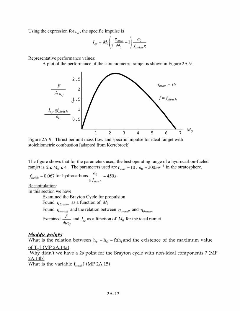
Representative performance values:A plot of the performance of the stoichiometric ramjet is shown in Figure 2A-9.
1 2 3 4 5 6 7
0.5
1
1.5
2
2.5F
m a
I g fa
f = f0
stoic
0
stoic
q = 10b.F
m a0.
Isp gfstoicha0
M0
τmax = 10
f = fstoich
Figure 2A-9: Thrust per unit mass flow and specific impulse for ideal ramjet withstoichiometric combustion [adapted from Kerrebrock]
The figure shows that for the parameters used, the best operating range of a hydrocarbon-fueledramjet is 2 40≤ ≤M . The parameters used areτ max = 10 , a ms0
1300≈ − in the stratosphere,
fstoich = 0 067. for hydrocarbonsa
g fs
stoich
0 450≈ .
Recapitulation:In this section we have:
Examined the Brayton Cycle for propulsionFound ηBrayton as a function of M0
Found ηoverall and the relation between ηoverall and ηBrayton
Examined F
am 0 and Isp as a function of M0 for the ideal ramjet.
Muddy pointsWhat is the relation between h h f ht4 t3 f− = ∆ and the existence of the maximum value
of T t4 ? (MP 2A.14a) Why didn’t we have a 2s point for the Brayton cycle with non-ideal components ? (MP2A.14b)What is the variable f stoich ? (MP 2A.15)
2A-14
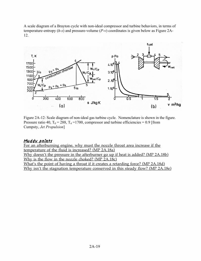
2.A.7 Effect of Departures from Ideal Behavior - Real Cycle behavior[See also charts 69-82 in 16.050: Gas Turbine Engine Cycles]
What are the sources of non-ideal performance and departures from reversibility?- Losses (entropy production) in the compressor and the turbine- Stagnation pressure decrease in the combustor- Heat transfer
We take into account here only irreversibility in the compressor and in the turbine. Because ofthese irreversibilities, we need more work, ∆hcomp (the changes in kinetic energy from inlet to exit
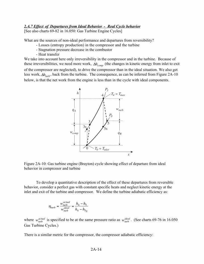
of the compressor are neglected), to drive the compressor than in the ideal situation. We also getless work, ∆hturb , back from the turbine. The consequence, as can be inferred from Figure 2A-10
below, is that the net work from the engine is less than in the cycle with ideal components.
h4
5
5s
3
0
3s
s
qR
qAwturb
T4 = Tmax
T0 = Tinlet
P3
P0
wcomp
Figure 2A-10: Gas turbine engine (Brayton) cycle showing effect of departure from idealbehavior in compressor and turbine
To develop a quantitative description of the effect of these departures from reversiblebehavior, consider a perfect gas with constant specific heats and neglect kinetic energy at theinlet and exit of the turbine and compressor. We define the turbine adiabatic efficiency as:
ηturbturbactual
turbideal
S
w
w
h h
h h= =
−
−4 5
4 5
where wturbactual is specified to be at the same pressure ratio as wturb
ideal . (See charts 69-76 in 16.050
Gas Turbine Cycles.)
There is a similar metric for the compressor, the compressor adiabatic efficiency:
2A-15
ηcompcompideal
compactual
Sw
w
h h
h h= =
−
−3 0
3 0
again for the same pressure ratio. Note that the ratio is the actual work delivered divided by theideal work for the turbine, whereas the ratio is the ideal work needed divided by the actual workrequired for the compressor. These are not thermal efficiencies, but rather measures of thedegree to which the compression and expansion approach the ideal processes.
We now wish to find the net work done in the cycle and the efficiency. The net work is giveneither by the difference between the heat received and rejected or the work of the compressorand turbine, where the convention is that heat received is positive and heat rejected is negativeand work done is positive and work absorbed is negative.
Net work =H
heat in heat out
turb comp
q q h h h h
w w h h h h
L{ {+ = −( ) − −( )
+ = −( ) − −( )
4 3 5 0
4 5 3 0
The thermal efficiency is:
ηthermal =Net work
Heat input
We need to calculate T3 , T5
From the definition ofηcomp , T TT T
TS
c
T ST
c3 0
3 00
30
1− =
−( )=
−( )η η
With T ST
comp
comp3
0
1 1
( ) =
=
− −
isentropic temperature ratio =P
Pexit
inlet
γγ
γγΠ
T T T
comp
comp3 0
1
0
1
=
−
+
−
Πγγ
η
Similarly, by the definition of ηturbext
inlet
P
P
=actual work received
ideal work for same
, we can find T5 :
T T T T TT
TTturb S turb
Sturb Turb4 5 4 5 4
5
44
1
1 1− = −( ) = −
= −
−
η η ηγγΠ
T T Tturb turb5 4 4
1
1= − −
−
ηγγΠ
2A-16
The thermal efficiency can now be found:
ηthermalL
H
Q
Q
T T
T T= + = −
−
−1 1 5 0
4 3
with ΠΠ
Πct
= =1 , and τ
γγ
S =
−
Π1
the isentropic cycle temperature ratio,
η
ητ
ητ
thermal
turbS
compS
T T
T T
= −
− −
−
− −( ) +
1
1 11
11 1
4 0
4 0
or,
ητ
η η τ
η τthermal
Scomp turb S
c S
T
T
T
T
=
−
−
+ −
−
11
1 1
4
0
4
0
There are several non-dimensional parameters that appear in this expression for thermalefficiency. We list these just below and show their effects in subsequent figures:
Parameters reflecting design choices
τγγ
S =
−
Π1
: cycle pressure ratioT
T4
0
: maximum turbine inlet temperature
Parameters reflecting the ability to design and execute efficient componentsηcomp : compressor efficiency
ηturb : turbine efficiency
In addition to efficiency, net rate of work is a quantity we need to examine,˙ ˙ ˙W W Wnet turbine compressor= −
Putting this in a non-dimensional form:˙
˙W
m
work to drive compressor work extracted from flow by turbine
net
p compS turb
Sc T
T
T0
4
0
11 1
1= − −( ) + −
ητ η
τ1 244 344 1 244 344
˙
˙W
c T
TTnet
pS
T
S compm 0
401
1= −( ) −
τη
τ η
2A-17
Trends in net power and efficiency are shown in Figure 2A-11 for parameters typical ofadvanced civil engines. Some points to note in the figure:• For anyη ηcomp turb, ≠ 1 , the optimum pressure ratio ( Π ) for maximum ηth is not the
highest that can be achieved, as it is for the ideal Brayton cycle. The ideal analysis is tooidealized in this regard. The highest efficiency also occurs closer to the pressure ratio formaximum power than in the case of an ideal cycle. Choosing this as a design criterion willtherefore not lead to the efficiency penalty inferred from ideal cycle analysis.
• There is a strong sensitivity to the component efficiencies. For example, forη ηturb comp= = 0 85. , the cycle efficiency is roughly two-thirds of the ideal value.
• The maximum power occurs at a value of τ S or pressure ratio ( Π ) less than that for
maxη . (this trend is captured by ideal analysis).
• The maximum power and maximum ηthermal are strongly dependent on the maximum
temperature, TT
4
0.
Muddy points
How can
TT
4
0
be the maximum turbine inlet temperature? (MP 2A.16)
When there are losses in the turbine that shift the expansion in T-s diagram to theright, does this mean there is more work than ideal since the area is greater? (MP2A.17)
2A-18
Figure 2A-11: Non-dimensional power and efficiency for a non-ideal gas turbine engine - (a)Non-dimensional work as a function of cycle pressure ratio for different values of turbine entrytemperature divided by compressor entry temperature, (b) Overall cycle efficiency as a functionof pressure ratio for different values of turbine entry temperature divided by compressor entrytemperature, (c) Overall cycle efficiency as a function of cycle pressure ratio for differentcomponent efficiencies. [from Cumpsty, Jet Propulsion]
Muddiest points on part 2A
2A.1 How is ∆hfuel calculated?
For now, we rely on tabulated values. In the lectures accompanying Section 2.C of thenotes, we will see how one can calculate the heat , fuelh∆ , liberated in a given reaction.
2A.2 What are "stoichiometric conditions"?
Stoechiometric conditions are those in which the proportions of fuel and air are such thatthere is not an excess of each one--all the fuel is burned, and all the air (oxidizer) is usedup doing it. See Notes Sections 2.C.
2A.3 When and where do we use cv and cp? Some definitions use dU=cvdT. Is it everdU=cpdT?
The answer is no. The definitions of cp and cv are derived in the notes on page 0-6. cp isthe specific heat at constant pressure and for an ideal gas dh = cp dT always holds.Similarly cv is the specific heat at constant volume and for an ideal gas du = cv dT alwaysholds. A discussion on this is also given in the notes on pages 0-6 and 0-7. If you thinkabout how you would measure the specific heat c = q/(Tfinal – Tinitial) for a certain knownchange of state you could do the following experiments.For a process during which heat ∆q is transferred (reversibly) and the volume staysconstant (e.g. a rigid, closed container filled with a substance, or the heat transfer in anOtto engine during combustion – the piston is near the top-dead-center and the volume isapproximately constant for the heat transfer) the first law is du = dq since v = const.Using the definition du = cv dT we obtain for the specific heat at constant volume
cv = ∆q/ ∆T ,
where both the heat transferred ∆q and the temperature difference ∆T can be measured.
Similarly we can do an experiment involving a process where the pressure is keptconstant during the reversible heat transfer ∆q (e.g. a rigid container filled with asubstance that is closed by a lid with a certain weight, or the heat transfer in a jet enginecombustor where the pressure is approximately constant during heat addition). The firstlaw can be written in terms of enthalpy as dh – vdp = dq, and since p = const we obtaindh = dq. Using the definition dh = cpdT we obtain for the specific heat at constantpressure
cp = ∆q/ ∆T .
2A.4 Explanation of the above comparison between Diesel and Otto.
Basically we can operate the diesel cycle at much higher compression ratio than the Ottocycle because only air is compressed and we don't run into the auto-ignition problem(knocking problem). Because of the higher compression ratios in the diesel engine we gethigher efficiencies.
2A.5 What is shaft work?
I am not sure how best to answer, but it appears that the difficulty people are havingmight be associated with being able to know when one can say that shaft work occurs.There are several features of a process that produces (or absorbs) shaft work. First of allthe view taken of the process is one of control volume, rather than control mass (see thediscussion of control volumes in Section 0 or in IAW). Second, there needs to be a shaftor equivalent device (a moving belt, a row of blades) that can be identified as the workcarrier. Third, the shaft work is work over and above the “flow work” that is done by (orreceived by) the streams that exit and enter the control volume.
2A.6 What exactly is the specific impulse, Isp, a measure of?
The specific impulse is a measure of how well the fuel is used in creating thrust. For arocket engine, the specific impulse is the effective exit velocity divided by theacceleration of gravity, g. In terms of relating the specific impulse to some characteristictime, we can write the definition of Isp as
FgmIsp =& .
From this, one can regard the specific impulse as the time that it would take to flow aquantity of fuel that has a weight equal to the thrust force
2A.7 How is Isp found for rockets in space where g ~ 0?
The impulse I given to a rocket is the thrust force integrated over the burn time.Traditionally, for the case of constant exhaust velocity cex, the specific impulse has beenused Isp = I /(mp g) = cex / g0, where mp is the propellant mass and g0 is the Earth's surfacegravity. Thus Isp is measured in seconds and is a force per weight flow. Often today,however, specific impulse is measured in units meters/second [m/s], recognizing thatforce per mass flow is more logical. The specific impulse is then simply equal to theexhaust velocity Isp = cex.
2A.8 Why does industry use TSCP rather than Isp? Is there an advantage to this?
I am not sure why Thrust*Specific Fuel Consumption was originally used. The gasturbine industry uses TSFC; the rocket propulsion industry uses essentially its inverse,Specific Impulse. Perhaps an advantage is that TSFC is a number of magnitude unity,whereas specific impulse is not.
2A.9 Why isn't mechanical efficiency an issue with ramjets?
As defined, the mechanical efficiency represents bearing friction, and other parasitictorques on the rotating shaft in a gas turbine. The work associated with this needs to beprovided by the turbine, but does not go into driving the compressor. The ramjet has noshaft, and hence does not encounter this.
2A.10 How is thrust created in a ramjet?
You can look at thrust in several ways. One is through the integral form of themomentum equation, which relates thrust to the difference between exit and inletvelocities, multiplied by the mass flow. Another way, however, is to look at the forces onthe ramjet structure, basically the summation of pressure forces on all the surfaces. Iattempted to do this in class using the turbojet with an afterburner. For the ramjet, fromthe same considerations, we would have an exit nozzle that was larger in diameter thanthe inlet so that the structural area on which there is a force in the retarding direction issmaller than the area on which there is a force in the thrust direction.
2A.11 Why don't we like the numbers 1 and 2 for the stations? Why do we go 0-3?
A common convention in the industry is that station 0 is far upstream, station 1 is afterthe shock in the inlet (if there is one), station 2 is at inlet to the compressor (after theinlet/diffuser) and station 3 is after the compressor. In class, when we examined theramjet we considered no changes in stagnation pressure between 0 and 2, so I have used 0as the initial state for the compression process. It would be more precise to differentiatebetween stations 0 and 2, and I will do this where appropriate.
2A.12 For the Brayton cycle efficiency, why does T3=Tt0?
The ramjet is operating as a Brayton cycle where ηb= 1 – Tinlet / T compressor exit. For theramjet discussed in class the inlet temperature is T0 and since there is no compressor (nomoving parts) the only compression we get is from diffusion. We assumed isentropicdiffusion in the diffuser and found for very low Mach numbers that the diffuser exit orcombustor inlet temperature T3 is Tt3. From first law we know that for a steady, adiabaticflow where no work is done the stagnation enthalpy stays constant. Assuming perfect gaswe thus get Tt0 = Tt3 = T3. So we can write for the ramjet thermal efficiency
ηb= 1 – T0 / Tt0 .
2A.13 How can we idealize fuel addition as heat addition?
The validity of an approximation rests on what the answer is going to be used for. Weare seeking basically only one item concerning combustor exit conditions, namely theexit temperature or the exit enthalpy. The final state is independent of how we add theheat, and depends only on whether we add the heat. If it is done from an electrical heateror from combustion, and if we neglect the change in the constitution of the gas due to the
combustion products (most of the gas is nitrogen) the enthalpy rise is the same no matterhow the temperature rise is achieved.
2A.14a What is the relation between h h f ht4 t3 f− = ∆ and the existence of the maximum
value of Tt4?
The two are very different physical statements. The first is the SFEE (steady flow energyequation) plus the approximation that inlet and exit mass flows to the control volume arethe same. The heat received within the volume is represented by the quantity f h f∆ ,
where ∆hf is the heat liberated per kilogram of fuel. The second statement is a
representation of the fact that the degree of completion of the reaction in the combustordepends on temperature, so that even though the inlet temperature increases strongly asthe Mach number increases, the combustor exit temperature does not change greatly.This is an attempt to represent a complex physical process (or set of processes) in anapproximate manner, not a law of nature.
2A.14b Why didn’t we have a 2s point for the Brayton cycle with non-ideal components?
If we didn’t, we should have, or I should at least have marked the point at which thecompressor exit would be if the compression process was isentropic.
2A.15 What is the variable fstoich?
fstoich is the fuel-to-air ratio for stoichiometric combustion, or in other words the fuel-to-air ratio for a chemically correct combustion process during which all fuel is burnt.
2A.16 How can TT
4
0
be the maximum turbine inlet temperature?
I agree that the T4/T0 is a temperature ratio. If we assume constant ambient temperaturethen this ratio reflects the maximum cycle temperature. The main point was to emphasizethat the higher your turbine inlet temperature the higher your power and efficiency levels.
2A.17 When there are losses in the turbine that shift the expansion in T-s diagram tothe right, does this mean there is more work than ideal since the area isgreater?
We have to be careful when looking at the area enclosed by a cycle or underneath a pathin the T-s diagram. Only for a reversible cycle, the area enclosed is the work done by thecycle (see notes page 1C-5). Looking at the Brayton cycle with losses in compressor andturbine the net work is the difference between the heat absorbed and the heat rejected(from 1st law). The heat absorbed can be found by integrating TdS = dQ along the heataddition process. The heat rejected during the cycle with losses in compressor and turbineis larger than in the ideal cycle (look at the area underneath the path where heat isrejected, this area is larger than when there are no losses dsirrev = 0 – see also muddy point
1C.1). So we get less net work if irreversibilities are present. It is sometimes easier tolook at work and heat (especially shaft work for turbines and compressors) in the h-sdiagram because the enthalpy difference between two states directly reflects the shaftwork (remember, enthalpy includes the flow work!) and / or heat transfer.
2A.18a For an afterburning engine, why must the nozzle throat area increase if thetemperature of the fluid is increased?
The Mach number of the flow is unity at the throat with and without the afterburnerlit. The ratio of static pressure to stagnation pressure at the throat is thus the samewith and without the afterburner lit. The ratio of static temperature to stagnationtemperature at the throat is thus the same with and without the afterburner lit.
T
TM
P
PMt t= +
−= +
−
−( )1
1
21
1
22 2
1γ γ γ γ
; /
The flow through the throat is
m cA aAP
RTRTAthroat throat throat= = =ρ ρ γ .
The flow through the throat thus scales as
˙
˙/
/
/
/
m
m
P
TA
P
TA
A B
noA B
throatA B
throatnoA B
=
From what we have said, however, the pressure at the throat is the same in both cases.Also, we wish to have the mass flow the same in both cases in order to have theengine operate at near design conditions. Putting these all together, plus use of theidea that the ratio of stagnation to static temperature at the throat is the same for bothcases gives the relation
A
A
T
TthroatA B
throatnoA B
tA B
tnoA B
/
/
/
/
=
The necessary area to pass the flow is proportional to the square root of the stagnationtemperature.
If too much fuel is put into the afterburner, the increase in area cannot be met and theflow will decrease. This can stall the engine, a serious consequence for a singleengine fighter.
2A.18b Why doesn’t the pressure in the afterburner go up if heat is added?
From discussions after lecture, the main point here seems to be that the process ofheat addition in the afterburner, or the combustor, is not the same as heat addition to agas in a box. In that case the density (mass/volume) would be constant and, fromP RT= ρ , increasing the temperature would increase the pressure. In a combustor,the geometry is such that the pressure is approximately constant; this happens because
the fluid has the freedom to expand so the density decreases. From the equationP RT= ρ if the temperature goes up, the density must go down.
2A.18c Why is the flow in the nozzle choked?
As seen in Unified, choking occurs when the stagnation to static pressureratio P Pt /( )gets to a certain value, 1.89 for gas with γ of 1.4. Almost all jet aircraft
operate at flight conditions such that this is achieved. If you are not comfortable withthe way in which the concepts of choking are laid out in the Unified notes, please seeme and I can give some references.
2A.18d What’s the point of having a throat if it creates a retarding force?
As shown in Unified, to accelerate the flow from subsonic to supersonic, i.e., tocreate the high velocities associated with high thrust, one must have a converging-diverging nozzle, and hence a throat.
2A.18e Why isn’t the stagnation temperature conserved in this steady flow?
Heat is added in the afterburner, so the stagnation temperature increases.