Embed Size (px)
Citation preview

National Mapping ProgramTechnical Instructions
Part 1 Template Development andUse
Standards for 1:24,000-ScaleDigital Line Graph andQuadrangle Maps
U.S. Department of the InteriorU.S. Geological SurveyNational Mapping Division

Standards for 1:24,000-Scale Digital Line Graphs and Quadrangle MapsPart 1: Template Development and Use
4/96 1-ii
CONTENTS Page
1. Template Development . . . . . . . . . . . . . . . . . . . . . . . 1-1
1.1 Extraction Specifications . . . . . . . . . . . . . . . . . . . . 1-2
1.1.1 Feature Definitions . . . . . . . . . . . . . . . . . . 1-3
1.1.2 Attributes and Attribute Values . . . . . . . . . . . . 1-5
1.1.3 Delineation . . . . . . . . . . . . . . . . . . . . . . 1-5
1.1.4 Representation Rules . . . . . . . . . . . . . . . . . . 1-6
1.1.5 Capture Conditions . . . . . . . . . . . . . . . . . . . 1-6
1.1.6 Attribute Information . . . . . . . . . . . . . . . . . 1-9
1.1.7 Source Interpretation Guidelines . . . . . . . . . . . 1-10
1.1.7.1 All Sources . . . . . . . . . . . . . . . . . 1-10
1.1.7.2 Graphic . . . . . . . . . . . . . . . . . . . 1-10
1.1.7.3 Revision . . . . . . . . . . . . . . . . . . 1-11
1.2 Product Generation Rules . . . . . . . . . . . . . . . . . . . . 1-13
1.2.1 Inclusion Conditions . . . . . . . . . . . . . . . . . 1-14
1.2.2 Generalization . . . . . . . . . . . . . . . . . . . . 1-14
1.2.3 Symbolization . . . . . . . . . . . . . . . . . . . . 1-15
1.2.4 Conflict Detection and Resolution . . . . . . . . . . 1-17
1.2.4.1 Reading Conflict Detection and Resolution Rules 1-17
1.2.4.2 Spatial Operators . . . . . . . . . . . . . . 1-19
1.2.4.3 Resolution Strategies . . . . . . . . . . . . 1-22
1.2.5 Names and Labels . . . . . . . . . . . . . . . . . . . 1-23
1.3 Discrepancy Report . . . . . . . . . . . . . . . . . . . . . . . 1-24

Standards for 1:24,000-Scale Digital Line Graphs and Quadrangle MapsPart 1: Template Development and Use
4/96 1-iii
APPENDIXES Page
1A Instructions for Using Feature Templates During DLG-3 Revision . 1A-1
1B Part 5 Feature Index to DLG-F Feature . . . . . . . . . . . . . 1B-1
1C Part 6 Feature Index to DLG-F Feature . . . . . . . . . . . . . 1C-1
1D DLG-F to DLG-3 Feature Crosswalk . . . . . . . . . . . . . . . . 1D-1
1E DLG-3 to DLG-F Feature Crosswalk . . . . . . . . . . . . . . . . 1E-1

Standards for 1:24,000-Scale Digital Line Graphs and Quadrangle MapsPart 1: Template Development and Use
4/01 1-iv
LIST OF PAGES
A complete and current copy of Part 1 of Standards for 1:24,000-Scale Digital
Line Graphs and Quadrangle Maps consists of the pages (and most recent creation
or revision dates) listed below.
Page Date
1-ii 4/96
1-iii 4/96
1-iv 4/01
1-1 4/96
1-2 4/96
1-3 4/96
1-4 4/96
1-5 4/96
1-6 4/96
1-7 4/96
1-8 4/96
1-9 4/01
1-10 4/96
1-11 4/96
1-12 4/96
1-13 4/96
1-14 4/96
1-15 4/96
1-16 4/96
1-17 4/96
1-18 4/96
1-19 4/96
1-20 4/96
1-21 4/96
1-22 4/96
1-23 4/96
1-24 4/96
1A-1 4/96
1A-2 4/96
1A-3 4/96
Page Date
1A-4 4/96
1A-5 4/96
1B-1 4/96
1B-2 4/96
1B-3 4/96
1B-4 4/96
1B-5 4/96
1B-6 4/96
1B-7 4/96
1C-1 4/96
1C-2 4/96
1C-3 4/96
1C-4 4/96
1C-5 4/96
1C-6 4/96
1C-7 4/01
1C-8 4/96
1C-9 4/96
1D-1 4/96
1D-2 4/96
1D-3 4/96
1D-4 4/96
1D-5 4/01
1D-6 4/96
1D-7 4/96
1D-8 4/96
1D-9 4/96
1D-10 4/96
1D-11 4/96
1D-12 4/96
Page Date
1D-13 4/96
1D-14 4/96
1D-15 4/96
1D-16 4/96
1D-17 4/96
1E-1 4/01
1E-2 4/96
1E-3 4/96
1E-4 4/01
1E-5 4/96
1E-6 4/96
1E-7 4/96
1E-8 4/96
1E-9 4/96
1E-10 4/96
1E-11 4/96
1E-12 4/01
1E-13 4/96
1E-14 4/96

Standards for 1:24,000-Scale Digital Line Graphs and Quadrangle MapsPart 1: Template Development and Use
4/96 1-1
1. TEMPLATE DEVELOPMENT
The following information describes how to use the feature
templa tes. The sections explain what is included in each part of
the temp late and any global rules that apply throughout the
templates. If a rule applies to all features, it is a global rule.
An example is a rule for how to measure a feature to determine if it
meets capture conditions. The templates contain o nly exceptions to
the global rule or additional information that is unique to the
feature. If nothing appears in the template to change a global
rule, then the rule applies.
Thro ughout the templates, if something being described meets the
definition and capture conditions of a feature, the feature name
appears in all CAPS. Generic descriptions of features appear in
lower case type to indicate they may not meet the definition of the
feature and should not be considered as that feature.
There are three reasons why an entry in the template does not
contain information.
1. There is no applicable information, indicated by N/A.
Examples:
o Attribute/Attribute Value list when a feature has no
attributes
o Attribute Information when a feature has no attributes
o Various specifications in the symbol table that don't
apply
2. There is information not yet developed, indicated by TBD.
Examples:
o Rules for Names and Labels
3. In some cases, information could be developed, but none is
currently available, indicated by a blank.
Examples:
o Generalization
o Conflict Detection and Resolution

Standards for 1:24,000-Scale Digital Line Graphs and Quadrangle MapsPart 1: Template Development and Use
4/96 1-2
1.1 EXTRACTION SPECIFICATIONS
The data extraction specifications in the feature templates contain
all the information required to collect feature data. These
specifications tell what is collected as a certain feature and when
and how the feature is collected. The extraction specifications
include:
1.1.1 Feature Definitions
1.1.2 Attribute and Attribute Values
1.1.3 Delineation
1.1.4 Representation Rules
1.1.5 Capture Conditions
1.1.6 Attribute Information
1.1.7 Source Interpretation Guidelines
The templates are as concise and positive as possible, and each
template is meant to stand alone. Therefore, definitions,
attr ibutes, and attribute values describe what the feature looks
like, not what it DOES NOT look like. Similarly, capture conditions
explain when to capture a feature, not when NOT TO capture the
feature. If this approach had not been used, each template could be
too cumbersome, and too confusing, to be useful.
The capture conditions reflect the NMD policy of cartographic
collection, which restricts data content and position based on
graphic limitations of scale and legibility. Only content that can
be disp layed on the printed map is collected and all offsets in
position necessary to accommodate symbolization are performed at the
time of data collection. This policy, and the feature templates,
will change as user requirements for geographic content and position
become known and as technology and resources are developed to
support the implementation of product generation rules for content
generalization and symbol conflict resolution.

Standards for 1:24,000-Scale Digital Line Graphs and Quadrangle MapsPart 1: Template Development and Use
4/96 1-3
1.1.1 Feature Definitions
Feature definitions are used to decide how to classify a feature.
Attributes, delineation, and capture conditions limit which
occurrences of a feature, from a class of features, the NMD
collects. The main goal in classifying features is to define the
features so that the distinctions between them are clear.
The fe atures and their definitions were developed by studying a
variety of sources including; NMD documentation; the Defense Mapping
Agency's Feature and Attribute Coding System; Geographic Names
Infor mation System feature classes; the Spatial Data Transfer
Standard feature list; publications from other Federal agencies,
including National Ocean Service, Bureau of Land M anagement, Forest
Service, and the Fish and Wildlife Service; and the Canadian
National Topographic Data Base feature list. Atte mpts were made to
coordinate feature definitions with other organizations, however,
feature selection is somewhat different from one agency to another
and even between units within each agency.
The feature definitions provide the distinguishing characteristics
needed to differentiate between features. Although the difference
between STREAM/RIVER and LAKE/POND is obvious, the distinction
between STREAM/RIVER and CANAL/DITCH may not be so obvious. In this
example, a feature that could be either a STREAM/RIVER or a
CANAL/DITCH can be classified by comparing the two definitions.
Although both STREAM/RIVER and CANAL/DITCH are lin ear water bodies,
the definition for CANAL/DITCH specifies that it is artificial and
that it is used to transport water, to drain or irrigate land, to
connect two or more water bodies, or to serve as a waterway for
watercraft. Therefore, CANAL/DITCH is distinguished from
STREAM/RIVER by (1) the fact that it is artificial, and (2) the fact
that it has specific uses. If the feature in question does not meet
these two criteria, it is not a CANAL/DITCH.

Standards for 1:24,000-Scale Digital Line Graphs and Quadrangle MapsPart 1: Template Development and Use
4/96 1-4
Although the feature definitions include those cha racteristics of a
feature that the NMD uses to distinguish among features, the
templ ates do not necessarily specify how to make the distinction.
How one goes about deciding if something is artificial or natural,
or if it is used for some special purpose or not, is beyond the
scope of the templates. Annotation guides can be developed to
support the content of the templates. These guides could contain
graphic examples that illustrate map and real world identification
and delineation of features.
There are some cases where the distinction between features is not
clear, usually because past practices do not lend themselves to the
classification method used to develop the domain of features. There
are also cases where the definition is clear, but, again, because of
past practices in the NMD, there might be some confusion. For
example, the definition of a LAKE/POND states that it is a "body of
standing water," so a dry lake doesn't fit the definition. However,
the NMD symbol books describe dry lakes under lakes and ponds and in
the DLG-3 format they are collected as lakes with a descriptive
attribute of dry. In this case, a rule is developed in Source
Interpretation Guidelines to reinforce the definit ion. The rule in
this exa mple is: "Do not capture dry lakes as LAKE/POND. See
PLAYA."
Standards for 1:24,000-Scale Digital Line Graphs and Quadrangle MapsPart 1: Template Development and Use
4/96 1-5
1.1.2 Attributes and Attribute Values
Attrib utes describe characteristics of features. Many of these
characteristics fall into one of three groups: (1) "Type" describes
the function or purpose of a feature; (2) "Category" describes the
form or nature of a feature; and (3) "Status" describes the state or
existence of the feature or characteristic.
Defin itions for attributes and attribute values are generic. The
definition for the attribute "Elevation" is "The vertical distance
from a given datum." This applies whether elevation is applied to
a LAKE/POND or a STREAM/RIVER or a CONTOUR.
In some cases, more than one value for a given attribute can be
selected. The ability to provide multiple values for an attribute
makes it unnecessary to capture multiple features. For example, if
a mine produces multiple products, only one instance of the feature
mine is captured and the applicable products are a ssigned as values
to the attribute Product. Currently, the templates do not identify
those attributes that can be multi-valued, although the information
is stored in the standards data base.
For most features, there is a discrete list of appropriate attribute
values. However, for a few features, such as RESERVATION, the
number of potential descriptors is quite large and it is not
possible to create an exhaustive list of values. Selecting an
alphanumeric value for the attribute "Text" provides the necessary
flexibility to describe a RESERVATION.
1.1.3 Delineation
Delineation specifications describe what the limits of a feature are
and what to include in the feature that meets capture conditions.
The delineation generally describes real world entities.

Standards for 1:24,000-Scale Digital Line Graphs and Quadrangle MapsPart 1: Template Development and Use
4/96 1-6
1.1.4 Representation Rules
The representation rules are described in two tables. The first
table lists the relationships in which a feature may participate and
the second table lists the feature object types used to represent
the feature.
The re lalationship table presents the relationship name, the
cardinality, and the related feature object. The cardinality
expresses the minimum and maximum number of times one instance of a
feature can be involved in the relationship. However, the current
design of the standards database is flawed and the cardinality
cannot be entered properly, so the cardinality is not populated.
The representation conditions table presents the feature objects
used to represent a feature and the criteria to determine which
feature object is used. The values displayed in the columns for
"AREA", "SHORTEST" and "LONGEST" are sizes based on an areal
measurement, the shortest axis, or the longest axis of the feature.
A feature is represented by a specific feature obj ect when the size
criteria in the appropriate column is met. If a feature can only be
represented by one feature object, then the only value shown will be
">0" in one of the columns. If no values appear in any column, then
special conditions must be present to indicate the appropriate
feature representation. Special conditions may also exist in
conjunction with values in table.
1.1.5 Capture Conditions
The f eature definitions describe what to capture, and the capture
condit ions describe when to capture it. Capture conditions are
generally independent of source. The capture conditions currently
reflect the content of a standard update product. Because primary
mapping has been completed for the entire United States, most
National Mapping Program activity is focused on revision.
Information on data capture that pertains to specific sources or
revision methods is found in the Source Interpretation Guidelines
section.

Standards for 1:24,000-Scale Digital Line Graphs and Quadrangle MapsPart 1: Template Development and Use
4/96 1-7
The templates must contain the criteria necessary to ensure that NMD
products are accurate and consistent in style and content.
Therefore, the capture conditions present the requirements for the
content of NMD products, not just the step-by-step decisions an user
needs to make in deciding whether to capture a particular feature.
An If...Then" format is used for the capture condi tions. The basic
format is as follows:
If FEATURE is CONDITION,Then capture.
When there are multiple capture conditions, each statement stands
alone. If the feature meets one of the conditions, it is captured.
Capture conditions are given in inches at map scale. In general,
features are measured along the longest axis (length) and/or the
shortest axis (width). Square features are measured along either
axis, round features are measured by the diameter, and irregular
features are measured against the axes of the best fitting rectangle
(non oriented). Linear features are measured as the accumulative
measurement along the centerline of the feature for length and the
predominant distance across the feature (measured perpendicular to
the centerline) for width. Any specific or unique requirements for
measurement are addressed separately for each feature.

2O
2O 4O
1O
0.1O
0.1O
2 ft.
2 ft.
Standards for 1:24,000-Scale Digital Line Graphs and Quadrangle MapsPart 1: Template Development and Use
4/96 1-8
For a real measurements, the capture conditions are expressed as X
square inches. Square inches indicate that the value is an areal
value . Thus, 4 square inches indicates an area equivalent in extent
to a square which measures 2" by 2", or to a rectangle which
measures 1" by 4". Two examples of area = 4 square inches are:
Decimal values are handled in the same way; an area described as
0.01 square inches indicates an area equivalent in size to a square
which measures 0.1" by 0.1". An example of area = 0.01 square inches
is:
Do not confuse this terminology with the usage "2 foot square,"
where neither the value nor the unit is areal. For example:
The areal value terminology is used in the templates because it
allows an area to be defined independently of lengths and widths.
If there are minimum length or width requirements, then these values
are included in the capture conditions in addition to the area
value.

Standards for 1:24,000-Scale Digital Line Graphs and Quadrangle MapsPart 1: Template Development and Use
4/01 1-9
1.1.6 Attribute Information
Attribute Information describes how to value the attributes once the
feature is captured. Any required conditions and/or attribute value
combinations are given. All attributes must be valued.
There are three global attribute values that apply to many
attributes. These are "Unspecified", "Not Applicable", and
"Unknown".
o Unspecified is used when the value is not known, but is not
necessary. For example, a spring shown on the map with no
additional label would have the value Unspecified for the
attribute Water Characteristics.
o Not Applicable is used when a particular occurrence of a
feature cannot have a particular attribute value. For
example, if the water level of a STREAM/RIVER is not
controlled for navigation, the value for Elevation = Not
Applicable, because the attribute does not apply and therefore
cannot be valued.
o Unknown is used when a required value is not known. For
example, if the class of a road cannot be determined during
collection or revision, the value would be unknown. Other
sources will be required to determine the appropriate value.

Standards for 1:24,000-Scale Digital Line Graphs and Quadrangle MapsPart 1: Template Development and Use
4/96 1-10
1.1.7 Source Interpretation Guidelines
Source Interpretation Guidelines provide additional information for
inter preting the capture conditions when capturing data using
specific source materials or methods. They also contain any
modif ications to the capture conditions specific to the source or
capture methods.
1.1.7.1 All sources
This information helps interpret the capture conditions regardless
of the source or method used in data capture. Included are such
things as when to capture a coincident feature based on the capture
conditions, when to capture more than one instance of the feature,
and when to capture something as a different feature instead of the
feature in the template. For those features that can occur in more
than one theme, this section provides the guidelines for which theme
should contain a specific feature instance.
1.1.7.2 Graphic
This information helps interpret the capture conditions when the
source is a map. Included are guidelines for interpreting the
symbology for proper classification, delineation, and capture.
When deciding to capture a feature from a graphic source, the
capture conditions still apply. Features that do not meet the
capture conditions are not captured. Generally, this reflects
changing requirements. For example, a number of offshore features
shown on NMD maps prior to 1961 are no longer required and should
not be captured, even though they appear on the graphic.
Some capture conditions cannot be evaluated just by looking at the
map. For example, when a feature is represented with a point symbol
and the capture conditions state a size requirement, it is not
possible to evaluate the true size of the feature from the graphic.
If compliance with the capture conditions cannot be determined, then
the fe ature is collected. Further evaluation will be done at the
time of revision.

Standards for 1:24,000-Scale Digital Line Graphs and Quadrangle MapsPart 1: Template Development and Use
4/96 1-11
In some cases, instructions are given to collect f eatures for which
the symbology has been suppressed on the map. For example,
instructions are given on how to capture PLSS info rmation when PLSS
lines are dropped from the map because they are coincident with a
boundary or a road.
1.1.7.3 Revision
This information helps interpret the capture conditions during
revision. The term "revision" applies to the proc ess by which data
are updated to reflect changes that have occurred since the date of
the existing DLG or, for simultaneous collection and revision, the
Digital Raster Graphic (DRG).
Guidelines in this section are divided by the cate gory of revision.
Headings in this section are: Revision - General, Revision -
Standard, and Revision - Limited. If no guidelines appear in any of
these revision categories, then the guidelines in the remainder of
the feature template apply.
Revision - General
Revision - Standard
Revisions - Limited - The goal for a limited update is that feature
content will be current, but will include only: (1) those feature
types that are photoidentifiable on a monoscopic source,
supplemented with limited ancillary sources, and (2) those feature
types from existing DLG's or DRG's that are not photoidentifiable
but are not particularly prone to change. Some feature types are
not revised at all while other feature types are revised with
limited attribution. Existing data may or may not be revised.
Ancillary sources may be required to revise some d ata. All of this
information is provided in the limited update section.
If no limited update guidelines appear, the feature and all its
attrib utes are revised using guidelines in the remainder of the
template.

Standards for 1:24,000-Scale Digital Line Graphs and Quadrangle MapsPart 1: Template Development and Use
4/96 1-12
If a feature is not revised during a limited update, guidelines
state this and give information on how to handle e xisting DLG data.
The guideline "Do not revise. Delete existing fea tures." means the
feature is not revised and all feature instances are deleted from
the DLG. The guideline "Do not Revise. Retain existing features."
means the feature is not revised and features that already exist in
the DLG are retained except when that feature is replaced by another
instance of a feature type that is revised in a limited update.
If a feature is revised, but only under certain conditions, those
conditions will be stated, as well as how to handle existing DLG
data. For example, in the feature PIPELINE, the guideline states
"Revise aboveground pipelines only. Retain existing features."
There are some cases where only existing DLG data are revised and
only under certain conditions. The guideline "Do not add new
features. Revise existing features (conditions)." applies to these
cases.
Special instructions may also apply to attribution. If attribution
cannot be determined in limited update, that will be noted in this
section. For example, the guideline for BUILDING states that
Building Type = Unspecified for limited update. In addition it
will be noted whether the value applies to existing data or not. In
the case of BUILDING, the guideline states "Existing buildings will
be given Building Type = Unspecified."
If data is being collected from a DRG as part of a simultaneous
collection/revision project, the limited update instructions still
apply. W hen revising data from a DRG, the term "retain" is
interpreted to mean "collect" and the term "delete" is interpreted
to mean "do not collect". So, the guideline "Do not revise. Retain
existing features" means "Do not revise. Collect existing features"
The guideline "Do not revise. Delete existing features" means "Do
not revise. Do not collect existing features."

Standards for 1:24,000-Scale Digital Line Graphs and Quadrangle MapsPart 1: Template Development and Use
4/96 1-13
1.2 PRODUCT GENERATION RULES
The feature definitions, delineation, extraction specifications, and
repres entation rules provide the guidelines for creating a data
base. Upon creation of the data base, an additional set of rules is
needed to provide guidelines for manipulating and processing the
data to generate a particular cartographic product. These product
generation rules are divided into five groups:
1.2.1 Inclusion conditions
1.2.2 Generalization
1.2.3 Symbolization
1.2.4 Conflict detection and resolution
1.2.5 Names and labels
The information in the Product Generation sections is not as
complete as the information in the Data Extraction sections.
Additions and modifications to the rules will occur as research
continues. The Symbolization section is the most complete. The
Conflict Detection and Resolution section and the Names and Labels
section contain rules that have been identified thus far in the
process, but these sections will require additional research.
Inclusion Conditions and Generalization requirements are described
in the template under the heading "Data Extraction or Product
Generation." Depending on the content of the data base, these
activities could take place at different times in the production
process. Current collection policy dictates that the database
contains only the information required to create a map, therefore
the inclusion conditions are equivalent to the capture conditions
and gen eralization is not required. A collection policy that
permits more geographic collection, would mean that the database
contains information other than that required to create a specific
prod uct. Inclusion Conditions and Generalization for specific
products then will be defined.
Standards for 1:24,000-Scale Digital Line Graphs and Quadrangle MapsPart 1: Template Development and Use
4/96 1-14
1.2.1 Inclusion Conditions
Inclusion conditions are used to select feature instances from the
data base to meet the requirements of a particular product. The
policy in data extraction is to capture only what is required for a
map, inclusion conditions are often "all required."
In the future, specifications and rules will be de veloped for other
products, such as 1:50,000-scale topographic maps, that will be
produced using the 1:24,000-scale database. In these cases, the
inclusion conditions will reflect requirements for reduced content.
1.2.2 Generalization
Generalization is a process whereby feature detail is removed so
that the resolution of the map is appropriate to its scale. NMD
curr ently has a cartographic collection policy, so this function
takes place as the data are collected and completion of this section
is not required. As the move is made toward geographic collection
and there is more content in the data base than will be shown on a
map, these rules will be developed.

Standards for 1:24,000-Scale Digital Line Graphs and Quadrangle MapsPart 1: Template Development and Use
4/96 1-15
1.2.3 Symbolization
Specifications for symbolizing and labeling feature objects are
presented in tabular form and are organized according to the
dimensionality of the feature object to be symbolized. All 0-D
(point) symbols are listed first, then all 1-D (linear) symbols, and
then all 2-D (areal) symbols.
A feature is shown as specified in the symbol tabl es. If a feature
object is resymbolized during conflict detection, the rules appear
in the Conflict Detection and Resolution section of the template.
Each entry in the symbol specification table includes a diagram of
the symbol. Labels that are not derived from attribute values are
shown as they appear on the graphic and in the primary placement
position (position that will appear on the graphic unless a
placement conflict occurs). An example is the lable "Geyser" for
the feature GEYSER.
Often, attribute values provide the information to be used for names
and labels. The symbolization table uses boxes to indicate those
attribute values which will be used as labels. For example, the
proper name of a feature is stored as a value of the attribute Name.
The symbol diagram shows the 3-letter code associated with the
attribute, outlined in a box NAM. This indicates that the
alphanumeric text stored as the value for Name is printed as the
Name label. As another example, the feature SPRING has the
attribute Water Characteristics, with possible values of Alkaline,
Hot, S ulphur, or Unspecified. A box outlining the code for Water
Characteristics (WAC) indicates that the label equates to whatever
value is stored for Water Characteristics for an instance of the
feature SPRING. All attribute values used as labels are shown in
this manner. Values of "Unspecified," "Not Applicable," and
"General Case" are not used as labels, and when an attribute has one
of these values, no lavel is generated.

Standards for 1:24,000-Scale Digital Line Graphs and Quadrangle MapsPart 1: Template Development and Use
4/96 1-16
Attribute Column
This c olumn lists only those attributes whose values affect
symbolization.
Value Column
This column lists the attribute values which determine the
symbolization. The table contains a separate entry for each
combination of attribute values that requires a un ique symbol. (In
the contex of the symbolization table, a symbol includes not only
the graphic part of the symbol, but also the name and (or) label
associated with that symbol).
Symbol Specifications Column
This column contains a standarized set of words to describe the
symbols. Each symbol is divided into standarized units or
components (lines, circles, rectangles, etc.). Lineweight, color,
dash length and spacing, and other parameters are included for each
component, as appropriate. In some cases, two or more symbol
components are combined to produce a symbol (e.g., the symbol for a
school building consists of a square, line, and triangle).
Type Specifications column
If an attribute value provides a label for a symbol, the attribute
name appears as a bold heading in this column, with additional
parameters listed describing the color, style, size and spacing of
the text. (The 3-letter code associated with the attribute name is
shown as part of the symbol). Other text used to label the symbol
is described under the bold heading Label:
Symbol #
Each symbol for each feature object is given an ID code. The code
consists of a letter indicating the dimensionality of the feature,
P for O-D (point) feature objects, L for 1-D (linear) feature
objects, and A for 2-D (aeral) feature objects, plus a three digit
number. The numbers are consecutive starting with 001. Each
dimension starts over again with 001 (e.g., P001, P002, L001, L002,
A001). When used in combination with the feature type (or feature
object code), this code provides a unique code for each feature
object symbol.
Standards for 1:24,000-Scale Digital Line Graphs and Quadrangle MapsPart 1: Template Development and Use
4/96 1-17
Symbol numbers for symbols that are the result of conflict detection
and resolution rules are number consecutively beginning with 100.
For 1:100,000-scale data, if the symbol is the same as that for a
1:24,000-scale product, the symbol number is the same. If the
1:100,000-scale symbol is different, it is given a number beginning
with 200 (or 300 if it is the result of a conflict detection and
resolution rule.)
1.2.4 Conflict Detection and Resolution Rules
Conditions exist in the real world that cannot be accurately
represented on a map; features in the real world may be very close
together so that their symbols on the map will coincide. These
condit ions must be addressed at the time of product generation.
After the symbology is placed, as specified in the symbology tables,
conflict detection and resolution rules describe how to resolve
these symbolized feature conflicts.
The rules for conflict detection and resolution are not complete at
this time. These rules need to be completely developed prior to
implementation of a geographic collection policy.
1.2.4.1 Reading Conflict Detection and Resolution Rules
Each rule defines a problem (conflict detection) and gives
instructions on how it is solved (resolution). The rules are
written in the "If...Then" format, with a specific conflict between
two sy mbolized features forming the "If" portion, and an action
statement forming the "Then" portion. A generic rule serves to
illustrate the basic format:
If Primary Conflict Feature conflicts with Target Conflict Feature,
Then take specified action on Primary Conflict Feature.
The first symbolized feature mentioned in the rule is defined as the
Primary Conflict Feature, and it is the feature that will be acted
upon in the resolution. The other symbolized feature mentioned in
the rule is defined as the Target F=Conflict Feature. The verb that
describes the conflict between the Primary Conflict Feature and the
Target Conflict Feature is defined as the "spactial operator" (e.g.,
symbol_coalesces). Each spatial operator describes the nature of

Standards for 1:24,000-Scale Digital Line Graphs and Quadrangle MapsPart 1: Template Development and Use
4/96 1-18
the po ssible conflict between the two symbolized features. The
resolution portion of the rule, following the "Then," contains a
"resolution strategy". A resolution strategy, which is a
specifically defined term, such as "resymbolize", determines what
action should be taken to resolve the conflict.
The following points are important to remember:
o Measurement values apply to spacing between symbols and not
from symbol center to symbol center.
o The resolution portion of the rule does not have to restate
which symbol is acted upon, because it always refers to the
Primary Conflict Feature.
o The resolution portion of the rule calls for action on either
a symbol or a symbol section. Symbol refers to the entire
symbol for a given feature (If MILE MARKER coincides BRIDGE,
then suppress_symbol). Symbol section refers to a portion of
the feature that is in conflict (e.g., If BOUNDARY coincides
with Boundary Point, then suppress_section).
o A conflict detection rule appears only in the temp late of the
Primary Conflict Feature.
o Conflict detection and resolution rules handle only those
conflicts that NMD wants to resolve. There are symbol
coincidences and overlaps that are acceptable and for which
conflict detection and resolution rules are not needed.
Example: A bench mark symbol on a contour line is an
acceptable symbol coincidence.

Standards for 1:24,000-Scale Digital Line Graphs and Quadrangle MapsPart 1: Template Development and Use
4/96 1-19
An example of a Conflict Detection and Resolution Rule is:
If BRIDGE (Primary Conflict Feature) coincides (spatial operator)
ROAD, RAILWAY, or CANAL/DITCH (Target Conflict Feature), Then
suppress_section (resolution).
Translation: If the symbol for BRIDGE is coincident with the symbol
for R OAD, RAILWAY, or CANAL/DITCH, then don't show the coincident
part of the BRIDGE symbol.
1.2.4.2 Spatial Operators
Current conflict detection rules use three spatial operators:
o symbol_coalesce
o symbol_follows
o coincides
The symbol_coalesce operator tests symbolized graphic data. This
spatial operator is a test for the closeness of two symbolized
features. Two features coalesce if the minimum separation of the
outlines of their symbols is less than a specified separation
distance. This separation distance is a required parameter that
must be stated in the conflict detection and resolution rule.
Example:
If TANK symbol_coalesces ROAD, separation = 0.005", Then
symbol_displace.
(The symbol should be moved only until the specified separation is
reached.)

Standards for 1:24,000-Scale Digital Line Graphs and Quadrangle MapsPart 1: Template Development and Use
4/96 1-20
The sy mbol_follows operator tests symbolized graphic data. The
operator tests for the closeness of two symbolized map features over
a specified distance. The separation distance, and the length that
the features must remain within this separation distance, are
required parameters. The symbolized features follow each other if
the minimum separation of their outlines is less t han the specified
separation distance for at least the specified length.
Example: If PIPELINE symbol_follows ROAD, separation = x", distance
= y", Then suppress_section.
The coincides operator uses centerline data. The operator tests for
strict coincidence of at least part of the centerline data. The
test for coincides is performed by determining if the features own
any of the same topology, either points, chains, or polygons. Two
features are coincident if they share at least one spatial object,
complete equivalence is not a requirement for the coincident
condition. Table 1 describes the valid topology for coincidences.
Example: If WELL coincides WINDMILL, Then suppress_symbol.

P, N N N P, N *
N C C C * *
N C C C
C
P, N * C * *
C
C Pg
Standards for 1:24,000-Scale Digital Line Graphs and Quadrangle MapsPart 1: Template Development and Use
4/96 1-21
Table 1
Valid Topology for Coincides Spatial Operator
0-D 1-D 2-D 2-D
(perimeter) (fill)
0-D
1-D
2-D
(perimeter)
2-D
(fill)
P = Point, N = Node, C = Chain, Pg = Polygon
* Node must be on a chain that is internal to the polygon
** The chain cannot be part of the boundary of the polygon

Standards for 1:24,000-Scale Digital Line Graphs and Quadrangle MapsPart 1: Template Development and Use
4/96 1-22
1.2.4.3 Resolution Strategies
The current action statements listed below describe how the detected
conflict is resolved.
Symbol_displace Alter the centerline geometry of the
feature object to achieve the specified
separation distance.
Resymbolize Remove the symbolization of an entire
feature object and replace it with the new
symbol as provided in the rule.
Resymbolize_section Remove the symbolization of only a portion
of a feature object and replace it with the
new symbol provided in the rule.
Suppress_symbol Suppress the display of an entire feature
object.
Suppress_section Suppress the display of a portion of a
feature object.
Rotate_symbol Change the orientation of a symbol or
symbol component to a given angle.
Orient_symbol Change the orientation of a symbol or
symbol component with respect to another
feature.

Standards for 1:24,000-Scale Digital Line Graphs and Quadrangle MapsPart 1: Template Development and Use
4/96 1-23
1.2.5 Names and Labels
Basic name and label information is contained in the symbol portion
of the template. The names and label section contains additional
inform ation. This section is divided into two subsections: (1)
selection and (2) placement. The selection subsection contains
rules for determining when a particular feature is named or labeled.
Rules for determining where to place the name or label are listed in
the p lacement subsection. Like the section on conflict detection
and resolution, this section of the template is not yet fully
developed.

Standards for 1:24,000-Scale Digital Line Graphs and Quadrangle MapsPart 1: Template Development and Use
4/96 1-24
1.3 Discrepancy Report/Request for Review of Requirements
Complete a Discrepancy Report when an error is found in the feature
templates or when a statement in the templates is not understood and
a more clearly written statement is requested. The signature of a
supervisor is required for submittal.
Complete a Request for Review of Requirements when a modification,
addition, enhancement, or deletion of the requirem ents in a feature
template is identified and the requested change ma kes a fundamental
modification to the existing requirement(s). Before submitting a
Request for Review of Requirements, please review the technical
review notes (available from members of the mapping center standards
team) for that particular feature and theme to eva luate whether the
issue has already been discussed and resolved.
Submit the form Discrepancy Report/Request for Review of
Requirements to:
Standards Team Leaders at Rocky Mountain Mapping Center and Mid-
Continent Mapping Center .

Discrepancy Report/Request for Review of Requirements
Discrepancy Report Request for Review of Requirements (Check one)
Name of Originator: Phone #:
Supervisor's Signature: Date:
Office (Unit, Section, or Branch):
Location: EDC MAC MCMC RMMC WMC HQ
Product: 1:24,000 1:24,000 Single Edition 1:100,000
Core Content National Hydrography Dataset __
Template Heading:
Change requested:
Mapping Center Authority's Signature:
(Required only for Request for Review of Requirements)
Date Received:
Analysis of Request:
Action: Change rejected Change made Requires policy decision
Date:
Standards for 1:24,000-Scale Digital Line Graphs and Quadrangle MapsPart 1: Template Development and UseAppendix 1A
4/96 1A-1
APPENDIX 1A
Instructions For Using Feature Templates During DLG-3 Revision

Standards for 1:24,000-Scale Digital Line Graphs and Quadrangle MapsPart 1: Template Development and UseAppendix 1A
4/96 1A-2
INSTRUCTIONS FOR USINGFEATURE TEMPLATES DURING DLG-3 DIGITAL REVISION
The current DLG-3 attribute codes are defined by symbols on a map. DLG-3instructions state how to interpret the symbols on the map, how to collect aparticular “feature”, and which code to use. All of the decisions about how asymbol, which represents a real world phenomenon, got on the map in the firstplace are described in various other documents. These include Topographic andTechnical Instructions, mapping center compilation guidelines, reports of phonecalls, supplemental instructions, notes in the margins, and oral history.
The Standards for 1:24,000-scale Digital Line Graphs and Quadrangle Maps havebeen developed over the past 3-4 years by reviewing all of the instructions thatcould be found about a particular feature, resolving inconsistencies, andformatting this information in a feature template. The feature templates wereextensively reviewed by teams at the mapping centers and by management to ensurethat they capture current NMD requirements for defining and collecting real worldfeatures. The feature templates provide consistent, concise, unambiguousinstructions that describe what we show on our maps.
DATA EXTRACTION
The feature templates provide the following information:
Feature Definitions - whether the feature is a road or a trail, for example.
Delineation - what the edges of the feature are.
Capture Conditions - what criteria the feature must meet to be considered forcollection (content worthy).
The information in these sections applies whether making a map or collecting DLG-3 or DLG-F data. Use the feature definition to decide which feature you arelooking at on the Digital Orthophoto Quadrangle (DOQ), use the delineation todecide what the edges of the feature are, and use the capture conditions todecide if the feature is collected or not.
For example, a small standing (as opposed to flowi ng) water body appears in theimage. It is probably a LAKE/POND or a RESERVOIR. It has a natural shoreline,so is not a constructed basin. Based on the feature definition, it is aLAKE/POND and not a RESERVOIR.

Standards for 1:24,000-Scale Digital Line Graphs and Quadrangle MapsPart 1: Template Development and UseAppendix 1A
4/96 1A-3
Use the delineation to determine the extent of the LAKE/POND. It is naturallyformed and appears to be perennial, so based on the delineation, the edge of theLAKE/POND is the position of the shoreline when the water is at the stage thatprevails for the greater part of the year (average water elevation.)
Use the capture conditions to determine if this feature should be collected. Inthis example the State is South Carolina, which is not an arid area. At averagewater elevation, the LAKE/POND is 400 feet wide (0 .2" at 24K) and 600 feet long(0.3" at 24K). The capture conditions require the capture of a LAKE/POND if itis greater than .05" along the shortest axis. The example meets the capturecriteria and so it is captured.
After the feature is classified and the decision to capture is made, therepresentation in the digital file must be determined. At this point the featuretemplates cannot be used.
The feature templates provide rules for how to represent features using the DLG-Fdata model. Information in the Representation Rules section of the templatedescribes what kind of feature objects (0-dimensional, 1-dimensional or 2-dimens ional) are used to represent the features and in what relationships thefeatures may participate. This information applies only to DLG-F data and cannotbe used when collecting DLG-3 data. The current DLG-3 attribute coding standardsmust be used to determine whether the feature is c ollected as a point, line, orarea and what codes should be attached to the spatial elements.
In the LAKE/POND example, the DLG-3 code 050 0421 describes a lake or pond.Because the lake is 0.2" by 0.3", it is digitized as an area and given the code050 0421. The lake, however, may need additional DLG-3 codes.
Generally, the attributes and values defined in the feature templates correspondto descriptive or parameter codes in DLG-3 features. The main difference is thatfor DLG-F features, all attributes must be explicitly valued, whereas in DLG-3features, certain characteristics are implied by the absence of a code.
There are several attributes listed for LAKE/POND in the feature template. Thefirst is Elevation. The corresponding DLG-3 code 05N XXXX. The AttributeInformation section in the feature templates indicates that the value forelevation is required only if there is a printed elevation. If the lake beingdigitized had a printed elevation, code 05N XXXX would be added. Otherwise, thecode is not added. Note that the feature template requires an explicitdescription of the stage that the elevation value represents. This informationis not explicitly collected in the DLG-3 format.

Standards for 1:24,000-Scale Digital Line Graphs and Quadrangle MapsPart 1: Template Development and UseAppendix 1A
4/96 1A-4
The next attribute in the feature template is Hydrographic Category. Thecorresponding DLG-3 code is 050 0610 (intermittent). Potential values aredefined in the template and the appropriate value is selected based ondefinitions provided. Because the lake is perennial, no additional DLG-3 codeis required.
The next attribute in the feature template is Name. This information is notcollected in the DLG-3.
The last attribute in the feature template is Water Characteristics. The onlycorresponding DLG-3 code is 050 0608 (salt). The choices in the template are"salt" and "unspecified," which means the distinctive properties of the water areidentified only if the lake is "salty." Because there is no evidence (eitherfrom the photographs or from the ancillary source) that the lake is "salty," noadditional DLG-3 code is required.
PRODUCT GENERATION
The fe ature templates also contain product generation information needed toproduce a graphic product. The Product Generation section of the templatesincludes symbol tables with all of the symbol spec ifications needed to create agraphic symbol based on combinations of attributes and values. These symbolsreflect specifications found in Part 5, "Publication Symbols," Standards for1:24,000- and 1:25,000-Scale Quadrangle Maps . Use the symbol tables in thefeature templates to determine the graphic representation of a feature.
The conflict detection and resolution and the type selection and placementsections of the template are not fully developed. The rules that are identifiedin these sections reflect current mapping practices. For situations notidentified in the templates, apply whatever rules are currently in use intraditional mapping.

Standards for 1:24,000-Scale Digital Line Graphs and Quadrangle MapsPart 1: Template Development and UseAppendix 1A
4/96 1A-5
SUMMARY: How to use the feature templates in DLG-3 revision:
1. Determine what feature to collect from the feature definition found in thetemplates (use Part 5 and Part 6 crosswalk tables in the appendices as anaid).
2. Determine if the feature should be collected from the capture conditionsfound in the templates.
3. Determine what the edges of the feature are (what to include whendigitizing) using the delineation section of the templates.
4. Find the appropriate DLG-3 code from the crosswalk table.
5. Digitize as a point, line, or area and code the elements using the DLG-3specifications.
6. Determine the need for any additional DLG-3 codes by evaluating theattribute list and attribute information in the feature templates.
In most cases, there will be a DLG-3 descriptive attribute code thatcorresponds to the attributes and values in the fe ature templates. Thereare cases where the feature templates provide more information than wascaptured in the DLG-3 format, even though it appeared on the map. TheDLG-F format will capture this information. However, if the informationhas not been coded in the past, it still will not be coded in DLG-3 andreferences in the feature templates can be ignored.
7. Use existing DLG-3 instructions for other DLG-3 codes for which there isno corresponding feature or attribute in the feature templates. Forexample, DLG-F models "flow direction" very differently from the DLG-3model, so there are no corresponding guidelines for codes like upperorigin of stream. There are some DLG-3 codes that are cartographicrepresentations for which there is no equivalent in the feature templates.These include things like bridge abutments, arbitrary extension lines, andclosure lines, which should be collected using the DLG-3 instructions asguidelines.
8. Use the symbol specifications found in the symbol tables in the featuretemplates. For what to do with conflicting symbols, use whateverinformation can be found in the Conflict Detection section of thetemplates and rely on other traditional sources to fill in the gaps. Dothe same for type selection and placement rules.
The end result is a DLG-3 file that looks like any other DLG-3 file, except thatnew fea tures have been added using the definitions, delineations, captureconditions, and attribute information from the feature templates.

Standards for 1:24,000-Scale Digital Line Graphs and Quadrangle MapsPart 1: Template Development and UseAppendix 1B
4/96 1B-1
APPENDIX 1B
Part 5 (Publication Symbols) Index to DLG-F Feature
Standards for 1:24,000-Scale Digital Line Graphs and Quadrangle MapsPart 1: Template Development and UseAppendix 1B
4/96 1B-2
The following table is provided as an aid in trans lating the symbol
labels l isted in the index to Part 5: Publication Symbols of
Standards for 1:24,000- and 1:25,000-Scale Quadran gle Maps to DLG-F
features. This table is only to direct the user to the appropriate
feature template and does not imply that the feature indicated is
the correct feature in all cases. This table is based on the
version of Part 5 that includes Change Notice Number 2.

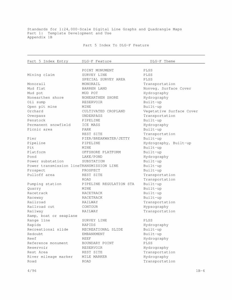
Part 5 Index To DLG-F Feature
Part 5 Index Entry DLG-F Feature DLG-F Theme
Standards for 1:24,000-Scale Digital Line Graphs and Quadrangle MapsPart 1: Template Development and UseAppendix 1B
4/96 1B-3
Airboat Trail LANE TransportationAirport AIRCRAFT FACILITY TransportationAlkali flat BARREN LAND Nonveg. Surface Cover
PLAYA Hydrography Apron RUNWAY/APRON/TAXIWAY TransportationAqueduct CANAL/DITCH Hydrography
PIPELINE HydrographyArcheological site ARCHEOLOGICAL SITE/RUIN Built-up Area between shoreline and sounding datum line FORESHORE HydrographyArea limits CABLE/PIPELINE SITE Built-up Area to be submerged AREA TO BE SUBMERGED HydrographyAthletic field ATHLETIC FIELD Built-up Bathymetric contour CONTOUR (BATHYMETRIC) Topo-bathy onlyBattle trench EMBANKMENT Built-upBeach, gravel BARREN LAND Nonveg. Surface Cover Beacon TOWER Built-upBench markBoardwalk BOARDWALK Built-upBoat ramp LAUNCHING RAMP Built-up Boundary BOUNDARY LINE Boundaries Boundary monument BOUNDARY POINT Boundaries
POINT MONUMENT Boundaries Breakwater PIER/BREAKWATER/JETTY Built-up Breastworks EMBANKMENT Built-upBridge BRIDGE Transportation, HydrographyBuilding BUILDING Built-up Built-up area BUILT-UP AREA Built-upCableway CABLEWAY Built-upCampground CAMPGROUND Built-up Campsite CAMPGROUND Built-up Canal CANAL/DITCH HydrographyCanal lock GATE HydrographyCarline RAILWAY TransportationCarolina bay BASIN Named LandformsCauseway PIER/BREAKWATER/JETTY Built-up Cave entrance CAVE ENTRANCE Named Landforms Cemetery CEMETERY Built-up Channel LANE TransportationCliff dwelling ARCHEOLOGICAL SITE/RUIN Built-up Cog railway RAILWAY TransportationCoke ovens KILN Built-up

Part 5 Index To DLG-F Feature
Part 5 Index Entry DLG-F Feature DLG-F Theme
Standards for 1:24,000-Scale Digital Line Graphs and Quadrangle MapsPart 1: Template Development and UseAppendix 1B
4/96 1B-4
College BUILDING Built-upINSTITUTIONAL SITE Built-up
Compressor station PIPELINE REGULATION STA. Built-upContinental Divide DIVIDE Named LandformsContour CONTOUR HypsographyControl pointConveyor CONVEYOR Built-upCoral reef REEF HypsographyCorral HOLDING PEN Built-upCranberry bog CULTIVATED CROPLAND Vegetative Surface Cover Crevasse field CREVASSE FIELD HydrographyCul-de-sac CUL DE SAC Transportation
ROAD TransportationCut CONTOUR HypsographyDam DAM/WEIR HydrographyDike EMBANKMENT Built-up Ditch CANAL/DITCH HydrographyDiversion dam DAM/WEIR HydrographyDonation land claim PLSS AREA PLSS Drawbridge DRAW SPAN TransportationDrive-in theater OUTDOOR THEATER Built-up
DRIVE-IN THEATER SCREEN Built-upDry lake or pond PLAYA Hydrography
BARREN LAND Nonveg. Surface CoverDrydock DRYDOCK Built-up Duck pond INUNDATION AREA HydrographyDune area DUNES Nonveg. Surface Cover Evaporator RESERVOIR HydrographyFeedlot HOLDING PEN Built-upFence line FENCE LINE Built-up Ferry LANE TransportationField line FENCE LINE Built-upFish hatchery AQUACULTURE SITE Built-up Fish ladder FISH LADDER HydrographyFlat PLAYA Hydrography
FORESHORE HydrographyFloodgate GATE HydrographyFlume FLUME HydrographyFootbridge BRIDGE TransportationFord FORD TransportationForeshore flat FORESHORE HydrographyFound closing corner SURVEY CORNER PLSSFound section corner SURVEY CORNER PLSS

Part 5 Index To DLG-F Feature
Part 5 Index Entry DLG-F Feature DLG-F Theme
Standards for 1:24,000-Scale Digital Line Graphs and Quadrangle MapsPart 1: Template Development and UseAppendix 1B
4/96 1B-5
Fumarole FUMAROLE HydrographyGaging station GAGING STATION HydrographyGeyser GEYSER HydrographyGlacial moraine MORAINE Nonveg. Surface Cover Glacier ICE MASS HydrographyGrave CEMETERY Built-up Gravel beach BARREN LAND Nonveg. Surface CoverHelipad AIRCRAFT FACILITY Transportation
HELIPAD TransportationHighway ROAD TransportationHoliday areaHomestead monument SURVEY CORNER PLSSHoriz Control Sta.House of worship BUILDING Built-upInadequate survey areaIncline railway RAILWAY TransportationIntertidal zone FORESHORE HydrographyJetty PIER/BREAKWATER/JETTY Built-up Lake LAKE/POND HydrographyLand grant line LAND GRANT PLSS
SURVEY LINE PLSS Land grant monument SURVEY CORNER PLSS
POINT MONUMENT PLSSLand subj inundation INUNDATION AREA HydrographyLanding strip RUNWAY/APRON/TAXIWAY TransportationLandmark object see specific feature Lava INCLINE/FLOW Named Landforms
BARREN LAND Nonveg. Surface CoverLevee EMBANKMENT Built-up Located object see specific featureLocation monument SURVEY CORNER PLSS
POINT MONUMENT PLSS Mangrove TREES Vegetative Surface Cover
SWAMP/MARSH Hydrography Marsh SWAMP/MARSH HydrographyMeander Corner SURVEY CORNER PLSS Mine dump DISPOSAL SITE Built-up entrance MINE ENTRANCE Built-up open pit MINE Built-up shaft MINE ENTRANCE Built-up strip MINE Built-upMineral monument SURVEY POINT PLSS
Part 5 Index To DLG-F Feature
Part 5 Index Entry DLG-F Feature DLG-F Theme
Standards for 1:24,000-Scale Digital Line Graphs and Quadrangle MapsPart 1: Template Development and UseAppendix 1B
4/96 1B-6
POINT MONUMENT PLSS Mining claim SURVEY LINE PLSS
SPECIAL SURVEY AREA PLSSMonorail MONORAIL TransportationMud flat BARREN LAND Nonveg. Surface Cover Mud pot MUD POT HydrographyNonearthen shore NONEARTHEN SHORE HydrographyOil sump RESERVOIR Built-up Open pit mine MINE Built-up Orchard CULTIVATED CROPLAND Vegetative Surface Cover Overpass UNDERPASS TransportationPenstock PIPELINE Built-up Permanent snowfield ICE MASS HydrographyPicnic area PARK Built-up
REST SITE TransportationPier PIER/BREAKWATER/JETTY Built-up Pipeline PIPELINE Hydrography, Built-up Pit MINE Built-upPlatform OFFSHORE PLATFORM Built-upPond LAKE/POND HydrographyPower substation SUBSTATION Built-upPower transmission lineTRANSMISSION LINE Built-upProspect PROSPECT Built-up Pulloff area REST SITE Transportation
ROAD TransportationPumping station PIPELINE REGULATION STA Built-up Quarry MINE Built-up Racetrack RACETRACK Built-up Raceway RACETRACK Built-up Railroad RAILWAY TransportationRailroad cut CONTOUR HypsographyRailway RAILWAY TransportationRamp, boat or seaplaneRange line SURVEY LINE PLSS Rapids RAPIDS HydrographyRecreational slide RECREATIONAL SLIDE Built-up Redoubt EMBANKMENT Built-upReef REEF HydrographyReference monument BOUNDARY POINT PLSS Reservoir RESERVOIR Hydrography Rest Area REST SITE TransportationRiver mileage marker MILE MARKER HydrographyRoad ROAD Transportation

Part 5 Index To DLG-F Feature
Part 5 Index Entry DLG-F Feature DLG-F Theme
Standards for 1:24,000-Scale Digital Line Graphs and Quadrangle MapsPart 1: Template Development and UseAppendix 1B
4/96 1B-7
Road cut CONTOUR HypsographyRoadside park REST SITE TransportationRock ROCK HydrographyRocks, group of HAZARD ZONE HydrographyRoundhouse BUILDING Built-up Ruins ARCHEOLOGICAL SITE/RUINS Built-up Runways RUNWAY/APRON/TAXIWAY TransportationSand BARREN LAND Nonveg. Surface CoverSand Dunes DUNES Nonveg. Surface CoverSand in open water BARREN LAND Nonveg. Surface Cover School BUILDING Built-up
INSTITUTIONAL SITE Built-up Scrub SHRUBLAND Vegetative Surface Cover Seaplane Landing Area LANE TransportationSeaplane ramp LAUNCHING RAMP Built-upSeawall WALL Built-up Section line SURVEY LINE PLSS Seep SPRING/SEEP HydrographyService area REST SITE TransportationSewage disposal plant SEWAGE DISPOSAL PLANT Built-up
RESERVOIR Built-upSewerline, submerged PIPELINE Built-up Shoal HAZARD ZONE Hydrography
BAR Named LandformsShoreline SHORELINE HydrographySiphon PIPELINE HydrographySki lift CABLEWAY Built-up Sludge pit RESERVOIR Built-up Sluice gate GATE HydrographySnowfield, permanent ICE MASS HydrographySnowshed BUILDING Built-up Sounding datum line Sounding Datum Line HydrographySpecial survey mon. SURVEY CORNER PLSSSpillway SPILLWAY HydrographySpoil area SPECIAL USE ZONE HydrographySpoil bank EMBANKMENT Built-up Spot elevation SPOT ELEVATION HypsographySpring SPRING/SEEP HydrographyStockyard HOLDING PEN Built-upStream STREAM/RIVER HydrographySwamp SWAMP/MARSH HydrographySwimming pool RESERVOIR HydrographyTailings DISPOSAL SITE Built-up

Part 5 Index To DLG-F Feature
Part 5 Index Entry DLG-F Feature DLG-F Theme
Standards for 1:24,000-Scale Digital Line Graphs and Quadrangle MapsPart 1: Template Development and UseAppendix 1B
4/96 1B-8
Tailings pond RESERVOIR HydrographyTank TANK Built-up Taxiway RUNWAY/APRON/TAXIWAY TransportationTelephone line TRANSMISSION LINE Built-up Tennessee Valley Divide DIVIDE Named LandformsTide Station GAGING STATION HydrographyTidegate GATE HydrographyTollgate GATE TransportationTownship line SURVEY LINE PLSS Tract PLSS AREA PLSSTraffic circle ROAD TransportationTrail TRAIL TransportationTrees, scattered TREES Vegetative Surface CoverTunnel TUNNEL Hydrography, TransportationTurntable TURNTABLE TransportationUnderpass UNDERPASS Hydrography, TransportationUniversity INSTITUTIONAL SITE Built-up Valve station PIPELINE REG. STA. Built-upVert control sta.Vineyard CULTIVATED CROPLAND Vegetative Surface Cover Wall WALL Hydrography, Built-up Wash WASH HydrographyWater filtration plant FILTRATION PLANT Built-up
RESERVOIR HydrographyWaterfall WATERFALL HydrographyWeir DAM/WEIR HydrographyWell WELL Hydrography, Built-upWharf WHARF Built-up Wind generator WINDMILL Built-up Windmill WINDMILL Built-up Witness corner SURVEY CORNER PLSS Wooded swamp SWAMP/MARSH Hydrography
TREES Vegetative Surface CoverWoods TREES Vegetative Surface Cover Wreck WRECK Hydrography
HAZARD ZONE HydrographyWreckage, exposed HAZARD ZONE Hydrography

Standards for 1:24,000-Scale Digital Line Graphs and Quadrangle MapsPart 1: Template Development and UseAppendix 1C
4/96 1C-1
APPENDIX 1C
Part 6 (Supplementary Publication Symbols) Index to DLG-F Feature

Standards for 1:24,000-Scale Digital Line Graphs and Quadrangle MapsPart 1: Template Development and UseAppendix 1C
4/96 1C-2
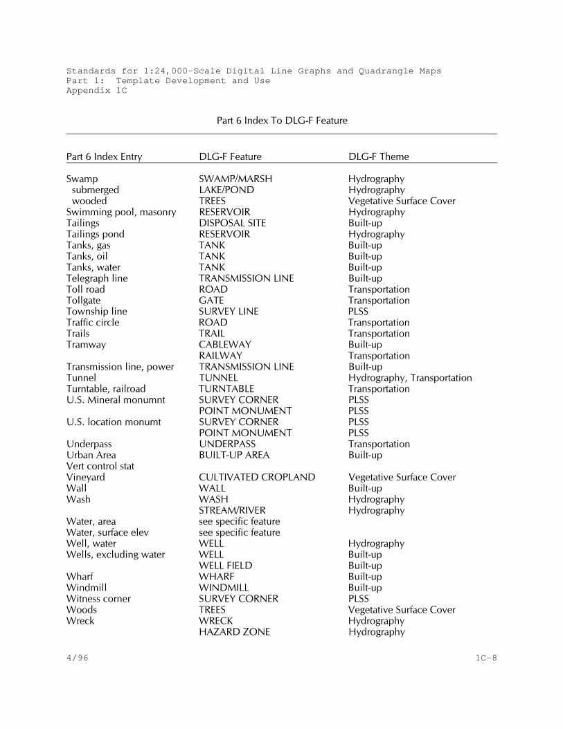
The following table is provided as an aid in trans lating the symbol
labels listed in the index to Part 6: Supplementary Publication
Symbols of Standards for 1:24,000- and 1:25,000-Scale Quadrangle
Maps to DLG-F features. This table is only to direct the user to
the appropriate feature template and does not imply that the feature
indicated is the correct feature in all cases. This table is based
on the version of Part 6 that includes Change Notice Number 8.

Part 6 Index To DLG-F Feature
Part 6 Index Entry DLG-F Feature DLG-F Theme
Standards for 1:24,000-Scale Digital Line Graphs and Quadrangle MapsPart 1: Template Development and UseAppendix 1C
4/96 1C-3
Alkali flat BARREN LAND Nonveg. Surface Cover PLAYA Hydrography
Aqueduct CANAL/DITCH HydrographyPIPELINE Hydrography
Area limits CABLE/PIPELINE SITE Built-up Area to be submerged AREA TO BE SUBMERGED HydrographyBeach, gravel BARREN LAND Nonveg. Surface Cover
BEACH Nonveg. Surface CoverBench markBoardwalk BOARDWALK Built-upBorrow pit MINE Built-up Boundary BOUNDARY LINE Boundaries Boundary monument BOUNDARY POINT Boundaries
POINT MONUMENT Boundaries with number & elevation SPOT ELEVATION Hypsography
Breakwater PIER/BREAKWATER/JETTY Built-up Bridge BRIDGE Transportation, HydrographyBrushwood SHRUBLAND Vegetative Surface Cover Buildings BUILDING Built-up Campground CAMPGROUND Built-up Canal, contouring at CONTOUR HypsographyCarline RAILWAY TransportationCauseway PIER/BREAKWATER/JETTY Built-up Cave CAVE ENTRANCE Named Landforms Cemetery CEMETERY Built-up Channel LANE TransportationChurch BUILDING Built-up Clay pit MINE Built-up Cliff dwelling ARCHEOLOGICAL SITE/RUIN Built-up Closing corner SURVEY CORNER PLSS Cloverleaf ROAD TransportationCoke ovens KILN Built-up College INSTITUTIONAL SITE Built-up
BUILDING Built-up Conduit, elevated PIPELINE Built-upContour CONTOUR HypsographyControl pointsCoral Reef REEF HydrographyCranberry bog CULTIVATED CROPLAND Vegetative Surface Cover Crevasses, glacial CREVASSE FIELD HydrographyCut CONTOUR Hypsography

Part 6 Index To DLG-F Feature
Part 6 Index Entry DLG-F Feature DLG-F Theme
Standards for 1:24,000-Scale Digital Line Graphs and Quadrangle MapsPart 1: Template Development and UseAppendix 1C
4/96 1C-4
Dam DAM/WEIR HydrographyDanger curve HAZARD ZONE HydrographyDead end road not collectedDepth curve DEPTH CURVE HydrographyDestination arrow Direction arrow
Disappearing stream SINK/RISE HydrographyDitch CANAL/DITCH HydrographyDolphin POST HydrographyDrawbridge DRAW SPAN TransportationDrive-in theater OUTDOOR THEATER Built-up
DRIVE-IN THEATER SCREEN Built-up Dry lake FLAT Hydrography
BARREN LAND Nonveg. Surface CoverDry pond FLAT Hydrography
BARREN LAND Nonveg. Surface CoverDrydock DRYDOCK Built-up Dune area DUNES Nonveg. Surface Cover
BARREN LAND Nonveg. Surface CoverElevations
CONTOUR HypsographySPOT ELEVATION Hypsography
water surface AREA TO BE SUBMERGED HydrographyCANAL/DITCH HydrographyINUNDATION AREA HydrographyLAKE/POND HydrographySTREAM/RIVER Hydrography
Exposed Wreck WRECK HydrographyExposed Wreckage HAZARD ZONE Hydrography
WRECK HydrographyFalls WATERFALL HydrographyFence line FENCE LINE Built-up Ferry LANE TransportationFiltration plant FILTRATION PLANT Built-up
RESERVOIR Hydrography Fish hatchery AQUACULTURE SITE Built-up Flat FLAT Hydrography
BARREN LAND Nonveg. Surface CoverFORESHORE Hydrography
Flume FLUME HydrographyFootbridge BRIDGE Transportation

Part 6 Index To DLG-F Feature
Part 6 Index Entry DLG-F Feature DLG-F Theme
Standards for 1:24,000-Scale Digital Line Graphs and Quadrangle MapsPart 1: Template Development and UseAppendix 1C
4/96 1C-5
Ford FORD TransportationForeshore flat FORESHORE HydrographyFoul ground HAZARD ZONE HydrographyGaging station GAGING STATION HydrographyGas pipeline PIPELINE Built-up Glacial crevasses CREVASSE FIELD HydrographyGlacial moraine MORAINE Nonveg. Surface Cover Glacier ICE MASS HydrographyGravel BARREN LAND Nonveg. Surface Cover Gravel beach BEACH Nonveg. Surface Cover
BARREN LAND Nonveg. Surface Cover Gravel pit MINE Built-up Horiz control statIntricate surface area DISTURBED SURFACE Built-up Inundation,land subject to INUNDATION AREA HydrographyJetty PIER/BREAKWATER/JETTY Built-up Lake LAKE/POND Hydrography dry FLAT Hydrography
BARREN LAND Nonveg. Surface CoverLand grant LAND GRANT PLSS
SURVEY LINE PLSS Land grant monument POINT MONUMENT PLSS
SURVEY CORNER PLSS Land subj inundation INUNDATION AREA HydrographyLandmark object see specific feature Lanes, roads ROAD TransportationLevee EMBANKMENT Built-up Located object see specific feature Lock GATE HydrographyMangrove TREES Vegetative Surface Cover
SWAMP/MARSH Hydrography Marsh SWAMP/MARSH Hydrography
submerged LAKE/POND Hydrography wooded TREES Vegetative Surface CoverMasts, exposed WRECK Hydrography
HAZARD ZONE HydrographyMeander Corner SURVEY CORNER PLSS Mine
areal strip MINE Built-up dump DISPOSAL SITE Built-up

Part 6 Index To DLG-F Feature
Part 6 Index Entry DLG-F Feature DLG-F Theme
Standards for 1:24,000-Scale Digital Line Graphs and Quadrangle MapsPart 1: Template Development and UseAppendix 1C
4/96 1C-6
linear strip MINE Built-up open pit MINE Built-up shaft MINE ENTRANCE Built-up tunnel entrance MINE ENTRANCE Built-up
Mining claim SURVEY LINE PLSS SPECIAL SURVEY AREA PLSS
Mud BARREN LAND Nonveg. Surface Cover Oil
pipeline PIPELINE Built-up reservoir, open RESERVOIR Built-up sump RESERVOIR Built-up
Orchard CULTIVATED CROPLAND Vegetative Surface Cover Overpass UNDERPASS TransportationPenstock, underground PIPELINE Built-up Picnic area PARK Built-up
REST SITE TransportationPier PIER/BREAKWATER/JETTY Built-up Pile HAZARD ZONE Hydrography
POST HydrographyPond LAKE/POND Hydrography dry FLAT Hydrography
BARREN LAND Nonveg. Surface CoverPower trans. line TRANSMISSION LINE Built-up Prospect PROSPECT Built-up Pumping station PIPELINE REGULATION STA Built-up Quarry MINE Built-up Railroad RAILWAY Transportation
dismantled TRAIL Transportationsiding RAILWAY Transportationstation BUILDING Built-up yard RAILWAY YARD Transportation
Railway, incline RAILWAY TransportationRange line SURVEY LINE PLSS Rapids RAPIDS HydrographyReef REEF HydrographyReference monument BOUNDARY POINT Boundaries Reservoir RESERVOIR Built-up, HydrographyRice field CULTIVATED CROPLAND Vegetative Surface Cover Road ROAD TransportationRock ROCK HydrographyRoundhouse BUILDING Built-up Route markers ROUTE Transportation

Standards for 1:24,000-Scale Digital Line Graphs and Quadrangle MapsPart 1: Template Development and UseAppendix 1C
Part 6 Index To DLG-F Featu re
Part 6 Index Entry DLG-F Featu re DLG-F Theme
4/01 1C-7
Railway, incline RAILWAY TransportationRange line SURVEY LIN E PLS S Rapi ds RA PIDS Hydrograph yReef REEF Hydrograph yReference monument BOUNDA RY POINT Boundaries Reservoir RESERVOIR Built- up, Hydrograph yRoad ROAD Tran sportati onRock ROCK Hydrograph yRoundhouse BUILDING Built- up Route markers ROUTE Tran sportationRuins ARCHEOLOGICAL S ITE/R UINS Built-u p Salt evaporator RESERVOIR HydrographySand area BARREN LAND Nonveg. Su rface Cover
DUNES Nonveg. Su rface CoverSand, in open water BARREN LAND Nonveg. Su rface CoverSand, shifting DUNES Nonveg. Su rface Cover Sand pit, large MINE Built-up School BUILDING Built- up
INSTITUTIONAL SITE Built-u p Scrub SHRUBLA ND Vegetati ve Surf ace Cover Seawall WALL Built-u p Section corner SURVEY CORNER PLSS Section line SURVEY LIN E PLS S Sewage disposal RESERVOIR Hydrograph ySewage disposal plant SEWAGE DISPOSAL PLANT Built-u p Shoal HAZARD ZONE Hydrography
BAR Named Lan dformsShoreline SHORELINE Hydrograph ySiphon PIPELINE Hydrograph ySki lif t CABLEWA Y Built- up Sludge pit RESERVOIR Built- up Sluice gate GATE Hydrograph ySnag HAZA RD ZONE Hydrograph ySnowfield, perman ent ICE MA SS Hydrograph ySnowshed BUILDING Built- upSoundings SOUNDING Hypsography Spoil bank EMBA NKMENT Built- up Spot elevation SPOT ELEVA TION Hypsograph y
Part 6 Index To DLG-F Feature
Part 6 Index Entry DLG-F Feature DLG-F Theme
Standards for 1:24,000-Scale Digital Line Graphs and Quadrangle MapsPart 1: Template Development and UseAppendix 1C
4/96 1C-8
Swamp SWAMP/MARSH Hydrography submerged LAKE/POND Hydrography wooded TREES Vegetative Surface CoverSwimming pool, masonry RESERVOIR HydrographyTailings DISPOSAL SITE Built-up Tailings pond RESERVOIR HydrographyTanks, gas TANK Built-up Tanks, oil TANK Built-up Tanks, water TANK Built-up Telegraph line TRANSMISSION LINE Built-up Toll road ROAD TransportationTollgate GATE TransportationTownship line SURVEY LINE PLSS Traffic circle ROAD TransportationTrails TRAIL TransportationTramway CABLEWAY Built-up
RAILWAY TransportationTransmission line, power TRANSMISSION LINE Built-up Tunnel TUNNEL Hydrography, TransportationTurntable, railroad TURNTABLE TransportationU.S. Mineral monumnt SURVEY CORNER PLSS
POINT MONUMENT PLSS U.S. location monumt SURVEY CORNER PLSS
POINT MONUMENT PLSSUnderpass UNDERPASS TransportationUrban Area BUILT-UP AREA Built-up Vert control statVineyard CULTIVATED CROPLAND Vegetative Surface Cover Wall WALL Built-up Wash WASH Hydrography
STREAM/RIVER HydrographyWater, area see specific feature Water, surface elev see specific feature Well, water WELL HydrographyWells, excluding water WELL Built-up
WELL FIELD Built-up Wharf WHARF Built-up Windmill WINDMILL Built-up Witness corner SURVEY CORNER PLSS Woods TREES Vegetative Surface Cover Wreck WRECK Hydrography
HAZARD ZONE Hydrography

Part 6 Index To DLG-F Feature
Part 6 Index Entry DLG-F Feature DLG-F Theme
Standards for 1:24,000-Scale Digital Line Graphs and Quadrangle MapsPart 1: Template Development and UseAppendix 1C
4/96 1C-9
Wreckage, exposed HAZARD ZONE Hydrography

Standards for 1:24,000-Scale Digital Line Graphs and Quadrangle MapsPart 1: Template Development and UseAppendix 1D
4/96 1D-1
APPENDIX 1D
DLG-F Feature to DLG-3 Code Crosswalk

Standards for 1:24,000-Scale Digital Line Graphs and Quadrangle MapsPart 1: Template Development and UseAppendix 1D
4/96 1D-2
The following table provides a guide to aid in the translation of
DLG-F features to DLG-3 codes. This table is intended only to
direct the user to the appropriate DLG-3 code and does not imply
that the code indicated is the correct code in all cases. The
user must rely on the DLG-3 documentation and the feature template
to determine the correct feature and its associated DLG-3 code.
This table is based on the 7/95 version of Part 3: Attribute
Coding of Standards for Digital Line Graphs.

Standards for 1:24,000-Scale Digital Line Graphs and Quadrangle MapsPart 1: Template Development and UseAppendix 1D
4/96 1D-3
DL
G-F
Fe
atu
re t
o D
LG
-3 C
od
e C
ross
wa
lk(H
ydro
gra
ph
y T
he
me
)
DL
G-F
Fe
atu
reD
LG
-3 C
od
eD
LG
-3 D
efin
itio
n
Are
a o
f C
om
ple
x C
ha
nn
els
05
0 0
41
3B
raid
ed
Str
ea
mA
rea
to
be
Su
bm
erg
ed
05
0 0
10
8A
rea
to
be
Su
bm
erg
ed
Ba
y/In
let
No
co
de
Bri
dg
e0
50
06
02
Ove
rpa
ssin
g1
70
02
13
Fo
otb
rid
ge
17
0 0
00
1B
rid
ge
Ab
utm
en
t1
70
06
12
Do
ub
le-D
eck
ed
17
0 0
61
8O
n D
raw
bri
dg
e1
70
06
02
Ove
rpa
ssin
g,
On
Bri
dg
e1
80
00
01
Bri
dg
e A
bu
tme
nt
18
0 0
61
1O
n D
raw
bri
dg
e1
80
06
02
Ove
rpa
ssin
g,
On
Bri
dg
eC
an
al/D
itch
05
0 0
41
4D
itch
or
Ca
na
l0
50
04
15
Aq
ue
du
ct o
r P
ipe
line
Co
nn
ect
or
No
co
de
Cre
vass
e F
ield
05
0 0
41
1C
reva
sse
(G
laci
al)
Da
m/W
eir
05
0 0
40
6D
am
or
We
irE
stu
ary
05
0 0
11
6B
ay,
Est
ua
ry,
Gu
lf, O
cea
n,
Se
aF
ish
La
dd
er
05
0 0
42
5F
ish
La
dd
er
Fo
resh
ore
05
0 0
11
5F
lats
(T
ida
l, M
ud
, S
an
d,
or
Gra
vel)
Flu
me
05
0 0
41
6F
lum
eF
um
aro
le0
50
03
04
Ge
yse
rG
ag
ing
Sta
tion
05
0 0
40
3G
ag
ing
Sta
tion
Ga
te0
50
04
09
Ga
te
Ge
yse
r 0
50
03
04
Ge
yse
rH
aza
rd Z
on
e0
50
02
06
Lim
itin
g D
an
ge
r L
ine
05
0 0
11
7S
ho
al
05
0 0
12
5F
ou
l Gro
un
d0
50
01
26
Min
e D
an
ge
r A
rea
05
0 0
41
0R
ock
20
0 0
46
7E
xpo
sed
Wre
ck o
r W
reck
ag
e2
00
04
68
Su
nke
n W
reck
20
0 0
46
5P
ile,
Do
lph
in,
Stu
mp
, o
r S
na
g

Standards for 1:24,000-Scale Digital Line Graphs and Quadrangle MapsPart 1: Template Development and UseAppendix 1D
4/96 1D-4
DL
G-F
Fe
atu
re t
o D
LG
-3 C
od
e C
ross
wa
lk(H
ydro
gra
ph
y T
he
me
)
DL
G-F
Fe
atu
reD
LG
-3 C
od
eD
LG
-3 D
efin
itio
n
Ice
Ma
ss0
50
01
03
Gla
cie
r o
r P
erm
an
en
t S
no
wfie
ldIn
un
da
tion
Are
a0
50
01
19
Du
ck P
on
d0
50
01
05
Inu
nd
atio
n A
rea
La
ke/P
on
d0
50
04
21
La
ke o
r P
on
dL
ock
Ch
am
be
r0
50
04
07
Lo
ck C
ha
mb
er
Mile
Ma
rke
r0
55
---
-R
ive
r M
ile M
ark
er
Mu
d P
ot
05
0 0
30
4G
eys
er
No
ne
art
he
n S
ho
re0
50
02
01
Ma
nm
ad
e S
ho
relin
eP
ipe
line
05
0 0
41
7P
en
sto
ck0
50
04
18
Sip
ho
n0
50
04
15
Aq
ue
du
ct o
r P
ipe
line
Pla
ya0
50
01
00
Alk
ali
Fla
t0
50
04
21
La
ke o
r P
on
d (
dry
)P
ost
20
0 0
46
5P
ile,
Do
lph
in,
Stu
mp
, o
r S
na
gR
ap
ids
05
0 0
40
0R
ap
ids
Re
ef
05
0 0
42
2R
ee
fR
ese
rvo
ir0
50
01
01
Re
serv
oir
05
0 0
10
2C
ove
red
Re
serv
oir
05
0 0
10
4S
alt
Eva
po
rato
r0
50
01
06
Aq
ua
cultu
re P
on
d0
50
01
07
Ind
ust
ria
l Wa
ter
Imp
ou
nd
me
nt
05
0 0
10
9S
ew
ag
e D
isp
osa
l Po
nd
05
0 0
11
0T
aili
ng
s P
on
d0
50
01
24
Filt
ratio
n P
on
d
05
0 0
11
8S
od
a E
vap
ora
tor
20
0 0
45
1S
wim
min
g P
oo
l

Standards for 1:24,000-Scale Digital Line Graphs and Quadrangle MapsPart 1: Template Development and UseAppendix 1D
4/01 1D-5
DLG-FFeaturetoDLG-3CodeCrosswalk
(HydrographyTheme)
DLG-FFeature
DLG-3Code
DLG-3Definition
Rock
0500410
Rock
Sea/Ocean
0500116
Bay,Estuary,Gulf,Ocean,orSea
0500122
Gut
Shoreline
0500207
ApparentShoreline
Bridge
0500203
IndefiniteShoreline
0500209
Low-WaterLine
0500200
Shoreline
0500605
RightBank
0500606
LeftBank
Sink/Rise
0500003
Sink
Snag/Stump
2000465
Pile,Dolphin,Stump,orSnag
SoundingDatumLine
0500208
SoundingDatum
SpecialUseZone
0500424
SpoilArea,DredgedArea,orDump
Area
SpecialUseZoneLimit
Nocode
Spillway
0500408
Spillway
Spring/Seep
0500300
Spring
Stream/River
0500413
BraidedStream
0500412
Stream
0500420
Wash
SubmergedStream
0500412
Stream(with0500612,Submergedor
Sunken
Swamp/Marsh
0500111
Marsh,Wetland,Swamp,orBog
0500112
MangroveArea
Tunnel
0500604
Tunnel
Underpass
0500617
Underpassing
0500602
Overpassing
Wash
0500420
Wash
WaterIntake/Outflow
0500303
Riser
0500405
WaterIntake
Watercourse
Nocode
Waterfall
0500401
Falls
Well
0500302
FlowingWell
0500301
NonflowingWell

Standards for 1:24,000-Scale Digital Line Graphs and Quadrangle MapsPart 1: Template Development and UseAppendix 1D
4/96 1D-6
DL
G-F
Fe
atu
re t
o D
LG
-3 C
od
e C
ross
wa
lk(T
ran
spo
rta
tion
Th
em
e)
DL
G-F
Fe
atu
reD
LG
-3 C
od
eD
LG
-3 D
efin
itio
n
Air
cra
ft F
aci
lity
No
co
de
B
rid
ge
17
0 0
21
3F
oo
tbri
dg
e1
70
06
18
On
Dra
wb
rid
ge
17
0 0
60
2O
verp
ass
ing
, O
n B
rid
ge
18
0 0
61
1O
n D
raw
bri
dg
e1
80
06
02
Ove
rpa
ssin
g,
On
Bri
dg
eC
ul-
De
-Sa
c1
70
00
05
Cu
l-D
e-S
ac
Dra
w S
pa
n1
70
00
07
Dra
wb
rid
ge
18
0 0
00
7D
raw
bri
dg
eF
ord
17
0 0
60
6S
ub
me
rge
d o
r in
Fo
rdG
ate
17
0 0
00
4G
ate
17
0 0
40
3T
ollg
ate
He
lipa
d1
90
04
04
He
lipa
dIn
terc
ha
ng
eN
o c
od
eL
an
e1
70
02
14
Ro
ad
Fe
rry
Cro
ssin
g1
80
02
07
Ra
ilro
ad
Fe
rry
Cro
ssin
gM
on
ora
il1
90
02
08
Mo
no
rail
Ra
ilwa
y1
80
02
01
Ra
ilro
ad
18
0 0
20
2R
ailr
oa
d in
Ro
ad
18
0 0
20
4C
arl
ine
18
0 0
20
8R
ailr
oa
d S
idin
g1
80
02
05
Co
g R
ailr
oa
d,
Incl
ine
Ra
ilwa
y, o
r L
og
gin
g T
ram
Ra
ilwa
y Y
ard
18
0 0
20
9R
ailr
oa
d Y
ard
Re
st S
ite2
00
04
53
Re
cre
atio
n A
rea
, P
ub
lic U
se A
rea
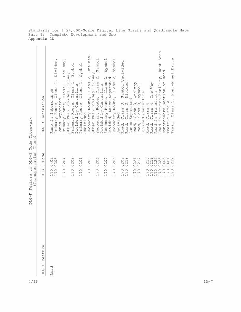
Standards for 1:24,000-Scale Digital Line Graphs and Quadrangle MapsPart 1: Template Development and UseAppendix 1D
4/96 1D-7
DL
G-F
Fe
atu
re t
o D
LG
-3 C
od
e C
ross
wa
lk(T
ran
spo
rta
tion
Th
em
e)
DL
G-F
Fe
atu
reD
LG
-3 C
od
eD
LG
-3 D
efin
itio
n
Ro
ad
17
0 0
40
2R
am
p in
In
terc
ha
ng
e1
70
02
03
Pri
ma
ry R
ou
te,
Cla
ss 1
, D
ivid
ed
, L
an
es
Se
pa
rate
d1
70
02
04
Pri
ma
ry R
ou
te,
Cla
ss 1
, O
ne
-Wa
y,
Oth
er
Th
an
Div
ide
d H
igh
wa
y1
70
02
02
Pri
ma
ry R
ou
te,
Cla
ss 1
, S
ymb
ol
Div
ide
d b
y C
en
terl
ine
17
0 0
20
1P
rim
ary
Ro
ute
, C
lass
1,
Sym
bo
l U
nd
ivid
ed
17
0 0
20
8S
eco
nd
ary
Ro
ute
, C
lass
2,
On
e W
ay,
O
the
r T
ha
n D
ivid
ed
Hig
hw
ay
17
0 0
20
6S
eco
nd
ary
Ro
ute
, C
lass
2,
Sym
bo
l D
ivid
ed
by
Ce
nte
rlin
e1
70
02
07
Se
con
da
ry R
ou
te,
Cla
ss 2
, S
ymb
ol
Div
ide
d,
La
ne
s S
ep
ara
ted
17
0 0
20
5S
eco
nd
ary
Ro
ute
, C
lass
2,
Sym
bo
l U
nd
ivid
ed
17
0 0
20
9R
oa
d,
Cla
ss 3
, S
ymb
ol U
nd
ivid
ed
17
0 0
21
8R
oa
d,
Cla
ss 3
, D
ivid
ed
, L
an
es
Se
pa
rate
d1
70
02
21
Ro
ad
, C
lass
3,
On
e W
ay
17
0 0
21
7R
oa
d,
Cla
ss 3
, S
ymb
ol
Div
ide
d C
en
terl
ine
17
0 0
21
0R
oa
d,
Cla
ss 4
17
0 0
21
9R
oa
d,
Cla
ss 4
, O
ne
Wa
y1
70
02
22
Ro
ad
in T
ran
sitio
n1
70
02
23
Ro
ad
in S
erv
ice
Fa
cilit
y, R
est
Are
a1
70
04
05
No
nst
an
da
rd S
ect
ion
of
Ro
ad
17
0 0
40
1T
raff
ic C
ircl
e1
70
02
12
Tra
il, C
lass
5,
Fo
ur-
Wh
ee
l Dri
ve

Standards for 1:24,000-Scale Digital Line Graphs and Quadrangle MapsPart 1: Template Development and UseAppendix 1D
4/96 1D-8
DL
G-F
Fe
atu
re t
o D
LG
-3 C
od
e C
ross
wa
lk(T
ran
spo
rta
tion
Th
em
e)
DL
G-F
Fe
atu
reD
LG
-3 C
od
eD
LG
-3 D
efin
itio
n
Ro
ute
No
co
de
Ru
nw
ay/
Ap
ron
/Ta
xiw
ay
19
0 0
40
3L
an
din
g S
trip
, R
un
wa
y, A
pro
n,
Ta
xiw
ay
Tra
ffic
In
spe
ctio
n F
aci
lity
17
0 0
40
4W
eig
h S
tatio
nT
rail
17
0 0
21
1T
rail
17
0 0
60
5L
ab
ele
d "
Old
Ra
ilro
ad
Gra
de
"T
un
ne
l1
70
06
01
In T
un
ne
l1
80
06
01
In T
un
ne
lT
un
ne
l En
tra
nce
17
0 0
00
2T
un
ne
l Po
rta
l1
80
00
02
Tu
nn
el P
ort
al
Tu
rnta
ble
18
0 0
40
1T
urn
tab
leU
nd
erp
ass
17
0 0
60
7U
nd
erp
ass
ing
18
0 0
60
5U
nd
erp
ass
ing
17
0 0
60
2
Ove
rpa
ssin
g,
On
Bri
dg
e1
80
06
02
Ove
rpa
ssin
g,
On
Bri
dg
e

Standards for 1:24,000-Scale Digital Line Graphs and Quadrangle MapsPart 1: Template Development and UseAppendix 1D
4/96 1D-9
DL
G-F
Fe
atu
re t
o D
LG
-3 C
od
e C
ross
wa
lk(B
ou
nd
ari
es
Th
em
e)
DL
G-F
Fe
atu
reD
LG
-3 C
od
eD
LG
-3 D
efin
itio
n
Bo
un
da
ry L
ine
09
0 0
20
2D
isp
ute
d B
ou
nd
ary
09
0 0
20
1In
de
finite
(o
r A
pp
roxi
ma
te)
Bo
un
da
ryB
ou
nd
ary
Lin
e o
r S
urv
ey
Lin
e0
90
02
03
His
tori
cal L
ine
Bo
un
da
ry P
oin
t0
90
00
01
Bo
un
da
ry M
on
um
en
t0
90
03
01
Re
fere
nce
Mo
nu
me
nt
for
Bo
un
da
ry C
ity0
90
01
01
Inco
rpo
rate
d C
ity,
Vill
ag
e,
To
wn
, B
oro
ug
h,
or
Ha
mle
tC
ou
nty
09
2 0
---
Co
un
ty o
r C
ou
nty
Eq
uiv
ale
nt
FIP
SC
od
e (
pa
ram
ete
r)M
ino
r C
ivil
Div
isio
n0
90
01
00
Civ
il T
ow
nsh
ip,
Dis
tric
t, P
reci
nct
,o
r B
arr
ioN
atio
n0
90
01
97
Ca
na
da
09
0 0
19
8M
exi
coP
oin
t M
on
um
en
tN
o c
od
eR
ese
rva
tion
09
0 0
15
0L
arg
e P
ark
(C
ity,
Co
un
ty,
Pri
vate
)0
90
01
51
Sm
all
Pa
rk (
City
, C
ou
nty
, P
riva
te)
09
0 0
13
4M
isc.
Co
un
ty R
ese
rva
tion
09
0 0
11
0F
ed
era
l Pri
son
09
0 0
13
6H
aw
aiia
n H
om
est
ea
d0
90
01
07
Ind
ian
Re
serv
atio
n0
90
01
08
Mili
tary
Re
serv
atio
n0
90
01
11
Mis
cella
ne
ou
s F
ed
era
l Re
serv
atio
n0
90
01
29
Mis
cella
ne
ou
s S
tate
Re
serv
atio
n0
90
01
04
Na
tion
al F
ore
st0
90
01
03
Na
tion
al P
ark
09
0 0
10
6N
atio
na
l Wild
ern
ess
Are
a0
90
01
32
Sta
te F
ore
st0
90
01
30
Sta
te P
ark
Re
serv
atio
n0
90
01
33
Sta
te P
riso
n0
90
01
31
Sta
te W
ildlif
e A
rea
09
0 0
10
5N
atio
na
l Wild
life
Are
aS
tate
/Te
rrito
ry0
91
00
--S
tate
or
Sta
te E
qu
iva
len
t F
IPS
Co
de
(pa
ram
ete
r)

Standards for 1:24,000-Scale Digital Line Graphs and Quadrangle MapsPart 1: Template Development and UseAppendix 1D
4/96 1D-10
DL
G-F
Fe
atu
re t
o D
LG
-3 C
od
e C
ross
wa
lk(P
LS
S T
he
me
)
DL
G-F
Fe
atu
reD
LG
-3 C
od
eD
LG
-3 D
efin
itio
n
La
nd
Gra
nt
30
0 0
10
3L
an
d G
ran
t3
00
01
06
Ove
rla
pp
ing
lan
d g
ran
tsP
oin
t M
on
um
en
tN
o c
od
eP
rin
cip
al M
eri
dia
nN
o c
od
eP
ub
lic L
an
d S
urv
ey
Su
rve
y A
rea
30
0 0
11
0P
LS
S A
rea
30
0 0
10
8P
riva
te s
urv
ey
in O
hio
30
0 0
10
4P
riva
te e
xte
nsi
on
s o
f p
ub
lic la
nd
surv
ey
30
0 0
10
5A
rea
of
pu
blic
an
d p
riva
te s
urv
ey
ove
rla
p3
00
01
02
Do
na
tion
lan
d c
laim
30
0 0
11
1T
ract
Sp
eci
al S
urv
ey
Are
a3
00
01
01
Ho
me
ste
ad
en
try
surv
ey
30
0 0
11
2U
.S.
Su
rve
y3
00
01
13
Ind
ian
allo
tme
nt
Su
rve
y C
orn
er
30
0 0
00
1F
ou
nd
PL
SS
se
ctio
n c
orn
er
30
0 0
00
4M
ea
nd
er
corn
er
30
0 0
00
7W
itne
ss c
orn
er
30
0 0
00
8W
itne
ss p
oin
t3
00
00
09
An
gle
po
int
30
0 0
01
0A
me
nd
ed
mo
nu
me
nt
30
0 0
01
2F
ou
nd
Qu
art
er-
sect
ion
co
rne
r3
00
00
14
La
nd
Gra
nt
or
oth
er
Sp
eci
al S
urv
ey
Co
rne
r3
00
03
01
Iso
late
d F
ou
nd
Se
ctio
n C
orn
er
30
0 0
30
0L
oca
tion
or
min
era
l mo
nu
me
nt
Su
rve
y L
ine
30
0 0
20
1A
pp
roxi
ma
te p
osi
tion
30
0 0
20
2P
rotr
act
ed
po
sitio
n3
00
02
03
Clo
sure
lin
e
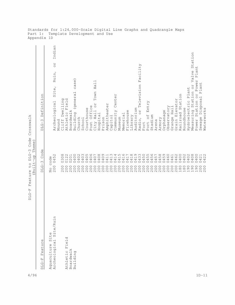
Standards for 1:24,000-Scale Digital Line Graphs and Quadrangle MapsPart 1: Template Development and UseAppendix 1D
4/96 1D-11
DL
G-F
Fe
atu
re t
o D
LG
-3 C
od
e C
ross
wa
lk(B
uilt
-up
Th
em
e)
DL
G-F
Fe
atu
reD
LG
-3 C
od
eD
LG
-3 D
efin
itio
n
Aq
ua
cultu
re S
iteN
o c
od
eA
rch
eo
log
ica
l Site
/Ru
in2
00
04
52
Arc
he
olo
gic
al
Site
, R
uin
, o
r In
dia
nM
ou
nd
20
0 0
30
8C
liff
Dw
elli
ng
Ath
letic
Fie
ld2
00
01
22
Ath
letic
Fie
ldB
oa
rdw
alk
20
0 0
20
1B
oa
rdw
alk
Bu
ildin
g2
00
04
00
Bu
ildin
g (
ge
ne
ral c
ase
)2
00
04
02
Ch
urc
h2
00
04
03
Sch
oo
l2
00
04
05
Co
urt
ho
use
20
0 0
40
6P
ost
Off
ice
20
0 0
40
7C
ity H
all
or
To
wn
Ha
ll2
00
04
08
Ho
spita
l2
00
04
09
Pri
son
20
0 0
41
1A
mp
hith
ea
ter
20
0 0
41
3C
ap
itol
20
0 0
41
4C
om
mu
nity
Ce
nte
r2
00
04
15
Mu
seu
m2
00
04
16
Me
mo
ria
l2
00
04
17
Fir
eh
ou
se2
00
04
18
Lib
rary
20
0 0
41
9A
ud
itori
um
20
0 0
43
3R
ad
io,
or
Te
levi
sio
n F
aci
lity
20
0 0
45
0F
ort
20
0 0
45
5P
ort
of
En
try
20
0 0
45
6S
tad
ium
20
0 0
45
7A
ren
a2
00
04
58
Arm
ory
20
0 0
45
9O
rph
an
ag
e2
00
04
60
Ob
serv
ato
ry2
00
04
61
Gra
ng
e H
all
20
0 0
46
2G
rain
Ele
vato
r1
80
04
00
Ra
ilro
ad
Sta
tion
18
0 0
40
2R
ou
nd
ho
use
19
0 0
40
2H
ydro
ele
ctri
c P
lan
t1
90
04
08
Me
asu
rin
g S
tatio
n o
r V
alv
e S
tatio
n1
90
04
00
Po
we
r S
tatio
n o
r P
ow
er
Pla
nt
20
0 0
42
1S
ew
ag
e D
isp
osa
l Pla
nt
20
0 0
42
2W
ate
rwo
rks

Standards for 1:24,000-Scale Digital Line Graphs and Quadrangle MapsPart 1: Template Development and UseAppendix 1D
4/96 1D-12
DL
G-F
Fe
atu
re t
o D
LG
-3 C
od
e C
ross
wa
lk(B
uilt
-up
Th
em
e)
DL
G-F
Fe
atu
reD
LG
-3 C
od
eD
LG
-3 D
efin
itio
n
Bu
ilt-u
p A
rea
20
0 0
15
0B
uilt
-Up
Are
aC
ab
le/P
ipe
line
Site
05
0 0
12
1O
bst
ruct
ion
are
a in
wa
ter
are
aC
ab
lew
ay
19
0 0
20
7A
eri
al T
ram
wa
y1
90
02
09
Ski
Lift
Ca
mp
gro
un
d2
00
04
49
Ca
mp
gro
un
d2
00
03
16
Ca
mp
site
Ce
me
tery
20
0 0
42
0C
em
ete
ryC
him
ne
y2
00
03
06
Bu
rne
r o
r st
ack
Co
nve
yor
20
0 0
20
0C
on
veyo
rD
ish
No
co
de
Dis
po
sal S
ite2
00
04
27
Min
e D
um
p2
00
01
63
Ta
ilin
gs
Dis
turb
ed
Su
rfa
ce2
00
01
64
Intr
ica
te S
urf
ace
Are
aD
rive
-In
Th
ea
ter
Scr
ee
n2
00
02
13
Scr
ee
n (
dri
ve-i
n t
he
ate
r)D
ryd
ock
Em
ba
nkm
en
t2
00
04
35
Le
vee
or
Dik
e2
00
04
36
Sp
oil
Ba
nk
Exh
ibiti
on
Gro
un
d2
00
04
45
Fa
irg
rou
nd
sF
en
ce L
ine
20
0 0
20
6F
en
ce L
ine
Filt
ratio
n P
lan
tN
o c
od
eH
isto
rica
l Mo
nu
me
nt
20
0 0
30
1H
isto
rica
l Ma
rke
rH
old
ing
Pe
n2
00
04
47
Co
rra
l2
00
01
81
Fe
ed
lot
or
Sto
ckya
rdIn
stitu
tion
al S
ite2
00
01
00
Ch
urc
h C
om
ple
x2
00
01
82
Exp
eri
me
nta
l Fa
rm2
00
01
02
He
alth
Ca
re C
om
ple
x2
00
01
03
Orp
ha
na
ge
Co
mp
lex
20
0 0
10
4P
riso
n C
om
po
un
d2
00
01
01
Sch
oo
l Ca
mp
us
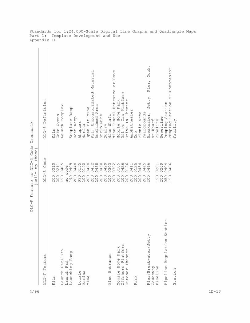
Standards for 1:24,000-Scale Digital Line Graphs and Quadrangle MapsPart 1: Template Development and UseAppendix 1D
4/96 1D-13
DL
G-F
Fe
atu
re t
o D
LG
-3 C
od
e C
ross
wa
lk(B
uilt
-up
Th
em
e)
DL
G-F
Fe
atu
reD
LG
-3 C
od
eD
LG
-3 D
efin
itio
n
Kiln
20
0 0
31
0K
iln2
00
02
11
Co
ke O
ven
sL
au
nch
Fa
cilit
y1
90
04
05
La
un
ch C
om
ple
xL
au
nch
Pa
dn
o c
od
eL
au
nch
ing
Ra
mp
19
0 0
40
9S
ea
pla
ne
Ra
mp
20
0 0
44
8B
oa
t R
am
pL
oca
le0
90
01
35
Ah
up
ua
aM
ari
na
20
0 0
14
0M
ari
na
Min
e2
00
04
28
Op
en
Pit
Min
e2
00
04
32
Pit,
Un
con
solid
ate
d M
ate
ria
l2
00
04
38
Re
cla
ime
d A
rea
20
0 0
43
0S
trip
Min
e2
00
04
29
Qu
arr
yM
ine
En
tra
nce
20
0 0
30
3M
ine
Sh
aft
20
0 0
30
2M
ine
Tu
nn
el E
ntr
an
ce o
r C
ave
Mo
bile
Ho
me
Pa
rk2
00
01
05
Mo
bile
Ho
me
Pa
rkO
ffsh
ore
Pla
tfo
rm2
00
04
26
Oil
or
Ga
s P
latf
orm
Ou
tdo
or
Th
ea
ter
20
0 0
12
6D
rive
-In
Th
ea
ter
20
0 0
41
1A
mp
hith
ea
ter
Pa
rk2
00
01
25
Zo
o2
00
04
54
Pic
nic
Are
a2
00
04
45
Fa
irg
rou
nd
sP
ier/
Bre
akw
ate
r/Je
tty
20
0 0
46
6B
rea
kwa
ter,
Je
tty,
Pie
r, D
ock
,C
au
sew
ay
or
Wh
arf
Pip
elin
e1
90
02
01
Pip
elin
e2
00
02
09
Se
we
rlin
eP
ipe
line
Re
gu
latio
n S
tatio
n0
50
04
04
Pu
mp
ing
Sta
tion
19
0 0
40
6P
um
pin
g S
tatio
n o
r C
om
pre
sso
rS
tatio
n
Fa
cilit
y
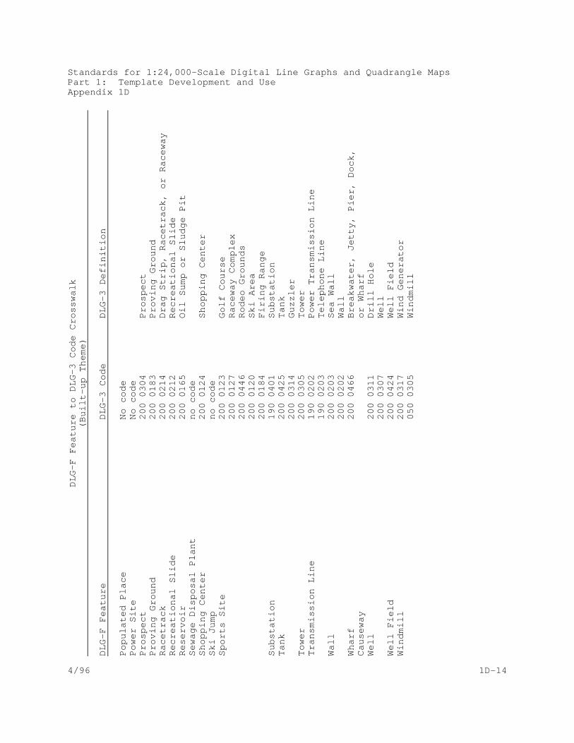
Standards for 1:24,000-Scale Digital Line Graphs and Quadrangle MapsPart 1: Template Development and UseAppendix 1D
4/96 1D-14
DL
G-F
Fe
atu
re t
o D
LG
-3 C
od
e C
ross
wa
lk(B
uilt
-up
Th
em
e)
DL
G-F
Fe
atu
reD
LG
-3 C
od
eD
LG
-3 D
efin
itio
n
Po
pu
late
d P
lace
No
co
de
Po
we
r S
iteN
o c
od
eP
rosp
ect
20
0 0
30
4P
rosp
ect
Pro
vin
g G
rou
nd
20
0 0
18
3P
rovi
ng
Gro
un
dR
ace
tra
ck2
00
02
14
Dra
g S
trip
, R
ace
tra
ck,
or
Ra
cew
ay
Re
cre
atio
na
l Slid
e2
00
02
12
Re
cre
atio
na
l Slid
eR
ese
rvo
ir2
00
01
65
Oil
Su
mp
or
Slu
dg
e P
itS
ew
ag
e D
isp
osa
l Pla
nt
no
co
de
Sh
op
pin
g C
en
ter
20
0 0
12
4S
ho
pp
ing
Ce
nte
rS
ki J
um
pn
o c
od
eS
po
rts
Site
20
0 0
12
3G
olf
Co
urs
e2
00
01
27
Ra
cew
ay
Co
mp
lex
20
0 0
44
6R
od
eo
Gro
un
ds
20
0 0
12
0S
ki A
rea
20
0 0
18
4F
irin
g R
an
ge
Su
bst
atio
n1
90
04
01
Su
bst
atio
nT
an
k2
00
04
25
Ta
nk
20
0 0
31
4G
uzz
ler
To
we
r2
00
03
05
To
we
rT
ran
smis
sio
n L
ine
19
0 0
20
2P
ow
er
Tra
nsm
issi
on
Lin
e1
90
02
03
Te
lep
ho
ne
Lin
eW
all
20
0 0
20
3S
ea
Wa
ll2
00
02
02
Wa
llW
ha
rf2
00
04
66
Bre
akw
ate
r, J
ett
y, P
ier,
Do
ck,
Ca
use
wa
y o
r W
ha
rfW
ell
20
0 0
31
1D
rill
Ho
le2
00
03
07
We
llW
ell
Fie
ld2
00
04
24
We
ll F
ield
Win
dm
ill2
00
03
17
Win
d G
en
era
tor
05
0 0
30
5W
ind
mill

Standards for 1:24,000-Scale Digital Line Graphs and Quadrangle MapsPart 1: Template Development and UseAppendix 1D
4/96 1D-15
DL
G-F
Fe
atu
re t
o D
LG
-3 C
od
e C
ross
wa
lk(H
ypso
gra
ph
y T
he
me
)
DL
G-F
Fe
atu
reD
LG
-3 C
od
eD
LG
-3 D
efin
itio
n
Co
nto
ur
(La
nd
)0
20
02
00
Co
nto
ur
02
0 0
20
1C
arr
yin
g C
on
tou
r0
20
02
02
Su
pp
lem
en
tary
Co
nto
ur
02
0 0
20
9O
bso
lete
Co
nto
ur
De
pth
Cu
rve
02
0 0
20
6D
ep
th C
urv
eS
ou
nd
ing
02
0 0
30
3S
ou
nd
ing
Sp
ot
Ele
vatio
n0
20
03
00
Sp
ot
Ele
vatio
n,
Le
ss T
ha
n T
hir
d
Ord
er,
gro
un
d le
vel
02
0 0
30
2S
po
t E
leva
tion
, L
ess
Th
an
Th
ird
O
rde
r, o
n b
rid
ge

Standards for 1:24,000-Scale Digital Line Graphs and Quadrangle MapsPart 1: Template Development and UseAppendix 1D
4/96 1D-16
DL
G-F
Fe
atu
re t
o D
LG
-3 C
od
e C
ross
wa
lk(N
on
-Ve
ge
tativ
e S
urf
ace
Co
ver
Th
em
e)
DL
G-F
Fe
atu
reD
LG
-3 C
od
eD
LG
-3 D
efin
itio
n
Ba
rre
n L
an
d0
50
01
00
Alk
ali
flat
05
0 0
11
5F
lat
05
0 0
42
0W
ash
05
0 0
63
0B
ou
lde
r 0
50
06
31
Sa
nd
0
50
06
32
Gra
vel
05
0 0
63
3R
ock
(fla
t o
r re
ef)
05
0 0
63
4M
ud
0
50
06
35
Sh
ell
05
0 0
63
6C
ora
l0
80
01
00
Gla
cia
l Mo
rain
e0
80
01
01
Gra
vel
Are
a0
80
01
02
Sa
nd
Are
a
08
0 0
10
4L
ava
Be
ach
08
0 0
10
1G
rave
l Are
a0
80
01
02
Sa
nd
Are
a
Du
ne
s0
80
01
02
Sa
nd
Are
aM
ora
ine
08
0 0
10
0G
laci
al M
ora
ine

Standards for 1:24,000-Scale Digital Line Graphs and Quadrangle MapsPart 1: Template Development and UseAppendix 1D
4/96 1D-17
DL
G-F
Fe
atu
re t
o D
LG
-3 C
od
e C
ross
wa
lk(V
eg
eta
tive
Su
rfa
ce C
ove
r T
he
me
)
DL
G-F
Fe
atu
reD
LG
-3 C
od
eD
LG
-3 D
efin
itio
n
Cu
ltiva
ted
Cro
pla
nd
07
0 0
10
3O
rch
ard
or
Pla
nta
tion
07
0 0
10
4V
ine
yard
05
0 0
11
4C
ran
be
rry
Bo
gS
hru
bla
nd
07
0 0
10
2S
cru
bT
ree
no
co
de
Tre
es
07
0 0
10
5S
catt
ere
d T
ree
s0
70
01
01
Wo
od
s o
r B
rush
wo
od
05
0 0
11
2M
an
gro
ve

Standards for 1:24,000-Scale Digital Line Graphs and Quadrangle MapsPart 1: Template Development and UseAppendix 1E
4/01 1E-1
APPENDIX 1E
DLG-3 Codes to DLG Feature Crosswalk

Standards for 1:24,000-Scale Digital Line Graphs and Quadrangle MapsPart 1: Template Development and UseAppendix 1E
4/96 1E-2
The following table is provided as an aid in the translating DLG-3
attribute codes to DLG-F features. This table is intended only to
direct the user to the appropriate feature template and does not
imply that the feature indicated is the correct feature in all
cases. The user must rely on the DLG-3 documentation and the
feature template to determine the correct feature and its associated
DLG-3 code. Generally, descriptive and parameter codes are not
presented in this table. Only those descriptive or parameter codes
that equate to a DLG-F feature are listed. Codes that are valid
only for USGS/FS Single-Edition products also do not appear. This
table is based on the 7/95 version of Part 3: Attribute Coding of
Standards for Digital Line Graphs.

Appendix 1E
DLG-3 Codes to DLG-F Feature Crosswalk(Hypsography - Major Code 020)
DLG-3 Code DLG-F Feature
Standards for 1:24,000-Scale Digital Line Graphs and Quadrangle MapsPart 1: Template Development and Use
4/96 1E-3
020 0200 Contour (Land)020 0201 Contour (Land)020 0202 Contour (Land)020 0205 Contour (Bathymetric)020 0206 Depth Curve020 0207 Divide020 0209 Contour (Land)020 0210 Contour (Bathymetric)020 0300 Spot Elevation020 0302 Spot Elevation 020 0303 Sounding
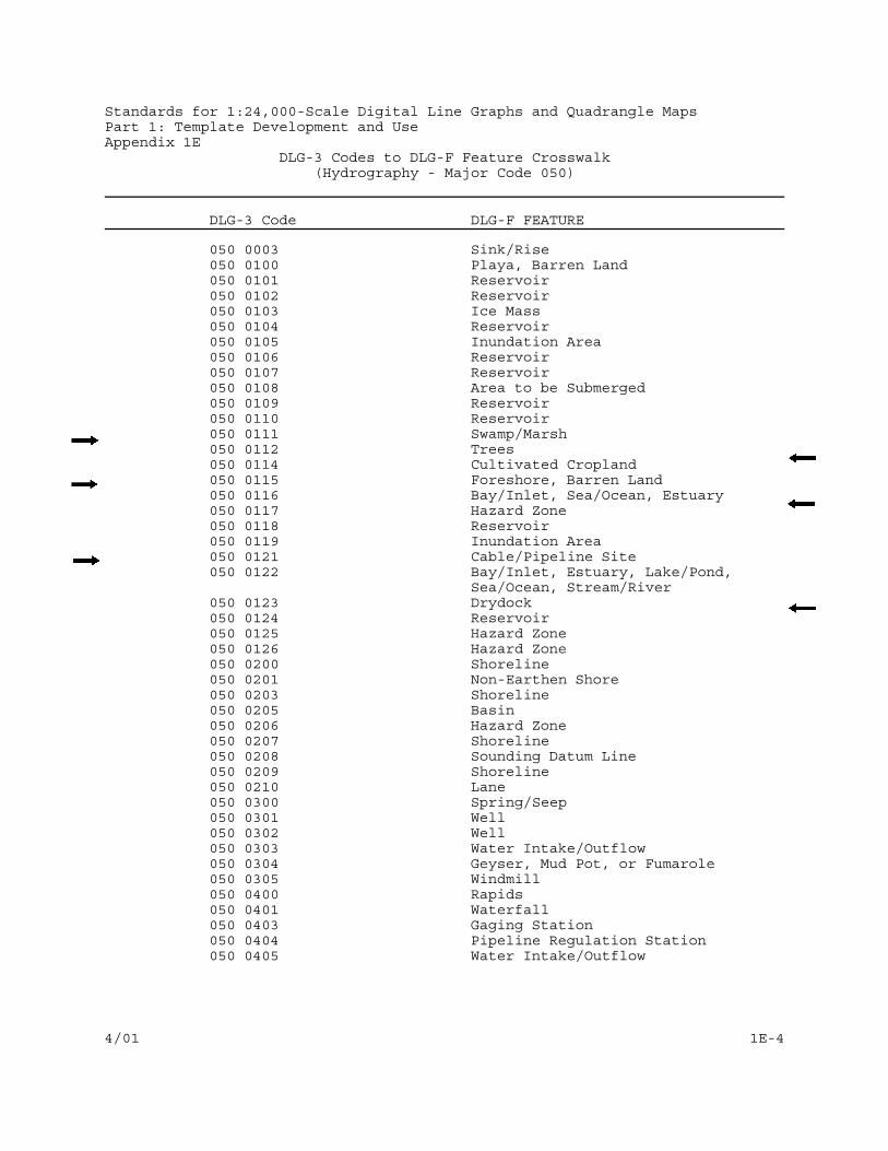
Standards for 1:24,000-Scale Digital Line Graphs and Quadrangle MapsPart 1: Template Development and UseAppendix 1E
DLG-3 Codes to DLG-F Feature Crosswalk(Hydrography - Major Code 050)
DLG-3 Code DLG-F FEATURE
4/01 1E-4
050 0003 Sink/Rise050 0100 Playa, Barren Land050 0101 Reservoir050 0102 Reservoir050 0103 Ice Mass050 0104 Reservoir050 0105 Inundation Area050 0106 Reservoir050 0107 Reservoir050 0108 Area to be Submerged050 0109 Reservoir050 0110 Reservoir050 0111 Swamp/Marsh050 0112 Trees050 0114 Cultivated Cropland050 0115 Foreshore, Barren Land050 0116 Bay/Inlet, Sea/Ocean, Estuary050 0117 Hazard Zone050 0118 Reservoir050 0119 Inundation Area050 0121 Cable/Pipeline Site050 0122 Bay/Inlet, Estuary, Lake/Pond,
Sea/Ocean, Stream/River050 0123 Drydock050 0124 Reservoir050 0125 Hazard Zone050 0126 Hazard Zone050 0200 Shoreline050 0201 Non-Earthen Shore050 0203 Shoreline050 0205 Basin050 0206 Hazard Zone050 0207 Shoreline050 0208 Sounding Datum Line050 0209 Shoreline050 0210 Lane050 0300 Spring/Seep050 0301 Well050 0302 Well050 0303 Water Intake/Outflow050 0304 Geyser, Mud Pot, or Fumarole050 0305 Windmill050 0400 Rapids050 0401 Waterfall050 0403 Gaging Station050 0404 Pipeline Regulation Station050 0405 Water Intake/Outflow

DLG-3 Codes to DLG-F Feature Crosswalk(Hydrography - Major Code 050)
DLG-3 Code DLG-F Feature
Standards for 1:24,000-Scale Digital Line Graphs and Quadrangle MapsPart 1: Template Development and UseAppendix 1E
4/96 1E-5
050 0406 Dam/Weir050 0407 Lock Chamber050 0408 Spillway050 0409 Gate050 0410 Rock, Hazard Zone050 0411 Crevasse Field050 0412 Stream/River, Submerged Stream050 0413 Area of Complex Channels050 0414 Canal/Ditch050 0415 Pipeline, Canal/Ditch050 0416 Flume050 0417 Pipeline050 0418 Pipeline050 0419 Lane050 0420 Wash, Stream/River, Barren Land050 0421 Lake/Pond, Playa050 0422 Reef050 0423 Barren Land050 0424 Special Use Zone050 0425 Fish Ladder050 0426 No F Feature050 0602 Underpass050 0603 Bridge050 0604 Tunnel050 0605 Shoreline050 0606 Shoreline050 0617 Underpass055 ---- Mile Marker050 0630 Barren Land050 0631 Barren Land050 0632 Barren Land050 0633 Barren Land050 0634 Barren Land050 0635 Barren Land050 0636 Barren Land

DLG-3 Codes to DLG-F Feature Crosswalk(Vegetative Surface Cover - Major Code 070)
DLG-3 Code DLG-F Feature
Standards for 1:24,000-Scale Digital Line Graphs and Quadrangle MapsPart 1: Template Development and UseAppendix 1E
4/96 1E-6
070 0101 Trees070 0102 Shrubland070 0103 Cultivated Cropland070 0104 Cultivated Cropland070 0105 Trees

DLG-3 Codes to DLG-F Feature Crosswalk(Non-Vegetative Surface Cover - Major Code 080)
DLG-3 Code DLG-F Feature
Standards for 1:24,000-Scale Digital Line Graphs and Quadrangle MapsPart 1: Template Development and UseAppendix 1E
4/96 1E-7
080 0100 Moraine, Barren Land080 0101 Beach, Barren Land080 0102 Beach, Barren Land080 0104 Barren Land

DLG-3 Codes to DLG-F Feature Crosswalk(Boundaries - Major Code 090)
DLG-3 Code DLG-F Feature
Standards for 1:24,000-Scale Digital Line Graphs and Quadrangle MapsPart 1: Template Development and UseAppendix 1E
4/96 1E-8
090 0001 Boundary Point090 0100 Minor Civil Division090 0101 City090 0103 Reservation090 0104 Reservation090 0105 Reservation, Aquaculture Site090 0106 Reservation090 0107 Reservation090 0108 Reservation090 0110 Reservation090 0111 Reservation090 0129 Reservation090 0130 Reservation090 0131 Reservation, Aquaculture Site090 0132 Reservation090 0133 Reservation090 0134 Reservation090 0135 Locale090 0136 Reservation090 0150 Park, Reservation090 0151 Park, Reservation090 0197 Nation090 0198 Nation090 0199 No E Feature090 0201 Boundary Line090 0202 Boundary Line090 0203 Boundary Line, Survey Line090 0301 Boundary Point091 ---- State/Territory092 ---- County

DLG-3 Codes to DLG-F Feature Crosswalk(Roads and Trails - Major Code 170)
DLG-3 Code DLG-F Feature
Standards for 1:24,000-Scale Digital Line Graphs and Quadrangle MapsPart 1: Template Development and UseAppendix 1E
4/96 1E-9
170 0001 No F Feature170 0002 Tunnel, Tunnel Entrance170 0004 Gate170 0005 Cul-De-Sac170 0007 Draw Span170 0201 Road170 0202 Road170 0203 Road170 0204 Road170 0205 Road170 0206 Road170 0207 Road170 0208 Road170 0209 Road170 0210 Road170 0211 Trail170 0212 Road170 0213 Bridge170 0214 Lane170 0217 Road170 0218 Road170 0219 Road170 0221 Road170 0223 Road170 0222 Road170 0401 Road170 0402 Road170 0403 Gate170 0404 Traffic Inspection Facility, Road170 0405 Road170 0601 Tunnel170 0602 Underpass170 0605 Trail170 0606 Ford170 0607 Underpass

DLG-3 Codes to DLG-F Feature Crosswalk(Railroads - Major Code 180)
DLG-3 Code DLG-F Feature
Standards for 1:24,000-Scale Digital Line Graphs and Quadrangle MapsPart 1: Template Development and UseAppendix 1E
4/96 1E-10
180 0001 No F Feature180 0002 Tunnel, Tunnel Entrance180 0007 Draw Span180 0201 Railway180 0202 Railway, Road180 0204 Railway180 0205 Railway, Cableway180 0207 Lane180 0208 Railway180 0209 Railway Yard180 0400 Building180 0401 Turntable180 0402 Building180 0601 Tunnel180 0602 Underpass180 0605 Underpass180 0611 Bridge

DLG-3 Codes to DLG-F Feature Crosswalk(Pipelines, Transmission Lines, and Miscellaneous Transportation
Features - Major Code 190)
DLG-3 Code DLG-F Feature
Standards for 1:24,000-Scale Digital Line Graphs and Quadrangle MapsPart 1: Template Development and UseAppendix 1E
4/96 1E-11
190 0201 Pipeline190 0202 Transmission Line190 0203 Transmission Line190 0207 Cableway190 0208 Monorail190 0209 Cableway190 0400 Building190 0401 Substation, Building190 0402 Building190 0403 Runway/Apron/Taxiway 190 0404 Helipad190 0405 Launch Facility190 0406 Pipeline Regulation Station190 0408 Building 190 0409 Launching Ramp190 0410 Lane

Standards for 1:24,000-Scale Digital Line Graphs and Quadrangle MapsPart 1: Template Development and UseAppendix 1E
DLG-3 Codes to DLG-F Feature Crosswalk(Hydrography - Major Code 200)
DLG-3 Code DLG-F FEATURE
4/01 1E-12
200 0100 Institutional Site200 0101 Institutional Site200 0102 Institutional Site200 0103 Institutional Site200 0104 Institutional Site200 0105 Mobile Home Park200 0120 Sports Site200 0122 Athletic Field200 0123 Sports Site200 0124 Shopping Center, Building200 0125 Park200 0126 Outdoor Theater200 0127 Sports Site200 0140 Marina200 0150 Built-up Area200 0162 No DLG-F equivalent200 0163 Disposal Site200 0164 Disturbed Surface200 0165 Reservoir200 0181 Holding Pen200 0182 Institutional Site200 0183 Proving Ground200 0184 Sports Site200 0200 Conveyor200 0201 Boardwalk200 0202 Wall200 0203 Wall200 0206 Fence Line200 0209 Pipeline200 0211 Kiln200 0212 Recreational Slide200 0213 Drive-In Theater Screen200 0214 Racetrack200 0301 Historical Monument200 0302 Mine Entrance, Cave Entrance200 0303 Mine Entrance200 0304 Prospect200 0305 Tower200 0306 Chimney200 0307 Well200 0308 Archeological Site/Ruin200 0310 Kiln200 0311 Well200 0314 Tank200 0316 Campground200 0317 Windmill200 0400 Building200 0402 Building200 0403 Building200 0404 Building200 0405 Building

DLG-3 Codes to DLG-F Feature Crosswalk(Manmade Features - Major Code 200)
DLG-3 Code DLG-F Feature
Standards for 1:24,000-Scale Digital Line Graphs and Quadrangle MapsPart 1: Template Development and UseAppendix 1E
4/96 1E-13
200 0406 Building200 0407 Building200 0408 Building200 0409 Building200 0411 Outdoor Theater200 0412 Building200 0413 Building200 0414 Building200 0415 Building200 0416 Building200 0417 Building200 0418 Building200 0419 Building200 0420 Cemetery200 0421 Building200 0422 Building200 0424 Well Field200 0425 Tank200 0426 Offshore Platform200 0427 Disposal Site200 0428 Mine200 0429 Mine200 0430 Mine200 0432 Mine200 0433 Building200 0435 Embankment200 0436 Embankment200 0438 Mine200 0445 Exhibition Ground200 0446 Sports Site200 0447 Holding Pen200 0448 Launching Ramp200 0449 Campground200 0450 Building, Institutional Site200 0451 Reservoir200 0452 Archeological Site/Ruin, Mount200 0453 Rest Site200 0454 Park, Rest Site200 0455 Building200 0456 Building200 0457 Building200 0458 Building200 0459 Building200 0460 Building200 0461 Building200 0462 Building200 0465 Post, Snag/Stump, Hazard Zone200 0466 Pier/Breakwater/Jetty, Wharf200 0467 Wreck, Hazard Zone200 0468 Wreck, Hazard Zone

DLG-3 Codes to DLG-F Feature Crosswalk(Public Land Survey System - Major Code 300)
DLG-3 Code DLG-F Feature
Standards for 1:24,000-Scale Digital Line Graphs and Quadrangle MapsPart 1: Template Development and UseAppendix 1E
4/96 1E-14
300 0001 Survey Corner300 0004 Survey Corner300 0007 Survey Corner300 0008 Survey Corner300 0009 Survey Corner300 0010 Survey Corner300 0012 Survey Corner300 0014 Survey Corner300 0101 Special Survey Area300 0102 Special Survey Area300 0103 Land Grant300 0104 Public Land Survey System Area300 0105 Public Land Survey System Area300 0106 Land Grant300 0108 Public Land Survey System Area300 0110 Public Land Survey System Area300 0111 Special Survey Area300 0112 Special Survey Area300 0113 Special Survey Area300 0114 No F Feature300 0198 No F Feature300 0201 Survey Line300 0202 Survey Line300 0203 Survey Line300 0300 Survey Corner300 0301 Survey Corner