Embed Size (px)
Citation preview
Contents page:
Preface and general safety instructions
Part 1: Operating instructions Cl. 467
1. Product description . . . . . . . . . . . . . . . . . . . . . . . . . . . . 5
2. Designated use . . . . . . . . . . . . . . . . . . . . . . . . . . . . . . 5
3. Sub-classes . . . . . . . . . . . . . . . . . . . . . . . . . . . . . . . . 63.1 Optional Equipment . . . . . . . . . . . . . . . . . . . . . . . . . . . . 6
4. Technical data . . . . . . . . . . . . . . . . . . . . . . . . . . . . . . . 6
5. Operation5.1 Threading the needle thread . . . . . . . . . . . . . . . . . . . . . . . . 95.2 Adjusting needle-thread tension . . . . . . . . . . . . . . . . . . . . . . 95.3 Opening the needle-thread tensioner . . . . . . . . . . . . . . . . . . . 95.4 Winding on the looper thread . . . . . . . . . . . . . . . . . . . . . . . 115.5 Fitting the looper-thread bobbin . . . . . . . . . . . . . . . . . . . . . . 115.6 Adjusting looper-thread tension . . . . . . . . . . . . . . . . . . . . . . 135.7 Fitting and replacing the needle . . . . . . . . . . . . . . . . . . . . . . 135.8 Lifting the sewing feet . . . . . . . . . . . . . . . . . . . . . . . . . . . 155.9 Arresting the sewing feet in the up position . . . . . . . . . . . . . . . 155.10 Adjusting the sewing-foot stroke . . . . . . . . . . . . . . . . . . . . . 155.11 Adjusting the sewing-foot pressure . . . . . . . . . . . . . . . . . . . . 165.12 Adjusting the stitch length . . . . . . . . . . . . . . . . . . . . . . . . . 16
6. Control unit and operating panel6.1 General . . . . . . . . . . . . . . . . . . . . . . . . . . . . . . . . . . . 176.2 Operating-panel keys . . . . . . . . . . . . . . . . . . . . . . . . . . . . 186.3 Changing parameter values . . . . . . . . . . . . . . . . . . . . . . . . 19
7. Sewing . . . . . . . . . . . . . . . . . . . . . . . . . . . . . . . . . . . 21
8. Maintenance . . . . . . . . . . . . . . . . . . . . . . . . . . . . . . . . 238.1 Cleaning and testing . . . . . . . . . . . . . . . . . . . . . . . . . . . . 238.2 Lubrication . . . . . . . . . . . . . . . . . . . . . . . . . . . . . . . . . 27
9. Optional Equipment . . . . . . . . . . . . . . . . . . . . . . . . . . . 289.1 Electropneumatic Seam Bartacking and Sewing Foot Lift (RAP 13-4) 289.1.1 Function . . . . . . . . . . . . . . . . . . . . . . . . . . . . . . . . . . 289.1.2 Keys on the Machine Arm . . . . . . . . . . . . . . . . . . . . . . . . 299.1.3. Sewing . . . . . . . . . . . . . . . . . . . . . . . . . . . . . . . . . . . 30
1. Product description
The DÜRKOPP ADLER 467 is a special sewing machine with a comprehensive rangeof applications.
• Flat-bed double lockstitch sewing machine with underfeed, needle feed andalternating-foot overfeed.
• Sub-classes available with or without thread cutter beneath the needle plate.
• Thread control with one main tensioner.
• Maximum clearance beneath lifted sewing feet 16 mm.
• Stroke of alternating sewing feet with the sewing machine at a halt adjustablebetween 1.5 and 6 mm by press-button and handwheel (adjusting cam).
• Three oil-filling points for manual lubrication of sewing head and shuttle bearing.
• Large, two-part vertical shuttle (to the right of the needle) with bobbin-housing lift.
• A safety coupling prevents the shuttle from disturbance or damage if thread getsinto the shuttle track, blocking the shuttle.
2. Designated use
The 467 is a special sewing machine designed for use with light to medium-heavymaterials. As a rule such materials are fabrics consisting of textile fibres, but they alsoinclude leather. They are used in the clothing, domestic-upholstery andautomobile-upholstery industries.
This special sewing machine can also be used to execute so-called technical seams.However, the operator must carry out an assessment of the possible dangers (withwhich DÜRKOPP ADLER AG would be happy to assist), as such applications arecomparatively unusual and they are potentially of enormous diversity. Depending on theoutcome of this assessment it may be necessary to take special safety precautions.
Generally speaking material processed with this special sewing machine must be dry,its thickness when compressed by the lowered sewing feet must not exceed 10 mm andit must contain no hard objects, since otherwise the operator of the machine would haveto wear protective goggles (which cannot at present be supplied).
The seam is generally executed with textile-fibre sewing threads of dimensions up to11/3 NeB (cotton thread), 11/3 Nm (synthetic thread) or 11/4 Nm (covering yarn). Theuse of any other threads must also be subject to an assessment of the risks involvedand the taking of any necessary safety precautions.
The premises in which this special sewing machine is set up and operated must be dryand well-maintained. If it is to be used in premises which are not dry andwell-maintained, special precautions may be necessary: these must be the subject ofan agreement (see EN 60204-3-1:1990).
As manufacturers of industrial sewing machines we work on the assumption thatpersonnel working on our machines will be at least semi-skilled, so that they can bepresumed to be familiar with all normal operations and with the dangers inherent inthem.
5
3. Sub-classes
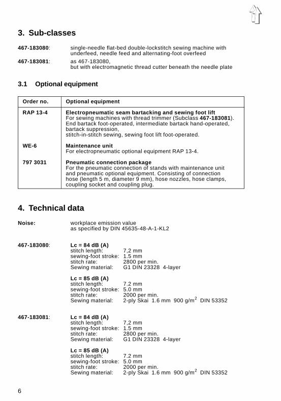
467-183080: single-needle flat-bed double-lockstitch sewing machine withunderfeed, needle feed and alternating-foot overfeed
467-183081: as 467-183080,but with electromagnetic thread cutter beneath the needle plate
3.1 Optional equipment
Order no. Optional equipment
RAP 13-4 Electropneumatic seam bartacking and sewing foot liftFor sewing machines with thread trimmer (Subclass 467-183081).End bartack foot-operated, intermediate bartack hand-operated,bartack suppression,stitch-in-stitch sewing, sewing foot lift foot-operated.
WE-6 Maintenance unitFor electropneumatic optional equipment RAP 13-4.
797 3031 Pneumatic connection packageFor the pneumatic connection of stands with maintenance unitand pneumatic optional equipment. Consisting of connectionhose (length 5 m, diameter 9 mm), hose nozzles, hose clamps,coupling socket and coupling plug.
4. Technical data
Noise: workplace emission valueas specified by DIN 45635-48-A-1-KL2
467-183080: Lc = 84 dB (A)stitch length: 7,2 mmsewing-foot stroke: 1.5 mmstitch rate: 2800 per min.Sewing material: G1 DIN 23328 4-layer
Lc = 85 dB (A)stitch length: 7.2 mmsewing-foot stroke: 5.0 mmstitch rate: 2000 per min.Sewing material: 2-ply Skai 1.6 mm 900 g/m2 DIN 53352
467-183081: Lc = 84 dB (A)stitch length: 7,2 mmsewing-foot stroke: 1.5 mmstitch rate: 2800 per min.Sewing material: G1 DIN 23328 4-layer
Lc = 85 dB (A)stitch length: 7.2 mmsewing-foot stroke: 5.0 mmstitch rate: 2000 per min.Sewing material: 2-ply Skai 1.6 mm 900 g/m2 DIN 53352
6
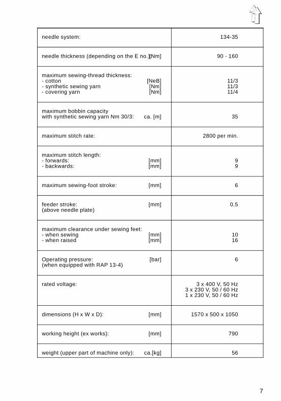
needle system: 134-35
needle thickness (depending on the E no.):[Nm] 90 - 160
maximum sewing-thread thickness:- cotton [NeB] 11/3- synthetic sewing yarn [Nm] 11/3- covering yarn [Nm] 11/4
maximum bobbin capacity with synthetic sewing yarn Nm 30/3: ca. [m] 35
maximum stitch rate: 2800 per min.
maximum stitch length:- forwards: [mm] 9- backwards: [mm] 9
maximum sewing-foot stroke: [mm] 6
feeder stroke: [mm] 0.5(above needle plate)
maximum clearance under sewing feet:- when sewing [mm] 10- when raised [mm] 16
Operating pressure: [bar] 6(when equipped with RAP 13-4)
rated voltage: 3 x 400 V, 50 Hz3 x 230 V, 50 / 60 Hz1 x 230 V, 50 / 60 Hz
dimensions (H x W x D): [mm] 1570 x 500 x 1050
working height (ex works): [mm] 790
weight (upper part of machine only): ca.[kg] 56
7
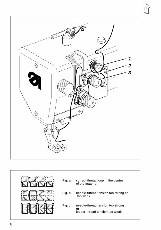
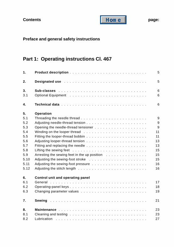
Fig. a: correct thread loop in the centre of the material
Fig. b: needle-thread tension too strong or too weak
Fig. c: needle-thread tension too strongorlooper-thread tension too weak
123
8
5. Operation
5.1 Threading the needle thread
Caution - danger of injuryTurn off the main switch.The needle thread may only be threaded with the sewingmachine at a halt.
– Thread the needle thread as shown in the illustration.
5.2 Adjusting needle-thread tension
Preliminary tension 1On the 467-183081 machine the needle thread needs to be under residual tension forthe thread cutter to function reliably when the main tensioner 3 is open.
The preliminary tension 1 should be set lower than the main tension 3.
– Adjust preliminary tension 1 by rotating the Knurled nut.
– After major changes to preliminary tension 1 the main tension 3 should also beadjusted accordingly.
Main tension 3The main tension 3 should be set as low as possible.The looping of the threads must be in the centre of the material (see fig. a).With thin material excessive thread tension can cause unwanted gathering and threadbreakage.
– Adjust the main tension 3 so that the stitches are uniform.
5.3 Opening the needle-thread tensioner
AutomaticThe main tensioner 3 is opened automatically:
– when the thread is severed (sub-class 467-183081).
ManualThe main tensioner 3 is opened manually:
– when button 2 is pressed.The main tensioner 3 remains open for as long as button 2 is held down.
– when the sewing feet are raised with the knee lever (see chapter 5.8).
– when the sewing feet are arrested in the up position (see chapter 5.9).
9
6 7
4 5
4 8
6 7 5
1 2
3
10
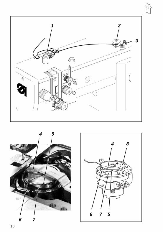
5.4 Winding on the looper thread
Caution - danger of injuryTurn off the main switch.The looper thread may be threaded for winding on onlywhen the sewing machine is switched off.
– When winding on for sewing with no underlay material:arrest the sewing feet in the up position (see chapter 5.9).
– Thread looper thread as shown in the upper illustration.
– Wind about 5 coils of looper thread anti-clockwise onto the bobbin core.
– Place bobbin on bobbin winder 2.
– Swivel bobbin-winder lever 3 against the bobbin.
– Adjust tension 1.The looper thread should be wound on with minimal tension.
– Sew.The bobbin-winder lever 3 terminates the process as soon as the bobbin is full.
5.5 Fitting the looper-thread bobbin
Caution - danger of injuryTurn off the main switch.The looper-thread bobbin may only be changed with thesewing machine at a halt.
Removing empty looper-thread bobbin
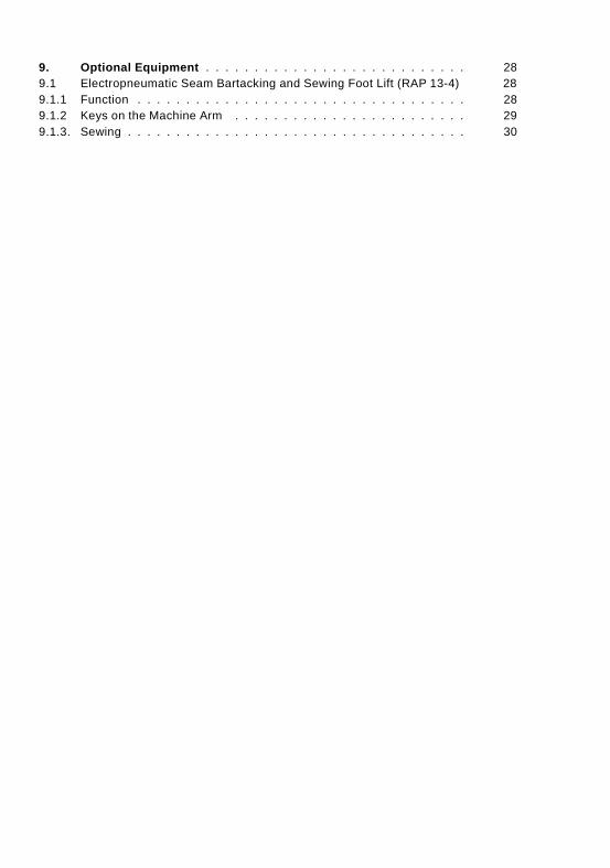
– Press leaf spring down and push right-hand needle-plate slide aside.
– Raise bobbin-housing shutter 4.
– Remove empty looper-thread bobbin.
Threading looper thread
– Place full bobbin 8 in bobbin housing:when the thread is wound off the bobbin must rotate in the direction of the arrow.
– Draw looper thread through slit 5 down to tensioning spring 7.
– Draw looper thread into slit 6.
– Cut looper thread to a length of about 3 cm.
– Close bobbin-housing shutter 4.
– Draw looper thread through the guide of bobbin-housing shutter 4.
– Push needle-plate slide back into place.
11
1
2
3
4
5
12
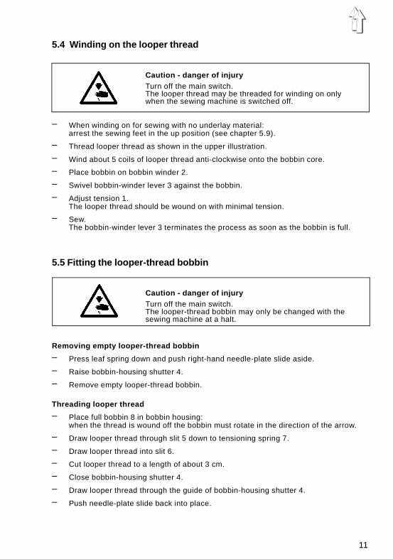
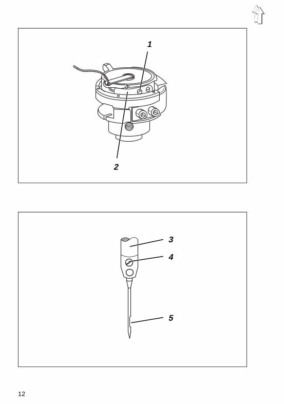
5.6 Adjusting looper-thread tension
Caution - danger of injuryTurn off the main switch.The looper-thread tension may only be adjusted with thesewing machine switched off.
Adjusting tensioning spring 2
– Release right-hand needle-plate slide and push aside.
– Adjust tensioning spring 2 by rotating regulating screw 1.To increase looper-thread tension: = rotate screw 1 clockwise To decrease looper-thread tension= rotate screw 1 anti-clockwise
– Push needle-plate slide back into place.
Note:The conical spring in the bobbin housing has the following functions:
– When the bobbin-housing shutter is open it raises the bobbin slightly for removal.
– It prevents the bobbin from "running on" when the machine halts or if the looperthread is wound off spasmodically.
5.7 Fitting and replacing the needle
Caution - danger of injuryTurn off the main switch.The needle may only be changed with the sewing machineswitched off.
– Rotate the handwheel until the needle bar 3 has reached its uppermost position.
– Undo screw 4.
– Draw the needle downwards out of the needle bar 3.
– Insert a new needle as far as it will go into the hole in the needle bar 3.ImportantWhen viewed from the operating side of the sewing machine the furrow 5 of theneedle must point to the right (see sketch).
– Tighten screw 4.
IMPORTANTWhen fitting a thicker needle the distance of the shuttlefrom the needle must be corrected (see Servicinginstructions).
Failure to comply with the above note may lead to the following errors:
when fitting a thinner needle: faulty stitches, damage to thread when fitting a thicker needle: damage to the shuttle tip and needle
13
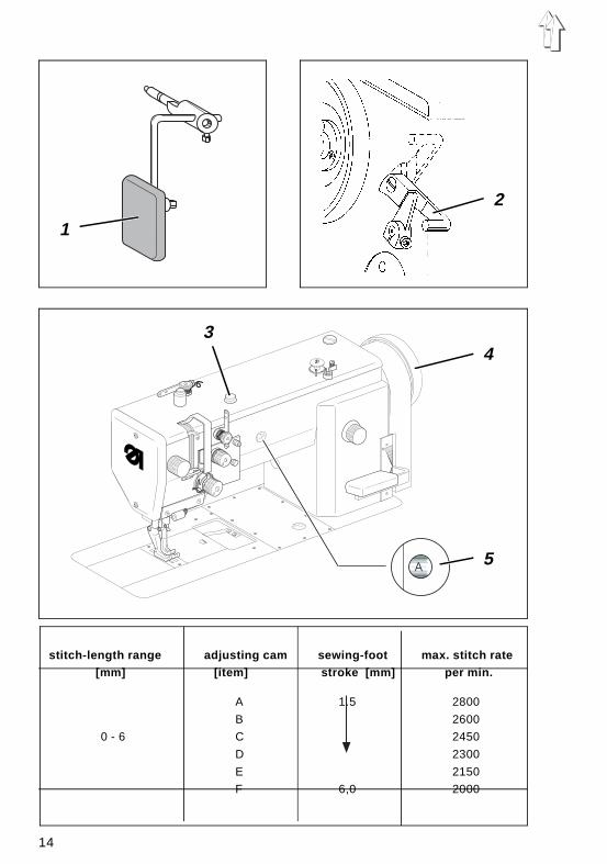
stitch-length range adjusting cam sewing-foot max. stitch rate [mm] [item] stroke [mm] per min.
A 1.5 2800
B 2600
0 - 6 C 2450
D 2300
E 2150
F 6,0 2000
1
2
34
5
14
6 - 9 A - F 1.5 - 6.0 2000
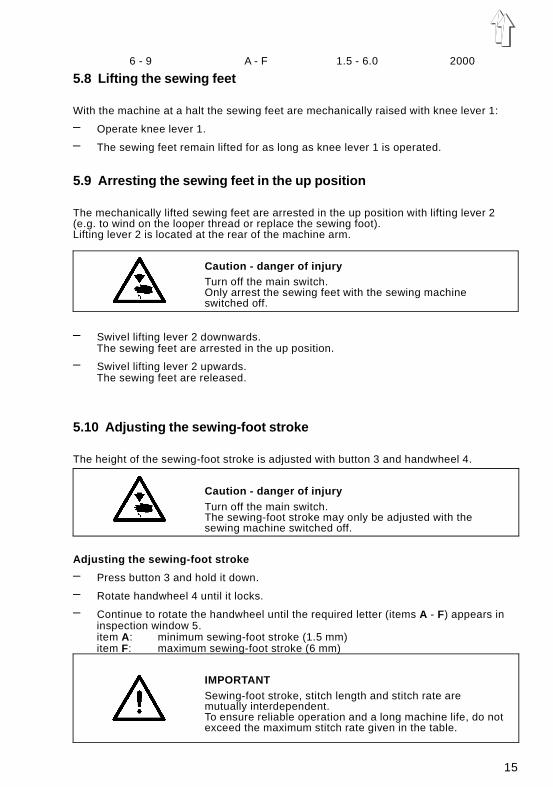
5.8 Lifting the sewing feet
With the machine at a halt the sewing feet are mechanically raised with knee lever 1:
– Operate knee lever 1.
– The sewing feet remain lifted for as long as knee lever 1 is operated.
5.9 Arresting the sewing feet in the up position
The mechanically lifted sewing feet are arrested in the up position with lifting lever 2(e.g. to wind on the looper thread or replace the sewing foot).Lifting lever 2 is located at the rear of the machine arm.
Caution - danger of injuryTurn off the main switch.Only arrest the sewing feet with the sewing machineswitched off.
– Swivel lifting lever 2 downwards.The sewing feet are arrested in the up position.
– Swivel lifting lever 2 upwards.The sewing feet are released.
5.10 Adjusting the sewing-foot stroke
The height of the sewing-foot stroke is adjusted with button 3 and handwheel 4.
Caution - danger of injuryTurn off the main switch.The sewing-foot stroke may only be adjusted with thesewing machine switched off.
Adjusting the sewing-foot stroke
– Press button 3 and hold it down.
– Rotate handwheel 4 until it locks.
– Continue to rotate the handwheel until the required letter (items A - F) appears ininspection window 5.item A: minimum sewing-foot stroke (1.5 mm)item F: maximum sewing-foot stroke (6 mm)
IMPORTANTSewing-foot stroke, stitch length and stitch rate aremutually interdependent.To ensure reliable operation and a long machine life, do notexceed the maximum stitch rate given in the table.
15
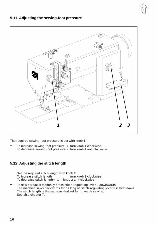
5.11 Adjusting the sewing-foot pressure
The required sewing-foot pressure is set with knob 1.
– To increase sewing-foot pressure = turn knob 1 clockwise To decrease sewing-foot pressure = turn knob 1 anti-clockwise
5.12 Adjusting the stitch length
– Set the required stitch length with knob 2.To increase stitch length = turn knob 2 clockwise To decrease stitch length= turn knob 2 anti-clockwise
– To sew bar tacks manually press stitch-regulating lever 3 downwards.The machine sews backwards for as long as stitch-regulating lever 3 is held down.The stitch length is the same as that set for forwards sewing.See also chapter 7.
1 2 3
16
6. Control unit and operating panel
IMPORTANTThis operating manual covers only the key functions andchange of parameters by the operator.
For a detailed description of the control unit please see themotor manufacturer’s current operating manual (attached).
6.1 General
The operating panel is used to program the control unit and to set the seam functions.
Depending on the nature of the job, sewing may be executed manually or by seamprogramming.
For differing jobs seams can be programmed for which the functions (starting bar tack,ending bar tack, stitch count, thread cutting etc.) and parameter values (stitch rate,seam length, rpm etc.) are individually assigned.
Entry is carried out in programming mode.The parameters and the values assigned are displayed.The seam programs are not lost even when the sewing machine is switched off (batterybuffer).
In order to avoid the inadvertent alteration of pre-set functions, operation is divided intovarious levels (operator, technician, fitter).The operator (seamstress) can program directly.On the other levels access is contingent on the entry of a code number (EFKA).
RESETIf the control unit is hopelessly misadjusted, this function allows the technician to resetall adjusted values to their default (ex-works) settings.
This function is described in the Servicing instructions.
17
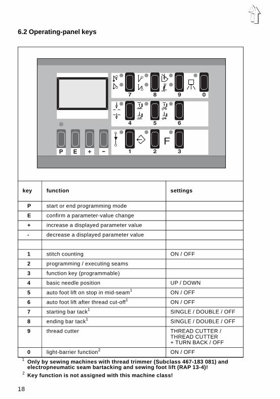
6.2 Operating-panel keys
key function settings
P start or end programming mode
E confirm a parameter-value change
+ increase a displayed parameter value
- decrease a displayed parameter value
1 stitch counting ON / OFF
2 programming / executing seams
3 function key (programmable)
4 basic needle position UP / DOWN
5 auto foot lift on stop in mid-seam1 ON / OFF
6 auto foot lift after thread cut-off1 ON / OFF
7 starting bar tack1 SINGLE / DOUBLE / OFF
8 ending bar tack1 SINGLE / DOUBLE / OFF
9 thread cutter THREAD CUTTER /THREAD CUTTER+ TURN BACK / OFF
0 light-barrier function2 ON / OFF
1 Only by sewing machines with thread trimmer (Subclass 467-183 081) andelectropneumatic seam bartacking and sewing foot lift (RAP 13-4)!
2 Key function is not assigned with this machine class!
18
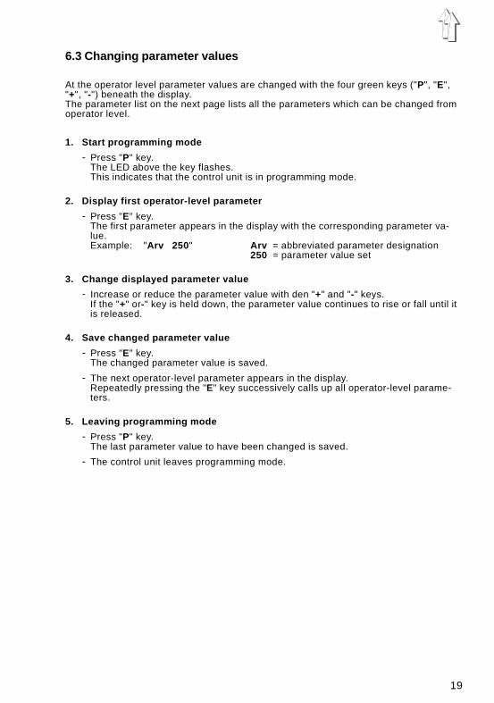
6.3 Changing parameter values
At the operator level parameter values are changed with the four green keys ("P", "E","+", "-") beneath the display.The parameter list on the next page lists all the parameters which can be changed fromoperator level.
1. Start programming mode
- Press "P" key.The LED above the key flashes.This indicates that the control unit is in programming mode.
2. Display first operator-level parameter
- Press "E" key.The first parameter appears in the display with the corresponding parameter va-lue.Example: "Arv 250 " Arv = abbreviated parameter designation
250 = parameter value set
3. Change displayed parameter value
- Increase or reduce the parameter value with den "+" and "-" keys.If the "+" or-" key is held down, the parameter value continues to rise or fall until itis released.
4. Save changed parameter value
- Press "E" key.The changed parameter value is saved.
- The next operator-level parameter appears in the display.Repeatedly pressing the "E" key successively calls up all operator-level parame-ters.
5. Leaving programming mode
- Press "P" key.The last parameter value to have been changed is saved.
- The control unit leaves programming mode.
19
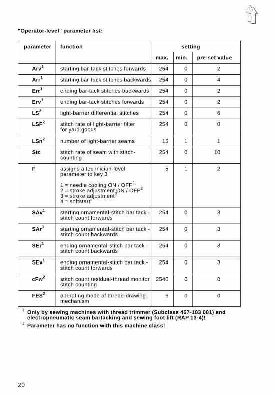
"Operator-level" parameter list:
parameter function setting
max. min. pre-set value
Arv 1 starting bar-tack stitches forwards 254 0 2
Arr 1 starting bar-tack stitches backwards 254 0 4
Err 1 ending bar-tack stitches backwards 254 0 2
Erv 1 ending bar-tack stitches forwards 254 0 2
LS2 light-barrier differential stitches 254 0 6
LSF2 stitch rate of light-barrier filter 254 0 0for yard goods
LSn 2 number of light-barrier seams 15 1 1
Stc stitch rate of seam with stitch- 254 0 10counting
F assigns a technician-level 5 1 2parameter to key 3
1 = needle cooling ON / OFF2
2 = stroke adjustment ON / OFF2
3 = stroke adjustment2
4 = softstart
SAv 1 starting ornamental-stitch bar tack - 254 0 3stitch count forwards
SAr 1 starting ornamental-stitch bar tack - 254 0 3stitch count backwards
SEr1 ending ornamental-stitch bar tack - 254 0 3stitch count backwards
SEv1 ending ornamental-stitch bar tack - 254 0 3stitch count forwards
cFw 2 stitch count residual-thread monitor 2540 0 0stitch counting
FES2 operating mode of thread-drawing 6 0 0mechanism
1 Only by sewing machines with thread trimmer (Subclass 467-183 081) andelectropneumatic seam bartacking and sewing foot lift (RAP 13-4)!
2 Parameter has no function with this machine class!
20
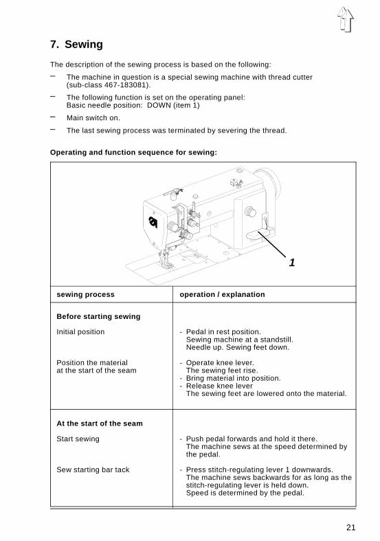
7. Sewing
The description of the sewing process is based on the following:
– The machine in question is a special sewing machine with thread cutter(sub-class 467-183081).
– The following function is set on the operating panel:Basic needle position: DOWN (item 1)
– Main switch on.
– The last sewing process was terminated by severing the thread.
Operating and function sequence for sewing:
sewing process operation / explanation
Before starting sewing
Initial position
Position the material at the start of the seam
- Pedal in rest position.Sewing machine at a standstill.Needle up. Sewing feet down.
- Operate knee lever.The sewing feet rise.
- Bring material into position.- Release knee lever
The sewing feet are lowered onto the material.
At the start of the seam
Start sewing
Sew starting bar tack
- Push pedal forwards and hold it there.The machine sews at the speed determined bythe pedal.
- Press stitch-regulating lever 1 downwards.The machine sews backwards for as long as thestitch-regulating lever is held down.Speed is determined by the pedal.
1
21
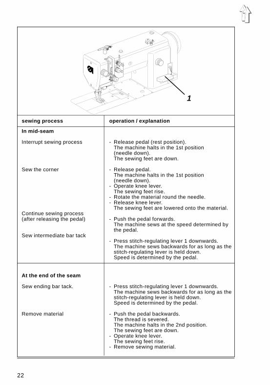
sewing process operation / explanation
In mid-seam
Interrupt sewing process
Sew the corner
Continue sewing process (after releasing the pedal)
Sew intermediate bar tack
- Release pedal (rest position).The machine halts in the 1st position(needle down).The sewing feet are down.
- Release pedal.The machine halts in the 1st position(needle down).
- Operate knee lever.The sewing feet rise.
- Rotate the material round the needle.- Release knee lever.
The sewing feet are lowered onto the material.
- Push the pedal forwards.The machine sews at the speed determined bythe pedal.
- Press stitch-regulating lever 1 downwards.The machine sews backwards for as long as thestitch-regulating lever is held down.Speed is determined by the pedal.
At the end of the seam
Sew ending bar tack.
Remove material
- Press stitch-regulating lever 1 downwards.The machine sews backwards for as long as thestitch-regulating lever is held down.Speed is determined by the pedal.
- Push the pedal backwards.The thread is severed.The machine halts in the 2nd position.The sewing feet are down.
- Operate knee lever.The sewing feet rise.
- Remove sewing material.
1
22
8. Maintenance
Caution - danger of injuryTurn off the main switch.Maintenance of the sewing machine may only be carriedout when it is switched off.
Maintenance work must be carried out no less frequently than at the intervals given inthe tables (see "operating hours" column).
Maintenance intervals may need to be shorter when processing heavy-sheddingmaterials.
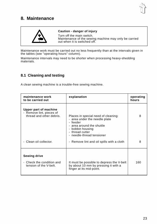
8.1 Cleaning and testing
A clean sewing machine is a trouble-free sewing machine.
maintenance work explanation operatingto be carried out hours
Upper part of machine- Remove lint, pieces of
thread and other debris.
- Clean oil collector.
Places in special need of cleaning:- area under the needle plate- feeder- area around the shuttle- bobbin housing- thread cutter- needle-thread tensioner
- Remove lint and oil spills with a cloth
8
8
Sewing drive
- Check the condition andtension of the V-belt.
It must be possible to depress the V-belt by about 10 mm by pressing it with afinger at its mid-point.
160
23
2
46
8
10
1
2
3
24
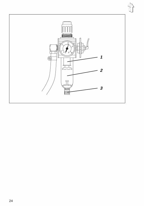
Compressed air maintenance unit (optional equipment)If the special sewing machine is equipped with the compressed air maintenance unitWE-6, the maintenance work listed in the table below is also to be conducted.
Required Remarks Operatingmaintenance work hours
Compressed airmaintenance unit
- Check the water level inthe pressure regulator.
- Clean the filter insert.
The water level should not climb to thefilter insert 1.- After screwing in the drain screw 3,blow the water out of the waterseparator2 under pressure.
Note:The water separator 2 is equipped with asemi-automatic condensation drain.When falling below a certain pressure,the condensation is automaticallydrained.
Dirt and condensation are removedthrough filter insert 1.- Separate the machine from thecompressed air supply.- Screw in the drain screw 3.
The pneumatic system of themachine must be pressure-free.
- Screw water separator 2 off.- Screw filter insert 1 off
Wash out the filter case and filterinsert with naptha (nosolvents! ) and blow out clean.
- Reassemble the maintenance unit againand connect.
40
500
25
4
2
3
1
26
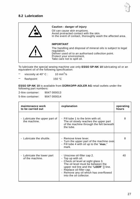
8.2 Lubrication
Caution - danger of injuryOil can cause skin eruptions.Avoid protracted contact with the skin.In the event of contact, thoroughly wash the affected area.
IMPORTANTThe handling and disposal of mineral oils is subject to legalregulation.Deliver used oil to an authorised collection point.Protect your environment.Take care not to spill oil.
To lubricate the special sewing machine use only ESSO SP-NK 10 lubricating oil or anequivalent oil of the following specification:
– viscosity at 40° C : 10 mm2/s
– flashpoint: 150 °C
ESSO SP-NK 10 is available from DÜRKOPP-ADLER AG retail outlets under thefollowing part numbers:
2-litre container: 9047 000013
5-litre container: 9047 000014
maintenance work explanation operatingto be carried out hours
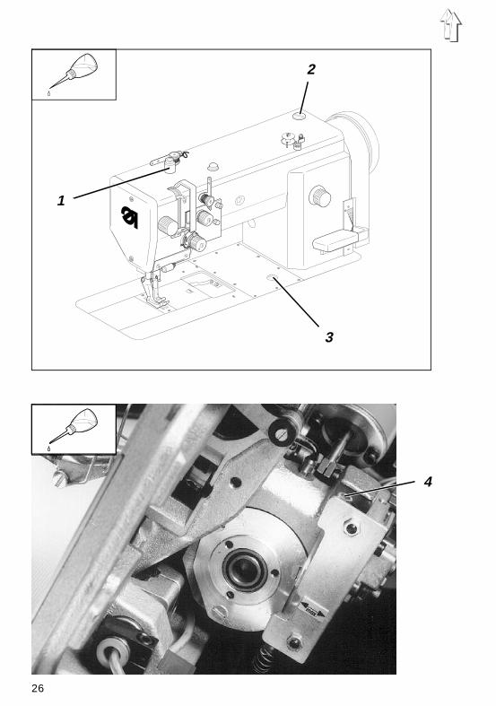
- Lubricate the upper part ofthe machine.
- Fill tube 1 to the brim with oil.The oil slowly reaches the upper partof the machine through the felt beneaththe tube.
8
- Lubricate the shuttle. - Remove knee lever.- Turn the upper part of the machine over.- Fill tube 4 with oil up to the "max. "
mark.
8
- Lubricate the lower partof the machine.
- Unscrew oil-filler cap 2.- Top up with oil.- Check oil level at sight glass 3.
The oil level must be between theupper red line and the "LEER" [] line.
- Replace oil-filler cap.- Remove any oil which has overflowed
into the oil collector.
40
27
9. Optional Equipment
9.1 Electropneumatic Seam Bartacking and Sewing Foot Lift (RAP 13-4)
The electropneumatic seam bartacking and sewing foot lift (RAP 13-4) is only availablefor special sewing machines with thread trimmer (Subclass 467-183 081).It makes possible the following supplementary functions:
– Beginning and end bartack sewing, foot-operated (via pedal)
– Bartack suppression
– Stitch-in-stitch sewing (fancy bartacking)
– Intermediate bartack sewing, hand-operated (via key on the machine arm)
– Sewing foot lift, foot-operated (via pedal)
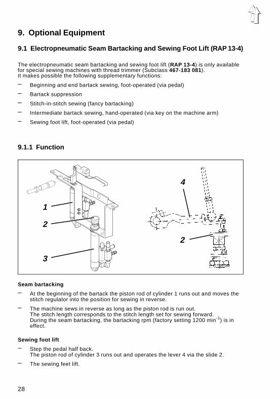
9.1.1 Function
Seam bartacking
– At the beginning of the bartack the piston rod of cylinder 1 runs out and moves thestitch regulator into the position for sewing in reverse.
– The machine sews in reverse as long as the piston rod is run out.The stitch length corresponds to the stitch length set for sewing forward.During the seam bartacking, the bartacking rpm (factory setting 1200 min-1) is ineffect.
Sewing foot lift
– Step the pedal half back.The piston rod of cylinder 3 runs out and operates the lever 4 via the slide 2.
– The sewing feet lift.
1
2
3
2
4
28
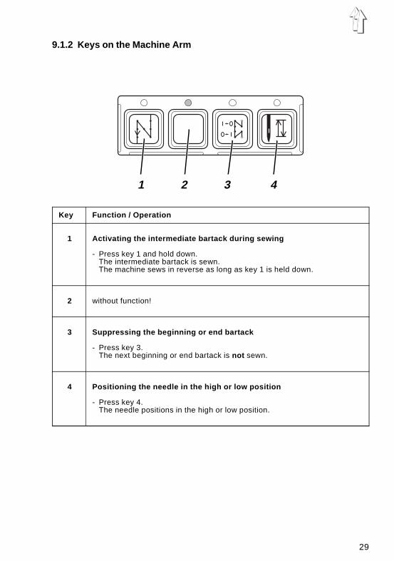
9.1.2 Keys on the Machine Arm
Key Function / Operation
1 Activating the intermediate bartack during sewing
- Press key 1 and hold down.The intermediate bartack is sewn.The machine sews in reverse as long as key 1 is held down.
2 without function!
3 Suppressing the beginning or end bartack
- Press key 3.The next beginning or end bartack is not sewn.
4 Positioning the needle in the high or low position
- Press key 4.The needle positions in the high or low position.
1 2 3 4
29
9.1.3 Sewing
In the description of the sewing, the following preconditions are assumed:
– Special sewing machine with thread trimmer (Subclass 467-183081) andelectropneumatic seam bartacking and sewing foot lift (RAP 13-4).
– The following functions are set on the control panel:
Beginning and end bartack: ONSewing foot position before and after trimming: DOWNNeedle position before trimming: DOWN (position 1)
– The last sewing sequence was completed with end bartack and thread trimming.
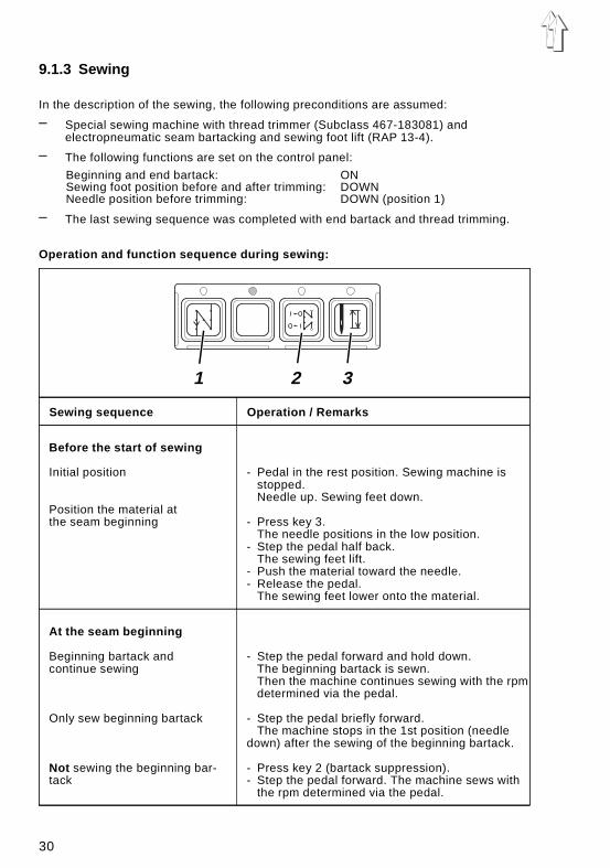
Operation and function sequence during sewing:
Sewing sequence Operation / Remarks
Before the start of sewing
Initial position
Position the material at the seam beginning
- Pedal in the rest position. Sewing machine isstopped.Needle up. Sewing feet down.
- Press key 3.The needle positions in the low position.
- Step the pedal half back.The sewing feet lift.
- Push the material toward the needle.- Release the pedal.
The sewing feet lower onto the material.
At the seam beginning
Beginning bartack and continue sewing
Only sew beginning bartack
Not sewing the beginning bar-tack
- Step the pedal forward and hold down.The beginning bartack is sewn.Then the machine continues sewing with the rpmdetermined via the pedal.
- Step the pedal briefly forward.The machine stops in the 1st position (needle
down) after the sewing of the beginning bartack.
- Press key 2 (bartack suppression).- Step the pedal forward. The machine sews with
the rpm determined via the pedal.
1 2 3
30
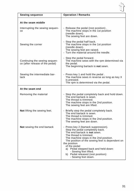
Sewing sequence Operation / Remarks
At the seam middle
Interrupting the sewing sequen-ce
Sewing the corner
Continuing the sewing sequen-ce (after release of the pedal)
Sewing the intermediate bar-tack
- Release the pedal (rest position) .The machine stops in the 1st position(needle down).The sewing feet are down.
- Step the pedal half back.The machine stops in the 1st position(needle down).The sewing feet are raised.
- Turn the material around the needle.
- Step the pedal forward.The machine sews with the rpm determined viathe pedal.The beginning bartack is not sewn.
- Press key 1 and hold the pedal .The machine sews in reverse as long as key Xis pressed.The rpm is determined via the pedal.
At the seam end
Removing the material
Not lifting the sewing feet.
Not sewing the end bartack
- Step the pedal completely back and hold down.The end bartack is sewn.The thread is trimmed.The machine stops in the 2nd position.The sewing feet are lifted.
- Briefly step the pedal completely back.The end bartack is sewn.The thread is trimmed.The machine stops in the 2nd position.The sewing feet are down.
- Press key 2 (bartack suppression).Step the pedal completely back.The end bartack is not sewn.The thread is trimmed.The machine stops in the 2nd position.The position of the sewing feet is dependent on
the positionof the pedal:a) Pedal stepped back and held down:
- Sewing feet lifted.b) Pedal released (rest position):
- Sewing feet down.
31


![887-M - duerkopp-adler.com · Standard [mm] [mm] [mm] max. [min-1] max. [mm] [mm] L 70 – 80 80 134 LR 1,2 1,5 4 2500 0,6 35 L 70 – 80 80 134 LR 1,6 1,5 4 2500 0,6 35](https://img.pdfslide.us/doc/110x75/5d46bfd988c99304028b645a/887-m-duerkopp-adlercom-standard-mm-mm-mm-max-min-1-max-mm-mm.jpg)