Embed Size (px)
Citation preview
Part 1Major Concepts
• Hardware inside the PC
• 5 Elements of a computer
• POST
• Disk boot
• Interrupts
• Plug and Play
Hardware Inside the PC
• Power Supply
• Case
• Removable Drive
• CD-ROM Drive
• Tape Drive
• Hard Drive
• Floppy Drive
Hardware Inside the PC
• IDE Controllers
• AGP Expansion Slot
• PCI Expansion Slot
• Video Card
• Sound Card
• RAM
• Real-Time Clock
Hardware Inside the PC
• CMOS [Complementary Metal-Oxide Semiconductor]
• BIOS [Basic Input-Output System
• CMOS Battery
• Microprocessor
• Heat Sink
• Fan
Hardware Inside the PC
• USB ports
• Mouse Port
• Keyboard
• Parallel Port
• Serial Ports
• Sound Card Connections
• Modem
5 Elements of a Computer
• Input
• Output
• Memory
• CPU
• Storage
Input/Output
• Sound Card– Speaker output– Microphone & line inputs
• Modem (MOdulator/DEModulator)
• Ports (USB, Parallel, Serial, SCSI)
Input
• Keyboard
• Mouse/Trackball/Touchpad/Wireless/programmable/pointing/optical– Originated by Xerox Palo Alto
• Touch screens
Output
• Video Card (AGP)– Powerful computer in its own right
• Display (monitor)– Resolution– Refresh Rate– Bandwidth
Electronic Memory
• L1 Cache (on microprocessor chip)
• L2 Cache (on motherboard)
• RAM (on motherboard or daughter board)
CPU: Control and ALU
• Microprocessor
• Real-time clock
• BIOS
• CMOS
• IDE Controller
• SCSI Controller
• USB Controller
Power-On Self-Test
• Boot (Boot Strapping)– Steps computer takes to get from your pushing “on”
button to when the computer is operational
• First Step: Power On Self Test (POST)– Purpose: Computer tests itself to ensure that basic
processing unit and connected devices are alive and well
– Test Result• Pass: single short beep• Failure: different combinations of beeping (including no beep
at all), displays messages, if possible
How Does POST work?
• When Power Is Turned On, Electrical Signal Is Sent to CPU Signaling It to Reset– Clears old data, initializes counters (registers)
– Sets program counter to pre-defined address in memory (F000)
– Memory location referenced is in Read Only Memory (ROM) of PC’s Basic Input/Output System (BIOS)
• ROM stays the same, even when we turn off the power
• Instructions define steps CPU should perform to complete self test

Self Test Steps
• CPU Checks Itself (e.g., adds some numbers, checks results)
• Sends Electrical Signals Over Bus to See If All Components Connected to Bus Are Functioning
• Check System Timer (Real-time Clock) • Check Out memory on Video Card
– Locate card, execute video card POST– If passes, link video card to CPU’s BIOS– If all goes well, display text/graphics
Self Test
• Check Out RAM (volatile memory)– Write data to each chip– Read stored data: is it what was written?– Detect how much memory is available

Self Test
• Establish What Disk Drives Are Available
• Verify Keyboard, Have Any Keys Been Pressed?
• Now That Post Is Complete…– Components are functioning properly
– Have located disk drives
Self Test
• Check Out Remaining Components– See if component contains own BIOS code
– If so, execute startup code, link to BIOS
– See if component supports Plug and Play• execute Plug and Play instructions to distribute system
resources
• Compare Component Inventory With “Saved” List– Stored in “CMOS” chip
– If different given choice: is this new list correct?
Disk Boot
• Task– Objective: load operating system, which includes
software to access disks into memory– Problem: how do I load from a disk the software that tells
me how to use a disk if I don’t know how to access the disk in the first place?
• Key players– BIOS (in EPROM) (will link to operating system)– CPU (brains)– Disk drive, contains disk operating software– RAM (final resting place for software)
Disk Boot 1
• BIOS checks floppy disk drive. If present, checks predefined location on floppy for disk operating system files (IO.SYS and MSDOS.SYS)– If not present in floppy, checks hard drive– If not present on hard drive, generate error
message– Order of reading devices can be changed in
BIOS setup
Disk Boot 2
• Boot program reads first sector of disk (cylinder 0, head 0, sector 1) (512 bytes): Master Boot Record (MBR)– MBR is a miniprogram that locates bootable
partition of the disk– BIOS transfers control to MBR– MBR locates DOS boot record (DBR), also a
mini-program
Disk Boot 3
• DBR attempts to load “hidden” file IO.sys into RAM– If OK, DBR transfers control to SYSINIT, a
program within IO.sys– At this time boot record is no longer needed
and can be erased from RAM.
Disk Boot 4
• SYSINIT loads MSDOS.sys into RAM– File management
– How to execute programs
– Interact with hardware
• SYSINIT locates CONFIG.SYS (at root directory)– User defined
– Let’s user tailor operating system
– Loads certain device drivers
Interrupt Handling
• When an “Event” Occurs, a Hardware Signal Is First Sent to the Interrupt Controller Chip That Detects and Interprets the Interrupt
• Interrupt Controller Chip Notifies CPU That Interrupt Has Occurred
• Since the CPU Was Doing Other Things, the Processor Saves Its Current State So That It Can Resume That Task Later (Pushes Data Onto the Stack)
What is Plug and Play? 1
• So what’s the problem?– Each PC Contains a Number of Components That Need
to Work Together
– Each Component May Need to Have Its Own:• Interrupt ID
• RAM that only it writes to (DMA)
• Input/Output address (e.g., floppy drive vs. hard drive)
• ROM address (where its own BIOS will go)
• RAM buffer address (how data is passed to/from this component)
What is P&P? 2
– This Cooperation Depends on the Exact Configuration of Components
– Each Time a Component Is Added or Taken Away, the Configuration Must Be Changed
– Plug and Play Is a Standard Which Allows Your Computer to Perform This Task “Automatically”, Letting You Use You New Components Without Time or Error Potential of Performing Your Own Installation
How Does Plug and Play Work? 1
• Plug and Play Compatible BIOS Locates All Potential Components (Plug and Play Compatible)
• Each component contains a unique identifier as part of its Read Only Memory (non-volatile memory)
• Each component defines what resources it needs and what range of resources it will accept
• BIOS transfers control to operating system
How Does P&P Work? 2
• Windows Configuration Manager Creates Enumerators (Interface Programs Between Operating System and Devices Themselves) Based Upon Located Interfaces– ISA enumerator– SCSI enumerator– Port enumerator
How Does P&P Work? 3
• Enumerators Consolidate Information for All Components Using a Given Interface and Provide This to the Configuration Manager
• Configuration Manager Assigns Actual Resources (e.g., Interrupt IDs), Avoiding Conflicts. Each Component Stores These Assignments Within Its Own Hardware So That It Knows How It Will Be Used
• OS Locates Driver for All Components: If Not Found, Asks User to Install It
Part 2Major Concepts
• How programming languages work, different programming languages
• Windows multi-tasking• Manipulators of data• Bitmapped graphics, compression, vector graphics• Resolution• Computer security definitions• Viruses, anti-virus software
How Programming Languages Work
• Software is created using different computer programming languages that provide instructions for telling computers what to do
• Unlike the English language, which is less than precise, computer language is more exacting and limited
• Different programming languages for different types of computers and tasks– Usually described as low-level or high level
Different Programming Languages
• Low-level versus high-level languages– The more a computer language represents
English, the higher its level• Low-level- ‘machine’ language – a series of codes
represented by 1s and 0s• Communicate directly with the PCs processor
– Assembly Language• Slightly higher than low-level language, uses simple
command words to supply step-by-step instructions for the CPU to carry out
Different Programming Languages - 2
• High-level languages allow programmers to write in words and terms that more closley parallel english– Java– C, C++– XML
• Highest level languages– BASIC – [Beginners All-Purppose Symbolic Instruction
Code]– Visual Basic key many key words and phrases that execute
specific commands within the program when it is compiled [run]
Multitasking Under OS Control
• Running several application programs at the same time– Doing a web search while typing in your
homework on your word processor
• What problems does this create?– Only 1 CPU (processor)– Memory
• Use must be coordinated• May run out of RAM in MS Windows
Windows Multitasking (Memory)
• Each application is assigned a block of RAM for its exclusive use
• As allocated RAM fills up, OS swaps out unused “pages” of RAM to virtual memory on disk– If swapped-out pages are needed later, they
must be swapped back into RAM, from slower virtual memory
Windows Multitasking (CPU)
• Each program is given a very short slice of time– Not interrupt driven
• When time is up – CPU internal registers used by the application
are saved– CPU internal registers used by the other
application are restored

Windows Multitasking (Peripherals)
– If application program wants to use a peripheral, it queries the OS
– If free, OS connects application to peripheral (e.g., prints document)
– If not free, OS rejects request, or, e.g., queues file to print and prints when free

Manipulators of Data (1)
• Database managers– Address list – Digital juke boxes
• Word processing– Including desktop publishing– html editors
Manipulators of Data (2)
• Number crunchers– Spreadsheets– Financial packages
• Graphics– Drafting programs (CAD)– Paint programs– Photo editing
Manipulators of Data (3)
• Multimedia– Combines pictures, music, spoken words
• Communications software– E-commerce, broadcasting, email– Encryption
• Utilities– Virus checkers– Compression
Bitmapped Graphics Files
• File starts with information– Which bitmapped graphics format it is in
• .BMP, .PCX, .TIF, .JPG
• “Magic” number
– The height and width of the picture in pixels– The palette
• Number and range of colors which can be used in the image
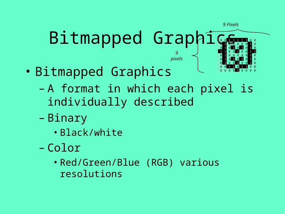
Bitmapped Graphics
• Bitmapped Graphics– A format in which each pixel is individually
described – Binary
• Black/white
– Color• Red/Green/Blue (RGB) various resolutions
0 0 1 1 1 1 1 0 00 1 0 0 0 0 0 1 00 1 0 1 0 1 0 1 01 1 0 0 1 0 0 1 10 1 0 0 0 0 0 1 00 1 0 1 0 1 0 1 00 1 0 0 1 0 0 1 00 0 1 1 0 1 1 0 00 0 0 0 1 0 0 0 0
9 Pixels
9pixels
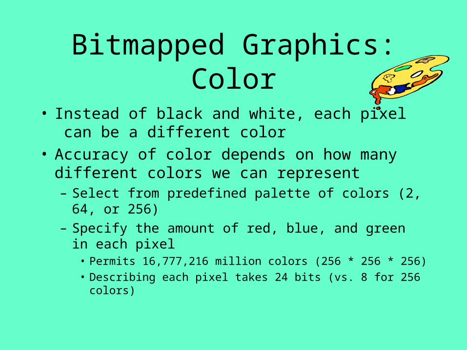
Bitmapped Graphics: Color
• Instead of black and white, each pixel can be a different color
• Accuracy of color depends on how many different colors we can represent– Select from predefined palette of colors (2, 64, or 256)
– Specify the amount of red, blue, and green in each pixel• Permits 16,777,216 million colors (256 * 256 * 256)
• Describing each pixel takes 24 bits (vs. 8 for 256 colors)
Compression
• Describing all these pixels in so many colors can take up a lot of space– More file space– More RAM to display– More time to see web page– More time to ftp data over communications link
Compression (1)
• To reduce storage requirements, use data compression techniques– Lossless
• Reduce data quantity without loss of information• Scientific uses, e.g., space imagery from Mars
– Lossy• Reduce data quantity, but loss of quality• JPEG, reduce quantity with minimal loss of quality
Compression (2)
• Detect presence of patterns within data– Observation: consecutive pixels are often same color
– Use run-length encoding (RLE)• Check first bit of key byte
– if 1, next 7 bits define how many subsequent bytes will describe individual pixels
– if 0, next 7 bits define how many subsequent bytes will have the identical color value
– RLE great when consecutive pixels are same, can actually require more storage if all pixels are different
Displaying Bitmapped Graphics
• Video Graphics Adapter Card – Stores image in video memory– Controls position of beam on screen– Uses digital to analog (D/A) converter chip to convert digital representation of hue,
saturation, and intensity (HSI) into electrical signal fed to monitor to write each pixel
• Screen consists of red, green, and blue phosphors which “phosphoresce” at varying intensities to create color.
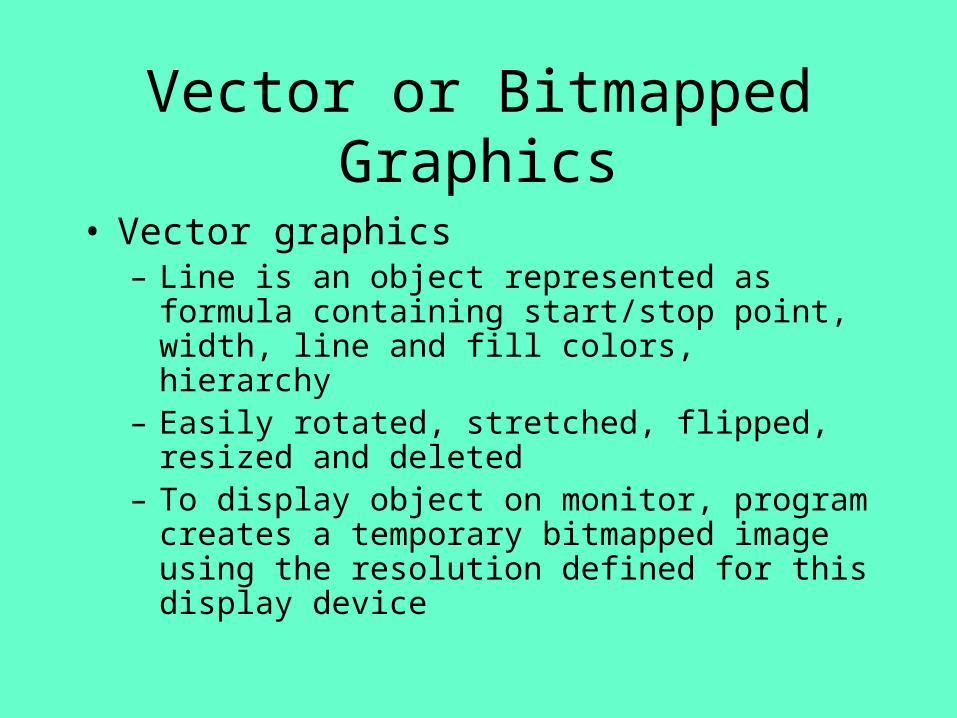
Vector or Bitmapped Graphics
• Vector graphics– Line is an object represented as formula containing
start/stop point, width, line and fill colors, hierarchy– Easily rotated, stretched, flipped, resized and deleted– To display object on monitor, program creates a
temporary bitmapped image using the resolution defined for this display device

Vector or Bitmapped Graphics
• Consider drawing a red line via graphics creation software
• Paint (bit mapped graphics) – Fixed number of pixels form the entire line– Not easily enlarged or reduced
Creating graceful curves is easy with Draw programs: can control exactly the location and degree of curvature

Resolution
• We can also control how many pixels we use to represent the picture
LineArt1,000
Gray Scale7,000
72 DPIColor
21,000
150 DPIColor
88,000
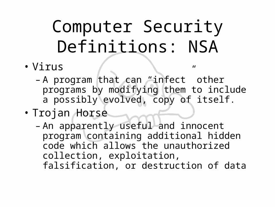
Computer Security Definitions: NSA
• Virus– A program that can “infect” other programs by
modifying them to include a possibly evolved, copy of itself.
• Trojan Horse– An apparently useful and innocent program
containing additional hidden code which allows the unauthorized collection, exploitation, falsification, or destruction of data
Definitions: NSA• Tinkerbell Program
– A monitoring program used to scan incoming network connections and generate alerts when calls are received from particular sites, or when logins are attempted using certain ID’s
• Back door– A hole in the security of a computer system
deliberately left in place by designers or maintainers. Also trapdoor.
Definitions: NSA
• Hacking– Unauthorized use, or attempts to circumvent or
bypass the security mechanisms of an information system or network
• Letterbomb– A piece of email containing live data intended
to do malicious things to the recipient’s machine or terminal
Typical Virus Approach (1)
• Replication to infect others– Virus copies itself into the beginning of
programs that a user typically runs– Virus copies itself to disk boot record
• Camouflage to avoid detection– Change itself so that detection software cannot
identify it by a unique signature – Distort file size information so that additional
virus code is not detected
Typical Virus Approach (2)
• Event watching– Executing in background, virus continually
checks for a specific event to occur (e.g., specific date)
• Delivery– Display message, delete files, corrupt files, etc.
How does a computer get infected?
• Embedded in master boot record of stranger disk
• Embedded in new executable software
• Embedded in a mail message– Typically a program within mail message– Can also be a macro within a data file such as
MS Word document

Antivirus Actions
• Check all locations where virus may reside– Master boot record– Program files– Macro code
• Signature Scanners– Check for exact match of program instructions
Antivirus Actions
• Heuristic Detectors focus on typical behavior of viruses
• Memory resident– Continually running on computer – Intercedes when “unsafe” operation
• Downloading files from Internet
• Copying files
• Another program tries to stay resident in memory
Part 3Major Concepts
• Transistors
• RAM
• Logic Gates
How a Transistor Works
• Thousands of transistors are connected on a single slice of Silicon
• The slice is embedded in a piece of plastic or ceramic with the ends of the circuitry attached to metal leads that reach out to connect to other parts of the computer circuit board
• The leads carry signals to the chip and send signals form the chip to other components
How a Transistor Works
• The transistor is the basic building block from which all microchips are built
• It can only create binary information, a 1 if current passes through it, a 0 if current does not
How a Transistor Works
• PCs based on the the first Intel 8088 and 80286 processors were 16 bit PCs
• They could work with numbers of up to 16 bits in length, or a decimal number of 65,535
• Current PCs are 32 bit capable and work with numbers that are 32 bits wide, the equivalent of 4,294,967,295
How a Transistor Works• Transistors can just as easily represent a true or
false condition• Transistors in various combinations form Logic
Gates• Logic Gates are combined into arrays to form Half
Adders• Half Adders are combined to Full Adders• More than 260 transistors are needed to create a
full adder capable of handling mathematical operations for 16 bit numbers

How a Transistor Works
• A small positive charge is sent down an aluminum lead that runs inside the transistor
• The charge spreads to a layer of conductive polysilicon buried in the middle of non-conductive silicon dioxide– Silicon Dioxide is the main component of sand
How a Transistor Works
• The positive charge on the aluminum attracts negatively charged electrons out of the base of the transistor made of p-silicon creating a vacuum
• On one side of the transistor exists a Source lead that fills the vacuum created by the rush of negatively charged particles with additional negatively charged particles
• The electrons from the source also flow toward a similar conductive lead called the Drain
How a Transistor Works
• The rush of electrons completes an electrical circuit turning the transistor on which represents a ‘1’ bit.
• If a negative charge is applied to the polysilicon, the negatively charged electrons will repel each other and the transistor will remain off and represent a ‘0’ bit
How RAM Works• Before a PC can do anything it must move data from
disk to RAM• Data contained in documents must also be stored in
RAM if only for a fraction of a second before it moves to the processor for computation
• Every PC is a collection of switches representing a ‘1’ or a ‘0’ which represent every piece of data that runs on your PC
• RAM is blank upon energizing the PC, becomes filled with ‘1’s and ‘0’s when you turn off your PC, the contents of RAM is lost
How data is Written to RAM
• Think of the inside of your PCs RAM like a collection of switches connected by microscopic electrical circuits called Address Lines
• Software, in combination with the OS is continually sending tiny bursts of electrical current along Address Lines
• Each Address Line identifies locations of spots where data can be stored
How Data is Written to RAM
• The electrical pulse turns on or closes a transistor that’s connected to a Data Line at each memory location where data can be stored
• While transistors are turned on, software continuously sends bursts of electricity along selected data lines
• Each burst represents a 1 bit to a transistor
How Data is Written to RAM
• Where a transistor is turned on, the burst of electricity serves to charge a capacitor which stores electricity and keeps the 1 bit stored in the transistor
• Each charged capacitor represents a 1 bit• Each uncharged capacitor indicates a 0 bit• Capacitors will eventually lose their charge
if not refreshed regularly
How Data is Read From RAM• When software wants to read data from RAM, another
electrical pulse is sent along the address line, closing the transistors connected to it
• At each address line where there is a charged capacitor, the capacitor will discharge via the circuit created by the closed transistors sending electrical pulses along the data lines
• Software recognizes which data lines the pulses come from and interpret each pulse as a1
• Any line lacking a charge is interpreted as a 0
Types of Logic Gates
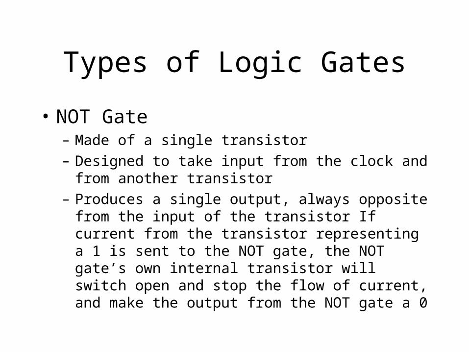
• NOT Gate– Made of a single transistor
– Designed to take input from the clock and from another transistor
– Produces a single output, always opposite from the input of the transistor If current from the transistor representing a 1 is sent to the NOT gate, the NOT gate’s own internal transistor will switch open and stop the flow of current, and make the output from the NOT gate a 0
NOT Gate
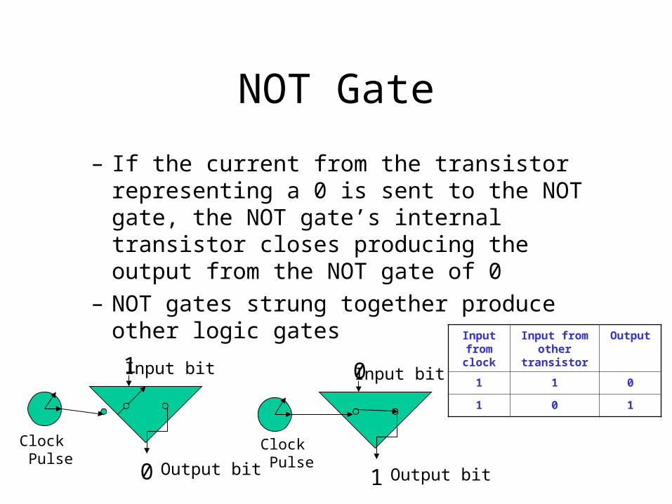
– If the current from the transistor representing a 0 is sent to the NOT gate, the NOT gate’s internal transistor closes producing the output from the NOT gate of 0
– NOT gates strung together produce other logic gates
Input from clock
Input from other transistor
Output
1 1 0
1 0 1
0 Input bit
1 Output bit
Clock Pulse
Clock Pulse
1 Input bit
0 Output bit
OR Gate
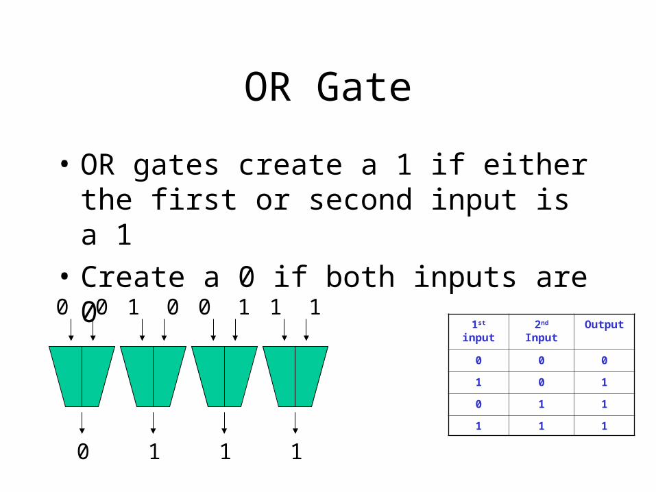
• OR gates create a 1 if either the first or second input is a 1
• Create a 0 if both inputs are 0
1st input 2nd Input Output
0 0 0
1 0 1
0 1 1
1 1 1
0 0
0
1 0
1
0 1
1
1 1
1
AND Gate
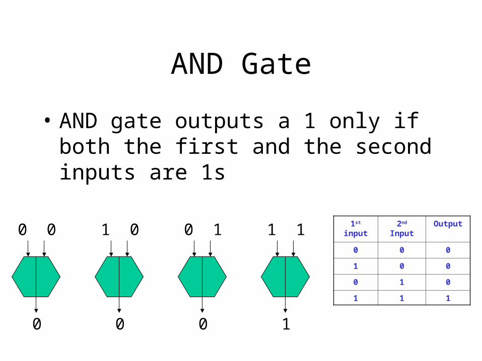
• AND gate outputs a 1 only if both the first and the second inputs are 1s
0 0
0
1 0
0
0 1
0
1 1
1
1st input 2nd Input Output
0 0 0
1 0 0
0 1 0
1 1 1

XOR Gate
• XOR gate puts out a 0 if both inputs are 0 or if both are 1– Generates a 1 only if one of the inputs is 1 and
the other is 0
0
0 0
1
1 0
1
0 1
0
1 1 1st input 2nd Input Output
0 0 0
1 0 1
0 1 1
1 1 0
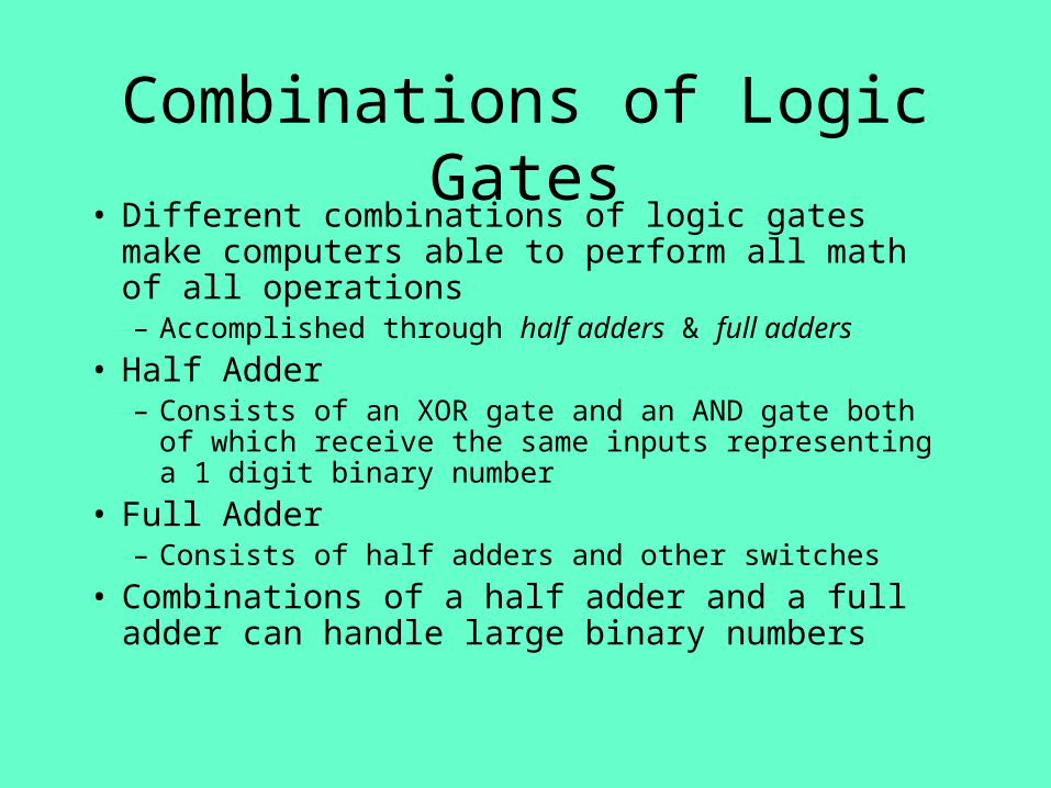
Combinations of Logic Gates• Different combinations of logic gates make computers
able to perform all math of all operations– Accomplished through half adders & full adders
• Half Adder– Consists of an XOR gate and an AND gate both of which
receive the same inputs representing a 1 digit binary number
• Full Adder– Consists of half adders and other switches
• Combinations of a half adder and a full adder can handle large binary numbers
Part 4Major Concepts
• Chapters 10-12– Electromagnetism– Reading/writing files– Disc formatting– Disc compression, file compression– Disc defragging
Electromagnetism
• Conductivity– The ability of a material to conduct electrical current
– Some materials are more conductive than others and lose electrons in the outer most layer of the atom more freely compared to others
• Non-conductive– Do not conduct electrical current, do not lose electrons
– Also known as insulators
Electromagnetism• Each electrical device creates “stray” – unwanted
electromagnetic fields called noise• Computers are designed to eliminate or reduce noise
because of its negative impact on PC operation– Nonconductive wires added to cables– Insulators around items that create large amounts of noise
• More noise makes it necessary to increase the electrical power to get signals pushed through devises
• Stronger signals create more noise
Electromagnetism
• When a wire moves through a magnetic field, the interaction creates an electrical current inside the wire
• We will see that this is the basis of how read/write heads inside floppy drives and hard drives operate
Electromagnetism• Electromagnetic (EM) Radiation Spectrum
– Includes the complete range of energy beginning with the longest radio waves through visible light and including rays produced by radioactive atoms
• All energy in the EM spectrum expands in waves at the speed of light– Electromagnetic fields are measured in terms of their
frequency – the number of times a wave is produced in a period of time, usually 1 second
– Measured in hertz
Electromagnetism
• Frequency in an EM field is inversely related to its wavelength– Wavelength – the distance between two
identical points in adjacent waves– The higher the frequency of the signal, the
shorter the wavelength– The lower the frequency of the signal, the
longer the wavelength
Electromagnetism
• Electromagnetic fields are used as signals to carry data by varying the waveform– Frequency Modulation
• Carries data by varying the frequency of a waveform – the number of times a waveform repeats itself in a measure of time
– Amplitude Modulation• Carries data by varying the amplitude or height of a
waveform
Writing and Reading Bits to a Disk
• Before data is stored on disks, microscopic iron particles are scattered in random order throughout the disk surface
• To organize the particles, electricity pulses through a coil in the read/write head creating a magnetic field that magnetizes the particles on the disk
• This arranges the particles with their positive poles pointing toward the negative end of the read/write head and the negative poles pointing toward the positive end of the head
Writing and Reading Bits to a Disk
• Bands of aligned magnetized particles are created in succession as the disk spins
• Two bands are created to represent the smallest discrete unit of data, a single bit
• A binary 1 is created by swapping the orientation in two bands of particles– This aligns like ends next to each other in two bands
• A binary 0 is created by orienting two bands of particles identically in the same direction
Writing and Reading Bits to a Disk
• To store a second bit, the polarity of the first band is always opposite of the band preceding it to indicate that it’s beginning a new bit
• To read data, no current is sent to the read/write head– As the disk platter spins, the particles themselves create
a magnetic field that generates current that travels in one direction or the other through wires leading from the head
Writing and Reading Bits to a Disk
• The direction of the current traveling through the head depends on the polarities of the bands
• By sensing changes in the direction of the current coming from the disk, the CPU can tell if the data is a 1 or a 0
Formatting a Disk
• Before any disk can have material stored on it, it must be Formatted– Formatting organizes the disk so the the same way
every time so any PC can store and retrieve data from any formatted disk
• Each disk is divided radially in sectors which are similar to a slice of pie
• Each disk also contains concentric circles called tracks
Formatting a Disk
• Cluster– Two or more sectors on a single track– Cluster is the minimum unit the operating
system uses to store information
• The number of sectors, tracks, and clusters that a drive can create on a disk’s surface determine the capacity of the disk
Formatting a Disk
• File Allocation Table [FAT] or VFAT in Windows– A special file located in sector 0 of the disk– VFAT made large file names possible due to its ability to
store 255 characters– Also where the operating system stores information
about a disk’s directory or folder structure, and what clusters are used to store which files
• Windows 98 introduced FAT32 allowing hard drives larger than 2 GB to be formatted as a single disk
Disk Compression• Prior to disk compression files were saved to
clusters but did not store data in the cluster in the most efficient manner– Given a cluster size of 8KB a file 18KB in size would
take 3 full clusters to store– Clusters were used as all or nothing storage spaces– In the example above the first 16KB of the file are
stored neatly into 2 clusters, and the remaining 2KB are stored in a single 8KB cluster but leave 6KB free and unusable by other files
Disk Compression
• Compressed Disks get more effective use of storage by creating a single file on the drive known as a compressed volume file or CVF
• A CVF is treated by the OS as if it were a drive itself
• When the OS writes a file to the CVF, it uses only as much of a cluster as it needs
• Each file is separated by a very small space of blank disk space
File Compression
• File Compression, also know as zipping a file reduces the size by eliminating redundancies in the file– Known as lossless compression – because
every bit in the file can be restored exactly as it was originally written
• The compression uses a algorithm called an adaptive dictionary-based algorithm
File Compression
• The compression program reads the file and looks for recurring patterns of data
• When a pattern is identified, it writes the pattern to a dictionary instead of writing the pattern in the line where it exists
• The dictionary is then stored as part of the compressed file
File Compression
• Where the pattern would have been written the program places a pointer that tells where the omitted pattern is located in the dictionary
• When a compressed file is read, pointers are encountered and compressed files are read on the fly by retrieving the file and writing it to RAM
• File types are directly related to how much it will shrink during compression
Disk Defragging
• When the first file is saved to a disk, it is saved on a track in clusters that are contiguous– This means that the file is stored in one
continuous stream of clusters
• Over time, as files are erased, empty clusters are left behind– These clusters are seldom contiguous
Disk Defragging
• Since a file may not fit neatly into one or more clusters, they are stored in many clusters that are not contiguous– Files are written to many clusters in many
locations – in other words, files are fragmented into many clusters throughout the disk
Disk Defragging
• Fragmentation slows down the drive due to the constant seeking the read/write heads must do to track down all parts of a file
• Defragmentation is a software controlled operation that moves scattered parts of files into contiguous clusters
Disk Defragging• Defragging begins by moving contiguous clusters
of data to other unused parts of the drive– This opens large areas of contiguous space
• The drive then moves fragmented parts of a file into the newly opened space and stores them in a contiguous manner
• The process continues until all files possible are stored in a contiguous manner
Part 4Major Concepts
• Chapters 13-14– CD-ROM technology– CD-R discs– DVDs– CD-RW and DVD RAM
Optical Storage
• Optical Storage Media– CDROM– CDR– CDRW– DVD– DVD-RAM
• All use a similar technology, just slightly different variations
CD-ROM Drive
• The beam penetrates the protective layer of plastic and strikes a reflective payer that looks like aluminum
• The surface of the disc is made up of high and low spots called ‘lands’ and ‘pits’– Lands are flat areas– Pits are tiny depressions
• These two surfaces are a record of the 1s and 0s used to represent data to the PC

CD-ROM Drive
• Light that strikes a pit is scattered and not sent back to the detector
• Light that strikes a land is reflected directly back to the detector and passes through a prism and to a light-sensing diode
• Each pulse of light generates a small electrical voltage
• Each voltage is matched against a timing circuit to generate a stream of 1s and 0s
CD-ROM Drive
• On a CD-ROM disc, data is contained in a single track that spirals in a track from the center to its circumference
• Each track is divided into sectors, but each sector is the same size opposed to a metal disc where the size of the sector varies with distance from the center of the disc
• Using Constant Linear Velocity the disc drive constantly varies the rate that the disc spins at
CD-ROM Drive
• Therefore, as the detector moves toward the center of the disc, the disc must speed up
• This roughly equates to more sectors, more data
CD-R Discs
• Dye layer is designed to absorb light at specific frequency, the frequency of the laser beam– As it absorbs light, it creates a mark on the disk in one
of three ways• By bleaching the dye
• By distorting the dye
• By making the dye bubble
– Regardless of how the mark is created, the result is a distortion called a stripe along the spiral track of the disk
How a DVD Works
• One or two sides?
• Layers of a DVD– Polycarbonate plastic– Opaque reflective material– Transparent film– Protective plastic
How a DVD Works
• Data is represented by a series of lands and pits, similar to a CD-ROM but much smaller– Lands and pits are formed on two layers of the
DVD opposed to one on the CD-ROM– DVDs use lasers to read data
• Shorter wavelength – makes the beam able to read smaller lands & pits on the DVD
How a DVD Works
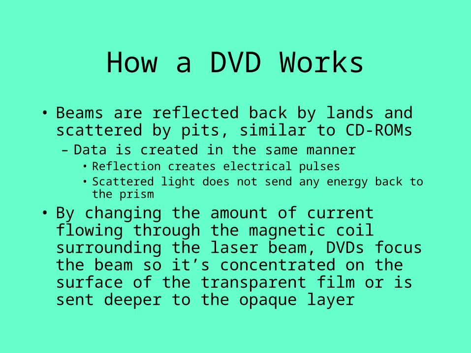
• Beams are reflected back by lands and scattered by pits, similar to CD-ROMs– Data is created in the same manner
• Reflection creates electrical pulses• Scattered light does not send any energy back to the prism
• By changing the amount of current flowing through the magnetic coil surrounding the laser beam, DVDs focus the beam so it’s concentrated on the surface of the transparent film or is sent deeper to the opaque layer
How a DVD Works
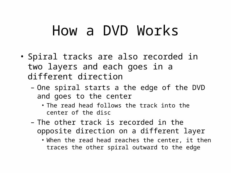
• Spiral tracks are also recorded in two layers and each goes in a different direction– One spiral starts a the edge of the DVD and goes to the
center• The read head follows the track into the center of the disc
– The other track is recorded in the opposite direction on a different layer
• When the read head reaches the center, it then traces the other spiral outward to the edge
CD-RW and DVD-RAM
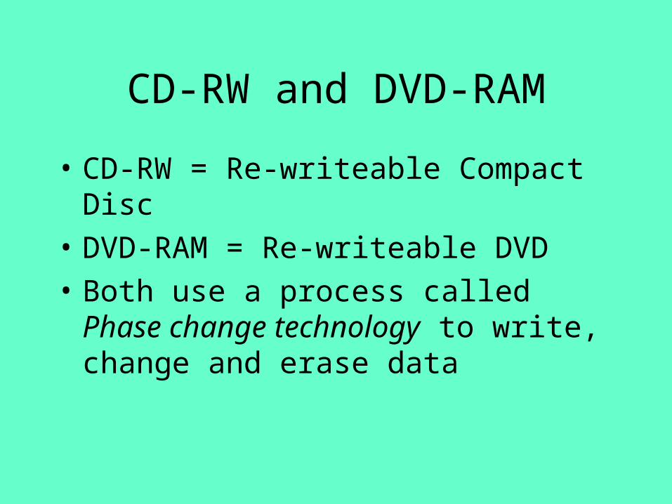
• CD-RW = Re-writeable Compact Disc
• DVD-RAM = Re-writeable DVD
• Both use a process called Phase change technology to write, change and erase data
CD-RW and DVD-RAM
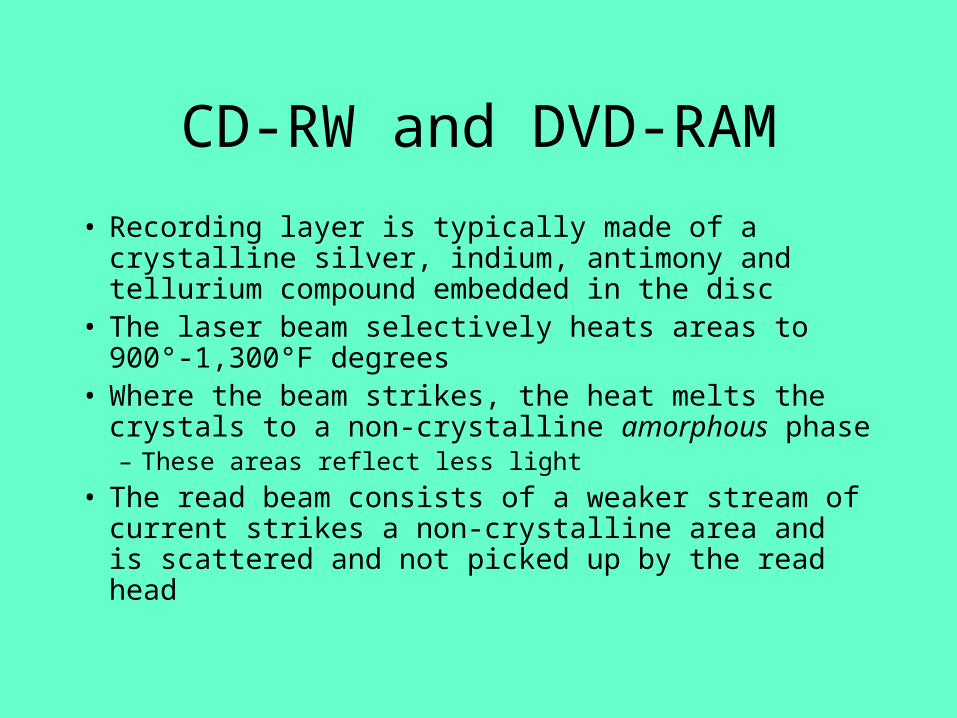
• Recording layer is typically made of a crystalline silver, indium, antimony and tellurium compound embedded in the disc
• The laser beam selectively heats areas to 900°-1,300°F degrees
• Where the beam strikes, the heat melts the crystals to a non-crystalline amorphous phase – These areas reflect less light
• The read beam consists of a weaker stream of current strikes a non-crystalline area and is scattered and not picked up by the read head
CD-RW and DVD-RAM
• A process called the annealing phase erases the data on the disc
• Uses a beam of 400°F to melt the that the compound returns to its crystalline state
• The beams that are used by each type differ in wavelength– DVD-RAMs are are able to read and write data in a
more compact manner, which makes them able to store more data in the same size area as a CD-RW
Part 5Major Concepts
• Chapters 15-16– Energy to data– Analog and digital conversion– Scanners, digital cameras– Power supply's– How AGP works
How Energy Turns Into Data
• Perceptions are analog – one continuous wavy line of events moving at predictable rates
• But really – things are more digital – discrete separate events with different numerical values
• Digital to Analog Converters [DACs] and Analog to Digital Converters [ADCs] handle all conversions to and from each form of data
• Charged-Coupled Devices turn light into electrical energy
• Light is turned into electrical energy
Analog and Digital Converters
• Visible light and audible sound both travel in waves – The brighter the light, the more electrical current it can
be converted into– The louder the sound, the more electrical current it can
be converted into
• Computers convert all analog input into digital values it can use
• The opposite conversion must also take place upon sending digital data to output devices
Analog Converters
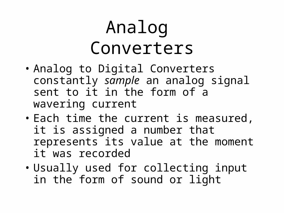
• Analog to Digital Converters constantly sample an analog signal sent to it in the form of a wavering current
• Each time the current is measured, it is assigned a number that represents its value at the moment it was recorded
• Usually used for collecting input in the form of sound or light
Digital Converters
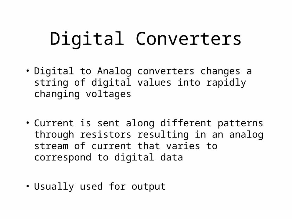
• Digital to Analog converters changes a string of digital values into rapidly changing voltages
• Current is sent along different patterns through resistors resulting in an analog stream of current that varies to correspond to digital data
• Usually used for output
Digital and Analog Conversion
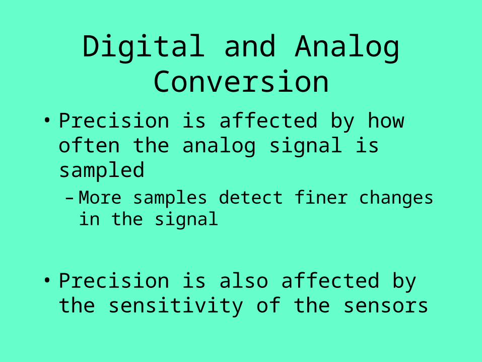
• Precision is affected by how often the analog signal is sampled– More samples detect finer changes in the signal
• Precision is also affected by the sensitivity of the sensors
Digital and Analog Conversion
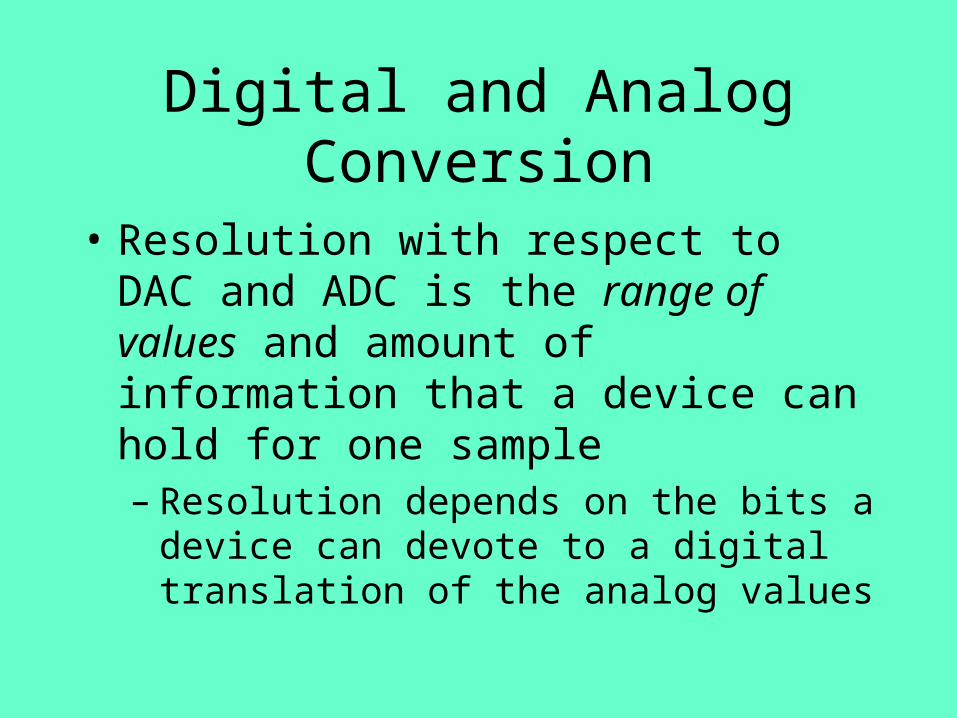
• Resolution with respect to DAC and ADC is the range of values and amount of information that a device can hold for one sample– Resolution depends on the bits a device can
devote to a digital translation of the analog values
Digital and Analog Conversion
• If a DAC has only one bit to represent a sample of an analog signal it can only show whether the analog signal is on or off, black or white
• If a DAC has 16 bits to express each digital sample it can represent 256 shades of red– Higher the resolution number, the higher the definition
in either sound or color
How Scanners and Digital Cameras See
• Scanners and digital cameras have to convert different amounts of light into corresponding energy levels, and eventually 1s & 0s
• Both use a charge-coupled device [CCDs] to solve the problem– A camera must divide light passing through the lens
into green, red, and blue elements– It must also register the light that falls at the same
moment on a very small area – the size of 2 postage stamps

How an Uninterruptible Power Supply Works
• Two types– Offline– Online
How an Offline Uninterruptible Power Supply Works
• Offline or passive UPSs split incoming current into two branches– One feeds the normal power of the PC– The other passes through a battery charger which changes
the current from AC to DC to keep the battery charged
• If power fails, within 4-20 milliseconds the microprocessor inside the the UPS closes a switch that sends DC through an inverter and turns the battery’s DC current into AC needed by the PC
How an Online Uninterruptible Power Supply Works
• Online or serial UPSs feed all current through an AC-DC converter, from there to a battery, then to an inverter and then to the PC– This way, the UPSs battery is always charged
and supplying current to the PC
• If power fails, a microswitch breaks the connection between the wall and the UPS and current flows from the battery
How AGP Works
• AGP chipset replaces the PCI bus’ input/output controller
• Coupled with a Pentium 4 chip and RDRAM memory capable of 3.2GB/sec data transfer
• Handles transfers of data among memory, CPU and the ISA controller – all simultaneously
• Also handles transfers to the PCI local bus at 132MB/sec
How AGP Works
• The AGP chipset puts the AGP port on the same part of the bus as memory, with data transfers of up to 1056MB/sec between those items
• The arrangement allows AGP accelerated graphics adapter to replace the adapter on the PCI bus– Eliminates the need for video RAM
• Provides faster Direct Memory Access enabling some to read/write to memory without the help of the CPU
• Sends four bursts of 32 bits of data with every clock tick equaling 1056MB/sec data transfer to and from RAM
Part 5Major Concepts
• Chapters 17-19– Port Types– Peripherals
• Keyboards
• Displays– VGA
– LCD
– DLP
Types of Common Ports
• Parallel
• Serial
• IDE
• USB
• SCSI
How a Parallel Port Works
• 25-36 pin connection– PC side has 25, printer side has 36 – with a different
connector on each end
• Parallel ports can send several bits of data across eight parallel wires simultaneously
• Similar to a formation of soldiers– Think of a platoon of soldiers marching 8 abreast– When the platoon reaches a line on the ground, 8 soldiers
cross the line at one time, followed by the next 8 and so on
• Faster than serial ports
How a Serial Port Works
• Think of soldiers in a single file line, one behind another– When the soldier reaches a line on the ground,
he and only he can cross at one time, then the next, the next and so on
– Different than the 8 simultaneously crossing on the parallel port
• Slower than parallel port
Universal Serial Bus‘USB’
• USB cable contains 4 wires– 2 for electrical power– 2 for sending data and commands
• Two speeds of data transfer via USB cable– High speed = 12Mbs [megabits] a second
• Used for monitors, scanners, printers
– Low speed = 1.5Mbs• Used for keyboard or mice
• Serial ports send ~ 100kbs• Parallel ports send ~ 2.5Mbs
Universal Serial Bus‘USB’
• Cables can connect to a USB hub – capable of connecting to many other USB devices – Expands the 2 ports on the PC to many more
• Each USB device can act as an extension to another USB device e.g. from a hub to a monitor, to speakers, to a keyboard and so on, up to 127 devices

IDE Connections
• Each of the connections can connect to a hard drive
• E-IDE can control floppy drives, CDROMs, and tape drives– Devices must be E-IDE compatible and mounted inside
the PC
• For each pair on a single cable, one device is master and the other is slave– This serves as a traffic light for signals destined for one
or the other
Small Systems Computer Interface‘SCSI’
• Last device in the daisy chain must have a terminator to provide a ground for the port not used in the last device
• Cable is a flat ‘ribbon’ cable with 50 lines inside
• Two speeds of data transfer– Most common, 8 lines used to send data
• Capable of 10-20MB second
Small Systems Computer Interface‘SCSI’
• Wide SCSI uses a 16 bit path, capable of 40MB second
• All data transfer managed by the SCSI controller card inside the PC
• Each wire of the ribbon cable has a specific purpose– Some are for specific bits in a byte – 0 bit – parity bit
– Some are command lines that send specific commands like BSY, ANT, ACK
How a Keyboard Works
• When you press a key, you create a change in the current flowing through a circuit associated specifically with that key
• A microprocessor in the keyboard detects the increase and decrease in current from the key that was pressed
• Detecting both an increase and decrease, the processor can tell when the key was pressed and released
How a Keyboard Works
• Each key has a unique set of codes– Processor can distinguish between the left and
right shift keys
• To distinguish real signals from an aberrant current fluctuation, the keyboard is scanned hundreds of times per second
• Depending on which key is pressed, the processor will generate a scan code
Super VGA Display• Adapter sends signals to three electron guns located in
the back of the monitor’s cathode ray tube [CRT]• Gun shoots 3 streams of electrons
– One for each of the 3 primary colors• Intensity controlled by the signals from the adapter
• Adapter also sends signals to the magnetic deflection yoke– This focuses and aims the electron beams– Signals also help determine the resolution of the monitor –
number of pixels horizontally and vertically and the refresh rate – how frequently the screen is redrawn
Super VGA Display
• The electrons from the gun strike phosphors on the inside of the screen– Phosphors glow when struck by electrons
• One each for red, green and blue
– Stronger electron beam = brighter color• If each red, green, and blue phosphor is struck equally, the
result is a white dot
– After the beam leaves a phosphor, it glows for a short time – called persistence
– For an image to remain stable, phosphors must be must be reactivated repeatedly by the electron stream
LCD Screens
• Liquid Crystal Display• Named for the fact that there is a layer of
liquid crystal material sandwiched in between the front and back panels that make up the LCD panel
• Light emanating from a panel at the back of the screen spreads out in waves that vibrate in all directions
LCD Screens
• The light emerging from each liquid crystal cell passes through one of three color filters – red, blue, or green [arranged very close to each other]
• The colored beams of light pass through a second polarizing filter that only passes waves that are vibrating more or less vertically
• Light that passed through a liquid crystal with a full charge is now oriented perfectly to pass through the second filter
LCD Screens
• Since the filter is not precise, some of the light waves pass through that were only partially charged
• Those without a charge are blocked completely• Since there are millions of combinations of
charged cells producing millions of combinations of twisted molecules, the color on the screen is able to represent millions of colors to our eyes
Digital Light ProcessingDLP
• DLP produces brighter, sharper images over a conventional projection system
• By shinning a light through a spinning wheel divided into red, blue and green sections, each color is produced 60 times a second
• After passing through the spinning disc, the light strikes a panel of 508,800 microscopic mirrors on the surface of a DLP chip
• The mirrors reflect the light through a lens and onto a screen

Part 5Major Concepts
• Chapters 20-21– Mice
• Mechanical
• Optical
– Touchpads and pointing devices
The Mechanical Mouse
• Each roller is attached to an ‘electronic’ wheel– A plastic wheel with tiny metal contact points that
conduct electricity on it– Known as an Encoder– As the rollers turn, they rotate the encoders
• Each encoder makes contact with a pair of electrical bars that pick up the signals made by the contacts as they spin past the bars
• Each contact results in the generation of an electrical signal
The Mechanical Mouse
• The number of signals indicates how many points the contact bars have touched– The greater the number of signals, the farther the
mouse is moved– The more frequent the number of signals, the faster you
are moving the mouse
• Mouse direction:– the ratio between the number of vertical signals to
horizontal signals indicates the direction of the cursor travel on the screen
The Mechanical Mouse
• Tapping either of the buttons on the mouse sends a signal to the PC which– results in an interrupt and tells the CPU to
divert it’s attention to the command represented by the mouse click
• Based on the location of the cursor when you click it
• Based on the number of clicks you send via the buttons
The Optical Mouse
• Uses a small light projected onto the surface that the mouse travels over
• A digital camera takes extreme close up pictures of– Different shapes, ripples, pits, bumps and brightness
differences in the surface the mouse travels over
– Takes 1500 pictures a second
– Digital signal processor analyzes each picture to calculate the speed and direction of the mouse
Touchpads
• A layered pad consisting of a sandwich of:– Rubber– Electrodes aligned vertically– Electrodes aligned horizontally
• Positive and negative charges build up on each layer independently– Creates an electrical field between the layers
• Integrated circuits for each layer [vertical and horizontal] sample the strength of each field’s electrical potential – or – mutual capacitance
Touchpads
• Capacitances are most affected by the center of the finger
• By reading the capacitances of adjoining intersections, the touchpad can identify the finger’s center
• Location is fed to Windows to position the cursor or arrow
• Capacitances measured about 100 times per second
Pointing Sticks
• Resistors made of two electrical contacts separated by a film that resists the flow of electricity
• When pressure is exerted in a certain direction the contacts are pushed closer together– Creates a better connection between the 2 contacts– The closer the contacts become, the better the connection between
the plates, the more electricity flows between the contacts
• A circuit monitors the amounts of electricity flowing between the plates and translates this information into cursor speed and direction
Part 5Major Concepts
• Chapters 22-25– Modems and communications– Biometrics in computers
• Fingerprints
• Speech and voice recognition
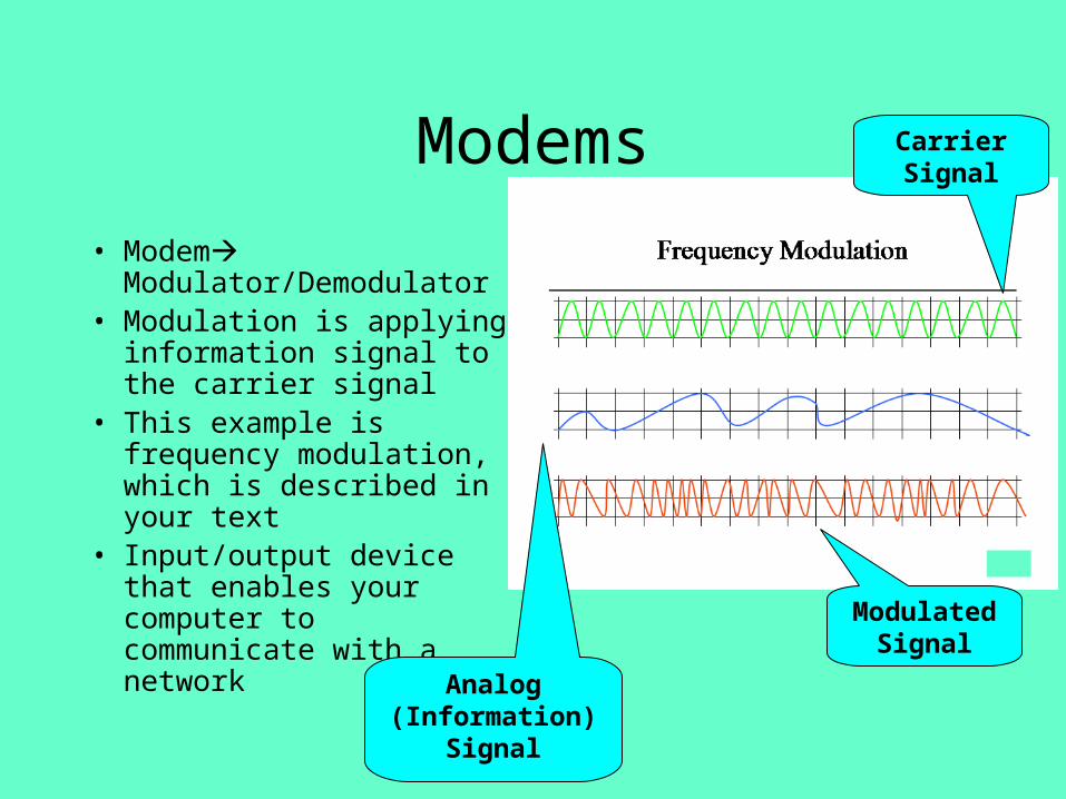
Modems
• Modem Modulator/Demodulator
• Modulation is applying information signal to the carrier signal
• This example is frequency modulation, which is described in your text
• Input/output device that enables your computer to communicate with a network
Carrier Signal
Modulated Signal
Analog (Information)
Signal
Modem Info
• Modems are used to convert digital computer information into a form the analog network can understand
• Phone networks were built to support the human voice—analog
• Modems have several variations—some proprietary, some not really even modems– DSL/Cable are “Terminal Adapters” which “speak”
only digital, but still provide the interface between the computer and the network
Modem Data Structure
• Can use many different schemes to ensure the message gets through– Start/Stop bits—used to define the beginning and end of
useful information• But—you need to know the rules when you set up the
connection
– Parity bits—used to detect (not correct) errors• Odd—add up the 1’s in a data grouping, add a 1 if even, a 0 of
odd• Even—add up the 1’s in a data grouping, add a 1 if odd, a 0 if
even
• Full Duplex or Half duplex transmission
Fingerprint Recognition
• Fingerprints recognition in text is described for two cases– Identity verification
• Used for a one-to-one verification of a person’s identity• System or facility access• Part of the biometrics field, related to information security
– Identity determination• Used for a one-to-many comparison of an unknown identity,
checked against many samples in a database• Used for criminal investigation, missing or unknown persons
cases, etc

Speech Recognition
• Like with the Palm PC, a large degree of reliance is placed on a “best-guess” solution
• Voice is inputted– Quality is dependent on the microphone and system
sophistication
– Converted to digital
• Speech is matched against known model– Obtained from English (or other language structure)
– User “enrollment” to the software
Voice Recognition
• Software has an acoustic recognizer that compares the user corrected digital stream to a rule-based database to that assigns a value of the voice input
• If a close match is obtained, great• If not, context may be used to determine if their,
there or they’re was meant• If context doesn’t work, then manual intervention
is needed
Part 6Major Concepts
• Chapters 26-28– Multimedia
• Sound
• Video
– Virtual Reality– 3D Graphics
Components of the Sound Card (Computer)
• Input and output jacks – Input from microphones– Output leading to cool things like subwoofers and
surround sound
• Analog to Digital Converter (ADC)– Takes input from the input jacks and translates analog
into binary
• Digital to Analog Converter (DAC)– Takes binary information from the computer and
translates into an analog signal for your speakers

Components of the Sound Card (Computer)
• Digital Signal Processor (DSP)– This is the CPU for the Sound Card– Relieves the Main CPU from being burdened with
sound processing responsibilities– Main CPU feeds to or receives information from the
DSP
• Memory– Provides the instructions needed for the DSP to operate– New systems are “software” upgradeable, or more
accurately, “firmware” upgradeable
VR Input/Output Devices
• Helmet– Provides video output in a clever way so that
you feel you are in the VR world—stereoscopic views (anyone have the stereo viewers when growing up?)
– Also can incorporate sensors so that the helmet is also an input device (where are you looking—gamers user a mouse or joystick to do this)
VR Input/Output Devices
• Glove– Input device incorporating a fiber optic network
on the fingers to detect what they are doing– Can incorporate a 6 degrees of freedom (6DOF)
sensor as well to detect where the hand is
• Accelerometer– Used to detect where a joystick or other device
is directing the action to go
3D Graphics
• Divide the world into vertical, horizontal and depth—defines the position of a single point
• Three points are minimum necessary to define a plane in 3D space—what shape is defined by three points?– Triangles are easier to compute than other shapes, so are often used– More complex shapes can be defined by a series of triangles
• This is a load on the processor to figure out—that’s why graphics cards are so popular…they have specialized processors that relieve the main processor of some of the load
• Main processors also have specialized instruction sets to deal with graphics– MMX is fairly recent technology, but was one of the first efforts to do this
Part 7Major Concepts
• Chapters 29-31– Types of networks– Network Transmission media
• Cabling
• Protocols
• Control devices
– 7 Layer OSI model
Client/Server Networks• Local Area Network (LAN)
– Made up of servers and clients• Servers or ‘hosts’ are computers that perform specific functions
– File servers– Electronic mail servers– Web servers
• Network Operating System– Manages the movement of files and data on a network by
maintaining the rules that govern file transfer, communications, and system operation
• Microsoft NT, 2000• Novell• Unix
Types of Clients• Clients
– Personal computers attached to a server via a LAN
• Fat Client– Computers that run most of the their programs from their own hard
drive and use a minimum of network services
• Thin Client– Computers that run all of their programs and services from a server
• Use their own microprocessor• May have no hard drive at all
• Dumb Terminal– No local computer, no CPU– A monitor and a keyboard used as an interface to a mainframe
computer
Wide Area Network(WAN)
• WANs are groups of smaller LANs• Cover a wider geographical area than LANs• Connected via communication links capable of
fast data transfer– Telephone lines– Satellites– Wireless connections
• Also connected via the internet through virtual private networks (VPNs) that encrypt information to keep others from seeing it
How Networks Connect
• Network Interface Card (NIC)– Usually a PCI card that connects the PC to the network
backbone
• Ethernet– The most common protocol or communication rules used in
LANs• Not a single product
• Transmission Speeds– 10BASE-T, speeds up to 10Mbps– 100BASE-T, speeds up to 100Mbps – also called Fast
Ethernet– Gigabit Ethernet, speeds up to 1,000Mbps
Network Connections and Cabling
• NIC Connections– RJ-45
• Most common• Looks like an oversized telephone connection• Uses twisted copper wire as medium, similar to
phone lines
– Coaxial or BNC• Not as common• Looks like cable TV, same cable and connectors
Network Connections and Cabling
• Twisted Pair Cable– Also called CAT 5
• Name short for ‘Category 5’ wiring schema
• Name describes cables, connections, and connectors
– Capable of 10BASE-T, 100BASE-T and 1000Mbps speeds
– Can sustain a break in the cable without disrupting the entire network
The 7 Layer OSI Model
• Application Layer (7)– The only part the user sees– Converts a message’s data into bits and attaches a
hearder identifying the sending and receiving computers
• Presentation Layer (6)– Translates message into a form the receiving computer
can understand– Can compress and encrypt data– Adds a header specifying the language, compression and
encryption methods used
The 7 Layer OSI Model
• Session Layer (5)– Manages the setting up and taking down of the
association between two communicating end points that is called a connection
• Transport Layer (4)– Ensures the reliable arrival of messages and
provides error checking mechanisms and data flow controls
The 7 Layer OSI Model
• Network Layer (3)– Network layer knows the address of the neighboring
nodes in the network, packages output with the correct network address information, selects routes
• Data Link Layer (2)– Supervises the transmission, checks the checksum,
addresses and duplicates the packets, keeps a copy until all packets have been received by the next point in the path
The 7 Layer OSI Model
• Physical Layer (1)– Supports the electrical or mechanical interface
to the physical medium. For example, this layer determines how to put a stream of bits from data link layer on to the pins for a parallel printer interface, an optical fiber
The 7 Layer OSI Model• At the receiving node, the layered process is reversed
– Physical layer receives and converts message into bits– Data link layer recalculates the checksum, confirms arrival,
logs packets – Network layer recounts packets for security– Transport layer reassembles packets – Session Layer holds message until it is complete– Presentation layer decrypts, expands and translates message– Application layer identifies recipient, directs data to the
correct application