Embed Size (px)
Citation preview
Title: YALE OFFICE OF FACILITIES PROCEDURE MANUAL
Chapter: 01 - Yale Design Standard
Division: HVAC Standards
Section: 23 07 00 HVAC
Insulation
Date: 06/15/16
Author: Office of Facilities
CC: Project Folder
Page 1 of 29
Date Description of Change Pages / Sections Modified ID
6/15/16 Entire document - mgl44
PART 1 - INTRODUCTION
A. This section pertains to insulation requirements for duct, pipe, and equipment for both
building and utility systems. Building insulation standards are followed by utility
insulation standards.
PART 2 - DUCT INSULATION FOR BUILDING SYSTEMS
2.1 General Duct Insulation Requirements
A. Purpose
1. Provide insulation for energy conservation, personnel protection, condensation
control, freeze protection, noise control, and fire protection.
B. This Section specifies the requirements for materials and application of insulation to
ducting, and equipment which is not pre-insulated as part of a packaged system.
C. Flame/Smoke Spread Ratings: composite ratings of 25/50 per ASTM E84, UL 723, and
NFPA 255.
D. OSHA: Comply with OSHA requirements for materials, accessories, and personnel
protection.
E. Design insulation systems based on the minimum following guidelines
1. Governing Code requirements
2. SMACNA Guidelines
3. ASHRAE Fundamentals Handbook – Insulation for Mechanical Systems
4. ASHRAE Energy Standards 90.1 and 189.1: Comply with ASHRAE where
insulation requirements are more restrictive than indicated in this Specification.
5. LEED Requirements
6. Mechanical Insulation Design Guide by the National Mechanical Insulation
Committee.
7. Thermal values to prevent condensation.
8. NFPA requirements
9. Appropriate vapor and water barriers.
F. Systems requiring insulation, but not limited to are:
1. Supply duct, heating and cooling
2. Return duct, heating and cooling
Title: YALE OFFICE OF FACILITIES PROCEDURE MANUAL
Chapter: 01 - Yale Design Standard
Division: HVAC Standards
Section: 23 07 00 HVAC
Insulation
Date: 06/15/16
Author: Office of Facilities
CC: Project Folder
Page 2 of 29
3. Outdoor air duct and plenums
4. Louver blank-off section at outdoor intakes
5. Kitchen exhaust duct
6. Equipment part of water and air distribution systems.
G. Installation Requirements
1. Labeling and flow arrows complying with Mechanical Identification requirements
shall be applied to the exterior surface of insulation systems.
2. Insulation shall be continuous through wall and ceiling openings.
3. For outdoor applications duct shall slope away from equipment which it connects to,
and at locations where it enters or exits a structure.
4. Provide insulation stand-offs, for volume damper handles and similar devices.
5. At location of duct supports and hangers, there shall be a rigid thermal break to
prevent the compression of insulation. Rigid thermal break shall be of sufficient
thermal resistance to prevent internal and external condensation.
6. At locations such as access doors, and where equipment must be accessed,
insulation shall be removable and be replaceable without compromising the integrity
of the insulation and vapor barrier system.
7. Insulation shall not be installed prior to duct leakage and associated equipment
testing.
H. Insulation Securement Requirements.
1. Duct insulation shall be secured with the use of PBH Dynastick Mechanical Type
Fastener insulation hanger and adhesive, regardless of surface orientation, and area.
2. For kitchen exhaust systems, manufacturer instructions shall govern external
insulation fastening requirements.
I. Internal lining of duct.
1. Exposed internal lining of duct is prohibited for the purpose of insulation.
For the purpose of sound attenuation, internal lining of duct shall be allowed
pending approval by Yale. Where duct is internally lined for attenuation purposes,
this shall not omit the requirement of external insulation.
J. Outdoor Insulation Requirements
1. Outdoor duct shall be round double-wall, gasketed, and insulated between inner and
outer layer of ducts.
2. Where round double-wall insulated duct is not feasible for outdoor applications,
insulate rectangular duct as outlined within the corresponding section of this
standard.
2.2 Duct Insulation Minimum Requirements Building Systems
Title: YALE OFFICE OF FACILITIES PROCEDURE MANUAL
Chapter: 01 - Yale Design Standard
Division: HVAC Standards
Section: 23 07 00 HVAC
Insulation
Date: 06/15/16
Author: Office of Facilities
CC: Project Folder
Page 3 of 29
A. External Duct Insulation
1. Materials:
a. Type A: flexible glass fiber insulation, thickness as scheduled, 3/4-pcf density,
with UL-labeled foil vapor barrier. Thermal conductivity shall be no greater
than 0.31 Btu-inch per hour-ft2 degrees F at 75 degrees F.
b. Type B: rigid glass fiber insulation per ASTM C612, thickness as scheduled,
3-pcf density, with UL-labeled, foil-reinforced, kraft-faced vapor barrier.
Thermal conductivity shall be no greater than 0.23 Btu-inch per hour-ft2
degrees F at 100 degrees F.
c. Type C: rigid glass fiber insulation per ASTM C612, thickness as scheduled,
6-pound density with UL-labeled, foil-reinforced, kraft-faced vapor barrier.
d. Type D: foamed plastic of closed cell structure, thickness as scheduled.
Thermal conductivity no greater than 0.28 Btu-inch per hour-ft2 degrees F at
75 degrees F and maximum water vapor transmission rating of 0.1 perms.
2. General:
a. Install materials in accordance with the manufacturer's instructions.
3. External Duct Insulation Minimum Installation Requirements (Types A, B, C and
D):
a. Application:
1) Secure insulation to ductwork using a combination of adhesive and
mechanical fasteners, such as impale anchors.
2) Install without sag on the underside of ductwork using a combination
adhesive and mechanical fasteners. Bend over nail tips after installation
of washers to facilitate sealing of vapor barrier and to preclude injury.
Stop and point insulation around access doors and damper operators to
allow operation without disturbing wrapping.
3) Lap joints and seams of external of batt type insulation a minimum of 3
inches overlap 3 inches on center. Secure as required.
4) Seal insulation with vapor barrier adhesive or tape matching jacket type
to maintain the vapor barrier. Pay particular attention to penetrations by
mechanical fasteners, joints, seams and to ends and edges.
b. Rigid Insulation: Band insulation 12 inches on centers.
c. Outdoor ducts: Cover insulation with Polygaurd, or equal product.
d. The top surface of all exterior exposed ductwork shall be sloped and capped
with galvanized sheet metal constructed with waterproof seams and joints.
Turn down edges over sides of ducts a minimum of 2". Secure cap with
stainless steel or aluminum straps that fully encircle duct. Provide sheet metal
insulation reinforcement at corners to prevent straps from crushing insulation.
Paint galvanized cap per project requirements.
Title: YALE OFFICE OF FACILITIES PROCEDURE MANUAL
Chapter: 01 - Yale Design Standard
Division: HVAC Standards
Section: 23 07 00 HVAC
Insulation
Date: 06/15/16
Author: Office of Facilities
CC: Project Folder
Page 4 of 29
4. Ductwork Insulation Schedule
Duct Location Insulation Type Minimum Insulation
Thickness (Inches)
Comments
Conditioned Spaces:
Concealed
Exposed
A
C
1-1/2”
Non-Conditioned Spaces:
Concealed
Exposed
A
C
1-1/2”
Outside D 2 (Note 1)
Toilet room exhaust
ductwork
E 1 Lined 15 feet downstream
of exhaust grilles
Louver blankoff sections C 1 Maintain vapor barrier
Insulated duct support, for
thermal break
C To match insulation
thickness
6-inch-wide continuous
strip (Note 2)
Terminal Unit:
Inlet Duct
Outlet Duct
A
E
1-1/2”
1”
Lined 5 feet downstream of
box
Notes:
1.) “Fresh Air” intake ducts require no insulation when located outdoors.
2.) Install at hanger supports serving externally insulated ductwork.
B. Internal Duct Liner (Type E):
1. Materials:
a. Type E: flexible duct liner insulation, thickness as scheduled, 2.0-pound
density with fire-resistant fiberglass mat coating on the air side rated for
maximum 5,000-fpm air velocity. Thermal conductivity shall be no greater
than 0.25 Btu-inch per hour-ft2 degrees F at 75 degrees F.
2. Acoustical Performance:
a. Acoustical performance shall be determined with a Type F25 mounting in
accordance with ASTM C423.
b. Minimum acoustical performance shall be as follows:
Sound Absorption Coefficient at Frequency Insulation
Type
Thickness
(inches)
125
250
500
1,000
2,000
4,000
NRC
E 1 0.26 0.59 0.68 0.85 0.89 0.87 0.75
3. General:
Title: YALE OFFICE OF FACILITIES PROCEDURE MANUAL
Chapter: 01 - Yale Design Standard
Division: HVAC Standards
Section: 23 07 00 HVAC
Insulation
Date: 06/15/16
Author: Office of Facilities
CC: Project Folder
Page 5 of 29
a. Apply liner in accordance with the SMACNA Duct Liner Application
Standard.
4. Application:
a. Apply internal insulation to flat sheet metal with continuous coverage of
adhesive. Use adhesive on all butted edges. Install clip-pins at 15 inches on
center and no more than 2 inches maximum from any cut or exposed edge.
Select pin length based on the liner manufacturer's recommendations. Use of
nail-type fasteners is prohibited.
5. Dimensions:
a. Duct dimensions shown are net inside dimension. Increase the size of sheet
metal to allow for liner thickness.
6. Plenums:
a. Provide 1-inch mesh hardware cloth facing over attenuated plenum floors.
7. Nosing Strips:
a. Provide nosing strips at each joint in the duct liner where air velocities exceed
1,500 fpm, at cut edges in lined plenums, at leading edges on air intakes, and
where noted or otherwise specified.
PART 3 - PIPE INSULATION FOR BUILDING SYSTEMS
3.1 Piping Insulation
A. Purpose
1. Provide insulation for energy conservation, personnel protection, condensation
control, freeze protection, noise control, and fire protection.
B. This Section specifies the requirements for materials and application of insulation to
piping, vessels, and equipment which is not pre-insulated as part of a packaged system.
C. The following areas are covered:
1. Hot surface insulation.
2. Cold surface insulation.
3. Sound control insulation.
D. No asbestos containing material shall be specified.
3.2 DEFINITIONS
A. Hot Surfaces: those surfaces with operating temperatures above ambient temperature
(100F unless stated otherwise).

Title: YALE OFFICE OF FACILITIES PROCEDURE MANUAL
Chapter: 01 - Yale Design Standard
Division: HVAC Standards
Section: 23 07 00 HVAC
Insulation
Date: 06/15/16
Author: Office of Facilities
CC: Project Folder
Page 6 of 29
B. Cold Surfaces: those surfaces with operating temperatures below ambient temperature or
dual-temperature surfaces which operate above and below ambient (100F unless stated
otherwise).
C. Fitting: designates elbows, tees, caps, reducers, miters, and stub-in connections.
D. Thermal Conductivity: Units are Btu per hour per square foot per degrees F per inch.
3.3 REGULATORY REQUIREMENTS
A. Flame/Smoke Spread Ratings: composite ratings of 25/50 per ASTM E84, UL 723, and
NFPA 255.
B. Energy Codes: Comply with ASHRAE 90.1 where insulation requirements are more
restrictive than indicated in this Specification.
C. OSHA: Comply with OSHA requirements for materials, accessories, and personnel
protection.
3.4 PIPE INSULATION MINIMUM PRODUCT REQUIREMENTS
A. Fiberglass:
1. Acceptable Manufacturers:
1) Schuller.
2) Owens Corning.
3) Knauf.
2. Type FG1 - Preformed Pipe Insulation, Jacketed:
a. Description: sectional complying with ANSI/ASTM C547.
b. Thermal Conductivity: 0.23 at 75 degree F mean temperature.
c. Jacket: factory-applied kraft-reinforced foil vapor barrier, all-service jacket
with self-sealing lap seal.
d. Maximum Operating Temperature: 850 degrees F.
3. Type FG2 - Semirigid, Jacketed:
a. Description: roll form complying with ANSI/ASTM C612.
b. Thermal Conductivity: 0.27 at 75 degree F mean temperature.
c. Jacket: factory-applied kraft-reinforced foil vapor barrier, all-service jacket
with self-sealing lap seal.
d. Density: 3 pcf.
e. Maximum Operating Temperature: 850 degrees F.
4. Type FG3 - Semirigid, Jacketed, Low Temperature:
a. Description: roll form complying with ANSI/ASTM C553.
b. Thermal Conductivity: 0.24 at 75 degree F mean temperature.
c. Jacket: factory-applied foil-reinforced scrim kraft, vapor barrier jacket with
Title: YALE OFFICE OF FACILITIES PROCEDURE MANUAL
Chapter: 01 - Yale Design Standard
Division: HVAC Standards
Section: 23 07 00 HVAC
Insulation
Date: 06/15/16
Author: Office of Facilities
CC: Project Folder
Page 7 of 29
self-sealing lap seal.
d. Density: 6 pcf.
e. Maximum Operating Temperature: 450 degrees F.
5. Type FG4 - Flexible Blanket, Nonjacketed, High Temperature:
a. Description: roll form complying with ANSI/ASTM C553.
b. Thermal Conductivity: 0.27 at 75 degree F mean temperature.
c. Density: 2 pcf.
d. Maximum Operating Temperature: 1,000 degrees F.
6. Type FG5 – Rigid, Jacketed:
a. Description: rigid insulation board per ASTM C612
b. Thermal Conductivity: 0.23 at 75 degrees F mean temperature.
c. Jacket: factory applied foil-reinforced, kraft-faced vapor barrier.
d. Density: 6 pcf.
B. Thermal Insulating Wool:
1. Acceptable Manufacturers:
a. U.S. Gypsum.
b. Rock Wool Industries.
c. Bradford Enercon.
2. Type W1 - Flexible Blanket, Wire Mesh:
a. Description: roll form with 1-inch wire mesh each side complying with
ANSI/ASTM C553.
b. Thermal Conductivity: 0.27 at 75 degree F mean temperature.
c. Density: 8 pcf.
d. Maximum Operating Temperature: 1,000 degrees F.
3. Cellular Glass:
a. Acceptable Manufacturer:
1) Pittsburgh Corning Foamglas.
b. Type G1 - Preformed Pipe and Block:
1) Description: flat block or half-round incremental lengths of cellular
glass complying with ANSI/ASTM C552, Type II, presized for nominal
pipe sizes.
2) Thermal Conductivity: 0.33 at 75 degree F mean temperature.
3) Density: 8 pcf.
4) Maximum Operating Temperature: 900 degrees F.
Title: YALE OFFICE OF FACILITIES PROCEDURE MANUAL
Chapter: 01 - Yale Design Standard
Division: HVAC Standards
Section: 23 07 00 HVAC
Insulation
Date: 06/15/16
Author: Office of Facilities
CC: Project Folder
Page 8 of 29
5) Water Vapor Permeability: less than 0.005 perm-inch.
4. Flexible Elastomeric:
a. Acceptable Manufacturers:
1) Armstrong.
2) Schuller.
b. Type E1 - Preformed Pipe and Sheet/Roll:
1) Description: Comply with ANSI/ASTM C534, Types I and II.
2) Thermal Conductivity: 0.27 at 75 degree F mean temperature.
3) Flame Spread/Smoke Developed Rating: 25/50.
4) Minimum/Maximum Operating Temperature: minus 40 to plus 220
degrees F.
5) Water Vapor Permeability: 0.2 perm-inch.
5. Hydrous Calcium Silicate:
a. Acceptable Manufacturer: Schuller.
1) Type C1 - Preformed Pipe or Block:
a) Description: ridged, white, asbestosfree complying with
ANSI/ASTM C533.
b) Thermal Conductivity: 0.4 at 300 degree F mean temperature.
c) Density: 15 pcf.
d) Maximum Operating Temperature: 1,200 degrees F.
6. Foam:
a. Acceptable Manufacturer:
1) Accessible Products Company, Techlite SSL879.
b. Type F1, Flexible Open-Cell Melamine:
1) Description: prejacketed, preformed pipe or sheet insulation; fiberfree;
low outgassing.
2) Thermal Conductivity: 0.26 at 75 degree F mean temperature.
3) Jacket: factory-applied hard, shiny gloss, rigid, high-impact PVC; 0.02
inch thick; white; 1-inch end overlap; with self-seal lap.
4) Density: 0.6 to 0.7 pcf.
5) Service Temperature: minus 150 degrees F to plus 400 degrees F; zero
degrees F to 150 degrees F for jacket.
6) Clean Zone Considerations: Vacuum insulation at factory to remove
dust prior to packaging.
Title: YALE OFFICE OF FACILITIES PROCEDURE MANUAL
Chapter: 01 - Yale Design Standard
Division: HVAC Standards
Section: 23 07 00 HVAC
Insulation
Date: 06/15/16
Author: Office of Facilities
CC: Project Folder
Page 9 of 29
c. Type F2, Flexible Closed Cell:
1) Description: foamed plastic of closed cell structure
2) Thermal Conductivity: 0.28 at 75 degree F mean temperature.
3) Vapor Transmission: 0.1 perms
4) Jacket: field applied, coat with mastic, wrap with fiberglass, apply finish
coat of mastic.
3.5 PIPE INSULATION JACKETS MINIMUM REQUIREMENTS
A. Acceptable Manufacturers:
1. Schuller.
2. Childers.
3. Pittsburgh Corning.
B. Type A - Vapor Barrier Jackets: kraft-reinforced foil vapor barrier with self-sealing lap.
C. Type B - PVC:
1. Description: one piece, ultraviolet resistant, polyvinyl chloride (PVC).
2. Thickness: 0.02 cut and curled.
3. Flame Spread Rating: 25 or less.
4. Smoke Developed Rating: 50 or less.
5. Grade: weatherable.
6. Color: white.
7. Temperature Limits: zero to 150 degrees F.
D. Type C - Canvas: UL-listed treated cotton fabric, 6-ounce-per-square-yard density.
E. Type D - Aluminum: aluminum alloy 3003-H-4 or 5005-h14 with factory-applied
moisture barrier as listed below:
Insulated Item
Thickness
(Inch)
Finish
Piping 0.016 Smooth or embossed
Vessels and equipment shells 36-
inch diameter and smaller
0.016 Smooth or embossed
Vessels and equipment above 36-
inch diameter
0.032 Smooth, embossed, or
corrugated
Vessels and equipment heads, vessel
transitions, and stiffener rings
0.032 Smooth
Title: YALE OFFICE OF FACILITIES PROCEDURE MANUAL
Chapter: 01 - Yale Design Standard
Division: HVAC Standards
Section: 23 07 00 HVAC
Insulation
Date: 06/15/16
Author: Office of Facilities
CC: Project Folder
Page 10 of 29
F. Type E, Stainless Steel - Type 304 stainless steel as listed below:
Insulated Item
Thickness
(Inch)
Finish
Piping 0.016 Smooth or embossed
Vessels and equipment shells 36-
inch diameter and smaller
0.016 Smooth or embossed
Vessels and equipment above 36-
inch diameter
0.020 Smooth, embossed, or
corrugated
Vessels and equipment heads, vessel
transitions, and stiffener rings
0.032 Smooth
3.6 ACCESSORIES
A. Insulation Bands:
1. Galvanized Steel: 3/4 inch wide by 0.02 inch thick.
2. Stainless Steel, 24-Inch Diameter or Less: 1/2 inch wide by 0.015 inch thick, Type
304.
3. Stainless Steel, Larger Than 24-Inch Diameter: 3/4 inch wide by 0.02 inch thick,
Type 304.
4. Heavy-Duty Stainless Steel: wing-type or crimp seals.
B. Metal Jacket Bands: Stainless Steel, 1/2 inch by 0.015 inch, Type 304.
C. Insulating Cement: ANSI/ASTM C195; hydraulic setting mineral wool.
D. Finishing Cement: ASTM C449.
E. Flashing Compound: high-temperature asphalt emulsion type suitable for flashing.
F. Glass Fabric: 10-by-10 open mesh, asphalt treated, 9 ounces per square yard.
G. Wire: 18-gauge stainless steel, Type 304, soft annealed, or 20-gauge galvanized steel as
indicated.
H. Breather Springs: flat, spiral wound, Type 302 stainless steel.
I. Sheet Metal Screws: 1/2 inch long, No. 8, hex or pan head, stainless steel, self-tapping.
J. Expansion/Contraction Joints: loose mineral fiber blanket or resilient fiberglass blanket.
K. S Clips: Fabricate from 1-inch-wide by 0.032-inch Type 304 stainless steel.
L. Band Loops: Fabricate from 1/2-inch-wide by 0.015-inch-thick Type 304 stainless steel.
M. Insulation Tape: 3/4 inch wide, glass filament reinforced, pressure sensitive.
N. Expansion/Contraction Joint Tape: 4-inch-wide foil to kraft tape.
O. Weatherproof Mastic: asphalt emulsion type.
P. Adhesives: compatible with insulation.
3.7 EXECUTION
Title: YALE OFFICE OF FACILITIES PROCEDURE MANUAL
Chapter: 01 - Yale Design Standard
Division: HVAC Standards
Section: 23 07 00 HVAC
Insulation
Date: 06/15/16
Author: Office of Facilities
CC: Project Folder
Page 11 of 29
A. INSPECTION
1. Verify that preparation work required before execution of work specified in this
Section has been completed and is acceptable.
2. Notify Engineer in writing describing conditions that are not acceptable for
installation of work specified in this Section. Recommend remedial work as
necessary. Do not proceed with work of this Section until unacceptable conditions
are corrected.
B. PREPARATION
1. Install materials after piping has been tested, inspected, and approved, or leave all
joints and welds exposed until testing, inspection, and approval have been
completed.
2. Coordinate painting of piping surface prior to insulation where required.
3. Clean surfaces to be insulated.
4. Install heat tracing where specified before insulating.
5. Keep insulating materials clean, dry, and free of dents and abrasions.
6. Protect insulating materials from moisture damage and do not apply wet materials.
Remove wetted and reapply new insulation products.
7. Only insulation meeting ASTM C-795, chloride free, shall be utilized on stainless
steel piping systems.
C. INSTALLATION
1. Applied Locations:
a. Requirements: Insulate piping and equipment as described in this Section.
b. Omit insulation as listed below unless noted otherwise on Contract Drawings;
bevel and seal insulation ends at either side of the following:
c. Hot Piping Without Vapor Barrier:
1) Flanges and unions.
2) Valve bodies except where the fluid may solidify at ambient
temperatures.
3) Strainers
4) Heat-traced valves, flanges, and unions located indoors.
5) Tracer line loops and unions in tracers.
6) Expansion and rotation joints, slide valves, steam traps, vents, and
drains.
7) Within 6 inches either side of vertical and horizontal piping supports
without inserts.
8) Within 6 inches either side of attachments to pipe.
d. Hot Vessels and Equipment:
Title: YALE OFFICE OF FACILITIES PROCEDURE MANUAL
Chapter: 01 - Yale Design Standard
Division: HVAC Standards
Section: 23 07 00 HVAC
Insulation
Date: 06/15/16
Author: Office of Facilities
CC: Project Folder
Page 12 of 29
1) Manhole covers, nameplates, stampings, code inspection plates,
nozzles, flanges, and weepholes.
2) Flanges on heat exchangers.
3) Channel and channel covers with sufficient clearance for bolt
removal without damage to insulation and square rather than
beveled edges.
e. Cold Piping with Vapor Barrier: relief valves.
D. Insulation:
1. Hot Piping:
a. 36-Inch Diameter and Smaller:
b. Material: single or multiple layer as required to develop thickness.
c. Longitudinal Joints - Stagger and secure as follows:
1) Outer Layer: Use galvanized wire ties on 9-inch centers.
2) Inner Layer: Use two galvanized wire ties per section.
d. Expansion Joints:
1) Piping Above 500 Degrees F: 1 3/4 inches wide at 24-foot centers with
joints in layers offset 12 inches on multiple-layer installations.
2) Piping 500 Degrees F or Less: none required.
e. Flange Bolt Clearance: sufficient to remove bolts without insulation damage
with square cut edges.
f. Fittings: Install prefabricated fitting covers or mitered sectional insulation
material and wire in place prior to finishing.
2. Hot Vessels and Equipment:
a. Vessels and Tubular Equipment 36 Inches and Smaller: Comply with
requirements for hot piping.
b. Vessels and Equipment Larger Than 36 Inches:
1) Material: single or multiple layer as required to develop thickness.
2) Longitudinal and Transverse Joints: Secure with stainless steel wire on
12-inch centers.
3) Retainers: Secure with stainless bands or wire on 18-inch centers.
4) Exposed Heads: Secure with bands attached to top floating ring and
circumferential band at tangent line of head on 12-inch centers.
5) Nonexposed Heads: Secure with stainless steel wire to manufacturer-
installed supports.
6) Stiffener Rings: Secure with stainless steel wire with band centered in
each ring.
c. Nontubular Equipment 36 Inches and Smaller: Comply with requirements for
Title: YALE OFFICE OF FACILITIES PROCEDURE MANUAL
Chapter: 01 - Yale Design Standard
Division: HVAC Standards
Section: 23 07 00 HVAC
Insulation
Date: 06/15/16
Author: Office of Facilities
CC: Project Folder
Page 13 of 29
vessels and equipment larger than 36 inches.
3. Cold Piping:
a. 42-Inch Diameter and Smaller:
1) Material: single layer with insulation continuous through supports and
with preformed metal insulation shields at outer surface.
2) Longitudinal Joints: staggered; coat edges with 1/16-inch-thick joint
sealer; secure with tape 6 inches on center and within 1/2 inch of section
ends.
3) Contraction Joints: fiberglass-packed 1 3/4 inch wide at 24-foot centers
with locations offset 12 inches on double-layer installations and outside
vapor sealed with contraction joint tape.
4) On any insulation that is capable of absorbing moisture, seal
circumferential joints with waterproof mastic every 40’ to keep water
migration to a minimum (including area contacting pipe).
5) Flange Bolt Access: sufficient to remove bolts without insulation
damage with square cut edges.
6) Fittings: prefabricated fitting covers or mitered sectional insulation
material wired in place prior to finish.
4. Cold Vessels and Equipment:
1) Vessels and Tubular Equipment 36 Inches and Smaller: Comply with
requirements for cold piping.
2) Vessels and Equipment Larger Than 36 Inches:
a) Material: single or multiple layer as indicated.
b) Longitudinal and Transverse Joints: Stagger joints, seal joint
edges with 1/16-inch-thick layer of joint sealer, and secure with
stainless steel insulation bands on 9-inch centers.
c) Contraction Joints: Provide 1-3/4-inch-wide fiberglass-packed
joint at each insulation support ring, sealed with contraction joint
tape.
d) Exposed Heads: Shape to fit head contour, seal joint edges with
1/16-inch-thick layer of joint sealer, and secure with stainless steel
insulation bands attached to floating ring on top and
circumferential band at tangent line with bands at 12-inch centers.
e) Nonexposed Heads: Install similar to exposed heads except secure
insulation to attachments provided by equipment manufacturer.
f) Pumps, Compressors, and Other Irregularly Shaped Equipment:
Enclose in block insulation, seal joint edges with 1/16-inch-thick
layer of joint sealer, secure with stainless steel wire, and seal all
joints vaportight, including bases.
g) Attachments: Extend insulation from vessel or equipment four
Title: YALE OFFICE OF FACILITIES PROCEDURE MANUAL
Chapter: 01 - Yale Design Standard
Division: HVAC Standards
Section: 23 07 00 HVAC
Insulation
Date: 06/15/16
Author: Office of Facilities
CC: Project Folder
Page 14 of 29
times nominal thickness.
h) Vapor Retarder Coating: Apply 1/16-inch-thick layer to outer
surface prior to exterior finish, except for surfaces that receive
mastic and glass fabric finish.
3) Nontubular Equipment 36 Inches and Smaller: Comply with
requirements for vessels and equipment larger than 36 inches.
E. Jackets:
1. Indoor:
a. Hot Piping, Vessels, and Equipment:
1) Noncorrosive and Dry Areas: Type A, factory or field applied, or Type
C, field applied and finished with insulating cement.
2) Noncorrosive and Wet Areas: Type B or D, factory or field applied.
3) Corrosive Areas: Type E, field applied.
b. Cold Piping, Vessels, and Equipment:
1) Noncorrosive and Dry Areas: Type A, factory or field applied to
preformed insulation with continuous vapor seal.
2) Noncorrosive and Wet Areas: Type B or D, field applied with
continuous vapor seal.
3) Corrosive Areas: Type E, field applied.
2. Outdoor: Piping, Vessels, and Equipment: Metal Jacketing (Type D/E)
a. Straight Sections: Lap joints 2 inches and arrange to shed water with
horizontal longitudinal seams located below centerline on the bottom third of
pipe with seam lap facing down; secured with insulation bands on 9-inch
centers or screws on 5-inch centers.
b. Fittings: prefabricated metal covers to match jacket material with sealed
longitudinal seam under pipe, secured with screws, and transverse joints
covered with insulation bands.
c. Open Insulation Ends: Cover with watertight metal flashing ring secured and
weather sealed with flashing compound.
d. Top Heads:
1) Metal Jacketing: Install with 6 inches turned down on the straight side
as lap and fasten to shell jacketing with screws on 5-inch centers.
2) Circumferential Lap: Secure the head cover in place with stainless steel
insulation band.
3) Construct in manner to shed water.
e. Irregularly Shaped Surfaces - Insulation Finish: Apply tack coat of
weatherproof mastic and glass fabric followed by 1/8-inch-thick wet coat of
Title: YALE OFFICE OF FACILITIES PROCEDURE MANUAL
Chapter: 01 - Yale Design Standard
Division: HVAC Standards
Section: 23 07 00 HVAC
Insulation
Date: 06/15/16
Author: Office of Facilities
CC: Project Folder
Page 15 of 29
mastic with smooth finish over the glass fabric.
f. Seal circumferential joints with a coating recommended by the insulation
manufacturer for weatherproofing.
g. Pumps: Finish with removable metal enclosure fabricated for easy removal for
maintenance and seal with specified mastic.
3.8 INSULATION SCHEDULE
Pipe & Equipment Size Type Minimum
Thickness
Covering
Domestic Cold Water Piping Up to 1”
Over 1”
FG1 ½”
1”
Type D
Domestic Hot Water Piping Up to 1-
1/2”
Over 2”
FG1 1”
1-1/2”
Type D
Hot Water Heating Piping - Outdoor Up to 2”
Over 2”
FG1 1-1/2”
2”
Type D
Hot Water Heating Piping - Indoor Up to 2”
Over 2”
FG1 1-1/2”
2”
Type D
Chilled Water Piping – Outdoor All FG1 2” Type B
Chilled Water Piping – Indoor All FG1 1-1/2” Type A
Refrigerant Piping & Condensate Drain
Pans
All E1 ½” Type A
Steam & Condensate Return Piping -
Indoor
Up to 1”
1-1/4” to 2”
2-1/2” to 4”
Over 4”
FG1 1”
1-1/2”
2”
2-1/2”
Type A
Engine Exhaust and Site Fabricated
Breaching
All C1 2”
Roof Drains All FG1 1”
Hot Water Pumps FG5 2”
Heat Exchangers FG5 2”
Hot Water Heating Air Separators FG5 2”
Flash Tanks FG5 2”
Condensate Return Pump Receivers FG5 2”
Chilled Water Generators & Pumps FG5 1”
Chilled Water Expansion Tanks FG5 1”
Ground Storage Tank F2 See plans
DI Water 6” and Less
8” and
More
FG1
FG1
1”
1 ½”
Type D
Type D
Title: YALE OFFICE OF FACILITIES PROCEDURE MANUAL
Chapter: 01 - Yale Design Standard
Division: HVAC Standards
Section: 23 07 00 HVAC
Insulation
Date: 06/15/16
Author: Office of Facilities
CC: Project Folder
Page 16 of 29
PART 4 - EQUIPMENT INSULATION DESIGN AND MINIMUM PRODUCT
REQUIREMENTS
4.1 Equipment Insulation Requirements
A. Purpose
1. Provide insulation for energy conservation, personnel protection, condensation
control, freeze protection, noise control, and fire protection.
B. Design insulation systems based on the following guidelines
1. Governing Code requirements
2. SMACNA Guidelines
3. ASHRAE Fundamentals Handbook – Insulation for Mechanical Systems
4. ASHRAE Energy Standards 90.1 and 189.1
5. LEED Requirements
6. Mechanical Insulation Design Guide by the National Mechanical Insulation
Committee.
7. Thermal values to prevent condensation.
8. NFPA requirements
9. Appropriate vapor and water barriers.
C. Systems requiring insulation, but not limited to are:
1. Pumps
2. Thermal vessels
3. Valves: Manual, Control, and PRV (HPS, MPS, LPS, HW, CW, DHW)
4. Piping (HPS, MPS, LPS, HW, CW, DHW)
5. Appurtenances (HPS, MPS, LPS, HW, CW, DHW)
D. General Requirements
1. Install insulation materials, accessories, and finishes with smooth, straight, and even
surfaces; free of voids throughout the length of piping including fittings, valves, and
specialties.
2. Install insulation materials, forms, vapor barriers or retarders, jackets, and
thicknesses required for each item of pipe system as specified in insulation system
schedules.
3. Install accessories compatible with insulation materials and suitable for the service.
Install accessories that do not corrode, soften, or otherwise attack insulation or
jacket in either wet or dry state.
4. Keep insulation materials dry during application and finishing.
5. Install insulation with tight longitudinal seams and end joints. Bond seams and
joints with adhesive recommended by insulation material manufacturer.
6. Install insulation with least number of joints practical.
7. Cut insulation in a manner to avoid compressing insulation more than 75 percent of
Title: YALE OFFICE OF FACILITIES PROCEDURE MANUAL
Chapter: 01 - Yale Design Standard
Division: HVAC Standards
Section: 23 07 00 HVAC
Insulation
Date: 06/15/16
Author: Office of Facilities
CC: Project Folder
Page 17 of 29
its nominal thickness.
8. Finish installation with systems at operating conditions. Repair joint separations and
cracking due to thermal movement.
9. Repair damaged insulation facings by applying same facing material over damaged
areas.
10. Extend patches at least 4 inches beyond damaged areas. Adhere, staple, and seal
patches similar to butt joints.
4.2 Preformed Thermal Jackets Product Requirements
A. Manufacturers:
1. ThermaXX LLC
2. Insultech
3. Approved equal.
B. Insulation
1. For Most Box Type Jackets:
a. High-temperature insulation blanket formed of silica Aerogel and reinforced
with a non-woven, glass-fiber batting.
b. Insulation must be hydrophobic
c. Estimation of Maximum Use Temperature 1200°F (650°C)
2. For Most Non Box Type Jackets:
a. Glass mat, type E needled fiber. ¼”, ½" @ 9 LB/CF & 1" @ 11.3 LB/CF.
Maximum Use Temperature 1200°F (650°C)
b. Fiberglass mat with no chemical binders, type HP5 needled fiber. 1" @ 5
LB/CF. Maximum Use Temperature 1000°F (538°C)
3. All insulation materials shall be Non-Asbestos
C. Jacket Material Dry Locations:
1. Hot Side
a. Silicone Fiberglass Composite Jacketing, 17 oz/sq. yd. minimum
b. Estimation of Maximum Use Temperature 450°F (232°C)
2. Cold Side
a. Silicone Fiberglass Composite Jacketing, 17 oz/sq. yd. minimum
b. Estimation of Maximum Use Temperature 450°F (232°C)
c. Silicone Cloth 17oz./sq. yd minimum
d. Estimation of maximum use temperature 480F/249C
D. Jacket Material Wet Locations:
1. Hot Side
Title: YALE OFFICE OF FACILITIES PROCEDURE MANUAL
Chapter: 01 - Yale Design Standard
Division: HVAC Standards
Section: 23 07 00 HVAC
Insulation
Date: 06/15/16
Author: Office of Facilities
CC: Project Folder
Page 18 of 29
a. PTFE – LFP 2110 13.5 oz/sq. yd. minimum
b. Estimation of Maximum Use Temperature 600°F (315°C)
2. Cold Side
a. PTFE - LFP 2110 13.5 oz/sq. yd. minimum
b. Estimation of Maximum Use Temperature 600°F (315°C)
E. Thread:
a. Kevlar
b. Begins to decompose at about 800 degrees (426 degrees C). Does not melt
c. Diameter- .0114 inches Break Point – 35LBS
F. Construction:
1. Sewn with lock stitch at a minimum of 4 to 6 stitches per inch. Jackets shall be
sewn using specified thread in section 1.3D. The thread must be able to withstand
the skin temperatures without degradation.
2. Hog rings, staples and wire are not are not acceptable methods of closure.
3. No raw cut jacket edges shall be exposed.
4. Jackets shall be fastened using hook and loop (Velcro) straps and 1” Slide Buckles
or D-rings.
5. Provide a permanently attached Laser Etched Anodized Aluminum nameplate (2”
x 3.5”) on each jacket to identify its location and item number. A record for each
location (refer to Section 3.4) shall be maintained containing the following
information:
a. Item Number
b. Location Information
c. Application Type
d. Operating Pressure
e. Component Type
f. Component Size
g. Jacket Min Max Temp
h. Insulation Thickness
i. Jacket material Hot Side
j. Jacket material Cold Side
k. Pre Photo & Post Photos
l. Pattern
6. The insulation shall be designed to minimize the convection current in the space
between the hot metal surface and the inner layer of insulation.
7. All jacket pieces which match mating seams must include an extended 2" flap
constructed from the exterior fabric and shall be secured using hook & loop
closure (i.e. Velcro TM) parallel to the seam.
8. Insulation must be sewn as integral part of the jacket to prevent shifting of the
insulation. Insulation pins are NOT an allowable method of preventing the
Title: YALE OFFICE OF FACILITIES PROCEDURE MANUAL
Chapter: 01 - Yale Design Standard
Division: HVAC Standards
Section: 23 07 00 HVAC
Insulation
Date: 06/15/16
Author: Office of Facilities
CC: Project Folder
Page 19 of 29
insulation from shifting and shall NOT be used.
9. Steam Trap Jackets must be constructed in a box shape for removal and
replacement inspection ease.
4.3 Jacket Performance and Insulation Thickness
A. Insulation thickness: As required for Touch Temperature
Exterior of all jacket < 120F
4.4 Insulation Materials
A. Products shall not contain asbestos, lead, mercury, or mercury compounds.
B. Products that come in contact with stainless steel shall have a leachable chloride content
of less than 50 ppm when tested according to ASTM C 871.
C. Insulation materials for use on austenitic stainless steel shall be qualified as
acceptable according to ASTM C 795.
D. Foam insulation materials shall not use CFC or HCFC blowing agents in the
manufacturing process.
PART 5 - PIPE INSULATION FOR UTLITY SYSTEMS, MANHOLES, AND TUNNELS
5.1 Pipe Insulation
A. Purpose
1. Provide insulation for energy conservation, personnel protection, condensation
control, freeze protection, noise control, and fire protection.
B. Design insulation systems based on the following guidelines
1. Governing Code requirements
2. SMACNA Guidelines
3. ASHRAE Fundamentals Handbook – Insulation for Mechanical Systems
4. ASHRAE Energy Standards 90.1 and 189.1
5. LEED Requirements
6. Mechanical Insulation Design Guide by the National Mechanical Insulation
Committee.
7. Thermal values to prevent condensation.
8. NFPA requirements
9. Appropriate vapor and water barriers.
Title: YALE OFFICE OF FACILITIES PROCEDURE MANUAL
Chapter: 01 - Yale Design Standard
Division: HVAC Standards
Section: 23 07 00 HVAC
Insulation
Date: 06/15/16
Author: Office of Facilities
CC: Project Folder
Page 20 of 29
C. Systems requiring insulation, but not limited to are:
1. Chilled water piping
2. HVAC hot water piping
3. Steam supply piping
4. Steam condensate piping
5. Domestic cold and hot water piping
6. Tempered water systems
7. Piping exposed to freezing
8. Roof drains and horizontal rainwater
9. Cold condensate floor drains and horizontal extensions.
D. Installation Requirements for Piping, Fittings, Valves, Strainers, Flanges, and Unions:
1. Provide heat trace for piping exposed to freeze conditions, heat trace shall be
alarmed to BMS for failure of heat trace circuit.
2. Install insulation over fittings, valves, strainers, flanges, unions, and other
specialties with continuous thermal and vapor-retarder integrity, unless otherwise
indicated.
3. Insulate pipe elbows using preformed fitting insulation or mitered fittings made
from same material and density as adjacent pipe insulation. Each piece shall be
butted tightly against adjoining piece and bonded with adhesive. Fill joints, seams,
voids, and irregular surfaces with insulating cement finished to a smooth, hard, and
uniform contour that is uniform with adjoining pipe insulation.
4. Insulate tee fittings with preformed fitting insulation or sectional pipe insulation of
same material and thickness as used for adjacent pipe. Cut sectional pipe insulation
to fit. Butt each section closely to the next and hold in place with tie wire. Bond
pieces with adhesive.
5. Insulate valves using preformed fitting insulation or sectional pipe insulation of
same material, density, and thickness as used for adjacent pipe. Overlap adjoining
pipe insulation by not less than two times the thickness of pipe insulation, or one
pipe diameter, whichever is thicker. For valves, insulate up to and including the
bonnets, valve stuffing-box studs, bolts, and nuts. Fill joints, seams, and irregular
surfaces with insulating cement.
6. Insulate strainers using preformed fitting insulation or sectional pipe insulation of
same material, density, and thickness as used for adjacent pipe. Overlap adjoining
pipe insulation by not less than two times the thickness of pipe insulation, or one
pipe diameter, whichever is thicker. Fill joints, seams, and irregular surfaces with
insulating cement. Insulate strainers so strainer basket flange or plug can be easily
removed and replaced without damaging the insulation and jacket. Provide a
removable reusable insulation cover. For below ambient services, provide a design
that maintains vapor barrier.
7. Insulate flanges and unions using a section of oversized preformed pipe insulation.
Title: YALE OFFICE OF FACILITIES PROCEDURE MANUAL
Chapter: 01 - Yale Design Standard
Division: HVAC Standards
Section: 23 07 00 HVAC
Insulation
Date: 06/15/16
Author: Office of Facilities
CC: Project Folder
Page 21 of 29
Overlap adjoining pipe insulation by not less than two times the thickness of pipe
insulation, or one pipe diameter, whichever is thicker.
8. Cover segmented insulated surfaces with a layer of finishing cement and coat with a
mastic. Install vapor-barrier mastic for below ambient services and a breather
mastic for above ambient services. Reinforce the mastic with fabric-reinforcing
mesh. Trowel the mastic to a smooth and well-shaped contour.
9. For services not specified to receive a field-applied jacket except for flexible
elastomeric and polyolefin, install fitted PVC cover over elbows, tees, strainers,
valves, flanges, and unions. Terminate ends with PVC end caps. Tape PVC covers
to adjoining insulation facing using PVC tape.
10. Stencil or label the outside insulation jacket of each union with the word "UNION."
Match size and color of pipe labels.
E. Insulate instrument connections for thermometers, pressure gages, pressure temperature
taps, test connections, flow meters, sensors, switches, and transmitters on insulated pipes,
vessels, and equipment. Shape insulation at these connections by tapering it to and around
the connection with insulating cement and finish with finishing cement, mastic, and
flashing sealant.
F. Install removable insulation covers. Installation shall conform to the following:
1. Make removable flange and union insulation from sectional pipe insulation of same
thickness as that on adjoining pipe. Install same insulation jacket as adjoining pipe
insulation.
2. When flange and union covers are made from sectional pipe insulation, extend
insulation from flanges or union long at least two times the insulation thickness over
adjacent pipe insulation on each side of flange or union. Secure flange cover in
place with stainless-steel or aluminum bands. Select band material compatible with
insulation and jacket.
3. Construct removable valve insulation covers in same manner as for flanges except
divide the two-part section on the vertical center line of valve body.
4. Insulation jackets are preferred, however when covers are made from block
insulation, make two halves, each consisting of mitered blocks wired to stainless-
steel fabric. Secure this wire frame, with its attached insulation, to flanges with tie
wire. Extend insulation at least 2 inches over adjacent pipe insulation on each side
of valve. Fill space between flange or union cover and pipe insulation with
insulating cement. Finish cover assembly with insulating cement applied in two
coats. After first coat is dry, apply and trowel second coat to a smooth finish.
5. Unless a PVC jacket is indicated in field-applied jacket schedules, finish exposed
surfaces with a metal jacket.
G. Labeling and flow arrows complying with the Mechanical Identification requirements
shall be applied to the exterior surface of insulation systems.
H. Insulation shall be continuous through wall and ceiling openings.
I. At location of pipe supports and hangers, there shall be a rigid thermal break to prevent
the compression of insulation. Rigid thermal break shall be of sufficient thermal
Title: YALE OFFICE OF FACILITIES PROCEDURE MANUAL
Chapter: 01 - Yale Design Standard
Division: HVAC Standards
Section: 23 07 00 HVAC
Insulation
Date: 06/15/16
Author: Office of Facilities
CC: Project Folder
Page 22 of 29
resistance to prevent internal and external condensation.
J. At locations such as valves, and where equipment must be accessed, insulation shall be
removable and be replaceable without compromising the integrity of the insulation and
vapor barrier system.
K. Design insulation system with appropriate vapor barriers to prevent moisture from
entering, or becoming trapped within the insulation system.
L. Apply insulation after systems have been tested and approved.
M. Insulation for fittings and valves shall be pre-molded. Insulating wrap material is
prohibited.
N. Provide insulation stand-offs, for valve handles and similar devices.
O. Provide non-corrosive insulation protection shields at locations of hangers, and supports
P. Chilled water piping shall require vapor barriers.
Q. Insulation system shall require wicking system to remove condensed water on the surface
of piping outside of insulation system.
R. Systems that require access and or service must be insulated with removable insulation
systems.
S. Special insulation systems shall be selected in areas of abuse, foot traffic, etc.
T. General
1. Installation Notes
a. General: Install insulation material with smooth and even surfaces. Unless
otherwise specified, install insulation materials, accessories, and finishes in
accordance with the manufacturer's published recommendations. All
components of the piping systems shall be insulated including valves,
strainers, and all other components.
b. Fire Precaution: Care shall be exercised by the Contractor that no cutting,
welding, or open flames are permitted in the areas where flammable mastics
or other materials are used. The precaution period shall extend until the
material has cured sufficiently so that no further fire hazard exists.
c. Insulation Release: Before insulation is applied to any piping or equipment,
the Contractor shall obtain from the Designers a written release stating that the
item is ready for insulation.
d. Manufacturer's Recommendations: All materials specified herein shall be
installed in full accordance with the manufacturer's recommendations for the
best performance and durability of his product, notwithstanding any
requirements or omissions herein with respect to preparation of equipment
before insulating or method of application.
e. Expansion Joints In Insulation: Where necessary, the Contractor shall furnish
suitable expansion joints in the insulation to prevent cracking or wrinkling due
to expansion and contraction of the surface being insulated.
f. Surface Condition: Do not apply insulation materials until all surfaces to be
covered are clean and dry, all foreign materials, such as rust, scale, and dirt
Title: YALE OFFICE OF FACILITIES PROCEDURE MANUAL
Chapter: 01 - Yale Design Standard
Division: HVAC Standards
Section: 23 07 00 HVAC
Insulation
Date: 06/15/16
Author: Office of Facilities
CC: Project Folder
Page 23 of 29
have been removed, and surfaces have been painted. Insulation shall be clean
and dry when installed and during the application of any finish.
g. Moisture and Vapor Seal: Provide complete moisture and vapor seal wherever
insulation terminates against metal hangers, anchors and other projections
through insulation on cold surfaces for which a vapor seal is specified.
h. Asbestos Containing Material: No Contractor, Subcontractor, or Supplier shall
furnish any asbestos containing material.
2. Piping Insulation Installation
a. All sectional pipe insulation shall be applied with staggered girth joints tightly
butted together as recommended by the insulation manufacturer. Each section
of insulation is to be held in place with separate loops of 16 gauge annealed
stainless steel wire placed not more than 12 inches on center.
b. Insulation shall not be applied to any flanged, machined, or welded surfaces
until they have passed all field tests, including hydrostatic, and have been
released for insulation.
c. Insulation of Valves:
1) For all valves (no matter what size) in all locations, the blanket shall
cover the body and shall not include the valve bonnet.
2) In all insulated lines, except for those items insulated with blankets, the
valve bodies, fittings, and flanges shall be insulated with the same
material and the same thickness as the pipe insulation using mitered pipe
insulation and/or block insulation securely cemented together. All flange
insulation shall be the removable type, but not the replaceable type.
d. Do not insulate steam traps and unions upstream and downstream of steam
traps.
e. Gaps and Terminations: Neatly terminate all insulation at each end of unions
and at other points where required and seal. Fill gaps occurring at hangers
with insulating cement and finish flush with the adjoining pipe insulation as
specified for fittings.
f. Wall and Floor Openings: Install insulation and coating of jackets continuous
through wall and floor openings.
g. Butt pipe insulation against pipe hanger insulation inserts. For cold piping
apply wet coat of vapor barrier lap cement on butt joints and seal joints with 3
inch wide vapor barrier tape or band.
3. Equipment Insulation Installation
a. Insulation Supporting Clips and Other Components: Where insulating clips,
supports, angles, studs, washers, etc., are not furnished with the equipment,
the Contractor shall furnish and install them. The necessity for location of,
quantity, and manner of application shall be as approved by the Engineer.
b. Insulation Over Irregular Surfaces: All irregular surfaces, heads, outlets,
Title: YALE OFFICE OF FACILITIES PROCEDURE MANUAL
Chapter: 01 - Yale Design Standard
Division: HVAC Standards
Section: 23 07 00 HVAC
Insulation
Date: 06/15/16
Author: Office of Facilities
CC: Project Folder
Page 24 of 29
nozzles, and fittings shall be insulated with the same material and the same
thickness as specified for the tank or equipment of which they are a part.
Where necessary, the designated insulation shall be applied in a plastic form
and trowelled to a smooth finish.
c. Removable Manhole and Handhole Covers: Removable covers shall be so
arranged with insulation stop rings, tapered insulation, etc., that they can
readily be removed without disturbing the insulation or its finish. Such
removable sections need not be of the type which after having been removed
can be installed.
d. Corner Trim for Insulation Finish: Where necessary, the Contractor shall
furnish and install metal corner bead and expansion base screen, secured to the
poultry wire netting, to obtain a uniform thickness and workmanlike, quality
installation.
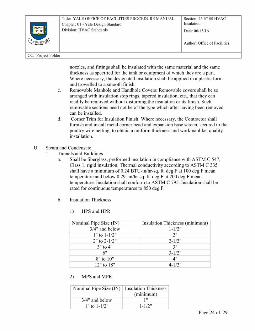
U. Steam and Condensate
1. Tunnels and Buildings
a. Shall be fiberglass, preformed insulation in compliance with ASTM C 547,
Class 1, rigid insulation. Thermal conductivity according to ASTM C 335
shall have a minimum of 0.24 BTU-in/hr-sq. ft. deg F at 100 deg F mean
temperature and below 0.29 -in/hr-sq. ft. deg F at 200 deg F mean
temperature. Insulation shall conform to ASTM C 795. Insulation shall be
rated for continuous temperatures to 850 deg F.
b. Insulation Thickness
1) HPS and HPR
Nominal Pipe Size (IN) Insulation Thickness (minimum)
3/4" and below 1-1/2"
1" to 1-1/2" 2"
2" to 2-1/2" 2-1/2"
3" to 4" 3"
6" 3-1/2"
8" to 10" 4"
12" to 18" 4-1/2"
2) MPS and MPR
Nominal Pipe Size (IN) Insulation Thickness
(minimum)
3/4" and below 1"
1" to 1-1/2" 1-1/2"
Title: YALE OFFICE OF FACILITIES PROCEDURE MANUAL
Chapter: 01 - Yale Design Standard
Division: HVAC Standards
Section: 23 07 00 HVAC
Insulation
Date: 06/15/16
Author: Office of Facilities
CC: Project Folder
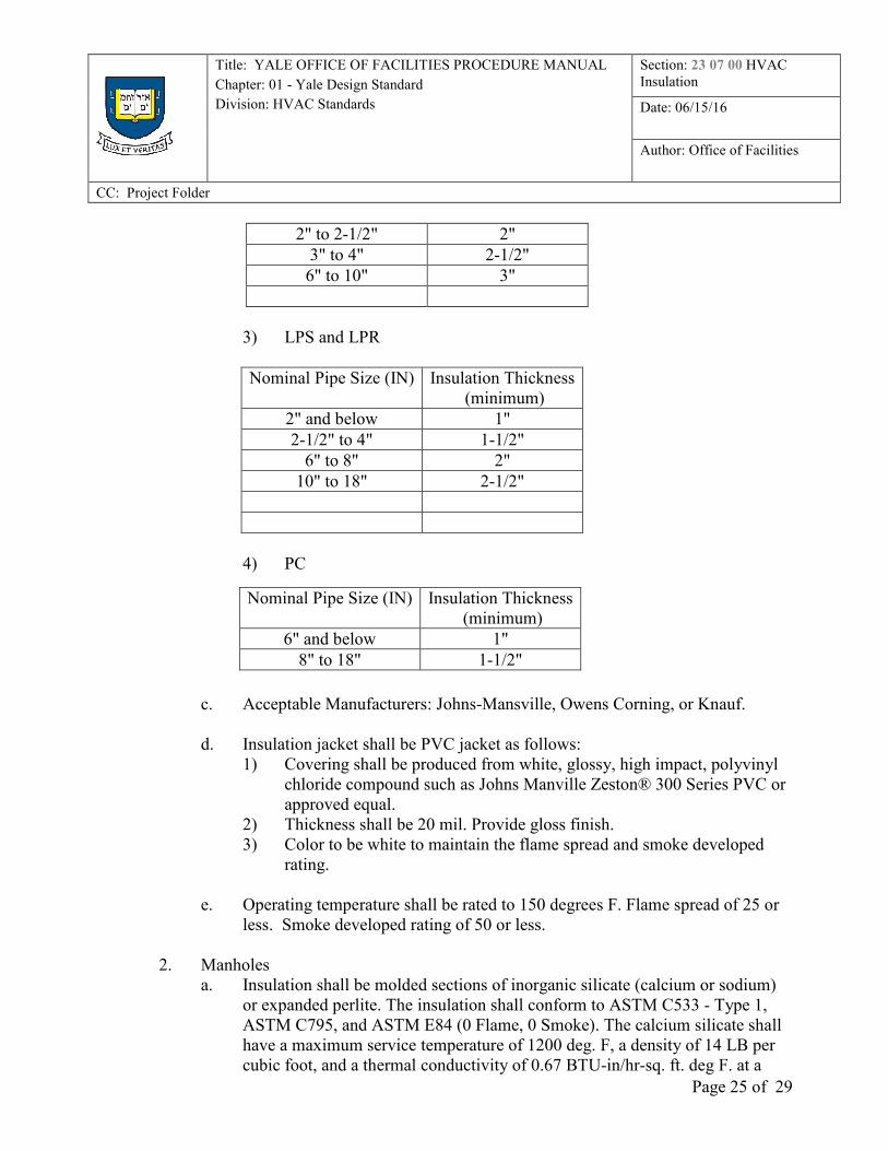
Page 25 of 29
2" to 2-1/2" 2"
3" to 4" 2-1/2"
6" to 10" 3"
3) LPS and LPR
Nominal Pipe Size (IN) Insulation Thickness
(minimum)
2" and below 1"
2-1/2" to 4" 1-1/2"
6" to 8" 2"
10" to 18" 2-1/2"
4) PC
c. Acceptable Manufacturers: Johns-Mansville, Owens Corning, or Knauf.
d. Insulation jacket shall be PVC jacket as follows:
1) Covering shall be produced from white, glossy, high impact, polyvinyl
chloride compound such as Johns Manville Zeston® 300 Series PVC or
approved equal.
2) Thickness shall be 20 mil. Provide gloss finish.
3) Color to be white to maintain the flame spread and smoke developed
rating.
e. Operating temperature shall be rated to 150 degrees F. Flame spread of 25 or
less. Smoke developed rating of 50 or less.
2. Manholes
a. Insulation shall be molded sections of inorganic silicate (calcium or sodium)
or expanded perlite. The insulation shall conform to ASTM C533 - Type 1,
ASTM C795, and ASTM E84 (0 Flame, 0 Smoke). The calcium silicate shall
have a maximum service temperature of 1200 deg. F, a density of 14 LB per
cubic foot, and a thermal conductivity of 0.67 BTU-in/hr-sq. ft. deg F. at a
Nominal Pipe Size (IN) Insulation Thickness
(minimum)
6" and below 1"
8" to 18" 1-1/2"
Title: YALE OFFICE OF FACILITIES PROCEDURE MANUAL
Chapter: 01 - Yale Design Standard
Division: HVAC Standards
Section: 23 07 00 HVAC
Insulation
Date: 06/15/16
Author: Office of Facilities
CC: Project Folder
Page 26 of 29
mean temperature of 700 degrees F per ASTM C335. Linear shrinkage shall
be less than 1%. The insulation shall be certified by the manufacturer not to
accelerate stress corrosion of stainless steel pipe and shall conform to ASTM
C795.
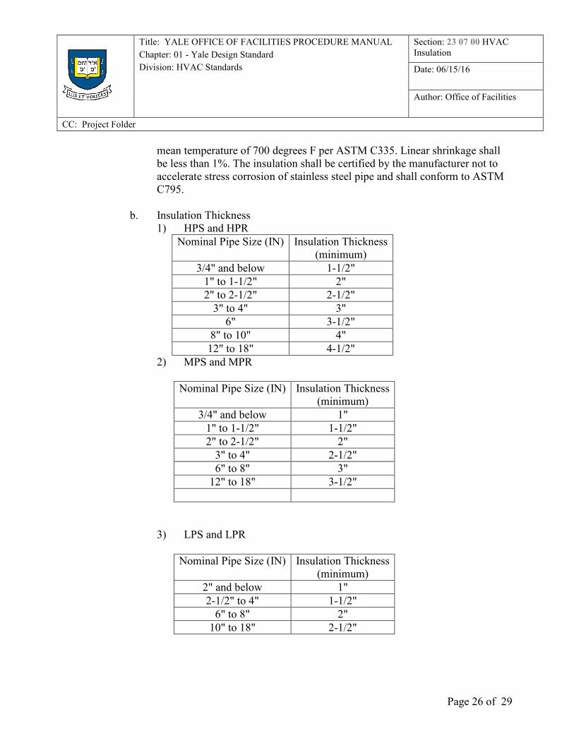
b. Insulation Thickness
1) HPS and HPR
Nominal Pipe Size (IN) Insulation Thickness
(minimum)
3/4" and below 1-1/2"
1" to 1-1/2" 2"
2" to 2-1/2" 2-1/2"
3" to 4" 3"
6" 3-1/2"
8" to 10" 4"
12" to 18" 4-1/2"
2) MPS and MPR
Nominal Pipe Size (IN) Insulation Thickness
(minimum)
3/4" and below 1"
1" to 1-1/2" 1-1/2"
2" to 2-1/2" 2"
3" to 4" 2-1/2"
6" to 8" 3"
12" to 18" 3-1/2"
3) LPS and LPR
Nominal Pipe Size (IN) Insulation Thickness
(minimum)
2" and below 1"
2-1/2" to 4" 1-1/2"
6" to 8" 2"
10" to 18" 2-1/2"
Title: YALE OFFICE OF FACILITIES PROCEDURE MANUAL
Chapter: 01 - Yale Design Standard
Division: HVAC Standards
Section: 23 07 00 HVAC
Insulation
Date: 06/15/16
Author: Office of Facilities
CC: Project Folder
Page 27 of 29
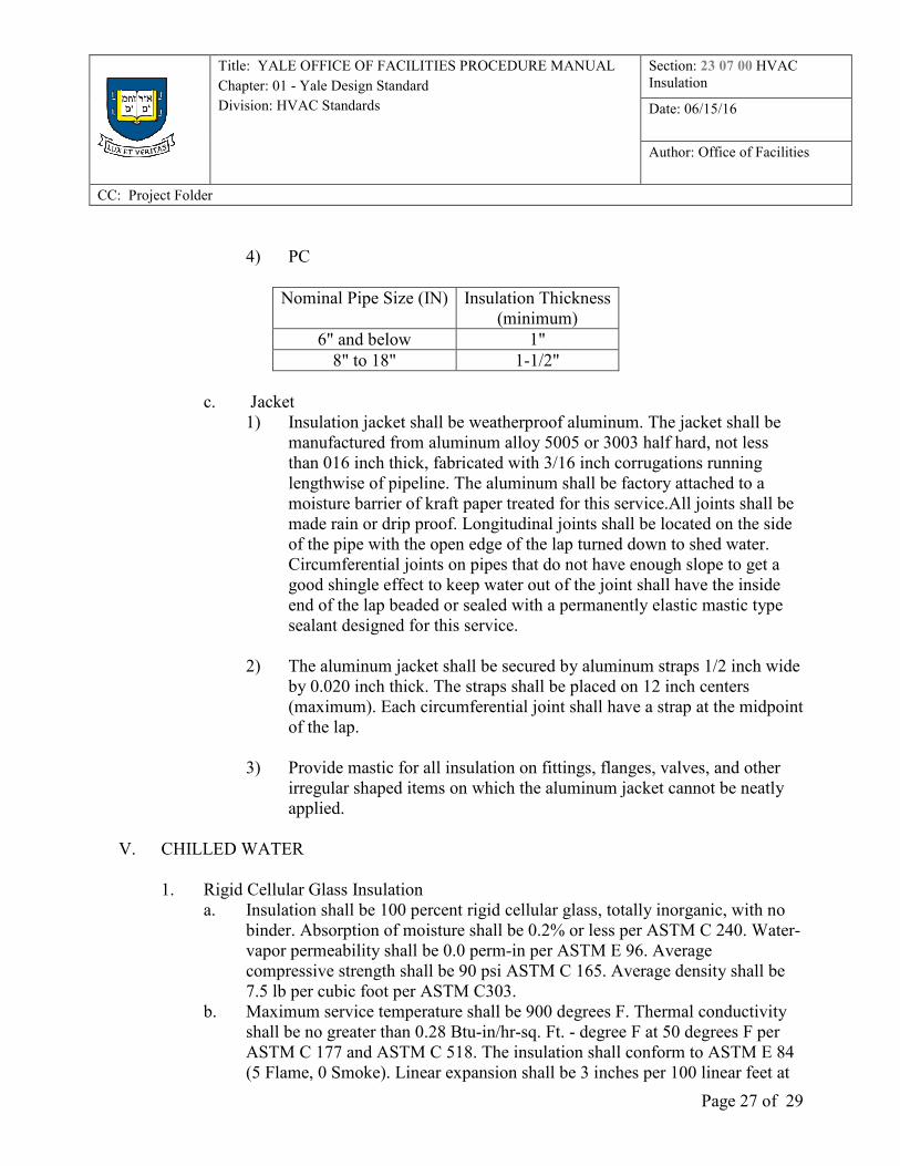
4) PC
Nominal Pipe Size (IN) Insulation Thickness
(minimum)
6" and below 1"
8" to 18" 1-1/2"
c. Jacket
1) Insulation jacket shall be weatherproof aluminum. The jacket shall be
manufactured from aluminum alloy 5005 or 3003 half hard, not less
than 016 inch thick, fabricated with 3/16 inch corrugations running
lengthwise of pipeline. The aluminum shall be factory attached to a
moisture barrier of kraft paper treated for this service.All joints shall be
made rain or drip proof. Longitudinal joints shall be located on the side
of the pipe with the open edge of the lap turned down to shed water.
Circumferential joints on pipes that do not have enough slope to get a
good shingle effect to keep water out of the joint shall have the inside
end of the lap beaded or sealed with a permanently elastic mastic type
sealant designed for this service.
2) The aluminum jacket shall be secured by aluminum straps 1/2 inch wide
by 0.020 inch thick. The straps shall be placed on 12 inch centers
(maximum). Each circumferential joint shall have a strap at the midpoint
of the lap.
3) Provide mastic for all insulation on fittings, flanges, valves, and other
irregular shaped items on which the aluminum jacket cannot be neatly
applied.
V. CHILLED WATER
1. Rigid Cellular Glass Insulation
a. Insulation shall be 100 percent rigid cellular glass, totally inorganic, with no
binder. Absorption of moisture shall be 0.2% or less per ASTM C 240. Water-
vapor permeability shall be 0.0 perm-in per ASTM E 96. Average
compressive strength shall be 90 psi ASTM C 165. Average density shall be
7.5 lb per cubic foot per ASTM C303.
b. Maximum service temperature shall be 900 degrees F. Thermal conductivity
shall be no greater than 0.28 Btu-in/hr-sq. Ft. - degree F at 50 degrees F per
ASTM C 177 and ASTM C 518. The insulation shall conform to ASTM E 84
(5 Flame, 0 Smoke). Linear expansion shall be 3 inches per 100 linear feet at
Title: YALE OFFICE OF FACILITIES PROCEDURE MANUAL
Chapter: 01 - Yale Design Standard
Division: HVAC Standards
Section: 23 07 00 HVAC
Insulation
Date: 06/15/16
Author: Office of Facilities
CC: Project Folder
Page 28 of 29
600 degrees F. Insulation shall be fabricated in half sections wherever
possible. For large diameter piping where half sections are not practical,
curved side wall segments are preferred.
c. Provide insulation from one of the following manufacturers and product trade
names:
1) Pittsburgh Corning FOAMGLAS
2) 800 Presque Isle Drive Pittsburgh, PA 15239
3) Phone Number: (800) 359-8433
d. Pipe surfaces shall be clean and dry prior to insulating.
e. Provide PITTSEAL 727 sealant to prevent water vapor entry. Provide
PITTCOTE 300 coating to fill the surface cells. Ensure that all pipe surfaces
are covered by insulation and that the insulation is sealed and coated so that no
condensation takes place on the pipe surface.
f. Insulation shall be temporarily held in place with stainless steel wire or fiber
reinforced tape overlapped a minimum of 6 inches prior to the insulation
finish being installed. The tape and/or wire may remain on the insulation
beneath the insulation finish.
g. Thickness shall be per manufacturer's recommendations. For tunnels and
manholes where steam or condensate piping is present, ambient conditions
shall be selected for 120 degrees F and 90 percent relative humidity.
h. Insulation jacket shall be PVC jacket as follows:
1) Covering shall be produced from white, glossy, high impact, polyvinyl
chloride compound such as Johns Manville Zeston® 300 Series PVC or
approved equal.
2) Thickness shall be 20 mil. Provide gloss finish.
3) Color to be white to maintain the flame spread and smoke developed
rating.
4) Operating temperature shall be rated to 150 degrees F. Flame spread of
25 or less. Smoke developed rating of 50 or less.
W. RE-USABLE BLANKETS FOR VALVES
1. Provide re-usable blankets for pressure regulating valves.
2. General
a. Insulating material shall be tailor-made removable/reusable blankets. The
blankets shall be made with a high temperature fiberglass mat without the use
of chemical binders and suitable for temperatures up to 1200 degrees F.
b. All blanket and covers shall be constructed and designed to permit a heat of no
more than 92 Btu/sq. ft./hour and a surface temperature of not more than 135
degrees F. in still air at an ambient temperature of 80 degrees F. The minimum
blanket insulation thicknesses shall be as follows:
1) Operating Temperature of 130 to 300 degrees F: 1" thick
Title: YALE OFFICE OF FACILITIES PROCEDURE MANUAL
Chapter: 01 - Yale Design Standard
Division: HVAC Standards
Section: 23 07 00 HVAC
Insulation
Date: 06/15/16
Author: Office of Facilities
CC: Project Folder
Page 29 of 29
2) Operating Temperature of 301 to 400 degrees F: 2" thick
3) Operating Temperature of 401 to 500 degrees F: 3" thick
4) Operating Temperature of 501 to 800 degrees F: 4" thick
5) Operating Temperature of 801 to 1000 degrees F: 6" thick
c. Single layer blanket construction may be used for metal temperatures up to
600 degrees F. For metal temperatures over 600 degrees F., double layer
construction must be used. The joints for double construction between
blankets of the inner layer and those of the outer layer shall be offset from one
another.
d. The inner liner material for hot surface temperatures up to 500 degrees F. shall
be silicone coated glass cloth, 32 ounce. For hot surface temperatures between
500 and 1000 degrees F., the blanket insulation material shall be enclosed on
all sides with a knitted wire mesh. The knitted wire mesh shall be 304
stainless steel wire, 0.11" (11 mils) knitted into a tubular fabric using a mesh
size of 60 density.
e. The exterior jacket material shall be silicone glass cloth 32 ounce.
f. All blankets shall be quilted at frequent intervals with quilting fasteners.
g. The blankets shall be made and designed to fit tightly around the outside
diameters of the flanges and valves, leaving no gaps when laced. Each blanket
shall be constructed with 16 gauge stainless steel wire draw strings that pass
through hog rings and are spaced 3/4 inch apart. All mating edges of adjacent
blankets shall be fitted with blanket hooks, spaced approximately 6 inches on
centers or as required to provide securement for the stainless steel tie wire that
are used to lace adjacent blankets together.
h. Where blankets are provided for valves, the cover shall cover the body but not
the valve bonnet.