Embed Size (px)
Citation preview

Fort Rouge Leisure Centre Section 26 05 01 HVAC Upgrades – Phase 2 Page 1 of 8 Bid Opportunity No. 190-2013 March 2013
COMMON WORK RESULTS - ELECTRICAL
Part 1 General
1.1 REFERENCES
.1 Canadian Standards Association (CSA International)
.1 CSA C22.1-06, Canadian Electrical Code, Part 1 (20th Edition), Safety Standard for Electrical Installations.
.2 CSA C22.2.
.3 CAN/CSA-C22.3 No. 1, Overhead Systems.
.4 CAN3-C235-83(R2000), Preferred Voltage Levels for AC Systems, 0 to 50,000 V.
.2 Electrical and Electronic Manufacturer's Association of Canada (EEMAC)
.1 EEMAC 2Y-1-1958, Light Gray Colour for Indoor Switch Gear.
.3 Institute of Electrical and Electronics (IEEE)/National Electrical Safety Code Product Line (NESC)
.1 IEEE SP1122-2000, The Authoritative Dictionary of IEEE Standards Terms, 7th Edition.
1.2 DEFINITIONS
.1 Electrical and electronic terms: unless otherwise specified or indicated, terms used in these specifications, and on drawings, are those defined by IEEE SP1122.
1.3 DESIGN REQUIREMENTS
.1 Operating voltages: to CAN3-C235.
.2 Motors, electric heating, control and distribution devices and equipment to operate satisfactorily at 60 Hz within normal operating limits established by above standard.
.1 Equipment to operate in extreme operating conditions established in above standard without damage to equipment.
.3 Language operating requirements: provide identification nameplates and labels for control items in English.
.4 The contractor shall be required to obtain a complete FAS VI report for the FAS including the FAS Sprinkler system. A copy of these reports shall be left on site at the main FAS panel as well as a complete FAS device list (with addresses). Soft copies of these reports are required. As built drawings of a floor plan with all of the FAS devices, indicating approx. device location and addressable address shall be provided. The contractor shall supply as built drawings of all of the FAS network loops. The contractor shall supply as built drawings of sprinkler system showing approx. location of all sprinkler devices and zoning.
Fort Rouge Leisure Centre Section 26 05 01 HVAC Upgrades – Phase 2 Page 2 of 8 Bid Opportunity No. 190-2013 March 2013
COMMON WORK RESULTS - ELECTRICAL
1.4 SUBMITTALS
.1 Submittals: in accordance with Section 01 33 00 - Submittal Procedures.
.2 Submit for review single line electrical diagrams under plexiglass and locate at main service.
.1 Electrical distribution system in main electrical room.
.3 Submit for review fire alarm riser diagram, plan and zoning of building under plexiglass at fire alarm control panel and annunciator.
.4 Shop drawings:
.1 Submit wiring diagrams and installation details of equipment indicating proposed location, layout and arrangement, control panels, accessories, piping, ductwork, and other items that must be shown to ensure co-ordinated installation.
.2 Identify on wiring diagrams circuit terminals and indicate internal wiring for each item of equipment and interconnection between each item of equipment.
.3 Indicate of drawings clearances for operation, maintenance, and replacement of operating equipment devices.
.4 Submit and product data to Contract Administrator. Quantities as required.
.5 If changes are required, notify Contract Administrator of these changes before they are made.
.5 Quality Control: .
.1 Provide CSA certified equipment and material. Where CSA certified equipment and material is not available, submit such equipment and material to authority having jurisdiction for special approval before delivery to site.
.2 Submit test results of installed electrical systems and instrumentation.
.3 Permits and fees: in accordance with General Conditions of contract.
.4 Submit, upon completion of Work, load balance report as described in PART 3 - LOAD BALANCE.
.5 Submit certificate of acceptance from authority having jurisdiction upon completion of Work to Contract Administrator.
.6 Manufacturer's Field Reports: submit to Contract Administrator manufacturer's written report, within 3 days of review, verifying compliance of Work and electrical system and instrumentation testing, as described in PART 3 - FIELD QUALITY CONTROL.
1.5 QUALITY ASSURANCE
.1 Qualifications: electrical Work to be carried out by qualified, licensed electricians or apprentices in accordance with authorities having jurisdiction as per the conditions of Provincial Acts respecting manpower vocational training and qualification.
.1 Employees registered in provincial apprentices program: permitted, under direct supervision of qualified licensed electrician, to perform specific tasks.

Fort Rouge Leisure Centre Section 26 05 01 HVAC Upgrades – Phase 2 Page 3 of 8 Bid Opportunity No. 190-2013 March 2013
COMMON WORK RESULTS - ELECTRICAL
.2 Permitted activities: determined based on training level attained and demonstration of ability to perform specific duties.
.2 Site Meetings:
.1 In accordance with Construction Progress Schedule - Bar (GANTT) Charts.
1.6 DELIVERY, STORAGE AND HANDLING
.1 Construction/Demolition Waste Management and Disposal: separate waste materials for reuse and recycling.
1.7 SYSTEM STARTUP
.1 Instruct Operating Personnel in operation, care and maintenance of systems, system equipment and components.
.2 Arrange and pay for services of manufacturer's factory service engineer to supervise start-up of installation, check, adjust, balance and calibrate components and instruct operating personnel.
.3 Provide these services for such period, and for as many visits as necessary to put equipment in operation, and ensure that operating personnel are conversant will aspects of its care and operation.
1.8 OPERATING INSTRUCTIONS
.1 Provide for each system and principal item of equipment as specified in technical sections for use by operation and maintenance personnel.
.2 Operating instructions to include following:
.1 Wiring diagrams, control diagrams, and control sequence for each principal system and item of equipment.
.2 Start up, proper adjustment, operating, lubrication, and shutdown procedures.
.3 Safety precautions.
.4 Procedures to be followed in event of equipment failure.
.5 Other items of instruction as recommended by manufacturer of each system or item of equipment.
.3 Print or engrave operating instructions and frame under glass or in approved laminated plastic.
.4 Post instructions where directed.
.5 For operating instructions exposed to weather, provide weather-resistant materials or weatherproof enclosures.
.6 Ensure operating instructions will not fade when exposed to sunlight and are secured to prevent easy removal or peeling.
Fort Rouge Leisure Centre Section 26 05 01 HVAC Upgrades – Phase 2 Page 4 of 8 Bid Opportunity No. 190-2013 March 2013
COMMON WORK RESULTS - ELECTRICAL
1.9 SEPARATE PRICING
.1 The contract shall require the electrical be broken into the following separate price items for electrical:
.1 SP-1 Fire Alarm System Upgrade
.2 SP-2 Upgrade to the Emergency Lighting System.
.3 SP-3 Upgrade to the Gym and Weight Room Lighting.
.4 SP-4 Electrical required for mechanical system upgrade including all upgrades in the mezzanine.
Part 2 Products
2.1 MATERIALS AND EQUIPMENT
.1 Material and equipment to be CSA certified. Where CSA certified material and equipment is not available, obtain special approval from authority having jurisdiction before delivery to site and submit such approval as described in PART 1 - SUBMITTALS.
.2 Factory assemble control panels and component assemblies.
2.2 ELECTRIC MOTORS, EQUIPMENT AND CONTROLS
.1 Verify installation and co-ordination responsibilities related to motors, equipment and controls, as indicated.
.2 Control wiring and conduit: in accordance with Section 26 29 03 - Control Devices except for conduit, wiring and connections below 50 V which are related to control systems specified in mechanical sections and as shown on mechanical drawings.
2.3 WARNING SIGNS
.1 Warning Signs: in accordance with requirements of authority having jurisdiction and Contract Administrator.
.2 decal signs, minimum size 175 x 250 mm.
2.4 WIRING TERMINATIONS
.1 Ensure lugs, terminals, screws used for termination of wiring are suitable for either copper or aluminium conductors.
2.5 EQUIPMENT IDENTIFICATION
.1 Identify electrical equipment with nameplates and labels as follows:
.1 Nameplates: lamicoid 3 mm matt white finish face, black core, lettering accurately aligned and engraved into core mechanically attached with self tapping screws.
Fort Rouge Leisure Centre Section 26 05 01 HVAC Upgrades – Phase 2 Page 5 of 8 Bid Opportunity No. 190-2013 March 2013
COMMON WORK RESULTS - ELECTRICAL
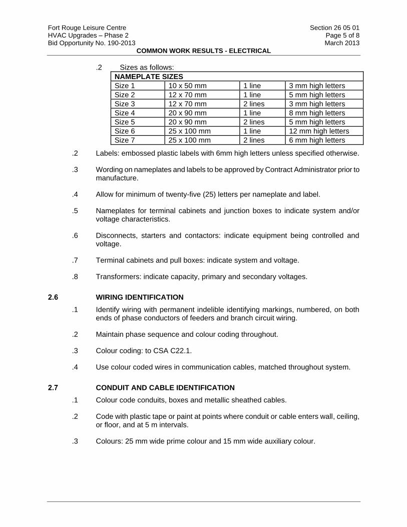
.2 Sizes as follows:
NAMEPLATE SIZES
Size 1 10 x 50 mm 1 line 3 mm high letters
Size 2 12 x 70 mm 1 line 5 mm high letters
Size 3 12 x 70 mm 2 lines 3 mm high letters
Size 4 20 x 90 mm 1 line 8 mm high letters
Size 5 20 x 90 mm 2 lines 5 mm high letters
Size 6 25 x 100 mm 1 line 12 mm high letters
Size 7 25 x 100 mm 2 lines 6 mm high letters
.2 Labels: embossed plastic labels with 6mm high letters unless specified otherwise.
.3 Wording on nameplates and labels to be approved by Contract Administrator prior to manufacture.
.4 Allow for minimum of twenty-five (25) letters per nameplate and label.
.5 Nameplates for terminal cabinets and junction boxes to indicate system and/or voltage characteristics.
.6 Disconnects, starters and contactors: indicate equipment being controlled and voltage.
.7 Terminal cabinets and pull boxes: indicate system and voltage.
.8 Transformers: indicate capacity, primary and secondary voltages.
2.6 WIRING IDENTIFICATION
.1 Identify wiring with permanent indelible identifying markings, numbered, on both ends of phase conductors of feeders and branch circuit wiring.
.2 Maintain phase sequence and colour coding throughout.
.3 Colour coding: to CSA C22.1.
.4 Use colour coded wires in communication cables, matched throughout system.
2.7 CONDUIT AND CABLE IDENTIFICATION
.1 Colour code conduits, boxes and metallic sheathed cables.
.2 Code with plastic tape or paint at points where conduit or cable enters wall, ceiling, or floor, and at 5 m intervals.
.3 Colours: 25 mm wide prime colour and 15 mm wide auxiliary colour.

Fort Rouge Leisure Centre Section 26 05 01 HVAC Upgrades – Phase 2 Page 6 of 8 Bid Opportunity No. 190-2013 March 2013
COMMON WORK RESULTS - ELECTRICAL
Prime Auxiliary
up to 250 V Yellow
up to 600 V Yellow Green
up to 5 kV Yellow Blue
up to 15 kV Yellow Red
Telephone Green
Other Communication Systems Green Blue
Fire Alarm Red
Emergency Voice Red Blue
Other Security Systems Red Yellow
2.8 FINISHES
.1 Shop finish metal enclosure surfaces by application of rust resistant primer inside and outside, and at least two coats of finish enamel.
.1 Paint outdoor electrical equipment "equipment green" finish.
.2 Paint indoor switchgear and distribution enclosures light grey to EEMAC 2Y-1.
Part 3 Execution
3.1 INSTALLATION
.1 Do complete installation in accordance with CSA C22.1 except where specified otherwise.
.2 Do overhead and underground systems in accordance with CSA C22.3 No.1 except where specified otherwise.
3.2 NAMEPLATES AND LABELS
.1 Ensure manufacturer's nameplates, CSA labels and identification nameplates are visible and legible after equipment is installed.
3.3 CONDUIT AND CABLE INSTALLATION
.1 Install conduit and sleeves prior to pouring of concrete.
.1 Sleeves through concrete: schedule 40 plastic, sized for free passage of conduit, and protruding 50 mm.
.2 If plastic sleeves are used in fire rated walls or floors, remove before conduit installation.
.3 Install cables, conduits and fittings embedded or plastered over, close to building structure so furring can be kept to minimum.

Fort Rouge Leisure Centre Section 26 05 01 HVAC Upgrades – Phase 2 Page 7 of 8 Bid Opportunity No. 190-2013 March 2013
COMMON WORK RESULTS - ELECTRICAL
3.4 LOCATION OF OUTLETS
.1 Locate outlets in accordance with Section 26 05 32 - Outlet Boxes, Conduit Boxes and Fittings.
.2 Do not install outlets back-to-back in wall; allow minimum 150 mm horizontal clearance between boxes.
.3 Change location of outlets at no extra cost or credit, providing distance does not exceed 3000 mm, and information is given before installation.
.4 Locate light switches on latch side of doors.
.1 Locate disconnect devices in mechanical and elevator machine rooms on latch side of floor.
3.5 MOUNTING HEIGHTS
.1 Mounting height of equipment is from finished floor to centreline of equipment unless specified or indicated otherwise.
.2 If mounting height of equipment is not specified or indicated, verify before proceeding with installation. Install electrical equipment at following heights unless indicated otherwise.
.1 Local switches: 1200 mm.
.2 Wall receptacles: .1 General: 300 mm. .2 Above top of continuous baseboard heater: 200 mm. .3 Above top of counters or counter splash backs: 175 mm. .4 In mechanical rooms: 1400 mm.
.3 Panelboards: as required by Code or as indicated.
.4 Fire alarm stations: 1200 mm.
.5 Fire alarm bells/strobes: 2100 mm.
3.6 CO-ORDINATION OF PROTECTIVE DEVICES
.1 Ensure circuit protective devices such as overcurrent trips, relays and fuses are installed to required values and settings.Verify co-ordination with upstream devices.
3.7 FIELD QUALITY CONTROL
.1 Load Balance:
.1 Measure phase current to panelboards with normal loads (lighting) operating at time of acceptance; adjust branch circuit connections as required to obtain best balance of current between phases and record changes.
.2 Measure phase voltages at loads and adjust transformer taps to within 2% of rated voltage of equipment.

Fort Rouge Leisure Centre Section 26 05 01 HVAC Upgrades – Phase 2 Page 8 of 8 Bid Opportunity No. 190-2013 March 2013
COMMON WORK RESULTS - ELECTRICAL
.3 Provide upon completion of work, load balance report as directed in PART 1 - SUBMITTALS: phase and neutral currents on panelboards, dry-core transformers and motor control centres, operating under normal load, as well as hour and date on which each load was measured, and voltage at time of test.
.2 Conduct following tests:
.1 Power distribution system including phasing, voltage, grounding and load balancing.
.2 Circuits originating from branch distribution panels.
.3 Lighting and its control.
.4 Motors, heaters and associated control equipment including sequenced operation of systems where applicable.
.5 Systems: fire alarm system, Security System, PA system, communications.
.6 Insulation resistance testing:
.1 Megger circuits, feeders and equipment up to 350 V with a 500 V instrument.
.2 Megger 350-600 V circuits, feeders and equipment with a 1000 V instrument.
.3 Check resistance to ground before energizing.
.3 Carry out tests in presence of Departmental Representative.
.4 Provide instruments, meters, equipment and personnel required to conduct tests during and at conclusion of project.
.5 Manufacturer's Field Services:
.1 Obtain written report from manufacturer verifying compliance of Work, in handling, installing, applying, protecting and cleaning of product and submit Manufacturer's Field Reports as described in PART 1 - SUBMITTALS.
.2 Provide manufacturer's field services consisting of product use recommendations and periodic site visits for inspection of product installation in accordance with manufacturer's instructions.
.3 Schedule site visits, to review Work, as directed in PART 1 - QUALITY ASSURANCE.
3.8 CLEANING
.1 Clean and touch up surfaces of shop-painted equipment scratched or marred during shipment or installation, to match original paint.
.2 Clean and prime exposed non-galvanized hangers, racks and fastenings to prevent rusting.
END OF SECTION

Fort Rouge Leisure Centre Section 26 05 02 HVAC Upgrades – Phase 2 Page 1 of 2 Bid Opportunity No. 190-2013 March 2013
MECHANICAL EQUIPMENT CONNECTIONS
Part 1 General
1.1 RELATED WORK
.1 Mechanical Specifications Division 22 and 23
.2 Common Work Results Section 260501
.3 Wires and Cables (0-1000 V) Section 260521
.4 Outlet Boxes, Conduit Boxes and Fittings Section 260532
.5 Conduits, Conduit Fastenings and Conduit Fittings Section 260534
.6 Disconnect Switches - Fused and Non-Fused Section 262823
.7 Motor Starters to 600 V Section 262910
.8 Variable Speed Drives Section 262923
1.2 SYSTEM DESCRIPTION
.1 Provide complete electrical power and control connections for mechanical equipment, except as noted herein, or as noted on the drawings.
Part 2 Products 2.1 MATERIALS .1 Include motor starters, lockable disconnects, conduit, wire, fittings, interlocks, outlet boxes, junction
boxes, and all associated equipment required to provide power wiring for mechanical equipment, unless otherwise indicated.
.2 Include pushbutton stations, motor protective switches, interlocks, conduit, wire, devices, and fittings
required to provide control wiring for mechanical equipment, except for temperature/humidity control systems.
.3 Unless otherwise noted, motors and control devices shall be supplied by Division 22 and 23. Motor
horsepower ratings shall be as shown in the Division 22 and 23 specifications. Motor voltage and phase ratings shall be as shown on the Division 26 and 28 drawings.
2.2 EXTERIOR EQUIPMENT .1 All equipment, mounted on the exterior of the building, shall be weatherproof.
Part 3 Execution 3.1 POWER WIRING
.1 Install power feeders, starters, lockable disconnects, and associated equipment and make
connections to all mechanical equipment. .2 Install branch circuit wiring for mechanical system control panels, time clocks, and control
transformers. .3 Install main power feeders to starter/control panels furnished by Division 22 and 23. Install branch
wiring from starter/control panels to controlled equipment such as motors, electric coils, etc. .4 Conduit, wire, devices and fittings required to wire and connect low voltage control systems, shall be
supplied and installed by the trade supplying the temperature control system. Control wiring shall be installed in conduit.
.5 Wire and connect electrical interlocks for starters supplied by Division 22 and 23.
Fort Rouge Leisure Centre Section 26 05 02 HVAC Upgrades – Phase 2 Page 2 of 2 Bid Opportunity No. 190-2013 March 2013
MECHANICAL EQUIPMENT CONNECTIONS
.6 Wire and connect hi-limit cutouts for remotely mounted electric heating coils provided by Division 22
and 23. .7 Wire and connect thermistor control devices, built-in to large motors, to motor starters, as per wiring
diagrams provided by Division 22 and 23.
3.2 CONTROLS
.1 Install all electrical controls, except low voltage temperature controls, unless otherwise noted herein. Controls which have both electrical and mechanical connections shall be installed by the trade supplying the control.
.2 Wire and connect float switches, pressure switches, alternators, alarms, etc. for sump pumps,
domestic hot water re-circulating pumps, and booster pumps. .3 Conduit, wire, devices and fittings required to wire and connect low voltage controls, which are an
integral part of a packaged unit, shall be supplied by the trade supplying the packaged unit, unless otherwise indicated. Control wiring shall be installed in conduit.
.4 Wire and connect electrical interlocks for starters supplied by Division 22 and 23. .5 Wire and connect hi-limit cutouts for remotely mounted electric heating coils provided by Division 22
and 23. .6 Wire and connect thermistor control devices, built-in to large motors, to motor starters, as per wiring
diagrams provided by Division 22 and 23. .7 Wire and Connect air Handling units to Fire Alarm Control Panel for Fan shutdown. Clearly indicate
on As-Built Drawings and Fire Alarm Graphical Drawing Unit wired to FACP for Fan shutdown.
3.3 CO-ORDINATION
.1 Refer to mechanical drawings for the exact location of motor control devices, and other mechanical equipment requiring an electrical connection.
.2 Obtain full information from Division 22 and 23, regarding wiring controls, overload heaters,
equipment ratings and over-current protection. Notify the Division 22 and 23, at once, if any information provided is incorrect or unsatisfactory.
.3 Refer to Division 22 and 23 specifications for any further electrical requirements. .4 Review both electrical and mechanical drawings and specifications and coordinate all controls with
Mechanical Subtrades through General Contractor. Report all discrepancies to contract administrator before close of bids. No additional money will be justified for assumptions made on any duplication of information.
END OF SECTION
Fort Rouge Leisure Centre Section 26 05 20 HVAC Upgrades – Phase 2 Page 1 of 1 Bid Opportunity No. 190-2013 March 2013
WIRE BOX CONNECTORS – 0 - 1000 V
Part 1 General
1.1 SECTION INCLUDES
.1 Materials and installation for wire and box connectors.
1.2 REFERENCES
.1 Canadian Standards Association (CSA International)
.1 CAN/CSA-C22.2No.18-98, Outlet Boxes, Conduit Boxes, Fittings and Associated Hardware.
.2 CSA C22.2No.65-93(R1999), Wire Connectors.
.2 Electrical and Electronic Manufacturers' Association of Canada (EEMAC)
.1 EEMAC 1Y-2, 1961 Bushing Stud Connectors and Aluminum Adapters (1200 Ampere Maximum Rating).
.3 National Electrical Manufacturers Association (NEMA)
Part 2 Products
2.1 MATERIALS
.1 Pressure type wire connectors to: CSA C22.2 No.65, with current carrying parts of copper or copper alloy sized to fit copper or aluminum conductors as required.
.2 Fixture type splicing connectors to: CSA C22.2 No.65, with current carrying parts of copper or copper alloy sized to fit copper conductors 10 AWG or less.
.3 Clamps or connectors for armoured cable, aluminum sheathed cable, flexible conduit, non-metallic sheathed cable as required to: CAN/CSA-C22.2 No.18.Execution
2.2 INSTALLATION
.1 Remove insulation carefully from ends of conductors and:
.1 Apply coat of zinc joint compound on aluminum conductors prior to installation of connectors.
.2 Install mechanical pressure type connectors and tighten screws with appropriate compression tool recommended by manufacturer. Installation shall meet secureness tests in accordance with CSA C22.2No.65.
.3 Install fixture type connectors and tighten. Replace insulating cap.
.4 Install bushing stud connectors in accordance with NEMA.
END OF SECTION
Fort Rouge Leisure Centre Section 26 05 21 HVAC Upgrades – Phase 2 Page 1 of 3 Bid Opportunity No. 190-2013 March 2013
WIRES AND CABLES (0-1000 V)
Part 1 General
1.1 RELATED SECTIONS
.1 Section 26 05 20 - Wire and Box Connectors - 0 - 1000 V.
1.2 REFERENCES
.1 CSA C22.2 No .0.3-96, Test Methods for Electrical Wires and Cables.
.2 CAN/CSA-C22.2 No. 131-M89(R1994), Type TECK 90 Cable.
1.3 PRODUCT DATA
.1 Submit product data in accordance with Section 01 33 00 - Submittal Procedures.
1.4 WASTE MANAGEMENT AND DISPOSAL
.1 Separate and recycle waste materials.
.2 Collect and separate plastic, paper packaging and corrugated cardboard in accordance with Waste Management Plan.
.3 Fold up metal banding, flatten and place in designated area for recycling.
Part 2 Products
2.1 BUILDING WIRES
.1 Conductors: stranded for 10 AWG and larger. Minimum size: 12 AWG.
.2 Copper conductors: size as indicated, with 1000 V insulation of chemically cross-linked thermosetting polyethylene material rated RW90.
.3 Aluminum conductors made of NUAL may be used only where clearly indicated on drawings.
2.2 TECK CABLE
.1 Cable: to CAN/CSA-C22.2 No. 131.
.2 Conductors:
.1 Grounding conductor: copper.
.2 Circuit conductors: copper, size as indicated.
.3 Aluminum conductors made of NUAL may be used only where clearly indicated on drawings.
.3 Insulation:
.1 Chemically cross-linked thermosetting polyethylene rated type RW90, 1000 V.
.4 Inner jacket: polyvinyl chloride material.
.5 Armour: interlocking galvanized steel or aluminum.
.6 Overall covering: polyvinyl chloride material.
Fort Rouge Leisure Centre Section 26 05 21 HVAC Upgrades – Phase 2 Page 2 of 3 Bid Opportunity No. 190-2013 March 2013
WIRES AND CABLES (0-1000 V)
.7 Fastenings:
.1 One hole steel straps to secure surface cables 50 mm and smaller. Two hole steel straps for cables larger than 50 mm.
.2 Channel type supports for two or more cables at 50 mm centers.
.3 Threaded rods: 6 mm dia. to support suspended channels.
.8 Connectors:
.1 Watertight approved for TECK cable. Explosion proof connectors shall be used in rated areas.
2.3 ARMOURED CABLES
.1 Conductors: insulated, copper, size as indicated. Aluminum conductors made of NUAL may be used only where clearly indicated on drawings.
.2 Type: AC90.
.3 Armour: interlocking type fabricated from galvanized steel or aluminum strip.
.4 Connectors: Teck90 Style.
2.4 ALUMINUM SHEATHED CABLE
.1 Conductors: copper, size as indicated.
.2 Insulation: type RA90 rated 1000 V.
.3 Sheath: aluminum applied to form continuous sheath.
.4 Fastenings for aluminum sheathed cable:
.1 One hole aluminum straps to secure surface cables 25 mm and smaller. Two hole steel straps for cables larger than 25 mm. Use aluminum strap only with single conductor cable.
.2 Channel type supports for two or more cables.
.3 Threaded rods: 6 mm dia. to support suspended channels.
2.5 CONTROL CABLES
.1 Low energy 300 V control cable: stranded annealed copper conductors sized as indicated. All cables shall be FT-4 rated and meet manufacturers requirements for the intended purpose. Cables shall be shielded as required. Cables for fire alarm systems shall be rated FA or FAS and meet the requirements of the fire alarm system manufacturer.
.2 600 V type: as above but with 600V insulation where required.
Part 3 Execution
3.1 INSTALLATION - General
.1 Install wiring as follows:
Fort Rouge Leisure Centre Section 26 05 21 HVAC Upgrades – Phase 2 Page 3 of 3 Bid Opportunity No. 190-2013 March 2013
WIRES AND CABLES (0-1000 V)
.1 In conduit systems in accordance with Section 26 05 34.
3.2 INSTALLATION OF BUILDING WIRES
.1 Install wiring as follows:
.1 In conduit systems in accordance with Section 26 05 34.
.2 Where wiring is required to be run in public areas it shall be run in metallic surface wiremold. All surface raceway shall be painted to match surroundings. Surface Raceway shall be approved by Contract Administrator at all locations prior to installation.
3.3 INSTALLATION OF TECK CABLE 0 -1000 V
.1 Install cables.
.1 Group cables wherever possible on channels.
.2 Terminate cables in accordance with Section 26 05 20- Wire and Box Connectors - 0 - 1000 V.
3.4 INSTALLATION OF ARMOURED CABLES
.1 Group cables wherever possible.
.2 Terminate cables in accordance with Section 26 05 20 - Wire and Box Connectors - 0 - 1000 V.
3.5 INSTALLATION OF ALUMINUM SHEATHED CABLE
.1 Group cables wherever possible on channels.
.2 Terminate cables in accordance with Section 26 05 20- Wire and Box Connectors - 0-1000 V.
3.6 INSTALLATION OF CONTROL CABLES
.1 Install control cables in conduit.
.2 Ground control cable shield as required for application
3.7 INSTALLATION OF NON-METALLIC SHEATHED CABLE
.1 Install cables.
.2 Install straps and box connectors to cables as required.
END OF SECTION

Fort Rouge Leisure Centre Section 26 05 31 HVAC Upgrades – Phase 2 Page 1 of 2 Bid Opportunity No. 190-2013 March 2013
SPLITTERS, JUNCTION, PULL BOXES AND CABINETS
Part 1 0BGeneral
1.1 3BSHOP DRAWINGS AND PRODUCT DATA
.1 11BSubmit shop drawings and product data for cabinets in accordance with Section 01 33 00 - Submittal Procedures.
1.2 4BWASTE MANAGEMENT AND DISPOSAL
.1 12BCollect and separate plastic, paper packaging and corrugated cardboard in accordance with Waste Management Plan.
.2 13BFold up metal banding, flatten and place in designated area for recycling.
Part 2 1BProducts
2.1 5BSPLITTERS
.1 14BSheet metal enclosure, welded corners and formed hinged cover suitable for locking in closed position.
.2 15BConnection bars to match required size and number of incoming and outgoing conductors as indicated.
.3 16BAt least three spare terminals on each set of lugs in splitters 400 A or less.
2.2 6BJUNCTION AND PULL BOXES
.1 17BWelded steel construction with screw-on flat covers for surface mounting.
.2 18BCovers with 25 mm minimum extension all around, for flush-mounted pull and junction boxes.
2.3 7BCABINETS
.1 19BType E: sheet steel, hinged door and return flange overlapping sides, handle, lock and catch, for surface mounting.
.2 20BType T: sheet steel cabinet, with hinged door, latch, lock, 2 keys, containing sheet steel backboard for surface or flush mounting as required.
.3 21BAll cabinets shall be sprinklerproof
Part 3 2BExecution
3.1 8BSPLITTER INSTALLATION
.1 22BInstall splitters and mount plumb, true and square to the building lines.
.2 23BExtend splitters full length of equipment arrangement except where indicated otherwise.

Fort Rouge Leisure Centre Section 26 05 31 HVAC Upgrades – Phase 2 Page 2 of 2 Bid Opportunity No. 190-2013 March 2013
SPLITTERS, JUNCTION, PULL BOXES AND CABINETS
3.2 9BJUNCTION, PULL BOXES AND CABINETS INSTALLATION
.1 24BInstall pull boxes in inconspicuous but accessible locations.
.2 25BMount cabinets with top not higher than 2 m above finished floor.
.3 26BInstall terminal block as required in Type T cabinets.
.4 27BOnly main junction and pull boxes are indicated. Install pull boxes so as not to exceed 30m of conduit run between pull boxes.
3.3 10BIDENTIFICATION
.1 28BProvide equipment identification in accordance with Section 26 05 01 - Common Work Results - Electrical.
.2 29BInstall size 2 identification labels indicating system name, voltage and phase.
END OF SECTION

Fort Rouge Leisure Centre Section 26 05 32 HVAC Upgrades – Phase 2 Page 1 of 2 Bid Opportunity No. 190-2013 March 2013
OUTLET BOXES, CONDUIT BOXES AND FITTINGS
Part 1 General
1.1 REFERENCES
.1 CSA C22.1-2006, Canadian Electrical Code, Part 1.
1.2 WASTE MANAGEMENT AND DISPOSAL
.1 Collect and separate plastic, paper packaging and corrugated cardboard in accordance with Waste Management Plan.
Part 2 Products
2.1 OUTLET AND CONDUIT BOXES GENERAL
.1 Size boxes in accordance with CSA C22.1.
.2 102 mm square or larger outlet boxes as required for special devices.
.3 Gang boxes where wiring devices are grouped.
.4 Blank cover plates for boxes without wiring devices.
.5 Combination boxes with barriers where outlets for more than one system are grouped.
2.2 SHEET STEEL OUTLET BOXES
.1 Electro-galvanized steel single and multi gang flush device boxes for flush installation, minimum size 76 x 50 x 38 mm or as indicated. 102 mm square outlet boxes when more than one conduit enters one side with extension and plaster rings as required.
.2 Electro-galvanized steel utility boxes for outlets connected to surface-mounted EMT conduit, minimum size 102 x 54 x 48 mm.
.3 102 mm square or octagonal outlet boxes for lighting fixture outlets.
.4 102 mm square outlet boxes with extension and plaster rings for flush mounting devices in finished tile walls.
2.3 MASONRY BOXES
.1 Electro-galvanized steel masonry single and multi gang boxes for devices flush mounted in exposed block walls.
2.4 CONCRETE BOXES
.1 Electro-glavanized sheet steel concrete type boxes for flush mount in concrete with matching extension and plaster rings as required.
Fort Rouge Leisure Centre Section 26 05 32 HVAC Upgrades – Phase 2 Page 2 of 2 Bid Opportunity No. 190-2013 March 2013
OUTLET BOXES, CONDUIT BOXES AND FITTINGS
2.5 FLOOR BOXES
.1 Concrete tight electro-galvanized sheet steel floor boxes with adjustable finishing rings to suit floor finish with brushed aluminum faceplates. Device mounting plate to accommodate short or long ear receptacles. Minimum depth: 28 mm for receptacles; 73 mm for communication equipment.
.2 Adjustable, watertight, concrete tight, cast floor boxes with openings drilled and tapped for 19 mm conduit. Minimum size: 73 mm deep.
2.6 CONDUIT BOXES
.1 Cast FS or FD boxes with factory-threaded hubs and mounting feet for surface wiring of switches and receptacle. This is only allowed in mechanical spaces.
2.7 OUTLET BOXES FOR NON-METALLIC SHEATHED CABLE
.1 Electro-galvanized, sectional, screw ganging steel boxes, minimum size 76 x 50 x 63 mm with two double clamps to take non-metallic sheathed cables.
2.8 FITTINGS - GENERAL
.1 Bushing and connectors with nylon insulated throats.
.2 Knock-out fillers to prevent entry of debris.
.3 Conduit outlet bodies for conduit up to 32 mm and pull boxes for larger conduits.
.4 Double locknuts and insulated bushings on sheet metal boxes.
Part 3 Execution
3.1 INSTALLATION
.1 Support boxes independently of connecting conduits.
.2 Fill boxes with paper, sponges or foam or similar approved material to prevent entry of debris during construction. Remove upon completion of work.
.3 For flush installations mount outlets flush with finished wall using plaster rings to permit wall finish to come within 6 mm of opening.
.4 Provide correct size of openings in boxes for conduit, mineral insulated and armoured cable connections. Reducing washers are not allowed.
END OF SECTION
Fort Rouge Leisure Centre Section 26 05 34 HVAC Upgrades – Phase 2 Page 1 of 4 Bid Opportunity No. 190-2013 March 2013
CONDUITS, CONDUIT FASTENINGS AND CONDUIT FITTINGS
Part 1 General
1.1 REFERENCES
.1 Canadian Standards Association (CSA)
.1 CAN/CSA C22.2 No. 18-98, Outlet Boxes, Conduit Boxes, and Fittings and Associated Hardware.
.2 CSA C22.2 No. 45-M1981(R1992), Rigid Metal Conduit.
.3 CSA C22.2 No. 56-1977(R1999), Flexible Metal Conduit and Liquid-Tight Flexible Metal Conduit.
.4 CSA C22.2 No. 83-M1985(R1999), Electrical Metallic Tubing.
.5 CSA C22.2 No. 211.2-M1984(R1999), Rigid PVC (Unplasticized) Conduit.
.6 CAN/CSA C22.2 No. 227.3-M91(R1999), Flexible Nonmetallic Tubing.
1.2 WASTE MANAGEMENT AND DISPOSAL
.1 Place materials defined as hazardous or toxic waste in designated containers.
.2 Ensure emptied containers are sealed and stored safely for disposal away from children.
.3 Collect and separate plastic, paper packaging and corrugated cardboard in accordance with Waste Management Plan.
Part 2 Products
2.1 CONDUITS
.1 Rigid metal conduit: to CSA C22.2 No. 45, galvanized steel threaded.
.2 Electrical metallic tubing (EMT): to CSA C22.2 No. 83, with couplings.
.3 Rigid pvc conduit: to CSA C22.2 No. 211.2.
.4 Flexible metal conduit: to CSA C22.2 No. 56, liquid-tight flexible metal.
2.2 CONDUIT FASTENINGS
.1 One hole steel straps to secure surface conduits 50 mm and smaller. Two hole steel straps for conduits larger than 50 mm.
.2 Beam clamps to secure conduits to exposed steel work.
.3 Channel type supports for two or more conduits at 2 m oc.
.4 Threaded rods, 6 mm dia., to support suspended channels.
Fort Rouge Leisure Centre Section 26 05 34 HVAC Upgrades – Phase 2 Page 2 of 4 Bid Opportunity No. 190-2013 March 2013
CONDUITS, CONDUIT FASTENINGS AND CONDUIT FITTINGS
2.3 CONDUIT FITTINGS
.1 Fittings: manufactured for use with conduit specified. Coating: same as conduit.
.2 Factory "ells" where 90° bends are required for 25 mm and larger conduits.
.3 Watertight connectors and couplings for EMT. Set-screws are not acceptable.
2.4 EXPANSION FITTINGS FOR RIGID CONDUIT
.1 Weatherproof expansion fittings with internal bonding assembly suitable for 200 mm linear expansion.
.2 Watertight expansion fittings with integral bonding jumper suitable for linear expansion and 19 mm deflection in all directions.
.3 Weatherproof expansion fittings for linear expansion at entry to panel.
2.5 FISH CORD
.1 Polypropylene.
Part 3 Execution
3.1 INSTALLATION
.1 Install conduits to conserve headroom in exposed locations and cause minimum interference in spaces through which they pass.
.2 Conceal conduits except in mechanical and electrical service rooms.
.3 Use RGS conduit in Industrial arts area where conduit is exposed.
.4 Use electrical metallic tubing (EMT) except in cast concrete above 2.4 m not subject to mechanical injury.
.5 Use rigid pvc conduit underground.
.6 Use liquid tight flexible metal conduit for connection to motors or vibrating equipment.
.7 Use explosion proof flexible connection for connection to explosion proof motors.
.8 Install conduit sealing fittings in hazardous areas. Fill with compound.
.9 Minimum conduit size for lighting and power circuits: 19 mm.
.10 Bend conduit cold. Replace conduit if kinked or flattened more than 1/10th of its original diameter.
.11 Mechanically bend steel conduit over 19 mm dia.

Fort Rouge Leisure Centre Section 26 05 34 HVAC Upgrades – Phase 2 Page 3 of 4 Bid Opportunity No. 190-2013 March 2013
CONDUITS, CONDUIT FASTENINGS AND CONDUIT FITTINGS
.12 Field threads on rigid conduit must be of sufficient length to draw conduits up tight.
.13 Install fish cord in empty conduits.
.14 Run 2-25 mm spare conduits up to ceiling space from each flush panel. Terminate these conduits in 152 x 152 x 102 mm junction boxes in ceiling space or in case of an exposed concrete slab, terminate each conduit in surface type box.
.15 Remove and replace blocked conduit sections. Do not use liquids to clean out conduits.
.16 Dry conduits out before installing wire.
3.2 SURFACE CONDUITS
.1 Run parallel or perpendicular to building lines.
.2 Locate conduits behind infrared or gas fired heaters with 1.5 m clearance.
.3 Run conduits in flanged portion of structural steel.
.4 Group conduits wherever possible on surface channels.
.5 Do not pass conduits through structural members except as indicated.
.6 Do not locate conduits less than 75 mm parallel to steam or hot water lines with minimum of 25 mm at crossovers.
.7 Surface conduits shall not be used where exposed.
3.3 CONCEALED CONDUITS
.1 Run parallel or perpendicular to building lines.
.2 Do not install horizontal runs in masonry walls.
.3 Do not install conduits in terrazzo or concrete toppings.
3.4 CONDUITS IN CAST-IN-PLACE CONCRETE
.1 Locate to suit reinforcing steel. Install in centre one third of slab.
.2 Protect conduits from damage where they stub out of concrete.
.3 Install sleeves where conduits pass through slab or wall.
.4 Provide oversized sleeve for conduits passing through waterproof membrane, before membrane is installed. Use cold mastic between sleeve and conduit.
.5 Do not place conduits is slabs in which slab thickness is less than 4 times conduit diameter.

Fort Rouge Leisure Centre Section 26 05 34 HVAC Upgrades – Phase 2 Page 4 of 4 Bid Opportunity No. 190-2013 March 2013
CONDUITS, CONDUIT FASTENINGS AND CONDUIT FITTINGS
.6 Encase conduits completely in concrete with minimum 25 mm concrete cover.
.7 Organize conduits in slab to minimize cross-overs.
3.5 CONDUITS UNDERGROUND
.1 Slope conduits to provide drainage.
END OF SECTION
Fort Rouge Leisure Centre Section 26 05 80 HVAC Upgrades - Phase 2 Page 1 of 2 Bid Opportunity No. 190-2013 March 2013
FRACTIONAL HORSEPOWER MOTORS
Part 1 General
1.1 REFERENCES
.1 Canadian Standards Association (CSA International)
.1 CSA C22.2 No. 100-04, Motors and Generators.
.2 CSA C22.2 No. 145-M1986(R2004), Motors and Generators for Use in Hazardous Locations.
.2 Electrical and Electronic Manufacturers' Association of Canada (EEMAC)
.1 EEMAC M1-7-[1992], Standard for Motors and Generators.
1.2 SUBMITTALS
.1 Submittals: in accordance with Section 01 33 00 - Submittal Procedures.
.2 Product Data: include: product characteristics, performance criteria, physical size, horsepower, watt rating, limitations and finish.
.3 Shop drawings:
.1 Indicate dimensions, recommended installation procedure, wiring diagrams, sizes and location of mounting bolt holes and recommended support method.
.4 Quality Assurance Submittals:
.1 Certificates: submit certificates signed by manufacturer certifying that materials comply with specified performance characteristics and physical properties.
.2 Manufacturer's Instructions: submit manufacturer's installation instructions.
.5 Closeout Submittals:
.1 Provide maintenance data for fractional horsepower motors for incorporation into manual specified in Section 01 78 00 - Closeout Submittals.
Part 2 Products
2.1 FRACTIONAL HORSEPOWER MOTOR
.1 Non-hazardous locations: to CSA C22.2 No. 100 and EEMAC M1-7.
.2 Hazardous locations: to CSA C22.2 No. 145.
.1 Rating: As indicated.
.2 Type: As indicated.
.3 Bearings: As indicated.
.4 Frame size: As indicated.
.5 Enclosure: As indicated.
.6 Mounting: As indicated.
.3 Motor with inherent overheating protectors.
Fort Rouge Leisure Centre Section 26 05 80 HVAC Upgrades - Phase 2 Page 2 of 2 Bid Opportunity No. 190-2013 March 2013
FRACTIONAL HORSEPOWER MOTORS
Part 3 Execution
3.1 MANUFACTURER'S INSTRUCTIONS
.1 Compliance: comply with manufacturer's written recommendations or specifications, including product technical bulletins, handling, storage and installation instructions, and datasheets.
3.2 INSTALLATION
.1 Install wiring, flexible connections and grounding.
.2 Check rotation before coupling to driven equipment.
3.3 CLEANING
.1 On completion and verification of performance of installation, remove surplus materials, excess materials, rubbish, tools and equipment.
END OF SECTION

Fort Rouge Leisure Centre Section 26 05 81 HVAC Upgrades – Phase 2 Page 1 of 3 Bid Opportunity No. 190-2013 March 2013
MOTORS: 1 TO 200 HPKW TO 149KW, TO 600 V
Part 1 General
1.1 REFERENCES
.1 Electrical and Electronic Manufacturer’s Association of Canada (EEMAC)
.1 EEMAC M1-7, 1992, Motors and Generators.
1.2 PRODUCT DATA
.1 Submit product data in accordance with Section 01 33 00 - Submittal Procedures.
.2 Submit product data sheets for motors. Include product characteristics, performance criteria, physical size, horsepower, watt rating, limitations and finish.
.3 Manufacturer’s Instructions: Provide to indicate special handling criteria, installation sequence, cleaning procedures.
1.3 SHOP DRAWINGS
.1 Submit shop drawings in accordance with Section 01 33 00 - Submittal Procedures.
.2 Indicate:
.1 Overall dimensions of motor.
.2 Shaft centreline to base dimension.
.3 Shaft extension diameter and keyway, coupling dimensions and details.
.4 Fixing support dimensions.
.5 Dimensioned position of ventilation openings. Details of ventilation duct attachments.
.6 Terminal box location and size of terminals.
.7 Arrangement and dimensions of accessories.
.8 Diagram of connections.
.9 Starting current and relative data necessary for use in design of motor starting equipment.
.10 Speed/torque characteristic.
.11 Weight.
.12 Installation data.
1.4 CLOSEOUT SUBMITTALS
.1 Provide maintenance data for motors for incorporation into manual specified in Section 01 78 00 - Closeout Submittals.
.2 Data necessary for maintenance of motors.
.3 Manufacturer's recommended list of spare parts.
1.5 DELIVERY, STORAGE AND HANDLING
.1 Handle motors with suitable lifting equipment.
.2 Store motors in heated, dry, weather-protected enclosure.
1.6 QUALITY ASSURANCE
.1 Contract Administrator reserves the right to witness standard factory testing of motors 50 hp and above.
Fort Rouge Leisure Centre Section 26 05 81 HVAC Upgrades – Phase 2 Page 2 of 3 Bid Opportunity No. 190-2013 March 2013
MOTORS: 1 TO 200 HPKW TO 149KW, TO 600 V
1.7 WASTE MANAGEMENT AND DISPOSAL
.1 Place materials defined as hazardous or toxic waste in designated containers.
.2 Ensure emptied containers are sealed and stored safely for disposal away from children.
.3 Collect and separate plastic, paper packaging and corrugated cardboard in accordance with Waste Management Plan.
.4 Fold up metal banding, flatten and place in designated area for recycling.
.5 Collect, package and store expired motors for either recycling or rebuilding and return to recycler or rebuilder.
1.8 EXTRA MATERIALS
.1 Provide maintenance materials and spare parts in accordance with Section 01 78 00 - Closeout Submittals.
Part 2 Products
2.1 MATERIALS
.1 Motors: to EEMAC M1-7.
.2 Lead markings: to EEMAC M2-1.
2.2 RATING
.1 Motor:
.1 As indicated
2.3 MOTOR TYPE
.1 As Indicated.
2.4 DESIGN LETTERS
.1 Polyphase squirrel cage induction motors design As Indicated.
2.5 ENCLOSURE
.1 Totally enclosed fan cooled.
.2 Totally enclosed explosion proof for use in: Class as Indicated.
2.6 SERVICE CONDITIONS
.1 Service Factor: 1.15.

Fort Rouge Leisure Centre Section 26 05 81 HVAC Upgrades – Phase 2 Page 3 of 3 Bid Opportunity No. 190-2013 March 2013
MOTORS: 1 TO 200 HPKW TO 149KW, TO 600 V
2.7 INSULATION
.1 Class: B or As Indicated..
.2 Ambient temperature: 40 ºC or As indicated.
2.8 BEARINGS
.1 Antifriction type bearings, fitted with readily accessible facilities for lubrication while motor running or stationary.
2.9 STARTING METHOD
.1 All motors shall be Inverter Duty rated.
.2 Include anchor devices and setting templates.
Part 3 Execution
3.1 INSTALLATION
.1 Dry out motor if dampness present in accordance with manufacturer's instructions.
.2 Install motor.
.3 Make wiring connections. Use liquid tight pvc jacketed flexible conduit between rigid conduit and motor.
.4 Make flexible conduit long enough to permit movement of motor over entire length of slide rails.
.5 Check for correct direction of rotation, with motor uncoupled from driven equipment.
.6 Align and couple motor to driven machinery to manufacturer's instructions, using only correct parts such as couplings, belts, sheaves, as provided by manufacturer.
3.2 FIELD QUALITY CONTROL
.1 Perform tests in accordance with Section 26 05 01 - Common Work Results – Electrical.
END OF SECTION
Fort Rouge Leisure Centre Section 26 24 17 HVAC Upgrades – Phase 2 Page 1 of 3 Bid Opportunity No. 190-2013 March 2013
PANELBOARDS BREAKER TYPE
Part 1 General
1.1 SECTION INCLUDES
.1 Materials and installation for standard and custom breaker type panelboards.
1.2 RELATED SECTIONS
.1 Section 01 33 00 - Submittal Procedures.
.2 Section 26 05 01 - Common Work Results - Electrical.
1.3 REFERENCES
.1 Canadian Standards Association (CSA International)
.1 CSA C22.2 No.29-M1989(R2000), Panelboards and enclosed Panelboards.
1.4 SHOP DRAWINGS
.1 Submit shop drawings in accordance with Section 01 33 00 - Submittal Procedures.
.2 Drawings to include electrical detail of panel, branch breaker type, quantity, ampacity and enclosure dimension.
Part 2 Products
2.1 PANELBOARDS
.1 Panelboards: to CSA C22.2 No.29 and product of one manufacturer.
.1 Install circuit breakers in panelboards before shipment.
.2 In addition to CSA requirements manufacturer's nameplate must show fault current that panel including breakers has been built to withstand.
.2 250V panelboards: bus and breakers rated for 25 kA (symmetrical) interrupting capacity or as indicated.
.3 600V panelboards: bus and breakers rated for 35 kA (symmetrical) interrupting capacity or as indicated.
.4 Sequence phase bussing with odd numbered breakers on left and even on right, with each breaker identified by permanent number identification as to circuit number and phase.
.5 Panelboards: mains, number of circuits, and number and size of branch circuit breakers as indicated.
.6 Two keys for each panelboard and key panelboards alike.
.7 Copper bus with neutral of same ampere rating as mains and 200% neutral where indicated.
.8 Mains: suitable for bolt-on breakers or as required for replacement.
.9 Trim with concealed front bolts and hinges.
.10 Trim and door finish: baked grey enamel.

Fort Rouge Leisure Centre Section 26 24 17 HVAC Upgrades – Phase 2 Page 2 of 3 Bid Opportunity No. 190-2013 March 2013
PANELBOARDS BREAKER TYPE
2.2 CUSTOM BUILT PANELBOARD ASSEMBLIES
.1 Double stack panels as indicated.
.2 Contactors in mains as indicated.
.3 Feed through lugs as indicated.
.4 Isolated ground bus.
2.3 BREAKERS
.1 Breakers with thermal and magnetic tripping in panelboards except as indicated otherwise.
.2 Main breaker: separately mounted on top or bottom of panel to suit cable entry. When mounted vertically, down position should open breaker.
.3 Lock-on devices for 10% of 15 to 30A breakers installed as indicated. Turn over unused lock-on devices to Departmental Representative.
.4 Lock-on devices for fire alarm, emergency, door supervisory, Security, exit and night light circuits.
2.4 TVSS
.1 Provide TVSS unit with digital indication and 100kA rating where indicated.
2.5 EQUIPMENT IDENTIFICATION
.1 Provide equipment identification in accordance with Section 26 05 01 - Common Work Results - Electrical.
.2 Nameplate for each panelboard size 4 engraved as indicated.
.3 Nameplate for each circuit in distribution panelboards size 2 engraved as indicated.
.4 Complete circuit directory with typewritten legend showing location and load of each circuit.
Part 3 Execution
3.1 INSTALLATION
.1 Locate panelboards as indicated and mount securely, plumb, true and square, to adjoining surfaces.
.2 Install surface mounted panelboards on plywood backboards. Where practical, group panelboards on common backboard.
.3 Mount panelboards to height specified in Section 26 05 01 - Common Work Results - Electrical or as indicated.
Fort Rouge Leisure Centre Section 26 24 17 HVAC Upgrades – Phase 2 Page 3 of 3 Bid Opportunity No. 190-2013 March 2013
PANELBOARDS BREAKER TYPE
.4 Connect loads to circuits.
.5 Connect neutral conductors to common neutral bus with respective neutral identified.
END OF SECTION

Fort Rouge Leisure Centre Section 26 27 16 HVAC Upgrades – Phase 2 Page 1 of 2 Bid Opportunity No. 190-2013 March 2013
ELECTRICAL CABINETS AND ENCLOSURES
Part 1 General
1.1 RELATED SECTIONS
.1 Section 01 33 00 - Submittal Procedures.
1.2 REFERENCES
.1 The Munsell System of Colour Notation.
1.3 SHOP DRAWINGS AND PRODUCT DATA
.1 Submit shop drawings and product data in accordance with Section 01 33 00 - Submittal Procedures.
Part 2 Products
2.1 MATERIALS
.1 Enclosure constructed with 2.7 mm thick minimum steel, with weather and corrosion resistant finish, Munsell Notation 7.5GY3.5/1.5, size as indicated.
.2 Entire enclosure capable of withstanding maximum impact force of 86 MN/m2 area without rupture of material.
.3 Removable enclosure panels with formed edges, galvanized steel external fasteners removable only from inside enclosure.
.4 Enclosure equipped with hot dipped galvanized mounting rails 1 m adjustable horizontally and vertically to enable mounting of equipment at any location within housing.
.1 Rails: 14 mm holes and 50 x 14 mm slots on 100 mm centres for horizontal adjustment.
.2 Holes in side panel flanges in 60 mm increments for vertical adjustment.
.5 Cover: tamperproof, bolt-on, domed to shed water.
.6 Door: minimum 1 m wide, hinged, 3 point latching, with padlocking means.
.7 Ventilation panel constructed to allow air circulation yet preventing entry of foreign objects, wild life, vermin.
.8 Door interlocks: as required.
.9 Enclosure construction such as to allow any configuration of single or ganged enclosures.
.10 Enclosure capable of being shipped in knocked-down condition.
Fort Rouge Leisure Centre Section 26 27 16 HVAC Upgrades – Phase 2 Page 2 of 2 Bid Opportunity No. 190-2013 March 2013
ELECTRICAL CABINETS AND ENCLOSURES
Part 3 Execution
3.1 INSTALLATION
.1 Assemble enclosure in accordance with manufacturer's instructions and mount on concrete pad.
.2 Mount equipment in enclosure.
END OF SECTION
Fort Rouge Leisure Centre Section 26 27 26 HVAC Upgrades – Phase 2 Page 1 of 3 Bid Opportunity No. 190-2013 March 2013
WIRING DEVICES
Part 1 General
1.1 SECTION INCLUDES .1 Switches, receptacles, wiring devices, cover plates and their installation.
1.2 RELATED SECTIONS .1 Section 01 33 00 - Submittal Procedures.
.2 Section 26 05 01 - Common Work Results - Electrical.
1.3 REFERENCES .1 Canadian Standards Association (CSA International)
.1 CSA-C22.2 No.42-99(R2002), General Use Receptacles, Attachment Plugs and Similar Devices.
.2 CSA-C22.2 No.42.1-00, Cover Plates for Flush-Mounted Wiring Devices (Bi-national standard, with UL 514D).
.3 CSA-C22.2 No.55-M1986(July 2001), Special Use Switches.
.4 CSA-C22.2 No.111-00, General-Use Snap Switches (Bi-national standard, with UL 20, twelfth edition).
1.4 SHOP DRAWINGS AND PRODUCT DATA .1 Submit shop drawings and product data in accordance with Section 01 33 00 -
Submittal Procedures.
Part 2 Products
2.1 SWITCHES .1 15 or 20 A, 120 V, single pole, three-way, or four-way switches to: CSA-C22.2 No.55
and CSA-C22.2 No.111.
.2 Manually-operated general purpose ac switches with following features:
.1 Terminal holes approved for No. 10 AWG wire.
.2 Silver alloy contacts.
.3 Urea or melamine moulding for parts subject to carbon tracking.
.4 Suitable for back and side wiring.
.5 White toggle.
.3 Toggle operated fully rated for tungsten filament and fluorescent lamps, and up to 80% of rated capacity of motor loads.
.4 Switches of one manufacturer throughout project.
.5 Acceptable materials: Specification Grade Commercial switches.

Fort Rouge Leisure Centre Section 26 27 26 HVAC Upgrades – Phase 2 Page 2 of 3 Bid Opportunity No. 190-2013 March 2013
WIRING DEVICES
2.2 RECEPTACLES .1 Duplex receptacles, CSA type 5-15 R, 125 V, 15 A, U ground, to: CSA-C22.2 No.42
with following features:
.1 White urea moulded housing for normal switches. Co-ordinate with Contract Administrator for all unique coloured switches. (Red- UPS, Orange – IG Wiring Type)
.2 Suitable for No. 10 AWG for back and side wiring.
.3 Break-off links for use as split receptacles.
.4 Eight back wired entrances, four side wiring screws.
.5 Triple wipe contacts and riveted grounding contacts.
.2 Other receptacles with ampacity and voltage as indicated.
.3 Receptacles of one manufacturer throughout project.
.4 Acceptable materials: Specification Grade Commercial switches.
2.3 COVER PLATES .1 Cover plates for wiring devices to: CSA-C22.2 No.42.1.
.2 Cover plates from one manufacturer throughout project.
.3 Sheet steel utility box cover for wiring devices installed in surface-mounted utility boxes.
.4 Stainless steel, vertically brushed, 1 mm thick cover plates for wiring devices mounted in flush-mounted outlet box.
.5 Sheet metal cover plates for wiring devices mounted in surface-mounted FS or FD type conduit boxes.
.6 Weatherproof double lift spring-loaded cast aluminum cover plates, complete with gaskets for duplex receptacles as indicated.
.7 Weatherproof spring-loaded cast aluminum cover plates complete with gaskets for single receptacles or switches.
Part 3 Execution
3.1 INSTALLATION .1 Switches:
.1 Install single throw switches with handle in "UP" position when switch closed.
.2 Install switches in gang type outlet box when more than one switch is required in one location.
.3 Mount toggle switches at height in accordance with Section 26 05 01 - Common Work Results - Electrical.
Fort Rouge Leisure Centre Section 26 27 26 HVAC Upgrades – Phase 2 Page 3 of 3 Bid Opportunity No. 190-2013 March 2013
WIRING DEVICES
.2 Receptacles:
.1 Install receptacles in gang type outlet box when more than one receptacle is required in one location.
.2 Mount receptacles at height in accordance with Section 26 05 01 - Common Work Results - Electrical.
.3 Where split receptacle has one portion switched, mount vertically and switch upper portion.
.3 Cover plates:
.1 Protect stainless steel cover plate finish with paper or plastic film until painting and other work is finished.
.2 Install suitable common cover plates where wiring devices are grouped.
.3 Do not use cover plates meant for flush outlet boxes on surface-mounted boxes.
END OF SECTION

Fort Rouge Leisure Centre Section 26 28 23 HVAC Upgrades –Phase 2 Page 1 of 2 Bid Opportunity No. 190-2013 March 2013
DISCONNECT SWITCHES - FUSED AND NON-FUSED
Part 1 General
1.1 SECTION INCLUDES
.1 Materials and installation for fused and non-fused disconnect switches.
1.2 RELATED SECTIONS
.1 Section 01 33 00 - Submittal Procedures.
.2 Section 26 05 01 - Common Work Results - Electrical.
1.3 REFERENCES
.1 Canadian Standards Association (CSA International).
.1 CAN/CSA C22.2 No.4-M89 (R2000), Enclosed Switches.
.2 CSA C22.2 No.39-M89 (R2003), Fuseholder Assemblies.
1.4 SUBMITTALS
.1 Submit product data in accordance with Section 01 33 00 - Submittal Procedures.
Part 2 Products
2.1 DISCONNECT SWITCHES
.1 Non-fusible, horsepower rated disconnect switch in CSA Enclosure, to CAN/CSA C22.2 No.4 sized as per drawings.
.2 Provision for padlocking in off switch position by three locks.
.3 Mechanically interlocked door to prevent opening when handle in ON position.
.4 Sprinkler-proof indoors, weatherproof outdoors.
.5 Quick-make, quick-break action.
.6 ON-OFF switch position indication on switch enclosure cover.
.7 Where required (For VFDs) provide an auxiliary contact to break prior to main contacts and interlock with the VFD emergency stop.
2.2 EQUIPMENT IDENTIFICATION
.1 Provide equipment identification in accordance with Section 26 05 01 - Common Work Results - Electrical.
.2 Indicate name of load controlled on size 4 nameplate.

Fort Rouge Leisure Centre Section 26 28 23 HVAC Upgrades –Phase 2 Page 2 of 2 Bid Opportunity No. 190-2013 March 2013
DISCONNECT SWITCHES - FUSED AND NON-FUSED
Part 3 Execution
3.1 INSTALLATION
.1 Install disconnect switches.
END OF SECTION

Fort Rouge Leisure Centre Section 26 29 01 HVAC Upgrades – Phase 2 Page 1 of 2 Bid Opportunity No. 190-2013 March 2013
CONTACTORS
Part 1 General
1.1 SECTION INCLUDES
.1 Materials and installation for contactors for system voltages up to 600 V
1.2 RELATED SECTIONS
.1 Section 01 33 00 - Submittal Procedures.
.2 Section 26 05 01 - Common Work Results - Electrical.
.3 Section 26 29 03 - Control Devices.
1.3 REFERENCES
.1 Canadian Standards Association (CSA International)
.1 CSA C22.2 No.14-95 (R2001), Industrial Control Equipment.
1.4 PRODUCT DATA
.1 Submit product data in accordance with Section 01 33 00 - Submittal Procedures.
Part 2 Products
2.1 CONTACTORS
.1 Contactors: to CSA C22.2 No.14.
.2 Electrically held controlled by pilot devices as indicated and rated for type of load controlled.
.3 Fused switch combination contactor as indicated.
.4 Complete with 2 normally open and 2 normally closed auxiliary contacts unless indicated otherwise.
.5 Mount in CSA Enclosure unless otherwise indicated.
.6 Include following options in cover:
.1 Red LED indicating lamp.
.2 Hand-Off-Auto selector switch.
.7 Control transformer: in accordance with Section 26 29 03 - Control Devices, in contactor enclosure.
2.2 EQUIPMENT IDENTIFICATION
.1 Provide equipment identification in accordance with Section 26 05 01 - Common Work Results - Electrical.
.2 Size 4 nameplate indicating name of load controlled.
Fort Rouge Leisure Centre Section 26 29 01 HVAC Upgrades – Phase 2 Page 2 of 2 Bid Opportunity No. 190-2013 March 2013
CONTACTORS
Part 3 Execution
3.1 INSTALLATION
.1 Install contactors and connect auxiliary control devices.
END OF SECTION

Fort Rouge Leisure Centre Section 26 29 03 HVAC Upgrades – Phase 2 Page 1 of 2 Bid Opportunity No. 190-2013 March 2013
CONTROL DEVICES
Part 1 0BGeneral
1.1 3BSECTION INCLUDES
.1 19BMaterials and installation for industrial control devices including pushbutton stations, control and relay panels.
1.2 4BRELATED SECTIONS
.1 20BSection 01 33 00 - Submittal Procedures.
.2 21BSection 26 05 01 - Common Work Results - Electrical.
1.3 5BREFERENCES .1 22BCanadian Standards Association (CSA International)
.1 51BCSA C22.2 No.14-95(R2001), Industrial Control Equipment. .2 23BNational Electrical Manufacturers Association (NEMA)
.1 52BNEMA ICS 1-2001, Industrial Control and Systems: General Requirements.
1.4 6BSHOP DRAWINGS
.1 24BSubmit shop drawings in accordance with Section 01 33 00 - Submittal Procedures.
.2 25BInclude schematic, wiring, interconnection diagrams.
1.5 7BQUALITY ASSURANCE
.1 26BSubmit to Contract Administrator one copy of test results.
Part 2 1BProducts
2.1 8BAC CONTROL RELAYS
.1 27BControl Relays: to CSA C22.2 No.14 and NEMA ICS 1.
.2 28BConvertible contact type: contacts field convertible from NO to NC, electrically held solid state. Contact rating: as required.
2.2 9BRELAY ACCESSORIES
.1 29BStandard contact cartridges: normally-open - convertible to normally-closed in field.
2.3 10BOPERATOR CONTROL STATIONS
.1 30BEnclosure: CSA Type 4, flush mounting:
2.4 11BPUSHBUTTONS
.1 31BIlluminated, Heavy duty Oil tight. Operator flush type, as indicated. With 1-NO and 1-NC contacts rated at as required.

Fort Rouge Leisure Centre Section 26 29 03 HVAC Upgrades – Phase 2 Page 2 of 2 Bid Opportunity No. 190-2013 March 2013
CONTROL DEVICES
2.5 12BSELECTOR SWITCHES
.1 32BMaintained 3 position labelled as indicated heavy duty oil tight, operators standard, contact arrangement as indicated.
2.6 13BINDICATING LIGHTS
.1 33BHeavy duty Oil tight, full voltage, LED type, as indicated.
2.7 14BCONTROL AND RELAY PANELS
.1 34BCSA Type sprinklerproof sheet steel enclosure with hinged padlockable access door, accommodating relays timers, labels, as indicated, factory installed and wired to identified terminals.
2.8 15BCONTROL CIRCUIT TRANSFORMERS
.1 35BSingle phase, dry type.
.2 36BPrimary: 208 V, 60 Hz ac.
.3 37BSecondary: 24 or 120 V, AC. As required
.4 38BRating: VA rating as shown.
.5 39BSecondary fuse:rated as required.
.6 40BClose voltage regulation as required by magnet coils and solenoid valves.
2.9 16BTHERMOSTAT (LINE VOLTAGE)
.1 41BWall mounted.
.2 42BFull load rating: 15A at 120V.
.3 43BTemperature setting range: 5 degrees C to 40 degrees C.
.4 44BThermometer Range: 5 degrees C to 50 degrees C.
.5 45BMarkings in 5 degrees increments.
Part 3 2BExecution
3.1 17BINSTALLATION
.1 46BInstall as required.
3.2 18BFIELD QUALITY CONTROL
.1 47BPerform tests in accordance with Section 26 05 01 - Common Work Results - Electrical.
.2 48BDepending upon magnitude and complexity, divide control system into convenient sections, energize one section at time and check out operation of section.
.3 49BUpon completion of sectional test, undertake group testing.
.4 50BCheck out complete system for operational sequencing.
END OF SECTION

Fort Rouge Leisure Centre Section 26 29 10 HVAC Upgrades – Phase 2 Page 1 of 3 Bid Opportunity No. 190-2013 March 2013
MOTOR STARTERS TO 600 V
Part 1 General
1.1 RELATED SECTIONS
.1 Section 26 05 01 - Common Work Results - Electrical.
1.2 REFERENCES
.1 National Electrical Manufacturer’s Association (NEMA)
.1 NEMA Standards Publication ICS 2-2000: Industrial Control and Systems Controllers, Contactors and Overload Relays Rated 600 Volts.
.2 International Electrotechnical Commission (IEC)
.1 IEC 947-4-1-1990, Part 4: Contactors and motor-starters.
1.3 SHOP DRAWINGS AND PRODUCT DATA
.1 Submit shop drawings in accordance with Section 01 33 00 - Submittal Procedures.
.2 Indicate:
.1 Mounting method and dimensions.
.2 Starter size and type.
.3 Layout of identified internal and front panel components.
.4 Enclosure types.
.5 Wiring diagram for each type of starter.
.6 Interconnection diagrams.
1.4 CLOSEOUT SUBMITTALS
.1 Provide operation and maintenance data for motor starters for incorporation into manual specified in Section 01 78 00 - Closeout Submittals.
.2 Include operation and maintenance data for each type and style of starter.
1.5 EXTRA MATERIALS
.1 Provide maintenance materials in accordance with Section 01 78 00 - Closeout Submittals.
.2 Provide listed spare parts for each different size and type of starter:
.1 3 contacts, stationary.
.2 3 contacts, movable.
.3 1 contacts, auxiliary.
.4 1 control transformer.
.5 1 operating coil.
.6 2 fuses.
.7 10% indicating lamp bulbs used.
Fort Rouge Leisure Centre Section 26 29 10 HVAC Upgrades – Phase 2 Page 2 of 3 Bid Opportunity No. 190-2013 March 2013
MOTOR STARTERS TO 600 V
Part 2 Products
2.1 MATERIALS
.1 Starters: to NEMA ICS 2-2000.
2.2 MANUAL MOTOR STARTERS
.1 Single and Three phase manual motor starters of size, type, rating, and enclosure type as indicated, with components as follows:
.1 Switching mechanism, quick make and break.
.2 Three overload heater’s, manual reset, trip indicating handle.
.2 Accessories:
.1 pushbutton: heavy duty oil tight labelled as indicated.
.2 Indicating light: heavy duty oil tight type and colour as indicated.
.3 Locking tab to permit padlocking in "ON" or "OFF" position.
2.3 FULL VOLTAGE MAGNETIC STARTERS
.1 Magnetic and combination magnetic starters of size, type, rating and enclosure type as indicated with components as follows:
.1 Contactor solenoid operated, rapid action type.
.2 Motor overload protective device in each phase, manually reset from outside enclosure.
.3 Wiring and schematic diagram inside starter enclosure in visible location.
.4 Identify each wire and terminal for external connections, within starter, with permanent number marking identical to diagram.
.2 Combination type starters to include circuit breaker with operating lever on outside of enclosure to control disconnect circuit breaker, and provision for:
.1 Locking in "OFF" position with up to 3 padlocks.
.2 Independent locking of enclosure door.
.3 Provision for preventing switching to "ON" position while enclosure door open.
.3 Accessories:
.1 Selector switches: heavy duty oil tight labelled as indicated.
.2 Indicating lights: heavy duty oil tight type and color as indicated.
.3 1-N/O and 1-N/C spare auxiliary contacts unless otherwise indicated.
2.4 VARIABLE FREQUENCY DRIVE STARTERS
.1 VFD starters of size, type, rating and enclosure type as indicated with components as follows:
.1 Heavy Duty Industrial drives with all required accessories and line and load filters. Drive manufacturers as specified or approved equivalent.
.2 Drives shall be Toshiba, Cutler Hammer, or Allen Bradley.

Fort Rouge Leisure Centre Section 26 29 10 HVAC Upgrades – Phase 2 Page 3 of 3 Bid Opportunity No. 190-2013 March 2013
MOTOR STARTERS TO 600 V
2.5 CONTROL TRANSFORMER
.1 Single phase, dry type, control transformer with primary voltage as indicated and 120 V secondary, complete with secondary fuse, installed in with starter as indicated.
.2 Size control transformer for control circuit load plus 20% spare capacity.
2.6 FINISHES
.1 Apply finishes to enclosure in accordance with Section 26 05 01 - Common Work Results - Electrical.
2.7 EQUIPMENT IDENTIFICATION
.1 Provide equipment identification in accordance with Section 26 05 01 - Common Work Results - Electrical.
.2 Manual starter designation label, white plate, black letters, size 1, engraved as indicated.
.3 Magnetic starter designation label, white plate, black letters, size 3 engraved as indicated.
Part 3 Execution
3.1 INSTALLATION
.1 Install starters, connect power and control as indicated.
.2 Ensure correct fuses and overload devices elements installed.
3.2 FIELD QUALITY CONTROL
.1 Perform tests in accordance with Section 26 05 01 - Common Work Results - Electrical and manufacturer's instructions.
.2 Operate switches, contactors to verify correct functioning.
.3 Perform starting and stopping sequences of contactors and relays.
.4 Check that sequence controls, interlocking with other separate related starters, equipment, control devices, operate as indicated.
END OF SECTION

Fort Rouge Leisure Centre Section 26 29 23 HVAC Upgrades – Phase 2 Page 1 of 7 Bid Opportunity No. 190-2013 March 2013
VARIABLE SPEED DRIVES
Part 1 General 1.1 GENERAL DESCRIPTION
.1 All drawings and all sections of the specifications shall apply to and form an integral part of this section.
1.2 QUALITY ASSURANCE
.1 Execute work of this section only by skilled licensed tradespeople regularly employed in the installation and start-up of variable speed drives (VSD).
1.3 SUBMITTALS
.1 Submit shop drawings on variable speed drives showing features and performance as specified herein.
.2 Manufacturer to supply line current characteristic waveforms and frequency
spectrum for each type of drive supplied. 1.4 WARRANTY OF VARIABLE SPEED DRIVES
.1 24 month warranty for variable speed drives will start on the date of acceptance in writing by the Contract Administrator.
.2 This date of acceptance is independent of Substantial Performance of the Work and may occur after certification of Substantial Performance.
.3 VSD will be accepted after start-up, a minimum of ten hours of logged trouble-free operation.
.4 Acceptance of the VSD will occur only after written verification by the Contract Administrator that items in .3 above have been satisfactorily carried out.
Part 2 Products
2.1 VARIABLE SPEED DRIVES
.1 General:
.1 Provide as indicated for items listed in the Motor Data and Operating Requirements table in Part 2 of this Section, factory fabricated, and tested totally digital pulse width modulating frequency controllers compatible with the motor horsepower ratings listed for mechanical equipment.
.2 Application: The load characteristics of the application are:
.1 Variable torque (e.g. fans).
.2 Operating speed range from 180RPM to Normal Motor RPM.
.3 Operating Conditions:

Fort Rouge Leisure Centre Section 26 29 23 HVAC Upgrades – Phase 2 Page 2 of 7 Bid Opportunity No. 190-2013 March 2013
VARIABLE SPEED DRIVES
.1 Drive to operate within nominal AC voltage of 600 Volts +/- 15%, three-phase, 60 Hertz, with nominal drive rating of 690 Volts
.2 Operating ambient a temperature range: 0 to 40C with relative humidity up to 95% (non condensing).
.3 Altitude: 0 - 1000 m above sea level.
.4 AC Variable Speed Drive Systems:
.1 Adjustable frequency AC variable speed drives to convert 600V +/- 15%, 3 phase, 60 Hertz utility input power to an adjustable AC frequency and voltage for controlling variable torque through speed range of AC squirrel cage fan motors as specified herein. Converters to be voltage source design with a pulse width modulated (PM) type inverter section utilizing insulated gate bipolar transistors (IGBT). The use of input/output transformers is not acceptable.
.2 Drive controllers to be rated for 110% continuous of rated motor current and have capacity to provide speed control of motors throughout speed range specified.
.3 Controllers include power conversion components, power control logic devices and regulator circuitry. Regulators to incorporate microprocessor technology for control of power semiconductors.
.4 To be capable of running without motor load for set-up and testing.
.5 To be capable of accepting the opening of a remote motor disconnect while running without causing damage to the drive.
.6 To provide auto restart after power outage (provided run enable is maintained).
.7 To provide 3 frequency reject points to prevent the motor from operating at a resonant speed. Both the centre frequenry and the band width to be adjustable.
.8 To have a thermistor relay for all motors. If the relay operates due to a motor overtemperature condition, the VSD controller to shut down and illuminate a door mounted motor over-temperature pilot light.
.9 To provide automatic restart (with manual override) after an inverter fault trip. The drive to attempt to restart automatically 3 times with lock-out after the third unsuccessful attempt.
.10 To provide a rotating motor restart feature. This feature will allow a motor, which has been shut down or has fault tripped but is still rotating, to be restarted without first stopping the motor. The VSD to restart the motor at the speed at which it is rotating and then accelerate to the speed called for by the speed reference signal.

Fort Rouge Leisure Centre Section 26 29 23 HVAC Upgrades – Phase 2 Page 3 of 7 Bid Opportunity No. 190-2013 March 2013
VARIABLE SPEED DRIVES
.5 Motor control panel (MCP):
.1 Provide floor, wall, or rack mounted CSA certified sprinkler proof integrated motor control panel (MCP) for VSD motor drive system. MCP to be completely prewired for the specified control sequences, and require only field wiring from power and control sources to each motor. All shutdown sequences, auxiliary control sequences and safety controls (such as fire alarm system intertie, etc.) to be prewired in the MCP.
.2 The MCP to contain the following, all interconnected and factory-wired to an identified terminal stdp:
.1 Variable speed controllers (VSC).
.2 Motor control components such as overload relays, fused control circuit transformers, pushbuttons, key pads, pilot lights, and other items required to perform the specified sequences of operation.
.3 Load reactors with 5% impedence.
.4 Dv/dt filters
.5 LCD dot matrix alpha-numeric high resolution display, or acceptable alternative, to display all information presented in a "user friendly" format - coded or abbreviated displays are not acceptable.
.6 Door interlocked mains breaker switch, with interlock defeat mechanism.
.7 Terminals to which specified remote devices like start/stop; etc. may be wired to the Energy Management and Control System (EMCS). Field wiring for these controls to be the responsibility of Section 15900 in accordance with Division 16 specifications.
.8 Operating Characteristics:
.1 Variable speed drives to have the following features:
.1 +/-1% frequency regulation.
.2 +/-1% voltage regulation.
.3 0 to 66 Hertz operating frequency range.
.4 Active current limit function, adjustable 0 to 100% of controller rating.
.5 Minimum efficiency at maximum load and speed of 98%.
.6 Minimum incoming line displacement power factor of 0.98 at all speeds.
.7 Manufacturer shall provide 5% line reactors on the input of the VSD.
.8 Manufacturer shall provide harmonic filtering as required and as specified.

Fort Rouge Leisure Centre Section 26 29 23 HVAC Upgrades – Phase 2 Page 4 of 7 Bid Opportunity No. 190-2013 March 2013
VARIABLE SPEED DRIVES
.9 Provide a dv/dt filter on the output of the drive to limit peak over-voltages at the motor to 15% of nominal.
.6 Drive Diagnostics (LED Indication):
.1 Provide fault diagnostics to simplify troubleshooting. Each of the following points to be indicated by an individual LED:
.1 Lockout - (fault shutdown after 3 restart attempts)
.2 Line Fault - (Line over/under voltage, phase loss/unbalance)
.3 Controller Over-temperature
.4 Motor I2t
.5 DC Bus Over-voltage
.6 DC Bus Under-voltage
.7 Auxiliary Power Supply Fault
.8 Output Fault - Phase A
.9 Output Fault - Phase B
.10 Output Fault - Phase C
.2 Provide a keypad entry to test if all LED indicators are operational and to observe the following:
.1 Speed, load (power) and output voltage (continuously displayed in the run mode).
.2 Maximum and minimum speed settings.
.3 Acceleration and deceleration rates.
.4 Current limits: motoring and regenerating.
.5 Up to 3 preset operating speeds.
.6 Up to 3 frequency reject points to avoid operating at resonant speed points (centre frequency and band width to be displayed).
.3 To change any parameters in the above, keypad entry to be via password by authorized personnel only.
.4 Provide keypad accessibility to a non-volatile Fault History Memory which is not operator erasable. This memory to store the following data for each of the thirty (30) most recent drive shutdowns and include date, time and elapsed time meter:
.1 The fault which caused the shutdown
.2 Output frequency at time of trip
.3 Output voltage at time of trip
.4 Output load (power) at time of trip
.5 Whether the load was accelerating or decelerating
.7 Protective Functions:
.1 Active limiting of fundamental current by frequency fold back on acceleration loads and frequency hold on decelerating loads.
.2 Over current protection (line, motor and electronic). Input line fuses with characteristics coordinated with drive electronic protection to avoid blowing under normal output faults.

Fort Rouge Leisure Centre Section 26 29 23 HVAC Upgrades – Phase 2 Page 5 of 7 Bid Opportunity No. 190-2013 March 2013
VARIABLE SPEED DRIVES
.3 Short circuit protection.
.4 Breakers or fast acting supply fuses.
.5 Supply voltage phase loss and imbalance.
.6 DC intermediate bus under voltage.
.7 DC intermediate bus over voltage.
.8 Power section over temperature.
.9 Power section faults.
.10 Input transient Protection.
.11 Harmonic filtering as required.
.8 Adjustments:
All adjustments to be programmable from the front panel of VSD. Potentiometer or dip switch adjustments are not acceptable.
.1 Active current limit 0-100%.
.2 Maximum frequency 40-100%.
.3 Minimum frequency 0-50%.
.4 Acceleration/Deceleration separately adjustable from 1 to 999 seconds.
.9 Auxiliary Contacts for Drive Logic Status:
.1 Contacts (NO, NC) to be provided for the following logic conditions.
.1 Fault
.2 Start
.3 Motor contactor at the inverter output.
.4 Input card with auto/manual logic for isolation of analog input reference signals 4-20 mA.
.10 Output card providing isolated 4-20 mA output for drive signals including output frequency, active or total output current.
.11 Provide diagnostics for operator on-line status information. Each of the following status points to be indicated by an individual LED:
.1 Power on
.2 Ready
.3 Run
.4 Jog
.5 Motor Accelerating
.6 Motor Decelerating
.7 Direction of rotation (forward or reverse) (if function enabled)
.8 Auto Mode (if function enabled)
.9 Manual Mode
.10 Stop
.11 Low Reference (missing or zero speed reference)
.12 External Trip (interlocks open)
.13 Current Limit
.14 Power Lost
.15 Fire Alarm Shut Down Contacts

Fort Rouge Leisure Centre Section 26 29 23 HVAC Upgrades – Phase 2 Page 6 of 7 Bid Opportunity No. 190-2013 March 2013
VARIABLE SPEED DRIVES
.12 Provide the following control functions on the door mounted keypad:
.1 Run
.2 Stop
.3 Jog (enabled in Stop Mode only)
.4 Auto/Manual (if Auto Mode is enabled)
.5 Forward/Reverse (if function enabled)
.6 Accelerate (Manual Mode)
.7 Decelerate (Manual Mode)
.8 Direct Speed Set (Manual Mode)
.9 Load meter to indicate active current
.10 Frequency meter
.11 Manual frequency reference potentiometer.
.12 start-stop for manual operation of motor in by-pass starter mode.
.13 Provide additonal LED's to allow signal tracing of the logic and base or gate driver circuit boards plus additional fault diagnostics.
.14 Provide terminals for interlocking of up to 6 external interlocks e.g. fire alarm contact, duct smoke detection, freezestat, etc.
.13 Provide the following to interface with the DDC: .1 Dry contact closure from EMCS for run Command (Auto Mode). .2 Isolated 4-20 mA (0-10 VDC, 0-5 VDC) signal from EMCS for
speed control (Auto Mode). .3 Dry contact (N.O.) output to EMCS to indicate .4 Inverter Ready .5 Inverter Fault .6 Inverter Running .7 Isolated 4-20 mA or isolated 0-10 VDC output to EMCS,
proportional to 0-110% speed. .8 Isolated 4-20 mA or isolated 0-10 VDC output to EMCS,
proportional to 0-110% load power. .13 AC Drive Quality Assurance:
.1 Power semiconductors (thyristors, diodes, etc.) to be tested for proper electrical characteristics (dv/dt, di/dt, etc.) on LEM testers.
.2 All chips (CMOS, TTL, LINEAR, etc.) to be given a 100% burn-in with applied voltage, and then functionally tested.
.3 All power capacitators active components to be functionally tested.
.14 Motor and Data Operation Requirements Sample:
.1 Contact Suppliers of equipment to ensure motor compatiability with drive selections.
2.2 MOTOR DATA
.1 Provide variable speed drives for the equipment listed in the Schedule of Motor Data and Operating Requirements.
.2 Contact suppliers of equipment to ensure motor compatibility with drive selections.

Fort Rouge Leisure Centre Section 26 29 23 HVAC Upgrades – Phase 2 Page 7 of 7 Bid Opportunity No. 190-2013 March 2013
VARIABLE SPEED DRIVES
2.3 START-UP AND SERVICE
.1 Start-up:
.1 Provide on site start-up of the variable speed drives by a qualified technician designated by the VSD Manufacturer.
.2 Provide personal call back within 30 minutes of receiving emergency call for service and provide on-site service within 2 hours.
.3 All component parts must be maintained in Winnipeg based storage. Demonstrate this capability to the Contract Administrator.
Part 3 Execution
3.1 INSTALLATION OF VARIABLE SPEED DRIVES
.1 Line and load side wiring of variable speed drives shall be as specified.
.2 Specifications and Manufacturer’s requirements. Ensure a separate insulated bonding conductor is provided to each drive.
.3 Mount variable speed drive units on floor, walls or racks in locations to provide the best possible connection arrangement and accessibility for service.
.4 Provide clearances on all sides of the equipment as required by authorities having jurisdiction or manufacturers, whichever is greater.
.5 Install drive units in accordance with the manufacturers’ instructions and the Canadian Electrical Code and the Manitoba Building code
.6 Coordinate the installation of drive units with: Controls Subcontractor; and Mechanical Subtrade.
3.2 VARIABLE SPEED DRIVE CONTROLLER TEST
.1 Have manufacturer's representative present to certify the installation.
.2 Check each item of equipment to ensure proper electrical connections and to verify proper operation.
.3 Start each piece of equipment controlled via frequency controller and by varying the control set point check that speed variation is linear throughout the full control range.
.4 Check that annunciator panel and alarms are functioning in accordance with the Specifications, and that all signals between the variable speed drive and DDC are accurate.
.5 Provide wiring diagrams for each different size of VSD.
END OF SECTION