Embed Size (px)
Citation preview

LAB THREE – STATIC ROUTINGIn this lab you will work with four different network topologies. The topology for Parts 1-4 is shown in Figure 3.1. These parts address router configuration on Cisco Routers (how to work with Cisco’s IOS (Internet Operating System)) and setting static routes on PCs. The topology for Part 5 is shown in Figure 3.2. This topology is used to study the role of ICMP route redirect message. For Part 6, we add one more router to the topology of Part 5 and examine the effect of routing loops. The topology for Part 7 is shown in Figure 3.4. There, you explore the relationship between network prefixes and IP forwarding.
We have added 3 appendices to the end of the lab that will help you with the experiment set ups. The first one shows you how you can quickly input command lines in the console window. The latter two, illustrate how you can save device configurations so that when you stop a project and come back to it later, it will have stored all the values and settings for you.
Figure 3.1 Network Topology for Parts 1-4
PCs eth0
PC1 10.0.1.11 / 24
PC4 10.0.3.41 / 24
Cisco Router FastEthernet0/0 FastEthernet1/0
R1 10.0.1.1 / 24 10.0.2.1 / 24
R2 10.0.2.2/24 10.0.3.1/24
Table 3.1 IP addresses for Parts 1-4
Lab 3 – Page 1

PART 1. Configuring a CISCO RouterThe setup of the Cisco router is more involved. There are different ways to connect to a Cisco router such as by the Serial or Ethernet ports or connections. The first step is to start the router in GNS3, and then open the console window so that the configuration commands can be entered. Once in the console you have to type IOS commands using the command line interface of IOS. The network setup for this part is as shown in Figure 3.1 and Table 3.1.
Exercise 1(A). Switching Cisco IOS Command ModesThis exercise demonstrates how to log into a router and how to work with the different Cisco IOS command modes. It is important to understand the different modes so you know where you are and what commands are accepted at any time.
1. Connect the Ethernet interfaces of the PCs and the Cisco router as shown in Figure 3.1. Do not turn on the PCs yet.
2. Right-click on router R1 and choose Start.
3. Right-click on router R1 and choose Console. Wait a few seconds until the router is initialized. If everything is fine, you should see the prompt shown below. This is the User EXEC mode. If the prompt does not appear, try to restart GNS3 and repeat the setup again.
R1>
4. To see which commands are available in this mode, type "?":
R1> ?
5. To view and change system parameters of a Cisco router, you must enter the Privileged EXEC mode by typing:
R1> enableR1#
6. Type the following command to disable the Privileged EXEC mode
R1# disableR1>
NOTE The Cisco routers in GNS3 sometimes start up in Privileged instead of User EXEC mode. There is no explanation as to why that happens.
7. To modify system wide configuration parameters, you must enter the global configuration mode. This mode is entered by typing:
R1# configure terminalR1(config)#
Lab 3 – Page 2

Tip: Almost all terminal commands can be reduced to shorter commands. Example: configure terminal can be reduced to conf t
8. To make changes to a network interface, enter the interface configuration mode, with the command:
R1(config)# interface FastEthernet0/0R1(config-if)#
The name of the interface is provided as an argument. Here, the network interface that is configured is FastEthernet0/0.
9. To return from the interface configuration to the global configuration mode, or from the global configuration mode to the Privileged EXEC mode, use the exit command:
R1(config-if)# exitR1(config)# exitR1#
The exit command takes you one step up in the command hierarchy. To directly return to the Privileged EXEC mode from any configuration mode, use the end command:
R1(config-if)# endR1#
10. To terminate the console session from the User EXEC mode, type logout or exit:
R1> logoutR1 con0 is now availablePress RETURN to get started.
R1> exitR1 con0 is now availablePress RETURN to get started.
Exercise 1(B). Configuring a Cisco Router via the consoleThe following exercises show the basic Cisco IOS commands that are used to configure a Cisco router.
1. Right-click on R1 and choose Start.
2. Right-click on R1 and choose Console. Wait some seconds until the initial console window is set up. When the router is ready to receive commands, proceed to the next step.
3. Configure R1 and R2 with the IP addresses given in Table 3.1. Below we show how to configure R1. Follow same steps for R2 with appropriate IP addresses.
Lab 3 – Page 3

IOS MODE: GLOBAL CONFIGURATION
ip routingno ip routing
Enables or disables IP forwarding. When it is disabled, it also deletes the content of the routing table.
IOS MODE: INTERFACE CONFIGURATION
no shutdownshutdown
Enables or disables, respectively, a network interface.
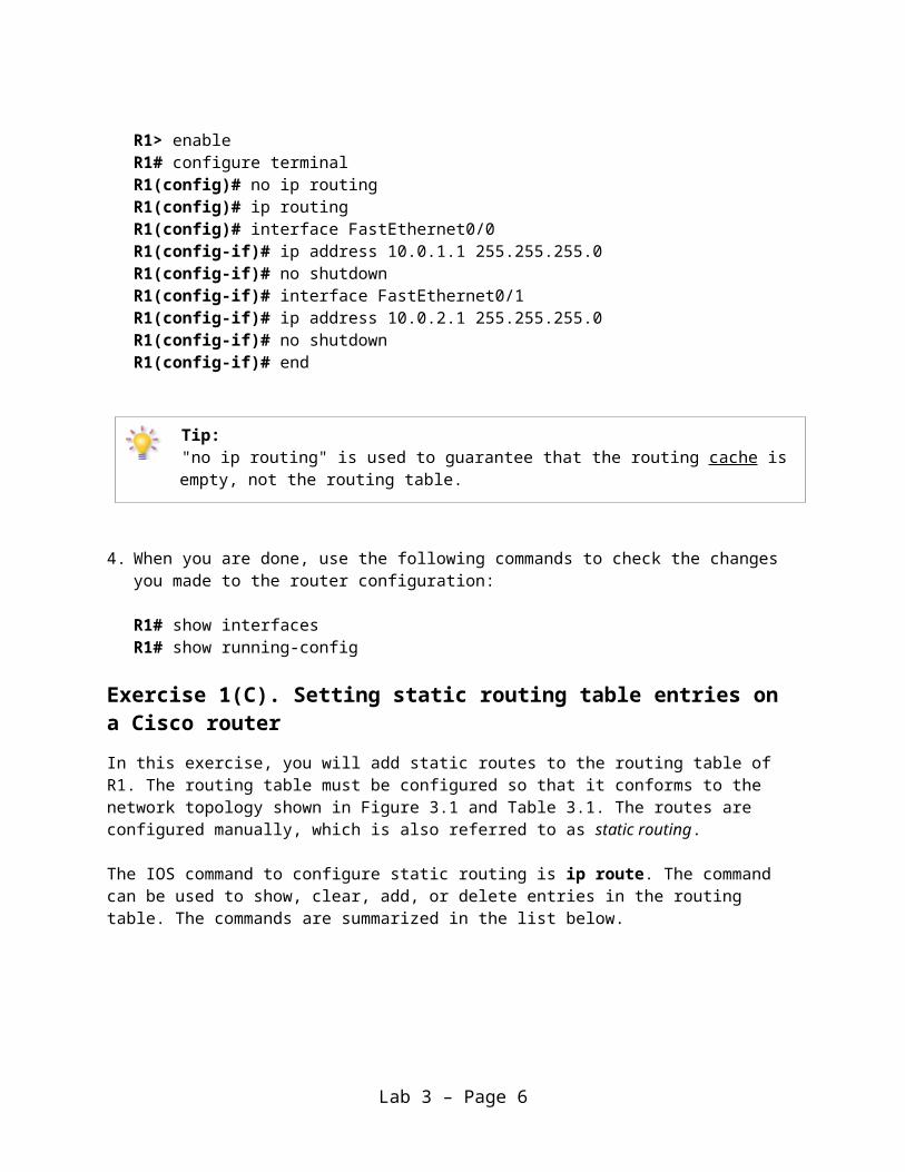
R1> enableR1# configure terminalR1(config)# no ip routingR1(config)# ip routingR1(config)# interface FastEthernet0/0R1(config-if)# ip address 10.0.1.1 255.255.255.0R1(config-if)# no shutdownR1(config-if)# interface FastEthernet0/1R1(config-if)# ip address 10.0.2.1 255.255.255.0R1(config-if)# no shutdownR1(config-if)# end
Tip: "no ip routing" is used to guarantee that the routing cache is empty, not the routing table.
4. When you are done, use the following commands to check the changes you made to the router configuration:
R1# show interfacesR1# show running-config
Exercise 1(C). Setting static routing table entries on a Cisco routerIn this exercise, you will add static routes to the routing table of R1. The routing table must be configured so that it conforms to the network topology shown in Figure 3.1 and Table 3.1. The routes are configured manually, which is also referred to as static routing.
The IOS command to configure static routing is ip route. The command can be used to show, clear, add, or delete entries in the routing table. The commands are summarized in the list below.
Lab 3 – Page 4

IOS MODE: PREVILEGED EXEC
show ip routeDisplays the contents of the routing table.
clear ip route *Deletes all routing table entries.
show ip cacheDisplays the routing cache.
IOS MODE: GLOBAL CONFIGURATION
ip route destination mask gw_addressno ip route destination mask gw_address
Adds or deletes a static routing table entry to destination with netmask mask. The argument gw_address is the IP address of the next-hop router.
ip route 0.0.0.0 0.0.0.0 gw_addressno ip route 0.0.0.0 0.0.0.0 gw_address
Adds or deletes a default routing table entry to a gateway where gw_address is the IP address of the next-hop router
ip route destination mask Ifaceno ip route destination mask Iface
Adds or deletes a static routing table entry to destination with netmask mask. Here, the next-hop information is the name of a network interface (e.g. FastEthernet0/0).
Next we show some examples for adding and deleting routing table entries in Cisco IOS. Note that whenever an IP address is configured for a network interface on a router, routing table entries for the directly connected network are added automatically.
The command for adding a route on R1 for the network address 10.0.1.0/24 with 10.0.2.22 as the next-hop gateway IP address is
R1(config)# ip route 10.0.1.0 255.255.255.0 10.0.2.22
NOTEThis is very important because if you do not set up the IP routes between the routers, the routers will never be able to ping each other from remote networks.
Lab 3 – Page 5
The command below shows you how to add a host route to a host with IP address 10.0.2.65 with next-hop (gateway) set to 10.0.1.21. In IOS, a host route is identified by a 32bit prefix.
R1(config)# ip route 10.0.2.65 255.255.255.255 10.0.1.21
The command to add e.g. the IP address 10.0.4.4 as the default gateway is done with the command
R1(config)# ip route 0.0.0.0 0.0.0.0 10.0.4.4
Finally, to delete any specific entry use the no ip route command. For example:
R1(config)# no ip route 10.0.1.0 255.255.255.0 10.0.2.22R1(config)# no ip route 10.0.2.65 255.255.255.255 10.0.1.21R1(config)# no ip route 0.0.0.0 0.0.0.0 10.0.4.4
1. Display the content of the routing table with show ip route. Note the routing entries that are already present. Save the output.
2. Add routing entries to R1 and R2, so that the routers forward datagrams and operate correctly for the configuration shown in Figure 3.1. Routing entries should exist for the following networks in each router (either directly connected or via a nexthop/gateway).a) 10.0.1.0/24 b) 10.0.2.0/24 c) 10.0.3.0/24
3. Display the routing table again with show ip route and save the output.
Lab Questions Explain the fields of the routing table entries of the Cisco router.
Lab 3 – Page 6

PART 2. Configuring a PC with static routesExercise 2(A). Network setup1. Start all the PCs on GNS3. Then, configure the IP addresses of the interfaces as given in
Table 3.1.
2. Start Wireshark to capture traffic on PC1.
3. Issue a ping command from PC1 to R1, R2 and PC4, respectively.
PC1% ping 10.0.1.1 –c 5PC1% ping 10.0.2.2 –c 5PC1% ping 10.0.3.41 –c 5
4. Save the captured Wireshark output.
Lab QuestionsUse the saved data to answer the following questions:
• What is the output on PC1 when the ping commands are issued?• Which packets, if any, are captured by Wireshark?• Do you observe any ARP or ICMP packets? If so, what do they indicate?• Are some of the destinations not reachable? If yes, which ones?
Exercise 2(B). Setting static routing table entries for a PCNext, you will set up the routing tables of the PCs. The routing tables are configured so that they conform to the network topology shown in Figure 3.1 and Table 3.1.
Configuring static routes in Linux is done with the command route, which has numerous options for viewing, adding, deleting, or modifying routing entries. The various uses of the route command are summarized in the list below.
In Linux, there is no simple way to delete all entries in the routing table. When the commands are issued interactively in a Linux shell, the added entries are valid until Linux is rebooted. To make static routes permanent, the routes need to be entered in the configuration file /etc/sysconfig/static-routes, which is read each time Linux is started.
route add –net netaddress netmask mask gw gw_addressroute add –net netaddress netmask mask dev iface
Adds a routing table entry for the network prefix identified by IP address netaddress
Lab 3 – Page 7

and netmask mask. The next-hop is identified by IP address gw_address or by interface iface.Example: The command for adding a route for the network address 10.21.0.0/16 with next-hop address 10.11.1.4 is:route add –net 10.21.0.0 netmask 255.255.0.0 gw 10.11.1.4
route add –host hostaddress gw gw_addressroute add –host hostaddress dev iface
Adds a host route entry for IP address hostaddress with the next-hop identified by IP address gw_address or by interface iface.
route add default gw gw_addressSets the default route to IP address gw_address.
route del –net netaddress netmask mask gw gw_addressroute del –host hostaddress gw gw_addressroute del default gw gw_address
Deletes an existing route from the routing table with specific arguments.
route -eDisplays the current routing table with extended fields. The command is identical to the netstat –r command.
ip route flush table maindeletes all entries in the routing table on a PC
ip route flush cachedeletes all entries in a routing cache on a PC
Please note that the default route should be added before adding any other static route entries, once you have flushed the routing table and cache.
ip route get IPAddressdisplays the cached route for IPAddress
ip route flush cache IPAddressflushes the cached route entry for IPAddress
Tip: The listed commands are helpful to get information on routing and to find mistakes in the routing setup. The ping command tests whether IPaddr can be reached or not, and the traceroute command displays the route to an
IPaddr. ping IPaddrtraceroute IPaddr
1. Configure the routing table entries of PC1 and PC4. You can either specify a default route or you can insert separate routing entries for each remote network. For this exercise, add a route for each individual remote network. Below we show you how to set up the routing configuration for PC4. Follow similar steps to setup the static routes on PC1.
Lab 3 – Page 8

PC4% route add –net 10.0.2.0 netmask 255.255.255.0 gw 10.0.3.1PC4% route add –net 10.0.1.0 netmask 255.255.255.0 gw 10.0.3.1
2. Display the routing table of PC1 and PC4 with netstat –rn and screenshot the output.
Lab Questions Explain the entries in the routing table and discuss the values of the fields for each entry.
Lab 3 – Page 9

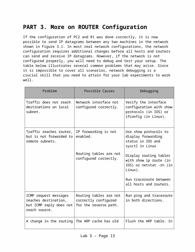
PART 3. More on ROUTER ConfigurationIf the configuration of PC2 and R1 was done correctly, it is now possible to send IP datagrams between any two machines in the network shown in Figure 3.1. In most real network configurations, the network configuration requires additional changes before all hosts and routers can send and receive IP datagrams. However, if the network is not configured properly, you will need to debug and test your setup. The table below illustrates several common problems that may arise. Since it is impossible to cover all scenarios, network debugging is a crucial skill that you need to attain for your lab experiments to work well.
Problem Possible Causes Debugging
Traffic does not reach destinations on local subnet.
Network interface not configured correctly.
Verify the interface configuration with show protocols (in IOS) or ifconfig (in Linux).
Traffic reaches router, but is not forwarded to remote subnets.
IP forwarding is not enabled.
Routing tables are not configured correctly.
Use show protocols to display forwarding status in IOS and sysctl in Linux
Display routing tables with show ip route (in IOS) or netstat -rn (in Linux).
Run traceroute between all hosts and routers.
ICMP request messages reaches destination, but ICMP reply does not reach source.
Routing tables are not correctly configured for the reverse path.
Run ping and traceroute in both directions.
A change in the routing table has no effect on the flow of traffic.
The ARP cache has old entries. Flush the ARP table. In Linux, delete entries with arp –d IPAddress. In IOS, use the command clear arp.
Lab 3 – Page 10

Exercise 3(A). Testing the network setup1. Test the network configuration by issuing ping commands from each host and router to
every other host and router. If some ping commands do not work, you need to modify the software configuration of routers and hosts. If all ping commands are successful, the network configuration is correct, and you can proceed to the next step.
2. Start a Wireshark session on PC1.
3. Execute a traceroute command from PC1 to PC4, and save the output.
PC1% traceroute 10.0.3.414. Execute a trace command from R1 to PC4, and save the output.
R1# trace 10.0.3.41
5. Stop Wireshark and save the captured traffic. Observe how traceroute commands gather route information.
6. Save the routing table of PC1, PC4, R1 and R2.
Lab Question Using the Wireshark output and the previously saved routing tables, explain the operation of
traceroute command.
Exercise 3(B). Observe MAC addresses at a routerWhen a router forwards an IP datagram from one Ethernet segment to another, it does not modify the IP destination address. However, it modifies the destination address in the Ethernet header.
This exercise requires manipulations to the ARP cache. The ARP command in Linux was covered in Lab 2. The list shows corresponding IOS commands for Cisco routers.
IOS MODE: PRIVILEGED EXEC
show arpDisplays the contents of the ARP cache
clear arp-cacheDeletes the entire ARP cache
IOS MODE: GLOBAL CONFIGURATION
arp IPaddressno arp IPaddressAdds or deletes an ARP entry for IPaddress in the ARP cache.
Lab 3 – Page 11

1. Erase all ARP entries on PC1, PC4, and R1, R2.
2. Run Wireshark on both PC1 and PC4.
3. Issue a ping command on PC1 to PC4.
PC1% ping 10.0.3.41 –c 5
4. Save the packet transmissions triggered by the ping command, including ARP Request, ARP reply, ICMP Echo Request, ICMP Echo Reply on both PC1 and PC4.
Lab Questions• Determine the source and destination addresses in the Ethernet and IP headers, for the
ICMP Echo Request messages that were captured at PC1.• Determine the source and destination addresses in the Ethernet and IP headers, for the
ICMP Echo Request messages that were captured at PC4.• Use your answers above to explain how the source and destination Ethernet and IP
addresses are changed when a datagram is forwarded by a router.
Exercise 3(C). Order of the routing table lookup
A router or host uses a routing table to determine the next hop of the path of an IP datagram. Generally, routing table entries are sorted in the order of decreasing prefix length, and are read from top to bottom. In this exercise, you determine how an IP router or PC resolves multiple matching entries in a routing table.
1. Add the following routes to the routing table of PC1:
PC1% route add –net 10.0.0.0 netmask 255.255.0.0 gw 10.0.1.71PC1% route add –host 10.0.3.9 gw 10.0.1.81
From Exercise 1(C), there should be a network route for the network prefix 10.0.3.0/24. If there is no such route, then add the following entry:
PC1% route add –net 10.0.3.0 netmask 255.255.255.0 gw 10.0.1.61
2. Referring to the routing table, determine how many matches exist for the following IP addresses:a) 10.0.3.9b) 10.0.3.14 c) 10.0.4.1
3. Start a Wireshark session on PC1, and issue the following ping commands from PC1:
PC1% ping 10.0.3.9 –c 5PC1% ping 10.0.3.14 –c 5PC1% ping 10.0.4.1 –c 5
Lab 3 – Page 12
Note that gateways with IP addresses 10.0.1.61, 10.0.1.71, and 10.0.1.81 do not exist.
4. Save the output of Wireshark and PC1's routing table.
Lab Question Use the saved output to indicate the number of matches for each of the IP addresses above.
Based upon what you have seen, explain how PC1 resolves multiple matches in the routing table. Depending on how you set up PC1’s routing table, you will get different responses (i.e., if you used default route or explicit entries for 10.0.2.0 and 10.0.3.0).
Exercise 3(D). Default routes
1. Delete the routing table entries added in Step 1 of Exercise 3(C) to PC1 above using the "route del" command. (Otherwise, the entries will interfere with the remaining exercises in this lab.)
2. Add default routes on PC1 an PC4.
a) On PC1, add a default route with interface FastEthernet0/0 on R1 as the default gateway.
b) On PC4, add a default route with interface FastEthernet1/0 of R2 as the default gateway.
3. Start Wireshark to capture traffic on PC1.
4. Issue a ping command from PC1 to a host on a network that does not exist, e.g.:
PC1% ping 10.0.10.110 –c 5
5. Save the Wireshark output.
Lab QuestionsUse the saved output to answer the following questions.
• What is the output on PC1, when the ping command is issued? • Determine how far the ICMP Echo Request message travels.• Which, if any, ICMP Echo Reply message returns to PC1?
Lab 3 – Page 13

PART 4. PROXY ARPProxy Address Resolution Protocol (Proxy ARP) enables a host to send packets to remote subnets without using its routing table. Proxy ARP is a configuration option when an IP router responds to ARP Requests that arrive from one of its connected subnets for a host that is on another of its connected subnets. Without Proxy ARP enabled, an ARP Request for a host on a different network would be unsuccessful, since routers do not forward ARP packets to another subnet.
In this part, you explore how Proxy ARP enables routers to forward an IP datagram even though the sender of the datagram is not aware that the IP datagram should be forwarded to a router. Continue with the network configuration from Figure 3.1, and with IP addresses as shown in Table 3.1. The commands to enable and disable Proxy ARP in IOS are listed below.
IOS MODE: INTERFACE CONFIGURATION
ip proxy-arpno ip proxy-arp
Proxy ARP is enabled and disabled separately on each interface. In IOS, proxy ARP is enabled by default.
Exercise 4. Observing Proxy ARP
1. Erase both the ARP table AND the routing table of PC4.
2. Set the netmask of PC4 to 255.0.0.0, so that PC4 assumes it belongs to subnet 10.0.0.0/8, not 10.0.3.0/24.
3. Run Wireshark on PC4 and PC1. Set a display or capture filter to ICMP and ARP packets only.
4. Issue a ping from PC4 to PC1:
PC4% ping 10.0.1.11 –c
a) Explore the captured data and interpret the outcome.
Even though PC4 had no default routing entry in its table for R2, it was still able to connect to PC1, i.e., you should not observe a network unreachable response.
5. Save the ARP table of PC4 and the packets captured by Wireshark on the hosts.
6. Explore the captured data and interpret the outcome.
7. Now, disable Proxy ARP on both interfaces of R2. Is it still feasible to issue a ping from PC4 to PC1?
Lab 3 – Page 14

8. Reset the subnet mask of PC4 to its original value of 255.255.255.0. Re-enable Proxy ARP on R2.
Lab Question• Use the captured data to explain the outcome of the exercise.• Use the data to explain how Proxy ARP allowed PC4 to communicate with PC1.
Lab 3 – Page 15
PART 5. ICMP ROUTE REDIRECTICMP route redirect messages are sent from a router to a host, when a datagram should have been forwarded to a different router or interface. In Linux, an ICMP route redirect message updates the routing cache, but not the routing table.
Both the routing cache and the routing table contain information for forwarding traffic. Before a Linux system performs a routing table lookup, it first inspects the routing cache. If no matching entry is round in the cache, Linux performs a lookup in the routing table. After each routing table lookup, an entry is added to the routing cache. The routing cache does not aggregate table entries, and there is a separate entry for each destination IP address. As a consequence, a lookup in the routing cache does not require a longest prefix match. An entry in the routing cache is deleted if it has not been used for some time, usually after 10 minutes. When an ICMP Redirect message arrives, an entry is added to the routing cache, but no update is performed to the routing table.
Recall the following commands to display the contents of the routing cache in Linux:
ip route get IPAddress
To clear the route cache in Linux:
ip route flush cache IPAddressor
ip route flush cache
Similarly for IOS the commands are:
show ip cacheclear ip cache
In this part of the lab, you will use three Cisco routers. Figure 3.2 and Table 3.2 describe the network configuration for the exercises below.
Lab 3 – Page 16

Figure 3.2 Network topology for Part 5
Cisco Routers FastEthernet0/0 FastEthernet1/0
R1 10.0.1.1 / 24 10.0.2.1 / 24
R2 10.0.3.2 / 24 10.0.2.2 / 24
R3 10.0.3.3 / 24 10.0.4.3 / 24
PC Ethernet Interface eth0
PC1 10.0.1.10 / 24
PC2 10.0.2.10 / 24
PC3 10.0.3.10 / 24
PC4 10.0.4.10 / 24
Table 3.2 IP address for Part 5
Exercise 5. Observing ICMP Redirect
In the network shown in Figure 3.2, when PC2 sends datagrams with destination 10.0.3.10 (PC3) to 10.0.2.1 (R1), as opposed to 10.0.2.2 (R2), then R1 sends an ICMP route redirect message to PC2. The ICMP route redirect informs PC2 that it should send datagrams with destination 10.0.3.10 to R2 instead.
In this exercise, you will create the above scenario. You will trigger the transmission of an ICMP Route Redirect message and subsequently observe a change to the routing cache.
1. Connect the Ethernet interfaces of the routers and the hosts to the hubs as shown in Figure 3.2.
2. Delete the routing table entries, route caches and ARP caches on all PCs and on all Routers.
Lab 3 – Page 17

3. Build a new static routing entry on R1 for network 10.0.3.0/24 to R2 (FastEthernet1/0)
4. ICMP redirect messages can be used to attack a network. For this reason, hosts by default ignore ICMP redirect messages. On a Linux system, the accept_redirects variable controls whether the host can accept or not a redirect ICMP message.
a) Use sysctl command to verify the current ICMP redirect status on PC2
PC2% sysctl net.ipv4.conf.all.accept_redirectsb) If the response is “0”, then you need to enable it. E.g., enable PC2 to accept ICMP
redirect messages.
PC2% echo 1 | tee /proc/sys/net/ipv4/conf/*/accept_redirects
c) Use the sysctl command again to ensure that the parameter change occurred.
5. Set up the routing table of PC2 in such a way that it provokes the transmission of an ICMP route redirect message as discussed above. In other words, force it to send the packet to a router other than the one you would expect to have it use to get to PC3.
6. Save the contents of the routing table and the routing cache on each of R1, R2, and PC2.
7. Set up the routing table of PC3 so that it can reach PC2.
8. Use Wireshark to capture the ICMP messages being sent and issue a ping from PC2 to PC3.
9. Save the network traffic and the contents of the routing table and the routing cache of PC2, and R1, R2 after the ICMP redirect messages.
10. Wait a few minutes with no action and check the contents of the routing cache again. Save the output.
Lab Questions• Is there a difference between the contents of the routing table and the routing cache
immediately after the ICMP route redirect message?• When you viewed the cache a few minutes later, what did you observe?• Describe how the ICMP route redirect works using the outputs you saved. Include only
relevant data from your saved output to support your explanations.• Explain how R1, in the above example, knows that datagrams destined to network
10.0.3.10 should be forwarded to 10.0.2.2?
Lab 3 – Page 18

PART 6. Routing LOOPS
A potential problem when setting routing tables manually is that routing loops may occur. In this part of the lab, you will intentionally configure a loop in the network configuration and observe what happens to network traffic in such a situation.
Figure 3.3 Network topology for Part 6
Cisco Routers FastEthernet0/0 FastEthernet1/0
R1 10.0.1.1 / 24 10.0.2.1 / 24
R2 10.0.3.2 / 24 10.0.2.2 / 24
R3 10.0.3.3 / 24 10.0.4.3 / 24
R4 10.0.4.4 / 24 10.0.2.4 / 24
PC Ethernet Interface eth0
PC1 10.0.1.10 / 24
PC2 10.0.2.10 / 24
PC3 10.0.3.10 / 24
PC4 10.0.4.10 / 24
Table 3.3 IP addresses for Part 6
Exercise 4. Observing forwarding loops
1. Set up the network topology as shown in Figure 3.3 and configure the interfaces as shown in Table 3.3.
2. Set up all the PC routing tables to allow communication between all 4 PCs.
Lab 3 – Page 19

3. Configure the routing tables of R2, R3 and R4, so that an ICMP Echo Request message generated by a ping from PC4 to PC1 creates an infinite loop. Issue a traceroute to verify that a loop exists:
PC4% traceroute 10.0.1.10
You should observe that the traced path is a loop.
4. Start Wireshark sessions on PC2, PC3, and PC4.
5. Issue a ping from PC4 to PC1. You should observe the same ICMP Echo Request message looping in Wireshark.
6. Save the routing tables of R2, R3 and R4. Count the number of times you see the ICMP Echo Request message, as captured by Wireshark on PC4. Save at least two of these ICMP Echo Request messages.
Lab Questions• Are the two packets that you saved identical? If not, what is different? • Why does the ICMP Echo Request packet not loop forever in the network?
Lab 3 – Page 20

PART 7. NETWORK PREFIXES and ROUTINGIn this exercise you study how the network prefixes (netmasks) play a role when hosts determine if a datagram can be directly delivered or if it must be sent to a router.
This part uses the network setup shown in Figure 3.4. The network includes one router, four hosts and two hubs. The IP addresses of all devices are given in Table 3.4. Here, each host has only a default route. In other words, the routing table at a host only knows about the directly connected networks and the default gateway.
Figure 3.4 Network topology for Part 7.
PCs Ethernet Interface eth0
PC1 10.0.1.10 / 24
PC2 10.0.2.10 / 24
PC3 10.0.2.137 / 29
PC4 10.0.2.139 / 24
Cisco Routers FastEthernet0/0 FastEthernet0/1
R1 10.0.1.1 / 24 10.0.2.138 / 24
Table 3.4. IP addresses for Part 7.
Lab 3 – Page 21

Exercise 5. Exploring the role of prefixes at hosts
In this exercise, you explore how hosts that are connected to the same local area network, but that have different netmasks, communicate or fail to communicate.
1. Configure the hosts and the router to conform to the topology shown in Figure 3.3, using the IP addresses as given in Table 3.3. Note that PC2, PC3, and PC4 have different netmasks.
2. Add R1 as default gateway on all hosts. (PC1, PC2, PC3, and PC4.)
3. Issue ping commands from PC1
a) Clear the ARP table on all PCs.
b) Start Wireshark on PC1 and PC3, and set the capture filter to capture ICMP and ARP packets only.
c) Issue a ping command from PC1 to PC3 for at least 5 sends (-c 5).
d) Save the output of the ping command at PC1 and the output of Wireshark on PC1 and PC3.
e) Save the ARP tables, routing tables, and routing caches of each host. Please note that these are the tables entries from Step 3 after the ping commands are issued.
4. Issue ping commands from PC3 to PC4
a) Clear the ARP table on all PCs.
b) Start Wireshark on PC3 and set the capture filter to capture ICMP and ARP packets only.
c) Check the ARP table, routing table, and routing cache of each host. Save the output. Please note that these are the table entries from Step 4 before the ping is issued.
d) Issue a ping command from PC3 to PC4 for at least 5 sends (-c 5)
e) Save the output of the ping command and the output of Wireshark on PC3.
f) Save the ARP table, routing table, and routing cache of PC3. Please note that these are the table entries from Step 4 after the ping commands are issued.
5. Repeat Step 4, but this time issue a ping from PC3 to PC2. Note that once an entry is made in the routing cache, you cannot repeat the previous experiment to obtain the same results. You have to wait until the routing cache is reset or you can delete all the routing caches on all devices.
Lab 3 – Page 22

Lab Questions• Explain what you observed in steps 3, 4 and 5. Use the saved data to support your answers.
Provide explanations of the observations. Try to explain each observed phenomenon, e.g., if you observe more ICMP Echo Requests than Echo Replies, try to explain the reason.
• If PC3 had no default entry in its table, would you have seen the same results? Explain for each of the pings above what would have been different
Lab 3 – Page 23

APPENDIX A. A TIP TO SPEED UP EXPERIMENTS
To configure the cisco routers and PCs, you are required to enter the commands manually in the console window. By now you will probably have realized that many of the commands are repeated. Also, you probably noticed that GNS3 resets PC and Cisco router configurations when you stop a GNS3 project. Saving the commands in a file and then using copy and paste of the command set will save you a lot of time.
Below we show you how you can save configuration commands in a Microsoft Excel Spread Sheet, for use at a later time.
1. Open an Excel spread sheet. Then, add a command in each row as shown in Figure A.1. The columns represent the different devices you are saving commands for.
Figure A.1
2. Select a command set from a column and copy the block of commands by pressing the shortcut key “Ctrl + C” for Windows and “Command + C” for Mac. The command set will be highlighted as shown in Figure A.2.
Lab 3 – Page 24

Figure A.2
3. Start a Cisco router R1 and a PC1 in GNS3.
4. Open console windows for each of R1 and PC1.
5. Now you paste the commands by right click on the console windows for Windows users. For Mac users, paste the commands with the shortcut key “Command + V”. You will see that the commands are executing as shown in Figure A.3 for R1.
Figure A.3
Lab 3 – Page 25

6. Repeat the above step to configure PC1.
7. Please make sure that the commands do not contain any typos.
8. Save the excel spread sheet. You can use for the next experiment if the configuration is similar. If not you can edit the saved file, e.g., IP address may have changed. And repeat the copy-paste routing to configure your devices.
Lab 3 – Page 26

APPENDIX B. HOW TO STORE LINUX CONFIGURATION
By default, all the configurations will be refreshed when you stop an ipterm node or close a project. This could be inconvenient, especially when GNS3 freezes and you are forced to restart from scratch.
In this appendix you will learn a tip on how to store Linux configurations.
1. Right click on a PC node, as shown in Figure B.1. For example, right click on PC1 from GNS3 project.
Figure B.1
2. Select “Edit config” from the menu.
3. The window shown below will open. Add or delete the configuration that is shown by (un)commenting lines, and editing the variables. For example, you can uncomment some lines by removing “#” as shown in figure B.2, or adding a "#" if you dont want a line in your configuration. You can change the IP address, or netmask, etc., by changing the values.
Figure B.2
Lab 3 – Page 27
4. You can also configure the PC to run any Linux commands automatically. Specify the Linux commands after the “post-up” keyword. For example, you can add an ARP table entry of 11:22:33:44:55:66 for an IP address 10.0.1.31 as follows:
post-up arp -s 10.0.1.31 11:22:33:44:55:66post-up ls -al
Figure B.3
Lab 3 – Page 28

APPENDIX C. HOW TO STORE CISCO RUNNING CONFIGURATION
By default, all the cisco IOS configurations will be refreshed when you stop a cisco router node. When you want to stop a GNS3 session and revisit the work later on, you have to retype all of the commands again from the beginning. To prevent this inconvenience, GNS3 provides a way to store a running configuration.
In this appendix, you will learn how to store a cisco running configuration.
1. Open GNS3 Preferences window from “Edit” menu. And select “IOS routers” in the left side menu and select c3640 as shown in Figure C.1.
Figure C.1
2. Click the button “Edit”, you will see the “Dynamips IOS Router configuration” window. Select the “Memories and disks” tab and uncheck “Automatically delete NVRAM and disk files”, as shown in Figure C.2.
Lab 3 – Page 29

Figure C.2
3. Now configure the routers in a GNS3 project. When you are done with the configuration, execute "copy running-config startup-config" in “exec” mode, then press the Enter key to overwrite the startup configuration. When the process is done, you will see a message “[OK]” as shown Figure C.3.
Lab 3 – Page 30

Figure C.3
4. Stop the current GNS3 project and save the project.
5. When you restart the project, and start the router, you will see that cisco restores the saved states. In our example, router R1 restored the IP address for FastEthernet0/0 as shown in Figure C.4.
Figure C.4
Lab 3 – Page 31