Embed Size (px)
Citation preview
Volume of interest CBCT and tube current modulation for image guidance usingdynamic kV collimationDavid Parsons and James L. Robar Citation: Medical Physics 43, 1808 (2016); doi: 10.1118/1.4943799 View online: http://dx.doi.org/10.1118/1.4943799 View Table of Contents: http://scitation.aip.org/content/aapm/journal/medphys/43/4?ver=pdfcov Published by the American Association of Physicists in Medicine Articles you may be interested in Technical Note: Phantom study to evaluate the dose and image quality effects of a computed tomographyorgan-based tube current modulation technique Med. Phys. 42, 6572 (2015); 10.1118/1.4933197 An investigation of kV CBCT image quality and dose reduction for volume-of-interest imaging using dynamiccollimation Med. Phys. 42, 5258 (2015); 10.1118/1.4928474 CBCT with specification of imaging dose and CNR by anatomical volume of interest Med. Phys. 41, 011909 (2014); 10.1118/1.4855835 Volume-of-interest cone-beam CT using a 2.35 MV beam generated with a carbon target Med. Phys. 39, 4209 (2012); 10.1118/1.4728977 Automatic exposure control in multichannel CT with tube current modulation to achieve a constant level ofimage noise: Experimental assessment on pediatric phantoms Med. Phys. 34, 3018 (2007); 10.1118/1.2746492
Volume of interest CBCT and tube current modulation for imageguidance using dynamic kV collimation
David Parsonsa)
Department of Physics and Atmospheric Science, Dalhousie University, 5820 University Avenue,Halifax, Nova Scotia B3H 1V7, Canada
James L. Robara)
Department of Radiation Oncology and Department of Physics and Atmospheric Science,Dalhousie University, 5820 University Avenue, Halifax, Nova Scotia B3H 1V7, Canada
(Received 1 December 2015; revised 26 February 2016; accepted for publication 28 February 2016;published 22 March 2016)
Purpose: The focus of this work is the development of a novel blade collimation system enablingvolume of interest (VOI) CBCT with tube current modulation using the kV image guidance sourceon a linear accelerator. Advantages of the system are assessed, particularly with regard to reductionand localization of dose and improvement of image quality.Methods: A four blade dynamic kV collimator was developed to track a VOI during a CBCTacquisition. The current prototype is capable of tracking an arbitrary volume defined by the treatmentplanner for subsequent CBCT guidance. During gantry rotation, the collimator tracks the VOIwith adjustment of position and dimension. CBCT image quality was investigated as a function ofcollimator dimension, while maintaining the same dose to the VOI, for a 22.2 cm diameter cylindricalwater phantom with a 9 mm diameter bone insert centered on isocenter. Dose distributions weremodeled using a dynamic BEAMnrc library and DOSXYZnrc. The resulting VOI dose distributionswere compared to full-field CBCT distributions to quantify dose reduction and localization to thetarget volume. A novel method of optimizing x-ray tube current during CBCT acquisition wasdeveloped and assessed with regard to contrast-to-noise ratio (CNR) and imaging dose.Results: Measurements show that the VOI CBCT method using the dynamic blade system yields anincrease in contrast-to-noise ratio by a factor of approximately 2.2. Depending upon the anatomicalsite, dose was reduced to 15%–80% of the full-field CBCT value along the central axis plane anddown to less than 1% out of plane. The use of tube current modulation allowed for specificationof a desired SNR within projection data. For approximately the same dose to the VOI, CNR wasfurther increased by a factor of 1.2 for modulated VOI CBCT, giving a combined improvement of 2.6compared to full-field CBCT.Conclusions: The present dynamic blade system provides significant improvements in CNR forthe same imaging dose and localization of imaging dose to a predefined volume of interest. Theapproach is compatible with tube current modulation, allowing optimization of the imaging protocol.C 2016 American Association of Physicists in Medicine. [http://dx.doi.org/10.1118/1.4943799]
Key words: volume of interest, cone-beam CT, dose reduction, current modulation
1. INTRODUCTION
Volume of interest (VOI) CBCT offers improved image qualityand dose reduction compared to full-field CBCT throughreduction of scatter generation within the patient.1–4 Chenet al.2 and Lai et al.3 have shown using a static copper colli-mator, scatter reductions of a factor of 6.6, compared to full-field CBCT, for example. This resulted in a contrast-to-noiseratio (CNR) improvement of a factor of approximately 1.45,with dose reductions by a factor of 1.2 and 2.7 inside andoutside the VOI, respectively, compared to full-field CBCT.Chen et al.2 and Lai et al.3 used an 11 cm breast phantom,with an 80 kVp beam and the same x-ray tube parameters forboth VOI and open-field CBCT. Similarly, Kolditz et al.5 havedeveloped a two arc VOI technique using a static collimatorand two isocenters, one arc for a low dose full-field acquisitionand the second for a high dose collimated VOI acquisition.
These data sets were combined using a combination of forwardprojection, registration, and weighting to reconstruct using theFeldkamp–Davis–Kress (FDK) algorithm.6 The result is a highquality VOI image with reduced noise and increased spatialresolution compared to outside the VOI, with 93.1% reduc-tion in dose compared to a conventional full-field scan withequivalent spatial resolution. Previously4 we demonstratedimplementation of kV VOI CBCT using a robotic, octagonaliris collimator that replaces the bowtie filter on an On-BoardImager (OBI) of a 2100 iX Varian linear accelerator (VarianMedical Systems, Inc., Palo Alto, CA). This was capableof increasing image CNR by up to a factor of 2 comparedto large fields for the same imaging dose, while decreasingthe lateral dose to the VOI to 30%–60% and less than 1%superior–inferior to the VOI, of the full-field value. However,the geometry of the x-ray aperture is restricted to an octagonwhich must encompass the longest dimension of the VOI in
1808 Med. Phys. 43 (4), April 2016 0094-2405/2016/43(4)/1808/10/$30.00 © 2016 Am. Assoc. Phys. Med. 1808

1809 D. Parsons and J. L. Robar: VOI CBCT and tube current modulation for IGRT 1809
each projection, thus limiting imaging dose conformity forelongated or irregular VOIs. In addition, the robotic collimatorwas implemented on a previous generation of Linac on-boardimaging (Clinac OBI, Varian Medical Systems, Inc., PaloAlto, CA) providing limited control over novel acquisitionprotocols.
Another possible degree of freedom in improving imagequality per unit dose is tube current modulation (TCM), whichhas widely been used in diagnostic computed tomographyfor the last several decades.7 This technique aims at adaptingtube current to the attenuation of the body region for a givenangle, thereby reducing imaging dose yet maintaining imagequality. However, the use in CBCT has been limited due to thelarge variation in attenuation along the longitudinal directioncompared to the variation throughout a single rotation aroundthe patient. TCM may be applicable to VOI CBCT, giventhat longitudinal extent of typical VOIs may be comparableto current generation multidetector CT.8 The combination ofVOI and tube current modulation could also be considered asimple form of fluence-field modulated CT.9–14 Gies et al.15
have previously described a method to calculate tube currentmodulation in CT based on the attenuation through the cen-tral axis, which results in a desired number of quanta at thedetector plane for every projection, showing that dose andimage noise could be reduced.16,17 For CBCT, Szczykutowiczand Mistretta10–12 described an approach in which fluence ismodulated by ten overlapping iron wedge pairs creating apiecewise-constant dynamic attenuator. By modulating flu-ence as a function of projection angle, they have shown thatthis technique is capable of decreasing dose and image noisewhile providing regions of high SNR compared to unmodu-lated CBCT. Similarly for CT, Hsieh et al.18 and Hsieh andPelc19 have described a piecewise-linear dynamic attenuatorusing two sets of abutting triangular wedges composed of iron,one offset laterally from the other by half of the triangle base.With this they also showed that fluence could be modulatedas a function of position and projection angle, resulting indecreases in dose and scatter-to-primary ratio. Bartolac et al.9
described a framework which calculates an optimal fluencedistribution using prescribed image quality and dose objectivesto various structures within the patient. This framework couldpotentially be implemented for a kV system using any ofthe above-mentioned attenuator techniques. Recently, Learyand Robar20 and Szczykutowicz et al.13 have successfullydemonstrated this concept using a multileaf collimator (MLC)in combination with a 2.5 MV carbon target on a Clinac(Varian Medical Systems, Inc., Palo Alto, CA) and a standard3.5 MV beam on a TomoTherapy unit (Accuray, Madison,WI), respectively.
In the current work, we demonstrate VOI CBCT withdynamic collimator and the enhancement of this imagingapproach by incorporating TCM. This is done by extending thefunctionality of the standard kV blades on a linear acceleratorimage guidance platform using a newly developed prototypedynamic collimator. We demonstrate the utility and advantagesof this technology with regard to image quality and dose reduc-tion in VOI CBCT. Finally, the compatibility and advantagesof TCM are examined.
2. MATERIALS AND METHODS2.A. Prototype dynamic collimator
A robotic blade system was developed to collimate theradiation field produced by the imaging system as a function ofgantry angle (Fig. 1). Similar to that in the commercial system(TrueBeam STx, Varian Medical Systems, Inc., Palo Alto,CA), the blades are composed of 2 mm of steel with an added3 mm of lead within the radiation field. The y-blades andx-blades are located on either sides of an aluminum base plate,which attaches to the frame of the x-ray tube. The y-blades(translating parallel to the axis of rotation) and x-blades (trans-lating perpendicular to the axis of rotation) are located approx-imately 20.2 and 22.9 cm from the anode, respectively. Bladetranslations are accomplished using stepper motors (E28H43-05-900, Haydon Kerk Motion Solutions, Inc., Waterbury, CT),one for each blade. This system is slightly more massive thanthe previously developed iris collimator,4 however remainswell below the weight tolerance of the source arm and showsnegligible impact on gravitational sag. The dynamic colli-mator interface was designed to be modular, i.e., allowingit to be easily ported to other CBCT imaging systems, andtherefore largely independent of the Linac on-board imaging.The collimator dynamics are controlled using a microcom-puter (Raspberry Pi 2 model B V1.1, Raspberry Pi Foundation,
F. 1. (Top) Robotic blade collimator attached to the x-ray tube on a VarianTrueBeam STx unit (Varian Medical Systems, Inc., Palo Alto, CA).
Medical Physics, Vol. 43, No. 4, April 2016
1810 D. Parsons and J. L. Robar: VOI CBCT and tube current modulation for IGRT 1810
Caldecote, UK) located within the gantry. Each stepper mo-tor is controlled using an A4983 microstepping driver chip(Allegro MicroSystems, Inc., Worcester, MA), coordinatingsimultaneous motion of each blade. The maximum field sizeis 27.2× 27.2 cm2, with complete overtravel of each blade.To determine gantry angle, a triple-axis digital accelerometer(ADXL345, Analog Devices, Inc., Norwood, MA) was used.
2.B. Volume of interest CBCT imaging
The previously described imaging paradigm by Parsons andRobar4 was used within this work. Briefly, a VOI is definedusing the Eclipse treatment planning system (TPS, VarianMedical Systems, Inc., Palo Alto, CA). To calculate bladelocations, the DICOM structure set of the VOI is exported
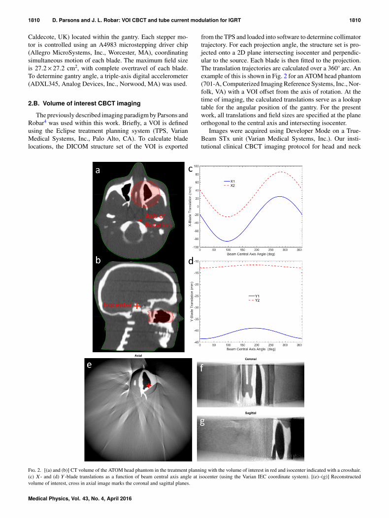
from the TPS and loaded into software to determine collimatortrajectory. For each projection angle, the structure set is pro-jected onto a 2D plane intersecting isocenter and perpendic-ular to the source. Each blade is then fitted to the projection.The translation trajectories are calculated over a 360◦ arc. Anexample of this is shown in Fig. 2 for an ATOM head phantom(701-A, Computerized Imaging Reference Systems, Inc., Nor-folk, VA) with a VOI offset from the axis of rotation. At thetime of imaging, the calculated translations serve as a lookuptable for the angular position of the gantry. For the presentwork, all translations and field sizes are specified at the planeorthogonal to the central axis and intersecting isocenter.
Images were acquired using Developer Mode on a True-Beam STx unit (Varian Medical Systems, Inc.). Our insti-tutional clinical CBCT imaging protocol for head and neck
F. 2. [(a) and (b)] CT volume of the ATOM head phantom in the treatment planning with the volume of interest in red and isocenter indicated with a crosshair.(c) X - and (d) Y -blade translations as a function of beam central axis angle at isocenter (using the Varian IEC coordinate system). [(e)–(g)] Reconstructedvolume of interest, cross in axial image marks the coronal and sagittal planes.
Medical Physics, Vol. 43, No. 4, April 2016

1811 D. Parsons and J. L. Robar: VOI CBCT and tube current modulation for IGRT 1811
patients was adapted for this work, using the following basex-ray tube parameters of a potential of 120 kVp, current of20 mA, pulse width of 20 ms, source-to-axis distance (SAD)of 100 cm, source-to-detector distance (SDD) of 150 cm, anda 200◦ arc.
The CBCT projections were reconstructed using the FDKalgorithm6 within iTools (Varian Medical Systems, iLabGmbH, Baden, Switzerland). The preprocessing steps weresimplified from previous VOI CBCT methods4 to accountfor the truncation artifacts associated when reconstructingVOI projections. Prior to reconstruction, the VOI projectionis masked using the a priori blade locations, eroded, theboundary of the VOI extrapolated and normalized.
For comparison to previous work with the robotic iris colli-mator,4 image CNR was investigated for the same dose toisocenter, using a 9 mm diameter by 3 cm long cylindrical boneinsert (density of 1.82 g/cm3) centered on isocenter containedwithin a 22.2 cm diameter by 20 cm long cylindrical waterphantom. CNR was calculated as
CNR=|PBone−PWater|
σWater, (1)
where PBone is the average pixel value within the bone insert,PWater is the average value of the water surrounding the bone,and σWater is the average noise in the water. Error bars werefound by calculating the mean and standard deviation of CNRmeasured among ten 1 mm slices above and below the centralslice.
2.C. 4D Monte Carlo for VOI CBCT
To calculate (modulated and unmodulated) VOI CBCTdose distributions Monte Carlo simulation were used. Thex-ray tube with prototype dynamic blade collimator wasmodeled in BEAMnrc21 using exact geometric and mate-rial specifications provided by Varian Medical Systems. Aphase–space was first generated immediately above the dy-namic blade collimation. This phase–space was then usedas an input for the VOI CBCT dose calculations. This wasdone for efficiency purposes as the bremsstrahlung distribu-tion throughout the rotation is constant, with only the bladecollimation changing. A 120 keV monoenergetic electronbeam was incident on the x-ray target. The incident elect-ron beam angle relative to the x-ray tube was simulatedaccording to manufacturer’s specifications. The directionalbremsstrahlung splitting variance reduction technique wasused, with a splitting radius of 17 cm for standard open fieldof 27.2× 20.6 cm2 and bremsstrahlung splitting number of2000. Similar to previous work where similar kV sourceswere modeled,4,22 the EGSnrc parameters listed in Table Iwere used; where not mentioned the default values were used.Global electron (ECUT) and photon (PCUT) cutoff energiesof 0.521 and 0.010 MeV, respectively, were used.
Source 20 in DOSXYZnrc and the SYNCJAWS compo-nent module developed by Lobo and Popescu23 were usedto simulate the synchronized blade translations with gantryrotation in DOSXYZnrc. The simulation was divided into200 control points. The CT DICOM information was ex-
T I. Particle transport parameters used in the Monte Carlo simulations.
EGSnrc parameter BEAMnrc/DOSXYZnrc
Electron impact ionization OnBremsstrahlung angular sampling Koch–MotzBremsstrahlung cross section NISTBound compton scattering OnPhotoelectron angular sampling OnRayleigh scattering OnAtomic relaxations OnPhoton cross sections NIST XCOM
ported from the TPS and used to create an EGSPHANTfile containing the material and density composition of thephantom.
2.D. Tube current modulation
The CT DICOM information was exported from the TPSand used to create linear attenuation coefficients matrix usingair, lung, tissue, and bone [as defined in ICRU-44 (Ref. 24)] fora 60 keV photon from the NIST database.25 60 keV was chosenas it is approximately the mean energy of the 120 kVp spec-trum from the x-ray tube on TrueBeam shown in Fig. 3. Sid-don’s method26 was then used to calculate an attenuation map(DRR) in , mimicking the physical setup of an SADand SDD of 100 and 150 cm, respectively. This was repeatedin 1◦ increments for a full rotation around the phantom. Theattenuation maps were then masked with the correspondingblade positions. The formulation developed by Gies et al.15
and modified by Szczykutowicz and Mistretta10,11 was usedto determine variation of fluence as a function of projectionangle. Briefly, this calculation is described using the followingequation from Gies et al.:15
Ni =No
Pi=1
√Ai
Ai, (2)
where Ni is the desired number of quanta after traversing thephantom for an angle i, No is the total number of emittedthroughout an acquisition, P is the number of projections,and Ai = eα(µL)i is the amount of attenuation through the
F. 3. 120 kVp open-field spectrum from the kV source on TrueBeam.
Medical Physics, Vol. 43, No. 4, April 2016

1812 D. Parsons and J. L. Robar: VOI CBCT and tube current modulation for IGRT 1812
F. 4. Attenuation maps for q equal to 100%, 70%, and 40%. Dashed box shows the location of the blades and data used in calculating(µL)i.
phantom for an angle i. Following the work of Szczykutowiczand Mistretta,10,11 an α parameter of 1 was chosen to equalizethe detector signal. Similarly, a q value was used to calculate(µL)i
for an angle i. This parameter is used to determine athreshold below which the mean is taken and can be usedto account for soft tissue/bone interfaces. More specifically,for each VOI projection, the attenuation values were sorted inascending order and the values up to the q percentile were usedto calculate the mean attenuation. Figure 4 shows three valuesof q for a projection of the VOI shown in Fig. 2 at a sourceangle of 180◦. For visualization purposes, information outsidethe VOI is shown but is not used in the determination of Ni.As shown, by reducing q, a greater portion soft tissue relativeto bone is used in determining
(µL)i.
Within Developer Mode on TrueBeam version 2.0, cur-rently only the pulse width can be altered between projectionacquisitions, as stated in Sec. 2.B, a tube current of 20 mA wasalways used with a minimum allowed exposure per image of0.4 mAs; therefore, a 20 ms pulse width was taken to be thelower bound for modulation. The above was then used to createan for Developer Mode.
To show that desired number of quanta was arriving atthe detector signal, projection SNR was measured throughten acquisitions of the VOI and phantom shown in Fig. 2.At each angle, the mean and standard deviation of each pixelvalue were recorded. SNR was then calculated as the averagemean over the average standard deviation, among acquisi-tions, for each angle. Image CNR was investigated using thephantom described in Sec. 2.B except the cylindrical boneinsert was placed 5.5 cm off-axis. The VOI was located off-axis to provide variation in attenuation. A 6.5 cm diameterby 2.5 cm long VOI was used with the bone insert at thecenter. Dose was measured by replacing the bone insert with a0.015 cm3 crosscalibrated ionization chamber (PTW N31010,Freiburg, Germany). Primary calibration was done using anExradin A12 ionization chamber (Standard Imaging, Inc.,Middleton, WI) with collecting volume of 0.65 cm3 usingthe TG-61 protocol.27 This process was done for q valuesof 25%, 50%, and 100% as well as unmodulated acquisitionusing a pulse width of 82 ms. 82 ms represents the pulse widthwhich gives approximately the same total mAs as a q valueof 100%.
3. RESULTS AND DISCUSSION3.A. Dynamic blade VOI CBCT
Figure 5 shows CNR measurements for the 22.2 cm diam-eter by 20 cm long water phantom with a 9 mm diameter by3 cm long bone insert centered on isocenter, for field sizesranging from 2×2 to 18×18 cm2. Compared to the previousiris collimator4 (field areas ranging from 3.9 to 316.3 cm2),VOI CBCT with the dynamic blade system provides a similarcontrast increase by a factor of 1.3 and noise reduction by afactor of 1.7 compared to full-field CBCT, and thus an increasein contrast-to-noise ratio by a factor of approximately 2.2.The results in Fig. 5 also demonstrate that the rate of CNRimprovement is most pronounced as field size is reduced belowapproximately 10×10 cm2.
Figure 6 shows VOI CBCT imaging dose distributions foran open-field and the VOI acquisition of the phantom shownin Fig. 2. Similar to previous work,4 this demonstrates that thehigh dose is mainly isolated to the VOI; however on the axial
F. 5. Contrast-to-noise ratio measurements for a 22.2 cm diameter by20 cm long water phantom with a 9 mm diameter by 3 cm long bone insertcentered on isocenter, for field sizes ranging from 2×2 to 18×18 cm2 field.
Medical Physics, Vol. 43, No. 4, April 2016

1813 D. Parsons and J. L. Robar: VOI CBCT and tube current modulation for IGRT 1813
F. 6. Dose distributions for the open field (top row) and volume of interest (middle row) acquisitions for image volumes shown in Fig. 2, in Gy per incidentelectron striking the x-ray target. (bottom row) Dose ratios of the volume of interest to open-field acquisitions. White contour shows the location of the VOI.
planes containing the VOI, a dose ranging from 20% to 50%of the full-field value exists, while the dose outside the planeis decreased to less than 1%. Extrapolating the above resultsto other anatomy would be challenging as the associated gainsin image quality and dose reduction are highly dependent onthe anatomy of interest, as well as the size and location of theVOI.
F. 7. Attenuation and pulse width as a function of beam central axis anglefor the VOI shown in Figs. 2(a) and 2(b) using a q value of 100% for acomplete rotation and the 200◦ arc with the lowest integral attenuation.
3.B. Modulated VOI CBCT
Figure 7 shows attenuation as a function of projection anglefor the VOI shown in Figs. 2(a) and 2(b) using a q value of100% as well as the arc path that represents the minimumintegral attenuation. Variation is approximately sinusoidal butwill depend on the shape of the patient, radiologic attenuation,
F. 8. Projection signal-to-noise ratio as a function of projection angle for amodulated (q = 100%) and unmodulated VOI acquisition for the VOI shownin Fig. 2.
Medical Physics, Vol. 43, No. 4, April 2016
1814 D. Parsons and J. L. Robar: VOI CBCT and tube current modulation for IGRT 1814
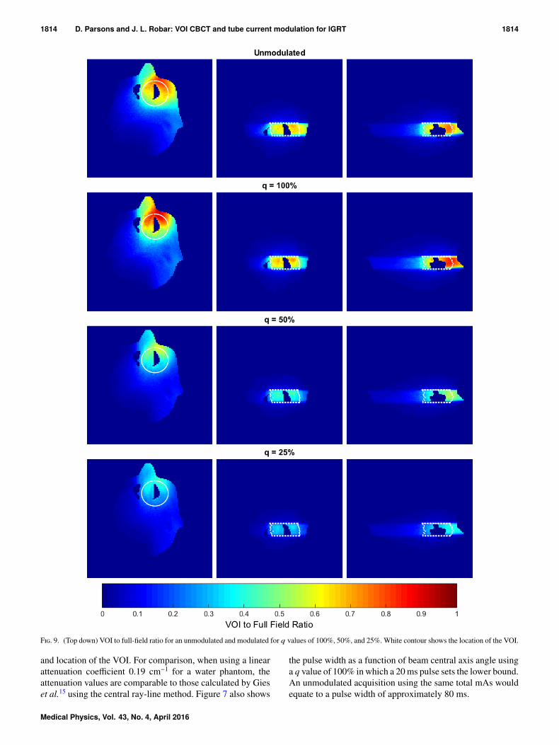
F. 9. (Top down) VOI to full-field ratio for an unmodulated and modulated for q values of 100%, 50%, and 25%. White contour shows the location of the VOI.
and location of the VOI. For comparison, when using a linearattenuation coefficient 0.19 cm−1 for a water phantom, theattenuation values are comparable to those calculated by Gieset al.15 using the central ray-line method. Figure 7 also shows
the pulse width as a function of beam central axis angle usinga q value of 100% in which a 20 ms pulse sets the lower bound.An unmodulated acquisition using the same total mAs wouldequate to a pulse width of approximately 80 ms.
Medical Physics, Vol. 43, No. 4, April 2016

1815 D. Parsons and J. L. Robar: VOI CBCT and tube current modulation for IGRT 1815
F. 10. (a) CNR, (b) VOI point dose measurement, and (c) total mAs for a diameter for a 22.2 cm diameter by 20 cm long water phantom with a 9 mm diameterby 3 cm long bone insert located 5.5 cm off-axis. A 6.5 cm diameter by 2.5 cm long VOI was used with the bone insert at the center. Monte Carlo simulated dosedifference from the unmodulated acquisition for (d) q = 100%, (e) q = 50%, and (f) q = 25% with the bone insert removed. The white arc indicates the 200◦ arcpath and start angle in Varian IEC coordinates. VOI location marked with a black circle.
Figure 8 shows projection SNR within the VOI as functionof beam central axis angle for a modulated and unmodulatedVOI CBCT acquisition of the VOI shown in Fig. 2. This showsthat modulated VOI CBCT results in approximately equivalentSNR throughout the rotation compared to the sinusoidal SNRof an unmodulated acquisition. Furthermore, the SNR of theunmodulated acquisition follows an inverted relationship ofthe attenuation. The above suggests that projection SNR couldbe prescribed using this method.
Figure 9 shows dose ratios for unmodulated and modu-lated VOI acquisitions compared to an unmodulated open-fielddose distribution. The use of modulation results in a slightincrease to the maximum dose to the VOI, with an increaseof approximately 10% compared to unmodulated acquisitionusing the same integral mAs. However, the dose to the VOIcan be reduced by lowering the q value, as shown for q valuesof 50% and 25%, giving dose reductions of 38% and 50%compared to a q value of 100%, respectively. Little variationin the dose outside the VOI is observed, with a reduction ofapproximately 10% 2 cm posterior to the VOI, when changingq value from 100% to 25%. Figure 9 also highlights howthe attenuation could be used to guide the arc path for anunmodulated acquisition.
Figure 10 shows CBCT image CNR, VOI dose, and totalmAs for unmodulated and modulated acquisitions using a6.5 cm diameter by 2.5 cm long VOI centered on a 9 mmdiameter by 3 cm long bone insert located 5.5 cm off-axisin the phantom described in Sec. 2.B. This shows that forapproximately the same total mAs and dose, a modulated(q = 100%) acquisition results in an increase in CNR by afactor of 1.2 compared to an unmodulated acquisition. Alsodemonstrated is that for approximately the same CNR, modu-lation with q = 25% gives a dose reduction by a factor of 1.6,compared to the unmodulated case. Interpolating from theseresults, q = 96% would deliver approximately the same doseto the VOI. This would correspond to a CNR of approximately23.9, giving an improvement by a factor of 1.16 compared to anunmodulated acquisition. It should be noted that, compared tofull-field CBCT imaging, these improvements are incrementalto those realized by use of the VOI approach alone, i.e., thoseshown in Figs. 5 and 6. Modulated VOI CBCT could resultin a CNR improvement as high as a factor of 2.6 comparedto open field. Additionally, Figs. 10(d)–10(f) show the dosedifference from the unmodulated and modulated acquisitions.The region anterior to the VOI shows a maximum dose reduc-tion of approximately 10 and 30 mGy for q values of 100% and
Medical Physics, Vol. 43, No. 4, April 2016
1816 D. Parsons and J. L. Robar: VOI CBCT and tube current modulation for IGRT 1816
25%, respectively, compared to no modulation. For a q valueof 100%, the surface dose adjacent to the VOI is increased byapproximately 8 mGy. For q values of 25% and 50%, the startangle was shifted compared to the unmodulated acquisition,and there is an increase of dose near the end of the arc byapproximately 5 mGy.
The main limitation of the technique presented within thiswork is that the planning CT set is required to calculate theattenuation maps used in determining Ai. While these dataare always available for image guidance, it would be difficultto implement in its current form in diagnostic imaging. Anapproach similar to Szczykutowicz and Mistretta10,11 could beused in which previous angle projections are used to determinethe desired signal in the current projection. This would requirethe first few angles of the arc to be unmodulated. Additionally,when the planning CT is available, calculating attenuationmaps at 1◦ increments can be a lengthy process; however,Jia et al.28 have shown that this process can efficiently becalculated using GPUs. Using a tool such as this would alsoallow the use of polyenergetic spectra, which would improvethe calculation for a variety of anatomical sites. This wouldalso allow for the management of beam hardening.
A premise of the VOI CBCT as implemented here is that allimage data outside the VOI are discarded during reconstruc-tion. However, the current modulation approach describedhere could provide an additional degree of freedom, e.g., inthe nested VOI sequences demonstrated by Leary and Ro-bar20 and Szczykutowicz et al.,13 allowing imaging of largeranatomical volumes while controlling levels of image qualityand dose throughout the imaged anatomy. Although morecomplex apertures would be involved, this approach may alsoassist in an evolution toward true fluence-field modulation asdescribed by Bartolac et al.9 in which detailed volumes couldbe prescribed individual image quality and dose objectives.
4. CONCLUSIONS
In this work, we have combined two advantageous ap-proaches in image acquisition for guidance of radiotherapy:(i) VOI CBCT, which localizes imaging dose to, for example,the planning target volume and (ii) modulation of mAs as afunction of projection angle. For the same imaging dose, theVOI CBCT method offers CNR improvements by up to a factorof 2.2 within the VOI. Peripheral dose outside of the VOI isreduced to 20%–50% of the dose value with a full-field CBCTapproach. When mAs modulation is applied, an additionalenhancement of CNR (e.g., factor of 1.2) is observed, withouta further increase in dose. These improvements are realizedwithout substantial changes in system design: while althoughwe used a novel prototype dynamic blade collimator, it is closein design to that used commercially, and the variation of pulsewidth during acquisition is already permitted by the Linacimage guidance platform, albeit in Developer Mode.
ACKNOWLEDGMENTS
The authors would like to thank Ian Porter for fabricationof the dynamic blade collimator, Robert Moran and David
Pepper for their vital electronic and technical support, andDr. I. A. Popescu for his knowledge in setting up the 4DMonte Carlo system with EGSnrc. The authors are grateful forsupport provided by Springboard Atlantic, Killam Trusts, theCanadian Institutes of Health Research, the Canadian NuclearSafety Commission. This work is supported through a researchagreement with Varian Medical Systems, Incorporated.
a)Electronic addresses: [email protected]; Telephone: 1 (902) 473-6062;Fax: 1 (902) 473-6120 and [email protected]; Telephone: 1 (902)473-6017; Fax: 1 (902) 473-6120.
1J. H. Siewerdsen and D. A. Jaffray, “Cone-beam computed tomography witha flat-panel imager: Magnitude and effects of x-ray scatter,” Med. Phys.28(2), 220–231 (2001).
2L. Chen, C. C. Shaw, M. C. Altunbas, C. J. Lai, X. Liu, T. Han, T. Wang,W. T. Yang, and G. J. Whitman, “Feasibility of volume-of-interest (VOI)scanning technique in cone beam breast CT—A preliminary study,” Med.Phys. 35(8), 3482–3490 (2008).
3C.-J. Lai, L. Chen, H. Zhang, X. Liu, Y. Zhong, Y. Shen, T. Han, S. Ge, Y. Yi,T. Wang, W. T. Yang, G. J. Whitman, and C. C. Shaw, “Reduction in x-rayscatter and radiation dose for volume-of-interest (VOI) cone-beam breastCT—A phantom study,” Phys. Med. Biol. 54(21), 6691–6709 (2009).
4D. Parsons and J. L. Robar, “An investigation of kV CBCT image quality anddose reduction for volume-of-interest imaging using dynamic collimation,”Med. Phys. 42(9), 5258–5269 (2015).
5D. Kolditz, Y. Kyriakou, and W. A. Kalender, “Volume-of-interest (VOI)imaging in C-arm flat-detector CT for high image quality at reduced dose,”Med. Phys. 37(6), 2719–2730 (2010).
6L. Feldkamp, L. Davis, and J. Kress, “Practical cone-beam algorithm,” J.Opt. Soc. Am. A 1(6), 612–619 (1984).
7GE Medical Systems CT Hispeed Advantage RP System, 15th ed. (GETechnical Publications, Milwaukee, WI, 1994).
8E. M. Hsiao, F. J. Rybicki, and M. Steigner, “CT coronary angiography:256-slice and 320-detector row scanners,” Curr. Cardiol. Rep. 12(1), 68–75(2010).
9S. Bartolac, S. Graham, J. Siewerdsen, and D. Jaffray, “Fluence field opti-mization for noise and dose objectives in CT,” Med. Phys. 38(7), S2–S17(2011).
10T. P. Szczykutowicz and C. A. Mistretta, “Design of a digital beam attenua-tion system for computed tomography: Part I. System design and simulationframework,” Med. Phys. 40(2), 021905 (12pp.) (2013).
11T. P. Szczykutowicz and C. A. Mistretta, “Design of a digital beam attenua-tion system for computed tomography. Part II. Performance study and initialresults,” Med. Phys. 40(2), 021906 (9pp.) (2013).
12T. P. Szczykutowicz and C. A. Mistretta, “Experimental realization of flu-ence field modulated CT using digital beam attenuation,” Phys. Med. Biol.59(5), 1305–1326 (2014).
13T. Szczykutowicz, J. Hermus, M. Geurts, and J. Smilowitz, “Realizationof fluence field modulated CT on a clinical tomotherapy megavoltage CTsystem,” Phys. Med. Biol. 60(18), 7245–7257 (2015).
14D. Heuscher and F. Noo, “CT dose reduction using dynamic collima-tion,” in The Second International Conference on Image Formation in x-ray Computed Tomography (Salt Lake City, UT, 2012), pp. 115–118, seehttp://www.ucair.med.utah.edu/CTmeeting/.
15M. Gies, W. A. Kalender, H. Wolf, C. Suess, and M. T. Madsen, “Dose reduc-tion in CT by anatomically adapted tube current modulation. I. Simulationstudies,” Med. Phys. 26(11), 2235–2247 (1999).
16W. A. Kalender, H. Wolf, and C. Suess, “Dose reduction in CT by anatom-ically adapted tube current modulation. II. Phantom measurements,” Med.Phys. 26(11), 2248–2253 (1999).
17W. A. Kalender, H. Wolf, C. Suess, M. Gies, H. Greess, and W. A. Bautz,“Dose reduction in CT by on-line tube current control: Principles andvalidation on phantoms and cadavers,” Eur. Radiol. 9, 323–328 (1999).
18S. S. Hsieh, D. Fleischmann, and N. J. Pelc, “Dose reduction using a dy-namic, piecewise-linear attenuator,” Med. Phys. 41, 021910 (14pp.) (2014).
19S. S. Hsieh and N. J. Pelc, “The feasibility of a piecewise-linear dynamicbowtie filter,” Med. Phys. 40(3), 031910 (12pp.) (2013).
20D. Leary and J. L. Robar, “CBCT with specification of imaging dose andCNR by anatomical volume of interest,” Med. Phys. 41(1), 011909 (7pp.)(2014).
Medical Physics, Vol. 43, No. 4, April 2016

1817 D. Parsons and J. L. Robar: VOI CBCT and tube current modulation for IGRT 1817
21D. W. Rogers, B. A. Faddegon, G. X. Ding, C. M. Ma, J. We, and T. R.Mackie, “Beam: A Monte Carlo code to simulate radiotherapy treatmentunits,” Med. Phys. 22(5), 503–524 (1995).
22G. X. Ding, D. M. Duggan, and C. W. Coffey, “Characteristics of kilovoltagex-ray beams used for cone-beam computed tomography in radiation ther-apy,” Phys. Med. Biol. 52(6), 1595–1615 (2007).
23J. Lobo and I. A. Popescu, “Two new DOSXYZnrc sources for 4D MonteCarlo simulations of continuously variable beam configurations, with appli-cations to RapidArc, VMAT, tomotherapy and CyberKnife,” Phys. Med.Biol. 55(16), 4431–4443 (2010).
24International Commission of Radiation Units and Measurements, TissueSubstitutes in Radiation Dosimetry and Measurement, ICRU Report 44,International Commission on Radiation Units and Measurements, Bethesda,MD, 1989.
25J. H. Hubbell and S. M. Seltzer, “Tables of x-ray mass attenuation coeffi-cients and mass energy-absorption coefficients 1 keV–20 MeV for elementsZ = 1–92 and 48 additional substances of dosimetric interest,” Report No.NISTIR 5632, National Institute of Standards and Technology, Gaithers-burg, MD, 1995.
26R. L. Siddon, “Fast calculation of the exact radiological path for a three-dimensional CT array,” Med. Phys. 12(2), 252–255 (2012).
27C. M. Ma, C. W. Coffey, L. A. DeWerd, C. Liu, R. Nath, S. M.Seltzer, and J. P. Seuntjens, “AAPM protocol for 40–300 kV x-ray beamdosimetry in radiotherapy and radiobiology,” Med. Phys. 28(6), 868–893(2001).
28X. Jia, H. Yan, L. Cerviño, M. Folkerts, and S. B. Jiang, “A GPU tool forefficient, accurate, and realistic simulation of cone beam CT projections,”Med. Phys. 39(12), 7368–7378 (2012).
Medical Physics, Vol. 43, No. 4, April 2016