Embed Size (px)
DESCRIPTION
Â
Citation preview

ABPL30048 ARCHITECTURE DESIGN STUDIO AIR STUDIO O1 CANHUI CHEN TAYLAH PARKERl
S T U D I O A I RD E S I G N J O U R N A L : P A R T B

I m a g e i A L g o r i t h m i c m o d e l i n g

iiiC O N T E N T S I m a g e i A L g o r i t h m i c m o d e l i n g
C O N T E N T S
P a r t a : c o n c e p t u a l i s a t i o n 2 - 2 1
V - V I i n t r o d u c t i o n
P a r t B : C R I T E R I A D E S I G N 2 2 - 5 9
i n t r o d u c t i o n iv
I m a g e 1 - 6 P a s t d e s i g n w o r k

I’m Taylah Parker, a third year architect student at Melbourne. Outside of university my interests predominantly include dance. Despite growing up with an understanding and appreciation for the fluidity of movement, I find that my interests in architecture are related more closely to the geometric form.
For most of my life I have found myself intrigued by the world that surrounds me. Particularly, when I used to walk to the football with my dad, I would look up at the surrounding structures in awe. I believe this sparked my interest in architecture.
I would say my existing knowledge of digital archi-tecture is relatively limited, especially in terms of being able to design and create it. There are projects that I have previously researched but other than being amazed at the entirety of the structure, I have always found, myself to become overwhelmed at the prospect of even construct-
ing the building. As an example, I’ve studied the timber post gridshell structures often seen in small pavilions. I am intrigued by how simplistic some designs can be. With only a few lines and repeated geometric shape an entire construct can accumulate
For me architecture is about establishing an experience that incorporates the users and space they inhabited. Furthermore, I was look to the future, I believe that is is important to be consid-erate of sustainable practices.
My technical understanding of digital design fabri-cation is limited to my use of Rhino3D. However, I tend to find with the models I create that they seem unrealistic. As I begin to learn Grasshopper, I hope that I will be able to not only learn a new repertoire for design, but increase my skills in establishing a probable reality.
i n t r o d u c t i o n
i n t r o d u c t i o n v

C O N T E N T S . C O N C E P T U A L I S A T I O N vi

C O N T E N T S . C O N C E P T U A L I S A T I O N vii
C O N T E N T S P A R T A : C O N C E P T U A L I S A T I O N
A . 1 D e s i g n F u t u r i n g 2 - 5
6 - 9
A . 3 c o m p o s i t i o n / g e n e r a t i o n 1 0 - 1 3
A . 2. d e s i g n c o m p u t a t i o n
A . 4 c o n c l u s i o n 1 4
1 5
A . 6 a l g o r t i t h m i c s k e t c h e s 1 6 - 1 7
A . 5 l e a r n i n g o u t c o m e s
r e f e r e n c e s 1 8 - 1 9

A1.1A s p e n A r t M u s e u m
S h i g e r u B a n A r c h i t e c t s A s p e n , U S A 2 0 1 4 i
A . 1 D e s i g n F u t u r i n g 2
I m a g e 7 A s p e n a r t m u s e u m
I m a g e 9 t r u s s e w e a v i n g d e t a i l

The Aspen Art Museum (AAM) looked to achieve a “unified relationship between the structure and its sur-roundings.” By doing so the architects aimed to encourage consumers to not only reflect upon the building from the outside, but aid reflection on the natural exterior landscape from the buildings interior. This approach to the structure reflects upon design futuring, as consumers are given the opportunity to utilize the space as they desire.1
Apparent in the accompanying imagery the AAM incor-porates these ideas through open planes of view and transparency from the exterior to interior. The multitude of spaces encourage users to actively participate in the role of the design. For example, the museum not only incorpo-rates spaces for art, but facilitates community exchange and education practices.
The façade embodies a woven wood screen, similar to a wooden basket, which is thought to be a simple yet struc-turally limited in strength. This lead to critical speculation as designers were challenged over their management for weather conditions. The designers established their woven technique using Prodema. Which encases within wood veneer resin and an amalgam of paper. This allows the illusion of naturally occurring materials and aids consum-er’s reflection upon nature.
Finally, the wooden trusses prevalent throughout the design, were the designer’s intent to minimize steel and non-naturally occurring materials. The curvature of the trusses and their connection points were untested techniques and therefore, underwent a unique testing program, evaluating the properties in various axial ranges. However, this has paved the way for further timber, tim-ber-like structures and we can begin to see more timber construction in none residential designs.2
A . 1 D e s i g n F u t u r i n g 3
I m a g e 7 A s p e n a r t m u s e u m
I m a g e 9 t r u s s e w e a v i n g d e t a i l
I m a g e 1 0 n a t u r e r e f l e c t i o n p e r s p e c t i v e
I m a
g e
8
i
n t
e r
g r
a t
i o
n o
f i
n t
e r
i o
r &
e
x t
e r
i o
r
1. Dunne, Anthony & Raby, Fiona (2013) Speculative Everything: Design Fiction, and Social Dreaming (MIT Press) pp. 1-9, 33-45 2. archdaily , Aspen Art Museum / Shigeru Ban Architects (2014) <http://www.archdaily.com/546446/aspen-art-museum-shigeru-ban-architects> [accessed 8 March 2016].

A r t i s t R e s i d e n c y - t h r e a d
T o s h i k o M o r i A r c h i t e c t s S i n t h i a n , S e n e g a l 2 0 1 5 i
A . 1 D e s i g n F u t u r i n g 4
A1.2
I m a g e 1 1 a r t i s t r e s i d e n c y

The Artist Residency, THREAD in Sinthian, Senegal, was designed to offer artists a range of programs to not only engage with the diverse environmental surroundings but allow them to engage their creativity and captivating skills with the cultural region. For the locals the venue acts as a communal place, facilitating education, performance and consumption.5
To constructed the building, the designers sourced local materials and building practices, engaging with local builders on techniques for employing bamboo, brick and thatching. Although still used today in these communities, this practices are not relatively modern. THREAD com-bines these local’s techniques with innovating design, to create a pioneering new structure. However, not only does this design approach characterize design futuring, the construction aims to encapsulate sustainable methods; essentially caring for both the locals and the environment. Which is significant as the village is located in a distinctly rural and poor area of Senegal.
Observed in the image below, the thatched roof has a cus-tomary pitch created using bamboo. The inverted roof also doubles as a water collection system, enabling the villages a 40% increase in fresh rainfall for domestic purposes.4
“ Thread promises to succeed as a piece of architecture because it speaks in something approaching a local dialect—a material and structural language that its users and builders can understand—and because it speaks about things that people on the ground care about, like art and education and water. (Line 138 - 142) “ 4
A . 1 D e s i g n F u t u r i n g 5
I m a g e 1 1 a r t i s t r e s i d e n c y
I m a g e 1 2 - 1 3 a r t i s t i c r e n d e r d e t a i l i n g
c o m m u n i t y i n t e r g r a t i o n
I m a g e 1 4 d e t a i l o f w a t e r c o l l e c t i o n
3. Fry, Tony (2008). Design Futuring: Sustainability, Ethics and New Practice (Oxford: Berg), pp. 1–164.archdaily, New Artist Residency In Senegal / Toshiko Mori (2015) < http://www.archdaily.com/608096/new-artist-residency-in-senegal-toshiko-mori> [accessed 8 March 2016].

H o n e y c o m b M o r p h o l o g i e s
M a t s y s L O N D O N , U K 2 0 0 4i
A . 2 D e s i g n C O M P U T A T I O N 6
A2.1
I m a g e 1 5 H o n e y c o m b m o r p h o l o g i e s
5. Kalay, Yehuda E. (2004). Architecture’s New Media: Principles, Theories, and Methods of Computer-Aided Design (Cambridge, MA: MIT Press), pp. 5-25 6. Digital Design and Fabrication, Schools of Architecture ,Honeycomb Morphologies - MATSYS (2004) <http://digitaldesignfabrication.blogspot.com.au/2011/03/honeycomb-morphologies-matsys.html> [accessed 14 March 2016].

A . 2 D e s i g n C O M P U T A T I O N 7
To many it appears that computerization and compu-tation are not interchangeable means. Though, it has become more apparent to me that it is important in dis-tinguishing these two terms as they are critical to helping define the process of digital design. As computer tech-niques developed the architect began to be able to test in real time, and have a more hands on approach. They become master builders again and in many instances gained control of the whole project, following the practice of traditional architects.
Computational design offers a holistic approach. Design-ers are able to work with engineers, environmentalist, scientists, etc. to create a well-rounded design. This is particularly fundamental in terms of designing for sustaina-bility, assisting in defining a better future. 5
Honeycomb Morphologies demonstrate how computing design can be implemented in reality. The project aimed to integrate its performance and design through the aid of digital fabrication of a singular material. The design struc-ture is intended to replicate the natural unfolding forms of nature and evolutionary forces.
The structure was exclusively formulated through the use of parametric tools, and was modelled to adapt to a diverse range of performance requirements using the inherent geometric and material parameters. This show-cases how computational model can be beneficial tool as multiple structures can be developed from a simple set geometric pattern. This can be observed in the range of Grasshopper models displayed below, each demonstrating the same geometric sequence, however through different forms.
The model constructed in London, was a large scale prototype, and aimed to show an open framework for architectural design. Through the computational research they constructed a tool that can be integrated to conflicting and overlapping issues in emerging projects.6
I m a
g e
1 5
H o
n e
y c
o m
b m
o r
p h
o l
o g
i e
s e
d g
e d
e t
a i
l
I m a g e 1 6 c o m p u t a t i o n a l p r o c e s s
I m a g e 1 7 H o n e y c o m b m o r p h o l o g i e s i n t e r n a l d e t a i l
5. Kalay, Yehuda E. (2004). Architecture’s New Media: Principles, Theories, and Methods of Computer-Aided Design (Cambridge, MA: MIT Press), pp. 5-25 6. Digital Design and Fabrication, Schools of Architecture ,Honeycomb Morphologies - MATSYS (2004) <http://digitaldesignfabrication.blogspot.com.au/2011/03/honeycomb-morphologies-matsys.html> [accessed 14 March 2016].

iS c u l p t u r e s b y t h e S e a - M i r a d o r
s y d n e y u n i v e r s i t y S y d n e y , a u s t r a l i a 2 0 1 2
A . 2 D e s i g n C O M P U T A T I O N 8
A2.2
I m a g e 1 8 s c u l p t u r e s b y t h e s e a

A . 2 D e s i g n C O M P U T A T I O N 9
Many have argued that these technical advances have lead to limitations in creativity, vs. the possibly of liberated imagination. It is important in computational design to use the tool as a way to advance your design instead of a means to emulate.
Computerization is a form of digital designing where the software is used to facilitate the creation already formulate in the designer’s mind. This method helps to manipulate and store, often being used to assist in fabrication. In comparison, computer based-design is also able to offer the same benefits as computerization, however refers to a method in designing where the design is established using computer modelling, i.e. parametric. Rather than hand drawing each curvature, the designer uses the software to accumulate the ‘perfect curve’.7
Mirador, displayed at Sculptures By The Sea in 2012, I would argue to be a essentially a computerized design. The design concept established from that of a theatre, and
through the use of mirror surfaced influenced a reflec-tion of man and nature to a place that is inaccessible. The 3.5-metre-tall dome was first conceptualised as the designers shaped small reflective surfaces whilst visiting the site (Image 20).
The design was enhanced as they utilized Grasshopper to not only formalize various shapes (Image 21 - 22), but used the software as a structural tool to establish the ex-act geometries required to establish a modular component that could be stack upon one another to form the dome shape.
In this instance, Grasshopper enabled the architects to conceive geometries that allowed the design to be as efficient as possible. In many other cases, computational techniques allow the moulding of geometries, that by hand would be tedious and perhaps non-plausible. Furthermore, opportunities that these design methods offer architectural theory includes the possibility to create the unimaginable or perhaps the dreams that we look to in design futuring.8
I m a g e 1 9 f a b r i c a t i o n & J o i n t d e t a i l
I m a
g e
2
0
c o
n c
e p
t u
a l
p
r o
c e
s s
I m a
g e
21
-
2 2
c o
m p
u t
e r
a t
i o
n a
l
p r
o c
e s
s
7. Oxman, Rivka and Robert Oxman, eds (2014). Theories of the Digital in Architecture (London; New York: Routledge), pp. 1–108. Gunther, David, Digital Fabrication leads the way in Sculptures by the Sea, Bondi. (2012) <http://sydney.edu.au/news/architecture/274.html?newsstoryid=10399> [accessed 14 March 2016].

A . 3 C O M P O S I T I O N / G E N E R A T I O N 10
iN a t i o n a l A q u a t i c s C e n t r e
C S C E C B E I J I N G , C H I N A 2 0 0 8
A3.1
I m a g e 2 3 n a t i o n a l a q u a t i c s c e n t r e
9. Peters, Brady. (2013) ‘Computation Works: The Building of Algorithmic Thought’, Architectural Design, 83, 2, pp. 08-1510. Stocking, Angus W. , Generative Design Is Changing the Face of Architecture (2012) <http://www.cadalyst.com/cad/building-design/generative-design-is-changing-face-architecture-12948> [accessed 14 March 2016].
A . 3 C O M P O S I T I O N / G E N E R A T I O N 11
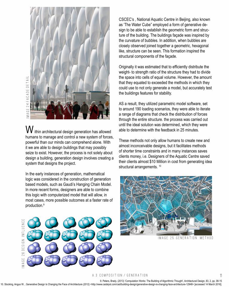
CSCEC’s , National Aquatic Centre in Beijing, also known as ‘The Water Cube” employed a form of generative de-sign to be able to establish the geometric form and struc-ture of the building. The buildings façade was inspired by the curvature of bubbles. In addition, when bubbles are closely observed joined together a geometric, hexagonal like, structure can be seen. This formation inspired the structural components of the façade.
Originally it was estimated that to efficiently distribute the weight- to strength ratio of the structure they had to divide the space into cells of equal volume. However, the amount that they equated to exceeded the methods in which they could use to not only generate a model, but accurately test the buildings features for stability.
AS a result, they utilized parametric model software, set to around 190 loading scenarios, they were able to iterate a range of diagrams that check the distribution of forces through the entire structure. the process was carried out until the ideal solution was determined, which they were able to determine with the feedback in 25 minutes.
These methods not only allow humans to create new and almost inconceivable designs, but it facilitates methods of shorter time constraints and in many instances saves clients money, i.e. Designers of the Aquatic Centre saved their clients almost $10 Million in cost from generating idea structural arrangements. 10
W ithin architectural design generation has allowed humans to manage and control a new system of forces, powerful than our minds can comprehend alone. With it we are able to design buildings that may possibly seize to exist. However, the process is not solely about design a building, generation design involves creating a system that designs the project.
In the early instances of generation, mathematical logic was considered in the construction of generation based models, such as Gaudi’s Hanging Chain Model. In more recent forms, designers are able to combine this logic with computerized model that will allow, in most cases, more possible outcomes at a faster rate of production.9
I m a
g e
2
4 f
a c
a d
e d
e t a
i l
I m a g e 2 5 g e n e r a t i o n m e t h o d
I m a
g e
2
6 d
e s
i g n
i
n f
l u
e n
c e
9. Peters, Brady. (2013) ‘Computation Works: The Building of Algorithmic Thought’, Architectural Design, 83, 2, pp. 08-1510. Stocking, Angus W. , Generative Design Is Changing the Face of Architecture (2012) <http://www.cadalyst.com/cad/building-design/generative-design-is-changing-face-architecture-12948> [accessed 14 March 2016].

A . 3 C O M P O S I T I O N / G E N E R A T I O N 12
is i l k p a v i l i o n
M e d i a t e d M a t t e r c a m b r i d g e , E N G L A N D 2 0 1 3
A3.2
I m a g e 2 7 s i l k p a v i l i o n
11. Peters, Brady. (2013) 12. Hu, Ray , A New Spin on Biomimicry in Architecture and Design: ‘Silk Pavilion’ by MIT MediaLab’s Mediated Matter Group (2012) <http://www.core77.com/posts/24986/> [accessed 14 March 2016].

A . 3 C O M P O S I T I O N / G E N E R A T I O N 13
G eneration has given designers the opportunity to be more explorative. They are able to be more efficient, and touch areas that have not been touched before. Essential-ly, generation design in the field of architecture opens up a world of possibilities.
Previously architects were required to compose the whole structure themselves. Nowadays we are able to use logi-cal and computational techniques to create something that might be considered ‘out of this world’. Using parametric modelling you can create a algorithmic recipe and instruct the computer to continuously perform this recipe and perhaps slightly change each time. In many instances, it can be a reflection of a biological process.11
The relationship between biological fabrication and gen-eration modelling was explored in the Silk Pavilion. The structure was inspired by the silkworm, whom the design-ers studied as they allowed them to construct their own 3D cocoons.
For the base of the construction the designers combined both computational modelling and the silkworms to com-plete the structure. They allowed the silkworms to create a scaffold of silk, spun at the base, over the non-woven components from the machine, established a reinforced structure across the gaps.
Not only were the silkworms affected by the constraints of the spatial arrangements, but the design team found that there were variations in light and heat, showing the silk-worms migration towards the darker and denser spaces.
Based on these observations the overall geometry of the pavilion, created by a Computer- Numerically Controlled Machine, was set to an algorithm that employed a single continuous thread.
However, the shortcomings to this approach, that may be applied to further generation process, is that it can be difficult to clarify were generation is still generation and not composition. In composition we change the structure based on computational data we receive rather than letter the computer find the optimal form from data.
In addition, many generation process are always genera-tion and morphing, there is never really a clear finishing. Only we are able to stop the process of generation and in some cases we may end the process for the ideal condi-tion is met.12
I m a g e 2 7 s i l k p a v i l i o n
I m a g e 2 8 s i l k p a v i l i o n d e t a i l
I m a g e 2 9 g e n e r a t i o n d e t a i l
I m a g e 3 0 d e s g i n i n f l u e n c e
11. Peters, Brady. (2013) 12. Hu, Ray , A New Spin on Biomimicry in Architecture and Design: ‘Silk Pavilion’ by MIT MediaLab’s Mediated Matter Group (2012) <http://www.core77.com/posts/24986/> [accessed 14 March 2016].

A . 4 C O N C L U S I O N 14
A cross Part A we have essentially be looking at con-ceptualization. This refers to an initialization of how we as designers consider the object that we construct and how we proceed to actually building that project.
Based on references of both the past and present there are instances in design where I believe we as humans have had success and failures. An achievement that I would specifically like to consider in my future design approach, is that of sustainability. Not only do I hope to create something that promotes this, but formalizes this creation in an equally sustainable way.
I believe it to be significant to design this way, as we are essentially designing for the future. Which not only bene-fits us, who currently inhabit this earth, but the generations to come.
Looking to nature is a means in which to influence this formation. In particular, I found interest through design generation that mimics natural formation. Perhaps through formation, where we use computation to find the optimal method, we can achieve a process that can provide the maximum benefits.
However, I would not consider this method as entirely innovative. Many people intend to design this way nowa-days as it is an approach to design futuring. Instead, I con-sider it to almost be a necessity and a common method of thinking, rather than a new or advanced method.
C o n c l u s i o n
A4
I m a g e 3 1 G r a s s h o p p e r m o d e l

A . 5 L E A R N I N G O U T C O M E S 15
I would like to say at this stage my experience with archi-tectural computing is a love – hate relationship. I constant-ly find it frustrating when a design doesn’t appear how I intend it to, yet when I manage to achieve something it is almost the best feeling in the world. I have a slight worry that it will only get worse from here.
My overall understanding of Grasshopper has increased significantly over the preceding weeks and I only intend to gain a greater knowledge as move forward. I believe that Grasshopper is a significant tool in many instances. Not only can it help me to generate my design, but it often offers a more convenient method than other forms of computation.
In past designs, I could have used grasshopper to create what many may consider to be one of the simplest things, contours. I believe it is important to consider the site in which you are designing and the topography is a signifi-cant element of this, especially because I was constantly being asked “have you consider the ground plane”. Finally, I have learnt through Grasshopper, how I can digitally model these contours to be able to present against my designs.
Another circumstance where I may have been able to utilize Grasshopper in a design, was through simply ex-ploring a range of possible design outcomes. Often it can be tiring and inconvenient to have to model each scenario. Yet, through simply baking a stage of your grasshopper component you almost instantly create a backlog of your design.
l e a r n i n g o u t c o m e s
A5
I m a g e 3 2 G r a s s h o p p e r m o d e l

16 A . 6 A L G O R I T H M I C S K E T C H E S
W e e k 2 - C u r v e i n t e r s e c t i o n s
W e e k 2 - C o n t o u r i n w i t h p l a n e s
W e e k 2 - t r a n s f o r m - m e s h & b o x m o r p h

17A . 6 A L G O R I T H M I C S K E T C H E S
I have found that with most things in life I am amazed by the simple things. And the simplistic aspect of Grasshopper is an instance where this occurs. It amazes me how such simple algorithms can be used to create quite complex structures. Even more so, how by changing a few simple points can completely alter the entire look of a structure.
In reference to what I consider to be my best sketches, I believe to be those that represent instances where a simple method of points was altered, or a complex geometry came from a not as complex set of components. I have also found great joy when inputs connected to outputs, especially when I attempted to create an irregular form.
Extending from the tutorials, for most sketches I aimed to establish a new form of geometry. Often this lead to unmatched outcomes or absurd for-mations. However, I found through trial and error that the best approach would soon be optimized.
As an example, the first sketch observed on the previous page, Transform – Mesh & Box Morph, I first trailed the use of different meshes that were to be set to various points of the rhino form. How-ever, it became apparent that the less structured
surfaces seemed to show fewer variations in size then the more abstract ones. A similar scenario was apparent in the following sketch, where the planar surfaces attached to a regular geometry was not as appealing as that of an irregular structure.
However, what I have found important in all of these structures is the concept of efficiency. As programs such as Grasshopper were developed, more imaginative architect became possible. These sketches can represent the simplicity behind creative ideas, yet also show each compo-nent at its complexity. Such as, the final sketch indicates a series of intersecting circles. However, by using Grasshopper I was able to locate the exact intercept points and formulate a connection between them that can be used to emulated a structural component.
Finally, I believe that these sketches demonstrate a form a modelling tool that allows designers to expand their mode of thinking. Using these plat-forms, it is ok to make mistake and try new things. The ability to easily manipulate the computerized models and patterns allows us to trial as many series until reach what we consider to be the per-fect one, or perhaps we can program the comput-er to determine the perfect outcome for us.
A L G O R I T H M I C S K E T C H E S
A5

P A R T A R E F E R E N C E S18
T E X T R E F E R E N C E S
archdaily , Aspen Art Museum / Shigeru Ban Architects (2014) <http://www.archdaily.com/546446/aspen-art-museum-shigeru-ban-ar-chitects> [accessed 8 March 2016].
archdaily, New Artist Residency In Senegal / Toshiko Mori (2015) < http://www.archdaily.com/608096/new-artist-residency-in-senegal-to-shiko-mori> [accessed 8 March 2016].
Architecture, Design & Planning, Sydney Uni-versity , Rachel Couper + Ivana Kuzmanovska: Mirador - Thursday Night Lectures(2013) <https://www.youtube.com/watch?v=Akvt7O5ZCCA> [accessed 14 March 2016].
Digital Design and Fabrication, Schools of Archi-tecture ,Honeycomb Morphologies - MATSYS (2004) <http://digitaldesignfabrication.blogspot.com.au/2011/03/honeycomb-morphologies-mat-sys.html> [accessed 14 March 2016].
Dunne, Anthony & Raby, Fiona (2013) Spec-ulative Everything: Design Fiction, and Social Dreaming (MIT Press) pp. 1-9, 33-45
Fry, Tony (2008). Design Futuring: Sustainability, Ethics and New Practice (Oxford: Berg), pp. 1–16
Gunther, David, Digital Fabrication leads the way in Sculptures by the Sea, Bondi. (2012) <http://sydney.edu.au/news/architecture/274.html?news-storyid=10399> [accessed 14 March 2016].
Hubarb, R, MATSYS (2013) <https://betweenlan-dandwater.wordpress.com/2013/02/05/matsys/> [accessed 14 March 2016].
Hu, Ray , A New Spin on Biomimicry in Architec-ture and Design: ‘Silk Pavilion’ by MIT MediaLab’s Mediated Matter Group (2012) <http://www.core77.com/posts/24986/a-new-spin-on-bi-omimicry-in-architecture-and-design-silk-pa-vilion-by-mit-medialabs-mediated-mat-ter-group-24986> [accessed 14 March 2016].
Kalay, Yehuda E. (2004). Architecture’s New Media: Principles, Theories, and Methods of Computer-Aided Design (Cambridge, MA: MIT Press), pp. 5-25
Kingsley, Gregory R. (2014). Aspen Art Museum Roof Structure: (USA-Golden), pp. 3 - 7
Oxman, Rivka and Robert Oxman, eds (2014). Theories of the Digital in Architecture (London; New York: Routledge), pp. 1–10
Peters, Brady. (2013) ‘Computation Works: The Building of Algorithmic Thought’, Architectural Design, 83, 2, pp. 08-15
Stocking, Angus W. , Generative Design Is Changing the Face of Architecture (2012) <http://www.cadalyst.com/cad/building-design/genera-tive-design-is-changing-face-architecture-12948> [accessed 14 March 2016].
The Thread Artist Residency , The Thread : The Building (2014) <http://www.thread-senegal.org/the-building/> [accessed 8 March 2016].
Volner, Ian, Senegal’s Cutting-Edge Artists’ Residency (2015) <http://www.wsj.com/arti-cles/senegals-cutting-edge-artists-residen-cy-1425589612> [accessed 8 March 2016].

P A R T A R E F E R E N C E S 19
I M A G E R E F E R E N C E S
IMAGE i NFORMATIONS, Grasshopper Modeling (2015) <http://www.nformations.com/> [accessed 15 March 2016].
IMAGE 7 archdaily , Aspen Art Museum / Shige-ru Ban Architects (2014) <http://www.archdaily.com/546446/aspen-art-museum-shigeru-ban-ar-chitects> [accessed 8 March 2016].
IMAGE 5 & 6 Kingsley, Gregory R. (2014). As-pen Art Museum Roof Structure: (USA-Golden), pp. 3 - 7
IMAGE 8 archdaily , Aspen Art Museum / Shige-ru Ban Architects (2014) <http://www.archdaily.com/546446/aspen-art-museum-shigeru-ban-ar-chitects> [accessed 8 March 2016].
IMAGE 11 – 13 archdaily, New Artist Residen-cy In Senegal / Toshiko Mori (2015) < http://www.archdaily.com/608096/new-artist-residen-cy-in-senegal-toshiko-mori> [accessed 8 March 2016].
IMAGE 14 The Thread Artist Residency , The Thread : The Building (2014) <http://www.thread-senegal.org/the-building/> [accessed 8 March 2016].
IMAGE 15 – 17 Digital Design and Fabrication, Schools of Architecture ,Honeycomb Morpholo-gies - MATSYS (2004) <http://digitaldesignfabri-cation.blogspot.com.au/2011/03/honeycomb-mor-phologies-matsys.html> [accessed 14 March 2016].
IMAGE 18 – 19 Gunther, David, Digital Fabri-cation leads the way in Sculptures by the Sea,
Bondi. (2012) <http://sydney.edu.au/news/archi-tecture/274.html?newsstoryid=10399> [accessed 14 March 2016].
IMAGE 20 – 22 Architecture, Design & Plan-ning, Sydney University , Rachel Couper + Ivana Kuzmanovska: Mirador - Thursday Night Lectures(2013) <https://www.youtube.com/watch?v=Akvt7O5ZCCA> [accessed 14 March 2016].
IMAGE 23 – 25 Stocking, Angus W. , Generative Design Is Changing the Face of Architecture (2012) <http://www.cadalyst.com/cad/building-de-sign/generative-design-is-changing-face-architec-ture-12948> [accessed 14 March 2016].
IMAGE 27 – 30 Hu, Ray , A New Spin on Biomimicry in Architecture and Design: ‘Silk Pavilion’ by MIT MediaLab’s Mediated Mat-ter Group (2012) <http://www.core77.com/posts/24986/a-new-spin-on-biomimicry-in-archi-tecture-and-design-silk-pavilion-by-mit-medial-abs-mediated-matter-group-24986> [accessed 14 March 2016].
IMAGE 31 Fablab El Paso , Essentials of Para-metric Modeling: Intro to Rhino + Grasshopper (2014) <http://fablabelpaso.org/event/essen-tials-of-parametric-modeling-intro-to-rhino-grass-hopper/> [accessed 17 March 2016].
IMAGE 32 The Proving Ground , Exercise 1: Space Truss Structure (2015) <http://wiki.theprov-ingground.org/usc-arch517-exercise1> [accessed 17 March 2016].

C O N T E N T S . C R I T E R I A D E S I G N 20

C O N T E N T S . C R I T E R I A D E S I G N 21
C O N T E N T S P A R T B : c R I T E R I A D E S I G N
B . 1 R E S E A R C H F I E L D 2 2 - 2 5
2 6 - 3 5
B . 3 C A S E S T U D Y 2 . 0 3 6 - 3 9
B . 2. C A S E S T U D Y 1 . 0
B . 4 T E C H N I Q U E : D E V E L O P M E N T 4 0 - 4 5
4 6 - 5 3
B . 6 T E C H N I Q U E : P R O P O S A L 5 4 - 5 5
B . 5 T E C H N I Q U E : P R O T O T Y P E S
r e f e r e n c e s
5 6 B . 7 L E A R N I N G O B J E C T I V E S & O U T C O M E S
5 7 B . 8 A P P E N D I X - A L G O R I T H M I C S K E T C H E S
5 8 - 5 9

B . 1 R E S E A R C H F I E L D 22
B.1R E S E A R C H F I E L D
t e s s e l a t i o n
13 . Microsoft, Tessellation Overview (2015) <https://msdn.microsoft.com/en-us/library/ff476340%28v=VS.85%29.aspx?f=255&MSPPError=-2147217396> [accessed 2 April 2016]14 . MathsIsFun.com, Tessellation (2014) <https://www.mathsisfun.com/geometry/tessellation.html> [accessed 2 April 2016].

B . 1 R E S E A R C H F I E L D 23
I m a g e 3 3 V o u s s o i r C l o u d | I w a m o t o S c o t t
Prior to my experience with Grasshopper and algorithmic modelling, I was aware of tessella-tion as a form of patterning used commonly in tiling and decorative elements of Islamic art and Ancient Roman Architecture. However, tessella-tion follows a mathematical order and the more complex the sequence, it may lead to a more interesting geometry.
The advancement of tessellation in computerised modelling overall allowed a more efficient design and construction process. In reference to a more efficient method, computerised tessellation per-mits for the dynamic subtraction and addition of
shapes to the overall form not only from its outer perspective but from within the geometric form.
A continuous boundary of a 3D form is represent-ed in computerized modelling by faces, edges and vertices surfaces. As it is difficult to manually analyse these forms, as they often intricate and complex, the 3D volume can be assessed with a mesh – in particular that of a tetrahedral or hexahedra form.
We are able to analyse through this method as each surface is given an individual mesh face with a distinct edge – which takes into account the original vertices. 13
13 . Microsoft, Tessellation Overview (2015) <https://msdn.microsoft.com/en-us/library/ff476340%28v=VS.85%29.aspx?f=255&MSPPError=-2147217396> [accessed 2 April 2016]14 . MathsIsFun.com, Tessellation (2014) <https://www.mathsisfun.com/geometry/tessellation.html> [accessed 2 April 2016].
B . 1 R E S E A R C H F I E L D 24
it e s s e l a t i o n
V o u s s o i r C l o u d I w a m o t o S c o t t , S a n F r a n s i s c o
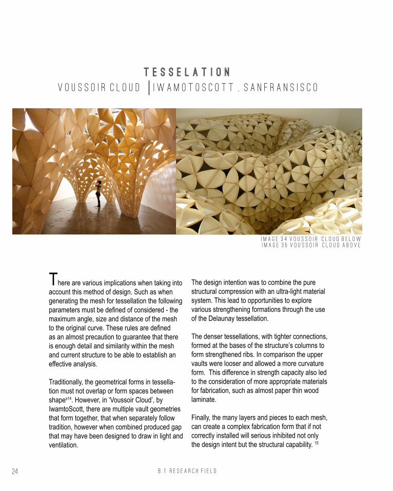
There are various implications when taking into account this method of design. Such as when generating the mesh for tessellation the following parameters must be defined of considered - the maximum angle, size and distance of the mesh to the original curve. These rules are defined as an almost precaution to guarantee that there is enough detail and similarity within the mesh and current structure to be able to establish an effective analysis.
Traditionally, the geometrical forms in tessella-tion must not overlap or form spaces between shapes14. However, in ‘Voussoir Cloud’, by IwamtoScott, there are multiple vault geometries that form together, that when separately follow tradition, however when combined produced gap that may have been designed to draw in light and ventilation.
The design intention was to combine the pure structural compression with an ultra-light material system. This lead to opportunities to explore various strengthening formations through the use of the Delaunay tessellation.
The denser tessellations, with tighter connections, formed at the bases of the structure’s columns to form strengthened ribs. In comparison the upper vaults were looser and allowed a more curvature form. This difference in strength capacity also led to the consideration of more appropriate materials for fabrication, such as almost paper thin wood laminate.
Finally, the many layers and pieces to each mesh, can create a complex fabrication form that if not correctly installed will serious inhibited not only the design intent but the structural capability. 15
I m a g e 3 4 V o u s s o i r C l o u d b e l o w
I m a g e 3 5 V o u s s o i r C l o u d a b o v e
15 . Archivenue, ‘Voussoir Cloud’ by IwamotoScott with Buro Happold (2009) < http://www.archivenue.com/voussoir-cloud-by-iwamotoscott-with-buro-happold/> [accessed 2 April 2016].16. Think Parametric, FERMID by Behnaz Babazadeh (2011) < http://designplaygrounds.com/deviants/fermid-by-behnaz-babazadeh/> [accessed 2 April 2016].

B . 1 R E S E A R C H F I E L D 25
it e s s e l a t i o n
F E R M I D B e h n a z B a b a z a d e h
A typical method in tessellation is the repeti-tion of heterogeneous elements to define a whole homogenous element. In Fermind, by Behnaz Bahazadeh a series of white curls are overlaid and connected together to form an almost living organism. The curvature of the form allows an or-ganic, yet mechanical movement that is so subtle and deceptively simple.
The opportunities created when using a singular heterogeneous form leads to a more efficient fabrication process. As the same element can be generated as many times as necessary, without manipulation of form. However, it becomes more difficult in the process of combining these iden-
tical elements to create the overall form. This is due to the way the pieces connect. To be able to create an 3D interesting form each identical piece follows its own direction and angle. Although this may be maintainable in computerised- design when manually fabricating the design (as Bahaz-adeh demonstrated) it requires precise and often time-consuming alterations 16
Overall, tessellation allows for a diverse range of geometry formations. The method through finding these forms can be both singular in reference to one repeating element or unique, where many different forms make up the overall picture.
I m a g e 3 4 V o u s s o i r C l o u d b e l o w
I m a g e 3 5 V o u s s o i r C l o u d a b o v e
I m a g e 3 6 f e r m i d o v e r a l l s t r u c t u r e
I m a g e 3 7 f e r m i d c l o s e u p d e t a i l
15 . Archivenue, ‘Voussoir Cloud’ by IwamotoScott with Buro Happold (2009) < http://www.archivenue.com/voussoir-cloud-by-iwamotoscott-with-buro-happold/> [accessed 2 April 2016].16. Think Parametric, FERMID by Behnaz Babazadeh (2011) < http://designplaygrounds.com/deviants/fermid-by-behnaz-babazadeh/> [accessed 2 April 2016].

B .2 c a s e s t u d y 1 . 0 26
B.2c a s e s t u d y 1 . 0
t e s s e l a t i o n V O L T A D O M i
17. Think Parametric, FERMID by Behnaz Babazadeh (2011) < http://designplaygrounds.com/deviants/fermid-by-behnaz-babazadeh/> [accessed 2 April 2016].18. Luis Pina Lopes, Voltadom by Skylar Tibbits | Skylar Tibbits (2011) <http://www.arch2o.com/voltadom-by-skylar-tibbits-skylar-tibbits/> [accessed 5 April 2016].

B .2 c a s e s t u d y 1 . 0 27
I m a g e 3 8 V o l t a d o m s k y l a r t i b b i t s
The Voltadom is installation that occupies a concrete and class hallway in MIT, as a part of a 150th year celebration of FAST Arts Festival (Fes-tival of Arts, Science and Technology). Created by the studio SJET, founded by Skylar Tibbits aims to embed a multifaceted studio approach where they establish a research platform for computing and experimental design.
The Voltadom, is characteristically reminiscent in is constructive appeal to the historical vaults in gothic cathedrals. The oculi, often seen at the top of gothic cathedrals, is utilized across the installation as a way of limiting light and views of the outside.
Voltadom expands on the architectural practice of panel surfaces. They aimed to increased the depth of dual vaulted surface with the ability for efficient manufacture and fabrication.17
The use of tessellation was manipulated to pro-cess single strips of materials that would be bent to achieve the complex vault surface.
The use of tessellation was manipulated to pro-cess single strips of materials that would be bent to achieve the complex vault surface. In addition, the installation utilizes tessellation as a means to multiply and grow, as a cell group would, with in-dependence¬¬ of each cell however with connec-tions remaining to establish a solid boundary. 18
17. Think Parametric, FERMID by Behnaz Babazadeh (2011) < http://designplaygrounds.com/deviants/fermid-by-behnaz-babazadeh/> [accessed 2 April 2016].18. Luis Pina Lopes, Voltadom by Skylar Tibbits | Skylar Tibbits (2011) <http://www.arch2o.com/voltadom-by-skylar-tibbits-skylar-tibbits/> [accessed 5 April 2016].
B .2 c a s e s t u d y 1 . 0 28
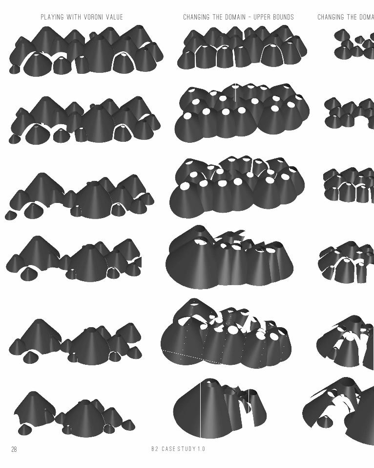
p lay i n g w ith voron i va lu e c hang i n g th e d oma i n - u p p e r b ounds chang i n g th e d oma i n - l ower bounds

B .2 c a s e s t u d y 1 . 0 29
c hang i n g th e d oma i n - l ower bounds chang i n g th e h e i g ht o f ov era l c on e p lay i n g w ith tr imm i n g h e i g ht

B .2 c a s e s t u d y 1 . 0 30
c hang i n g tr imm i n g va lu e o f
i d e e nt i ca l c on es
Subst i tut i n g s e cond con e g e ometry
f or cy l i n d e r
Subst i tut i n g on e c on e g e ometry
f or cy l i n d e r
S u bst i tut i n g a l l c on e g e ometry
cy l i n d e r and tr imm i n g
Subst i tut i n g a l l c on e g e ometry
cy l i n d e r and tr imm i n g

B .2 c a s e s t u d y 1 . 0 31
S u bst i tut i n g A l l c on e g e ometry f or
cy l i n d e rs
S u bst i tut i n g on e c on e g e ometry f or
cy l i n d e rs and on e c on e g e ometry f or s ph er e &
tr imm i n g
S u bst i tut i n g on e c on e g e ometry f or
cy l i n d e rs and on e c on e g e ometry f or s ph er e
c hang i n g o rd er o f cy l i n d e r and s ph er e g e ometry
Subst i tut i n g A l l c on e g e ometry
f or s ph er e s
S u bst i tut i n g s e cond con e g e ometry
f or cy l i n d e r
Subst i tut i n g on e c on e g e ometry
f or s ph er e
Subst i tut i n g on e c on e g e ometry f or
cy l i n d e rs and on e c on e g e ometry f or s ph er e
c hang i n g o rd er o f cy l i n d e r and s ph er e g e ometry

B .2 c a s e s t u d y 1 . 0 32
Array over c urves & c hang i n g
array ang l e s
Array over s ph er e Array over cy l i n d e r
& tub e

B .2 c a s e s t u d y 1 . 0 33
B.2c a s e s t u d y 1 . 0
V O L T A D O M s U C C E S S F U L O U T C O M E S i
I m a g e 3 9 V o l t a d o m s k y l a r t i b b i t s
1 2 3 4
B .2 c a s e s t u d y 1 . 0 34
B.2c a s e s t u d y 1 . 0
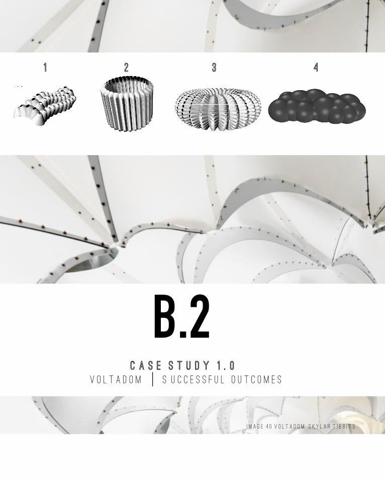
I m a g e 4 0 V o l t a d o m s k y l a r t i b b i t s
iV O L T A D O M s U C C E S S F U L O U T C O M E S
1 2 3 4

B .2 c a s e s t u d y 1 . 0 35
I m a g e 4 0 V o l t a d o m s k y l a r t i b b i t s
Being still relatively new to Grasshopper I was apprehensive about this task and how I would approach it. I first began playing with the case study by manipulating each of the sliders. This allowed me to gain an understanding of how each component became a part of the design and how it was significant. However, I found that although this may alter the design overall it’s impact was not crucial to manipulating the intent of the design. Nonetheless I found that there were same iterations more favorable then others for this design. For example, when using the populate 2D function, it is more beneficial to have a higher points value for the N input. As the lower value created less intersections and this impacted the amount of trimming of the cones later in the process. It also became apparent that the width and height of the cones could impact the trimming process and either this would limit the cones from toughing or change the size of the hole that was cut in the cone.
However, I aimed to further explore this case study by subsisting to the cone geometry for others shapes, such as cylinders & spheres. As there were two cone components used in the Grasshopper file I manipulated with how the cones could be incorporated with these shapes, or how these shapes may function on there own. In some instances, I found the shapes to create a texture like geometry, or others created curved surfaces that may be replicated as walls.
The final challenge I undertook was manipulating the way the pattern was arrayed across I surface. I initially played with how the points were populat-ed, changing from a 2D to a 3D form. Following this I used various 2D geometries that allowed me to arranged the cones in any form rather than a rectangle. However, I mainly wanted to achieve arraying the cones over a surface shape and I found this achievable by manipulating both Grasshopper and Rhino files.
Selection Criteria: In regards to what I was trying to achieve with these iterations I was looking to create a form that was practical (in reference to
its fabrication), poetic (in form), solid (able to with-stand its own shape) & efficient (through repeat-ing elements). Although, the 4 chosen iterations may not reference all of these criteria, I believe elements from each of them can be manipulated together to generate an overall ideal form.
Iteration 1, was successful as I considered it an efficient process, the repeating elements meant that generating the form was fast and may lead to an efficient fabrication process. However, due to the irregular curved shape, fabrication may not be as manageable without additional joining elements. Iteration 2 & 3, was successful as I believed these to be solid forms. When fabricated these elements would be able to exist as them-selves without support. Finally, iteration 4 was successful as I found its form to be poetic. The repeating spheres generate a bubble texture that could be manipulated to a particular geometry.
There are many different qualities that can be achieved with this installation. Due to the holes throughout the shape, light and views is one major aspect. In addition, changing the size of the wholes across the form ca manipulate what views are accessible and how much light. Are darker space can produce a significantly different experience to a laminated space.
In regards to an effected created by this form, is a textured look. This can be achieved by either manipulated the spheres across a surface, or perhaps using the cones and changing the direc-tion that they are arrayed to create a scale (like a reptile) appeal.
In regards to other forms, surfaces of spaces that could be form I would look at one of the iterations that combined cylinders in place of cones. This created a curved surface plan, when extruded these component may be manipulated as walls. Further more Iteration 4 could be arrayed onto this surfaces to give it a textured element. Or per-haps a pavilion could be constructed with more repeating elements on a larger surface similar to iteration 1.

B .3 c a s e s t u d y 2. . 0 36
B.3c a s e s t u d y 2 . 0
r E V E R S E - E N G I N E E R G A R D E N S B Y T H E B A Y i
19. Gardens By The Bay , FASCINATING FACTS ABOUT THE ICONIC SUPERTREES (2012 ) <http://www.gardensbythebay.com.sg/en/the-gardens/supertree-grove/facts-and-figures.html> [accessed 12 April 2016].20. Grant Associates, Gardens By The Bay (2012) <http://www.grant-associates.uk.com/projects/gardens-by-the-bay/> [accessed 12 April 2016].

B .3 c a s e s t u d y 2 .. 0 37
Gardens by the Bay was designed by Grant Associates architects, in Singapore, 2012. It acts as a “blend nature, technology, environmental manage-ment and imagination to create a 21st century focus for tropical horticulture and a unique destination experience” (Gardens By The Bay, 2012).
The Supertree is a particular element in this garden. There are 18 in total ranging from 25 – 50m in height. Acting as vertical gardens, 11 of the trees are embedded with canopies that employ sustainability functions, while the rest act as inverted umbrellas. These canopies provide shade during the day and provide light during the night. Creating an exhilarat-ing space of visual and sounds affects. 19
Furthermore, each tree is reinforced with a concrete core, which upholds the vertical steel frame trunk
of the Supertree. For each tree there are a series of plants attached to the steel frame, to withhold these plants, planting panels are installed on the trunk. Essentially this creates a living skin, similar to the live nature of real trees. Finally, photovoltaic cells are attached to harvest the solar energy which will aid in lighting up the canopies. For the remaining trees, air exhaust receptacles are achieved through cooled conservatories.
Although the trees may not appear directly as nat-ural elements, the incorporation of living materials and design inspired by nature, established the blend of technology with the natural. Furthermore, they established their intent to include environ-mental management by using sustainability mate-rials and practices. Finally, its overall appearance t surely offers a unique experience.20
I m a g e 4 1 g a r d e n s b y t h e b a y
19. Gardens By The Bay , FASCINATING FACTS ABOUT THE ICONIC SUPERTREES (2012 ) <http://www.gardensbythebay.com.sg/en/the-gardens/supertree-grove/facts-and-figures.html> [accessed 12 April 2016].20. Grant Associates, Gardens By The Bay (2012) <http://www.grant-associates.uk.com/projects/gardens-by-the-bay/> [accessed 12 April 2016].

B .3 c a s e s t u d y 2. . 0 38
i
C a s e s t u d y 2 . 0
R e v e r s e - e n g i n e e r g a r d e n s b y t h e b a y
I m a g e 4 2 s u p e r t r e e s
I m a g e 4 3 s u p e r t r e e s
s t e p o n e s t e p t w o s t e p t h r e e s t e p f o u r
graph mapp er
L i n e d i v i d e c i r c l e
mu lt i p ly d i v i d e
f l i p p L i n e
j i tt er
sh i ft
conmesh
bas i c d i a gram o f parametr i c too l p roc essnote not a l l c ompon ents s hown

B .3 c a s e s t u d y 2 .. 0 39
I m a g e 4 2 s u p e r t r e e s
I m a g e 4 3 s u p e r t r e e s
P Undertaking this process, I was a little skeptical at first that I would be able to achieve it. As I had a design in mind for my final project I searched around to find examples of vase as this was the particular shape I was intending to in-clude in my design. I found a script that employed the component of graph mapper. This utilized points and lines that I mapped onto circles that could be manipulate by a slider, to affect the width of each circle. I then was able to divided each cir-cle into the same amount of points. I however, the next step difficult to join each of the points verti-cally as when a poly line component was added it we joined the points into circles. With help I found that the process was easy and all I had to do was flip the value of each point. Therefore, rather then every point in the circle having the same value, the first point divided of each circle was identical and so on.
To create the tree like components I randomly connected the points by jittering the values. Similar to create the lines which wrap around the tree I used a component to shift the data values of each points.
To create the inner concrete section, I used a mesh that was laid upon each of the points.
However, I reduced the circle of the circles and the amount so that this cone figure sat within the frame figure.
In regards to the outcome of this process I consider the overall concept of my reverse engineer is similar to the actual Supertrees, this includes the overall form of the steel frame and the concrete core. However, the precise branches and shape of the steel frame and concrete core my differ to what I have designed. When looking at images it appears that the base is widen, which would be ideal for stability and the canopies are wider and start early from the trunk. This feature may have been created for better shade.
To take this design further I would like to see how I could integrate the canopies and the planting panels that were utilized in the design to be able to establish the design intent to have an environmentally manageable design. Within my reverse engineering I have only created the trunk and concrete inside. To be able to establish the additional more complex parts I would need to un-dertake further research. However, other methods I could take from this design would be to see how the structural frame and concrete column (which I have established with a mesh) could be re-formed into another shape or into fractions of the original form.
s t e p f i v e f i n a l

B 4 t e c h n i q u e d e v e l o p m e n t 40
B.4T E C H N I Q U E D E V E L O P M E N T
I T E R A T I O N M A T R I X G A R D E N S B Y T H E B A Y i

B 4 t e c h n i q u e d e v e l o p m e n t 41
Looking back to B2 the selection criteria that I was interested in was a form that was practical. By this I mean something that can be fabricated easily and efficiently. Something that is poetic in form.
In reference to this criterion I want to design something that will evoke a response from the viewer or user. However, the poetic form does not necessarily have to be something that is appeal-ing to the eye. I believe something that is harsh will also establish a poetic response, perhaps a negative one.
The third criteria were that the design is to be sol-id. It a form is not able to withstand its own shape external elements are required. However, a solid
form can be achieved in many ways, it doesn’t particularly have to be form that is solid. Instead I considering something solid to have strength and stability.
Finally, the last criteria I was interested in was a form that was efficient. However, not in the means of fabrication entirely. Through the repletion of elements this can lead to a more appealing design through pattern. In regards to these repeating elements this can also lead to efficiency in fabrication as programs are not required to create changing elements instead just multiples of a single element. This may also make assem-blage of materials easier as one does not need to understand how different elements join but rather how do the same elements join.
I m a g e 4 4 g a r d e n s b y t h e b a y

B 4 t e c h n i q u e d e v e l o p m e n t 42
c hang i n g ov era l g e ometry
sect i o n i n g g e ometry
chang i n g f rame and concr et e mesh s e p e rate ly
array & M i r ror i n g ov era l f orm

B 4 t e c h n i q u e d e v e l o p m e n t 43

B 4 t e c h n i q u e d e v e l o p m e n t 44
B.4T E C H N I Q U E D E V E L O P M E N T
S U C C E S S F U L O U T C O M E S G A R D E N S B Y T H E B A Y i
I m a g e 4 5 g a r d e n s b y t h e b a y

B 4 t e c h n i q u e d e v e l o p m e n t 45
Using my criteria has influence for my itera-tions, I was mainly interested in the overall form of the design. Therefore, I tested the design for overall form changes including the frame and mesh. Secondly I manipulated the form in sec-tions to see how it would act in different compo-nents. Thirdly, I mainly manipulated the mesh in both the vertical and horizontal form. and finally, I played with the repetition of elements.
With the brief in mind, I aimed manipulating some iterations to a particular form. With my current skills to be able to achieves this I baked certain parts of the script so that it would stay in place while I manipulate and moved other sections through grasshopper. For me so far I found this to be a manageable process as it did not necessari-ly take an excessive amount of time.
From these iterations I was able to selected four that I considered to not necessarily be the most successful in regards to my selection criteria, but more so the most interesting.
Iteration 1 interested me as rather than demon-
strating the branches of a tree, to me it appeared as if the shape became the trunk and the roots. To create this, I mirrored the shape, after flipping it, along a curve. in terms of criteria this would demonstrate an efficient process through repeti-tion.
Iteration 2 was selected as I found the form to be interesting. Although using the same grasshopper script to create it as my reverse engineer, I found that it looked distinctively different. It was an interesting form as there is a blend of the shapes curve and almost repetition curve at the bottom and top.
Iteration 3 and 4 were both selected because, although very similar to the reverse engineer shape, it believed that they could act as a com-pletely different process.
Overall though, I considered this process to be something that would not necessarily be the easiest and most efficient form to fabricate. Which would lead to time and money costs and these are something I would like to consider in my design.
I m a g e 4 5 g a r d e n s b y t h e b a y
4321

B 5 T E C H N I Q U E P R O T O T Y P E S 46
B.5T E C H N I Q U E : P R O T O T Y P E S
p r e c e d e n t s s t a c k i n g & g u y i n g i
I m a g e 4 6 s t a k i n g & g u y i n g
p h ot o t a k e n b y t a y l a h p a r k e r
21 Merri Creek Management Commitee, Merri Park Wetlands (2009) <http://www.mcmc.org.au/file/Site_notes/MCMC%20-%20Merri%20Park%20Wetland%20web%20version.pdf> [accessed 19 April 2016].22. University of Nebraska, Care of Newly Planted Trees () <http://nfs.unl.edu/documents/communityforestry/Storm%20Damage%209%20-%20Care%20of%20Newly%20Planted%20Trees.pdf> [accessed 19 April 2016].
B 5 T E C H N I Q U E P R O T O T Y P E S 47
When I approached the site I found myself considering designing and being able to fabricate at a 1: 1 scale. Therefore, I didn’t necessarily work around site thinking about large things to design. I often found myself looking towards the ground. Interesting I noticed the staking and guarding of trees. This is something that I have definitely seen before however, I began to really consider the overall design and purpose of it.
Upon further research after visiting the site, I found out that the wetlands in the Merri Park area, on the Merri Creek Trail, are constantly under maintenance. And it is only because of the dedicated to volunteers that the wetlands are able to exist in the condition that they do today. However, currently ‘Less than 4% of the original wetland area remains … and it is mostly in very poor condition’ (Merri Creek Management Com-mittee, 2009).
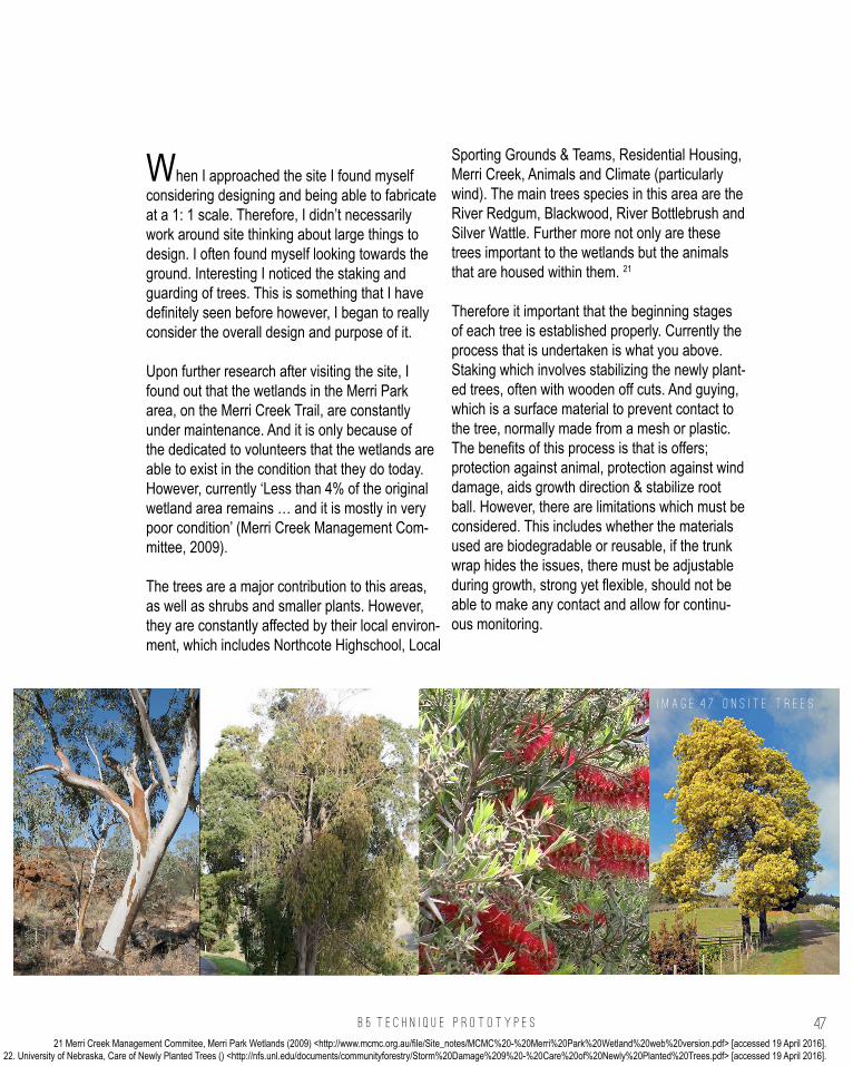
The trees are a major contribution to this areas, as well as shrubs and smaller plants. However, they are constantly affected by their local environ-ment, which includes Northcote Highschool, Local
Sporting Grounds & Teams, Residential Housing, Merri Creek, Animals and Climate (particularly wind). The main trees species in this area are the River Redgum, Blackwood, River Bottlebrush and Silver Wattle. Further more not only are these trees important to the wetlands but the animals that are housed within them. 21
Therefore it important that the beginning stages of each tree is established properly. Currently the process that is undertaken is what you above. Staking which involves stabilizing the newly plant-ed trees, often with wooden off cuts. And guying, which is a surface material to prevent contact to the tree, normally made from a mesh or plastic. The benefits of this process is that is offers; protection against animal, protection against wind damage, aids growth direction & stabilize root ball. However, there are limitations which must be considered. This includes whether the materials used are biodegradable or reusable, if the trunk wrap hides the issues, there must be adjustable during growth, strong yet flexible, should not be able to make any contact and allow for continu-ous monitoring.
I m a g e 4 6 s t a k i n g & g u y i n g
p h ot o t a k e n b y t a y l a h p a r k e r
I m a g e 4 7 o n s i t e t r e e s
21 Merri Creek Management Commitee, Merri Park Wetlands (2009) <http://www.mcmc.org.au/file/Site_notes/MCMC%20-%20Merri%20Park%20Wetland%20web%20version.pdf> [accessed 19 April 2016].22. University of Nebraska, Care of Newly Planted Trees () <http://nfs.unl.edu/documents/communityforestry/Storm%20Damage%209%20-%20Care%20of%20Newly%20Planted%20Trees.pdf> [accessed 19 April 2016].
B 5 T E C H N I Q U E P R O T O T Y P E S 48
B.5T E C H N I Q U E : P R O T O T Y P E S
p r e c e d e n t s m a t e r i a l s i
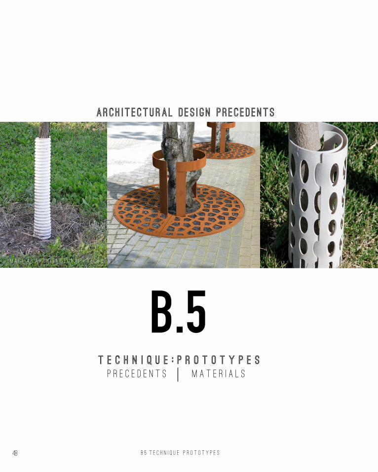
arch itectural des ign precedents
24. Nova, The future of plastics (2015) <http://www.nova.org.au/earth-environment/future-plastics> [accessed 27 April 2016].25. ePlastics, Lexan Polycarbonate Film (2016) <http://www.eplastics.com/film_thin_sheets> [accessed 27 April 2016].
I m a g e 4 8 a r c h i t e c t u r a l p r e c e d e n t s

B 5 T E C H N I Q U E P R O T O T Y P E S 49
The current design used for tree protection is limited in appearance and its extra potential. By this I mean, I believe that this form of guard can also aid the trees growth by capturing water. There are two ways that this could be achieved, the first is through the design itself. Using tubes at the end of the guard may be able to draw water directly to the routes of the plants. However, this may damage the roots as the may struggle to move around the tubes or attach to them. Then when they guards is removed it was essentially remove the roots straight out of the ground, damaging the tree.
The other method is to use a particular material that is able to capture the water. The material could either absorb water moisture and gradually release it or use a bump surface to slow down the waters descent to the roots. This slower descent would help to not over hydrate the plant and allow the process to be gradual. Research states that “surfaces with asymmetric bumps significantly in-crease water droplet” collection (Prakash, 2016).
Another property of the material would be whether it is biodegradable or able to be reused. Polyhydroxalkanoate is a type of plastic that is commonly found in everyday items that we may
use, such as food packaging and even medical implants. It is fully biodegradable under the cor-rect conditions and offer a non-toxic guarantee, which is ideal for the plants growth and long-life ability. It is created by specific strains of bacteria that is exposed to essential nutrients, such as oxygen and nitrogen. Furthermore, the production of this plastic around the world is only growly exponentially as the years go on (see figure 1). 24
The other form of material, water absorption is not as established as biodegradable materials. And the materials that we would find are costly and time consuming in fabrication, due to under development. However, instead of using a plastic that absorbs water, as started early we could use one that has a textured surface to decrease the water movement. A specific material that may be utilized is Lexan Polycarbonate Film.
At less than $1 for a 24 x 48 inch sheet, it is generally cheap material, that offers a textured finished and flexibility – which are two of the keys requirements for this material component. In addition, the strength of the polycarbonate film allows for heat resistance, toughness and rigidity. Which follows the criteria of a solid form that I was intending to quantify in the design. 25¬
F I G U R E 1
24. Nova, The future of plastics (2015) <http://www.nova.org.au/earth-environment/future-plastics> [accessed 27 April 2016].25. ePlastics, Lexan Polycarbonate Film (2016) <http://www.eplastics.com/film_thin_sheets> [accessed 27 April 2016].
i m a g e 4 9 t e x t u r e p l a s t i c

B 5 T E C H N I Q U E P R O T O T Y P E S 50

B 5 T E C H N I Q U E P R O T O T Y P E S 51

52

B 5 T E C H N I Q U E P R O T O T Y P E S 53
Inspired by my reverse engineering process I looked to fabricate how the different wire framed components could be joined together. I also observed how you could break up the wire com-ponents into separate smaller pieces which would then allow for a more irregular shapes.
Affect trying to achieve from selection criteria From my selection criteria the two methods I aimed to establish was the ease in fabrication and the stability of the design. Therefore, I consider the best approach to start was to consider how the components of the wire frame were joined together. Basic plumber joints use angled joints that I considered to similar to my intent. I took this as inspiration in creating a T-joint, a slightly curved single joint, cross joint and an irregular 4 ways joint. The main joints can be observed above. The single joint is crucial to combine the vertical elements together, whereas the remain joints not only help the horizontal elements to join but it allows these framing members to join with the horizontal ones.
My process of fabrication to test this was by using grasshopper to model the frame and layer out each frame component. In then joined each piece using plasticine, however, the material although cheap and mouldable, is time consuming in the drying process, and therefore left limitations to the design angles changing as the piece would gradually slide down. the next step in this process would be to construct the joints in rhino and 3d print them for created strength and stability.
The mesh skin was establish again by flattening the piece in Grasshopper and Rhino and then printing it out on a sheet to then overlay on the plastic, this allowed me to gain a more accurate precision of where the mesh would overlap with the frame. Printing directly onto the plastic would be the next step as this one allow one less obsta-cle in trying to obtain exact dimensions.
This process helped me to inform my digital mod-el as it allowed me to consider which connections in the wire frame would work and which would not. I found that by increasing the angle of the piece connections lead to a more difficult fabrica-tion. As I intend to have an efficient fabrication I wanted to create the optimal angle, and therefore decreased this value. Furthermore, by creating the wireframe I was able to observe how this would interact with the mesh. As I am intending to use the mesh as a plastic wrap (something to protect the tree as it grows) it is ideal for this to content to the frame, so that it does not move about.
As I previously mentioned that strength is a factor that I consider to be important. This is particu-larly important as the tree relies on the staking elements for stability, therefore the method that I have currently undertaken failed when I applied pressure to the frame. Although not entirely suc-cessful, I believe with the correct elements that the design would be more practical.
i m a g e 4 9 f a b r i c a t i o n j o i n t c o n n e c t i o n s

B 6 t e c h n i q u e : p r o p o s a l 54
B.6T E C H N I Q U E : P R o p o s a l
M e r r i c r e e k t r e e p r o t e c t i o n i

B 6 t e c h n i q u e : p r o p o s a l 55
Based on my exploration and research my design proposal is to establish a form of tree protection in its early stages of development. This is to help ensure the growth of the wetlands in Merri Park. With this design I do not intend to only benefit the trees. By allowing better tree growth this establishes homes for animals (i.e. birds), and by better protection may assist the volunteer community in the conservations of the park.
This technique can be applied to almost any-where on site. From my observations on site, it appeared that most areas where new trees were planted were on the outskirts of each bush path. A limitation to my design is that it does not consider unstable ground. The angle and the soil for which the protection barrier sits on may hinder its strength in defending from the climate and animals. It may also pose a threat to the tree if it falls, as the tree should not be touched in its initial growing stage. Therefore, at this stage the design is best suited to areas on site where the ground is stable and the soil is level. However, as most of the trees native to the site do not sit
on the rivers edge (the steepest areas), this may actually not act as an issue. Nonetheless is pays to be cautious.
In regards to what is innovative about the design, I do not consider the design itself. This is because visual it looks relatively simple and not particu-larly unique. However, I believe the proprieties of this design are different to the current products being used. I intend to be able to draw water to the roots of the trees, helping to establish greater growth capacity. As the area is on a gradual slope to the river, most water runs away from the plants, and therefore we must be able to capture as much as possible.
Another drawback to this design is that currently there are many pieces to it. As a have decided to create the frame as something that can be recy-cle it would be practical to have it easily assem-bled. Perhaps if the entire frame initially comes in separate pieces, but once established it can be utilised by different trees by simple breaking it into two halves.

B . 7 L E A R N I N G O U T C O M E S 56
Throughout this process I have been able to develop my skills in being able to utilise grasshopper and not only manipu-late and existing file but create my own file and further manip-ulate it. I found that through investigate the geometry and the way that each component worked together that I was able to utilize Rhino and Grasshopper to establish an investigation of the design. One process that I have particularly enjoyed was manipulating the files under a type of series. Through this I was able to observe how small changes could have a large impact on the design. This process can be observed in both my design matrices from B.2 and B.4.
As a result of these process have been able to further develop my design computational skills. I was nervous at first when I would even be considering creating my own design. But I have learnt that ideally nothing is purely unique. I was able to learn from other scripts and utilise them together to create something that I considered different or unique in it’s own right. However, I know that my skills are still in process and I hope to further refine them.
Being able to use digital tools to make the creattions that I designed come to life was also an interesting experience. Although some aspects I failed at this approached, I believe there are further techniques I looked forward to exploring.
When it came to proposing my design, I tried to considering the brief and site before allocating my desired approached. I believed that these were fundamental factors as when design-ing for a client they are essentially the reason for your work. By looking at all sides to the site, both its strengths and weakness I was able to establish what I considering to not only be an interesting approached but a necessity
Research on both the site, materials and techniques that I aimed to utilised also aided me in created an established design. Although, my process is yet to be completed and I look forward to fully developing it in the future.
l e a r n i n g o u t c o m e s
B7
W e e k 5 P A T H M A P P E R
W e e k 7 d e s i g n p r o p o s a l

5757 A . 6 A L G O R I T H M I C S K E T C H E S
For this section of the course I aimed to change the scripts as much as possible from what was given to me in files or from the videos. Further more I played around with adding scripts that I found online with things that I made or with things from the tutorial videos. The main approach I took to this was inputting new geometries to the scripts. However, I found that the more complex the geometry the likelihood that it didn’t or the the Grasshopper image would become overbearing and super intricate.
The biggest obstacle in this process wasn’t actually the files, but the strength of my computer. It was constantly crashing and taking a while to create what I thought was simple changes. This forced me to not only randomly selected values and shapes, but to actually considering what I was inputting and how it would impact the shape.
However, I still find myself interested in how the simple things can make big changes, often this occurs when I play around with mesh and sliders.
The first image below is from exploration for my design proposal. After creating two from various vectors and polylines, rather than keeping the smooth mesh surfaces I plugged this into a a De-launay mesh component which created a range of interesting edges. However, I moved on from this shape as I found it to difficult in the fabrica-tion process and also off the course of what I was aiming to achieve with my design.
The second image is from a tutorial video, where we manipulated lists and trees. However I changed the script from where the panels of the sphere surfaces were once joints to having the protruding at various angles. And the final image involves graphing various sections. However, I found myself more interested to what these kind of design appeared as and what it could lead to. When I look at it I think of something under the sea, and therefore I believe it could related to a pavilion or shelter of some sort that is positioned by the sea.
A L G O R I T H M I C S K E T C H E S
B8
W e e k 7 d e s i g n p r o p o s a l W e e k 5 - T R E E M E N U W e e k N T P G R A P H I N G S E C T I O N S

P A R T B r E F E R E N C E S 58
T E X T R E F E R E N C E S
Archdaily, Gardens By The Bay (2012) <http://www.archdaily.com/254471/gardens-by-the-bay-grant-associates> [accessed 12 April 2016].
Archivenue, ‘Voussoir Cloud’ by IwamotoScott with Buro Happold (2009) < http://www.ar-chivenue.com/voussoir-cloud-by-iwamotoscott-with-buro-happold/> [accessed 2 April 2016].
ePlastics, Lexan Polycarbonate Film (2016) <http://www.eplastics.com/film_thin_sheets> [accessed 27 April 2016].
Gardens By The Bay , FASCINATING FACTS ABOUT THE ICONIC SUPERTREES (2012 ) <http://www.gardensbythebay.com.sg/en/the-gar-dens/supertree-grove/facts-and-figures.html> [accessed 12 April 2016].
Grant Associates, Gardens By The Bay (2012) <http://www.grant-associates.uk.com/projects/gardens-by-the-bay/> [accessed 12 April 2016].
Luis Pina Lopes, Voltadom by Skylar Tibbits | Skylar Tibbits (2011) <http://www.arch2o.com/voltadom-by-skylar-tibbits-skylar-tibbits/> [ac-cessed 5 April 2016].
Manu Prakash, ‘Wetting: Bumps lead the way’, Natural Materials , 15, (2016), 378–379.
MathsIsFun.com, Tessellation (2014) <https://www.mathsisfun.com/geometry/tessellation.html> [accessed 2 April 2016].
Merri Creek Management Commitee, Merri Park Wetlands (2009) <http://www.mcmc.org.au/file/Site_notes/MCMC%20-%20Merri%20Park%20Wetland%20web%20version.pdf> [accessed 19 April 2016].
Microsoft, Tessellation Overview (2015) <https://msdn.microsoft.com/en-us/library/ff476340%28v=VS.85%29.aspx?f=255&MSPPEr-ror=-2147217396> [accessed 2 April 2016].
Nova, The future of plastics (2015) <http://www.nova.org.au/earth-environment/future-plastics> [accessed 27 April 2016].
Think Parametric, FERMID by Behnaz Babaza-deh (2011) < http://designplaygrounds.com/devi-ants/fermid-by-behnaz-babazadeh/> [accessed 2 April 2016].
University of Nebraska, Care of Newly Planted Trees () <http://nfs.unl.edu/documents/commu-nityforestry/Storm%20Damage%209%20-%20Care%20of%20Newly%20Planted%20Trees.pdf> [accessed 19 April 2016].

P A R T B R E F E R E N C E S 59
I M A G E R E F E R E N C E S
IMAGE 33 Architizer, Voussoir Cloud (2008) <http://architiz-er.com/projects/voussoir-cloud/> [accessed 2 April 2016].
IMAGE 34 Architizer, Voussoir Cloud (2008) <http://architiz-er.com/projects/voussoir-cloud/> [accessed 2 April 2016].
IMAGE 35 Think Parametric, FERMID by Behnaz Baba-zadeh (2011) < http://designplaygrounds.com/deviants/fermid-by-behnaz-babazadeh/> [accessed 2 April 2016].
IMAGE 36 Luis Pina Lopes, Voltadom by Skylar Tibbits | Skylar Tibbits (2011) <http://www.arch2o.com/voltadom-by-skylar-tibbits-skylar-tibbits/> [accessed 5 April 2016].
IMAGE 37 Triangulation, VoltaDom By Sklyar Tibbits (2011) <http://www.triangulation.jp/2011/02/voltadom-by-skylar-tib-bits.htm> [accessed 5 April 2016].
IMAGE 38 Triangulation, VoltaDom By Sklyar Tibbits (2011) <http://www.triangulation.jp/2011/02/voltadom-by-skylar-tib-bits.htm> [accessed 5 April 2016].
IMAGE 39 Triangulation, VoltaDom By Sklyar Tibbits (2011) <http://www.triangulation.jp/2011/02/voltadom-by-skylar-tib-bits.htm> [accessed 5 April 2016].
IMAGE 40 Triangulation, VoltaDom By Sklyar Tibbits (2011) <http://www.triangulation.jp/2011/02/voltadom-by-skylar-tib-bits.htm> [accessed 5 April 2016].
IMAGE 41 Grant Associates, Gardens By The Bay (2012) <http://www.grant-associates.uk.com/projects/gardens-by-the-bay/> [accessed 12 April 2016].
IMAGE 42 Archdaily, Gardens By The Bay (2012) <http://www.archdaily.com/254471/gardens-by-the-bay-grant-asso-ciates> [accessed 12 April 2016].
IMAGE 43 Archdaily, Gardens By The Bay (2012) <http://www.archdaily.com/254471/gardens-by-the-bay-grant-asso-ciates> [accessed 12 April 2016].
IMAGE 44 Grant Associates, Gardens By The Bay (2012) <http://www.grant-associates.uk.com/projects/gardens-by-the-bay/> [accessed 12 April 2016].
IMAGE 45 Archdaily, Gardens By The Bay (2012) <http://www.archdaily.com/254471/gardens-by-the-bay-grant-asso-ciates> [accessed 12 April 2016].
IMAGE 47 . 1 Wikipedia, Wattle Park, Melbourne (2016) <https://en.wikipedia.org/wiki/Wattle_Park,_Melbourne> [accessed 19 April 2016].
IMAGE 47 . 2 National Register of Big Trees, National Tree Register (2016) <http://www.nationalregisterofbigtrees.com.au/listing_view.php?listing_id=678> [accessed 19 April 2016].
IMAGE 47. 3 Wattled, Blackwood tree (2002) <http://www.wattleday.asn.au/about-wattles-1/blackwood-tree-in-new-zealand-superior-form-and-growth-2002.jpg/image_view_fullscreen> [accessed 19 April 2016].
IMAGE 47 . 4 Burke’s Backyard , Bottlebrush (2014) <http://www.burkesbackyard.com.au/fact-sheets/in-the-garden/flowering-plants-shrubs/bottlebrush/#.VyLYvse7LzI> [accessed 19 April 2016].
IMAGE 48 ePlastics, Lexan Polycarbonate Film (2016) <http://www.eplastics.com/film_thin_sheets> [accessed 27 April 2016].
IMAGE 49.1 Streetlife, CorTen Tree Guards (2015) <http://www.streetlife.nl/en/product-selector/product/corten-tree-guards> [accessed 19 April 2016].
IMAGE 49.2 Villa Root Barrier, Tree Guard (2015) <http://www.villarootbarrier.com/pro_tree_guard.html> [accessed 19 April 2016].
IMAGE 49.3 Canoe Corner, Voles in the Garden (2012) <http://canoecorner.blogspot.com.au/2011/10/working-with-voles.html> [accessed 19 April 2016].
IMAGE 49 FormUFit, Structural PVC Fittings (2016) <http://www.formufit.com/structural-pvc-fittings/> [accessed 27 April 2016].
FIGURE 1 Nova, The future of plastics (2015) <http://www.nova.org.au/earth-environment/future-plastics> [accessed 27 April 2016].