Embed Size (px)
Citation preview

aerospaceclimate controlelectromechanicalfiltrationfluid & gas handlinghydraulicspneumaticsprocess controlsealing & shielding
Parker 201LGStainless Steel Valves 2-Way Direct Acting AISI316L Solenoid Valves

22222222222 Catalogue 8802/UK - Ed. February 2010

3 Catalogue 8802/UK - Ed. February 2010
Index
Product description and Market of interest .........................................................................................................................................4
Applications and Benefi ts ..............................................................................................................................................................................5
General information and operating principles ....................................................................................................................................6
Available functions .............................................................................................................................................................................................7
Basic components of 201LG solenoid valves ...................................................................................................................................8
Technical vocabulary for using tables .....................................................................................................................................................9
Sizing a solenoid valve .................................................................................................................................................................................10
Viscosity conversion table and Pressure conversion table .....................................................................................................15
Temperature conversion table .................................................................................................................................................................16
Flow rate conversion table .........................................................................................................................................................................17
Actuation ..............................................................................................................................................................................................................18
Valve stamp and product date stamp .................................................................................................................................................19
Fluid compatibility Chart..............................................................................................................................................................................20
General description: Material Specifi cation, Installation, Media, electrical parts .........................................................21
Product availability ..........................................................................................................................................................................................22
201LG1 Series - 1/8"G ..........................................................................................................................................................23
201LG2 Series - 1/4"G ..........................................................................................................................................................24
201LG3 Series - 3/8"G ..........................................................................................................................................................26
201LG4 Series - 1/2"G ..........................................................................................................................................................27
Electrical parts availability
22mm electrical parts .............................................................................................................................................................28
32mm electrical parts .............................................................................................................................................................31
40mm electrical parts .............................................................................................................................................................37
37mm electrical parts .............................................................................................................................................................39
Non-standard housings for 481000 and 481044 series electrical parts .........................................................................40
Accessories ........................................................................................................................................................................................................43
How to order .....................................................................................................................................................................................................44

44444444 Catalogue 8802/UK - Ed. February 2010
Product Description:Parker 201LG Stainless Steel valves
Th is range is the best solution for a wide range of applications and any time
stainless steel is required, e.g. aggressive environments or aggressive media.
Market of interest
● Process
● Commercial Equipment
● Industrial equipment
● Waste Water treatment
● Food processing (Oenology, olive oil production, food & beverage)
● Off shore

5 Catalogue 8802/UK - Ed. February 2010
Applications
Benefi ts
201LG Series can be used for a wide range of application. Please also consult our fl uid compatibility chart on page 20.
Typical applications for our solutions are:
● Process industry and Process equipment
● Waste Water treatment equipment
● Acid/aggressive media
● Oenology, olive oil production, food & beverage
● Oxygen (degreased version)
● Swimming pools
Th e most valuable features you will fi nd in this product range:
● Modular concept: a wide range of electrical parts can be used with this family,
including ATEX, low power, IP67, UL/VDE approved.
● Robust and solid design: areas with mechanical stress have been studied
and oversized.
● 2 direct acting versions available:
◗ A compact version with 22mm electrical parts
◗ A robust and high performance version with 32mm electrical parts
with superior fl ow rate (6,2mm orifi ce)

6 Catalogue 8802/UK - Ed. February 2010
1. Flux
2. Pole piece core
3. Plunger
4. Copper Wire
Technical Information
Solenoid valves may be defi ned as electro-mechanical devices for interrupting or diverting the fl ow of fl uids
or gases by opening or closing one or more orifi ces.
The solenoid valve is a combination of three basic components:
1. An electromagnet consisting of a solenoid (windings) and a magnetic yoke.
2. A moveable plunger (which, in some cases, directly opens and closes the valve).
3. A valve body with an orifi ce, opened or closed by plunger or diaphragm to enable or prevent fl ow
of the medium.
General Information
The term "solenoid" does not refer to the valve
itself, but to the operator and coil, also known as
"pilot" or "magnetic actuator".
The term "solenoid" derives from a Greek word
"solen" which means "channel". The coil, when
energized, "channels" a strong magnetic force in
the windings. The coil consists of capillary copper
wire wound on a support reel.
When electric current is fed into the coil, magnetic
fl ow lines are generated, which are stronger in the
centre of the coil. This magnetic fl ow raises the
moveable plunger in the coil until it brings it into
contact with the pole piece.
The valve body has an orifi ce through which the
liquid or gas fl ows when the valve is open.
The moveable plunger has an integral seat which,
when the solenoid coil is energised, moves off the
valve (direct operated) orifi ce or diaphragm (pilot
operated) orifi ce opening the valve.
When the coil is de-energised, a return spring
brings the plunger back in the original closing
position, thus cutting off the fl ow of the fl uid.
Operating Principles

7777777777777777777777777777 Catalogue 8802/UK - Ed. February 2010
Ranges included in this catalogue are Normally Closed, Direct Acting.
The moveable plunger with integral seat, by the action of the solenoid coil, opens or closes the orifi ce depending on whether current is supplied to the solenoid (energised or de-energised solenoid) or not.
In this direct operated design the coil itself supplies all the energy required to move the plunger and seat. Operation does not therefore depend on the pressure of the fl uid or the fl ow rate. The solenoid valve can operate from 0 pressure differential up to the value indicated in the tables.
Normally Closed means that, when the coil is not energized, the valve does not permit any fl ow to pass through.
201LG Available Functions

8 Catalogue 8802/UK - Ed. February 2010
Technical Information
Valve Body:
Main part of the solenoid valve including ports, seats and orifi ce passages.
201LG ranges body material is AISI316L.
Enclosing Tube Assembly:
Cylinder, in stainless steel, hermetically sealed and closed at one end. It is the guide channel of the moveable
plunger which is moved magnetically. The solenoid coil is fi tted on the external side of the enclosing tube.
Enclosing tube assembly is made by:
● Pole Piece: Acts as a stop for the moveable plunger and it is used to shield the magnetic fl ow.
It is made by magnetic stainless steel.
● Phase Displacement (or Shading) Ring: 201LG standard is made by copper.
It is inserted on the surface of the pole piece to prevent a/c hum.
A silver shading ring is available as option in case of use with media having a poor compatibility with
copper. Please consult our fl uid compatibility Chart at page 20.
● Enclosing Tube: made by stainless steel, it is used as a guide for the moveable plunger (=MP).
It is assembled with the pole piece and the bonnet.
● Bonnet: A threaded nut or square fl ange which secures the magnetic operator assembly to the valve
body.
Moveable Plunger:
Made by stainless steel, magnetic, it is actuated by the solenoid and slides inside the tube.
Plunger Spring (or return Spring):
Used to hold the moveable plunger in position and to return it into position after the action of the solenoid.
Seat Seal (or Pad):
Mounted on the moveable plunger, it is used to close a valve main orifi ce or a pilot orifi ce.
Electromagnet (or Solenoid Coil):
Electrical part consisting of a copper windings (solenoid) which, with a magnetic yoke (armature), when
electric current fl ows through it, generates a magnetic fl ux attracting the plunger.
For technical details, consult the specifi c section on Electrical parts availability at page 28.
Basic Components of 201LG Solenoid Valves

9 Catalogue 8802/UK - Ed. February 2010
The basic technical features of each solenoid valve model are indicated in the tables with the following headings:
Fittings (port size):
Fitting dimensions are defi ned as threaded in inches (G).
Orifi ce:
Main orifi ce diameter in millimetres (nominal diameter).
Flow Cœffi cient:
Defi ned as the quantity of water, temp. between +5°C and +30°C, which fl ows through the solenoid valve with
a pressure drop of 1 bar (100 KPa-0.1 MPa), in m3/h (cubic metres per hour) and in l/min (litres per minute).
Minimum Operating Pressure:
The lowest differential pressure required for operation,in bar.
Maximum Differential Pressure (M.O.P.D.):
The highest working differential pressure with 90% of the rated voltage (-10% Vn) applied to the solenoid
coil (for a.c.) and with 95% of the rated voltage (-5% Vn) (for d.c.).
Fluid Temperature:
Maximum admissible temperature for the media used.
Seat Disc:
Material used for the seat discs.
Part Number:
Ordering code for pressure vessel only. Please consult "How to order" section at page 44.
Housing:
Electrical part enclosure. Standard housing (washer, nut, aluminium plate) is included in the pressure
vessel,you might fi nd in this column only housing references for nonstandard coils.
Electrical Part:
Electrical part to be ordered separately. Please consult "How to order" section at page 44 and "Electrical parts availability" at page 28.
Power Consumption:
Power consumption of a specifi c electrical part on selected pressure vessel, rated by AC and DC.
Power consumption must be considered in hot condition for the coil, at TAmb: +20°C.
Weight:
Weight of the complete valve without coil, special housings and accessories (kg).
Nominal Pressure:
Ref. UNI EN 1333 (PN) the maximum admissible pressure at 20°C which can be applied to the solenoid
valve to check the tightness of the mechanical seals (threads, welds) and the mechanical resistance of the
materials. We recommend applying this pressure simultaneously to all fi ttings to avoid damage to the
internal parts.
Technical Vocabulary for Using the Tables

10
Ø D
Rs P1 P2
MpFG
Vs
Nr
Cr
20 - D
1 - D 10 - D
15 - D
VE1Sp
Ps
Catalogue 8802/UK - Ed. February 2010
Sizing Solenoid Valves
Technical Information
The correct choice of a solenoid valve is essential as it determines the regulation and performance required for practical application on a system. In order to decide on the exact type of solenoid valve, various parameters have to be known.
However the calculation method, based on the fl ow coeffi cient Kv, has proved highly practical as it can be determined on the basis of:
• Required fl ow rate • Type of fl uid and relative viscosity• Flow resistance • Specifi c gravity and temperature.
This fl ow coeffi cient Kv is determined as laid down in the VDI/VDE 2173 standards and represents the fl ow of water in m3/h with a temperature from 5 to 30°C which passes through the solenoid valve with a pressure drop of 1 bar (see Fig. 8).
After the existing conditions have been converted into this factor Kv, the type of valve is found by referring to the pages in the specifi c sections in this catalogue. The parameters used for sizing the solenoid valve are the following:
(consult the conversion tables of the various units of measurement as defi ned by the ISO(International Standards Organisation) - I.S.(International System) set out in this catalogue)
Temperature of the medium symbol (t) unit of measurement [°C]
Flow rate:
• for liquids symbol (Q) unit of measurement [m3/h]
• for gases symbol (Qn) unit of measurement [Nm3/h]
• for steam symbol (Qv) unit of measurement [Kg/h]
Specifi c volume symbol (Vs) unit of measurement [m3/Kg]
Pressure symbol (P) unit of measurement [bar] Working pressure
Pressure drop symbol (ΔP) unit of measurement [bar] Pressure difference between inlet (P1) and outlet (P2) of the solenoid valve when a medium is fl owing through the valve (ΔP = P1 - P2).
Flow coeffi cient symbol (Kv) unit of measurement [m3/h]
Specifi c gravity of the medium symbol (Vs) unit of measurement [Kg/dm3]
Note:
The fl ow coeffi cient used
in the USA is known as Cv
and represents the water fl ow
rate in US gallons per minute
with a pressure drop ΔP
of 1 psi.
To convert Cv e Cv
e vice versa use:
1 Kv = 0.862 Cv1 Cv = 1.16 Kv
FG = Grid Filter Mp = Pump Vs = Safety Valve Nr = Check Valve Sp = Pressure Tank Ps = Static Pressure Manometer

11 Catalogue 8802/UK - Ed. February 2010
a) Solenoid valves for liquids: Flow rate: Q = Kv •√ΔP where: Q = m3/h γ ΔP = bar γ = Kg/dm3
Flow coeffi cient:
Kv = Q •√ γ
ΔP
In the case of liquids with viscosity greater than 3°E (22 cStokes) the Kv is modifi ed according to the formula:
Kv1 = Kv + C C = δ •√Kv + 1
200 • Q
where C is the viscosity correction factor calculated by means of the formula:where: δ = kinematic viscosity of the fl uid expressed in centistokesKv = fl ow rate factor of the solenoid valveQ = fl ow rate in m3/h. ΔP = γ • ( Q )2
KvPressure drop:
b) Solenoid valves for gases: If ΔP ≤ 1/2 P
1 use the following formulae:
Flow rate: Qn = 514 • Kv •√ ΔP • P2
γ n • (273 + t)
where: Qn = Nm3/h P1 = bar P2 = bar
Flow coeffi cient: Kv = Qn •
√(273+t) • γ n 514 ΔP • P
2
BY FORMULAE:
Graphic Sizing
In addition to the arithmetical method, the fl ow rate Q or other values can be calculated by using the following diagrams:
Diagram 1: for liquids (up to 3°E) (page 24)Example: Water (γ1). A calculation of the fl ow rate Q is required, using a solenoid valve with Kv = 0.6 at pressure P1 = 15 bar and with a pressure drop of ΔP = 9 bar.A line is plotted which joins point 1 on the "specifi c gravity" line, and point 0.6 on the "Kv" line as far as the auxiliary line. The point on this line should be plotted to point 9 on the ΔP line. The straight line plotted crosses the fl ow rate line "Q" at point 1.8. the value is therefere Q = 1.8 m
3/h.
Diagram 2: for gases (page 25)Example: Air (γ n = 1.3). A calculation of the fl ow rate Qn is required with: t = 20°C, Kv = 0.6; P1 = 12 bar; DP = 3 bar.Point 20 on the temperature line and point 1.3 on the specifi c gravity line are joined by a straight line as far as the fi rst auxiliary line. The point found on this line should be plotted to point 0.6 on the "Kv" line and the straight line is extended until it crosses the second auxiliary line. This point should be plotted to the one found on the third auxiliary line at the intersection of the pressure curve "P1" (12 bar) with the pressure drop line "ΔP" (3 bar). The line which joins the latter two points intersects the fl ow rate line "Qn" at the value of 80 Nm
3/h.
Diagram 3: for dry saturated steam - (page 26)Example: calculate "Qv" with: P2 = 5 bar; ΔP = 2 bar; Kv = 0.5.Using the same method as for diagram 1 the various points can be joined up using the auxiliary line and the value Qv is 36 kg/h. Naturally, given the possibility of combining various errors graphically (readouts, joining lines, intersections on auxiliary lines etc.), the values obtained from diagrams are approximate and it is therefore advisable to compare them, each time, with the values obtained using formulae.
Notes:1) Should the value ΔP not be specifi ed, use the following, which
is based on experience:• For liquids only in the case of free discharge ΔP = 90% of the input pressure (P1).• For gases never use a ΔP of more than 50% of the absolute
inlet pressure, since the excessive pressure drop may cause an irregular fl ow rate. In most cases, ΔP can be considered as 10% of the input pressure.
2) Specifi c volume value (Vs) for dry saturated steam, see the table in diagram 3.
Pressure drop: ΔP = (273 + t) • γ n • Qn2
P2
(514 • Kv)2
If ΔP > 1/2 P1 use the following formula:
Qn = 757 • Kv
•√ ΔP • P2
(273 + t) • γ n
c) Solenoid valves for steam:
If ΔP ≤ 1/2 P1 use the following formulae:
Flow rate: Qv = 31,7 • Kv •√ ΔP
Vs
Flow coeffi cient: Kv = Qv • √ Vs
31,7 ΔP
Pressure drop: ΔP = Vs • Qv2
(31,7 x Kv)2
If ΔP > 1/2 P1 use the following formula:
Qv = 22,4 • KV√ P1
VS
t = °Cγ n = Kg/m3
where: Qv = Kg/h ΔP = bar Vs = m3/Kg

12
2
1.8
1.6
1.4
1.2
1
0.9
0.8
0.7
0.6
0.5
2420
151210
8
6
4
3
2
10.80
0.60
0.40
0.30
0.20
0.10
0.060
0.040
0.030
0.020
0.0160.0120.010
0.006
120
605040
302420
1512108
6
4
3
2
10.80
0.60
0.40
0.30
0.20
0.10
0.060
0.040
0.030
0.006
0.020
0.0160.0120.010
9
40
30
20
25
15
10
8
7
6
5
4
3
2.5
2
1.5
10.9
0.8
0.7
0.6
0.5
0.4
0.3
0.25
0.2
0.15
0.1
Au
xilia
ry L
ine
Catalogue 8802/UK - Ed. February 2010
Technical Information
Diagram 1 for liquids (up to 3°E)
Specifi c gravity of thr most common fl uids ( γγ = Kg/dm3 ) - (t = 15°C - P = 760 mm Hg)
Acetone 0.79 Benzenol 0.90 Naphtha 0.76 Water 1.00 Beer 1.02 Pentane 0.63 Sea water 1.02 Hexane 0.66 Vegetable oil 0.92 Ethyl alcohol 0.79 Ethane 0.68 Hydraulic oil 0.92 Methyl alcohol 0.81 Diesel oil 0.70 Wine 0.95 Petrol 0.68 Milk 1.03
Speccifi c gravity of process fl uid Flow coeffi cient Flow rate Pressure drop
γγ [Kg/dm3] Kv [m3/ h] Q [m3/ h] ΔP[bar]

13
100000
50000
3000020000
10000
5000
30002000
1000
500
300200
100
50
3020
10
5
32
1
0.5
0.30.2
0.1
60
30
20
10
5
3
2
1
0.4
0.2
0.1
0.02
0.010.006
6
3
2
10.80.6
0.40.3
0.2
0.10.08
-50
0
+50
+100
0.1 0.2 0.3 0.5 1 2 3 4 5 10 20 50 100
80605040302520161210
865432
1.5
80
60
50
40
30
25
20
16
12
10
8
6
5
4
3
2
1.5.5
1
0.5.5
0.2.2
0
80
60
50
40
30
25
20
16
12
10
8
6
5
4
3
2
1.5
1
0.5
0.2
01
0
0.50.2
P1 (bar)
Critical speed
Au
xilia
ry L
ine
Au
xilia
ry L
ine
Au
xilia
ry L
ine
Catalogue 8802/UK - Ed. February 2010
Diagram 2 for gases
Specifi c gravity of the most common gases ( γ = Kg/m3 ) - (t = 0°C - P = 760mm Hg)
Acetylene 1.176 Helium 0.179 Natural gas 0.723 Carbon dioxide 1.965 Ethane 1.035 Methane 0.722 Air 1.293 Ethylene 1.259 Carbon monoxide 1.250 Argon 1.780 Hydrogen 0.089 Oxygen 1.429 Nitrogen 1.255 Propane 1.520 Butane 2.000 Steam 0.805
t γ γ Kv Q Δp
(C°) (Kg/dm3) (m3/ h) (bar)
t = Fluid Temperature γN = Specifi c Gravity Kv = Flow Coeffi cient Qn = Flow Rate Δp = Pressure Drop P1 = Inlet Pressure

14
Technical Information
10
5
100
50
500
1000
10000
5000
50000
100000
500000
1000000
0.01
0.05
0.1
0.2
0.5
1
2
345
10
20
30
50
100
200
300
400
500
1000
0.04
0.05
0.06
300.07 28260.08
24
0.09 220.1 20
18
16
14
120.15
100.29
8
7
6
5
0.3
0.4
4
3
0.5
0.6
0.7
20.6
1
0.8
1
1.5
2
2.5
0.5
0.02
0.03
0.06
0.1
0.2
0.3
0.5
1
1.5
2
3
4
5
10
15
20
30
50
100
200
300
Au
xilia
ry L
ine
Catalogue 8802/UK - Ed. February 2010
Diagram 3 for Dry Satured Stem
Steam (Dry Satured) Data
Kv = Flow Cœffi cient Qv = Flow Rate Δp = Pressure Drop Vs = Specifi c Volume P2 = Outlet Pressure
P2 Temp. Vs
bar °C m3/Kg
0.01 6.6 131.600
0.02 17.1 68.300
0.03 23.7 46.500
0.04 28.6 35.500
0.05 32.5 28.700
0.06 35.8 24.200
0.08 41.1 18.500
0.10 45.4 15.000
0.20 59.7 7.800
0.30 68.7 5.330
0.40 75.4 4.070
0.50 80.9 3.300
0.60 85.5 2.790
0.70 89.5 2.410
0.80 93.0 2.130
0.90 96.2 1.910
1.00 99.1 1.730
1.50 110.8 1.180
2.00 119.6 0.900
2.50 126.8 0.730
3.00 132.9 0.620
3.50 138.2 0.530
4.00 142.9 0.470
4.50 147.2 0.420
5.00 151.1 0.380
5.50 154.7 0.350
6.00 158.1 0.320
6.50 161.2 0.300
7.00 164.2 0.280
7.50 167.0 0.260
8.00 169.6 0.250
8.50 172.1 0.230
9.00 174.5 0.220
9.50 176.8 0.210
10.00 179.0 0.200
110.00 183.2 0.181
120.00 187.1 0.176
13.00 190.7 0.155
14.00 194.1 0.144
15.00 197.4 0.135
16.00 200.4 0.126
17.00 203.4 0.119
18.00 206.2 0.113
19.00 208.8 0.107
20.00 211.4 0.102
22.00 216.2 0.093
24.00 220.8 0.085
26.00 225.0 0.079
28.00 229.0 0.073
30.00 232.8 0.068
32.00 236.4 0.064
34.00 239.8 0.060
36.00 243.1 0.057
38.00 246.2 0.053
40.00 249.2 0.051
45.00 256.2 0.045
50.00 262.7 0.040
55.00 268.7 0.036
60.00 274.3 0.033
65.00 279.6 0.030
70.00 284.5 0.028
80.00 293.6 0.024
90.00 301.9 0.021
100.00 309.5 0.018
150.00 340.5 0.011
200.00 364.2 0.006
225.00 374.0 0.003

15 Catalogue 8802/UK - Ed. February 2010
Pressure Conversion Table
Centistokes °Engler Saybolt Universal Second Rewood Second N°1
cStokes mm²/S °E SSU SRW N°1
1 1 - - 12 2 65 55 22 3 100 90 30 4 140 120 28 5 175 155 45 6 210 185 60 8 275 245 75 10 345 305 90 12 415 370 115 15 525 465 150 20 685 610 200 26 910 810 300 39 1 385 1 215 400 53 1 820 1 620 500 66 2 275 2 025 750 97 3 365 2 995 1 500 197 6 820 6 075
BAR N/cm² MPa Psi
0.1 1 0.01 1.45 0.2 2 0.02 2.90 0.5 5 0.05 7.25 1.0 10 0.10 14.50 2.0 20 0.20 29.01 3.0 30 0.30 43.51 4.0 40 0.40 58.01 5.0 50 0.50 72.52 6.0 60 0.60 87.02 7.0 70 0.70 101.52 8.0 80 0.80 116.03 9.0 90 0.90 130.53 10.0 100 1.00 145.03 11.0 110 1.10 159.54 12.0 120 1.20 174.04 13.0 130 1.30 188.54 14.0 140 1.40 203.05 15.0 150 1.50 217.55 16.0 160 1.60 232.05 17.0 170 1.70 246.56 18.0 180 1.80 261.06 19.0 190 1.90 275.56 20.0 200 2.00 290.07 25.0 250 2.50 362.58 30.0 300 3.00 435.10 40.0 400 4.00 580.13 50.0 500 5.00 725.17 60.0 600 6.00 870.20 70.0 700 7.00 1 015.23 80.0 800 8.00 1 160.26 90.0 900 9.00 1 305.30 100.0 1 000 10.00 1 450.33
Viscosity Conversion Table
201LG Series admissible media viscosity is 2°E.

16 Catalogue 8802/UK - Ed. February 2010
Temperature Conversion Table
°C K °F °C K °F °C K °F °C K °F
-50 223 -58,0 1 274 33,8 51 324 123,8 105 378 221
-49 224 -56,2 2 275 35,6 52 325 125,6 110 383 230
-48 225 -54,4 3 276 37,4 53 326 127,4 115 388 239
-47 226 -52,6 4 277 39,2 54 327 129,2 120 393 248
-46 227 -50,8 5 278 41,0 55 328 131,0 125 398 257
-45 228 -49,0 6 279 42,8 56 329 132,8 130 403 266
-44 229 -47,2 7 280 44,6 57 330 134,6 135 408 275
-43 230 -45,4 8 281 46,4 58 331 136,4 140 413 284
-42 231 -43,6 9 282 48,2 59 332 138,2 145 418 293
-41 232 -41,8 10 283 50,0 60 333 140,0 150 423 302
-40 233 -40,0 11 284 51,8 61 334 141,8 155 428 311
-39 234 -38,2 12 285 53,6 62 335 143,6 160 433 320
-38 235 -36,4 13 286 55,4 63 336 145,4 165 438 329
-37 236 -34,6 14 287 57,2 64 337 147,2 170 443 338
-36 237 -32,8 15 288 59,0 65 338 149,0 175 448 347
-35 238 -31,0 16 289 60,8 66 339 150,8 180 453 356
-34 239 -29,2 17 290 62,6 67 340 152,6 185 458 365
-33 240 -27,4 18 291 64,4 68 341 154,4 190 463 374
-32 241 -25,6 19 292 66,2 69 342 156,2 195 468 383
-31 242 -23,8 20 293 68,0 70 343 158,0 200 473 392
-30 243 -22,0 21 294 69,8 71 344 159,8 205 478 401
-29 244 -20,2 22 295 71,6 72 345 161,6 210 483 410
-28 245 -18,4 23 296 73,4 73 346 163,4 215 488 419
-27 246 -16,6 24 297 75,2 74 347 165,2 220 493 428
-26 247 -14,8 25 298 77,0 75 348 167,0 225 498 437
-25 248 -13,0 26 299 78,8 76 349 168,8 230 503 446
-24 249 -11,2 27 300 80,6 77 350 170,6 235 508 455
-23 250 -9,4 28 301 82,4 78 351 172,4 240 513 464
-22 251 -7,6 29 302 84,2 79 352 174,2 245 518 473
-21 252 -5,8 30 303 86,0 80 353 176,0 250 523 482
-20 253 -4,0 31 304 87,8 81 354 177,8 255 528 491
-19 254 -2,2 32 305 89,6 82 355 179,6 260 533 500
-18 255 -0,4 33 306 91,4 83 356 181,4 265 538 509
-17 256 1,4 34 307 93,2 84 357 183,2 270 543 518
-16 257 3,2 35 308 95,0 85 358 185,0 275 548 527
-15 258 5,0 36 309 96,8 86 359 186,8 280 553 536
-14 259 6,8 37 310 98,6 87 360 188,6 285 558 545
-13 260 8,6 38 311 100,4 88 361 190,4 290 563 554
-12 261 10,4 39 312 102,2 89 362 192,2 295 568 563
-11 262 12,2 40 313 104,0 90 363 194,0 300 573 572
-10 263 14,0 41 314 105,8 91 364 195,8 310 583 590
-9 264 15,8 42 315 107,6 92 365 197,6 320 593 608
-8 265 17,6 43 316 109,4 93 366 199,4 330 603 626
-7 266 19,4 44 317 111,2 94 367 201,2 340 613 644
-6 267 21,2 45 318 113,0 95 368 203,0 350 623 662
-5 268 23,0 46 319 114,8 96 369 204,8 360 633 680
-4 269 24,8 47 320 116,6 97 370 206,6 370 643 698
-3 270 26,6 48 321 118,4 98 371 208,4 380 653 716
-2 271 28,4 49 322 120,2 99 372 210,2 390 663 734
-1 272 30,2 50 323 122,0 100 373 212,0 400 673 752
Technical Information
°C = (F-32) x 5/9 K = °C +273 °F = (°C x 9/5) +32

171717177777771777 Catalogue 8802/UK - Ed. February 2010
Flow Rate Conversion Table
l/min m³/h l/min m³/h l/min m³/h
0.1 0.01 25 1.5 190 11.4
0.2 0.01 30 1.8 200 12.0
0.5 0.03 35 2.1 250 15.0
1.0 0.06 40 2.4 300 18.0
1.5 0.09 45 2.7 350 21.0
2.0 0.12 50 3.0 400 24.0
2.5 0.15 60 3.6 450 27.0
3.0 0.18 70 4.2 500 30.0
3.5 0.21 80 4.8 550 33.0
4.0 0.24 90 5.4 600 36.0
4.5 0.27 100 6.0 650 39.0
5.0 0.30 110 6.6 700 42.0
6.0 0.36 120 7.2 750 45.0
7.0 0.42 130 7.8 800 48.0
8.0 0.48 140 8.4 850 51.0
9.0 0.54 150 9.0 900 54.0
10.0 0.60 160 9.6 950 57.0
15.0 0.90 170 10.2 1000 60.0
20.0 1.20 180 10.8 - -
m³/h = l/min x 0.06 l/min = m3/h x 16.67 m³/sec = m3/h x 2.778x10⁻⁴ m³/sec = l/min x 1.667xx10-5

18 Catalogue 8802/UK - Ed. February 2010
Actuation
2 way - Direct operated - Normally closed
Technical Information
Coil not energized - Plunger in the close position - No fl ow
Coil energized - Plunger in the open position - Full fl ow

19 Catalogue 8802/UK - Ed. February 2010
Model Stamp and Production Date Stamp
Valve Identifi cation
G 46 09 201LG2GVG2
Manufacturing Week Year Model
Location:
Gessate
20 Catalogue 8802/UK - Ed. February 2010
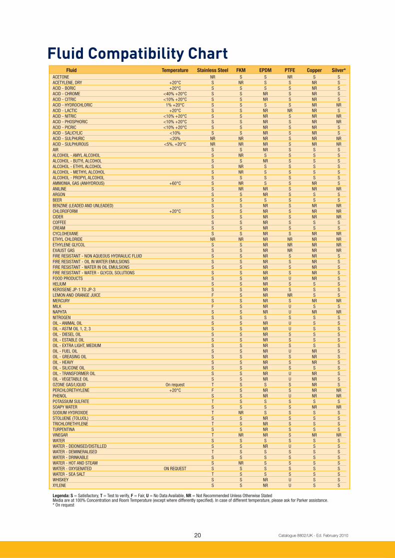
Fluid Compatibility Chart Fluid Temperature Stainless Steel FKM EPDM PTFE Copper Silver*
ACETONE NR S S NR S S
ACETYLENE, DRY +20°C S NR S S NR S
ACID - BORIC +20°C S S S S NR S
ACID - CHROME <40% +20°C S S NR S NR S
ACID - CITRIC <10% +20°C S S NR S NR S
ACID - HYDROCHLORIC 1% +20°C S S S S NR NR
ACID - LACTIC +20°C S S NR NR NR S
ACID - NITRIC <10% +20°C S S NR S NR NR
ACID - PHOSPHORIC <10% +20°C S S NR S NR NR
ACID - PICRIC <10% +20°C S S NR S NR S
ACID - SALICYLIC <10% S S NR S NR S
ACID - SULPHURIC <20% NR NR NR S NR NR
ACID - SULPHUROUS <5%, +20°C NR NR NR S NR NR
AIR S S NR S S S
ALCOHOL - AMYL ALCOHOL S NR S S S S
ALCOHOL - BUTYL ALCOHOL S S NR S S S
ALCOHOL - ETHYL ALCOHOL S NR S S S S
ALCOHOL - METHYL ALCOHOL S NR S S S S
ALCOHOL - PROPYL ALCOHOL S S S S S S
AMMONIA, GAS (ANHYDROUS) +60°C S NR S S NR S
ANILINE S NR NR S NR NR
ARGON S S NR S S S
BEER S S S S S S
BENZINE (LEADED AND UNLEADED) S S NR S NR NR
CHLOROFORM +20°C S S NR S NR NR
CIDER S S NR S NR NR
COFFEE S S NR S S S
CREAM S S NR S S S
CYCLOHEXANE S S NR S NR NR
ETHYL CHLORIDE NR NR NR NR NR NR
ETHYLENE GLYCOL S S NR NR NR NR
EXAUST GAS S S NR NR NR NR
FIRE RESISTANT - NON AQUEOUS HYDRAULIC FLUID S S NR S NR S
FIRE RESISTANT - OIL IN WATER EMULSIONS S S NR S NR S
FIRE RESISTANT - WATER IN OIL EMULSIONS S S NR S NR S
FIRE RESISTANT - WATER - GLYCOL SOLUTIONS S S NR S NR S
FOOD PRODUCTS S S NR U NR S
HELIUM S S NR S S S
KEROSENE JP-1 TO JP-3 S S NR S S S
LEMON AND ORANGE JUICE F S NR NR S S
MERCURY S S NR S NR NR
MILK F S NR U S S
NAPHTA S S NR U NR NR
NITROGEN S S S S S S
OIL - ANIMAL OIL S S NR U S S
OIL - ASTM OIL 1, 2, 3 S S NR U S S
OIL - DIESEL OIL S S NR S S S
OIL - ESTABLE OIL S S NR S S S
OIL - EXTRA LIGHT, MEDIUM S S NR S S S
OIL - FUEL OIL S S NR U NR S
OIL - GREASING OIL S S NR S NR S
OIL - HEAVY S S NR S NR S
OIL - SILICONE OIL S S NR S S S
OIL - TRANSFORMER OIL S S NR U NR S
OIL - VEGETABLE OIL S S NR U NR S
OZONE GAS/LIQUID On request T S S S NR S
PERCHLORETHYLENE +20°C F S NR S NR NR
PHENOL S S NR U NR NR
POTASSIUM SULFATE T S S S S S
SOAPY WATER S S S S NR NR
SODIUM HYDROXIDE T NR S S S S
STOLUENE (TOLUOL) S S NR S S S
TRICHLORETHYLENE T S NR S S S
TURPENTINA S S NR S S S
VINEGAR T NR NR S NR NR
WATER S S S S S S
WATER - DEIONISED/DISTILLED S S NR U S S
WATER - DEMINERALISED T S S S S S
WATER - DRINKABLE S S S S S S
WATER - HOT AND STEAM S NR S S S S
WATER - OXYGENATED ON REQUEST S S S S S S
WATER - SEA SALT T S S S S S
WHISKEY S S NR U S S
XYLENE S S NR U S S
Legenda: S = Satisfactory, T = Test to verify, F = Fair, U = No Data Available, NR = Not Recommended Unless Otherwise Stated Media are at 100% Concentration and Room Temperature (except where differently specifi ed). In case of different temperature, please ask for Parker assistance. * On request
21 Catalogue 8802/UK - Ed. February 2010
General Description
Valve Body:
AISI316L Stainless Steel
Enclosing tube:
AISI 303 Stainless Steel
Plunger: AISI 430F Stainless Steel
Spring:
AISI 302 Stainless Steel
Seals:
FKM
Shading ring:
Copper - Standard
Silver - optional (Consult Factory)
Material Specifi cations
Installation
The valves can be mounted in any position. It is however recommended to install them with the coil in
vertical position above the body.
Electrical Parts
A wide range of electrical parts can be used with this range.
The complete offer of electrical parts is described at pages 28-39.
Please consult also the "How to order" section at page 44 to select the product confi guration which fi ts your application
requirements.
Media
These valves have been developed to achieve the best performances with a wide range of media.
Please consult fl uid compatibility chart at page 20.

222222222222222 Catalogue 8802/UK - Ed. February 2010
Product Availability
201LG Series Pressure Vessel
This catalogue has been designed to make selection as easy as possible. The structure allows you to
fi nd your valve step by step, beginning with the most basic features and gradually focusing on more and
more precise details.
A wide range of confi gurations for this solenoid valve family is available: port sizes from 1/8" to ½" with
BSP port threads.
Please consult the following pages 23 to 27 to fi nd out our product solutions.
In the table herebelow you might also fi nd an explanation of the general description system for 201LG
family range.
Please note:
Electrical parts available are not included in the description system herebelow which refers to pressure vessel only.
Please consult in detail the "How to order" section at page 44.
2 0 1 L G 4 U V G 7
2 Number of Ways: 2, 3, 4, …
0 Design/Style: 0-Direct acting, 2-Dia phragm center pilot, 3-Diaphragm hung, …
1 Function: 1-Normally closed, 2-Normally open, 3-Universal, 4-Directional control
L Body Material: L = AISI316L machined body
G Port size: G1-1/8"G, G2-1/4"G, G3-3/8"G, G4-1/2"G
U Orifi ce size: G-from 1.42 to 1.6 mm, J-from 1.81 mm to 2.0 mm, L-from 2.25 mm
to 2.51 mm, N-from 2.83 to 3.16, P-from 3.17 to 3.55, S-from 4.51 mm
to 5.0 mm, U-from 5.63 mm to 6.31 mm.
V V-FKM, T-PTFE, E-EPDM
G Engineering design location: G-Gessate
7 Operator size: 7-14.5 sleeve diameter, 2-10.0 mm sleeve diameter

23 Catalogue 8802/UK - Ed. February 2010
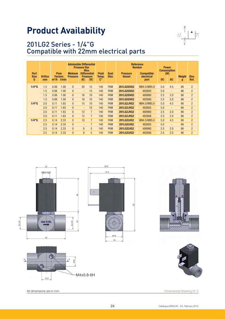
All dimensions are in mm
201LG1 Series - 1/8"G Compatible with 22mm Electrical parts
Dimensional Drawing N° 1
Admissible Differential Reference Pressure Bar Number Power Max. Consumption Port Flow Minimum Differential Fluid Seat Pressure Compatible (W) Size Orifi ce Factors Pressure Pressure Temp. Disc Vessel electrical Weight Dim. G mm m3/h l/min AC DC C° part DC AC g Ref.
1/8"G 1.5 0.06 1.00 0 20 15 140 FKM 201LG1GVG2 WB4.5/WB5.0 5.0 4.5 94 1
1.5 0.06 1.00 0 - 15 140 FKM 201LG1GVG2 482605 5.0 - 94 1
1.5 0.06 1.00 0 16 10 140 FKM 201LG1GVG2 488980 2.5 2.0 94 1
1.5 0.06 1.00 0 16 10 140 FKM 201LG1GVG2 482606 2.5 2.0 94 1
1/8"G 2.0 0.11 1.83 0 15 10 140 FKM 201LG1JVG2 WB4.5/WB5.0 5.0 4.5 94 1
2.0 0.11 1.83 0 - 10 140 FKM 201LG1JVG2 482605 5.0 - 94 1
2.0 0.11 1.83 0 12 7 140 FKM 201LG1JVG2 488980 2.5 2.0 94 1
2.0 0.11 1.83 0 12 7 140 FKM 201LG1JVG2 482606 2.5 2.0 94 1
1/8"G 2.5 0.14 2.33 0 10 7 140 FKM 201LG1LVG2 WB4.5/WB5.0 5.0 4.5 94 1
2.5 0.14 2.33 0 - 7 140 FKM 201LG1LVG2 482605 5.0 - 94 1
2.5 0.14 2.33 0 8 5 140 FKM 201LG1LVG2 488980 2.5 2.0 94 1
2.5 0.14 2.33 0 8 5 140 FKM 201LG1LVG2 482606 2.5 2.0 94 1
24 Catalogue 8802/UK - Ed. February 2010
All dimensions are in mm
201LG2 Series - 1/4"G Compatible with 22mm electrical parts
Dimensional Drawing N° 2
Admissible Differential Reference Pressure Bar Number Power Max. Consumption Port Flow Minimum Differential Fluid Seat Pressure Compatible (W) Size Orifi ce Factors Pressure Pressure Temp. Disc Vessel electrical Weight Dim. G mm m3/h l/min AC DC C° part DC AC g Ref.
1/4"G 1.5 0.06 1.00 0 20 15 140 FKM 201LG2GVG2 WB4.5/WB5.0 5.0 4.5 86 2
1.5 0.06 1.00 0 - 15 140 FKM 201LG2GVG2 482605 5.0 - 86 2
1.5 0.06 1.00 0 16 10 140 FKM 201LG2GVG2 488980 2.5 2.0 86 2
1.5 0.06 1.00 0 16 10 140 FKM 201LG2GVG2 482606 2.5 2.0 86 2
1/4"G 2.0 0.11 1.83 0 15 10 140 FKM 201LG2JVG2 WB4.5/WB5.0 5.0 4.5 86 2
2.0 0.11 1.83 0 - 10 140 FKM 201LG2JVG2 482605 5.0 - 86 2
2.0 0.11 1.83 0 12 7 140 FKM 201LG2JVG2 488980 2.5 2.0 86 2
2.0 0.11 1.83 0 12 7 140 FKM 201LG2JVG2 482606 2.5 2.0 86 2
1/4"G 2.5 0.14 2.33 0 10 7 140 FKM 201LG2LVG2 WB4.5/WB5.0 5.0 4.5 86 2
2.5 0.14 2.33 0 - 7 140 FKM 201LG2LVG2 482605 5.0 - 86 2
2.5 0.14 2.33 0 8 5 140 FKM 201LG2LVG2 488980 2.5 2.0 86 2
2.5 0.14 2.33 0 8 5 140 FKM 201LG2LVG2 482606 2.5 2.0 86 2
Product Availability

25 Catalogue 8802/UK - Ed. February 2010
All dimensions are in mm
201LG2 Series - 1/4"G Compatible with 32mm, 37mm and 40mm electrical parts
Dimensional Drawing N° 3
Admissible Differential Reference Pressure Bar Number Power Max. Consumption Port Flow Minimum Differential Fluid Seat Pressure Housing Compatible (W) Size Orifi ce Factors Pressure Pressure Temp. Disc Vessel electrical Weight Dim. G mm m3/h l/min AC DC C° part DC AC g Ref.
1/4"G 3.0 0.27 4.5 0 8 8.0 140 FKM 201LG2NVG7 - 481865 9 8 219 3
3.0 0.27 4.5 0 8 - 140 FKM 201LG2NVG7 - 483510 - 9 219 3
3.0 0.27 4.5 0 8 8.0 140 FKM 201LG2NVG7 - 496081 9 8 219 -
3.0 0.27 4.5 0 11 10.0 140 FKM 201LG2NVG7 - 491514 12 11 219 3
3.0 0.27 4.5 0 11 10.0 140 FKM 201LG2NVG7 - 496082 12 11 219 -
3.0 0.27 4.5 0 19 11.0 140 FKM 201LG2NVG7 - 492425 14 14 219 3
3.0 0.27 4.5 0 9 7.5 140 FKM 201LG2NVG7 4270. 4538 481000 8 8 219 -
3.0 0.27 4.5 0 19 - 140 FKM 201LG2NVG7 4270. 8520 481044 - 14 219 -
3.0 0.27 4.5 0 6 8.0 140 FKM 201LG2NVG7 - 495905 8 8 219 -
1/4"G 3.5 0.36 6.0 0 6 6.0 140 FKM 201LG2PVG7 - 481865 9 8 219 3
3.5 0.36 6.0 0 6 - 140 FKM 201LG2PVG7 - 483510 - 9 219 3
3.5 0.36 6.0 0 6 6.0 140 FKM 201LG2PVG7 - 496081 9 8 219 -
3.5 0.36 6.0 0 8 7.0 140 FKM 201LG2PVG7 - 491514 12 11 219 3
3.5 0.36 6.0 0 8 7.0 140 FKM 201LG2PVG7 - 496082 12 11 219 -
3.5 0.36 6.0 0 14 6.0 140 FKM 201LG2PVG7 - 492425 14 14 219 3
3.5 0.36 6.0 0 6 5.5 140 FKM 201LG2PVG7 4270. 4538 481000 8 8 219 -
3.5 0.36 6.0 0 14 - 140 FKM 201LG2PVG7 4270. 8520 481044 - 14 219 -
3.5 0.36 6.0 0 6 6.0 140 FKM 201LG2PVG7 - 495905 8 8 219 -

26 Catalogue 8802/UK - Ed. February 2010
All dimensions are in mm
201LG3 Series - 3/8"G Compatible with 32mm, 37mm and 40mm electrical parts
Dimensional Drawing N° 4
Product Availability
Admissible Differential Reference Pressure Bar Number Power Max. Consumption Port Flow Minimum Differential Fluid Seat Pressure Housing Compatible (W) Size Orifi ce Factors Pressure Pressure Temp. Disc Vessel electrical Weight Dim. G mm m3/h l/min AC DC C° part DC AC g Ref.
3/8"G 5.0 0.66 11 0 3.0 3.0 140 FKM 201LG3SVG7 - 481865 9 8 201 4
5.0 0.66 11 0 3.0 - 140 FKM 201LG3SVG7 - 483510 - 9 201 4
5.0 0.66 11 0 3.0 3.0 140 FKM 201LG3SVG7 - 496081 9 8 201 -
5.0 0.66 11 0 4.0 4.0 140 FKM 201LG3SVG7 - 491514 12 11 201 4
5.0 0.66 11 0 4.0 4.0 140 FKM 201LG3SVG7 - 496082 12 11 201 -
5.0 0.66 11 0 7.0 3.5 140 FKM 201LG3SVG7 - 492425 14 14 201 4
5.0 0.66 11 0 3.0 2.5 140 FKM 201LG3SVG7 4270. 4538 481000 8 8 201 -
5.0 0.66 11 0 7.0 - 140 FKM 201LG3SVG7 4270. 8520 481044 - 14 201 -
5.0 0.66 11 0 2.0 3.0 140 FKM 201LG3SVG7 - 495905 8 8 201 -
3/8"G 6.2 0.78 13 0 2.0 2.0 140 FKM 201LG3UVG7 - 481865 9 8 201 4
6.2 0.78 13 0 2.0 - 140 FKM 201LG3UVG7 - 483510 - 9 201 4
6.2 0.78 13 0 2.0 2.0 140 FKM 201LG3UVG7 - 496081 9 8 201 -
6.2 0.78 13 0 3.0 2.0 140 FKM 201LG3UVG7 - 491514 12 11 201 4
6.2 0.78 13 0 3.0 2.0 140 FKM 201LG3UVG7 - 496082 12 11 201 -
6.2 0.78 13 0 4.5 2.5 140 FKM 201LG3UVG7 - 492425 14 14 201 4
6.2 0.78 13 0 2.5 1.5 140 FKM 201LG3UVG7 4270. 4538 481000 8 8 201 -
6.2 0.78 13 0 4.5 - 140 FKM 201LG3UVG7 4270. 8520 481044 - 14 201 -
6.2 0.78 13 0 2.0 2.0 140 FKM 201LG3UVG7 - 495905 8 8 201 -

27 Catalogue 8802/UK - Ed. February 2010
All dimensions are in mm
201LG4 Series - 1/2"G Compatible with 32mm, 37mm and 40mm electrical parts
Dimensional Drawing N° 5
Admissible Differential Reference Pressure Bar Number Power Max. Consumption Port Flow Minimum Differential Fluid Seat Pressure Housing Compatible (W) Size Orifi ce Factors Pressure Pressure Temp. Disc Vessel electrical Weight Dim. G mm m3/h l/min AC DC C° part DC AC g Ref.
1/2"G 5.0 0.66 11 0 2.0 3.0 140 FKM 201LG4SVG7 - 481865 9 8 177 5
5.0 0.66 11 0 2.0 - 140 FKM 201LG4SVG7 - 483510 - 9 177 5
5.0 0.66 11 0 2.0 3.0 140 FKM 201LG4SVG7 - 496081 9 8 177 -
5.0 0.66 11 0 3.0 4.0 140 FKM 201LG4SVG7 - 491514 12 11 177 5
5.0 0.66 11 0 3.0 4.0 140 FKM 201LG4SVG7 - 496082 12 11 177 -
5.0 0.66 11 0 7.0 3.5 140 FKM 201LG4SVG7 - 492425 14 14 177 5
5.0 0.66 11 0 3.0 2.5 140 FKM 201LG4SVG7 4270. 4538 481000 8 8 177 -
5.0 0.66 11 0 7.0 - 140 FKM 201LG4SVG7 4270. 8520 481044 - 14 177 -
5.0 0.66 11 0 3.0 3.0 140 FKM 201LG4SVG7 - 495905 8 8 177 -
1/2"G 6.2 0.78 13 0 2.0 2.0 140 FKM 201LG4UVG7 - 481865 9 8 177 5
6.2 0.78 13 0 2.0 - 140 FKM 201LG4UVG7 - 483510 - 9 177 -
6.2 0.78 13 0 2.0 2.0 140 FKM 201LG4UVG7 - 496081 9 8 177 5
6.2 0.78 13 0 3.0 2.0 140 FKM 201LG4UVG7 - 491514 12 11 177 5
6.2 0.78 13 0 3.0 2.0 140 FKM 201LG4UVG7 - 496082 12 11 177 -
6.2 0.78 13 0 4.5 2.5 140 FKM 201LG4UVG7 - 492425 14 14 177 5
6.2 0.78 13 0 2.5 1.5 140 FKM 201LG4UVG7 4270. 4538 481000 8 8 177 -
6.2 0.78 13 0 4.5 - 140 FKM 201LG4UVG7 4270. 8520 481044 - 14 177 -
6.2 0.78 13 0 2.0 2.0 140 FKM 201LG4UVG7 - 495905 8 8 177 -

28 Catalogue 8802/UK - Ed. February 2010
All dimensions are in mm
22 mm Electrical Parts
Dimensional Drawing N° 6
Electrical Parts Availability
WB Series - Standard Coil Bi-Frequency and UL approved, F Class, IP65
Coil manufactured with H Class copper wire, moulded in thermoplastic material polyester with 30% glass
fi bre. IP65 protection rate with DIN 43650B three pin connector.
This coil conforms to the IEC/CENELEC safety standards and complies with European low-voltage
directive 73/23/EC.
VoltageTolerances: -10% to +10% of the nominal voltage (AC), -5% to +10% of the nominal voltage (DC)
Duty: Continuous duty coil (100%ED)
Weight: 100 g with plug
Voltage Power Reference Approvals Ambient Class Dimensional
Consumption Temperature of insulation Drawing
115/50-60 4.5 W WB 4.5 115/50-60 - -10°C to +50°C F Class 155°C 6
230/50-60 4.5 W WB 4.5 230/50-60 - -10°C to +50°C F Class 155°C 6
24/50-60 4.5 W WB 4.5 24/50-60 - -10°C to +50°C F Class 155°C 6
240/50-60 4.5 W WB 4.5 240/50-60 - -10°C to +50°C F Class 155°C 6
42/50-60 4.5 W WB 4.5 42/50-60 - -10°C to +50°C F Class 155°C 6
48/50-60 4.5 W WB 4.5 48/50-60 - -10°C to +50°C F Class 155°C 6
115/60 UR 4.5 W WB4.5 115/60 UR UL -10°C to +50°C F Class 155°C 6
208-240/60 UR 4.5 W WB4.5 208-240/60 UR UL -10°C to +50°C F Class 155°C 6
24/60 UR 4.5 W WB4.5 24/60 UR UL -10°C to +50°C F Class 155°C 6
110 DC 5 W WB 5.0 110 DC - -10°C to +50°C F Class 155°C 6
12 DC 5 W WB 5.0 12 DC - -10°C to +50°C F Class 155°C 6
24 DC 5 W WB 5.0 24 DC - -10°C to +50°C F Class 155°C 6
29 Catalogue 8802/UK - Ed. February 2010
All dimensions are in mm Dimensional Drawing N° 7
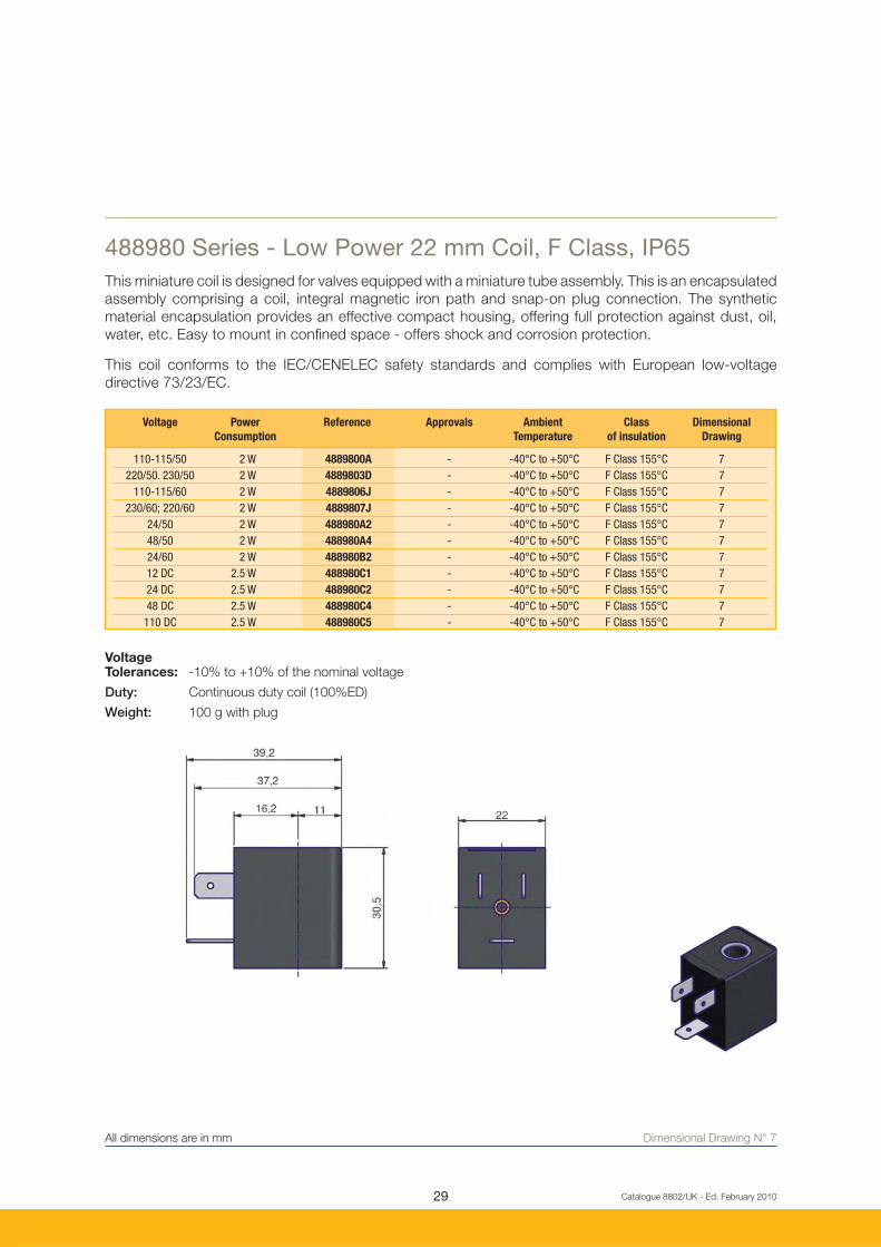
488980 Series - Low Power 22 mm Coil, F Class, IP65
This miniature coil is designed for valves equipped with a miniature tube assembly. This is an encapsulated
assembly comprising a coil, integral magnetic iron path and snap-on plug connection. The synthetic
material encapsulation provides an effective compact housing, offering full protection against dust, oil,
water, etc. Easy to mount in confi ned space - offers shock and corrosion protection.
This coil conforms to the IEC/CENELEC safety standards and complies with European low-voltage
directive 73/23/EC.
VoltageTolerances: -10% to +10% of the nominal voltage
Duty: Continuous duty coil (100%ED)
Weight: 100 g with plug
Voltage Power Reference Approvals Ambient Class Dimensional
Consumption Temperature of insulation Drawing
110-115/50 2 W 4889800A - -40°C to +50°C F Class 155°C 7
220/50. 230/50 2 W 4889803D - -40°C to +50°C F Class 155°C 7
110-115/60 2 W 4889806J - -40°C to +50°C F Class 155°C 7
230/60; 220/60 2 W 4889807J - -40°C to +50°C F Class 155°C 7
24/50 2 W 488980A2 - -40°C to +50°C F Class 155°C 7
48/50 2 W 488980A4 - -40°C to +50°C F Class 155°C 7
24/60 2 W 488980B2 - -40°C to +50°C F Class 155°C 7
12 DC 2.5 W 488980C1 - -40°C to +50°C F Class 155°C 7
24 DC 2.5 W 488980C2 - -40°C to +50°C F Class 155°C 7
48 DC 2.5 W 488980C4 - -40°C to +50°C F Class 155°C 7
110 DC 2.5 W 488980C5 - -40°C to +50°C F Class 155°C 7

30 Catalogue 8802/UK - Ed. February 2010
22 mm Explosion Proof Electrical PartsEncapsulated electrical parts "m"
Dimensional Drawing N° 7
Electrical Parts Availability
Application: Control of solenoid valves in dangerous areas where explosion proof protection EEx m
II T4 or T5 is required.
Benefi ts: Coil and magnetic circuit encapsulated in synthetic material - offering shock and corrosion
protection. AC coils with integrated thermal fuse. Small size for ease of mounting in confi ned
spaces.
These electrical parts conform to the IEC/CENELEC safety standards and comply with European explosive
atmosphere directive 94/9/EC "ATEX"
VoltageTolerances: -10% to +10% of the nominal voltage
Duty: Continuous duty coil (100%ED)
Weight: 150 g with plug
Voltage Power Reference Approvals Type of Protection Ambient Class of Dim.
Consumption Gas Dust Temperature insulation Drawing
24V DC 5 W 482605C2 LCIE 02 ATEX 6014 X II 2 G - Eex m II T4 II 2 D - 130°C -40°C to +50°C F Class 155°C -
110- 115/50 2 W 4826060A* LCIE 02 ATEX 6014 X II 2 G - Eex m II T5 II 2 D - 95°C -40°C to +50°C F Class 155°C 7
220/50, 230/50 2 W 4826063D* LCIE 02 ATEX 6014 X II 2 G - Eex m II T5 II 2 D - 95°C -40°C to +50°C F Class 155°C 7
24/50 2 W 482606A2* LCIE 02 ATEX 6014 X II 2 G - Eex m II T5 II 2 D - 95°C -40°C to +50°C F Class 155°C 7
24 DC 2.5 W 482606C2* LCIE 02 ATEX 6014 X II 2 G - Eex m II T5 II 2 D - 95°C -40°C to +50°C F Class 155°C 7
* with 1.5 m CABLE and DIN PLUG, IP65
All dimensions are in mm

31
18.8
37,5
20
32
24
35.5 19.5
Catalogue 8802/UK - Ed. February 2010
32 mm Electrical Parts Availability
Dimensional Drawing N° 8
481865 Series - Standard Coil Mono-Frequency, F Class, IP65
Encapsulated in synthetic material, Connector for 2P+E DIN 43650 A Plug, IP65 insulation class to be
considered with connector plug only. This coil conforms to the IEC/CENELEC safety standards and
complies with European low-voltage directive 73/23/EC.
This coil conforms to the IEC/CENELEC safety standards and complies with European low-voltage
directive 73/23/EC.
VoltageTolerances: -10% to +10% of the nominal voltage (AC), -5% to +10% of the nominal voltage (DC)
Duty: Continuous duty coil (100%ED)
Weight: 130 g (without plug)
Voltage Power Reference Approvals Ambient Class Dimensional
Consumption Temperature of insulation Drawing
24/50 8 W 481865A2 - -40°C to +50°C F Class 155°C 8
48/50 8 W 481865A4 - -40°C to +50°C F Class 155°C 8
110/50 8 W 481865A5 - -40°C to +50°C F Class 155°C 8
220-230/50 8 W 4818653D - -40°C to +50°C F Class 155°C 8
380/50 8 W 481865A9 - -40°C to +50°C F Class 155°C 8
24/60 8 W 481865B2 - -40°C to +50°C F Class 155°C 8
230/60 8 W 481865J3 - -40°C to +50°C F Class 155°C 8
115/60 8 W 481865K8 - -40°C to +50°C F Class 155°C 8
12 DC 9 W 481865C1 - -40°C to +50°C F Class 155°C 8
24 DC 9 W 481865C2 - -40°C to +50°C F Class 155°C 8
48 DC 9 W 481865C4 - -40°C to +50°C F Class 155°C 8
110V DC 9 W 481865C5 - -40°C to +50°C F Class 155°C 8
All dimensions are in mm

32
18.8
37,5
20
32
24
35.5 19.5
Catalogue 8802/UK - Ed. February 2010
32 mm Electrical Parts Availability
Dimensional Drawing N° 8
483510 Series - Standard Bi-Frequency Coil, F Class, IP65
Encapsulated in synthetic material, Connector for 2P+E DIN 43650 A Plug, IP65 insulation class to be
considered with connector plug only.
This coil conforms to the IEC/CENELEC safety standards and complies with European low-voltage
directive 73/23/EC.
VoltageTolerances: -10% to +10% of the nominal voltage (AC), -5% to +10% of the nominal voltage (DC)
Duty Continuous duty coil (100%ED)
Weight: 130 g (without plug)
Electrical Parts Availability
All dimensions are in mm
Voltage Power Reference Approvals Ambient Class Dimensional
Consumption Temperature of insulation Drawing
12/50-60 9 W 4835101W - -40°C to +50°C F Class 155°C 8
24/50-60 9 W 483510P0 - -40°C to +50°C F Class 155°C 8
48/50-60 9 W 483510S4 - -40°C to +50°C F Class 155°C 8
110-115/50 120/60 9 W 483510S5 - -40°C to +50°C F Class 155°C 8
220-240/50 240/60 9 W 483510S6 - -40°C to +50°C F Class 155°C 8
33
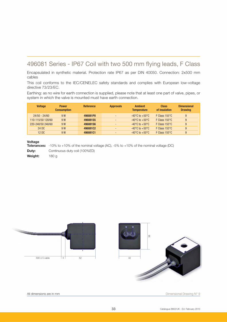
52 325500 ± 5 cable
38
Catalogue 8802/UK - Ed. February 2010
Dimensional Drawing N° 9
496081 Series - IP67 Coil with two 500 mm fl ying leads, F Class
Encapsulated in synthetic material. Protection rate IP67 as per DIN 40050. Connection: 2x500 mm
cables
This coil conforms to the IEC/CENELEC safety standards and complies with European low-voltage
directive 73/23/EC.
Earthing: as no wire for earth connection is supplied, please note that at least one part of valve, pipes, or
system in which the valve is mounted must have earth connection.
VoltageTolerances: -10% to +10% of the nominal voltage (AC), -5% to +10% of the nominal voltage (DC)
Duty: Continuous duty coil (100%ED)
Weight: 180 g
All dimensions are in mm
Voltage Power Reference Approvals Ambient Class Dimensional
Consumption Temperature of insulation Drawing
24/50 - 24/60 9 W 496081P0 - -40°C to +50°C F Class 155°C 9
110-115/50 120/60 9 W 496081S5 - -40°C to +50°C F Class 155°C 9
220-240/50 240/60 9 W 496081S6 - -40°C to +50°C F Class 155°C 9
24 DC 9 W 496081C2 - -40°C to +50°C F Class 155°C 9
12 DC 9 W 496081C1 - -40°C to +50°C F Class 155°C 9

34
18.8
37,5
20
32
24
35.5 19.5
Catalogue 8802/UK - Ed. February 2010
32 mm Electrical Parts Availability
Dimensional Drawing N° 8
491514 Series - 32 mm UL - Recognized Coil
This is an encapsulated assembly comprising a coil, integral magnetic-iron path and snap-on plug
connection. The synthetic material encapsulated provides an effective compact housing, offering full
protection against dust, oil, water, etc. Ease of mounting in confi ned space - offers shock and corrosion
protection.
This coil is UL-approved as a recognized component for the insulation Class F, conforms to the IEC/
CENELEC safety standards and complies with European low-voltage directive 73/23/EC.
Specifi cation: UL recognized coil - UL fi le E125678
Voltage Power Reference Approvals Ambient Class Dimensional
Consumption Temperature of insulation Drawing
24/60 13 W 491514B2 UL -40°C to +50°C F Class 155°C 8
24DC 16 W 491514C2 UL/VDE -40°C to +50°C F Class 155°C 8
110/50 120/60 13 W 491514P3 UL -40°C to +50°C F Class 155°C 8
220/50 240/60 13 W 491514Q3 UL -40°C to +50°C F Class 155°C 8
Electrical Parts Availability
All dimensions are in mm

35
52 325500 ± 5 cable
38
Catalogue 8802/UK - Ed. February 2010
Dimensional Drawing N° 9
496082 Series- IP67 Coil with two 500mm fl ying leads, F Class
Encapsulated in synthetic material. Protection rate IP67 as per DIN 40050. Connection: 2x500mm cables.
This coil conforms to the IEC/CENELEC safety standards and complies with European low-voltage directive
73/23/EC.
Earthing: as no wire for earth connection is supplied, please note that at least one part of valve, pipes, or
system in which the valve is mounted must have earth connection.
This coil is UL-approved as a recognized component for the insulation Class F, conforms to the IEC/CENELEC
safety standards and complies with European low-voltage directive 73/23/EC.
Specifi cation: UL recognized coil - UL fi le E125678
Voltage Tolerances: -10% to +10% of the nominal voltage (AC), -5% to +10% of the nominal voltage (DC)
Duty: Continuous duty coil (100%ED)
Weight: 180 g
Voltage Power Reference Approvals Ambient Class Dimensional
Consumption Temperature of insulation Drawing
24/60 13 W 496082B2 UL -40°C to +50°C F Class 155°C 9
110/50 120/60 13 W 496082P3 UL -40°C to +50°C F Class 155°C 9
208-240/60 13 W 496082U3 UL -40°C to +50°C F Class 155°C 9
220/50 240/60 14 W 496082Q3 UL -40°C to +50°C F Class 155°C 9
24 DC 16 W 496082C2 UL -40°C to +50°C F Class 155°C 9
12 DC 16 W 496082C1 UL - - 9
All dimensions are in mm

36 Catalogue 8802/UK - Ed. February 2010
32 mm Electrical Parts Availability
Dimensional Drawing N° 10
492425 Series - High Temperature/High Power H Class, IP65
Encapsulated in synthetic material, Connector for 2P + E DIN 43650 A Plug, IP65 insulation class to be
considered with connector plug only.
This coil conforms to the IEC/CENELEC safety standards and complies with European low-voltage
directive 73/23/EC.
Voltage Tolerances: -10% to +10% of the nominal voltage (AC), -5% to +10% of the nominal voltage (DC)
Duty: Continuous duty coil (100%ED)
Weight: 130 g (without plug)
Voltage Power Reference Approvals Ambient Class Dimensional
Consumption Temperature of insulation Drawing
24/50 14 W 492425A2 - -40°C to +80°C H Class 180°C 10
110/50 14 W 492425A5 - -40°C to +80°C H Class 180°C 10
230/50 14 W 492425F4 - -40°C to +80°C H Class 180°C 10
24 DC 14 W 492425C2 - -40°C to +80°C H Class 180°C 10
Electrical Parts Availability
All dimensions are in mm

37 Catalogue 8802/UK - Ed. February 2010
Dimensional Drawing N° 11
481000 Series - Standard F Class Coil with screw terminals
The coil winding is completely encapsulated in synthetic material. Electrical connection with screw terminals
for wire up to 1.5 mm.
This coil conforms to the IEC/CENELEC safety standards and complies with European low-voltage directive
73/23/EC. This coil must be used with a metallic housing.
Please consult page 40-42 to identify non-standard metallic housings availability.
Voltage Tolerances: -10% to +10% of the nominal voltage
Duty: Continuous duty coil (100%ED)
Weight: 130 g (without plug)
Voltage Power Reference Approvals Ambient Class Dimensional
Consumption Temperature of insulation Drawing
110-115/50 8 W 4810000A - -40°C to +50°C F Class 155°C 11
220/50, 230/50 8 W 4810003D - -40°C to +50°C F Class 155°C 11
240/60; 220/60 8 W 4810004K - -40°C to +50°C F Class 155°C 11
380/50; 440/60 8 W 4810005P - -40°C to +50°C F Class 155°C 11
110-115/60 8 W 4810006J - -40°C to +50°C F Class 155°C 11
24/50 8 W 481000A2 - -40°C to +50°C F Class 155°C 11
48/50 8 W 481000A4 - -40°C to +50°C F Class 155°C 11
24/60 8 W 481000B2 - -40°C to +50°C F Class 155°C 11
12 DC 8 W 481000C1 - -40°C to +50°C F Class 155°C 11
24 DC 8 W 481000C2 - -40°C to +50°C F Class 155°C 11
48 DC 8 W 481000C4 - -40°C to +50°C F Class 155°C 11
110 DC 8 W 481000C5 - -40°C to +50°C F Class 155°C 11
42/50; 48/60 8 W 481000S7 - -40°C to +50°C F Class 155°C 11
All dimensions are in mm
40mm Electricl Parts Availability

38 Catalogue 8802/UK - Ed. February 2010
40 mm Electrical Parts Availability
481044 Series - High Power Coil with screw terminals
The coil winding is completely encapsulated in synthetic material. Electrical connection with screw
terminals for wire up to 1.5 mm.
This coil conforms to the IEC/CENELEC safety standards and complies with European low-voltage
directive 73/23/EC.
This coil must be used with a metallic housing.
Please consult page 40-42 to identify non-standard metallic housings availability.
Voltage Tolerances: -10% to +10% of the nominal voltage)
Duty: Continuous duty coil (100%ED)
Weight: 130 g (without plug)
Voltage Power Reference Approvals Ambient Class Dimensional
Consumption Temperature of insulation Drawing
115/60; 100/50 14 W 4810440P - -40°C to +50°C H Class 155°C 12
24/50 14 W 481044A2 - -40°C to +50°C H Class 155°C 12
110/50 14 W 481044A5 - -40°C to +50°C H Class 155°C 12
220/50 14 W 481044A7 - -40°C to +50°C H Class 155°C 12
230/50 14 W 481044F4 - -40°C to +50°C H Class 155°C 12
230/60; 200/50 14 W 481044S2 - -40°C to +50°C H Class 155°C 12
Electrical Parts Availability
Dimensional Drawing N° 12All dimensions are in mm

39
15
27
60
37
38
51.4
26.5 104
135
96.5
Catalogue 8802/UK - Ed. February 2010
37mm Electrical Parts Availability
Dimensional Drawing N° 13
495905 Series - Explosion-Proof II 2 G-EEx dm IIC T4
Coil/housing assembly encapsulated in synthetic material (H class). Protection degree: IP67. Cable connection
through cable gland M20x1.5 (DIN 46320).
Voltage Power Reference Approvals Type of Protection Ambient Class of Dim.
Consumption Gas Dust Temperature insulation Drawing
24 DC 8 W 495905C2 LCIE02 ATEX 6451 X II 2 G -Eex dm IIC T4 II 2D - +130°C -40 to +65 °C - 13
48 DC 8 W 495905C4 LCIE02 ATEX 6451 X II 2 G -Eex dm IIC T4 II 2D - +130°C -40 to +65 °C - 13
110 DC 8 W 495905C5 LCIE02 ATEX 6451 X II 2 G -Eex dm IIC T4 II 2D - +130°C -40 to +65 °C - 13
24/50 8 W 495905A2 LCIE02 ATEX 6451 X II 2 G -Eex dm IIC T4 II 2D - +130°C -40 to +65 °C - 13
48/50 8 W 495905A4 LCIE02 ATEX 6451 X II 2 G -Eex dm IIC T4 II 2D - +130°C -40 to +65 °C - 13
240/60 8 W 495905B8 LCIE02 ATEX 6451 X II 2 G -Eex dm IIC T4 II 2D - +130°C -40 to +65 °C - 13
115/50 8 W 495905E5 LCIE02 ATEX 6451 X II 2 G -Eex dm IIC T4 II 2D - +130°C -40 to +65 °C - 13
230/50 8 W 495905F4 LCIE02 ATEX 6451 X II 2 G -Eex dm IIC T4 II 2D - +130°C -40 to +65 °C - 13
115/60 8 W 495905K8 LCIE02 ATEX 6451 X II 2 G -Eex dm IIC T4 II 2D - +130°C -40 to +65 °C - 13
All dimensions are in mm

40 Catalogue 8802/UK - Ed. February 2010
For 481000 and 481044 Series Electrical Parts with screw terminals
4270 Series Standard Housing
This metal housing offers the ideal protection against shocks and corrosion - rotable 360°.
This housing can be used with 481000 and 481044 series electrical parts.
Material: Epoxy-coated steel
Degree ofProtection: IP according to IEC/EN60529
IP10 with armoured conduit
IP44 with cable gland
ElectricalConnection: Can be made with armoured conduit or cable gland M12x1.5,
Part N° 495740 and N°495741 to be ordered separately.
Grounding connection by screw M3 on the inside of the housing base plate.
Dimensions: See dimensional "Drawing N°14"
Weight: 120 g
Non-Standard Housings
Dimensional Drawing N° 14All dimensions are in mm

41 Catalogue 8802/UK - Ed. February 2010
4538 Series Waterproof and Dustproof Housing
This enclosure is dust and waterproof. It corresponds to the degree of "international protection" IP67
according to IEC/EN60529. Corrosion resistant, the metal housing offers good protection for the coil
against shocks. This housing must be equipped with 481000 Series electrical parts.
Material: Galvanized passivated steel
Degree ofProtection: IP67 according to IEC/EN 60529
ElectricalConnection: Cable connection by cable gland according to DIN46320.
Cable with outer diameter 6.5-13.5mm (M20x1.5) can be simply
sealed using a rubber gland resilient sealing rings.
The enclosure is internally and externally fi tted with grounding
and earthing screw terminals.
Dimensions: See dimensional "Drawing N°15"
Weight: 180 g
Dimensional Drawing N° 15All dimensions are in mm

42 Catalogue 8802/UK - Ed. February 2010
For 481000 and 481044 Series Electrical Parts with screw terminals
8720 Series Waterproof and Dustproof Housing
This enclosure is dust and waterproof. It corresponds to the degree of "international protection" IP67
according to IEC/EN60529. Corrosion resistant, the metal housing offers good protection for the coil
against shocks. This housing must be equipped with 481044 Series electrical parts.
Material: Galvanized passivated steell
Degree ofProtection: IP67 according to IEC/EN 60529
ElectricalConnection: Cable connection by cable gland according to DIN46320.
Cable with outer diameter 6.5-13.5mm (M20x1.5) can be simply
sealed using a rubber gland resilient sealing rings.
The enclosure is internally and externally fi tted with grounding
and earthing screw terminals.
Dimensions: See dimensional "Drawing N°16"
Weight: 180 g
Dimensional Drawing N° 16All dimensions are in mm

43 Catalogue 8802/UK - Ed. February 2010
Connectors
Dimensional Drawing N° 18All dimensions are in mm
Dimensional Drawing N° 17All dimensions are in mm
2P + E DIN 43650A Plug
2P + E DIN 43650A Plug
Maximum Cable Nominal Reference Dimensional
A Section Voltage Drawing
16 A 6-10 mm2 250-/300V= 600040 18
Maximum Cable Nominal Reference Dimensional
A Section Voltage Drawing
16 A 6-10 mm2 250-/300V= 600003 PLUG 17

44 Catalogue 8802/UK - Ed. February 2010
How to Order
Step 1
Select the pressure vessel reference needed at pages 23 to 27.
Step 2
Select coil at pages 28 to 39.
Step 4
Select accessories at page 44.
Step 3
For 481000 and 481044 electrical parts only.
Please select the non-standard housing reference you need at pages 40 to 42.
A complete solenoid valve is composed by 3 elements: the Pressure Vessel, the Housing and the Coil.
201LG Series pressure vessel is supplied with the standard housing integrated. Standard housing is
composed by washer and nut for 22 mm range, and washer, nut and nameplate for 32 mm range.
Pressure vessel, electrical parts, non-standard housings and accessories must be ordered
separately.
Ordering a product or a confi guration not listed in the catalogue
When an application demands a combination of features not listed in the catalogue, use the signifi cant description system indicated
at page 17 to specify the exact valve needed. Parker FCDE personnel will assist in determining the applicability, availability and price
of the new product.

45 Catalogue 8802/UK - Ed. February 2010
Notes

46 Catalogue 8802/UK - Ed. February 2010
WARNING - USER RESPONSIBILITY
FAILURE OR IMPROPER SELECTION OR IMPROPER USE OF THE PRODUCTS DESCRIBED HEREIN OR RELATED ITEMS CAN CAUSE DEATH,
PERSONAL INJURY AND PROPERTY DAMAGE.
• This document and other information from Parker-Hannifi n Corporation, its subsidiaries and authorized distributors provide product or system options for further
investigation by users having technical expertise.
• The user, through its own analysis and testing, is solely responsible for making the fi nal selection of the system and components and assuring that all performance,
endurance, maintenance, safety and warning requirements of the application are met. The user must analyze all aspects of the application, follow applicable industry
standards, and follow the information concerning the product in the current product catalog and in any other materials provided from Parker or its subsidiaries or
authorized distributors.
• To the extent that Parker or its subsidiaries or authorized distributors provide component or system options based upon data or specifi cations provided by the
user, the user is responsible for determining that such data and specifi cations are suitable and suffi cient for all applications and reasonably foreseeable uses of the
components or systems.
Notes

AEROSPACE
Key Markets• Aircraft engines• Business & general aviation• Commercial transports• Land-based weapons systems• Military aircraft• Missiles & launch vehicles• Regional transports• Unmanned aerial vehicles
Key Products•• Flight control systems & components•• Fluid conveyance systems•• Fluid metering delivery & atomization devices•• Fuel systems & components•• Hydraulic systems & components•• Inert nitrogen generating systems•• Pneumatic systems & components• • Wheels & brakes
CLIMATE CONTROL
Key Markets•• Agriculture•• Air conditioning•• Food, beverage & dairy• Life sciences & medical•• Precision cooling•• Processing•• Transportation
Key Products•• CO2 controls•• Electronic controllers•• Filter driers•• Hand shut-off valves•• Hose & fi ttings•• Pressure regulating valves•• Refrigerant distributors•• Safety relief valves•• Solenoid valves•• Thermostatic expansion valves
FILTRATION
Key Markets•• Food & beverage•• Industrial machinery•• Life sciences•• Marine•• Mobile equipment•• Oil & gas•• Power generation•• Process•• Transportation
Key Products•• Analytical gas generators•• Compressed air & gas fi lters•• Condition monitoring•• Engine air, fuel & oil fi ltration & systems•• Hydraulic, lubrication
& coolant fi lters•• Process, chemical, water & microfi ltration fi lters•• Nitrogen, hydrogen & zero air generators
ELECTROMECHANICAL
Key Markets•• Aerospace•• Factory automation•• Food & beverage•• Life science & medical•• Machine tools• • Packaging machinery• • Paper machinery• • Plastics machinery & converting• • Primary metals•• Semiconductor & electronics• • Textile•• Wire & cable
Key Products• • AC/DC drives & systems•• Electric actuators• Controllers• Controllers• Gantry robots• Gantry robots•• Gearheads•• Human machine interfaces•• Industrial PCs• • Inverters•• Linear motors, slides and stages•• Precision stages• • Stepper motors•• Servo motors, drives & controls•• Structural extrusions
PNEUMATICS
Key Markets• Aerospace• Conveyor & material handling• Factory automation• Food & beverage• Life science & medical• Machine tools• Packaging machinery• Transportation & automotive
Key Products•• Air preparation•• Compact cylinders•• Field bus valve systems•• Grippers•• Guided cylinders•• Manifolds•• Miniature fl uidics•• Pneumatic accessories•• Pneumatic actuators & grippers •• Pneumatic valves and controls•• Rodless cylinders•• Rotary actuators•• Tie rod cylinders•• Vacuum generators, cups & sensors
FLUID & GAS HANDLING
Key Markets•• Aerospace•• Agriculture•• Bulk chemical handling•• Construction machinery•• Food & beverage•• Fuel & gas delivery•• Industrial machinery•• Mobile•• Oil & gas•• Transportation•• Welding
Key Products•• Brass fi ttings & valves•• Diagnostic equipment •• Fluid conveyance systems•• Industrial hose•• PTFE & PFA hose, tubing
& plastic fi ttings•• Rubber & thermoplastic hose & couplings•• Tube fi ttings & adapters•• Quick disconnects
HYDRAULICS
Key Markets• Aerospace• Aerial lift• Agriculture• Construction machinery• Forestry• Industrial machinery• Mining• Oil & gas• Power generation & energy• Truck hydraulics
Key Products• Diagnostic equipment• Hydraulic cylinders & accumulators• Hydraulic motors & pumps• Hydraulic systems• Hydraulic valves & controls• Power take-offs • Rubber & thermoplastic hose & couplings• Tube fi ttings & adapters• Quick disconnects
PROCESS CONTROL
Key Markets•• Chemical & refi ning•• Food, beverage & dairy•• Medical & dental•• Microelectronics•• Oil & gas•• Power generation
Key Products•• Analytical sample conditioning products & systems•• Fluoropolymer chemical delivery fi ttings, valves & pumps•• High purity gas delivery fi ttings, valves & regulators•• Instrumentation fi ttings, valves & regulators•• Medium pressure fi ttings & valves•• Process control manifolds
SEALING & SHIELDING
Key Markets•• Aerospace•• Chemical processing•• Consumer•• Energy, oil & gas•• Fluid power•• General industrial•• Information technology•• Life sciences•• Military•• Semiconductor•• Telecommunications•• Transportation
Key Products•• Dynamic seals•• Elastomeric o-rings •• EMI shielding•• Extruded & precision-cut, fabricated elastomeric seals•• Homogeneous & inserted elastomeric shapes •• High temperature metal seals•• Metal & plastic retained composite seals•• Thermal management
Parker’s Motion & Control TechnologiesAt Parker, we’re guided
by a relentless drive to help
our customers become more
productive and achieve
higher levels of profi tability
by engineering the best
systems for their require-
ments. It means looking at
customer applications from
many angles to fi nd new
ways to create value.
Whatever the motion and
control technology need,
Parker has the experience,
breadth of product and global
reach to consistently deliver.
No company knows more
about motion and control
technology than Parker.
For further info call
00800 27 27 5374.

AE - UAE, DubaiTel: +971 4 [email protected]
AR - Argentina, Buenos AiresTel: +54 3327 44 4129
AT - Austria, Wiener NeustadtTel: +43 (0)2622 [email protected]
AT - Eastern Europe, Wiener NeustadtTel: +43 (0)2622 23501 [email protected]
AU - Australia, Castle HillTel: +61 (0)2-9634 7777
AZ - Azerbaijan, BakuTel: +994 50 2233 [email protected]
BE/LU - Belgium, NivellesTel: +32 (0)67 280 [email protected]
BR - Brazil, Cachoeirinha RSTel: +55 51 3470 9144
BY - Belarus, MinskTel: +375 17 209 [email protected]
CA - Canada, Milton, OntarioTel: +1 905 693 3000
CH - Switzerland, EtoyTel: +41 (0) 21 821 02 30 [email protected]
CL - Chile, SantiagoTel: +56 2 623 1216
CN - China, ShanghaiTel: +86 21 2899 5000
CZ - Czech Republic, KlecanyTel: +420 284 083 [email protected]
DE - Germany, KaarstTel: +49 (0)2131 4016 [email protected]
DK - Denmark, BallerupTel: +45 43 56 04 [email protected]
ES - Spain, MadridTel: +34 902 330 [email protected]
FI - Finland, VantaaTel: +358 (0)20 753 2500parker.fi [email protected]
FR - France, Contamine s/ArveTel: +33 (0)4 50 25 80 [email protected]
GR - Greece, AthensTel: +30 210 933 [email protected]
HK - Hong KongTel: +852 2428 8008
HU - Hungary, BudapestTel: +36 1 220 [email protected]
IE - Ireland, DublinTel: +353 (0)1 466 [email protected]
IN - India, MumbaiTel: +91 22 6513 7081-85
IT - Italy, Corsico (MI)Tel: +39 02 45 19 [email protected]
JP - Japan, TokyoTel: +(81) 3 6408 3901
KR - South Korea, SeoulTel: +82 2 559 0400
KZ - Kazakhstan, AlmatyTel: +7 7272 505 [email protected]
LV - Latvia, RigaTel: +371 6 745 [email protected]
MX - Mexico, ApodacaTel: +52 81 8156 6000
MY - Malaysia, Shah AlamTel: +60 3 7849 0800
NL - The Netherlands, OldenzaalTel: +31 (0)541 585 [email protected]
NO - Norway, SkiTel: +47 64 91 10 [email protected]
NZ - New Zealand, Mt WellingtonTel: +64 9 574 1744
PL - Poland, WarsawTel: +48 (0)22 573 24 [email protected]
PT - Portugal, Leca da PalmeiraTel: +351 22 999 [email protected]
RO - Romania, BucharestTel: +40 21 252 [email protected]
RU - Russia, MoscowTel: +7 495 [email protected]
SE - Sweden, SpångaTel: +46 (0)8 59 79 50 [email protected]
SG - SingaporeTel: +65 6887 6300
SK - Slovakia, Banská BystricaTel: +421 484 162 [email protected]
SL - Slovenia, Novo MestoTel: +386 7 337 [email protected]
TH - Thailand, BangkokTel: +662 717 8140
TR - Turkey, IstanbulTel: +90 216 [email protected]
TW - Taiwan, TaipeiTel: +886 2 2298 8987
UA - Ukraine, KievTel +380 44 494 [email protected]
UK - United Kingdom, WarwickTel: +44 (0)1926 317 [email protected]
US - USA, Cleveland Tel: +1 216 896 3000
VE - Venezuela, CaracasTel: +58 212 238 5422
ZA - South Africa,Kempton ParkTel: +27 (0)11 961 [email protected]
Parker Worldwide
European Product Information Centre
Free phone: 00 800 27 27 5374
(from AT, BE, CH, CZ, DE, DK, EE, ES, FI,
FR, IE, IL, IS, IT, LU, MT, NL, NO, PL, PT, RU,
SE, UK, ZA)
Ed
. F
eb
ruary
2010
Parker Hannifi n Ltd.
Tachbrook Park Drive
Tachbrook Park, Warwick CV34 6TU
United Kingdom
Tel.: +44 (0) 1926 317 878
Fax: +44 (0) 1926 317 855
www.parker.com
Catalogue 8802/UK
Your local authorized Parker distributor
© 2010 Parker Hannifi n Corporation.
All rights reserved.