Embed Size (px)
Citation preview


PARK Lighting Supply and Installation Specification
MP-13-PRC-SP-001 2
Contents
1. GENERAL ................................................................................................................................... 7
1.1 Description of Project ................................................................................................................ 7
1.2 Introduction ................................................................................................................................. 7
1.3 Preliminary ................................................................................................................................... 7
1.4 Preface ........................................................................................................................................ 7
1.5 Reference Documents .............................................................................................................. 8
1.6 Scope of Works ........................................................................................................................... 8
1.7 Programme ................................................................................................................................. 9
1.8 Information and Submissions required. ................................................................................... 9
1.9 Tender Submissions (Sub-contractors/Suppliers) .................................................................... 9
1.10 Post Tender Submissions .......................................................................................................... 10
1.10.1 Project initial submissions ....................................................................................................... 10
1.10.2 Project testing submissions .................................................................................................... 10
1.10.3 Project closeout submissions ................................................................................................. 11
1.10.4 Layout and System Drawings ............................................................................................... 11
1.10.5 Submission process ................................................................................................................. 11
1.11 Documents, information and communications .................................................................. 12
1.12 Submission and communication timeframes ....................................................................... 12
1.13 Work Plans and Co-ordination Meetings .............................................................................. 12
1.14 Commons Terms and Abbreviations ..................................................................................... 13
1.15 Codes and Standards for Compliance ................................................................................ 15
1.16 Contractor’s design responsibility .......................................................................................... 17
1.17 Preferred Suppliers ................................................................................................................... 18
1.18 Environmental and Noise Conditions .................................................................................... 18
1.18.1 Site Boundary Noise Limits ..................................................................................................... 18
1.18.2 Ambient Conditions ............................................................................................................... 18
1.18.3 Durability Requirements......................................................................................................... 19
1.19 Dissimilar Materials .................................................................................................................... 19
1.20 Surface treatments and Protective Coatings ...................................................................... 19
1.21 Painting and Durability ............................................................................................................ 21
1.21.1 Park Painting ........................................................................................................................... 22
1.22 Galvanising ............................................................................................................................... 22
1.23 Identification ............................................................................................................................. 22
1.23.1 General .................................................................................................................................... 22
1.23.2 Marking .................................................................................................................................... 22
1.23.3 Reticulated Services – General ............................................................................................ 23
1.24 Operating and Maintenance Manuals – General .............................................................. 23
1.24.1 General .................................................................................................................................... 23
1.24.2 Format ...................................................................................................................................... 24

PARK Lighting Supply and Installation Specification
MP-13-PRC-SP-001 3
1.24.3 Content .................................................................................................................................... 24
1.24.4 As Built Drawings ..................................................................................................................... 26
1.25 Construction Producer Statements and Certificates of Compliance .............................. 26
1.26 Seismic Performance ............................................................................................................... 26
1.26.1 Application .............................................................................................................................. 26
1.26.1.1 Park works ......................................................................................................................... 27
1.26.2 Design ...................................................................................................................................... 27
1.27 Alternate Designs ..................................................................................................................... 27
1.28 Site of the Works ....................................................................................................................... 28
1.29 Drawings .................................................................................................................................... 28
1.30 Approvals .................................................................................................................................. 28
2. SUPPLY OF EQUIPMENT AND MATERIALS ............................................................................... 29
2.1 Shipment .................................................................................................................................... 29
2.2 Materials .................................................................................................................................... 29
2.3 Packing Requirements ............................................................................................................. 30
2.4 Storage ...................................................................................................................................... 30
2.5 Identification and Documents ............................................................................................... 30
2.6 Spares ........................................................................................................................................ 30
2.7 Date Processing ........................................................................................................................ 31
2.8 Power Quality and Electromagnetic Interference .............................................................. 31
2.9 Construction Record Drawings – Equipment ....................................................................... 31
2.9.1 General .................................................................................................................................... 31
2.9.2 Submission ............................................................................................................................... 31
2.10 Training ....................................................................................................................................... 31
2.10.1 Training Plan ............................................................................................................................ 32
2.10.2 Training Equipment ................................................................................................................ 32
2.10.3 Training Manuals ..................................................................................................................... 32
3. ON SITE INSTALLATION ........................................................................................................... 33
3.1 Free Issued Equipment ............................................................................................................ 33
3.2 Contractor Supplied Documents ........................................................................................... 33
3.3 Material Substitution ................................................................................................................. 33
3.4 Coordination and Setting Out ................................................................................................ 33
3.5 Installation ................................................................................................................................. 34
3.6 Fire Stopping ............................................................................................................................. 34
3.7 Construction Record Drawings – On site Installations ......................................................... 35
3.7.1 General .................................................................................................................................... 35
4. INSPECTIONS, SNAGGING AND DEFECTS ............................................................................. 37
4.1 Inspection prior to closing up ................................................................................................. 37
4.2 Snagging ................................................................................................................................... 37
4.3 Defects....................................................................................................................................... 38

PARK Lighting Supply and Installation Specification
MP-13-PRC-SP-001 4
5. TECHNICAL ............................................................................................................................. 39
5.1 LV Power Distribution System .................................................................................................. 39
5.2 Design Parameters ................................................................................................................... 39
5.3 Permanent Lighting Design ..................................................................................................... 40
5.3.1 Maintenance Factors ............................................................................................................ 40
5.3.2 Lighting Control ...................................................................................................................... 40
5.3.3 Lamp Lumens .......................................................................................................................... 40
5.3.4 Quantities ................................................................................................................................ 40
5.4 Luminaire performance........................................................................................................... 40
5.4.1 Luminaire construction .......................................................................................................... 40
5.4.1.1 General ............................................................................................................................. 40
5.4.1.2 Temperature Rating ........................................................................................................ 41
5.4.1.3 Voltage Rating ................................................................................................................. 41
5.4.1.4 Ballasts ............................................................................................................................... 41
5.4.1.5 Igniters ............................................................................................................................... 41
5.4.1.6 Control Gear .................................................................................................................... 41
5.4.1.7 Lamp Protection .............................................................................................................. 42
5.4.1.8 Performance .................................................................................................................... 42
5.4.1.9 Independent Photometric testing ................................................................................ 42
5.4.1.10 CIDs ................................................................................................................................... 42
5.4.2 Luminaire performance ......................................................................................................... 42
5.5 Vibration .................................................................................................................................... 42
5.6 Cables and Wiring .................................................................................................................... 43
5.6.1 General .................................................................................................................................... 43
5.6.2 Cable Types ............................................................................................................................ 43
5.6.3 Termination of Conductors ................................................................................................... 44
5.6.3.1 Cable joints ...................................................................................................................... 44
5.6.3.2 Pole connection boxes................................................................................................... 44
5.6.4 Cable and Core Identification ............................................................................................. 44
5.6.5 Earth Bonding .......................................................................................................................... 45
5.6.6 Cable Penetrations ................................................................................................................ 45
5.6.7 Containment ........................................................................................................................... 45
5.6.7.1 General ............................................................................................................................. 45
5.6.7.2 Conduit ............................................................................................................................. 45
5.6.7.3 Segregation ...................................................................................................................... 46
5.6.7.4 Jointing.............................................................................................................................. 46
5.6.7.5 Glanding ........................................................................................................................... 46
5.7 Electrical Switchgear ............................................................................................................... 46
5.7.1 General .................................................................................................................................... 46
5.8 Works Included ......................................................................................................................... 46
5.9 Compliance with Electrical Codes and Standards ............................................................. 46

PARK Lighting Supply and Installation Specification
MP-13-PRC-SP-001 5
5.10 Particular Requirements .......................................................................................................... 47
5.10.1 Workmanship and Materials ................................................................................................. 47
5.10.2 Operational, Maintenance and Access Requirements ................................................... 47
5.10.3 Physical Construction ............................................................................................................. 48
5.10.4 Bus-Bars .................................................................................................................................... 48
5.10.5 Earth and Neutral Provisions ................................................................................................. 49
5.11 Wiring and Terminations .......................................................................................................... 49
5.12 Chart Holders & MCB Charts .................................................................................................. 49
5.13 Labelling and Mimics ............................................................................................................... 49
6. INSTALLATION ......................................................................................................................... 51
6.1 Appurtenances ........................................................................................................................ 51
6.2 Co-ordination ........................................................................................................................... 51
6.3 Instructions ................................................................................................................................. 51
6.4 Alignment .................................................................................................................................. 51
6.5 Wiring ......................................................................................................................................... 51
6.6 Clean-up: .................................................................................................................................. 51
6.7 Free Issued Equipment ............................................................................................................ 51
6.8 Contractor Supplied Documents ........................................................................................... 51
6.9 Pre- Manufacture Submissions – On Site Installation ........................................................... 52
6.9.1 Layout and System Drawings ............................................................................................... 52
6.9.2 Design Details .......................................................................................................................... 52
6.9.3 Procedure ................................................................................................................................ 52
6.10 Work Plans and Co-ordination Meetings .............................................................................. 52
6.11 Material Substitution ................................................................................................................. 53
6.12 Coordination and Setting Out ................................................................................................ 53
6.13 Installation ................................................................................................................................. 53
6.14 Construction Record Drawings – On site Installations ......................................................... 54
6.14.1 General .................................................................................................................................... 54
6.14.2 Submission ............................................................................................................................... 55
7. LIGHTING INSTALLATION TESTING .......................................................................................... 56
7.1 General ...................................................................................................................................... 56
7.2 Testing and Commissioning Manual ...................................................................................... 56
7.3 Pre-Testing Procedures ............................................................................................................ 56
7.4 Testing ........................................................................................................................................ 57
7.5 Witnessing .................................................................................................................................. 57
7.6 Grid Size ..................................................................................................................................... 57
APPENDIX A ................................................................................................................................... 58

PARK Lighting Supply and Installation Specification
MP-13-PRC-SP-001 6
Tables
Table 1 – Reference Drawings ........................................................................................................... 8
Table 2 – Reference Specifications ................................................................................................... 8
Table 3 – Post Tender Submission ..................................................................................................... 11
Table 4 – Common Terms ................................................................................................................. 13
Table 5 – Common Abbreviations ................................................................................................... 13
Table 6 – Current Standards ............................................................................................................. 15
Table 7 – Ambient Conditions .......................................................................................................... 18
Table 8 – Durability Requirements ................................................................................................... 19
Table 9 – O&M Format ...................................................................................................................... 24
Table 10 – O&M Content .................................................................................................................. 24
Table 11 - List of associated drawings ............................................................................................ 28
Table 12 – Maintenance Factor(s) .................................................................................................. 40

PARK Lighting Supply and Installation Specification
MP-13-PRC-SP-001 7
1. GENERAL
1.1 Description of Project
The Memorial Park Alliance (MPA) has been established between NZTA, and the Non-owner
Participants (NOPs) Joint-venture of Downer, HEB, Tonkin & Taylor and URS.
MPA, operating under an Alliance Agreement, is tasked with the National Memorial Park
Underpass and Basin Reserve Bridge, along with enhancements to the adjacent Inner City
Bypass.
The construction of these assets will enable the creation of the National Memorial Park and
significantly improve traffic flows in the Basin Reserve area.
This specification outlines the Park lighting design and should be read in conjunction with
the Urban Design documentation is ensure the full understanding of the design philosophy.
1.2 Introduction
Where required, all consents shall be obtained and local authority fees paid for the
completion of all systems. Necessary time and costs shall be allowed for to fully comply with
ALL relevant Local Authority Body regulations, all relevant AS/NZS documents, Codes of
Practice and other relevant Acts, Regulations, Standards and Codes.
All parties (inclusive of Subcontractors and suppliers) shall comply with all Statutory, Local
Authority Fire Service and New Zealand Insurance Council requirements.
This specification relates specifically to project works in relation to the establishment of MEC
services for the Park for the Memorial Park Alliance Project.
1.3 Preliminary
This document outlines requirements for the design, manufacture, factory testing, delivery
to site, unloading, movement and placement in location, installation, site testing,
commissioning, witnessing, warranty and maintenance. The works described in this
specification and associated drawings shall form the basis of a design, supply, install and
commissioning contract.
The specification(s) and drawings identify the system concepts and standards of
performance and quality required, but do not purport to identify all problem areas and
their solution(s), which shall be the responsibility of the sub-contractor/supplier.
1.4 Preface
Electrical Services for the Park will be fed from a DB within the UAB building located near
the western end of the Park. The building will house all of the necessary electrical switch
gear to operate the electrical and mechanical equipment that will be utilised within the
Park.

PARK Lighting Supply and Installation Specification
MP-13-PRC-SP-001 8
1.5 Reference Documents
The following reference documents, drawings and specifications, shall be used for
coordination purposes.
Table 1 – Reference Drawings
Drawing Series Description
UND-13-000, 100 and
300 & 400 series
(excl. 13-070, 071 & 072)
Main Electrical Package
(includes Underpass Lighting, UAB security, plant communications and
controls as well as EEC/FCC cabinet security)
UND-13-500 series
ITS Field devices
(Includes field devices, racks & equipment at UAB, interconnecting
cabling)
Table 2 – Reference Specifications
Specification reference Description
MP-13-DES-SP-001 Main Electrical Supply and Installation Specification
MP-13-DES-SP-007 MEC General Technical Specification
1.6 Scope of Works
This specification is for the Park Lighting Supply and Installation. The contract includes the
supply, except where specifically stated otherwise, of all labour, materials, equipment,
tools, plant and scaffolding for the supply, delivery, installation, connection, testing,
commissioning, maintenance and guarantee of the complete installation which comprises
the following works (note, these works will be in conjunction with other works for the
Memorial Park Alliance):
The Park Lighting Contractor/Sub-contractor shall:
1. Supply and install all fittings and lamps to meet the requirements of the Park lighting
design specifications and drawings. (Refer to Appendix A - Schedule of fittings for details
of quantities and sizes of fittings.
2. Supply and installation of all poles for lighting purposes only.
3. Provide mounting brackets to mount all supplied fittings.
4. Comply with Environmental and Seismic design and installation.
5. Supply drawings and documentation for submission and installation
6. Deliver (including unloading) all supplied equipment to the designated lay down areas.
7. Provide spare parts.
8. Install the Park Lighting to the Principal’s and Park Lighting Sub-contractor’s
requirements.
9. Test and commission, providing test reports using calibrated equipment for the Park
Lighting to the Principal’s requirements in conjunction with the Park Lighting Sub-
contractor.
10. Provision of other such items to ensure a complete installation, this includes but is not
limited to lamps, luminaires, poles, cabling, control gear, fuse gear etc.
11. Liaise and coordinate with Wellington Electricity (Wellington City Council’s preferred
energy supplier and NZTA preferred energy supplier) to establish power supplies and
metering.

PARK Lighting Supply and Installation Specification
MP-13-PRC-SP-001 9
12. Coordination of civil work including trenching and backfill, thrusting and ducting,
conduits, penetrations ,excavation and foundations for lighting columns and
switchboards.
13. Earthing to AS/NZS3000 and Network supplier requirements.
14. Installation of LV distribution networks starting from the main incoming terminals of the
distribution boards and all related cables to the lighting poles.
15. Compiance with WCC and NZTA requirements.
16. Electrical safety testing by an IQP (Independently Qualified Person) and an electrical
Certificate of Compliance.
17. Preparation of construction and builders works drawings associated with the works
included in this specification including coordination with other Contractors.
18. Submission of required construction drawings and information on materials and
equipment for the designers review.
19. Preparation of detailed method statements and programmes for the execution of the
works, including testing and commissioning.
20. Protection coordination study and short circuit calculations for all electrical distribution
systems.
21. Provision of “as-built” manuals, including all necessary drawings and comprehensive
operation maintenance and parts manuals.
22. Maintenance and warranty of the equipment for 12 months maintenance contract to
commence once initial warranty period is complete.
The Park Lighting Contractor is invited to supply equipment as per this specification or such
that the supplied equipment will meet the design requirements of this specification.
Supply of alternative equipment will require the Park Lighting Contractor to provide design
modelling and calculations to verify that the alternatives offered meet the requirements of
the Park lighting design.
Acceptance of any alternative fittings will be subject to approval by the Engineer.
1.7 Programme
All elements of the MEC works shall be programmed within the Memorial Park Alliance.
1.8 Information and Submissions required.
Any and all alternatives offered as part of this submission.
1.9 Tender Submissions (Sub-contractors/Suppliers)
The following information shall be provided with any offer and/or submission:
1) Provide a preliminary method statement and works programme including the
manufacture, delivery, installation, commissioning and observation of the whole works.
2) Specific details and testimonials of previous experience of projects requiring the design,
installation and commissioning of the components used with any proposed system in the
MEC packages.
3) Details of proposed specialist suppliers and sub-suppliers.
4) List of recommended spares suitable for 10 years of operation.
5) Confirmation of Warranty.
6) Quality Assurance statement.
7) Statement on Safety
8) Manufacturer’s literature for equipment to be supplied.
9) List of items not complying with this specification.

PARK Lighting Supply and Installation Specification
MP-13-PRC-SP-001 10
10) Detailed Cost Schedule.
1.10 Post Tender Submissions
The Contractor shall submit to the Principal’s Engineer two paper copies and one electronic
(pdf) copy of each submission.
The project MEC submissions shall include the following:
1.10.1 Project initial submissions
In addition to the specific reference specification requirements the following information
shall be provided within 2 to 4 weeks of appointment for approval by the Engineer:
1) Manufacturing detailed dimensioned drawings of OEM equipment at 1:20 or 1:50 scale,
including cables wiring and layout drawings with all elements sized.
2) Installation and construction detail dimensioned drawings to 1:20 , 1:50 or 1:100 scale,
including wiring and layout drawings, all complying with MPA CAD Procedures.
3) Equipment data sheets in English clearly identifying make and model of equipment
being supplied, including power consumption, durability, corrosivity and seismic
considerations, general documentation not clearly indicating make and model
applicable to this project will not be accepted. (This only applies if equipment differs
from those selected by suppliers)
4) Proposals for packaging and protection of equipment in transit.
5) Proposals for protection of works.
6) Inserts, anchors and supports, hangers and brackets, including materials and method
statements for installation and testing.
7) Surface coatings and painting including pre- and post-fabrication application materials
and method statements for off and on site applications.
8) Samples as listed in specific or general reference specification requirements.
9) Colour schemes of exposed and exterior work.
10) Identification and labelling schedule, including size, wording and materials.
11) Fire stopping.
12) Design and construction calculations forming part of the Works, including but not limited
to fixings, inserts, anchors, supports, hangers and brackets.
13) For areas of Contractor design responsibility, submit designers experience and
qualifications to indicate the designer has knowledge and skills required for the design
such that a Local Authority, or IPENZ, PS1 or equivalent can be provided.
14) Man-hours resourcing schedule for the contract works, coordinated and agreed with
MPA construction team.
15) Programme or schedule of contract works, coordinated and agreed with MPA
construction team.
16) Clause by clause confirmation of compliance with specification, and against Standards
if requested by Principal, for submission to Principal’s Engineer.
1.10.2 Project testing submissions
The following post tender submissions shall be provided no less than two working weeks prior
to testing or commissioning;
1) On-site testing such as site acceptance testing prior to equipment being made
available for commissioning.
2) Commissioning schedule and details.
3) Owner pre-handover operational witnessing.

PARK Lighting Supply and Installation Specification
MP-13-PRC-SP-001 11
1.10.3 Project closeout submissions
The following post tender submissions shall be provided no less than four weeks prior to
handover of this Contract works, MPA complete contract works for the Underpass or
Owner’s beneficial use of the works whichever is the sooner:
1) Training Plan.
2) As built drawings.
3) Operations and Maintenance Manuals.
4) Test and commissioning results.
5) Asset schedule to NZTA requirements.
6) Maintenance schedule for planned preventative maintenance to provide the
environmental durability required by this and specific technical specifications.
7) Schedule of spares.
1.10.4 Layout and System Drawings
Submit layout Drawings of all areas as listed this Specification, including plans and
elevations. Submit layout and/or schematic system diagrams for those items where design
forms a part of the Works.
Submit details of any changes to the Works as shown in the Drawings arising from the
acceptance of a deviation from the Tender Documents, drawn at the same or larger scale
as the Drawings.
Should an accepted deviation include an alternative electrical distribution design, provide
a single line drawing giving manufacturers' reference numbers for each protection device,
plus technical data and calculations showing discrimination and the capability of the
devices to withstand expected fault levels.
1.10.5 Submission process
The Principal will review submission information and advice comments or amendment
requirements within 10 working days of receipt. The Contractor shall revise accordingly and
resubmit within 5 working days.
The Contractor shall retain corrected, unsoiled, clean copies of all submissions for future
inclusion in Operating and Maintenance Manuals.
Post Tender Submissions shall be reviewed by the Principal’s Engineer and returned marked
as status in table below, action required by the Contractor is indicated within the table,
either:
Table 3 – Post Tender Submission
Status Comment Contractor’s action Re-submission required
A No comment
The Contractor may continue with
manufacture and installation of the
equipment/works as submitted.
No
B Minor
comment
The Contractor may continue with the
manufacture and installation of the
equipment/works incorporating the
Engineer’s specific minor comments.
Yes. Resubmit
incorporating the
Engineer’s comments
until A status.
C Major
comment
The Contractor may not continue with the
manufacture and installation of the
Yes. Resubmit
incorporating the

PARK Lighting Supply and Installation Specification
MP-13-PRC-SP-001 12
Status Comment Contractor’s action Re-submission required
equipment/works. The Engineer’s specific
comments have a significant impact on
the equipment manufacture or works
installation.
Engineer’s comments
until A status.
D Rejected
The Contractor may not continue with the
manufacture and installation of the
equipment/works. The submission
indicates the Contractor does not have a
clear understanding of the equipment or
installation requirements
Yes. Resubmit
incorporating the
Engineer’s comments
until A status.
It is the Contractors responsibility to ensure the total time period to obtain Engineer’s
approval including re-submissions shall not exceed 4 working weeks.
Engineer’s comments or absence of comments on post tender submissions shall not detract
from the Contractor’s responsibility to comply with the Contract documents.
Comments by the Engineer do not imply a variation to the Contractor’s works.
The Engineer has allowed to review each post tender submission twice, should additional
reviews be required the Engineer shall charge the Contractor for the review time at the
Engineer’s standard time charge rate.
1.11 Documents, information and communications
The Contractor shall include for the use of the project electronic document transfer and
communication system, Orbit.
All documents and communications issued by the Contractor shall use the Orbit document
management system including but not limited to reports, test and commissioning results,
requests for information, responses to requests for information, post tender submissions, O&M
manuals and as built drawings.
The project specific requirements for Orbit are available for consultation from MPA and shall
be complied with.
1.12 Submission and communication timeframes
The Contractor shall submit all post tender submissions, documents, information and
communications to enable the Principal to meet the Works delivery programme.
The Contractor shall submit approvals and requests for information in a timely manner to
allow the Principal’s representative to respond. The Contractor should be aware that some
issues require more time to resolve and may require further information to be provided.
There shall be no delay to delivery of the works due to late or inadequate submissions or
requests for information resolution, the Contractor shall request clarification as soon as they
become aware of a need for clarification. The presence or absence of a request for
clarification does not absolve the Contractor of their obligation to comply with the
Contract Works.
1.13 Work Plans and Co-ordination Meetings
The Contractor shall ensure that all work activities on site are properly planned,
documented and communicated in advance. In addition to the Subcontractor’s
installation programme, comprehensive Work Plans shall be prepared for the guidance of

PARK Lighting Supply and Installation Specification
MP-13-PRC-SP-001 13
the workforce. The Work Plans are to be submitted to the Principal for approval in advance
of each significant construction operation being carried out.
The Contractor shall keep the Principal regularly informed about actual progress of the
Works and the cause of any delays.
The Contractor shall allow for weekly attendance of two (2) hours duration by one, or more,
staff at the Principal co-ordination meetings.
1.14 Commons Terms and Abbreviations
Table 4 – Common Terms
Term Definition
Contractor Engaged by MPA
Equipment Means the materials and labour to be supplied under this specification for the
Project
Owner NZTA
Principal Memorial Park Alliance
Project Means the National War Memorial Underpass
Project Works Means the works described in Section 2 and above
Sub-Contract Means the agreement between the Contractor and the subcontractor to
provide equipment nominated in this Specification
Subcontractor Means the organisation providing subcontract works defined in this
Specification.
Tenderer Means the entity that tenders the works to contract with the Principal to
become the Contractor
Table 5 – Common Abbreviations
Abbreviation Description
AA Alliance Agreement
ADN Alliance Defect Notice
AFFL Above final floor level
AM Alliance Manager
AMT Alliance Management Team
AS Australian Standards
AS/NZS Australian/New Zealand Standards
ATS Automatic Transfer Switch
AVID Automatic Incident Detection (this uses Traficon Video Image Processor
technology)
BAU Business as Usual
BS EN British Standards European Norm
CAD Computer Aided Design
CB Circuit Breaker
CC Cut and Cover
CCTV Closed Circuit Television
cd/sqm Candelas per square metre
CDST Construction design support team
CDU Critical Distribution Unit
Comms Communications
DB Distribution Board for non UPS supplies
EM Emergency
Engineer The WTA Lead Electrical Engineer

PARK Lighting Supply and Installation Specification
MP-13-PRC-SP-001 14
Abbreviation Description
EOC Estimated Out-turn Cost
EPMS Electrical Power Monitoring System
ESB Essential Switchboard
GST Goods and Services Tax
GUI Graphical User Interface
HDG Hot-dip galvanised
HLI High Level Interface
HMI Human Machine Interface
HPS High Pressure Sodium
HV High Voltage
ICB Inner City Bypass
ITP Inspection and test plan
L&P General Light & Power (non-critical)
LSZH Low Smoke Zero Halogen
LV Low Voltage
MCB Miniature Circuit Breaker
MCCB Moulded Case Circuit Breaker
MCR Main Communications Room
MDB Main Distribution Board ( Electrical, supporting multiple DBs & major plant–not UPS)
MDF Main Distribution Frame
MEC Mechanical, Electrical and Controls
MF Maintenance Factor
MPA Memorial Park Alliance
MSB Main Switchboard
MSSB Mechanical Services Switchboard
MTBF Mean Time Between Failure
MTS Manual Transfer Switch with intermediate OFF position
MTTR Mean Time to Repair
NOP Non-Owner Participant
NWMU National War Memorial Underpass
NZTA New Zealand Transport Agency
OEM Original equipment manufacturer
p.f. Power factor
PAB Project Alliance Board
PAT Performance Acceptance Testing
PFC Power Factor Correction
PHO Photometer
PLC Programmable Logic Controller
PTZ Pan / Tilt / Zoom
PUE Power Usage Effectiveness
PWR Power Supply
QA Quality Assurance
RCD Residual Current Device
RFI Radio Frequency Interference
SCADA Supervisory Control & Data Acquisition
SPG Standby Power Generator
SSD Safe Stopping Distance
STS Static Transfer Switch
THD Total Harmonic Distortion
TOC Traffic Operations Centre
WCC Wellington City Council

PARK Lighting Supply and Installation Specification
MP-13-PRC-SP-001 15
1.15 Codes and Standards for Compliance
Unless otherwise specified or approved, the equipment shall comply with the requirements
of the latest edition (including amendments) of the Standards and Codes relevant to the
provision of equipment, together with the requirements of competent Statutory Authorities
having jurisdiction over all or part of the manufacture, installation and operation of the
equipment.
Reference to any Standard shall include any amendments thereto, and any Standard in
substitution thereof, issued up to three months before the closing date for tenders.
All equipment and workmanship shall conform to the most recent requirements of the
relevant statutory Authorities and current applicable New Zealand Standards. Alternatively,
where no New Zealand Standard exists, work shall conform (in order of precedence) to the
most current Australian Standards, British Standards, United States Standards and other
international standards.
Where conflict exists between these and this Specification, the most stringent requirement
shall be satisfied.
The Supplier and Subcontractor shall not deviate from the provisions of the relevant
standard without first obtaining agreement in writing from the Contractor.
ISO units shall be used.
The codes of practice and Standards that shall be considered by the Contractor shall
include, but not be limited to the following:
Table 6 – Current Standards
Standard Description
AS 1110 ISO metric hexagon precision bolts and screws
AS 1111 ISO metric hexagon commercial bolts and screws
AS 1112 ISO metric hexagon nuts, including thin nuts, slotted nuts and castle nuts
AS 1214 Hot-dip galvanized coatings on threaded fasteners
AS 1345 Identification of the contents of piping, conduits and ducts
AS 1798 Lighting columns and bracket arms – Preferred dimensions
AS 1554.1 Structural Steel Welding
AS 1627 Code of Practice for Preparation and Pre-Treatment of metal surfaces prior to
Protective Coating
AS 1789 Electroplated Coatings: Zinc on Iron or steel
AS 1836 Tubes for pressure purposes – welded steel
AS 2184 Moulded case circuit-breakers for rated voltages up to and including 600V AC
and 25DV DC
AS 2700 Colour standards for general purpose
AS 4506 Metal finishing – Thermoset powder coatings’
AS 60529: 2004 Degrees of protection provided by enclosures (IP Code)
AS 60947 Low Voltage switchgear and control gear – General rules and other control
devices
AS/NZS 1158 Lighting for Roads and Public Spaces
AS/NZS 1170 Loadings Code
AS/NZS 1554.6 Structural steel welding – Welding stainless steels for structural
AS/NZS 1664.1 Aluminium Structures, Part 1 – Limit state design.
AS/NZS 1665 Welding of Aluminium Structures

PARK Lighting Supply and Installation Specification
MP-13-PRC-SP-001 16
Standard Description
AS/NZS 3000:2007 Wiring Rules
AS/NZS 3008 Electrical Installations- Selection of Cables
AS/NZS 3012 Electrical Installations- Construction & Demolition Sites
AS/NZS 3017 Electrical Installations- Testing & Inspection Guidelines
AS/NZS 3019 Electrical Installation-In-Service Testing
AS/NZS 3191 Electrical flexible cords
AS/NZS 3439 Switchgear - Specification for type tested and partially type tested Assembles
AS/NZS 3678 Hot-rolled structural steel plates, floor plates and slabs
AS/NZS 3947 Specification for Low Voltage Switchgear and Control gear
AS/NZS 4219 Specification for seismic resistance of engineering systems in buildings
AS/NZS
4251.1:1999
Electromagnetic Compatibility (EMC)
Generic emission standard; Part 1: Residential, commercial, and light industry
AS/NZS 4677 Steel utility services poles
AS/NZS 4680 Hot dip galvanised (zinc) coatings on fabricated ferrous articles.
AS/NZS 4792 Hot-dip galvanised (zinc) coatings on ferrous hollow sections, applied by a
continuous or a specialised process
AS/NZS 4836 Safe Work on LV Electrical Installations
AS/NZS 61000.3 Electromagnetic compatibility (EMC) – Part 3 -*: Limits (* parts as they relate to
the provision of this equipment)
AS/NZS
61000.6.2:2006
Electromagnetic Compatibility (EMC) General standards – Immunity for
industrial environments.
AS/NZS 6401 Specification for PVC insulated cables for electric power and lighting
AS/NZS2312 Guide to the protection of structural steel against exterior atmospheric
corrosion by use of protective coatings
BS 5467 Specification for cables with thermosetting insulation.
BS 5486 Pt11 Particular requirements of Fuseboards.
BS 5486 Pt12 Particular requirements for miniature circuit breaker boards.
BS336 Specification for fire hose couplings and ancillary equipment
BS EN 40-7 Part 7: Requirements for fibre reinforced polymer composite lighting columns
BS EN 12767 Passive safety of support structures for road equipment – Requirements,
classification and test methods
BS EN 60947
Specification for Low Voltage Switchgear and Control gear/Circuit
breakers/Switches and disconnectors / contactors and motor starters / control
circuit devices
ECP 34 Electrical Safety Distances
ECP 35 Power Systems Earthing
ECP 36 Harmonics Levels
Electricity
Regulations
Compilation
EN 61000-4 Electromagnetic Compatibility (EMC)
HSE Act Health and safety and employment act.
IEC 60364-4 Low Voltage Electrical Installations
IEC 60445
Basic and safety principles for man-machine interface, marking and
identification – Identification of equipment terminals, conductor terminations
and conductors’
IEC 60529 Degrees of protection provided by enclosures’
IEC 60947 Low-voltage switchgear and control gear
IEC 848 (Grafcet)
standard Preparation of function charts for control systems
IEEE 519 Standard practices and requirements for harmonic control in electrical power
systems

PARK Lighting Supply and Installation Specification
MP-13-PRC-SP-001 17
Standard Description
ISO 9223 Corrosion of metals and alloys – Corrosivity of atmospheres – Classification
New Zealand
Building Code
NS/NZS 1677 Refrigeration systems.
NZ Electricity
(Safety)
Regulations (2010)
NZ Electricity Act 1997
NZ Electricity Act
and
Amendments.
NZBC New Zealand Building Code and New Zealand Building Act 1991.
NZECP34:2001 Electrical Safe Distances from Overhead HV Lines.
NZECP36:1993 New Zealand Electrical Code of Practice for Harmonic Levels
NZS 1170.5 Seismic Loads (2004).
NZS 3101 Concrete structures standard, Part 1 – The design of concrete structures
NZS 3109 Concrete construction
NZS 3404 Steel structures standard
NZS 4203 General structural design and design loadings for buildings.
NZS 4219 Seismic Resistance, Engineering Systems.
NZS 4296 Cable trunking system
NZS 5807 Code of practice for industrial identification by Colour, Wording or other
coding.
NZS 6401 PVC Insulated Cables for Electric Power and lighting’
NZS 6701 Code of practice for road lighting
NZS 7643 Code or practice for the installation of unplastercized PVC pipe.
NZS 7702 Specification for colours for identification, coding and special purposes
1.16 Contractor’s design responsibility
The Contractor shall be responsible for the design and submit design details of the following
elements of the MEC and ITS services to comply with Standards, this specification and the
specific technical specification:
1) Original equipment manufacturer (OEM).
2) Inserts, anchors, fixings, supports and hangers.
3) Seismic calculations, details and certification of seismic restraint details.
4) Compliance with project durability requirements.
5) Final selection of equipment to comply with design.
6) Colour schemes of exposed and exterior work (in conjunction with Designers if change
from specified requirements is needed).
7) Identification and labelling schedule, including size, wording and materials.
8) Fire stopping.
9) Trade specific design detail.
10) Co-ordination with all other trades and also with other parts of the installation.
11) Builders work requirements.
12) Detailed system drawings including
• Detailed schematics and wiring diagrams
• Termination details
• Cable schedules
• Configuration
PARK Lighting Supply and Installation Specification
MP-13-PRC-SP-001 18
1.17 Preferred Suppliers
The design has been based upon equipment or works (preferred suppliers) mentioned in this
Specification. The tender shall be based upon the design preferred suppliers.
The Contractor shall confirm at tender the suppliers they propose to use for the Contract
Works.
Should the Contractor desire to offer alternative suppliers the Contractor shall:
1) Provide a compliant tender using the design preferred supplier with a compliance
statement.
2) Provide a non-compliant tender using the alternative supplier clearly confirming:
• Detail with make and model of alternative supplier with a compliance statement.
• The complete impact upon all interfacing or other Contract works
• The advantage to the Principal of proceeding with the alternative supplier
• The programme implications of accepting the alternative supplier
For alternative supplier any commercial implications shall take into consideration additional
cost due, these costs shall be borne by the Main Electrical Contractor, including but not
limited to:
• Additional submission and approval costs
• Re-design costs for the systems and interfacing Contract works
The Principal or Principal’s Engineer shall in no way accept any additional costs associated
with alternative suppliers or effected related or interfacing contract works.
1.18 Environmental and Noise Conditions
1.18.1 Site Boundary Noise Limits
1.18.2 Ambient Conditions
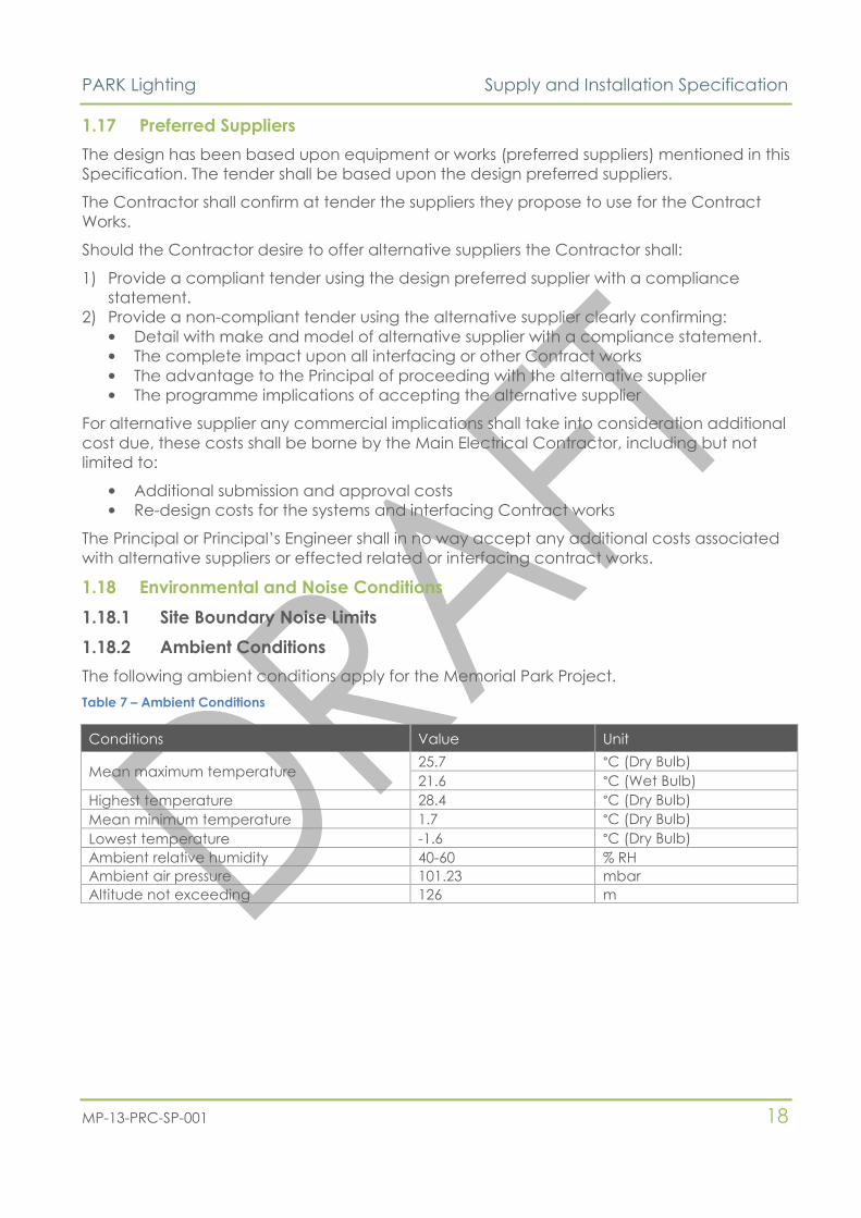
The following ambient conditions apply for the Memorial Park Project.
Table 7 – Ambient Conditions
Conditions Value Unit
Mean maximum temperature 25.7 °C (Dry Bulb)
21.6 °C (Wet Bulb)
Highest temperature 28.4 °C (Dry Bulb)
Mean minimum temperature 1.7 °C (Dry Bulb)
Lowest temperature -1.6 °C (Dry Bulb)
Ambient relative humidity 40-60 % RH
Ambient air pressure 101.23 mbar
Altitude not exceeding 126 m

PARK Lighting Supply and Installation Specification
MP-13-PRC-SP-001 19
1.18.3 Durability Requirements
Table 8 – Durability Requirements
Area Design
Life
Environmental
Factors
AS/NZS 2312
Corrosivity
Category
IP Ratings Material
Surface/ Surface Road
Lighting and
equipment
support poles
40
Rain
Wind
UV
C: Medium
carbon steel HDG600
Support brackets 40 carbon steel HDG601
LV and ELV cables 20
XLPE, underground cables
shall be PVC Neutral
Screen with heavy grade
3.2 mm PVC sheath
Photometers 10 IP66 Manufacturer's standard
HPS or LED lighting 18 IP65 Manufacturer's standard
Buried Services
LV and ELV cables 20
Moisture
Periodic
immersion in
water
D: High
XLPE or fire rated
Ducts/conduit for
cables 100
PVC
Access pits for
cables 100
Pre-cast or cast-in-situ
Access pit covers 100
Carbon steel infilled with
concrete
Electrical earthing
rods/mats 100
Copper
1.19 Dissimilar Materials
To prevent bimetallic corrosion, dissimilar metals shall not be used. Where fasteners/screws
are used, these shall be of a similar durability to the columns.
Isolate dissimilar metals that are prone to galvanic action. Examples of isolation materials
include rubber, Teflon or bitumen tape. Non-conductive materials such as elastomeric
spacers shall be used to keep aluminium alloy parts from direct contact with steel or other
dissimilar metals in the presence of moisture to avoid galvanic corrosion. Avoid metal
components coming in direct contact with cement surfaces when corrosion could occur;
for example copper & cement.
1.20 Surface treatments and Protective Coatings
The column materials must comply with the relevant design standards for durability and
shall have a life expectancy greater than the specified intended life.
Where applicable, corrosion protection shall be carried out in accordance with the
appropriate standards, for the following lighting column materials:
• Steel
All lighting columns and outreach arms shall be hot dipped galvanized in accordance
with AS/NZS 4680. The average coating mass shall not be less than 390 g/m², (equivalent
to a nominal coating thickness of 55 microns).

PARK Lighting Supply and Installation Specification
MP-13-PRC-SP-001 20
Fasteners shall be galvanized as specified in AS 1214.
All galvanizing vent holes/drainage holes shall be sealed where they could allow ingress
of rainwater.
Within the salt spray zone (ISO 9223 Category C4), the AS/NZS 2312 galvanizing
designation of HDG390 will not provide sufficient protection. For these columns, the lives
to first major maintenance must be extended by application of suitable organic barrier
coatings as recommended in Tables 5.2 and 5.3 of AS/NZS 2312.
The underside of flanged bases bolted to concrete foundations also require additional
protection against crevice corrosion and the galvanizing should also be epoxy coated
to a minimum thickness of 150µm.
The outer surfaces of galvanized ground planted lighting columns and stub bases shall
be further protected to 100 mm above finished surface level (ground or concrete) and
to the base of the column, with a continuous self-priming non-conductive barrier
coating (epoxy-mastic or similar) at least 350µm thick.
Proprietary 100% volume solids polyurethane and polyurea coatings for ground planted
columns and stub bases are available that will extend the life even further, and an NZTA
approved system should be applied where the specified service life is greater than 25
years.
Repairs to any damaged surface protection of the steelwork shall be carried out in
accordance with Section 8 of AS/NZS4680 for damaged galvanizing, except that the
maximum permitted damaged or uncoated area shall not exceed 40mm2. Repairs to
damaged organic barrier coatings shall be by reinstatement of the system.
Application and repair of all organic barrier coatings shall be in accordance with the
written instructions to be provided by the manufacturer of the coating(s). Surface
preparation prior to coating shall be by sweep blasting as specified in Appendix I of
AS/NZS4680, unless not required by the coating manufacturer (e.g. when using an etch
primer over degreased new galvanizing).
• Aluminium
Aluminium lighting columns require no specific corrosion protection other than the
application for ground planted columns of a non-porous, electrically insulating bitumen-
containing coating with a minimum layer of 250µm, or the required thickness of any
other material (e.g. helically wound polymer or petrolatum tape) that provides the same
degree of protection. The coating should only be applied after degreasing and an
appropriate treatment to ensure adhesion.
This coating should be applied to external surfaces of the embedded column section
extending to a level 100mm to 150mm above finished ground level. Internal surfaces
below ground level may be filled with clean free draining material e.g. river sand.
Aluminium in contact with concrete shall be similarly protected where moisture is
present and corrodents may be trapped between the surfaces.
Non-conductive materials such as elastomeric spacers shall be used to keep aluminium
alloy parts from direct contact with steel or other dissimilar metals in the presence of
moisture to avoid galvanic corrosion.
All parts of the enclosures shall be surface treated during manufacture to ensure protection
from the effects of moisture during transportation, prolonged storage, installation and

PARK Lighting Supply and Installation Specification
MP-13-PRC-SP-001 21
service. All materials shall be selected to minimise the potential for corrosion under their
service conditions.
Application and repair of all organic barrier coatings shall be in accordance with the
written instructions to be provided by the manufacturer of the coating(s). Surface
preparation prior to coating shall be by sweep blasting as specified in Appendix I of AS/NZS
4680, unless not required by the coating manufacturer (e.g. when using an etch primer over
degreased new galvanizing).
Full details of all paint systems offered shall be provided with the tender and shall be
approved by MPA.
1.21 Painting and Durability
Protection provided by both the column materials and the coating systems, may be shorter
than the specified intended life of the lighting column, and due consideration should be
given to the maintenance programme or renewal requirements at the planning and design
stage.
Durability is expressed in terms of the material or coating life to the first major maintenance.
The specified intended life is dependent on both the atmospheric and foundation soil
corrosivity classification for the local micro environment.
The durability of a lighting standard in its environmental exposure shall be such that it
remains fit for purpose during the design working life given the appropriate level of
maintenance.
Surfaces shall be prepared and paints or coatings applied in accordance with vendor
recommendations or coatings specialist recommendations. Paint all mild steel, proprietary
equipment, components exposed to the view of occupants and components likely to
corrode.
The contractor shall allow for the painting with a good quality paint specification of all
equipment, e.g. fans, and other plant items, mounting brackets, supports, etc., (whether of
wood or metal) particularly where corrosion or rotting is possible.
This shall include the following:
• All steel supports.
• All steel equipment and panels.
• Immediately inside all inlet and exhaust louvers.
Immediately before any equipment is delivered to the site, assembled or erected, all
surfaces which require painting and which will be inaccessible after assembly or erection
shall be thoroughly cleaned and painted.
Immediately after the installation of equipment, the sub-contractor shall check the paint
and touch up all damaged spots. If signs of rusting are apparent, rusted areas shall be
cleaned, primer painted and touched with finish paint.
After the primer coating has been approved by the Engineer the contractor shall paint the
steel pipework with a white top coat. No insulation shall be installed on the pipework until
the top coat has been inspected and approved by the Engineer.
Mitestingscellaneous steel supplied by the subcontractor shall be painted to the Engineer's
approval and finish coated such that it blends with the existing plant.
Welds made by the contractor shall be properly cleaned down before being painted.
PARK Lighting Supply and Installation Specification
MP-13-PRC-SP-001 22
Exterior painting shall not be done in rainy, damp, or dusty weather. All surfaces shall be
completely dry at the time of painting.
Where possible all shop painting shall be by spraying. Where shop applied paint surfaces
are damaged they shall be made good to "as new" condition at the completion of the
Contract.
1.21.1 Park Painting
To accommodate any painting by another Contractor for the Principal. The MEC
Contractor shall undertake their works:
• To accommodate the physical paint application without detrimental performance of
the equipment or system.
• In a sequence that allows the services to be painted, to be agreed with the Principal,
e.g. post first fix painting prior to second fix installation of equipment.
All MEC equipment and materials requiring masking shall be masked by the MEC
Contractor prior to painting, overspray that hinders the performance of the equipment or
systems shall be cleaned according to the equipment manufacturers and paint system
manufacturers’ recommended cleaning procedure
1.22 Galvanising
Galvanising shall be by hot dipped process for all components, with a thickness of zinc
coating as specified in the relevant standards. The zinc coating shall be smooth, clean,
uniform thickness and free from all defects. The preparation for galvanising and the
process of galvanising itself shall not in any way adversely affect the mechanical properties
of any coated materials. Fabricate all items with this in mind. Inadequate consideration of
the thermal stresses during galvanising will lead to distortion and subsequent rejection by
the Engineer.
Where practical, all damaged areas, e.g. all drilling, punching, cutting and bending of
parts shall be completed and all burrs removed before the galvanising process is applied.
Where this is not possible a cold galvanising system shall be used to make good the
damaged area.
1.23 Identification
1.23.1 General
Identify the Works as required by the relevant standards or regulations or as otherwise
indicated herein.
Ensure colours, letters, arrows and labels are plainly visible at the angle from which the
Works are most likely to be viewed. Use English.
1.23.2 Marking
All lighting columns and outreach arms shall be clearly and durably marked with the
following information:
• Name, identifying mark or symbol of the manufacturer
• Year of manufacture (or at least the last two digits of the year in which the marking was
affixed)
• Manufacturers model number or identification reference
• Impact classification and performance class (F if passively safe/frangible, blank
otherwise).
PARK Lighting Supply and Installation Specification
MP-13-PRC-SP-001 23
The form of marking may be either with a plate setting out in full the information above; a
plate with a decipherable single key provided by the manufacturer; a securely fixed label;
or a bar code formed either in the material or by painting or by hard stamping. The
identification plate, label or marking shall be of the same durability as the intended life of
the lighting column. The identification marking and accompanying information shall be
placed on the product itself (not on base compartment door) and be recorded in the
accompanying documentation.
Where segmented columns are used, each segment shall be appropriately marked to
enable replacement parts to be identified and ordered if damaged.
Uniquely identify such items using a numbering system conforming to that shown on the
Drawings for major equipment items. Uniquely list such items in the Operating and
Maintenance Manual.
Attach levels by instant adhesive or rivets. Do not mount labels on removable covers.
Where required by individual Specifications, proposed labels shall be submitted to the
Contractor for Review prior to production of the labels.
1.23.3 Reticulated Services – General
Identify pipework, ductwork, trunking, cable tray, conduits, etc with letter and colour
coding as listed under the individual specifications. Apply identification lettering and
banding:
• For buried and concealed runs (including in floors and walls) – the points where the
service disappears/reappears.
• For concealed runs in ceiling spaces – every 5m but at least once at point of entry to/
exit from ceiling space(s).
• For exposed runs – every 20m but at least once within each space.
The identification lettering shall be 25mm high, or half the height of the service that it
identifies, whichever is smaller.
Where services are required to be painted, extend the identification band colour
throughout the length of the service, except where otherwise directed for services that are
exposed to view.
1.24 Operating and Maintenance Manuals – General
1.24.1 General
Where there is requirement to provide an Operating and Maintenance Manual. Use authors
and compilers that are experienced in the maintenance and operation of equipment and
systems installed, and in editorial ability. Include all necessary information to enable the
Contractor to efficiently operate and cost effectively maintain the systems.
Provide three hard copies and an electronic (PDF and Excel) copy of the manual.
Electronic copies shall follow the same structure as the hard copy complete with hyperlinks
from the contents page and each section to allow speed of navigation. The electronic
copies may be provided by wither USB drive and/or CD.
All design documentation shall be as-built and submitted to the MPA for comment and
acceptance.

PARK Lighting Supply and Installation Specification
MP-13-PRC-SP-001 24
In addition, the Contractor shall submit a Test Result document that includes copies of all
tests completed throughout the Contract.
The MPA Engineer will review the as-built Test Result documents. Any comments will be
acted upon by the Contractor and a final set issued before Practical Completion is
achieved and a certificate to this affect issued by the MPA Engineer. The Contractor shall
also update any affected NZTA records or systems in accordance with current practice.
1.24.2 Format
The format of the O&M Manuals shall comply with the following:
Table 9 – O&M Format
Format Requirement
Binding A4 size, D type, 3 ring binders with black plastic or vinyl faced hard covers.
Cover Title
“MEMORIAL PARK INNER CITY BYPASS” for MEMORIAL PARK ALLIANCE 30 point
Operating and Maintenance Manual 24 point
(Name of service) Services 24 point
Spine
“MEMORIAL PARK UNDERPASS” 24 point
Operating and Maintenance Manual 16 point
(Name of service) Services 16 point
Volume (number) 16 point
Lettering Gold HELVETICA X/BOLD CONDENSED 20 UPPER CASE. Silk screen or hot foil blocking
printing process.
Paper 80 gsm copy paper. Xerox or other long-lasting copying process.
Dividers Use durable index tab dividers between each element, with the section number
typed on the tab and section name typed on the divider.
Contents List Provide at front of each volume, listing contents of all volumes. Provide at front of
each section, listing contents of each section.
1.24.3 Content
Table 10 – O&M Content
Section Sub-section To contain
1. Introduction 1.1 Sub-contractors/
Suppliers/ Specialist
Trades/ Contractor
to this contract.
— Names
— Addresses
— Phone
— Facsimile
1.2 Termination of
defects liability.
Information in table format of different equipment
supplied and expiry dates for defects liability
1.3 Brief description
of Purposed of
Manual.
Include an explanation of the purpose of the manual
and a brief description of each section included in the
manual. Describe that in general, Section 3 (Operating
Instructions) details instruction for the building owner and
Section 4 (Routine Maintenance) is intended for

PARK Lighting Supply and Installation Specification
MP-13-PRC-SP-001 25
Section Sub-section To contain
engineering personnel.
1.4 Brief description
of overall system.
Provide a description of the overall installation covered
by the manual.
1.5 External parts
and components.
Where parts of the installation are supplied under the
other contracts or by the owner, related information shall
be included in the manual or expressly excluded.
1.6 Table of
contents.
Table of contents for manual
2. Description of
the Systems
2.1 Description of the
system installed
This section is to have a technical description of each
individual system, including function, normal operating
characteristics, limiting conditions, and interfaces with
other installations. Describe type and location of major
equipment.
2.2 External parts
and components.
Where parts of the installation are supplied under other
contracts or by the owner, or were existing, describe how
the Works relate to those parts.
3. Operating Instructions Including but not limited to
— Procedures necessary to operate the plant under
normal operating conditions.
— Other operations which may be carried out by
unqualified personnel under abnormal or emergency
conditions.
— Operating procedures under seasonal changeovers.
— Full operational instructions and warnings.
— Operational set points.
— Fault finding procedures.
— Day-to-day routine operations.
— Explanation of alarm conditions and record of alarm
set points.
4. Routine Maintenance Routine maintenance descriptions on every element of
the system installed. This shall include
— Detailed maintenance and servicing instructions.
— Recommended spares list.
— Recommended periodic maintenance.
— Recommended torque settings.
5. Manufacturers Details A table detailing the New Zealand agents for all of the
components supplied.
6. Equipment Details Including but not limited to
— Part numbers of all equipment modules.
— Complete internal wiring and component drawings
including individual assemblies and cards.
— Component data sheets for all of the components
supplied.
—
7. Testing and Commissioning Results Including but not limited to
— Record all physical details and cable sizes.
— Have a Set-Up Sheet documenting all
optional/adjustable settings.
— Contain a completed copy of the factory
commissioning "Check-Sheet".
— Contain a complete copy of the site commissioning
‘Check Sheet’.
8. Certificates and Warranties Including but not limited to
PARK Lighting Supply and Installation Specification
MP-13-PRC-SP-001 26
Section Sub-section To contain
— Copy of the Certificate of Compliance (COC).
9. Post Completion Modifications and
Adjustments
List of all post completion modifications that have been
carried out on system.
10. As-built drawings Drawings in A3 format. Hard copy manual to include a
set of Construction Record Drawings legibly reproduced
on A3. Fold to A4 size such that Drawings can be
unfolded without removal from ring binder.
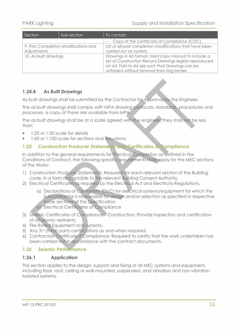
1.24.4 As Built Drawings
As built drawings shall be submitted by the Contractor for Approval by the Engineer.
The as built drawings shall comply with MPA drawing protocols, standards, procedures and
processes, a copy of these are available from MPA.
The as built drawings shall be at a scale agreed with the engineer, they shall not be less
than:
• 1:20 or 1:50 scale for details
• 1:50 or 1:100 scale for sections and elevations
1.25 Construction Producer Statements and Certificates of Compliance
In addition to the general requirements for Practical Completion as defined in the
Conditions of Contract, the following specific requirements shall apply for the MEC sections
of the Works:
1) Construction Producer Statements: Required for each relevant section of the Building
code, in a form acceptable to the relevant Building Consent Authority.
2) Electrical Certificates as required by the Electrical Act and Electricity Regulations.
a) Declarations of Conformity (DoC) for electrical systems/equipment for which the
Subcontractor is responsible for design and/or selection as specified in respective
trade sections of this Specification.
b) Electrical Certificates of Compliance
3) Seismic Certificates of Compliance – Construction: Provide inspection and certification
of all seismic restraints.
4) Fire Rated Equipment and systems.
5) Any 3rd (third) party certifications as and when required.
6) Contractors Certificate if Compliance: Required to certify that the work undertaken has
been carried out in accordance with the contract documents.
1.26 Seismic Performance
1.26.1 Application
This section applies to the design, support and fixing of all MEC systems and equipment,
including floor, roof, ceiling or wall mounted, suspended, and vibration and non-vibration
isolated systems.

PARK Lighting Supply and Installation Specification
MP-13-PRC-SP-001 27
1.26.1.1 Park works
The seismic design and installation compliance criteria for the Park MEC works shall include
but not be limited to:
1) The greater of:
a) Design for seismic actions (forces and displacements) in accordance with NZS 4219
(2009) and this Specification, or
b) Design for seismic peak ground acceleration of 0.74g and this Specification
2) Where the requirements of this Specification are in addition to the requirements of NZS
4219, the requirements of this Specification shall apply. (Additional requirements
extracted from ASHRAE, Tauby et al “Practical Guide to Seismic Restraint”, with the
objective of reducing the need for specific seismic design in accordance with NZS4219
Section 4.)
3) Supports and fixings include structural members, braces, skirts, legs, saddles, pedestals,
cables, guys, stays, snubbers, tethers and elements forged or cast as part of the
component.
4) Accumulated loads: The accumulated load of multiple systems/equipment to any given
support (with or without seismic restraint) shall be limited so as not to exceed the load
limitations of the support assembly or those structural load limitations established by the
Engineer.
Certificates as required by Standards, this Specification or the specific technical
specification.
1.26.2 Design
General
Any designs by the Contractor shall include
1) Design for seismic actions (forces and displacements) in accordance with NZS 4219
(2009) and this Specification. Where the requirements of this Specification are in addition
to the requirements of NZS 4219, the requirements of this Specification shall apply.
(Additional requirements extracted from ASHRAE, Tauby et al “Practical Guide to
Seismic Restraint”, with the objective of reducing the need for specific seismic design in
accordance with NZS4219 Section 4.)
2) Supports and fixings include structural members, braces, skirts, legs, saddles, pedestals,
cables, guys, stays, snubbers, tethers and elements forged or cast as part of the
component.
3) Accumulated loads: The accumulated load of multiple systems/equipment to any given
support (with or without seismic restraint) shall be limited so as not to exceed the load
limitations of the support assembly or those structural load limitations established by the
Engineer.
1.27 Alternate Designs
Designs alternate to the lighting design presented on the Drawings may be provided to the
designer for consideration. Design alteration shall only be in the form of luminaires (NZTA
approved), all other elements of design that require co-ordination with the civil works shall
remain. Alternate designs must meet the following requirements:
• Utilize the same power supply and control architecture as shown in the drawings;
• Be compatible with the documented system operation and provisions; and
• Meet the requirements of this specification and the Project Documents.

PARK Lighting Supply and Installation Specification
MP-13-PRC-SP-001 28
This section outlines the Design Criteria to which the lighting installation must adopt and
must comply. It is noted that, should an alternate design be adopted, the Design
Documentation requirements of the Project Documents may apply depending on the level
of deviation from the current presented design. It is further noted that design calculations
will be required and submitted to URS for review.
1.28 Site of the Works
The site of the works is as described in the specification.
Access times for delivery shall be co-ordinated with the Principal.
Ensure that the appropriate licences and approvals are obtained for work in those
particular areas.
1.29 Drawings
The following drawings are associated with and should be read in conjunction with this
document. Where a conflict exists between the drawings and this Specification, the
Engineer shall be consulted for a determination.
Table 11 - List of associated drawings
Drawing Number Drawing Title
MP-10-100 COVER SHEET & KEY PLAN
MP-10-101 DRAWING LIST & LEGEND
MP-10-111 SITE POWER LAYOUT (GRID 01-19)
MP-10-112 SITE POWER LAYOUT (GRID 18-34)
MP-10-113 SITE LIGHTING LAYOUT (GRID 01-19)
MP-10-114 SITE LIGHTING LAYOUT (GRID 18-34)
MP-10-115 PARK DB SITE PLAN
MP-10-116 PARK DB GENERAL ARANGEMENT
MP-10-117 DB-P1, DB-P1 EV, DP-P1 AWM & DB-P2 SCHEMATIC
MP-10-118 DB-P1 LIGHTING CONTROL SCHEMATIC
MP-10-119 DB-P2 LIGHTING CONTROL SCHEMATIC
MP-10-120 LIGHTING DETAILS 1
MP-10-121 LIGHTING DETAILS 2
1.30 Approvals
Details of fully compliant designs including calculations confirming compliance with the
design criteria and drawings shall be submitted for approval by the Engineer before
commencing manufacture of the order.
Alternatives shall only be considered if submitted and confirmed as fully compliant, the
onus shall be on the Park Lighting Sub-contractor to proof full compliance with the design
and specification criteria.
The Park Lighting Contractor shall submit a sample of each type of light fitting and its
associated bracket system for approval by the Engineer prior to commencing manufacture
of the order.

PARK Lighting Supply and Installation Specification
MP-13-PRC-SP-001 29
2. SUPPLY OF EQUIPMENT AND MATERIALS
2.1 Shipment
Equipment shall be packed to prevent damage in transit. Packages shall be clearly
labelled with:
1) Order number.
2) Equipment number.
3) Package number and total number of packages.
4) Gross weight.
All equipment shall be packaged in a manner suitable for handling during transport and
storage to avoid damage components or any painted surfaces.
The Contractor shall submit their proposals to the Principal for protection of equipment
during transit. The responsibility for safe and damage free delivery remains with the
Contractor.
Heavy and bulky equipment shall be provided with adequate lifting fixtures to facilitate
ready handling during transit and on arrival at site. All equipment shall be shipped below
decks.
2.2 Materials
Materials include all building elements, plant, equipment, machinery, components, fluids,
consumables and the like, that form part of the Contract Works.
Materials shall be:
• New unless specified otherwise.
• To the latest and most appropriate technology.
• Suitable for the intended use.
• Proven in service.
• Compatible with surrounding and joining materials.
• Suitable for installation in the intended space with allowance for long term
maintenance access.
• Supported by locally available spares and service.
• Consistent in brand, type and size for each material item.
• Supported by appropriate servicing facilities and locally available spare parts.
Deliver materials to site with the maker's label intact and protect all materials. Where
practible materials should be delivered “just in time” for the required works, with minimal
storage durations. Protection shall include safe storage and preventing ingress of foreign
material, or damage to internal and external parts. Replace or make good any damaged
materials.
Where any material is mentioned by a trade name or by any other specific reference, it is
for the purposes of indicating suitable standards of quality (including but not limited to
finish, durability and serviceability), space requirements and structural loading for the
purpose intended, and for no other reason. Material characteristics other than those
specifically covered by the Drawings and Specifications, shall be at least equivalent to
those of any mentioned trade name, or if no trade name is mentioned, typical of the
respective material kind.
The Contractor shall:

PARK Lighting Supply and Installation Specification
MP-13-PRC-SP-001 30
• Provide consistent type, brand, size, quality and appearance for the whole quantity of
each material or equipment item.
• Deliver materials and equipment to the Site with the Manufacturer’s label intact and
with the Manufacturer’s written installation procedures.
• Store and protect all materials and equipment furnished in connection with the Works.
Protection shall include preventing moisture and foreign substances from entering the
working parts or damaging the structure or finish of materials and equipment. Make
good or replace, at the Engineers discretion, any damaged materials or equipment
from whatever cause, at no extra cost to the Principal.
2.3 Packing Requirements
All equipment shall be carefully packed and secured for transport to ensure that the
equipment is protected from all dust and climatic conditions during loading, transport,
unloading and subsequent storage in the open. Equipment shall be suitably packed and
protected against vibration, movement and shock that may occur during loading and
transport. Particular care in packing shall be taken when the equipment is transported by
road.
Instruments and other fragile items shall be packed separately. All items that include
delicate equipment shall be sealed in polythene sheeting. Silica gel desiccant or vapour
corrosion preventive shall be inserted within the polythene packing.
All packaging shall comply with the New Zealand government customs and quarantine
requirements.
2.4 Storage
All equipment, whether fabricated or not, shall be stored above ground on pallets, skids or
other supports and adequately protected from the weather and corrosion. Items that are
damaged will be subject to rejection.
2.5 Identification and Documents
All equipment supplied under this Contract shall be clearly identified on the outside of any
case with the type and number of items contained therein and the gross weight. Large
crates are to be marked on three sides, and smaller crates which can be easily
manhandled are to be marked on at least two sides.
The names of haulage firms, shipping companies, shipping agents, customs authorities and
any special handling firms shall be advised to the Principal before the equipment is
despatched. One copy of each applicable shipping specification, packing list, mass note,
packing note and the relevant control numbers of consignment notes, waybills, bills of
loading, customs clearance certificates, tranship notes and the like shall be forwarded to
the Principal as each paper required is raised, together with expected dates of departures
and arrivals en route.
2.6 Spares
Spares necessary to support normal operation and maintenance requirements for a period
of 12 months shall be provided under the Contract.
Spares shall be:-
1) Re-stocked to the recommended inventory levels on completion of the warranty period
2) Suitably packed for long term storage.

PARK Lighting Supply and Installation Specification
MP-13-PRC-SP-001 31
3) Indelibly labelled on the outside of the packaging so that the part and its purpose can
be accurately identified without unpacking.
2.7 Date Processing
Hardware, software and firmware products and systems provided under this Contract,
including proprietary equipment incorporating date aware electronic controls or
embedded microchips, shall accurately process date data (including, but not limited to,
calculating, comparing and sequencing) from, into and between centuries, including leap
year calculations and day light savings times, when used in accordance with the product
documentation provided by the Supplier.
2.8 Power Quality and Electromagnetic Interference
The Supplier’s attention is drawn to supply voltage variations at the Site. These may be
expected to occur beyond the normal limits referred to in the Electricity Regulations. These
variations may include harmonics, surges, sags and impulses (spikes) and may be
generated either outside or within the installation.
Provide appropriate devices such as power conditioners, voltage stabilisers, harmonic filters
or surge diverters as necessary to protect all equipment supplied under the Contract which
may be sensitive to supply voltage variations. The Supplier shall be responsible for the
adequate selection and provision of all necessary protective measures.
The Supplier’s attention is also drawn to the high electromagnetic environments caused by
radio transmitters used by Police, Fire Brigade, and Security. Mobile Phone Companies and
other services, which may cause premature failure of or interference with electronic
equipment. Provide all necessary earthing, screening, protection etc, so that the system will
operate satisfactorily and without degradation in this environment.
Where cable routes are not designated on the Drawings, route cables so as to minimise the
effects of electric and magnetic fields on other equipment. Run single core cables in trefoil
with the neutral conductor adjacent the phase conductors. Route cables clear of
computer or VDU suites and the like. Route communication, control and instrumentation
cables using twisted screened cables as a minimum.
2.9 Construction Record Drawings – Equipment
2.9.1 General
Provide Construction Record (As-Built) Drawings recording the specific design details for all
equipment items as listed under the individual Specifications.
2.9.2 Submission
Submit the information to the Principal for review four weeks prior to the date of
completion.
2.10 Training
The Contractor shall submit for review by the Principal the Training Plan. It shall include as a
minimum a range of staff for which training is recommended and a training plan shall be
submitted by the Contractor to the Principal at least three (3) months prior to the issue of
the Taking-Over Certificate for the Works.
The Contractor shall provide input relating to the Works to the Training Plan in accordance
with the overall philosophy for training.

PARK Lighting Supply and Installation Specification
MP-13-PRC-SP-001 32
The Training Plan shall be prepared based on, but not limited to, the System Operations Plan
and the System Maintenance Plan.
2.10.1 Training Plan
Where required by the individual Specifications, the Contractor shall include the cost of the
services of qualified instructor(s) to instruct the Principal and Owner’s operating and
maintenance personnel in the operation, adjustment, care and maintenance of all
equipment required for fully functioning equipment or systems.
Instruction shall be performed at a time approved by the Principal after all equipment and
systems are installed, completed, adjusted and operating to specific requirements.
The Contractor shall notify the Principal when instructions will be given.
Qualifications of instructor(s) shall be subject to the approval of the Principal.
2.10.2 Training Equipment
With the prior agreement of the Principal, the Contractor may use the Permanent Works
being erected, tested or commissioned for the training of the Principal’s staff. In general the
Contractor shall not use spare parts for this purpose.
The Contractor’s Training Plan shall be supplemented by hands on experience, alongside
the Owner’s personnel, during the testing and commissioning of the Works.
Training course notes shall be entirely compatible, and, where appropriate, cross-
referenced to the manuals supplied by the Supplier as part of the Operation and
Maintenance documentation.
The Contractor shall provide such written or printed matter, functional equipment, samples,
models, cutaway equipment, slides, films and other instructional material as may be
necessary for training. Such equipment and material shall remain the property of the
Principal and shall be sufficient both for the persons trained by the Contractor and for those
to be subsequently trained by the Principal’s instructors.
The Contractor shall provide a trainer’s guide for each training course. The guide shall
include the course agenda, objectives, list of resources and facilities required, detailed
lesson plans, presentation notes, discussion guides, training aids and job aids, test papers,
criteria and methodology for testing and assessment, and all other things that will enable
the Principal’s own trainers to carry out repeat or refresher courses in the future.
2.10.3 Training Manuals
All project specific training documentation shall be written in concise and simple English
making maximum practicable use of diagrams, drawings, photographs and screen dumps.
The Training material shall be prepared on the basis that the actual operating and
maintenance manuals will be the foundation of the training courses.

PARK Lighting Supply and Installation Specification
MP-13-PRC-SP-001 33
3. ON SITE INSTALLATION
3.1 Free Issued Equipment
The Contractor shall inspect any equipment or material supplied by the Principal or any
other party prior to any work commencing. Any such items that are noted to be damaged
or otherwise non-compliant with the specifications provided shall be brought to the
attention of the Principal at the earliest opportunity.
In the event that any equipment is damaged during the Works by the Contractor, the
Contractor shall repair the damage at their cost to the satisfaction of the Principal.
3.2 Contractor Supplied Documents
Any anomalies between documents must be referred to the Principal for resolution as soon
as practicable and prior to construction.
3.3 Material Substitution
A substitution of materials or equipment specified under the contract may be proposed by
the Contractor if:
• Specified products are not available.
• Indicated lead times may cause delay to the Works.
• Substitute products are considered to be equivalent or superior to those specified.
The Contractor shall provide all information necessary for the Principal to be able to
adjudge suitability of the substitution.
The Principal shall not be obliged to accept any substitutions unless a specified product is
not available and a substitute has been assessed to be suitable.
No substitution of materials or equipment shall be made without prior written approval by
the Principal.
3.4 Coordination and Setting Out
The Contractor shall install the Works according to the “Issue for Construction” Drawings.
However, the Contractor shall be responsible for the detailed setting out of his section of
the Works so as to:
• Co-ordinate with other Trades, particularly with respect to other building services,
including area by area discussions with all appropriate Trades, having all up to date
Drawings with them at these discussions. If the Principal is not present at any of these
area by area discussions, then brief notes of the conclusions reached at that discussion
are to be prepared by each Trade and submitted to the Principal to enable it to check
that this process of setting out discussions, is working properly.
• Locate the Works in the spaces allocated for the purpose with suitable access and
clearances for normal and long term operation and maintenance requirements.
The Contractor shall confirm all dimensions on site prior to fabrication.
Where a discrepancy exists which prevents successful setting out and co-ordination, obtain
clarification instructions. Should the Contractor consider that it is not possible to coordinate
the setting out of their work in the space available, they shall advise the Principal who shall
designate which Trade shall sketch a proposed solution and submit it to the Principal for
consideration and for the Principal to issue an instruction on how to proceed.

PARK Lighting Supply and Installation Specification
MP-13-PRC-SP-001 34
The Contractor shall discuss upcoming site work on a daily basis with the Principal to ensure
that their works do not adversely impact on other subcontractors or separate contractors
working on the Project
No account will be taken of any abortive manufacture, fabrication or installation work
which has been due to the failure of the Contractor to carry out proper setting out and co-
ordination.
3.5 Installation
Workmanship shall be:
• In accordance with best modern trade practice.
• Carried out by appropriately qualified and experienced tradesmen and supervised
apprentices.
• Carried out under the supervision of a competent foreman.
• To a high standard of construction and leave an efficient, robust, tidy and fully
operational installation.
Install materials and equipment in accordance with the manufacturer's written instructions.
Provide labour and materials required to clean, treat, shim, grout, adjust, alter, support or
do any other work on materials and equipment which the manufacturer, or his agent, may
consider necessary to achieve a satisfactory installation.
Provide proper connections and interfacing between relevant materials and equipment,
such as to avoid such interfacing causing damage to or adversely affecting the
performance or durability of the Works.
If materials are required to comply with product certification schemes, use them in
accordance with the certification requirements.
Where material samples are required, incorporate in the works only those materials which
match the approved samples.
Arrange reticulated services to run parallel with adjacent services, building elements, and
grid lines where possible and practical.
Ensure access to services is not impeded.
Provide for movement in both structure and services.
3.6 Fire Stopping
The Contractor shall provide fire stopping around and within the Works passing though fire
rated compartment walls, ceilings or roofs. Only fire stopping materials certified and
approved by the Contractor shall be used.
The Contractor shall maintain the continuity and effectiveness of fire separations around
penetrations, and in gaps between or within fire rated building elements, by the use of
approved fire stops. Fire stops shall have certified fire resistance ratings (FRR) no less than
that required for the separation in which they are installed.
Fire stop certification shall be based on tests carried out by an independent laboratory in
accordance with internationally recognised fire resistance rating test procedures.
Select fire stop materials that are appropriate for the type and size of the gap or
penetration, and for the type of material and construction used in the fire separation.

PARK Lighting Supply and Installation Specification
MP-13-PRC-SP-001 35
Materials and methods of installation used on site shall be identical to those of the
prototype used in their FRR tests.
Fire stop materials shall generally include:
• Plastic pipes, including plastic water pipes: Fire rated intumescent collars (closures).
• Metal pipes: Fire seal gaps between pipes and fire separation with a material capable
of maintaining the fire rating.
• Electric cables: Fire seal gaps between cables and fire separation with a material
capable of maintaining the fire rating.
Fire stops for penetrations in hollow construction shall protect the penetration over the full
depth of the fire separation.
Fire stops shall be fixed and supported such as to:
• Be restrained from moving or parting from the surfaces of both the penetration and the
fire separation during a fire.
• Allow for normal expansion and contraction of the services that run through the
penetration.
Specific requirements for penetrations in fire rated dry wall and floor construction (in
addition to the above requirements) shall include:
• Through penetrations: Provide trimmers around penetration to support the fire rated
lining material.
Partial penetrations (e.g. for light fittings, socket outlets, switches and the like): To be in
accordance with the specific detail of the dry wall/floor system manufacturer.
3.7 Construction Record Drawings – On site Installations
3.7.1 General
Provide As-Built (Construction Record) Drawings recording the Works as installed by the
Contractor. Show the as installed locations and details of building elements, plant,
equipment, cables, piping, ductwork and the like. Include schematic drawings of each
system.
Where identified by the individual Specifications, update existing Construction Record
Drawings recording the Works as installed by the Contractor. Do not create new Drawings if
it is practicable to record the work by updating existing Drawings.
Retain one “Mark Up” set of the construction Drawings at the Site. Neatly mark up all
changes to the installed work from the Drawings, including all amendments under site
instructions or contract instructions, as they occur. These prints shall be available for
inspection on request.
All CAD files are to comply with MPA CAD processes, procedures and formatting.
All drawings shall have the appropriate external reference files (Xrefs and Images)
referenced into the drawings (e.g. “Xref …. overlayed”). External reference files shall be
overlayed to Modelspace with the insertion point being 0,0. Do not alter any external
reference file names. Do not include a path name to any attached file in the drawing.

PARK Lighting Supply and Installation Specification
MP-13-PRC-SP-001 36
.

PARK Lighting Supply and Installation Specification
MP-13-PRC-SP-001 37
4. INSPECTIONS, SNAGGING AND DEFECTS
The Contractor’s works shall be subject to review by the Engineer to assess if the Works
comply with the Contract.
4.1 Inspection prior to closing up
The Contractor shall via the Principal advise the Engineer that works are to be closed up
such that MEC or ITS services will no longer be visible for snagging.
10 working days’ notice shall be provided to the Engineer.
No works shall be closed up with the Engineer’s approval.
The Engineer shall attend and advise if the works can be closed up, if the works do not
meet the Contract requirements the Contractor shall remedy the works and invite the
Engineer to inspect the works again, the process shall be repeated until the Engineer is
satisfied.
Agreement to closing up by the Engineer does not alleviate the Contractor of their
responsibilities.
Should works be closed up without the Engineer’s agreement the Contractor shall arrange
for the Principal to open up the works for inspection and make good following agreement.
The cost of opening up and making good shall be at the Contractor’s expense and not
passed onto the Principal.
4.2 Snagging
The Engineer shall be advised by the Contractor via the Principal that the works or a sub-
section of the works are available for inspection and snagging, 10 working days’ notice
shall be provided.
At the time the Contractor advises the works are available for snagging the Contractor shall
provide their own snag clearance schedule demonstrating that they have inspected their
own works and cleared known snags.
The Engineer will attend site and review the works, passing a list of snags to the Contractor
while on site.
The Contractor shall be responsible for maintain a list of snags and logging the clearance of
the snags against a master schedule. Snags shall not be cleared unless agreed by the
Engineer.
Following rectification of the snag the Contractor shall invite the Engineer to re-review the
works, demonstrating the snag is cleared. This process shall be repeated until the snag is
agreed as cleared by the Engineer.
All snags shall be agreed as cleared by the Engineer prior to the Contract works being
offered or accepted as complete, and in any case prior to witnessing or testing.
Cosmetic snags that do not affect the operation or performance of the equipment or
systems shall be able to be cleared during testing, commissioning or witnessing so long as
the Contractor can demonstrate the clearance will not affect the equipment or system
performance.

PARK Lighting Supply and Installation Specification
MP-13-PRC-SP-001 38
4.3 Defects
Defects in the Contractor’s works shall be advised by the Contractor or Engineer to the
Principal as soon as they arise. Corrective action shall be agreed with the Engineer prior to
installation.
Defects occurring before the Contract works are agreed complete shall be cleared prior to
the Engineers Witness testing or operational testing if the defect arises during the witness
testing.
Defects according flowing Contract works completion shall be cleared according to the
Contract.

PARK Lighting Supply and Installation Specification
MP-13-PRC-SP-001 39
5. TECHNICAL
5.1 LV Power Distribution System
The system objective is to provide a safe and efficient LV power distribution system, which is
designed and installed in accordance with the specified standards and regulations. The LV
power distribution system is deemed to include the entire electrical distribution cabling,
cable joints, connection boxes and all switchboards.
The objective is to include all equipment, wiring, switching devices and other accessories
from the source of supply to the relevant distribution boards and to the end-use equipment.
All cables, switchgear and devices shall be dimensioned in accordance with NZS 3000 and
the current supply authority regulations. In particular all cables and switchgear shall be
suitably rated for the maximum load and the electromagnetic stresses arising from
prospective short circuit currents and earth fault currents under the particular installation
conditions.
Ensure the earthing and bonding of equipment and the earth leakage devices comply with
the requirements of AS/NZS 3000 and the current supply authority regulations to ensure
there is no danger to persons under fault conditions.
Obtain all necessary approvals and agreements from the supply authority and any other
relevant authorities.
Protective devices shall be suitable for protection against overload, short circuit and earth
fault current.
Effective disconnection devices shall be provided for easy and rapid operation in case of
danger and, suitable for disconnection during maintenance, testing, fault detection and
repair.
The arrangement of the installation shall be so as to precent mutual detrimental;
interference between different electrical installations and non-electrical installations, which
take into account electromagnetic interference.
5.2 Design Parameters
Footing design for the lighting columns shall be submitted by the column supplier for
approval by the designer.
All poles fitted with 17° up-cast light masts shall be fitted with a tilt adaptor, allowing a 10
degree luminaire up-cast to be achieved as required.
Lighting columns to local roads shall be co-ordinated with local councils. Contractors to
allow for any tie-ins that may be required during the construction process and/or temporary
works.

PARK Lighting Supply and Installation Specification
MP-13-PRC-SP-001 40
5.3 Permanent Lighting Design
5.3.1 Maintenance Factors
Following the procedures outlined in ASNZ1158 (series) the maintenance factors (MF) for
lighting are:
Table 12 – Maintenance Factor(s)
HPS Fluoro (T8) LED
Lamp Lumen Depreciation Factor 0.91 0.91 0.95
Luminaire Dirt Depreciation Factor 0.88 0.88 0.89
Room Surface Dirt Depreciation 0.87 0.87 0.87
Maintenance Factor 0.70 0.686 0.74
AS/NZS Recommendation 0.80 0.80 0.80
5.3.2 Lighting Control
Park’s associated lighting to shall be controlled via a timer in series with photometer(s)
located on the roof of UAB building with manual override switch.
State Highway associated lighting control is via ripple control by Wellington Electricity.
5.3.3 Lamp Lumens
The lighting design LED luminance used for street lighting:
The lighting design has used the following LED Lumen outputs (where required to show
compliance with the annotated standards.
5.3.4 Quantities
Provide a price for the provision of Park Luminaires meeting the specification requirements.
Quantities shall be initially based on the drawings and the price offered shall not vary per
unit for quantity changes of ± 50. Cost shall include preliminary samples for approval; full
witnessed photometric testing at an independent testing laboratory, with electronic format
test results and full shop drawing submittal.
Price should reflect installation of body, site protection and installation of louvres, and clean
to achieve practical completion.
5.4 Luminaire performance
5.4.1 Luminaire construction
5.4.1.1 General
All materials, accessories and other related fitting parts shall be new and free from defects
which in any manner may impair their character, appearance, strength, durability and
function, and effectively protected from any damage from the time of fabrication to the
time of delivery and until final acceptance of the work.
The luminaire enclosures shall be fabricated special section. Enclosures may be constructed
of other metals, provided they are equivalent in mechanical strength and acceptable for
the purpose.

PARK Lighting Supply and Installation Specification
MP-13-PRC-SP-001 41
All metal work shall be free from tool marks and dents and shall have accurate angles bent
as sharp as compatible with the gauges of the required metal. All intersections and joints
shall be formed true of adequate strength and structural rigidity to prevent any distortion
after assembly.
Housings shall be so constructed that all electrical components are easily accessible and
replaceable without removing fittings from their mountings, or disassembly of adjacent
constructions.
The copper content of all die cast aluminium luminaires shall be a maximum of 0.1%.
Minimal cut-off optic luminaires with an internal seal safe IP66 lamp chamber for optimum
light output to be used.
All castings shall be exact replicas of the approved patterns and shall be free of sandpits,
blemishes, scales and rust, and shall be smoothly finished. Tolerance shall be provided for
any shrinkage of the metal castings in order that the finished castings will accurately fit in
their designated locations.
All lamp sockets in luminaires shall be suitable for the indicated lamps and shall be set so
that lamps are positioned in optically correct relation to all lighting fitting components.
All luminaires shall be completely wired at the factory.
Yokes, brackets and supplementary supporting members needed to mount luminaires to
carrier channels or other suitable ceiling members shall be furnished and installed by this
Specialist Supplier.
For stainless steel fittings, all fastenings shall be stainless steel.
5.4.1.2 Temperature Rating
All luminaires and ballasts must operate within the temperature limits of their design and as
specified by British Standards Institute in the applications and mounting conditions herein
specified.
5.4.1.3 Voltage Rating
All luminaires (including all internal components) must be nominally rated 230V, single
phase, 50Hz. Luminaires must be capable of continuous operation anywhere in the range
of 230VAC +10% to -6% at the rated ambient temperature as described in Section 6.4. For
the avoidance of doubt this means up to a constant supply voltage of 253VAC.
5.4.1.4 Ballasts
Ballasts shall comply with AS/NZS 61347.2 and AS/NZSCISPR 15 and have an insulation rating
not inferior to Class H, in accordance with IEC 60085.
5.4.1.5 Igniters
Igniters shall comply with AS/NZS 61347.1, AS/NZS 61347.2.1 and AS/NZS 60927 and shall be
of the solid state type.
5.4.1.6 Control Gear
Control gear shall be high frequency, mounted in luminaire body, sized and arranged to
give maximum circuit watts per lamp at unity ballast lumen factor and no less than 0.95
lagging power factor. All control gear and lamp connectors to be interconnected using
high temperature, LSF cable. High frequency control equipment to have the performance
specification as follows:

PARK Lighting Supply and Installation Specification
MP-13-PRC-SP-001 42
5.4.1.7 Lamp Protection
Lamp protection shall be provided to prevent any failed tube from repeat starting
attempts.
Each ballast to be provided with over-voltage protection for short duration voltage pulses
as defined by DIN/VDE 0160.
Each high frequency ballast shall comply with the requirements of the standards listed in the
General MEC Specification, including but limited to BS800, BS5394, CISPR15, VDE 0107 and
VDE 0875(B) for mains conducted and airborne radio frequency interference.
5.4.1.8 Performance
Luminaires as described in this specification shall be installed at spacing as indicated on the
drawings. Luminaire output to design performance requirements shall be demonstrated by
the Park Lighting Contractor.
5.4.1.9 Independent Photometric testing
The Park Lighting Contractor shall include for and have each luminaire type tested by an
independent testing authority with calculations to support the test results.
The independent laboratory testing results shall be made available for the Principal’s
Engineer’s approval and submitted such that approval is obtained prior to manufacture
and delivery of the luminaires.
The independent testing laboratory shall be a certified laboratory and the report shall be
provided with paper and electronic copy of the results, including IES file format for lighting
modelling.
Independent means independent of the Park Lighting Contractor, Wholesaler, Supplier or
Manufacturer, or an associated company.
Certified means certified by an internationally recognised certification body for
photometric performance, ingress protection, vandal resistance.
Tests shall include photometric performance over the environmental condition and
temperature expected.
5.4.1.10 CIDs
Each luminaire shall be complete with horizontally arranged which shall be as approved
suitable for operating from specified control gear.
Lamps shall be equally spread in back box to maximise lumen output.
Lamp type shall operate within the optimum lamp output range
5.4.2 Luminaire performance
The luminaires shall meet or exceed the required lighting technical parameters (LTPs)
required by AS/NZS 1158. The drawings indicate a design/luminaire layout, based on
currently available in the market place, Park luminaires that are compliant with this
standard. Detail calculations are required to be submitted to show the proposed luminaire
will likewise comply with the LTPs.
5.5 Vibration
The lighting columns and the associated luminaires and lamps mounted on the columns
shall be designed, as a system, to withstand the vibration that is typically induced by wind,

PARK Lighting Supply and Installation Specification
MP-13-PRC-SP-001 43
and adjacent traffic, as well as seismic requirements in accordance with the TNZBM, and
AS/NZS 1170.
5.6 Cables and Wiring
5.6.1 General
The installation of cables and wires unless otherwise specified, shall be in accordance with
the requirements of the New Zealand Wiring Regulations and manufacturers requirements.
Jointing of cables shall not be permitted, without notifying the designer.
Any cabling passing through concrete (e.g. column foundations) shall be run in conduit
with large sweep radius bends. Cables shall generally be run in conduits unless otherwise
specified.
The contractor shall be deemed to have visited the site and made allowances for
coordination of all trenching, thrusting, re-instatement work etc.
All underground cabling shall be buried to a minimum of 600mm cover. Supply and install
cable pits as shown in drawings and/or where considered necessary to complete the
works. All cable pits in sealed areas shall be ACO “Polyconcrete” with lock down
“Rhinocast” lid or approved equivalent. All other cable pits shall be ACO plastic pit with a
“Polyconcrete” lid and shall be positioned in areas unlikely to be driven over.
The Contractor shall be responsible for the protection of cables during storage and
installation. Any repairs to damaged cables shall be authorised by the Designer prior to any
remedial works to repair cables.
During handling and installation care shall be taken to ensure that the cables are not bent
to an extent which may cause undue stress on the insulation or sheathing but in any case
not less than the minimum internal radius specified by the manufacturer. Cables shall not
be drawn through their minimum radius during installation.
All cable ends shall be kept sealed until the cable is required and any cables delivered
unsealed shall be tested and checked for suitability prior to resealing and accepting the
cable for use. Reseal after cutting and before re-use should more than one day lapse after
running out cables.
Damaged cables shall not be installed and the Contractor shall replace any cables which
have been damaged during installation. Replacement shall be carried out in accordance
with the requirements of this specification and procedures approved by the designer.
Segregation of functions shall be maintained throughout and cables shall be de-rated for
the installation conditions in accordance with AS/NZS 3008.
The Contractor shall immediately report to the Designer any visible/external damage to
cables and carry out an Insulation Resistance test on the cable in the designers’ presence.
Approved cable glands and terminations shall be of the correct type and size to suit the
cables.
Holes for mounting glands in plates shall be matched to the threaded portion of the gland
to allow ease of installation without excessive side clearance.
The neutral screen and/or steel wire armour of power cabling shall be bonded to the
earthing system at both ends of the cable run.
5.6.2 Cable Types

PARK Lighting Supply and Installation Specification
MP-13-PRC-SP-001 44
Unless otherwise specified power cables shall be in accordance with NZS-3008 and shall be
XLPE insulated with multi-stranded copper conductors. All underground cables shall be PVC
Neutral Screen with heavy grade 3.2mm PVC sheath.
Wiring within columns from the fuse-gear to the luminaires shall be 2c+E PVC insulated TPS
cables.
5.6.3 Termination of Conductors
The conductors in electrical cables shall be terminated in the relevant equipment terminals
in accordance with the appropriate connection schedule or connection diagram.
5.6.3.1 Cable joints
Cable branch joints in cable draw-pits shall be made with “Raychem”, “Raygel” type joints
with mechanical connectors, the appropriate joint type being selected to suit the size of
the cables used. The joints shall be made strictly in accordance with the manufacturer’s
instructions.
5.6.3.2 Pole connection boxes
Purpose made pole connection boxes shall be purpose made units of the “EKM” range
manufactured by “Raychem”, complying with IEC-60439. These comprise of impact
resistant thermoplastic, minimum ingress protection of IP43, with loop terminals for incoming
and outgoing cables, fuses and cable connections for the lighting pole circuits. The
appropriate size unit shall be selected to suit the cable sizes used.
Conductors terminated on stud type terminals shall be made with approved compression
type crimp lugs. After crimping the lugs shall be fitted with heat shrink sleeving and/or
preformed insulation boots, which shall extend over the whole termination so there is no
exposed metal.
Control wires shall be terminated using spade, blade or ring type crimp lugs, crimped with
the manufacturer's recommended ratchet type tool which does not release until the lug
has been properly crimped and which crimps on both the core and the insulation except
where Grafoplast 'Spark' pin markers are used. Crimp lugs, which do not cover the
insulation, shall not be acceptable.
All neutral screens shall be fitted with heat shrink insulation before the crimp lug is applied.
Refer Appendix A for specification sheets for the proposed connection boxes. The
specification sheets provided are extracts from the supplier (Transnet) catalogue, and
installer shall verify product specification currency prior to install.
5.6.4 Cable and Core Identification
Identification markers shall be held captive on the cores and shall be used to identify cores
in accordance with the drawings. "C" type ferrules will not be acceptable. The carrier
ferrules shall be of the appropriate size for the cable and shall be tight fitting over the
insulation. Wrap-round write-on, or adhesive ferrules will not be acceptable.
All wires identified by means of wire numbers shall be applied at each termination by
means of full circle plastic cable markers, Critchley Z or approved equivalent.
Equipment terminals shall be identified with matching terminal numbers shown on the
termination diagrams. Terminal numbers do not necessarily have to be identical with wire
numbers.

PARK Lighting Supply and Installation Specification
MP-13-PRC-SP-001 45
A single unified core and cabling marking system shall be used in order to mark and identify
all cores, cables, terminals, switchgear and contactors. The system may be either manual or
computer generated with full inter-changeability. All characters must be etched not
printed and shall have the ability to be altered without withdrawal of the core or cable.
5.6.5 Earth Bonding
Earth continuity and connections shall be provided for all circuit cables in accordance with
the AS/NZS 3000 and the Electricity Regulations.
Provide earth bonding of extraneous metalwork as described in accordance with AS/NZS
3000.
Where wires are enclosed in non-metallic conduit or trunking, each circuit shall be provided
with a separate fully insulated protective earth conductor.
The metalwork of all luminaires shall be earthed through a separate earth terminal in the
fitting.
The results of tests shall be documented and submitted to the designer for comment prior to
the completion of the works.
The testing of the earth bonding shall be in accordance with AS/NZS 3000.
5.6.6 Cable Penetrations
The contractor shall be responsible for preparation of drawings for all builders work
penetrations, and shall provide coordination with other trades to avoid the risk of damage
to other services including cabling and pipework.
Where cables pass through penetrations in concrete structures they shall be perpendicular
to the surface and protective sleeves shall be installed through the penetration, with
adequate clearance to prevent damage due to abrasion.
Approval of the designer shall be obtained prior to cutting or drilling of any structural
elements.
The size of penetrations shall be kept to the minimum necessary.
5.6.7 Containment
5.6.7.1 General
All cables below ground shall be installed in buried conduits unless otherwise specified.
5.6.7.2 Conduit
Unless otherwise specified, conduit shall be rigid high impact PVC complying with NZS 2053.
Conduit fixings shall be selected to suit the surface to which they are fixed and the details
of fixings shall be submitted for the designer’s review prior to use. Conduit systems shall be
oil and watertight. Allowance shall be made for thermal expansion where it is required due
to site conditions.
Conduit runs shall be parallel to or at right angles to carriageways.
Conduit embedded in concrete shall have a minimum cover of 75mm tied to reinforcing
steel and installed in vertical, straight and uniform lines with easy sets or bends.
Conduits installed in the external areas shall be totally sealed to prevent ingress of water
including the connections to equipment and distribution boards.

PARK Lighting Supply and Installation Specification
MP-13-PRC-SP-001 46
5.6.7.3 Segregation
Minimum cable spacing from other underground services shall be as follows:
• HV 300 mm.
• MV or LV 150 mm.
• Water/sewerage or Gas 200 mm.
• Telecommunications 200 mm.
Spacing from overhead power lines shall be in accordance with NZECP 34.
5.6.7.4 Jointing
Jointing of cables is not allowed without the approval of the designer.
5.6.7.5 Glanding
Glands shall be provided and installed for the termination of all cables. For unarmoured
cables compression type nylon glands shall be used, for armoured cables the cone grip
armour type brass glands shall be used.
All outdoor cabling shall be terminated with weatherproof glands at the bottom of
enclosures; all glands shall be of weatherproof brass type and fitted with appropriate
shrouds.
5.7 Electrical Switchgear
5.7.1 General
All switchboards shall be supplied by a single switchboard fabricator, who has been
regularly engaged in the manufacture of similar boards for at least 10 years. Switchboards
shall comply with the standards referenced in this specification and NZ Electricity Legislation
& Regulations.
5.8 Works Included
This specification applies to all switchboards installed on this project, which shall be
manufactured using the same enclosure system, busbars and switchgear types as far as
practically possible.
The switchboard supplier shall provide fully detailed drawings including general
arrangement, sections, single line diagrams and control diagrams. These drawings shall be
incorporated into the As-Built manuals after commissioning.
The Contractor shall provide a detailed short circuit analysis and protection co-ordination
study covering the whole distribution system including any downstream systems by other
contractors.
Provide a schedule of spare parts, which shall be handed over at commissioning.
5.9 Compliance with Electrical Codes and Standards
The switchboards offered shall be fully compliant with the specification and drawings and
any deviations from the specification shall be clearly identified and justified.
Switchboards shall comply with the standards and current NZ Electricity Regulations and
Codes of Practice and Local Authority requirements.
All distribution boards shall be protected to a minimum of IP65, Form 1, 18kA for 0.1second,
Service Conditions – Normal.

PARK Lighting Supply and Installation Specification
MP-13-PRC-SP-001 47
The MPA “For Construction” issue drawings provided show typical dimensions; it shall be the
responsibility of the Contractor to verify the dimensions are fit for purpose and coordinate
with other contractors to ensure that the boards and panels fit into the allocated spaces.
All works and materials shall comply with the current issue [at date of contract award] of
the following codes and standards, which are referred to in the Specification.
In the absence of a specific standard reference, the work and materials shall comply with
the latest issue of relevant New Zealand Standards, British Standards and International
Electro-technical Commission standards with New Zealand / Australian Standards taking
precedence.
5.10 Particular Requirements
5.10.1 Workmanship and Materials
• Fully experienced personnel shall be employed who are competent to carry out work
on switchboards.
• Workmanship shall always comply with the best trade practices. All work shall be neatly
executed. Sharp edges, off plumb placement and untidy cable work will not be
accepted.
• All bolts used within the bus system shall be tightened with a torque wrench set to the
bus system manufacturers recommended setting.
• Provide a suitably sized, enclosed type cabinet, rated to IP 65, fitted with side-hinged
doors and quick acting latches.
• The cabinet shall be fabricated from folded stainless steel sheet, of 2 mm minimum
thickness. All materials and construction shall be appropriate for the local environment.
• The cabinet shall have a suitable vandal resistant polycarbonate meter viewing
window.
• Provide a three phase main incoming isolator and outgoing circuit breaker for each
circuit.
• Provide space for the energy provider’s meter.
• Contactors & controls as required.
• Auto-off-manual bypass for controlled circuits.
• A lockable IP56 series switched socket outlet on the outside (normally isolated at the
circuit breaker), complete with 30mA earth leakage protection.
• Busbars and connected circuits shall be capable of carrying continuously a total load
equal to the rated capacity of the incoming isolator without the temperature rise of any
component mounted with, or on, a chassis exceeding 20°C above ambient
temperature.
• Ensure that adequate terminal space is provided on neutral bars and that adequate
wiring space is provided.
• All metalwork shall be bonded to the earth bar and starred washers shall be used to
provide earth continuity between adjacent steel surfaces.
• All mechanisms susceptible to rust shall be cadmium plated or otherwise rust proofed.
• The new box shall be mounted on a raised smooth-finish concrete plinth to the
manufacturer's recommendations, with the top of the plinth finished 75mm above
adjacent ground level, with a 100mm wide mowing collar in grassed areas.
• Circuit breaker chassis shall comprise of proprietary 3 phase assemblies.
5.10.2 Operational, Maintenance and Access Requirements
The boards shall be designed and constructed to allow:

PARK Lighting Supply and Installation Specification
MP-13-PRC-SP-001 48
• Lockable cabinet with escutcheon & raised concrete plinth foundation with mowing
strip.
• Termination and removal of cables safely, without the need to isolate the whole board.
This means all cable terminations in wire-ways shall be totally shrouded to prevent
accidental contact with live terminations.
• Safe access to all control terminations with the board in operation.
• Safe access to all control and indicator fuses with the board in operation.
• Cubicle doors shall be open able without switching off the MCCB’s.
• Inspection of all components with the board in service. Note: to meet this requirement
fuse switch cubicles need to have their interlocks which can be defeated by means of
tools.
• All switchboards shall be built up from modular system assemblies, be dead front,
cubicle type, metal clad. The bus bar assemblies shall be an integral part of the modular
system, which shall be type-tested.
5.10.3 Physical Construction
• Seals on doors, covers and around any equipment inserted in doors/covers shall be
continuous extrusions, which provide the required degree of protection.
• Generous aluminium gland plates shall be provided for all switchboard cable entries
and exits. Their shape and thickness shall ensure rigid and secure glanding of incoming
and outgoing cables without any deformation of the gland plates.
• Welded and/or system prefabricated stainless steel plinths with a thickness of not less
than 3mm shall be provided.
• The board fixings shall be in accordance with the seismic requirements.
• All cubicles and cable doors shall be fitted with hinged doors. Removable covers are
not acceptable.
• Non-locking latches shall secure doors. Where required for safety “coin” turn latches
shall be provided to limit access. Provide complete shrouding to all accessible
terminations, to prevent accidental contact.
• All doors shall have adequate earth bonding.
• All terminals and components that are door mounted, shall be adequately shrouded
and insulated to prevent accidental contact.
• All physical shrouds, escutcheons and masking panels shall be constructed of clear fire
resistant material that is fit for purpose. This allows viewing of all terminations without
removal of the covers.
• Where wiring passes through one cubicle to another, there shall be a separate enclosed
wire-way to accommodate the cables.
• Control fuses and terminals may be located within the wire-ways provided they have
mechanical protection barriers and the switchboard type approvals are not
compromised.
5.10.4 Bus-Bars
• Provide high conductivity electro tinned copper bus bars mounted on insulated
supports of high-impact, non-tracking, high quality insulation material and adequate to
withstand the maximum prospective fault currents as specified. Type tests certificates
shall be provided as verification of the design in accordance with AS-3439-1.
Temperature rise shall be limited to 65 ºC. Tin plated aluminium switchgear connection
tags are not acceptable.
• Short circuit rating of busbars shall be the minimum required to withstand the maximum
prospective short circuit current plus 20% safety margin.

PARK Lighting Supply and Installation Specification
MP-13-PRC-SP-001 49
• Bus temperature rise shall conform to AS3439.1 clause 7.3 (table 3). Bus temperatures
shall not exceed 110ºC at the maximum bus current ratings and an ambient 40ºC
temperature. Bus temperatures shall not exceed 90ºC at the 65% of the maximum bus
current ratings and an ambient 40ºC temperature.
5.10.5 Earth and Neutral Provisions
Neutral and Earth bar link to be arranged as shown in the drawings.
New distribution boards to be provided with a separate compartment to facilitate neutral &
earth terminations.
Neutral bars shall be of the same sectional area as the phase bars and earth neutral bars
shall be sized for the maximum short circuit currents, earth and neutral bars shall be
provided with separate terminals for each outgoing circuit and 10% spares.
5.11 Wiring and Terminations
The boards shall be complete with all internal connections.
• All control wiring shall be flexible multi-stranded insulated copper of minimum size
1.5 mm2.
• All control wiring shall have correctly fitted bootlace ferrule terminations.
• All wiring shall be neatly loomed and wiring to door mounted equipment and shall be
adequately "goose necked" using nylon cable ties.
• Mains and ELV wiring and terminals shall be physically segregated.
• All ELV wiring to have a minimum 600-volt rated insulation.
• All control wiring shall be identified with full circle type ferrule wire numbers. All
terminations shall be re checked two weeks after initial installation.
• Crimp terminations are to have correct size lugs terminated with crimp tools in good
condition and fitted with the correct dies. The use of scissors type crimp tools or pliers for
crimping is not acceptable.
• Flexible (welding) type cables shall only be terminated with one of the following:
o Correctly sized and fitted bootlace ferrule.
o Correctly sized and fitted hex or “half hex” crimp lugs (indent crimping is not
acceptable).
5.12 Chart Holders & MCB Charts
• A clear plastic rigid chart holder shall be permanently mounted on the rear of the
distribution cubicle.
• A circuit schedule chart shall be provided within the chart holder. The layout of the
chart shall be the same as the physical layout of the HRC fuses.
5.13 Labelling and Mimics
• All terminals shall be numbered with clip-in machine lettered plastic numbers.
• All control and contactor wiring within the panel terminals shall be identified with full
circle type ferrule wire numbers
• Each board and individual equipment such as contactors, relays, etc shall be identified
by means of laminated plastic name plates engraved with black letters on a white
background. This shall include the switchboard drawing numbers.
• Nameplates shall be screwed to the panels with metal thread or self-tapping screws.
Glued fixings will not be accepted.

PARK Lighting Supply and Installation Specification
MP-13-PRC-SP-001 50
• All switches are to be labelled with the name of the function or service (as indicated on
the switchboard drawing) together with the switch rating and the fuse values.
• Labels shall be provided on each door that indicates what control fuses and sensors are
located behind the door.
• A label shall be provided at the Switchboard with the following text “WARNING; FAULT
CURRENT EXCEEDS 10KA”.
A label schedule for the switchboard shall be provided to the Designer for approval. This
shall include details of the size, wording, colour and material.
• Lettering size shall meet the following minimum requirements:
o 20 mm Switchboards, control panels, danger labels.
o 10 mm Power switches, selector switches, major switch positions, etc.
o 5 mm Minor switch positions, miniature circuit-breakers, fuses, relays,
contactors, connection boxes.
Note: where space is available no abbreviation or code shall be used - e.g. SWITCHBOARD
A, not SB-A.

PARK Lighting Supply and Installation Specification
MP-13-PRC-SP-001 51
6. INSTALLATION
Drawings shall not be scaled for exact location of the luminaires. In general, the plans
indicate the proper locations of all luminaires.
6.1 Appurtenances
Install each luminaire properly and safely. Furnish and erect hangers, rods, mounting
brackets, supports, frames and all other equipment required. Hanger system for luminaires
must be compatible with support system.
6.2 Co-ordination
Furnish luminaires complete with appurtenances required for the proper, safe and
distortion-free installation in the various surfaces in which they appear. Determine surface
types from the drawings.
6.3 Instructions
Each luminaire shall be packaged with complete instructions and illustrations showing how
to install. Install luminaires in strict conformance with manufacturer’s recommendations and
instructions.
Replace blemished, damaged or unsatisfactory luminaires as directed by the Contractor.
6.4 Alignment
Rigidly horizontally and vertically align luminaires for true in-line appearance. The luminaires
shall be installed level and aligned along the true Park axis, taking into regard any support
or containment for the luminaire.
6.5 Wiring
All wire utilised for connections to or between individual lamp sockets and lamp auxiliaries
(i.e. wires which do not constitute “through circuit” wiring) shall be suitable for temperature,
current, and voltage conditions to which it is subjected.
6.6 Clean-up:
At the time of final acceptance by the Principal all luminaires shall have been thoroughly
cleaned with materials and methods recommended by the manufacturers, all broken parts
shall have been replaced and all lamps shall be operative.
6.7 Free Issued Equipment
The Contractor shall inspect any equipment or material supplied by the Principal or any
other party prior to any work commencing. Any such items that are noted to be damaged
or otherwise non-compliant with the specifications provided shall be brought to the
attention of the Principal at the earliest opportunity.
In the event that any equipment is damaged during the Works, the Contractor shall repair
the damage at their cost to the satisfaction of the Principal.
6.8 Contractor Supplied Documents
Any anomalies between documents must be referred to the Principal for resolution as soon
as practicable and prior to construction.

PARK Lighting Supply and Installation Specification
MP-13-PRC-SP-001 52
6.9 Pre- Manufacture Submissions – On Site Installation
6.9.1 Layout and System Drawings
Submit layout Drawings of all areas as listed by individual Specifications, including plans and
elevations. Submit layout and/or schematic system diagrams for those items where design
forms a part of the Works.
Submit details of any changes to the Works as shown in the Drawings arising from the
acceptance of a deviation from the Tender Documents, drawn at the same or larger scale
as the Drawings.
Should an accepted deviation include an alternative electrical distribution design, provide
a single line drawing giving manufacturers' reference numbers for each protection device,
plus technical data and calculations showing discrimination and the capability of the
devices to withstand expected fault levels.
6.9.2 Design Details
Submit design details for all installations as follows:
• Colour schemes of exposed and exterior work.
• Identification and labelling schedule, including size, wording and materials.
• Seismic calculations, details and certification of seismic restraint details in accordance
with Section 1.26 Seismic Performance.
• Fire stopping details. Refer to Section 3.6 Fire Stopping.
• Trade specific design details as listed in the individual Specifications
6.9.3 Procedure
Submit two (2) copies of submission information to the Principal. Principal will review
information and advise comments or amendment requirements within 10 working days of
receipt. Contractor to revise accordingly and resubmit within 5 working days. Where
amendments/comments are of a minor nature which do not affect the technical or safety
integrity of the Works, the Contractor may proceed with the Works execution after due
consultation and agreement with the Principal.
Failure to make these submissions or any amended submissions on time shall not relieve the
Contractor of any of their obligations under the terms of the Contract.
Retain corrected, unsoiled, clean copies of all submissions for future inclusion in Operating
and Maintenance Manuals.
6.10 Work Plans and Co-ordination Meetings
The Contractor shall ensure that all work activities on site are properly planned,
documented and communicated in advance. In addition to the Subcontractor’s
installation programme, comprehensive Work Plans shall be prepared for the guidance of
the workforce. The Work Plans are to be submitted to the Principal for approval in advance
of each significant construction operation being carried out.
The Contractor shall keep the Principal regularly informed about actual progress of the
Works and the cause of any delays.
The Contractor shall allow for weekly attendance of two (2) hours duration by one, or more,
staff at the Principal co-ordination meetings.

PARK Lighting Supply and Installation Specification
MP-13-PRC-SP-001 53
6.11 Material Substitution
A substitution of materials or equipment specified under the contract may be proposed by
the Contractor if:
• Specified products are not available
• Indicated lead times may cause delay to the Works
• Substitute products are considered to be equivalent or superior to those specified
The Contractor shall provide all information necessary for the Principal to be able to
adjudge suitability of the substitution.
The Principal shall not be obliged to accept any substitutions unless a specified product is
not available and a substitute has been assessed to be suitable.
No substitution of materials or equipment shall be made without prior written approval by
the Principal.
6.12 Coordination and Setting Out
The Contractor shall install the Works according to the “Issue for Construction” Drawings.
However, the Contractor shall be responsible for the detailed setting out of his section of
the Works so as to:
• Co-ordinate with other Trades, particularly with respect to other building services and to
the set-out of ceilings, including area by area discussions with all appropriate Trades,
having all up to date Drawings with them at these discussions. If the Principal is not
present at any of these area by area discussions, then brief notes of the conclusions
reached at that discussion are to be prepared by each Trade and submitted to the
Principal to enable it to check that this process of setting out discussions, is working
properly.
• Locate the Works in the spaces allocated for the purpose with suitable access and
clearances for normal and long term operation and maintenance requirements.
The Contractor shall confirm all dimensions on site prior to fabrication.
Where a discrepancy exists which prevents successful setting out and co-ordination, obtain
clarification instructions. Should the Contractor consider that it is not possible to coordinate
the setting out of their work in the space available, they shall advise the Principal who shall
designate which Trade shall sketch a proposed solution and submit it to the Principal for
consideration and for the Principal to issue an instruction on how to proceed.
The Contractor shall discuss upcoming site work on a daily basis with the Principal to ensure
that their works do not adversely impact on other subcontractors or separate contractors
working on the Project
No account will be taken of any abortive manufacture, fabrication or installation work
which has been due to the failure of the Contractor to carry out proper setting out and co-
ordination.
6.13 Installation
Workmanship shall be:
• in accordance with best modern trade practice,
• carried out by appropriately qualified and experienced tradesmen and supervised
apprentices,

PARK Lighting Supply and Installation Specification
MP-13-PRC-SP-001 54
• carried out under the supervision of a competent foreman,
• to a high standard of construction and leave an efficient, robust, tidy and fully
operational installation.
Install materials and equipment in accordance with the manufacturer's written instructions.
Provide labour and materials required to clean, treat, shim, grout, adjust, alter, support or
do any other work on materials and equipment which the manufacturer, or his agent, may
consider necessary to achieve a satisfactory installation.
Provide proper connections and interfacing between relevant materials and equipment,
such as to avoid such interfacing causing damage to or adversely affecting the
performance or durability of the Works.
If materials are required to comply with product certification schemes, use them in
accordance with the certification requirements.
Where material samples are required, incorporate in the works only those materials which
match the approved samples.
Arrange reticulated services to run parallel with adjacent services, building elements, and
grid lines where possible and practical.
Ensure access to services is not impeded.
Provide for movement in both structure and services.
6.14 Construction Record Drawings – On site Installations
6.14.1 General
Provide Construction Record (As-Built) Drawings recording the Works as installed by the
Subcontractor. Show the as installed locations and details of building elements, plant,
equipment, cables, piping, ductwork and the like. Include schematic Drawings of each
system.
Obtain electronic copies of the relevant "Issue for Construction" Drawings from the
Contractor. Where identified by the individual Specifications, update existing Construction
Record Drawings recording the Works as installed by the Subcontractor. Do not create new
Drawings if it is practicable to record the work by updating existing Drawings.
Retain one “Mark Up” set of the for construction Drawings at the Site. Neatly mark up all
changes to the installed work from the Drawings, including all amendments under site
instructions or contract instructions, as they occur. These prints shall be available for
inspection on request.
All CAD files are to be in AutoCAD Release 2010/LT compatible format or Inventor/STEP/SAT
files.
All drawings shall have the appropriate external reference files (Xrefs and Images)
referenced into the drawings (e.g. “Xref …. overlayed”). External reference files shall be
overlayed to Modelspace with the insertion point being 0,0. Do not alter any external
reference file names. Do not include a path name to any attached file in the drawing.
All CAD files (excluding Xrefs) are to have a single title block. The variable part of the title
block is to be an "Attributed Block", named “[Insert Client name] TITLE”.
The title block and Supplier/Subcontractor logo shall be placed in Paperspace and only
one “Paperspace Layout” should be used. Insert the block on the same layer across the

PARK Lighting Supply and Installation Specification
MP-13-PRC-SP-001 55
company’s series of CAD files. The layers used in the attribute block are to be consistent. All
other work shall be undertaken in the Model Space environment.
Only fonts supplied with standard AutoCAD are to be used in the composition of Drawings.
All objects in the drawing shall be drawn “Colour by Layer”. All objects should be separated
into consistent, logical and logically named layers. CAD pen assignments will be made
available as and when required.
6.14.2 Submission
Prepare first draft Construction Record Drawings based on the “Mark Up” set, and submit
A3 hardcopies prior to the subcontract date of completion for review.
Provide final Construction Record Drawings, checked and certified correct by the
Subcontractor, in the form of:
• A signed off hard copy A3 in the Operating and Maintenance Manual;
• An electronic PDF copy;
An AutoCAD copy of all electronic files. Include all external reference files (Xrefs and
Images).

PARK Lighting Supply and Installation Specification
MP-13-PRC-SP-001 56
7. LIGHTING INSTALLATION TESTING
7.1 General
Where required by the individual Specifications, carry out testing and commissioning to
clearly demonstrate and record that the Works efficiently meet the specified performances
and have been successfully commissioned as a complete, integrated and efficiently
operating installation.
Supply all necessary testing equipment, measuring instruments and the appropriately skilled
labour required for conducting the tests. Arrange for the specialist Subcontractors / Trades
and their Subcontractors / Suppliers to be in attendance.
Should any test reveal a fault, correct and re-test the fault, all stages of the process shall be
documented.
For major one-off tests and a sample of repetitive tests, give the Principal 10 working days
prior notice to enable him to attend.
Submit to the Principal examples of test record sheets 10 working days prior to conducting
tests. Record testing and commissioning results on test sheets, sign and date the sheets, and
submit for review. Testing and commissioning results shall demonstrate performance within
the acceptance criteria specified. The Principal reserves the right at their discretion to
accept results which may be outside the specified acceptance criteria but which are not,
in their opinion, detrimental to the overall performance of the Works.
At completion of the Contractor’s testing and commissioning, including recording of results,
the Principal reserves the right to instruct the Contractor to carry out random sample
confirmatory tests in the presence of the Principal.
7.2 Testing and Commissioning Manual
Where required by the individual Specifications, provide a Testing and Commissioning
Manual containing:
• descriptions of testing and commissioning procedures to be used for each equipment
item or system as appropriate
• requirements and constraints to perform the testing
• check list of all equipment and systems requiring testing and commissioning
• pro-forma Test Sheets for each equipment item or system as appropriate
• commissioning programme
• space for inclusion of completed testing and commissioning results.
7.3 Pre-Testing Procedures
Prior to starting tests, ensure that:
• the installation is strictly in accordance with the Specification and Drawings
• inspection and test records are complete
• equipment is in proper working order
• any automatic controls that might invalidate the test have been relaxed
• instruments to be used for testing are suitable for the purpose and have been calibrated
• the commissioning personnel are competent in the relevant fields
• the Testing and Commissioning Manual is available to the commissioning personnel.
• the testing area is safe and restrictions are in place where required
• all parties are aware of the process.

PARK Lighting Supply and Installation Specification
MP-13-PRC-SP-001 57
7.4 Testing
The final installation shall be tested to show compliance with AS/NZS 1158 and WCC Design
Guide. The procedures and methodology for field measurements are generally described
in AS/NZS 3827.1 Lighting System performance-Accuracies and tolerances, Section 7
Verification.
Since the lighting design calculations are based on maintained values and the measured
values are initial values, both luminance and equivalent illuminance requirements need to
have the maintenance factor of .75 removed to compare calculated and measured
values for initial conditions.
7.5 Witnessing
The Park Lighting Contractor shall offer to the Principal’s Engineer a complete lighting
installation test that has been pre-tested and is compliant with this specification.
The witness testing plan shall be submitted for approval by the Principal’s Engineer 10
working days prior to the witness testing.
Independently certified and calibrated test equipment shall be used and advised within he
test method statement.
The Park Lighting Contractor shall record the witness testing results in paper and electronic
copy for record purposes, included in the Operations and Maintenance Manuals.
7.6 Grid Size
Measuring grid size is determined by reference to AS/NZS 1158.

PARK Lighting Supply and Installation Specification
MP-13-PRC-SP-001 58
APPENDIX A
MPA-Park Luminaires Schedule Date: 2014/01/10 Revision: R01
Type Quantity Image
Proposed
Manufacture
/Product code
Description Location /
Mounting
Supplier’s
details
A 43
Mark Herring
Lighting
WE-EF 108-0823
PFL 72W-LED
Mark Herring WE-EF PFL 72W S70 –
108-0823 Street optics LED luminaire
marine grade die cast aluminium
alloy body IP66 pole mounted
comes complete with LED
controller and 12m 1.5mm2 3C
PVC/PVC flexible cable.
Road
Carriageway
and Park pole
mounted
Mark Herring
Lighting
Ph: 09 5510 500
B 35
Mark Herring
Lighting
WE-EF 108-0824
PFL 48W-LED
Mark Herring WE-EF PFL 48W S70 –
108-0824 Street optics LED luminaire
marine grade die cast aluminium
alloy body IP66 pole mounted
comes complete with LED
controller and 12m 1.5mm2 3C
PVC/PVC flexible cable.
Park Lighting
pole mounted
Mark Herring
Lighting
Ph: 09 5510 500
C 1
Mark Herring
Lighting
WE-EF 108-0949
PFL 48W-LED
Mark Herring WE-EF PFL 48W S60 –
108-0949 Street optics LED luminaire
marine grade die cast aluminium
alloy body IP66 pole mounted
comes complete with LED
controller and 12m 1.5mm2 3C
PVC/PVC flexible cable.
Park Lighting
pole mounted
Mark Herring
Lighting
Ph: 09 5510 500

PARK Lighting Supply and Installation Specification
MP-13-PRC-SP-001 59
MPA-Park Luminaires Schedule Date: 2014/01/10 Revision: R01
Type Quantity Image
Proposed
Manufacture
/Product code
Description Location /
Mounting
Supplier’s
details
E 4
Mark Herring
Lighting
WE-EF 108-0822
PFL 96W-LED
Mark Herring WE-EF PFL 96W S70 –
108-0822 Street optics LED luminaire
marine grade die cast aluminium
alloy body IP66 pole mounted
comes complete with LED
controller and 12m 1.5mm2 3C
PVC/PVC flexible cable.
Park Lighting
pole mounted
Mark Herring
Lighting
Ph: 09 5510 500
F 6
Mark Herring
Lighting
WE-EF 108-0954
PFL 144W-LED
Mark Herring WE-EF PFL 144W S60 –
108-0954 Street optics LED luminaire
marine grade die cast aluminium
alloy body IP66 pole mounted
comes complete with LED
controller and 12m 1.5mm2 3C
PVC/PVC flexible cable.
Park Lighting
pole mounted
Mark Herring
Lighting
Ph: 09 5510 500
G 2
Mark Herring
Lighting
WE-EF 108-0963
PFL 96W-LED
Mark Herring WE-EF PFL 96W A60 –
108-0963 forward throw LED
luminaire marine grade die cast
aluminium alloy body IP66 pole
mounted comes complete with
LED controller and 12m 1.5mm2 3C
PVC/PVC flexible cable.
Park Lighting
pole mounted
Mark Herring
Lighting
Ph: 09 5510 500
H 92
Mark Herring Kilk
systems LED
Mark Herring Kilk systems LED pod
for Stairs handrail asymmetric throw
IP65 spotlight with dedicated 24V
DC driver per handrail with remote
mounted at the switchboard.
Stairs Handrails
recessed
Mark Herring
Lighting
Ph: 09 5510 500

PARK Lighting Supply and Installation Specification
MP-13-PRC-SP-001 60
MPA-Park Luminaires Schedule Date: 2014/01/10 Revision: R01
Type Quantity Image
Proposed
Manufacture
/Product code
Description Location /
Mounting
Supplier’s
details
J 22
Lighting Pacific
Collingwood
GL090
Lighting Pacific Collingwood GL090
for Walkway lighting marine grade
stainless steel IP68 7W flood optics
cool white with remote driver
mounted at the switchboard.
Walkway
recessed into
precast
concrete
Lighting Pacific
Ph: 0800 707
272
K 24
Mark Herring
Lighting
Osirion LED
Megabay OS5
Mark Herring Lighting
Osirion LED Megabay OS5 5W spot
optics IP68 for Pavilion columns
uplighting 3x per column with
remote driver mounted at the
switchboard.
Pavilion
columns
recessed
Mark Herring
Lighting
Ph: 09 5510 500
L 3
Mark Herring
Lighting
ACDC Linear LED
Mark Herring Lighting
ACDC Linear LED Blade 53W IP68
lengths to match windows micro
louvre.
Building
windows
mounted
Mark Herring
Lighting
Ph: 09 5510 500
R1 1
Lightstudio
Hawko LED
LED strip Light concealed mounted
under capping lid 3x10 meter long
sections. Light studio Hawko LED
HLE white colour 50mm LED
spacing IP68 LED driver mounted
beside lighting.
West Tunnel lid
balustrade
Light studio
Ph: 04 567 8830
R2 1
Lightstudio
Hawko LED
LED strip Light concealed mounted
under capping lid 16 meter and 5
meter long sections. Light studio
Hawko LED HLE white colour 50mm
LED spacing IP68 LED driver
mounted beside lighting.
East Tunnel lid
balustrade
Light studio
Ph: 04 567 8830

PARK Lighting Supply and Installation Specification
MP-13-PRC-SP-001 61
MPA-Park Luminaires Schedule Date: 2014/01/10 Revision: R01
Type Quantity Image
Proposed
Manufacture
/Product code
Description Location /
Mounting
Supplier’s
details
CL TBC TBC TBC Cloake
Lighting TBC
TBC
T 14
ECC Iguzzini
Woody LED
ECC Iguzzini Woody LED 12x1W
white 4200k flood beam dark grey
colour and adjustable base
Surface
mounted
feature lighting
Walls before
and after
underpass
ECC
Ph: 4 473 3456.
Notes:
1. This luminaires schedule shall be read in conjunction with the drawings and specification.
2. All lamps colour temperatures shall be cool white (4000k) unless noted otherwise.
3. Allow for Architect’s finish colour selection.