Embed Size (px)
Citation preview

PARK HILL SCHOOL DISTRICT
REQUEST FOR PROPOSAL
7703 NW Barry Road
Kansas City, MO 64153
2015 HVAC
Hawthorn, Renner & Southeast Elementary Schools & Park Hill High School
Detailed Proposal Information is Available on District Website http://www.parkhill.k12.mo.us
Bid Closing Date: April 2, 2015
Bid Closing Time: 10:00 am CST
Park Hill School District reserves the right to reject any or all proposals and to waive informalities or irregularities in any proposal.
1
REQUEST FOR PROPOSAL ‐ HVAC The Park Hill School District (DISTRICT) is seeking proposals from qualified providers (CONTRACTOR) to furnish labor and materials for HVAC units. Sealed proposals will be received by the Operations Supervisor at the Support Services office located at 8500 NW River Park Drive pillar 116, Parkville, MO 64152 on April 2nd, 2015 at 10:00 AM. Proposals will be opened at that time. Once the evaluation process is complete, the information will be available to all who responded. Said proposals must conform to the specifications and instructions. The DISTRICT reserves the right to reject any and all proposals and to waive informalities. Proposals must be returned on the form(s) provided, with “Bid Proposal - HVAC” clearly on the label. A proposal must consist of all pages of the proposal request including the signature page of the proposal, signed by an authorized representative of the firm. Non-conformance with these instructions may be grounds for rejection of proposal. Faxed or e-mailed proposals will not be accepted. Late proposals will be rejected, unopened and returned.
_______________________________________
Randy Reuter Operations Supervisor
Park Hill School District 8500 NW River Park Dr. pillar 116
Parkville, MO 64152
2

Contents
REQUEST FOR PROPOSAL - HVAC ………………………………………………….................................................................... 2
PRE-PROPOSAL MEETING .................................................................................................................................... 4
RFP SCHEDULE .................................................................................................................................................... 4
COPY of INVITATION to BID………………………………………………………………………………………………………………………….… 5
ATTACHMENTS..................................................................................................................................................... 6
Attachment A – Bid Form .................................................................................................................................... 6
Attachment B – Specifications............................................................................................................................. 7
SECTION 26 29 23 - VARIABLE-FREQUENCY MOTOR CONTROLLERS…………………………………………………. 7
SECTION 23 73 13 – INDOOR, MULTIZONE, CENTRAL-STATION AIR-HANDLING UNITS………………….… 12
SECTION 23 63 13 - AIR-COOLED REFRIGERANT CONDENSING UNITS ……………………………………………. 23
Attachment B – Diagrams ……............................................................................................................................ 28
3

PRE‐PROPOSAL MEETING A mandatory pre-proposal meeting will be held on March 17th, 2015 at 9:00 AM CST in the Southeast Elementary School located at 5704 NW Norwood, Kansas City, MO 64141. If you have questions please contact me at (816) 359-6572.
RFP SCHEDULE February 25, 2015 RFP specifications available for distribution March 17th, 2015 Mandatory Pre-Proposal meeting 10:00 AM CST April 2, 2015 RFP due by 10:00 AM CST
4

February 25, 2015 Contractor: You are invited to bid on providing labor and materials for the removal and installation of HVAC units at Hawthorn, Renner and Southeast Elementary Schools and Park Hill High School in the Park Hill School District. C & C Controls must be used to coincide with District Energy Management System. If you have not done work for Park Hill School District in the past 5 years, you may be required to provide references. A mandatory “pre-bid” meeting will start at Southeast Elementary School on March 17th, 2015 at 9:00 A.M. We will tour each facility to discuss units replaced. Southeast Elementary School is located at 5704 NW Northwood, Kansas City, MO 64151. If you have any questions, please contact me at 816-359-6572. The Park Hill School District, will accept sealed bids until 10:00 a.m. on April 2nd, 2015 at the office of Park Hill School District Support Services, 8500 NW River Park Drive, Pillar 116, Kansas City, MO 64152. Bids will be awarded by “Package”. Sincerely, Randy Reuter Operations Supervisor
5
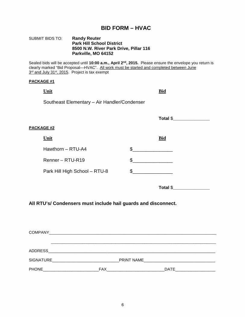
BID FORM – HVAC
SUBMIT BIDS TO: Randy Reuter Park Hill School District 8500 N.W. River Park Drive, Pillar 116 Parkville, MO 64152 Sealed bids will be accepted until 10:00 a.m., April 2nd, 2015. Please ensure the envelope you return is clearly marked “Bid Proposal—HVAC”. All work must be started and completed between June 3rd and July 31st, 2015. Project is tax exempt PACKAGE #1
Unit Bid Southeast Elementary – Air Handler/Condenser
Total $_______________ PACKAGE #2
Unit Bid Hawthorn – RTU-A4 $_______________ Renner – RTU-R19 $_______________ Park Hill High School – RTU-8 $_______________
Total $_______________
All RTU’s/ Condensers must include hail guards and disconnect. COMPANY___________________________________________________________________________ __________________________________________________________________________ ADDRESS___________________________________________________________________________ SIGNATURE______________________________PRINT NAME________________________________ PHONE_________________________FAX__________________________DATE__________________
6

SECTION 26 29 23 - VARIABLE-FREQUENCY MOTOR CONTROLLERS
PART 1 - GENERAL
1.1 SUMMARY
A. This Section includes solid-state, pulse-width modulated (PWM), variable frequency controllers (VFCs) for speed control of three-phase, squirrel-cage induction motors.
1.2 SUBMITTALS
A. Product Data: For each type of VFC.
B. Shop Drawings: For each VFC. 1. Include wiring diagrams.
C. Field quality-control test reports.
D. Operation and maintenance data.
E. Load-current and overload-relay heater list.
F. Load-current and list of settings of adjustable overload relays.
1.3 QUALITY ASSURANCE
A. Electrical Components, Devices, and Accessories: Listed and labeled as defined in NFPA 70, Article 100.
B. Comply with NFPA 70.
C. Product Selection for Restricted Space: Drawings indicate maximum dimensions for VFCs, minimum clearances between VFCs, and adjacent surfaces and other items. Comply with indicated maximum dimensions and clearances.
1.4 PROJECT CONDITIONS
A. Environmental Limitations: Rate equipment for continuous operation, capable of driving full load without derating, under the following conditions, unless otherwise indicated: 1. Ambient Temperature: 0 to 40 deg C. 2. Humidity: Less than 90 percent (noncondensing). 3. Altitude: Not exceeding 3300 feet.
1.5 COORDINATION
A. Coordinate features of VFCs, installed units, and accessory devices with pilot devices and control circuits to which they connect.
PART 2 - PRODUCTS
2.1 MANUFACTURERS
A. Manufacturers: Subject to compliance with requirements, all VFD’s shall be supplied by the same manufacturer with the same features including warranty and start-up. Service to be provided by the same organization. Provide products by one of the following: 1. ABB Power Distribution, Inc.; ABB Control, Inc. Subsidiary. 2. Eaton Corporation; Cutler-Hammer Products.
7

2.2 VARIABLE FREQUENCY CONTROLLERS
A. Description: NEMA ICS 2, IGBT, PWM, VFC; listed and labeled as a complete unit and arranged to provide variable speed of an NEMA MG 1, Design B, 3-phase induction motor by adjusting output voltage and frequency. 1. Provide unit suitable for operation of premium-efficiency motor as defined by NEMA MG 1.
B. Design and Rating: Match load type such as fans, blowers, and pumps; and type of connection used between motor and load such as direct or through a power-transmission connection.
C. Output Rating: 3-phase; 6 to 60 Hz, with voltage proportional to frequency throughout voltage range.
D. Unit Operating Requirements: 1. Input frequency tolerance of 50/60 Hz, plus or minus 6 percent. 2. Minimum Efficiency: 96 percent at 60 Hz, full load. 3. Minimum Displacement Primary-Side Power Factor: 96 percent. 4. Overload Capability: 1.1 times the base load current for 60 seconds; 2.0 times the base load
current for 3 seconds. 5. Starting Torque: 100 percent of rated torque or as indicated. 6. Speed Regulation: Plus or minus 1 percent.
E. Isolated control interface to allow controller to follow control signal over an 11:1 speed range. 1. Electrical Signal: 4 to 20 mA at 24 V. 2. Pneumatic Signal: 3 to 15 psig (20 to 104 kPa).
F. Internal Adjustability Capabilities: 1. Minimum Speed: 5 to 25 percent of maximum rpm. 2. Maximum Speed: 80 to 100 percent of maximum rpm. 3. Acceleration: 2 to a minimum of 22 seconds. 4. Deceleration: 2 to a minimum of 22 seconds. 5. Current Limit: 50 to a minimum of 110 percent of maximum rating.
G. Self-Protection and Reliability Features: 1. Input transient protection by means of surge suppressors. 2. Under- and overvoltage trips; inverter overtemperature, overload, and overcurrent trips. 3. Motor Overload Relay: Adjustable and capable of NEMA ICS 2, Class 10 performance. 4. Notch filter to prevent operation of the controller-motor-load combination at a natural
frequency of the combination. 5. Instantaneous line-to-line and line-to-ground overcurrent trips. 6. Loss-of-phase protection. 7. Reverse-phase protection. 8. Short-circuit protection. 9. Motor overtemperature fault.
H. Automatic Reset/Restart: Attempts three restarts after controller fault or on return of power after an interruption and before shutting down for manual reset or fault correction. Bidirectional autospeed search shall be capable of starting into rotating loads spinning in either direction and returning motor to set speed in proper direction, without damage to controller, motor, or load.
I. Power-Interruption Protection: To prevent motor from re-energizing after a power interruption until motor has stopped.
J. Torque Boost: Automatically varies starting and continuous torque to at least 1.5 times the minimum torque to ensure high-starting torque and increased torque at slow speeds.
K. Motor Temperature Compensation at Slow Speeds: Adjustable current fall-back based on output frequency for temperature protection of self-cooled, fan-ventilated motors at slow speeds.
L. Status Lights: Door-mounted LED indicators shall indicate the following conditions:
8
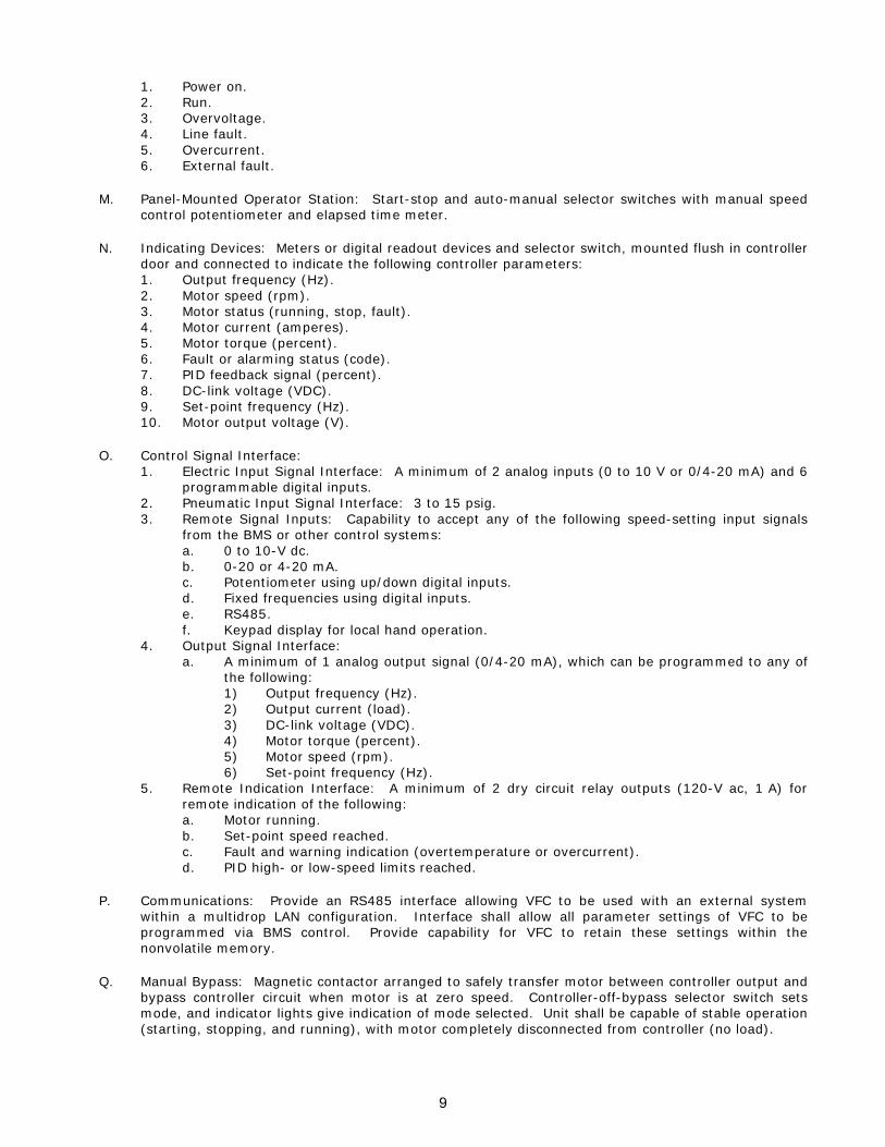
1. Power on. 2. Run. 3. Overvoltage. 4. Line fault. 5. Overcurrent. 6. External fault.
M. Panel-Mounted Operator Station: Start-stop and auto-manual selector switches with manual speed control potentiometer and elapsed time meter.
N. Indicating Devices: Meters or digital readout devices and selector switch, mounted flush in controller door and connected to indicate the following controller parameters: 1. Output frequency (Hz). 2. Motor speed (rpm). 3. Motor status (running, stop, fault). 4. Motor current (amperes). 5. Motor torque (percent). 6. Fault or alarming status (code). 7. PID feedback signal (percent). 8. DC-link voltage (VDC). 9. Set-point frequency (Hz). 10. Motor output voltage (V).
O. Control Signal Interface: 1. Electric Input Signal Interface: A minimum of 2 analog inputs (0 to 10 V or 0/4-20 mA) and 6
programmable digital inputs. 2. Pneumatic Input Signal Interface: 3 to 15 psig. 3. Remote Signal Inputs: Capability to accept any of the following speed-setting input signals
from the BMS or other control systems: a. 0 to 10-V dc. b. 0-20 or 4-20 mA. c. Potentiometer using up/down digital inputs. d. Fixed frequencies using digital inputs. e. RS485. f. Keypad display for local hand operation.
4. Output Signal Interface: a. A minimum of 1 analog output signal (0/4-20 mA), which can be programmed to any of
the following: 1) Output frequency (Hz). 2) Output current (load). 3) DC-link voltage (VDC). 4) Motor torque (percent). 5) Motor speed (rpm). 6) Set-point frequency (Hz).
5. Remote Indication Interface: A minimum of 2 dry circuit relay outputs (120-V ac, 1 A) for remote indication of the following: a. Motor running. b. Set-point speed reached. c. Fault and warning indication (overtemperature or overcurrent). d. PID high- or low-speed limits reached.
P. Communications: Provide an RS485 interface allowing VFC to be used with an external system within a multidrop LAN configuration. Interface shall allow all parameter settings of VFC to be programmed via BMS control. Provide capability for VFC to retain these settings within the nonvolatile memory.
Q. Manual Bypass: Magnetic contactor arranged to safely transfer motor between controller output and bypass controller circuit when motor is at zero speed. Controller-off-bypass selector switch sets mode, and indicator lights give indication of mode selected. Unit shall be capable of stable operation (starting, stopping, and running), with motor completely disconnected from controller (no load).
9

R. Bypass Controller: NEMA ICS 2, full-voltage, nonreversing enclosed controller with across-the-line starting capability in manual-bypass mode. Provide motor overload protection under both modes of operation with control logic that allows common start-stop capability in either mode.
S. Integral Disconnecting Means: NEMA AB 1, instantaneous-trip circuit breaker with lockable handle.
T. Isolating Switch: Non-load-break switch arranged to isolate VFC and permit safe troubleshooting and testing, both energized and de-energized, while motor is operating in bypass mode.
U. Remote Indicating Circuit Terminals: Mode selection, controller status, and controller fault.
2.3 ACCESSORIES
A. Devices shall be factory installed in controller enclosure, unless otherwise indicated.
B. Push-Button Stations, Pilot Lights, and Selector Switches: NEMA ICS 2, heavy-duty type.
C. Stop and Lockout Push-Button Station: Momentary-break, push-button station with a factory-applied hasp arranged so padlock can be used to lock push button in depressed position with control circuit open.
D. Control Relays: Auxiliary and adjustable time-delay relays.
E. Standard Displays: 1. Output frequency (Hz). 2. Set-point frequency (Hz). 3. Motor current (amperes). 4. DC-link voltage (VDC). 5. Motor torque (percent). 6. Motor speed (rpm). 7. Motor output voltage (V).
2.4 FACTORY FINISHES
A. Finish: Manufacturer's standard paint applied to VFCs before shipping.
2.5 WARRANTY
A. A standard 1 year material and labor warranty shall be provided covering all materials supplied and installed.
PART 3 - EXECUTION
3.1 APPLICATIONS
A. Select features of each VFC to coordinate with ratings and characteristics of supply circuit and motor; required control sequence; and duty cycle of motor, controller, and load.
B. Select horsepower rating of controllers to suit motor controlled.
3.2 INSTALLATION
A. Install VFCs on concrete bases.
B. Comply with mounting and anchoring requirements specified in Division 26 Section "Hangers and Supports for Electrical Systems."
10
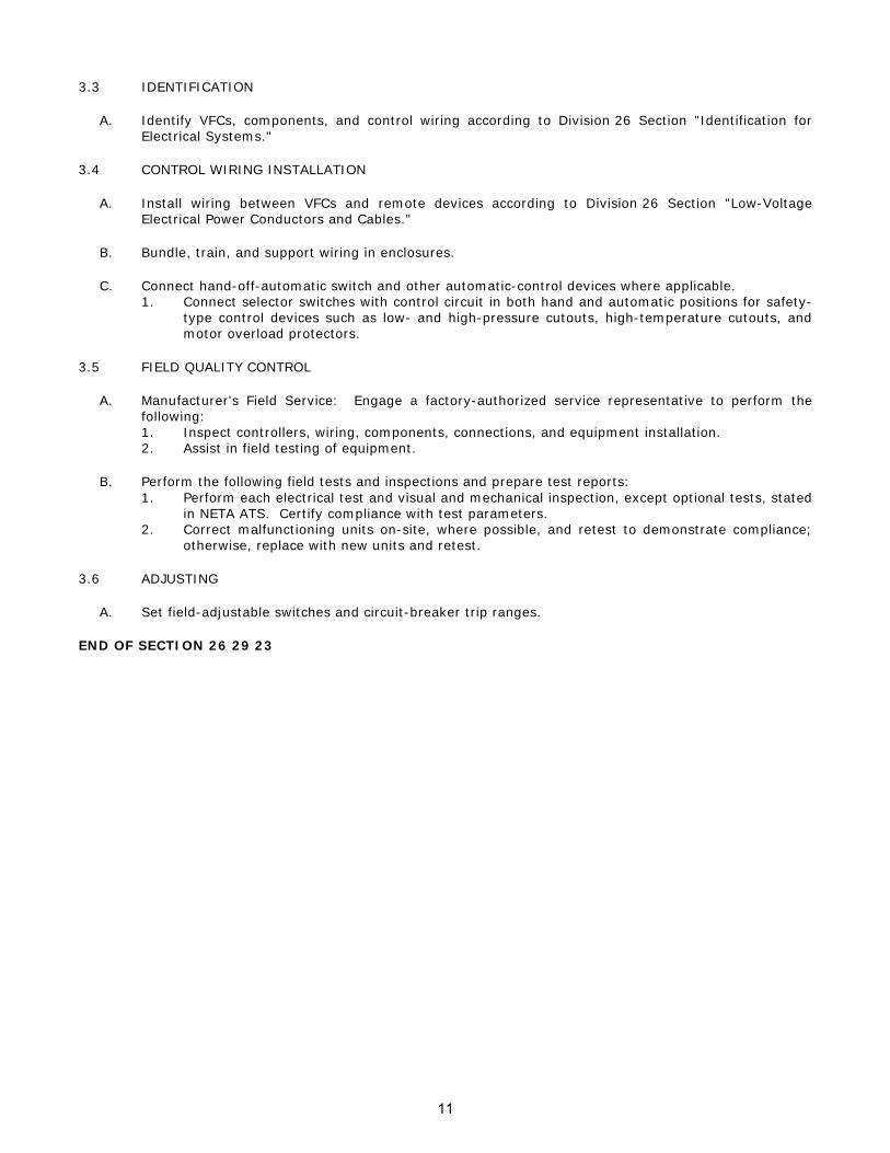
3.3 IDENTIFICATION
A. Identify VFCs, components, and control wiring according to Division 26 Section "Identification for Electrical Systems."
3.4 CONTROL WIRING INSTALLATION
A. Install wiring between VFCs and remote devices according to Division 26 Section "Low-Voltage Electrical Power Conductors and Cables."
B. Bundle, train, and support wiring in enclosures.
C. Connect hand-off-automatic switch and other automatic-control devices where applicable. 1. Connect selector switches with control circuit in both hand and automatic positions for safety-
type control devices such as low- and high-pressure cutouts, high-temperature cutouts, and motor overload protectors.
3.5 FIELD QUALITY CONTROL
A. Manufacturer's Field Service: Engage a factory-authorized service representative to perform the following: 1. Inspect controllers, wiring, components, connections, and equipment installation. 2. Assist in field testing of equipment.
B. Perform the following field tests and inspections and prepare test reports: 1. Perform each electrical test and visual and mechanical inspection, except optional tests, stated
in NETA ATS. Certify compliance with test parameters. 2. Correct malfunctioning units on-site, where possible, and retest to demonstrate compliance;
otherwise, replace with new units and retest.
3.6 ADJUSTING
A. Set field-adjustable switches and circuit-breaker trip ranges.
END OF SECTION 26 29 23
11
SECTION 23 73 13 – INDOOR, MULTIZONE, CENTRAL-STATION AIR-HANDLING UNITS
PART 1 - GENERAL
1.1 RELATED DOCUMENTS
A. Drawings and general provisions of the Contract, including General and Supplementary Conditions and Division 01 Specification Sections, apply to this Section.
1.2 SUMMARY
A. Section Includes: 1. Multi-Zone, constant volume air handling units.
1.3 ACTION SUBMITTALS
A. Product Data: For each air-handling unit indicated. 1. Unit dimensions and weight. 2. Cabinet material, metal thickness, finishes, insulation, and accessories. 3. Fans:
a. Certified fan-performance curves with system operating conditions indicated. b. Certified fan-sound power ratings. c. Fan construction and accessories. d. Motor ratings, electrical characteristics, and motor accessories.
4. Certified coil-performance ratings with system operating conditions indicated. 5. Dampers, including housings, linkages, and operators. 6. Filters with performance characteristics.
1.4 INFORMATIONAL SUBMITTALS
A. Coordination Drawings: Floor plans and other details, drawn to scale, on which the following items are shown and coordinated with each other, using input from installers of the items involved: 1. Mechanical-room layout and relationships between components and adjacent structural and
mechanical elements. 2. Support location, type, and weight. 3. Field measurements.
B. Source quality-control reports.
C. Field quality-control reports.
1.5 CLOSEOUT SUBMITTALS
A. Operation and Maintenance Data: For air-handling units to include in emergency, operation, and maintenance manuals.
1.6 MAINTENANCE MATERIAL SUBMITTALS
A. Furnish extra materials that match products installed and that are packaged with protective covering for storage and identified with labels describing contents. 1. Filters: 2 set(s) for each air-handling unit.
1.7 QUALITY ASSURANCE
A. Electrical Components, Devices, and Accessories: Listed and labeled as defined in NFPA 70, by a qualified testing agency, and marked for intended location and application.
12
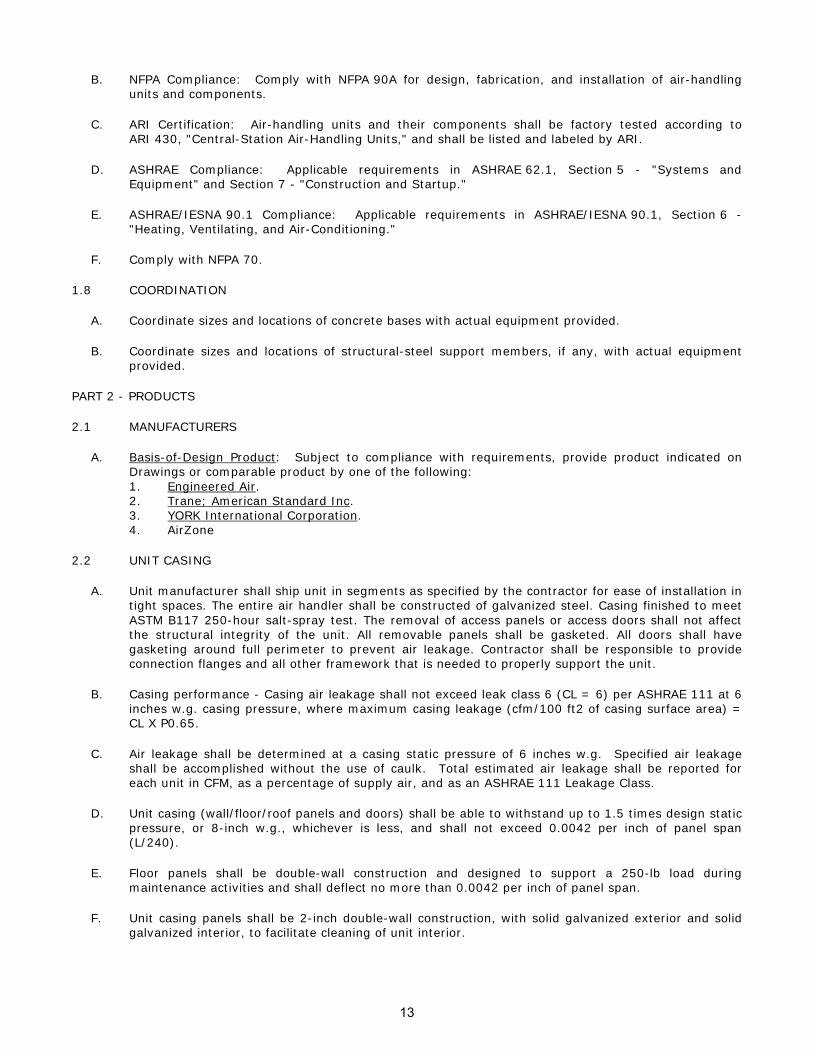
B. NFPA Compliance: Comply with NFPA 90A for design, fabrication, and installation of air-handling units and components.
C. ARI Certification: Air-handling units and their components shall be factory tested according to ARI 430, "Central-Station Air-Handling Units," and shall be listed and labeled by ARI.
D. ASHRAE Compliance: Applicable requirements in ASHRAE 62.1, Section 5 - "Systems and Equipment" and Section 7 - "Construction and Startup."
E. ASHRAE/IESNA 90.1 Compliance: Applicable requirements in ASHRAE/IESNA 90.1, Section 6 - "Heating, Ventilating, and Air-Conditioning."
F. Comply with NFPA 70.
1.8 COORDINATION
A. Coordinate sizes and locations of concrete bases with actual equipment provided.
B. Coordinate sizes and locations of structural-steel support members, if any, with actual equipment provided.
PART 2 - PRODUCTS
2.1 MANUFACTURERS
A. Basis-of-Design Product: Subject to compliance with requirements, provide product indicated on Drawings or comparable product by one of the following: 1. Engineered Air. 2. Trane; American Standard Inc. 3. YORK International Corporation. 4. AirZone
2.2 UNIT CASING
A. Unit manufacturer shall ship unit in segments as specified by the contractor for ease of installation in tight spaces. The entire air handler shall be constructed of galvanized steel. Casing finished to meet ASTM B117 250-hour salt-spray test. The removal of access panels or access doors shall not affect the structural integrity of the unit. All removable panels shall be gasketed. All doors shall have gasketing around full perimeter to prevent air leakage. Contractor shall be responsible to provide connection flanges and all other framework that is needed to properly support the unit.
B. Casing performance - Casing air leakage shall not exceed leak class 6 (CL = 6) per ASHRAE 111 at 6 inches w.g. casing pressure, where maximum casing leakage (cfm/100 ft2 of casing surface area) = CL X P0.65.
C. Air leakage shall be determined at a casing static pressure of 6 inches w.g. Specified air leakage shall be accomplished without the use of caulk. Total estimated air leakage shall be reported for each unit in CFM, as a percentage of supply air, and as an ASHRAE 111 Leakage Class.
D. Unit casing (wall/floor/roof panels and doors) shall be able to withstand up to 1.5 times design static pressure, or 8-inch w.g., whichever is less, and shall not exceed 0.0042 per inch of panel span (L/240).
E. Floor panels shall be double-wall construction and designed to support a 250-lb load during maintenance activities and shall deflect no more than 0.0042 per inch of panel span.
F. Unit casing panels shall be 2-inch double-wall construction, with solid galvanized exterior and solid galvanized interior, to facilitate cleaning of unit interior.
13

G. Unit casing panels (roof, walls, floor) and doors shall be provided with a minimum thermal resistance (R-value) of 13 Hr*Ft2*°F/BTU.
H. Unit casing panels (roof, walls, floor) and external structural frame members shall be completely insulated filling the entire panel cavity in all directions so that no voids exist. Panel insulation shall comply with NFPA 90A.
I. Casing panel inner liners must not extend to the exterior of the unit or contact the exterior frame. A mid-span, no-through-metal, internal thermal break shall be provided for all unit casing panels.
J. Access DOORS shall be provided in all sections to allow easy access to filters, drain pan, coil(s), motor, drive components and bearings for cleaning, inspection, and maintenance.
K. Access panels and doors shall be fully removable without the use of specialized tools to allow complete access of interior surfaces.
L. Access doors shall be 2-inch double-wall construction. Interior and exterior shall be of the same construction as the interior and exterior wall panels.
M. Gasketing shall be provided around the full perimeter of the doors to prevent air leakage.
N. Door hardware shall be surface-mounted to prevent through-cabinet penetrations that could likely weaken the casing leakage and thermal performance.
O. Handle hardware shall be designed to prevent unintended closure.
P. Access doors shall be hinged and removable without the use of specialized tools to allow.
Q. Hinges shall be interchangeable with the door handle hardware to allow for alternating door swing in the field to minimize access interference.
R. Door handle hardware shall be adjustable and visually indicate locking position of door latch external to the section.
S. All doors shall be a 60-inch high when sufficient unit height is available, or the maximum height allowed by the unit height.
T. A single door handle shall be provided for each door linking multiple latching points necessary to maintain the specified air leakage integrity of the unit.
U. A shatterproof window shall be provided in access doors where indicated on the plans.
2.3 MARINE LIGHTS
A. Marine lights shall be provided throughout AHUs as indicated on the schedule and plans. Lights shall be instant-on, light-emitting diode (LED) type to minimize amperage draw and shall produce lumens equivalent to a minimum 75W incandescent bulb (1200 lumens). LED lighting shall provide instant-on, white light and have a minimum 50,000 hr life.
B. Light fixture shall be weather-resistant, enclosed and gasketed to prevent water and dust intrusion.
C. Fixtures shall be designed for flexible positioning during maintenance and service activities for best possible location providing full light on work surface of interest and not being blocked by technician.
D. All lights on a unit shall be wired in the factory to a single on-off switch.
E. Installing contractor shall be responsible for providing 115V supply to the factory-mounted marine light circuit
14

2.4 CONDENSATE DRAIN PANS:
A. Fabricated with two percent slope in at least two planes to collect condensate from cooling coils (including coil piping connections, coil headers, and return bends) and from humidifiers and to direct water toward drain connection. 1. Length: Extend drain pan downstream from leaving face ASHRAE 62.1 2. Depth: A minimum of 2 inches
B. Double-wall, stainless-steel sheet.
C. Drain Connection: Located at lowest point of pan and sized to prevent overflow. Terminate with threaded nipple on one end of pan. 1. Minimum Connection Size: NPS 2
D. Units with stacked coils shall have an intermediate drain pan to collect condensate from top coil.
2.5 AIR-HANDLING-UNIT MOUNTING FRAME
A. Formed galvanized-steel channel or structural channel supports, designed for low deflection, welded with integral lifting lugs.
2.6 FAN, DRIVE, AND MOTOR SECTION
A. Fan Assemblies: Statically and dynamically balanced and designed for continuous operation at maximum-rated fan speed and motor horsepower. 1. Shafts: Designed for continuous operation at maximum-rated fan speed and motor
horsepower, and with field-adjustable alignment. a. Turned, ground, and polished hot-rolled steel with keyway. Ship with a protective
coating of lubricating oil. b. Designed to operate at no more than 70 percent of first critical speed at top of fan's
speed range.
B. Fan sections shall have a minimum of one hinged and latched access door located on the drive side of the unit to allow inspection and maintenance of the fan, and motor components.
C. Provide fans as follows 1. Supply Fans > 5,000 cfm -- Dual Direct Drive Plenum Class I or II
D. Fans, shall be mounted on isolation bases. Internally-mounted motor shall be on the same isolation base. Fan and motor shall be internally isolated with spring isolators. Unit sizes up to a nominal 4,000 CFM shall have 1-inch spring isolation. Units with nominal CFM's higher than 4,000 shall have 2-inch springs. A flexible connection (e.g. canvas duct) shall be installed between fan and unit casing to ensure complete isolation. Flexible connection shall comply with NFPA 90A and UL 181 requirements. If fans and motors are not internally isolated, then the entire unit shall be externally isolated from the building, including supply and return duct work, piping, and electrical connections. External isolation shall be furnished by the installing contractor in order to avoid transmission of noise and vibration through the ductwork and building structure.
E. Fan airflow measurement systems shall be provided as indicated on the schedule and drawings to measure fan airflow directly or to measure differential pressure that can be used to calculate airflow. The accuracy of the devices shall be no worse than +/- 5 percent when operating within stable fan operating conditions. Devices shall not affect the submitted fan performance and acoustical levels. Devices that obstruct the fan inlet or outlet shall not be acceptable. Devices shall be connected to transducers with selectable 4-20 mA or 2-10 VDC output. Signal shall be proportional to air velocity.
F. Motors and Drives: 1. All motors shall be factory-installed and run tested. 2. Motors shall meet or exceed all NEMA Standards Publication MG 1 - 2006 requirements and
comply with NEMA Premium efficiency levels when applicable. Motors shall comply with applicable requirements of NEC and shall be UL Listed.
15

3. Fan Motors shall be heavy duty, open drip-proof operable at 460 volts, 60Hz, 3-phase. If applicable, motor efficiency shall meet or exceed NEMA Premium efficiencies.
4. Direct driven fans shall use 2-pole (3600 rpm), 4-pole (1800 rpm) or 6-pole (1200 rpm) motors, NEMA Design B, with Class B insulation capable to operate continuously at 104 deg F (40 deg C) without tripping overloads.
5. Motors shall have a +/- 10 percent voltage utilization range to protect against voltage variation.
6. Manufacturer shall provide for each fan a nameplate with the following information to assist air balance contractor in start up and service personnel in maintenance: a. Fan and motor sheave part number b. Fan and motor bushing part number c. Number of belts and belt part numbers d. Fan design RPM and motor HP e. Belt tension and deflection f. Center distance between shafts
G. Variable Frequency Controllers: - FACTORY MOUNTED AND WIRED 1. Description: NEMA ICS 2, IGBT, PWM, VFC; listed and labeled as a complete unit and
arranged to provide variable speed of an NEMA MG 1, Design B, 3-phase induction motor by adjusting output voltage and frequency.
2. Output Rating: 3-phase; 6 to 60 Hz, with voltage proportional to frequency throughout voltage range
3. Unit Operating Requirements: a. Input ac voltage tolerance of 208 V, plus or minus 5 percent. b. Input frequency tolerance of 03/11 Hz, plus or minus 6 percent. c. Minimum Efficiency: 96 percent at 60 Hz, full load. d. Minimum Displacement Primary-Side Power Factor: 96 percent. e. Overload Capability: 1.1 times the base load current for 60 seconds; 2.0 times the base
load current for 3 seconds. f. Starting Torque: 100 percent of rated torque or as indicated. g. Speed Regulation: Plus or minus 1 percent.
4. Isolated control interface to allow controller to follow control signal over an 11:1 speed range. 5. Internal Adjustability Capabilities:
a. Minimum Speed: 5 to 25 percent of maximum rpm. b. Maximum Speed: 80 to 100 percent of maximum rpm. c. Acceleration: 2 to a minimum of 22 seconds. d. Deceleration: 2 to a minimum of 22 seconds. e. Current Limit: 50 to a minimum of 110 percent of maximum rating.
6. Self-Protection and Reliability Features: a. Input transient protection by means of surge suppressors. b. Undervoltage and overvoltage trips; inverter overtemperature, overload, and
overcurrent trips. c. Adjustable motor overload relays capable of NEMA ICS 2, Class 10 performance. d. Notch filter to prevent operation of the controller-motor-load combination at a natural
frequency of the combination. e. Instantaneous line-to-line and line-to-ground overcurrent trips. f. Loss-of-phase protection. g. Reverse-phase protection. h. Short-circuit protection. i. Motor overtemperature fault.
7. Automatic Reset/Restart: Attempts three restarts after controller fault or on return of power after an interruption and before shutting down for manual reset or fault correction. Bidirectional autospeed search shall be capable of starting into rotating loads spinning in either direction and returning motor to set speed in proper direction, without damage to controller, motor, or load.
8. Power-Interruption Protection: To prevent motor from re-energizing after a power interruption until motor has stopped.
9. Torque Boost: Automatically varies starting and continuous torque to at least 1.5 times the minimum torque to ensure high-starting torque and increased torque at slow speeds.
16

10. Motor Temperature Compensation at Slow Speeds: Adjustable current fall-back based on output frequency for temperature protection of self-cooled, fan-ventilated motors at slow speeds.
11. Door-mounted LED status lights shall indicate the following conditions: a. Power on. b. Run. c. Overvoltage. d. Line fault. e. Overcurrent. f. External fault.
12. Panel-Mounted Operator Station: Start-stop and auto-manual selector switches with manual-speed-control potentiometer and elapsed time meter.
13. Meters or digital readout devices and selector switch, mounted flush in controller door and connected to indicate the following controller parameters: a. Output frequency (Hertz). b. Motor speed (rpm). c. Motor status (running, stop, fault). d. Motor current (amperes). e. Motor torque (percent). f. Fault or alarming status (code). g. Proportional-integral-derivative (PID) feedback signal (percent). h. DC-link voltage (volts direct current). i. Set-point frequency (Hertz). j. Motor output voltage (volts).
14. Control Signal Interface: a. Electric Input Signal Interface: A minimum of 2 analog inputs (0 to 10 V or 0/4-20 mA)
and 6 programmable digital inputs. b. Remote signal inputs capable of accepting any of the following speed-setting input
signals from the control system: 1) 0 to 10-V dc. 2) 0-20 or 4-20 mA. 3) Potentiometer using up/down digital inputs. 4) Fixed frequencies using digital inputs. 5) RS485. 6) Keypad display for local hand operation.
c. Output signal interface with a minimum of 1 analog output signal (0/4-20 mA), which can be programmed to any of the following: 1) Output frequency (Hertz). 2) Output current (load). 3) DC-link voltage (volts direct current). 4) Motor torque (percent). 5) Motor speed (rpm). 6) Set-point frequency (Hertz).
d. Remote indication interface with a minimum of 2 dry circuit relay outputs (120-V ac, 1 A) for remote indication of the following: 1) Motor running. 2) Set-point speed reached. 3) Fault and warning indication (overtemperature or overcurrent). 4) High- or low-speed limits reached.
15. Communications: RS485 interface allows VFC to be used with an external system within a multidrop LAN configuration. Interface shall allow all parameter settings of VFC to be programmed via BMS control. Provide capability for VFC to retain these settings within the nonvolatile memory.
16. Integral Disconnecting Means: NEMA AB 1, instantaneous-trip circuit breaker with lockable handle.
17. Accessories: a. Devices shall be factory installed in controller enclosure unless otherwise indicated. b. Push-Button Stations, Pilot Lights, and Selector Switches: NEMA ICS 2, heavy-duty
type. c. Standard Displays:
1) Output frequency (Hertz).
17

2) Set-point frequency (Hertz). 3) Motor current (amperes). 4) DC-link voltage (volts direct current). 5) Motor torque (percent). 6) Motor speed (rpm). 7) Motor output voltage (volts).
2.7 COIL SECTION
A. General Requirements for Coil Sections: 1. Comply with ARI 410. 2. Fabricate coil section to allow removal and replacement of coil for maintenance and to allow
in-place access for service and maintenance of coil(s). 3. For multizone units, provide air deflectors and air baffles to balance airflow across coils. 4. Coils shall not act as structural component of unit.
B. Supply-Air Refrigerant Coil 1. Refrigerant suction and liquid connections shall be clearly labeled on unit exterior. 2. Refrigerant suction and liquid headers shall be constructed of copper tubing. Suction and liquid
connections shall penetrate unit casings to allow for sweat connections to refrigerant lines. 3. Tubes shall be 1/2 inch O.D., minimum .016 inch thick copper. Fins shall be aluminum. 4. Aluminum-plate fin and seamless copper tube in steel casing with equalizing-type vertical
distributor. 5. Polymer strip shall prevent all copper coil from contacting steel coil frame or condensate pan. 6. Coil Split: Interlaced. 7. Condensate Drain Pan: Stainless steel formed with pitch and drain connections complying
with ASHRAE 62.1-2004.
2.8 AIR FILTRATION SECTION
A. General Requirements for Air Filtration Section: 1. Comply with NFPA 90A. 2. Provide minimum arrestance according to ASHRAE 52.1, and a minimum efficiency reporting
value (MERV) according to ASHRAE 52.2. 3. Provide filter holding frames arranged for flat or angular orientation, with access doors on both
sides of unit. Filters shall be removable from one side or lifted out from access plenum.
B. Disposable Panel Filters: 1. Factory-fabricated, viscous-coated, flat-panel type. 2. Thickness: 2 inches 3. Arrestance (ASHRAE 52.1): 80 4. Merv (ASHRAE 52.2): 8 5. Media: Interlaced glass fibers sprayed with nonflammable adhesive 6. Frame: Galvanized steel, with metal grid on outlet side, steel rod grid on inlet side, hinged,
and with pull and retaining handles.
C. Filter Gage: 1. 3-1/2-inch diameter, diaphragm-actuated dial in metal case. 2. Vent valves. 3. Black figures on white background. 4. Front recalibration adjustment. 5. 2 percent of full-scale accuracy. 6. Range: 0- to 0.5-inch wg Accessories: Static-pressure tips with integral compression fittings,
1/4-inch aluminum tubing, and 2- or 3-way vent valves.
2.9 DAMPERS
A. General Requirements for Dampers: Leakage rate, according to AMCA 500, "Laboratory Methods for Testing Dampers for Rating," shall not exceed 2 percent of air quantity at 2000-fpm face velocity through damper and 4-inch wg pressure differential.
18

B. Damper Operators: Comply with requirements in Section 230900 "Instrumentation and Control for HVAC."
C. Outdoor- and Return-Air Dampers: Low-leakage, double-skin, airfoil-blade, galvanized-steel dampers with compressible jamb seals and extruded-vinyl blade edge seals in -blade arrangement with steel operating rods rotating in stainless-steel sleeve bearings mounted in a single galvanized-steel frame, and with operating rods connected with a common linkage. Leakage rate shall not exceed 5 cfm/sq. ft at 1-inch wg and 9 cfm/sq. ft at 4-inch wg
D. Mixing Section: Multiple-blade, air-mixer assembly located immediately downstream of mixing section.
E. Combination Filter and Mixing Section: 1. Cabinet support members shall hold 2-inch thick, pleated, flat, permanent or throwaway
filters. 2. Multiple-blade, air-mixer assembly shall mix air to prevent stratification, located immediately
downstream of mixing box.
2.10 CAPACITIES AND CHARACTERISTICS
A. As shown on drawings.
2.11 SOURCE QUALITY CONTROL
A. Fan Sound-Power Level Ratings: Comply with AMCA 301, "Methods for Calculating Fan Sound Ratings from Laboratory Test Data." Test fans according to AMCA 300, "Reverberant Room Method for Sound Testing of Fans." Fans shall bear AMCA-certified sound ratings seal.
B. Fan Performance Rating: Factory test fan performance for airflow, pressure, power, air density, rotation speed, and efficiency. Rate performance according to AMCA 210, "Laboratory Methods of Testing Fans for Aerodynamic Performance Rating."
C. Water Coils: Factory tested to 300 psig according to ARI 410 and ASHRAE 33.
D. Steam Coils: Factory tested to 300 psig and to 200 psig underwater according to ARI 410 and ASHRAE 33.
E. Refrigerant Coils: Factory tested to 450 psig according to ARI 410 and ASHRAE 33.
2.12 WARRANTY
A. A standard 1 year material and labor warranty shall be provided covering all materials supplied and installed.
PART 3 - EXECUTION
3.1 EXAMINATION
A. Examine areas and conditions, with Installer present, for compliance with requirements for installation tolerances and other conditions affecting performance of the Work.
B. Examine casing insulation materials and filter media before air-handling unit installation. Reject insulation materials and filter media that are wet, moisture damaged, or mold damaged.
C. Examine roughing-in for steam, hydronic, and condensate drainage piping systems and electrical services to verify actual locations of connections before installation.
D. Proceed with installation only after unsatisfactory conditions have been corrected.
19

3.2 INSTALLATION
A. Equipment Mounting: Install air-handling units on concrete bases. Secure units to anchor bolts installed in concrete bases. Comply with requirements for concrete bases specified in Section 033000 "Cast-in-Place Concrete. Comply with requirements for vibration isolation devices specified in Section 230548 "Vibration and Seismic Controls for HVAC Piping and Equipment." 1. Install dowel rods to connect concrete base to concrete floor. Unless otherwise indicated,
install dowel rods around the full perimeter of concrete base. 2. Install epoxy-coated anchor bolts that extend through concrete base and anchor into
structural concrete floor. 3. Place and secure anchorage devices. Use setting drawings, templates, diagrams, instructions,
and directions furnished with items to be embedded. 4. Install anchor bolts to elevations required for proper attachment to supported equipment.
B. Arrange installation of units to provide access space around air-handling units for service and maintenance.
C. Do not operate fan system until filters (temporary or permanent) are in place. Replace temporary filters used during construction and testing, with new, clean filters.
D. Install filter-gage, static-pressure taps upstream and downstream of filters. Mount filter gages on outside of filter housing or filter plenum in accessible position. Provide filter gages on filter banks, installed with separate static-pressure taps upstream and downstream of filters.
3.3 CONNECTIONS
A. Comply with requirements for piping specified in other Sections. Drawings indicate general arrangement of piping, fittings, and specialties.
B. Install piping adjacent to air-handling unit to allow service and maintenance.
C. Connect piping to air-handling units mounted on vibration isolators with flexible connectors.
D. Connect condensate drain pans using NPS 1-1/4, ASTM B 88, Type M copper tubing. Extend to nearest equipment or floor drain. Construct deep trap at connection to drain pan and install cleanouts at changes in direction.
E. Hot-Water Piping: Comply with applicable requirements in Section 232113 "Hydronic Piping." Install shutoff valve and union or flange at each coil supply connection. Install balancing valve and union or flange at each coil return connection.
F. Steam and Condensate Piping: Comply with applicable requirements in Section 232213 "Steam and Condensate Heating Piping." Install shutoff valve at steam supply connections, float and thermostatic trap, and union or flange at each coil return connection. Install gate valve and inlet strainer at supply connection of dry steam humidifiers, and inverted bucket steam trap to condensate return connection.
G. Refrigerant Piping: Comply with applicable requirements in Section 232300 "Refrigerant Piping." Install shutoff valve and union or flange at each supply and return connection.
H. Connect duct to air-handling units with flexible connections. Comply with requirements in Section 233300 "Air Duct Accessories."
3.4 FIELD QUALITY CONTROL
A. Manufacturer's Field Service: Engage a factory-authorized service representative to inspect, test, and adjust components, assemblies, and equipment installations, including connections.
B. Perform tests and inspections.
20

1. Manufacturer's Field Service: Engage a factory-authorized service representative to inspect components, assemblies, and equipment installations, including connections, and to assist in testing.
C. Tests and Inspections: 1. Leak Test: After installation, fill water and steam coils with water, and test coils and
connections for leaks. 2. Charge refrigerant coils with refrigerant and test for leaks. 3. Fan Operational Test: After electrical circuitry has been energized, start units to confirm
proper motor rotation and unit operation. 4. Automatic-Roll-Filter Operational Test: Operate filters to demonstrate compliance with
requirements. Test for leakage of unfiltered air while system is operating. 5. Test and adjust controls and safeties. Replace damaged and malfunctioning controls and
equipment.
D. Air-handling unit or components will be considered defective if unit or components do not pass tests and inspections.
E. Prepare test and inspection reports.
3.5 STARTUP SERVICE
A. Engage a factory-authorized service representative to perform startup service. 1. Complete installation and startup checks according to manufacturer's written instructions. 2. Verify that shipping, blocking, and bracing are removed. 3. Verify that unit is secure on mountings and supporting devices and that connections to piping,
ducts, and electrical systems are complete. Verify that proper thermal-overload protection is installed in motors, controllers, and switches.
4. Verify proper motor rotation direction, free fan wheel rotation, and smooth bearing operations. Reconnect fan drive system, align belts, and install belt guards.
5. Verify that bearings, pulleys, belts, and other moving parts are lubricated with factory-recommended lubricants.
6. Verify that face-and-bypass dampers provide full face flow. 7. Verify that outdoor- and return-air mixing dampers open and close, and maintain minimum
outdoor-air setting. 8. Comb coil fins for parallel orientation. 9. Verify that proper thermal-overload protection is installed for electric coils. 10. Install new, clean filters. 11. Verify that manual and automatic volume control and fire and smoke dampers in connected
duct systems are in fully open position.
B. Starting procedures for air-handling units include the following: 1. Energize motor; verify proper operation of motor, drive system, and fan wheel. Adjust fan to
indicated rpm. Replace fan and motor pulleys as required to achieve design conditions. 2. Measure and record motor electrical values for voltage and amperage. 3. Manually operate dampers from fully closed to fully open position and record fan performance.
3.6 ADJUSTING
A. Adjust damper linkages for proper damper operation.
B. Comply with requirements in Section 230593 "Testing, Adjusting, and Balancing for HVAC" for air-handling system testing, adjusting, and balancing.
3.7 CLEANING
A. After completing system installation and testing, adjusting, and balancing air-handling unit and air-distribution systems and after completing startup service, clean air-handling units internally to remove foreign material and construction dirt and dust. Clean fan wheels, cabinets, dampers, coils, and filter housings, and install new, clean filters.
21

3.8 DEMONSTRATION
A. Engage a factory-authorized service representative to train Owner's maintenance personnel to adjust, operate, and maintain air-handling units.
END OF SECTION 23 73 13
22

SECTION 23 63 13 - AIR-COOLED REFRIGERANT CONDENSING UNITS
PART 1 - GENERAL
1.1 RELATED DOCUMENTS
A. Drawings and general provisions of the Contract, including General and Supplementary Conditions and Division 01 Specification Sections, apply to this Section.
1.2 SUMMARY
A. Section includes packaged, air-cooled refrigerant condensers for outdoor installation.
1.3 ACTION SUBMITTALS
A. Product Data: For each air-cooled refrigerant condenser. Include rated capacities, operating characteristics, furnished specialties, and accessories. Include equipment dimensions, weights and structural loads, required clearances, method of field assembly, components, and location and size of each field connection.
B. Shop Drawings: For air-cooled refrigerant condensers. Include plans, elevations, sections, details, and attachments to other work. 1. Detail equipment assemblies and indicate dimensions, weights, loads, required clearances,
method of field assembly, components, and location and size of each field connection. 2. Wiring Diagrams: For power, signal, and control wiring.
C. Delegated-Design Submittal: For air-cooled refrigerant condensing units indicated to comply with performance requirements and design criteria, including analysis data signed and sealed by the qualified professional engineer responsible for their preparation. 1. Vibration Isolation Base Details: Detail fabrication including anchorages and attachments to
structure and to supported equipment. Include adjustable motor bases, rails, and frames for equipment mounting.
2. Design Calculations: Calculate requirements for selecting vibration isolators and for designing vibration isolation bases.
1.4 INFORMATIONAL SUBMITTALS
A. Coordination Drawings: Plans, drawn to scale, on which the following items are shown and coordinated with each other, based on input from installers of the items involved: 1. Structural members to which air-cooled refrigerant condensers will be attached. 2. Liquid and vapor pipe sizes. 3. Refrigerant specialties. 4. Piping including connections, oil traps, and double risers. 5. Evaporators.
B. Field quality-control reports.
1.5 CLOSEOUT SUBMITTALS
A. Operation and Maintenance Data: For air-cooled refrigerant condensers to include in emergency, operation, and maintenance manuals.
1.6 QUALITY ASSURANCE
A. Electrical Components, Devices, and Accessories: Listed and labeled as defined in NFPA 70, by a qualified testing agency, and marked for intended location and application.
23

B. Fabricate and label refrigeration system according to ASHRAE 15, "Safety Standard for Refrigeration Systems."
C. ASHRAE/IESNA 90.1 Compliance: Applicable requirements in ASHRAE/IESNA 90.1, Section 6 - "Heating, Ventilating, and Air-Conditioning."
1.7 COORDINATION
A. Coordinate installation of roof curbs, equipment supports, and roof penetrations. These items are specified in Section 077200 "Roof Accessories."
B. Coordinate location of refrigerant piping and electrical rough-ins.
PART 2 - PRODUCTS
2.1 MANUFACTURERS
A. Basis-of-Design Product: Subject to compliance with requirements, provide product indicated on Drawings or comparable product by one of the following: 1. YORK; a Johnson Controls company. 2. Trane; a business of American Standard Companies. 3. Engineered Air
2.2 MANUFACTURED UNITS
A. Description: Factory assembled and tested; consisting of casing, condenser coils, condenser fans and motors, and unit controls.
B. Description: Factory assembled and tested; consisting of compressor, condenser coil, fan, motors, refrigerant reservoir, and operating controls.
C. Compressor: Scroll, hermetically sealed, with rubber vibration isolators. 1. Motor: Single speed, and includes thermal- and current-sensitive overload devices, start
capacitor, relay, and contactor. 2. Two-Speed Compressor: Include manual-reset, high-pressure switch and automatic-reset,
low-pressure switch. 3. Accumulator: Suction tube.
D. Refrigerant: R-410A.
E. Condenser Coil: Factory tested at 425 psig 1. Tube: 5/8-inch-diameter seamless copper 2. Coil Fin: Aluminum. 3. Coating: Thermoplastic vinyl 4. Circuits: See schedule of drawings.
F. Condenser Fans and Drives: Propeller fans with aluminum or galvanized-steel fan blades, for vertical air discharge; directly driven with permanently lubricated ball-bearing motors with integral current- and thermal-overload protection. 1. Weather-proof motors with rain shield and shaft slinger. 2. Extend grease lines to outside of casing.
G. Condenser Fans and Drives: Forward-curved centrifugal fans for vertical air discharge. 1. Fan on steel shaft with self-aligning ball bearings. 2. V-belt drive with minimum of two belts; variable pitch drive pulley. 3. Motor mounted on adjustable slide base.
24

H. Operating and Safety Controls: Include condenser fan motor thermal and overload cutouts; 115-V control transformer, if required; magnetic contactors for condenser fan motors and a nonfused factory-mounted and -wired disconnect switch for single external electrical power connection. 1. Fan Cycling Control: Head pressure switches.
I. Casings: Galvanized or zinc-coated steel treated and finished with manufacturer's standard paint coating, designed for outdoor installation with weather protection for components and controls, and with the following: 1. Removable panels for access to controls, condenser fans, motors, and drives. 2. Stainless-steel fan guards. 3. Lifting eyes. 4. Removable legs, as required for application
2.3 CAPACITIES AND CHARACTERISTICS
A. As shown on drawings.
2.4 MOTORS
A. Comply with NEMA designation, temperature rating, service factor, enclosure type, and efficiency requirements for motors specified in Section 230513 "Common Motor Requirements for HVAC Equipment." 1. Enclosure Type: Totally enclosed, fan cooled. 2. Motor Sizes: Minimum size as indicated. If not indicated, large enough so driven load will not
require motor to operate in service factor range above 1.0. 3. Mount unit-mounted disconnect switches on exterior of unit.
2.5 SOURCE QUALITY CONTROL
A. Verification of Performance: Rate air-cooled refrigerant condensers according to ARI 460.
B. Testing Requirements: Factory test sound-power-level ratings according to ARI 270.
2.6 WARRANTY
A. A 1 year parts and labor warranty shall be provided covering all materials supplied and installed, except the compressor. A 5 year parts and labor warranty shall be provided covering the compressor.
PART 3 - EXECUTION
3.1 EXAMINATION
A. Examine substrates, areas, and conditions, with Installer present, for compliance with requirements for installation tolerances and other conditions affecting performance of air-cooled refrigerant condensers.
B. Examine roughing-in for refrigerant piping systems to verify actual locations of piping connections before equipment installation.
C. Examine walls, floors, and roofs for suitable conditions where air-cooled condensers will be installed.
D. Proceed with installation only after unsatisfactory conditions have been corrected.
3.2 INSTALLATION
A. Install units level and plumb, firmly anchored in locations indicated; maintain manufacturer's recommended clearances.
25

B. Equipment Mounting: Install air-cooled condensing units using restrained spring isolators integral to equipment rails. Comply with requirements for vibration isolation devices specified in Section 230548 "Vibration and Seismic Controls for HVAC Piping and Equipment." 1. Minimum Deflection: 1 inch
C. Maintain manufacturer's recommended clearances for service and maintenance.
D. Loose Components: Install electrical components, devices, and accessories that are not factory mounted.
3.3 CONNECTIONS
A. Piping installation requirements are specified in Section 232113 "Hydronic Piping." Drawings indicate general arrangement of piping, fittings, and specialties.
B. Install piping adjacent to machine to allow service and maintenance.
C. Refrigerant Piping: Provide and connect piping to unit with pressure relief, service valve, filter-dryer, and moisture indicator on each refrigerant-circuit liquid line.
3.4 FIELD QUALITY CONTROL
A. Perform tests and inspections. 1. Manufacturer's Field Service: Engage a factory-authorized service representative to inspect,
test, and adjust components, assemblies, and equipment installations, including connections, and to assist in testing.
B. Tests and Inspections: 1. Perform electrical test and visual and mechanical inspection. 2. Leak Test: Charge system to 150# with nitrogen and verify with owner that charge is held for
minimum 24 hours. Schedule Leak Test with owner 5 working days in advance. 3. Operational Test: After electrical circuitry has been energized, start units to confirm proper
motor rotation and unit operation. Complete manufacturer's starting checklist. 4. Test and adjust controls and safeties. Replace damaged and malfunctioning controls and
equipment. 5. Verify proper airflow over coils.
C. Verify that vibration isolation and flexible connections properly dampen vibration transmission to structure.
D. Air-cooled refrigerant condensing units will be considered defective if they do not pass tests and inspections.
E. Prepare test and inspection reports.
3.5 STARTUP SERVICE
A. Engage a factory-authorized service representative to perform startup service. 1. Complete installation and startup checks according to manufacturer's written instructions and
perform the following: a. Inspect for physical damage to unit casing. b. Verify that access doors move freely and are weathertight. c. Clean units and inspect for construction debris. d. Verify that all bolts and screws are tight. e. Adjust vibration isolation and flexible connections. f. Verify that controls are connected and operational.
2. Lubricate bearings on fan motors. 3. Verify that fan wheel is rotating in the correct direction and is not vibrating or binding. 4. Adjust fan belts to proper alignment and tension.
26

5. Start unit according to manufacturer's written instructions and complete manufacturer's startup checklist.
6. Measure and record airflow and air temperature rise over coils. 7. Verify proper operation of capacity control device. 8. Verify that vibration isolation and flexible connections properly dampen vibration transmission
to structure. 9. After startup and performance test, lubricate bearings.
3.6 DEMONSTRATION
A. Engage a factory-authorized service representative to train Owner's maintenance personnel to adjust, operate, and maintain air-cooled refrigerant condensers.
END OF SECTION 23 63 13
27

102
Girls101
Boys100
Boys105
Boys102
Girls103
SEE ENLARGED FLOOR
PLAN THIS SHEET
DISCONNECT AND REMOVE EXISTING
MULTI-ZONE AIR HANDLING UNIT,
RESPECTIVE CONDENSING UNIT ON
ROOF, AND ALL ACCESSORIES, PIPING,
AND WIRING THAT ARE NO LONGER
REQUIRED FOR SCOPE OF NEW WORK.
FIELD VERIFY EXISTING CONDITIONS
PRIOR TO BIDDING.
DISCONNECT AND REMOVE EXISTING
OUTSIDE AIR HOOD ON ROOF - FIELD
VERIFY EXISTING DIMENSIONS PRIOR TO
REMOVAL. EXISTING ROOF CURB SHALL
BE SALVAGE AND REUSED.
SALVAGE EXISTING SUPPLY AIR ZONE
DUCTWORK AS REQUIRED. DISCONNECT
AND REMOVE PORTION AS NECESSARY
FOR CONNECTION TO NEW UNIT.
DISCONNECT AND REMOVE
EXISTING OUTSIDE AIR AND
RETURN AIR MIXING
BOX/PLENUM.
PROVIDE PROTECTIVE COVERING
OVER FLOOR DRAIN. REMOVE
COVERING AFTER WORK IS
COMPLETED.
102103
AHU-SE-1
CU-SE-1
(ON ROOF)
8
9
642
7531
PROVIDE NEW SUPPLY DUCTWORK
TRANSITIONS FROM UNIT OPENINGS TO
EXISTING ZONE SUPPLY DUCTWORK.
PROVIDE NEW SECTION OF SHEET
METAL MIXING BOX/PLENUM AS
REQUIRED FOR CONNECTION TO NEW
UNIT. PROVIDE NEW OUTSIDE AND
RETURN AIR DAMPERS - SEE DETAIL.
CONDENSING UNIT LOCATED ON ROOF ABOVE INDOOR
AHU. PROVIDE SUITABLE STRUCTURAL SUPPORTS AS
REQUIRED FOR INSTALLATION OF NEW UNIT. PROVIDE
REFRIGERANT LINE SET TO INDOOR UNIT AS REQUIRED -
SIZE AND ROUTE PER MANUFACTURER'S INSTRUCTIONS.
PROVIDE NEW HOT WATER
PIPING CONNECTIONS TO NEW
COIL AT AHU. SEE COIL DETAIL.
PROVIDE NEW OUTSIDE AIR HOOD ON ROOF -
COOK MODEL GI OR EQUAL. APPROXIMATE
THROAT SIZE OF 72"X26". FIELD VERIFY SIZE
OF EXISTING CURB TO REMAIN, THROAT OF
NEW HOOD SHALL MATCH EXISTING CURB
SIZE. APPROXIMATE OVERALL HOOD SIZE IS
96"X56" - SIZE OF MATCH EXISTING HOOD
BEING REMOVED.
DESCRIPTIONREVISED DATE
CHECKED BY
CHECKED BY
DRAWN BY
DATE
PROJECT NO.
SEAL
Park H
ill School D
istrict
Sou
thea
st E
lem
enta
ry A
HU
/CU
Rep
lace
men
t
5704 N
W N
orthw
ood
Kansas City, M
O 64151
bo
uche
rsu
ite
200
o
lath
e, k
s 66
061
2550
1 w
est
valle
y p
arkw
ay
smit
h &
p.9
13.3
45.2
127
/ 88
8.29
9.75
40
f.91
3.34
5.06
17
B
I
D
D
I
N
G
D
O
C
U
M
E
N
T
S
OVERALL FLOOR PLAN AND
ENLARGED FLOOR PLAN
MECHANICAL AND ELECTRICAL
SEQUENCE OF OPERATION:
THE MULTIZONE SUPPLY AIR FAN WILL BE ENABLED DURING OCCUPIED TIMES AND WILL RUN CONTINUOUSLY.
THE HOT DECK WILL BE ENABLED BASED ON AN OUTSIDE AIR ADJUSTABLE SET POINT THROUGH THE FRONT END. IF THE HOT DECK IS
ENABLED, THE BOILER WILL BE ENABLED AND WILL MAINTAIN A DISCHARGE WATER TEMPERATURE. THE HOT DECK TEMPERATURE
SENSOR WILL MODULATE THE HEATING VALVE TO MAINTAIN A HOT DECK DISCHARGE AIR TEMPERATURE.
THE COLD DECK WILL BE ENABLED BASED ON AN OUTSIDE AIR ADJUSTABLE SET POINT THROUGH THE FRONT END. IF THE COLD DECK
IS ENABLED, THE CONDENSING UNIT WILL BE ENABLED AND WILL MAINTAIN A COLD DECK DISCHARGE AIR TEMPERATURE.
THE ECONOMIZER DAMPERS WILL MODULATE TO MAINTAIN A MIXED AIR TEMPERATURE OF 55 DEGREES (ADJUSTABLE) WHEN THE
COOLING IS ENABLED. WHEN HEATING IS ENABLED, THE ECONOMIZER DAMPERS SHALL GO TO MINIMUM OUTSIDE AIR.
HWR
HWS
FLOW
AIR
THERMOMETER (TYP.)
BALANCING VALVE (TYP.)
VALVE (TYP.)
SHUT-OFF
AIR VENT (TYP.)
1" DRAIN
BY-PASS WITH 3-WAY
VALVES ONLY
TEST (PETE'S) PLUG (TYP.)
3/4" DRAIN
VALVE (TYP.)
COIL
COIL
COIL
FULL SIZE
PIPING
PIPING
FULL SIZE
FULL SIZE
PIPING
TEST (PETE'S)
PLUG (TYP.)
CALIBRATED BALANCING VALVE
NONC
C
NOTES:
NUMBER OF COIL BANKS AS REQUIRED.
SEE CONTROL SCHEMATICS FOR COILS
REQUIRING 3-WAY VALVES.
1.
2.
NOTE: PROVIDE TRANSITIONS AS REQUIRED TO
CONNECT TO EXISTING TO REMAIN DUCTWORK
AND ZONE DAMPERS.
OA
DISCONNECT AND REMOVE EXISTING CONTROL
DAMPERS AND PNEUMATIC CONTROL
COMPONENTS. CAP PNEUMATIC LINES AS
REQUIRED TO MAINTAIN CONTINUITY OF
REMAINING BUILDING PNEUMATIC SYSTEM.
FURNISH AND INSTALL NEW CONTROL DAMPERS
AND DDC CONTROLS. FIELD VERIFY EXACT SIZE
OF DAMPER REQUIRED.
SA
HO
T A
IR
CO
LD
A
IR
AIR
FLO
W
AIR
FLOW
AIR
F
LO
W
2" DOUBLE WALL CASING
ACCESS DOOR
TCF 245 EPF FAN
BALDOR 7.5HP MOTOR
2" MERV 8 FILTER 20"X20" (TYP 9)
1-1/4" MPT DRAIN
REMOVABLE LIFTING LUG
DX COOLING COIL
HEATING COIL
COLD DECK MULTI-ZONE
DAMPER 80"X12"
HOT DECK MULTI-ZONE
DAMPER 80""X12"
N/F DISCONNECT
R/A INLET 60"(W)X26"(H)
STANDING SEAM
7.5HP VFD
FILTER GAUGE
NOTES:
AUTO CONTROL VALVE-
PIPING CONFIGURATION TO
MATCH VALVE PROVIDED
70"X24"
72"X26"
CONTRACTOR SHALL PROVIDE BLEED VALVE IN HIGHEST POINT OF HOT WATER
PIPING IN BUILDING. PROVIDE WITH SHUT OFF VALVE. COORDINATE/SCHEDULE
INSTALLATION OF BLEED VALVE WITH OWNER.
2"
28