Embed Size (px)
Citation preview
Cobra Anchors Co. Ltd • 1-800-824-7717 • Canada: (514) 354-2240 • www.cobraanchors.com1
PIPE HANGER6N38
Underwriter Laboratory
LARR #26043Los Angeles
Research ReportsFM Approvals
(Factory Mutual Laboratories)
ESR-3852International Code Council
Evaluation Service
June 6, 2019
MASO
NRY
WasherNut
Body
CA
RB
ON
STE
EL
CARBON STEEL
STA
INLE
SS S
TEEL
STAINLESS STEEL
ParabolicMandrel
SPECIFICATIONS, LISTINGS AND APPROVALS
Anchor Component: Carbon steel Anchor Body: AISI 1018 for 1/4" and AISI 1008 for 3/8"- 3/4" Nut: Carbon steel, ASTM A563, Grade A Washer: AISI 1010 carbon steel, meets dimensional requirements of ANSI/ASME 18.22.1, Type A plainExpansion Wedge: Tempered AISI 1008/1010 carbon steelPlating: Zinc ASTM B633,SC1, Type III (Fe/Zn 5)All diameters are anchors of CATEGORY 1
Anchor Component: Stainless steel Anchor Body: AISI 304 HQ SS Nut: SS 304 Washer: SS 304 Expansion Wedge: SS 304
MATERIALS
CERTIFICATIONS & APPROVALS
FEATURES
Anchor size = Hole sizeFast & easy to install Cold roll formed thread Full thread designChamfered headLength IdentificationUnique Parabolic Design Double Expansion ClipTaper Shape Clip
PARAWEDGETM ANCHOR
Seismic, cracked & uncracked concrete rated / approved (ICC-ES) *• ICC Evaluation Service Inc. #ESR-3852 - All diameters are Category 1 - Meets ACI 318-14 ductility requirements - 2015 IBC compliant - Tested in accordance with ACI 355.2 and ICC-ES AC193 - 1/4" diameter is used in uncracked concrete applications (Seismic Design Categories A & B). - 3/8", 1/2", 5/8" and 3/4" are used in uncracked and cracked concrete applications
(Seismic Design Categories A through F).• FM approvals • Underwriters Laboratories (UL)• Los Angeles Research Reports (LARR) *• FBC supplement
*ICC-ES and LARR certifications are for Carbon Steel Parawedge only.
Concrete
MADE IN
LEN
GTH
DIAMETER
Cobra Anchors Co. Ltd • 1-800-824-7717 • Canada: (514) 354-2240 • www.cobraanchors.com2 June 6, 2019
MASO
NRY
MADE IN
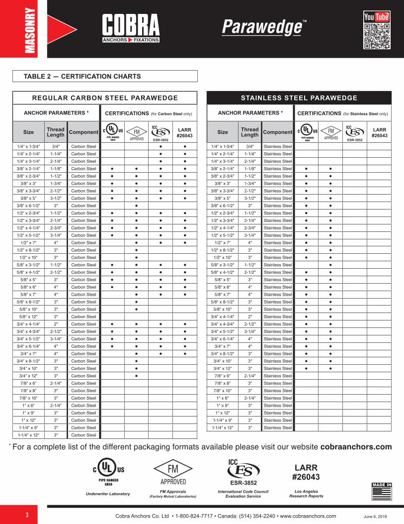
TOOLS REQUIRED
Installation instructions and warnings packaged with products must be followed precisely or holding power will be significantly lower. Safety goggles must be worn when working with all products.All test data provided were from tests performed to ASTME-488-81 and con-ducted in normal weight, hard rock aggregate concrete of the specific strength with a 28-day curing time designated in each chart.Ultimate values of tensile and shear loads shown in test data should be used purely as a guide. Actual results may vary and are dependent on such factors as concrete strength, concrete curing time, grade of steel, embedment depth, and proper installation. All drill sizes are per ANSI B212.15.
NOTE: Installing in concrete that is cured for less than 28 days will greatly reduce the anchor's strength.
PARAWEDGE concrete anchors must be installed at the recommended spacing and edge distances to obtain full working load.General industry practice for static loads is to use a safety factor of 4:1 to obtain safe working loads. In all installations, it is recommended that tests to simulate actual conditions are to be carried out to determine the suitability of the products for a particular application. For technical information and product performance data, contact Cobra Anchors Co. Ltd.
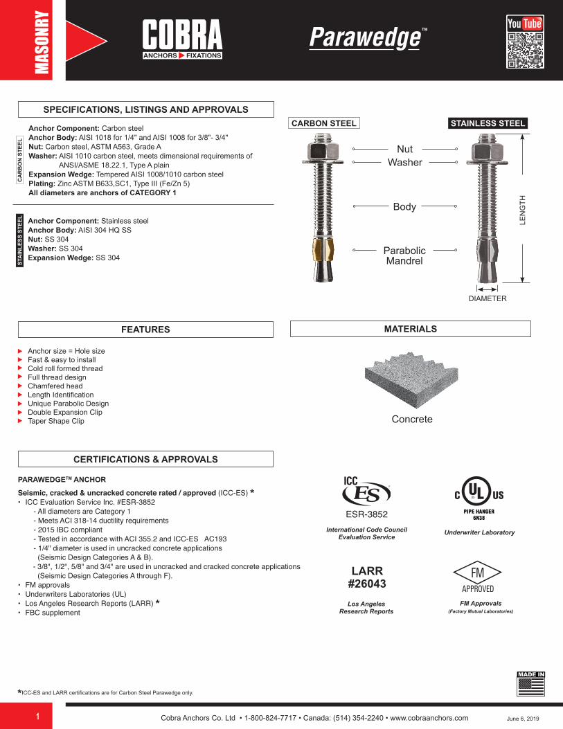
INSTALLATION INSTRUCTIONS
1. Use a carbide bit ANSI B212.15 (-1994) that is the same size as the bolt diameter. Drill hole deeper than bolt embedment (min.0.5 dia.) Do not use core bits. Maintain accurate hole size.
2. Clean hole using a dust blower or compressed air.3. Add washer and thread nut 1/8" from the top of bolt. Drive bolt into
hole through item to be fastened.4. To set, tighten nut 3 to 4 full turns or consult chart for guide installa-
tion torque. WARNING: WEAR SAFETY GOGGLES
LENGTH IDENTIFICATION CODEStamp on Anchor A B C D E F G H I J K L
Anchor Size
From: 1-1/2" 2" 2-1/2" 3" 3-1/2" 4" 4-1/2" 5" 5-1/2" 6" 6-1/2" 7"
Up to: 2" 2-1/2" 3" 3-1/2" 4" 4-1/2" 5" 5-1/2" 6" 6-1/2" 7" 7-1/2"
TABLE 1 ─ LENGTH CODE
Cobra Anchors Co. Ltd • 1-800-824-7717 • Canada: (514) 354-2240 • www.cobraanchors.com3
LARR #26043
Underwriter Laboratory Los Angeles Research Reports
FM Approvals (Factory Mutual Laboratories)
International Code Council Evaluation Service
PIPE HANGER6N38
June 6, 2019
MASO
NRY
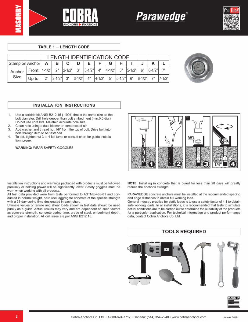
TABLE 2 — CERTIFICATION CHARTS
REGULAR CARBON STEEL PARAWEDGE
ANCHOR PARAMETERS * CERTIFICATIONS (for Carbon Steel only)
Size Thread Length Component
1/4" x 1-3/4" 3/4" Carbon Steel • •1/4" x 2-1/4" 1-1/4" Carbon Steel • •1/4" x 3-1/4" 2-1/4" Carbon Steel • •3/8" x 2-1/4" 1-1/8" Carbon Steel • • • •3/8" x 2-3/4" 1-1/2" Carbon Steel • • • •
3/8" x 3" 1-3/4" Carbon Steel • • • •3/8" x 3-3/4" 2-1/2" Carbon Steel • • • •
3/8" x 5" 3-1/2" Carbon Steel • • • •3/8" x 6-1/2" 3" Carbon Steel •1/2" x 2-3/4" 1-1/2" Carbon Steel • • • •1/2" x 3-3/4" 2-1/4" Carbon Steel • • • •1/2" x 4-1/4" 2-3/4" Carbon Steel • • • •1/2" x 5-1/2" 3-1/4" Carbon Steel • • • •
1/2" x 7" 4" Carbon Steel • • •1/2" x 8-1/2" 3" Carbon Steel •
1/2" x 10" 3" Carbon Steel •5/8" x 3-1/2" 1-1/2" Carbon Steel • • • •5/8" x 4-1/2" 2-1/2" Carbon Steel • • • •
5/8" x 5" 3" Carbon Steel • • • •5/8" x 6" 4" Carbon Steel • • • •5/8" x 7" 4" Carbon Steel • • •
5/8" x 8-1/2" 3" Carbon Steel •5/8" x 10" 3" Carbon Steel •5/8" x 12" 3" Carbon Steel
3/4" x 4-1/4" 2" Carbon Steel • • • •3/4" x 4-3/4" 2-1/2" Carbon Steel • • • •3/4" x 5-1/2" 3-1/4" Carbon Steel • • • •3/4" x 6-1/4" 4" Carbon Steel • • • •
3/4" x 7" 4" Carbon Steel • • •3/4" x 8-1/2" 3" Carbon Steel •
3/4" x 10" 3" Carbon Steel •3/4" x 12" 3" Carbon Steel •7/8" x 6" 2-1/4" Carbon Steel
7/8" x 8" 3" Carbon Steel
7/8" x 10" 3" Carbon Steel
1" x 6" 2-1/4" Carbon Steel
1" x 9" 3" Carbon Steel
1" x 12" 3" Carbon Steel
1-1/4" x 9" 3" Carbon Steel
1-1/4" x 12" 3" Carbon Steel
STAINLESS STEEL PARAWEDGE
ANCHOR PARAMETERS * CERTIFICATIONS (for Stainless Steel only)
Size Thread Length Component
1/4" x 1-3/4" 3/4" Stainless Steel
1/4" x 2-1/4" 1-1/4" Stainless Steel
1/4" x 3-1/4" 2-1/4" Stainless Steel
3/8" x 2-1/4" 1-1/8" Stainless Steel • •3/8" x 2-3/4" 1-1/2" Stainless Steel • •
3/8" x 3" 1-3/4" Stainless Steel • •3/8" x 3-3/4" 2-1/2" Stainless Steel • •
3/8" x 5" 3-1/2" Stainless Steel • •3/8" x 6-1/2" 3" Stainless Steel • •1/2" x 2-3/4" 1-1/2" Stainless Steel • •1/2" x 3-3/4" 2-1/4" Stainless Steel • •1/2" x 4-1/4" 2-3/4" Stainless Steel • •1/2" x 5-1/2" 3-1/4" Stainless Steel • •
1/2" x 7" 4" Stainless Steel • •1/2" x 8-1/2" 3" Stainless Steel • •
1/2" x 10" 3" Stainless Steel • •5/8" x 3-1/2" 1-1/2" Stainless Steel •5/8" x 4-1/2" 2-1/2" Stainless Steel • •
5/8" x 5" 3" Stainless Steel • •5/8" x 6" 4" Stainless Steel • •5/8" x 7" 4" Stainless Steel • •
5/8" x 8-1/2" 3" Stainless Steel • •5/8" x 10" 3" Stainless Steel • •
3/4" x 4-1/4" 2" Stainless Steel • •3/4" x 4-3/4" 2-1/2" Stainless Steel • •3/4" x 5-1/2" 3-1/4" Stainless Steel • •3/4" x 6-1/4" 4" Stainless Steel • •
3/4" x 7" 4" Stainless Steel • •3/4" x 8-1/2" 3" Stainless Steel • •
3/4" x 10" 3" Stainless Steel • •3/4" x 12" 3" Stainless Steel • •7/8" x 6" 2-1/4" Stainless Steel
7/8" x 8" 3" Stainless Steel
7/8" x 10" 3" Stainless Steel
1" x 6" 2-1/4" Stainless Steel
1" x 9" 3" Stainless Steel
1" x 12" 3" Stainless Steel
1-1/4" x 9" 3" Stainless Steel
1-1/4" x 12" 3" Stainless Steel
LARR #26043
MADE IN
* For a complete list of the different packaging formats available please visit our website cobraanchors.com
LARR #26043
ESR-3852ESR-3852PIPE HANGER
6N38PIPE HANGER
6N38
ESR-3852

Cobra Anchors Co. Ltd • 1-800-824-7717 • Canada: (514) 354-2240 • www.cobraanchors.com4 June 6, 2019
MASO
NRY
Opposite side view
PARAWEDGE
Expansion element(Wedge clip)
Washer
NutAnchor body
Mandrel
Collar
Anchor thread
Length codeUNC
Components
(l anch)
h min
h nom
d bit
h0
h ef
T inst
FIGURE 1 ─ PARAWEDGETM ANCHOR ASSEMBLY
FIGURE 2 ─ PARAWEDGETM ANCHOR DETAIL
TABLE 3 ─ PARAWEDGETM ANCHOR DESIGN AND INSTALLATION INFORMATIN1 - FOR CARBON STEEL
Setting and DesignInformation Symbol Units
Nominal anchor diameter
1/4" 3/8" 1/2" 5/8" 3/4"
Anchor O.D. da(d0)2 in.(mm)
0.250(6.4)
0.375(9.5)
0.500(12.7)
0.625(15.9)
0.750(19.1)
Nominal drill bit dia. dbitin.
(mm)1/4
(6.4)3/8
(9.5)1/2
(12.7)5/8
(15.9)3/4
(19.1)
Nominal embedment depth hnom
in.(mm)
1-3/4(44)
2-1/2(63)
2-7/8(73)
3-1/2(89)
4(102)
Effective min. embedment hef
in.(mm)
1-1/2(38)
2(51)
2-1/4(57)
2-3/4(70)
3-1/8(79)
Min. hole depth hholein.
(mm)2
(51)2-5/8(67)
3(76)
3-5/8(92)
4-1/8(105)
Min. member tickness hminin.
(mm)4
(102)4
(102)4-1/2(114)
5-1/2(140)
6(152)
Critical edge distance cacin.
(mm)2-1/2(64)
5-1/2(140)
7(178)
6(152)
9(229)
Min. edge distance cminin.
(mm)2
(51)2-1/2(64)
3-1/4(83)
4-1/2(114)
4-3/4(121)
Min. anchor spacing sminin.
(mm)3
(76)3
(76)6-1/2(165)
5-1/2(140)
6-1/4(159)
Installation torque tinstft-lb
(Nm)10
(14)30
(41)50
(68)70
(95)120
(163)
For SI: 1 inch = 25.4 mm, 1lbf = 4.45 N, 1Psi = 0.006895 MPa. For pound-in units: 1 mm = 0.03937 inches.
1 The information presented in this table is to be used in conjunction with the design criteria of ACI 318-14 Chapter 17 or ACI 318-11 Appendix D, as applicable.2 The notation in parenthesis is for the 2006 IBC.

Cobra Anchors Co. Ltd • 1-800-824-7717 • Canada: (514) 354-2240 • www.cobraanchors.com5 June 6, 2019
MASO
NRY
TABLE 4 ─ TENSION DESIGN INFORMATION FOR PARAWEDGETM ANCHOR 1.2 - FOR CARBON STEEL
DESIGN INFORMATION Symbol UnitsNOMINAL ANCHOR DIAMETER
1/4" 3/8" 1/2" 5/8" 3/4"
Anchor category 1, 2 or 3 - 1
Effective min. embedment hefin.
(mm)1-1/2(38)
2(51)
2-1/4(57)
2-3/4(70)
3-1/8(79)
STEEL STRENGTH IN TENSION
Min. specified yield strength fyapsi
(N/mm²)55,000(379)
50,000(345)
50,000(345)
50,000(345)
50,000(345)
Min. specified ult. strength futapsi
(N/mm²)80,000(552)
65,000(448)
65,000(448)
65,000(448)
65,000(448)
Effective tensile stress area (neck) Asein²
(mm²)0.0254(16.16)
0.0556(35.29)
0.1018(64.64)
0.1810(114.91)
0.2697(171.27)
Steel strength in tension4 (neck) Nsalb
(kN)2,035(9.0)
3,610(16.0)
6,615(29.4)
11,760(52.3)
17,530(88.0)
Reduction factor Ø for tension, steel strength³ 0.75
CONCRETE BREAKOUT STRENGTH IN TENSION
Effective min. embedment hefin.
(mm)1-1/2(38)
2(51)
2-1/4(57)
2-3/4(70)
3-1/8(79)
Effectiveness factor Kuncr
uncracked concrete² Kuncr - 24 24 27 27 27
Effectiveness factor Kcr
cracked concrete² Kcr - NA 17 21 21 21
Critical edge distance Cacin.
(mm)2-1/2(64)
5-1/2(140)
7(178)
6(152)
9(229)
Reduction factor Ø for concrete breakout³ 0.65 (Condition B)
PULLOUT STRENGTH IN TENSION
Pullout strength uncracked concrete (2,500 psi) Np,uncr
lb
(kN)
1,795
(8.0)
3,800
(16.9)See Note 6 See Note 6 See Note 6
Pullout strength cracked/seismic concrete (2,500 psi)5.7
Np,cr
Neq
lb
(kN)NA
1,740
(7.7)See Note 6 See Note 6 See Note 6
Reduction factor Ø for concrete pullout³ (uncracked/cracked/seismic) 0.65 (Condition B)
For SI: 1 inch = 25.4 mm, 1lbf = 4.45 N, 1Psi = 0.006895 MPa. For pound-in units: 1 mm = 0.03937 inches.
1 The data in this table is intended to be used with the design provisions of ACI 318-14 Chapter 17 or ACI 318-11 Appendix D, as applicable; for anchors resisting seismic load combinations the additional requirements of ACI 318-14 17.2.3 or ACI 318-11 D.3.3, as applicable, must apply.2 Installation must comply with published instructions and details.3 All values of Ø apply to the load combinations of IBC Section 1605.2, ACI 318-14 Section 5.3 or ACI 318-11 Section 9.2 as applicable. If the load combinations of ACI 318-11 Appendix C are used, then the appropriate value of Ø must be determined in accordance with ACI 318-11 D.4.4. For reinforcement that meets ACI 318-14 Chapter 17 or ACI 318-11 Appendix D requirements for Condition A, see ACI 318-14 17.3.3.(c) or ACI 318-11 D.4.3 (c), as applicable, for the appropriate Ø factor when the load combinations of IBC Section 1605.2, ACI 318-14 Section 5.3 or ACI 318-11 Section 9.2, as applicable, are used.4 The carbon steel is a ductile steel element as defined by ACI 318-14 2.3 or ACI 318-11 D.1, as applicable.5 See Section 4.1.4 of this report, NA (not applicable) denotes that this value is not available for design.6 Pullout strength does not control design of indicated anchors.7 Tabulated values for characteristic pullout strength in tension are for seismic applications and based an test results in accordance with ACI 355.2, Section 9.5.
Cobra Anchors Co. Ltd • 1-800-824-7717 • Canada: (514) 354-2240 • www.cobraanchors.com6 June 6, 2019
MASO
NRY
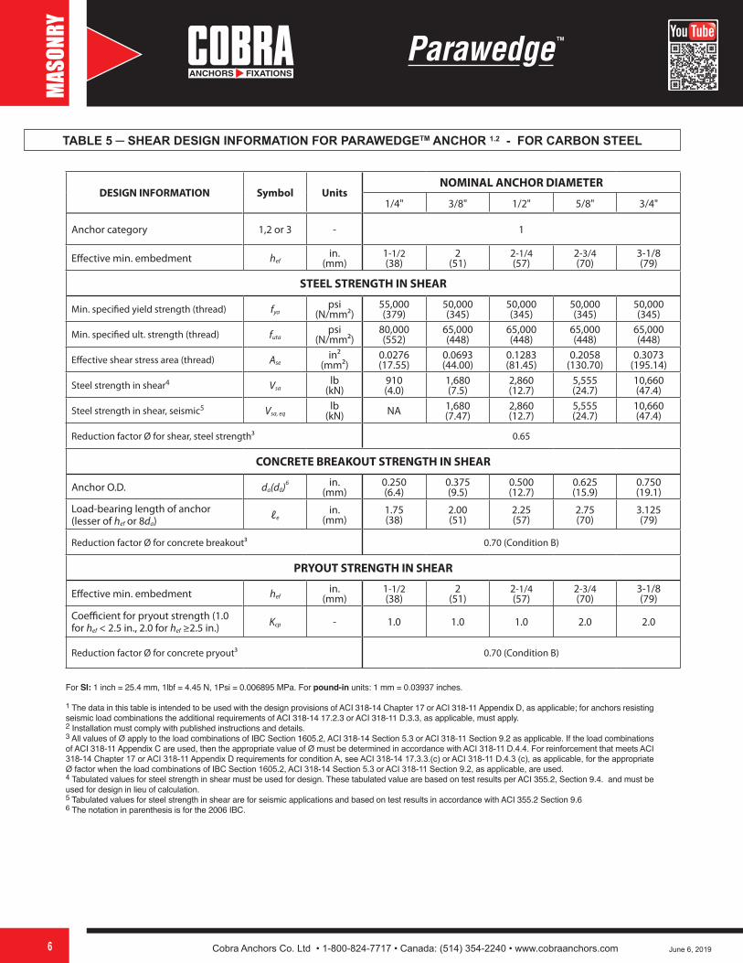
TABLE 5 ─ SHEAR DESIGN INFORMATION FOR PARAWEDGETM ANCHOR 1.2 - FOR CARBON STEEL
DESIGN INFORMATION Symbol UnitsNOMINAL ANCHOR DIAMETER
1/4" 3/8" 1/2" 5/8" 3/4"
Anchor category 1,2 or 3 - 1
Effective min. embedment hefin.
(mm)1-1/2(38)
2(51)
2-1/4(57)
2-3/4(70)
3-1/8(79)
STEEL STRENGTH IN SHEAR
Min. specified yield strength (thread) fyapsi
(N/mm²)55,000(379)
50,000(345)
50,000(345)
50,000(345)
50,000(345)
Min. specified ult. strength (thread) futapsi
(N/mm²)80,000(552)
65,000(448)
65,000(448)
65,000(448)
65,000(448)
Effective shear stress area (thread) Asein²
(mm²)0.0276(17.55)
0.0693(44.00)
0.1283(81.45)
0.2058(130.70)
0.3073(195.14)
Steel strength in shear4 Vsalb
(kN)910(4.0)
1,680(7.5)
2,860(12.7)
5,555(24.7)
10,660(47.4)
Steel strength in shear, seismic5 Vsa, eqlb
(kN) NA 1,680(7.47)
2,860(12.7)
5,555(24.7)
10,660(47.4)
Reduction factor Ø for shear, steel strength³ 0.65
CONCRETE BREAKOUT STRENGTH IN SHEAR
Anchor O.D. da(d0)6 in.(mm)
0.250(6.4)
0.375(9.5)
0.500(12.7)
0.625(15.9)
0.750(19.1)
Load-bearing length of anchor (lesser of hef or 8da) ℓe
in.(mm)
1.75(38)
2.00(51)
2.25(57)
2.75(70)
3.125(79)
Reduction factor Ø for concrete breakout³ 0.70 (Condition B)
PRYOUT STRENGTH IN SHEAR
Effective min. embedment hefin.
(mm)1-1/2(38)
2(51)
2-1/4(57)
2-3/4(70)
3-1/8(79)
Coefficient for pryout strength (1.0 for hef < 2.5 in., 2.0 for hef ≥2.5 in.) Kcp - 1.0 1.0 1.0 2.0 2.0
Reduction factor Ø for concrete pryout³ 0.70 (Condition B)
For SI: 1 inch = 25.4 mm, 1lbf = 4.45 N, 1Psi = 0.006895 MPa. For pound-in units: 1 mm = 0.03937 inches.
1 The data in this table is intended to be used with the design provisions of ACI 318-14 Chapter 17 or ACI 318-11 Appendix D, as applicable; for anchors resisting seismic load combinations the additional requirements of ACI 318-14 17.2.3 or ACI 318-11 D.3.3, as applicable, must apply.2 Installation must comply with published instructions and details.3 All values of Ø apply to the load combinations of IBC Section 1605.2, ACI 318-14 Section 5.3 or ACI 318-11 Section 9.2 as applicable. If the load combinations of ACI 318-11 Appendix C are used, then the appropriate value of Ø must be determined in accordance with ACI 318-11 D.4.4. For reinforcement that meets ACI 318-14 Chapter 17 or ACI 318-11 Appendix D requirements for condition A, see ACI 318-14 17.3.3.(c) or ACI 318-11 D.4.3 (c), as applicable, for the appropriate Ø factor when the load combinations of IBC Section 1605.2, ACI 318-14 Section 5.3 or ACI 318-11 Section 9.2, as applicable, are used.4 Tabulated values for steel strength in shear must be used for design. These tabulated value are based on test results per ACI 355.2, Section 9.4. and must be used for design in lieu of calculation.5 Tabulated values for steel strength in shear are for seismic applications and based on test results in accordance with ACI 355.2 Section 9.66 The notation in parenthesis is for the 2006 IBC.
Cobra Anchors Co. Ltd • 1-800-824-7717 • Canada: (514) 354-2240 • www.cobraanchors.com7
S
June 6, 2019
MASO
NRY
WARNINGS:Installation instructions and warnings packaged with products must be followed precisely or holding power will be significantly lower. Safety goggles must be worn when working with all products.All tests data given were from tests performed to ASTME-488-81 conducted in normal weight, hard rock aggregate concrete of the specific strength with a 28 day cure time designated in each chart.Ultimate values of tensile and shear loads shown in test data should be used purely as a guide. Actual results may vary and are dependent on such factors as concrete strength, concrete cure time, grade of steel, embedment depth, and proper installation. All drill sizes are per ANSI B212.15.
Using mechanical anchors in concrete cured less than 28 days will greatly reduce anchor strength.
Note: PARAWEDGETM concrete anchors must be installed at the recommended spacing and edge distance to obtain full working load. (Table 6 & Table 7)General industry practice for static loads is to use a safety factor of 4:1 to obtain safe working loads. In all installations, it is recommended that tests to simulate actual conditions are to be carried out to determine the suitability of the products for a particular application.
NOTE: Using in concrete cured less than 28 days will greatly reduce anchor strength.
CAUTION: WEAR SAFETY GOGGLES
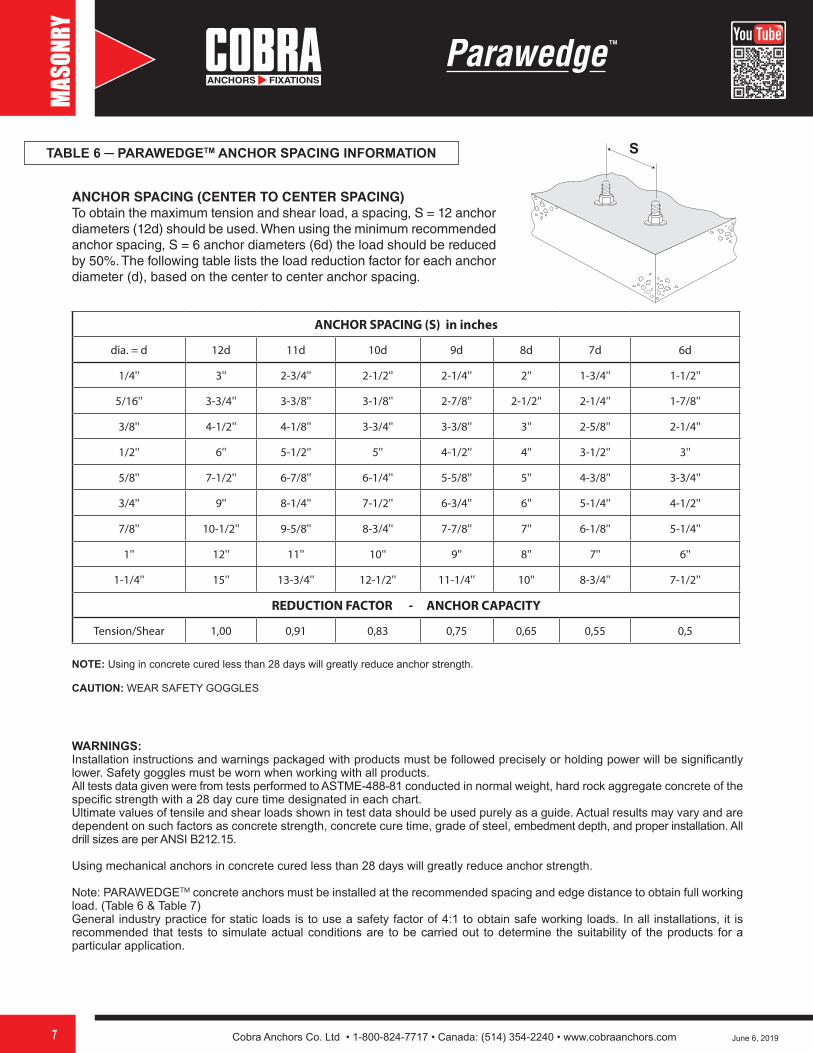
ANCHOR SPACING (CENTER TO CENTER SPACING)To obtain the maximum tension and shear load, a spacing, S = 12 anchor diameters (12d) should be used. When using the minimum recommended anchor spacing, S = 6 anchor diameters (6d) the load should be reduced by 50%. The following table lists the load reduction factor for each anchor diameter (d), based on the center to center anchor spacing.
ANCHOR SPACING (S) in inches
dia. = d 12d 11d 10d 9d 8d 7d 6d
1/4'' 3'' 2-3/4'' 2-1/2'' 2-1/4'' 2'' 1-3/4'' 1-1/2''
5/16'' 3-3/4'' 3-3/8'' 3-1/8'' 2-7/8'' 2-1/2'' 2-1/4'' 1-7/8''
3/8'' 4-1/2'' 4-1/8'' 3-3/4'' 3-3/8'' 3'' 2-5/8'' 2-1/4''
1/2'' 6'' 5-1/2'' 5'' 4-1/2'' 4'' 3-1/2'' 3''
5/8'' 7-1/2'' 6-7/8'' 6-1/4'' 5-5/8'' 5'' 4-3/8'' 3-3/4''
3/4'' 9'' 8-1/4'' 7-1/2'' 6-3/4'' 6'' 5-1/4'' 4-1/2''
7/8'' 10-1/2'' 9-5/8'' 8-3/4'' 7-7/8'' 7'' 6-1/8'' 5-1/4''
1'' 12'' 11'' 10'' 9'' 8'' 7'' 6''
1-1/4'' 15'' 13-3/4'' 12-1/2'' 11-1/4'' 10'' 8-3/4'' 7-1/2''
REDUCTION FACTOR - ANCHOR CAPACITY
Tension/Shear 1,00 0,91 0,83 0,75 0,65 0,55 0,5
TABLE 6 ─ PARAWEDGETM ANCHOR SPACING INFORMATION

Cobra Anchors Co. Ltd • 1-800-824-7717 • Canada: (514) 354-2240 • www.cobraanchors.com8
EE
June 6, 2019
MASO
NRY
ANCHOR SPACING (E) in inches
dia. = d 12d 11d 10d 9d 8d 7d 6d
1/4'' 3'' 2-3/4'' 2-1/2'' 2-1/4'' 2'' 1-3/4'' 1-1/2''
5/16'' 3-3/4'' 3-1/2'' 3-1/8'' 2-7/8'' 2-1/2'' 2-1/4'' 1-7/8''
3/8'' 4-1/2'' 4-1/8'' 3-3/4'' 3-3/8'' 3'' 2-5/8'' 2-1/4''
1/2'' 6'' 5-1/2'' 5'' 4-1/2'' 4'' 3-1/2'' 3''
5/8'' 7-1/2'' 6-7/8'' 6-1/4'' 5-5/8'' 5'' 4-3/8'' 3-3/4''
3/4'' 9'' 8-1/4'' 7-1/2'' 6-3/4'' 6'' 5-1/4'' 4-1/2''
7/8'' 10-1/2'' 9-5/8'' 8-3/4'' 7-7/8'' 7'' 6-1/8'' 5-1/4''
1'' 12'' 11'' 10'' 9'' 8'' 7'' 6''
1-1/4'' 15'' 13-1/4'' 12-1/2'' 11-1/4'' 10'' 8-3/4'' 7-1/2''
REDUCTION FACTOR - ANCHOR CAPACITYTension 1,00 0,91 0,83 0,75 0,65 0,55 0,5
Shear 1,00 0,97 0,94 0,91 0,89 0,83 0,8
NOTE: Using in concrete cured less than 28 days will greatly reduce anchor strength.
CAUTION: WEAR SAFETY GOGGLES
EDGE DISTANCE (CENTER TO EDGE SPACING)To obtain the maximum tension and shear load, an edge distance, E = 12 anchor diameters (12d) should be used. When using the minimum recommended edge distance, E = 6 anchor diameters (6d), the tension load should be reduced by 50% and the shear load by 20%. The following table lists the load reduction factor for each anchor diameter (d) based on the anchor center to edge distance.
TABLE 7 ─ PARAWEDGETM ANCHOR EDGE DISTANCE INFORMATION
WARNINGS:Installation instructions and warnings packaged with products must be followed precisely or holding power will be significantly lower. Safety goggles must be worn when working with all products.All tests data given were from tests performed to ASTME-488-81 conducted in normal weight, hard rock aggregate concrete of the specific strength with a 28 day cure time designated in each chart.Ultimate values of tensile and shear loads shown in test data should be used purely as a guide. Actual results may vary and are dependent on such factors as concrete strength, concrete cure time, grade of steel, embedment depth, and proper installation. All drill sizes are per ANSI B212.15.
Using mechanical anchors in concrete cured less than 28 days will greatly reduce anchor strength.
Note: PARAWEDGETM concrete anchors must be installed at the recommended spacing and edge distance to obtain full working load.(Table 6 & Table 7)General industry practice for static loads is to use a safety factor of 4:1 to obtain safe working loads. In all installations, it is recom-mended that tests to simulate actual conditions are to be carried out to determine the suitability of the products for a particular application.
Cobra Anchors Co. Ltd • 1-800-824-7717 • Canada: (514) 354-2240 • www.cobraanchors.com9 June 6, 2019
MASO
NRY
REGULAR CARBON STEEL PARAWEDGETM
ANCHOR PARAMETERS *SAFE WORKING LOAD 4:1 **
Concrete: 3,000 psi Concrete: 4,000 psi Concrete: 6,000 psi
Size Component Drill Size
Installation Torque ft.lb
Nominal Embedment
TENSIONlb
SHEARlb
TENSIONlb
SHEARlb
TENSIONlb
SHEARlb
1/4" Carbon Steel 1/4" 101-1/8" 269 228 311 228 380 228
1-3/4" 449 228 449 228 449 228
2-3/4" 449 228 449 228 449 228
3/8" Carbon Steel 3/8" 30
1-5/8" 392 392 453 420 555 420
2" 604 420 697 420 854 420
2-1/4" 761 420 878 420 903 420
2-3/8" 844 420 903 420 903 420
2-1/2" 903 420 903 420 903 420
4-1/4" 903 420 903 420 903 420
1/2" Carbon Steel 1/2" 50
2-1/2" 949 715 1096 715 1342 715
2-7/8" 1248 715 1441 715 1654 715
3-1/2" 1654 715 1654 715 1654 715
4-1/8" 1654 715 1654 715 1654 715
6" 1654 715 1654 715 1654 715
6" 1654 715 1654 715 1654 715
6" 1654 715 1654 715 1654 715
5/8" Carbon Steel 5/8" 70
2-7/8" 1145 1145 1322 1322 1620 1389
3" 1248 1248 1441 1389 1765 1389
3-1/2" 1686 1389 1947 1389 2384 1389
4" 2166 1389 2501 1389 2940 1389
4-1/2" 2685 1389 2940 1389 2940 1389
4-5/8" 2820 1389 2940 1389 2940 1389
7" 2940 1389 2940 1389 2940 1389
7" 2940 1389 2940 1389 2940 1389
3/4" Carbon Steel 3/4" 120
3-3/8" 1461 2665 1688 2665 2067 2665
4" 2042 2665 2358 2665 2888 2665
4-3/4" 2820 2665 3256 2665 3988 2665
5" 3097 2665 3577 2665 4380 2665
5-1/2" 3677 2665 4246 2665 4383 2665
6" 4289 2665 4383 2665 4383 2665
8" 4383 2665 4383 2665 4383 2665
8" 4383 2665 4383 2665 4383 2665
7/8" Carbon Steel 7/8" 2004" - - 4688 - 4688 -
4" - - 4688 - 4688 -
4" - - 4688 - 4688 -
1" Carbon Steel 1" 2504-1/2" - - 5750 - 5750 -
4-1/2" - - 5750 - 5750 -
4-1/2" - - 5750 - 5750 -
1-1/4" Carbon Steel 1-1/4" 4005-1/2" - - 8750 - 8750 -
5-1/2" - - 8750 - 8750 -
MADE IN
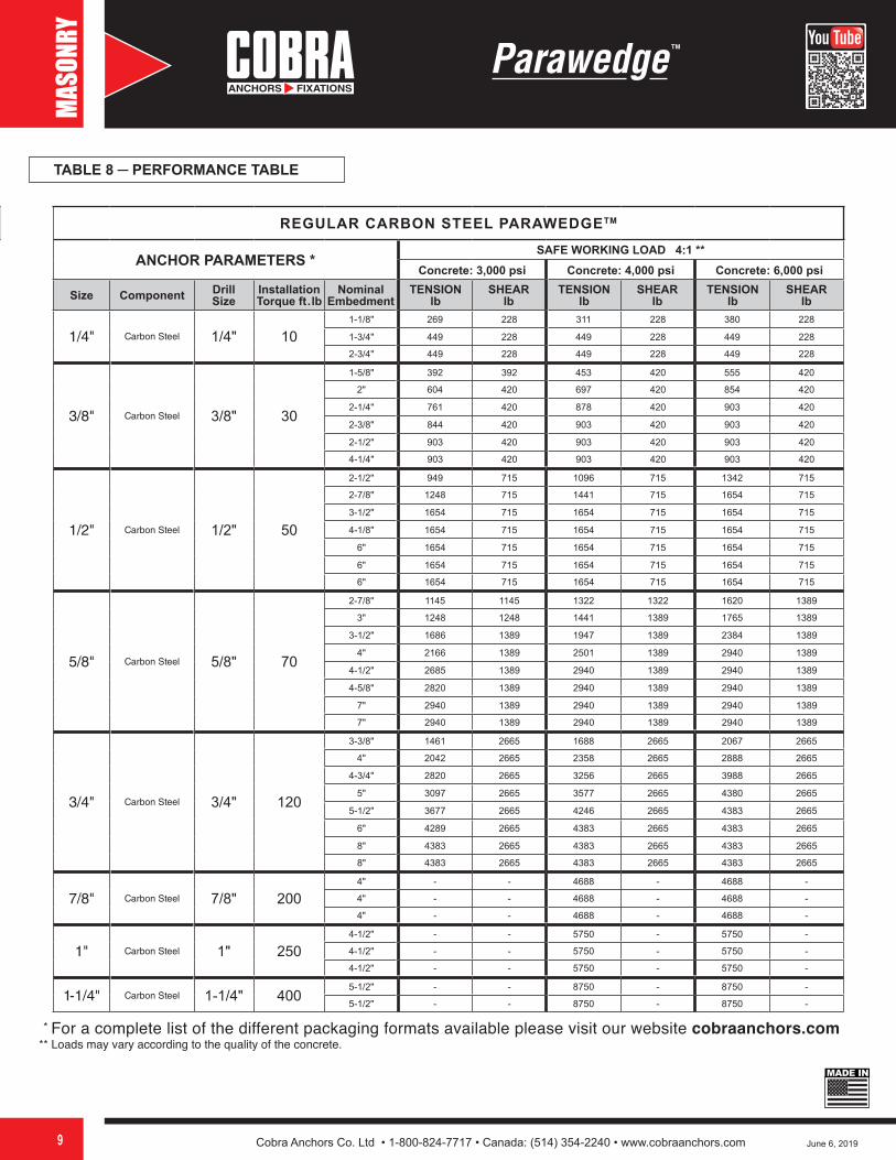
TABLE 8 ─ PERFORMANCE TABLE
REGULAR CARBON STEEL PARAWEDGETM
ANCHOR PARAMETERS *SAFE WORKING LOAD 4:1 **
Concrete: 3,000 psi Concrete: 4,000 psi Concrete: 6,000 psi
Size Component Drill Size
Installation Torque ft.lb
Nominal Embedment
Thread Length
TENSIONlb
SHEARlb
TENSIONlb
SHEARlb
TENSIONlb
SHEARlb
1/4" x 1-3/4" Carbon Steel 1/4" 10 1-1/8" 3/4" 269 228 311 228 380 228
1/4" x 2-1/4" Carbon Steel 1/4" 10 1-3/4" 1-1/4" 449 228 449 228 449 228
1/4" x 3-1/4" Carbon Steel 1/4" 10 2-3/4" 2-1/4" 449 228 449 228 449 228
3/8" x 2-1/4" Carbon Steel 3/8" 30 1-5/8" 1-1/8" 392 392 453 420 555 420
3/8" x 2-3/4" Carbon Steel 3/8" 30 2" 1-1/2" 604 420 697 420 854 420
3/8" x 3" Carbon Steel 3/8" 30 2-1/4" 1-3/4" 761 420 878 420 903 420
3/8" x 3-3/4" Carbon Steel 3/8" 30 2-3/8" 2-1/2" 844 420 903 420 903 420
3/8" x 5" Carbon Steel 3/8" 30 2-1/2" 3-1/2" 903 420 903 420 903 420
3/8" x 6-1/2" Carbon Steel 3/8" 30 4-1/4" 3" 903 420 903 420 903 420
1/2" x 2-3/4" Carbon Steel 1/2" 50 2-1/2" 1-1/2" 949 715 1096 715 1342 715
1/2" x 3-3/4" Carbon Steel 1/2" 50 2-7/8" 2-1/4" 1248 715 1441 715 1654 715
1/2" x 4-1/4" Carbon Steel 1/2" 50 3-1/2" 2-3/4" 1654 715 1654 715 1654 715
1/2" x 5-1/2" Carbon Steel 1/2" 50 4-1/8" 3-1/4" 1654 715 1654 715 1654 715
1/2" x 7" Carbon Steel 1/2" 50 6" 4" 1654 715 1654 715 1654 715
1/2" x 8-1/2" Carbon Steel 1/2" 50 6" 3" 1654 715 1654 715 1654 715
1/2" x 10" Carbon Steel 1/2" 50 6" 3" 1654 715 1654 715 1654 715
5/8" x 3-1/2" Carbon Steel 5/8" 70 2-7/8" 1-1/2" 1145 1145 1322 1322 1620 1389
5/8" x 4-1/2" Carbon Steel 5/8" 70 3" 2-1/2" 1248 1248 1441 1389 1765 1389
5/8" x 5" Carbon Steel 5/8" 70 3-1/2" 3" 1686 1389 1947 1389 2384 1389
5/8" x 6" Carbon Steel 5/8" 70 4" 4" 2166 1389 2501 1389 2940 1389
5/8" x 7" Carbon Steel 5/8" 70 4-1/2" 4" 2685 1389 2940 1389 2940 1389
5/8" x 8-1/2" Carbon Steel 5/8" 70 4-5/8" 3" 2820 1389 2940 1389 2940 1389
5/8" x 10" Carbon Steel 5/8" 70 7" 3" 2940 1389 2940 1389 2940 1389
5/8" x 12" Carbon Steel 5/8" 70 7" 3" 2940 1389 2940 1389 2940 1389
3/4" x 4-1/4" Carbon Steel 3/4" 120 3-3/8" 2" 1461 2665 1688 2665 2067 2665
3/4" x 4-3/4" Carbon Steel 3/4" 120 4" 2-1/2" 2042 2665 2358 2665 2888 2665
3/4" x 5-1/2" Carbon Steel 3/4" 120 4-3/4" 3-1/4" 2820 2665 3256 2665 3988 2665
3/4" x 6-1/4" Carbon Steel 3/4" 120 5" 4" 3097 2665 3577 2665 4380 2665
3/4" x 7" Carbon Steel 3/4" 120 5-1/2" 4" 3677 2665 4246 2665 4383 2665
3/4" x 8-1/2" Carbon Steel 3/4" 120 6" 3" 4289 2665 4383 2665 4383 2665
3/4" x 10" Carbon Steel 3/4" 120 8" 3" 4383 2665 4383 2665 4383 2665
3/4" x 12" Carbon Steel 3/4" 120 8" 3" 4383 2665 4383 2665 4383 2665
7/8" x 6" Carbon Steel 7/8" 200 4" 2-1/4" - - 4688 - 4688 -
7/8" x 8" Carbon Steel 7/8" 200 4" 3" - - 4688 - 4688 -
7/8" x 10" Carbon Steel 7/8" 200 4" 3" - - 4688 - 4688 -
1" x 6" Carbon Steel 1" 250 4-1/2" 2-1/4" - - 5750 - 5750 -
1" x 9" Carbon Steel 1" 250 4-1/2" 3" - - 5750 - 5750 -
1" x 12" Carbon Steel 1" 250 4-1/2" 3" - - 5750 - 5750 -
1-1/4" x 9" Carbon Steel 1-1/4" 400 5-1/2" 3" - - 8750 - 8750 -
1-1/4" x 12" Carbon Steel 1-1/4" 400 5-1/2" 3" - - 8750 - 8750 -
* For a complete list of the different packaging formats available please visit our website cobraanchors.com ** Loads may vary according to the quality of the concrete.

Cobra Anchors Co. Ltd • 1-800-824-7717 • Canada: (514) 354-2240 • www.cobraanchors.com10 June 6, 2019
MASO
NRY
MADE IN
STAINLESS STEEL PARAWEDGE
ANCHOR PARAMETERS *SAFE WORKING LOAD 4:1 **
Concrete: 3,000 psi Concrete: 4,000 psi Concrete: 6,000 psi
Diameter Component Drill Size
Installation Torque ft.lb
Nominal Embedment
TENSIONlb
SHEARlb
TENSIONlb
SHEARlb
TENSIONlb
SHEARlb
1/4" Stainless Steel 1/4" 101-1/8" 269 228 311 228 380 228
1-3/4" 449 228 449 228 449 228
2-3/4" 449 228 449 228 449 228
3/8" Stainless Steel 3/8" 30
1-5/8" 392 392 453 420 555 420
2" 604 420 697 420 854 420
2-1/4" 761 420 878 420 903 420
2-3/8" 844 420 903 420 903 420
2-1/2" 903 420 903 420 903 420
4-1/4" 903 420 903 420 903 420
1/2" Stainless Steel 1/2" 50
2-1/2" 949 715 1096 715 1342 715
2-7/8" 1248 715 1441 715 1654 715
3-1/2" 1654 715 1654 715 1654 715
4-1/8" 1654 715 1654 715 1654 715
6" 1654 715 1654 715 1654 715
6" 1654 715 1654 715 1654 715
6" 1654 715 1654 715 1654 715
5/8" *** Stainless Steel 5/8" 70
2-7/8" 1145 1145 1322 1322 1620 1389
3" 1248 1248 1441 1389 1765 1389
3-1/2" 1686 1389 1947 1389 2384 1389
4" 2166 1389 2501 1389 2940 1389
4-1/2" 2685 1389 2940 1389 2940 1389
4-5/8" 2820 1389 2940 1389 2940 1389
7" 2940 1389 2940 1389 2940 1389
3/4" *** Stainless Steel 3/4" 120
3-3/8" 1461 2665 1688 2665 2067 2665
4" 2042 2665 2358 2665 2888 2665
4-3/4" 2820 2665 3256 2665 3988 2665
5" 3097 2665 3577 2665 4380 2665
5-1/2" 3677 2665 4246 2665 4383 2665
6" 4289 2665 4383 2665 4383 2665
8" 4383 2665 4383 2665 4383 2665
8" 4383 2665 4383 2665 4383 2665
7/8" Stainless Steel 7/8" 2004" - - 4688 - 4688 -
4" - - 4688 - 4688 -
4" - - 4688 - 4688 -
1" Stainless Steel 1" 2504-1/2" - - 5750 - 5750 -
4-1/2" - - 5750 - 5750 -
4-1/2" - - 5750 - 5750 -
1-1/4" Stainless Steel 1-1/4" 4005-1/2" - - 8750 - 8750 -
5-1/2" - - 8750 - 8750 -
TABLE 8 ─ PERFORMANCE TABLE
* For a complete list of the different packaging formats available please visit our website cobraanchors.com ** Loads may vary according to the quality of the concrete. *** For UL approval, the minimum embedment for 5/8" and 3/4" Stainless Steel is 3-1/4"