Embed Size (px)
Citation preview

Brodogradnja/Shipbuilding/Open access Volume 68 Number 2, 2017
93
Vijayalakshmi Ramalingam
Sathia Ramalingam
Ramanagopal Srinivasan
Panneer Selvam
http://dx.doi.org/10.21278/brod68207 ISSN 0007-215X
eISSN 1845-5859
PARAMETRIC STUDY ON THE HYDRODYNAMIC RESPONSE OF
DSI POLYGONAL SHAPED FPSO
UDC 629.5.015.2:629.51:629.5.018.1:502.087
Original scientific paper
Summary
In the present paper, numerical investigations was carried out on a 1:45 scaled model of
DSI nine sided polygonal non-ship shaped FPSO, by varying different parameters of the model.
Parameters such as inlet pipe radius, and moonpool radius was considered for the study and the
variation of the RAO in surge and heave were plotted and reported in the present paper.
Previously, experiment were conducted by the author on a 1:45 scale DSI nine sided polygonal
non-ship shaped FPSO model with three different mooring arrangements viz. 100% turret
mooring, 50% vessel and 50% turret mooring, and 100% vessel mooring. Author also conducted
experiments on the model with different sizes of damping plates attached at the keel and skirt
portion of the model to study its influence on the responses of the vessel and comparison was
made with numerical result obtained from Wave analysis, MIT (WAMIT) software. Numerical
study was carried out in WAMIT on the scaled model and the results were compared with those
obtained from model tests in the wave basin.
Key words: FPSO, Turret mooring, damping plate, DSI Non ship shaped FPSO, keel plate, skirt
plate. Inlet pipe radius, moonpool radius
1. INTRODUCTION
Floating, Production, Storage and Offloading systems (FPSO) are increasingly competitive
to the traditional deepwater production solutions, e.g., SPAR, TLP and semi submersible in the
current offshore oil and gas environment. Today oil and gas industry is looking for
environmentally challenging technologies for their large production fields in deep water as well
as in arctic environment. In such situation need for an FPSO suitable for harsh environments, and
deepwater location arises. A new design of a non-ship shaped FPSO, developed by Deepwater
Structures Inc. (DSI), Houston, Texas catering to the icy waters of the arctic as well as severe sea
states of the North Sea is taken for the study.

Vijayalakshmi Ramalingam, Sathia Ramalingam, Parametric study on the hydrodynamic response
Ramanagopal Srinivasan, Panneer Selvam Of DSI polygonal shaped FPSO
94
Many researchers have studied the dynamic characteristics of ship shaped and Non ship
shaped FPSO in winds and currents using numerical and experimental methods. Thiagarajan et
al. [9] carried out numerical simulations and model testing to identify the influence of a heave
plate on the heave response of the spar. Masetti et al. [7] carried out experiments to study the
influence of different skirts on the response of monocolumn floating production structure and the
influence of variation of the external diameter along the vertical axis. Torres et al. [11] published
works by changing the internal geometry of the moonpool. Changes of the moon pool internal
geometry modified the behaviour of vertical oscillation of the water inside the moonpool.
Vijayalakshmi et al. [12] presented experiments results on 1:45 non-ship shaped FPSO model for
three different mooring configurations and for FPSO models with and without damping plates.
The effect of mooring configurations in the heave response of the FPSO and the effect of
damping plates in the heave and pitch responses of the FPSO under regular waves was
investigated. The DSI non ship shaped FPSO was numerically modeled with moon pool and
without moon pool and the effect of moon pool on the response of the structure was studied by
Vijayalakshmi et al. [13].
Goncalves et al. [3] developed a mathematical model of monocolumn floating production
structure to estimate the first order heave and pitch motions of the platform. Experimental tests
were carried out in order to calibrate this model. The response of each body was estimated
numerically using the WAMIT code. Fan et al. [2] proposed an octagonal FPSO for oil and gas
development in shallow waters. Goncalves et al. [4] conducted experimental study on Vortex
Induced motion (VIM) for monocolumn platform. Shen et al. [8] studied the hydrodynamic
characteristics of heave plates for Truss Spar; Experiments were conducted by Vijayalakshmi et
al. [14] to study the hydrodynamic response of the DSI FPSO vessel on a 1:45 scale model with
damping plates (skirt plate and keel plates). Bin et al. [1] numerically studied the damping
effects on the Mathieu instability and the mechanism of Deep draft multi-spar (DDMS), a novel
deepwater platform. Koh and Cho [5] studied the effect of heave plates at the bottom of the
cylinder. The heave plate attached at the bottom of the cylinder had a distinct advantage in
reducing the motion responses of a floating circular cylinder by increasing added mass and
damping coefficient. The aim of the present work is to study the Hydrodynamic response of DSI
non-ship shaped FPSO, catering to the icy waters of the arctic environment.
1.1. Non ship shaped vessel
DSI non-ship shaped FPSO has a monolithic non ship-shaped hull of polygonal configuration
surrounding a central double tapered conical moon pool and contains water ballast and oil
storage compartments. The exterior side walls of the hull have flat surfaces and sharp corners to
cut ice sheets, resist and break ice, and move ice pressure ridges away from the structure. An
adjustable water ballast system induces heave, roll, pitch and surge motions of the vessel to
dynamically position and manoeuvre the vessel to accomplish ice cutting, breaking and moving
operations. The moon pool shape and other appendages on the vessel provide added virtual mass
capable of increasing the natural period of the roll and heave modes. It reduces dynamic
amplification and the chance of resonance due to waves and vessel motion. This also facilitates
manoeuverability of the vessel. The vessel may be moored by a disconnectable turret buoy
received in a support frame at the bottom of the moon pool and to which flexible well risers and
mooring lines are connected. The cross sectional view, of the DSI FPSO showing all the features,
including inlet opening and moonpool details is shown in Fig.1.

Parametric study on the hydrodynamic response Vijayalakshmi Ramalingam, Sathia Ramalingam,
Of DSI polygonal shaped FPSO Ramanagopal Srinivasan, Panneer Selvam
95
Fig.1. Sectional View of DSI FPSO Vessel
A 1:45 scale model of the DSI non-ship shaped FPSO was fabricated for the experimental
study. The FPSO has a maximum diameter of 100m and height of 55.5m and is envisaged to
cater in icy waters where the water depth is 135m. Draft of the structure is 43.2 m. The vertical
center of gravity and vertical center of buoyancy are 25.56m and 17.59m, respectively. The
parameters of the DSI FPSO are given in Table 1. The special feature of this FPSO is that it is
capable of withstanding large ice loads. The type of ice in the arctic sea, its strength and the load
on the vessel due to wind and current are highly stochastic and complex in nature. Keeping the
above facts in mind the DSI-FPSO vessel was designed to face such harsh environment and the
associated loads, rather than escape from it. The key design features are: a rigid floating structure
with a large mass, a large lever arm and an ideal ice breaking slope at the ice contact face.
1.2 Ice-Breaking Capacity of the Vessel
The vessel may be moored with a corner facing the predominant drift moving direction of
ice floes. The uneven sided polygonal shape of the hull induces flexural failure of ice. Flexural
failure is also induced by pitching motion of the vessel, which can be achieved by changing
water levels in the ballast tanks. The broken pieces of ice ride down on the slope of the vessel,
and finally clear around it. The schematic diagram of ice breaking by the vessel is shown in Fig.

Vijayalakshmi Ramalingam, Sathia Ramalingam, Parametric study on the hydrodynamic response
Ramanagopal Srinivasan, Panneer Selvam Of DSI polygonal shaped FPSO
96
2. The experimental model without damping plates and with damping plates, fabricated at Indian
institute of technology – Madras used for the study is shown in Fig.3. and Fig.4.
Fig.2 Schematic view of ice breaking by DSI FPSO (courtesy by Deep Water Structure Inc. (DSI))
Fig.3 Model without damping plate Fig.4 FPSO model with damping plates

Parametric study on the hydrodynamic response Vijayalakshmi Ramalingam, Sathia Ramalingam,
Of DSI polygonal shaped FPSO Ramanagopal Srinivasan, Panneer Selvam
97
Table 1 Parameters of DSI FPSO
2. NUMERICAL STUDY
An accurate and efficient computational analysis of wave–body interaction is important in
the design of offshore structures and marine vessels. Among various numerical approaches,
panel method, a kind of boundary element method, is widely used for the numerical prediction of
response of offshore structures. WAMIT (Wave Analysis at Massachusetts Institute of
Technology) is a radiation diffraction program developed for the analysis of the interaction of
surface waves with offshore structure. Torres et al [10] carried out numerical investigation to
study the application of moonpool in monocolumn. Malta et al [6] studied the effect of moonpool
in monocolumn floaters with numerical methods (WAMIT) to emphasize the differences caused
with 2 different hull geometries.
The non ship shaped FPSO vessel on which the experiments were conducted was modeled
using WAMIT higher order panel method. The advantage of panel method is that the problem is
reduced to a two-dimensional problem instead of a three dimensional problem. Parametric study
was carried out for the following models
FPSO with 0.1 m keel and 0.1 m skirt plate (FPSO K1S1)
FPSO with 0.2 m keel and 0.1 m skirt plate (FPSO K2S1)
FPSO with 0.3 m keel and 0.1 m skirt plate (FPSO K3S1)
2.1. Modeling of geometry using Multisurf
Multisurf is a computer aided design (CAD) package for parametric design of 3D
geometric objects involving free form curves and surfaces. The model surface is subdivided into
Parameter Prototype Model (1:45)
Weight (W) 2495 × 103 kN 27.38 kN
Freeboard 12.3 m 0.27 m
Water depth (d) 135 m 3.0 m
Height of hull 55.5 m 1.23 m
Diameter of hull (B) 100.8 m 2.24 m
Center of gravity (KG) 25.56 m 0.568 m
Center of buoyancy (KB) 17.59 m 0.39 m
Radius of Rxx
Gyration Ryy
Rzz
25.29 m
25.29 m
24.87 m
0.56 m
0.56 m
0.55 m
Meta-center (GM) 1.6 m 0.035 m
Vijayalakshmi Ramalingam, Sathia Ramalingam, Parametric study on the hydrodynamic response
Ramanagopal Srinivasan, Panneer Selvam Of DSI polygonal shaped FPSO
98
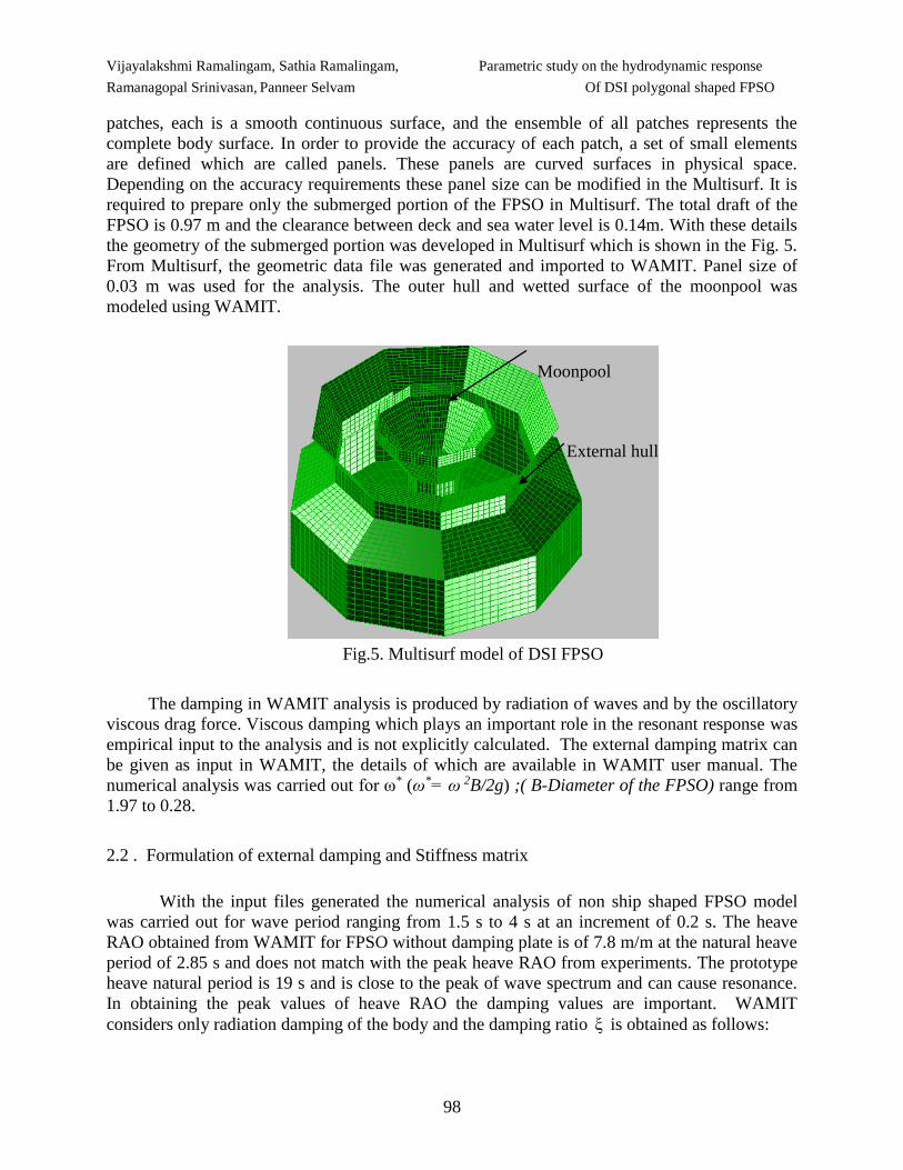
patches, each is a smooth continuous surface, and the ensemble of all patches represents the
complete body surface. In order to provide the accuracy of each patch, a set of small elements
are defined which are called panels. These panels are curved surfaces in physical space.
Depending on the accuracy requirements these panel size can be modified in the Multisurf. It is
required to prepare only the submerged portion of the FPSO in Multisurf. The total draft of the
FPSO is 0.97 m and the clearance between deck and sea water level is 0.14m. With these details
the geometry of the submerged portion was developed in Multisurf which is shown in the Fig. 5.
From Multisurf, the geometric data file was generated and imported to WAMIT. Panel size of
0.03 m was used for the analysis. The outer hull and wetted surface of the moonpool was
modeled using WAMIT.
Fig.5. Multisurf model of DSI FPSO
The damping in WAMIT analysis is produced by radiation of waves and by the oscillatory
viscous drag force. Viscous damping which plays an important role in the resonant response was
empirical input to the analysis and is not explicitly calculated. The external damping matrix can
be given as input in WAMIT, the details of which are available in WAMIT user manual. The
numerical analysis was carried out for ω* (ω*= ω 2B/2g) ;( B-Diameter of the FPSO) range from
1.97 to 0.28.
2.2 . Formulation of external damping and Stiffness matrix
With the input files generated the numerical analysis of non ship shaped FPSO model
was carried out for wave period ranging from 1.5 s to 4 s at an increment of 0.2 s. The heave
RAO obtained from WAMIT for FPSO without damping plate is of 7.8 m/m at the natural heave
period of 2.85 s and does not match with the peak heave RAO from experiments. The prototype
heave natural period is 19 s and is close to the peak of wave spectrum and can cause resonance.
In obtaining the peak values of heave RAO the damping values are important. WAMIT
considers only radiation damping of the body and the damping ratio ξ is obtained as follows:
External hull
Moonpool
Parametric study on the hydrodynamic response Vijayalakshmi Ramalingam, Sathia Ramalingam,
Of DSI polygonal shaped FPSO Ramanagopal Srinivasan, Panneer Selvam
99
33
33
ξ2 Δ ωn
B
A
= 1.35 % = 0.0135, where the heave damping,
33B = 0.194 t-rad/s,
mass, Δ = 0.29 t, added mass in heave, 33A = 2.95 t, correspond to the natural frequency, nω =
2.2 rad/sec (natural period of 2.85 sec). In other words, the heave radiation damping ( ξ )
considered by WAMIT is 0.0135 and hence at this damping level the results of WAMIT severely
overestimates the motion response in heave as compared to those from experiments. The
measured heave damping in the model is 0.102 from the free heave vibration test. Using the
provision to input dimensional external damping in WAMIT by the user, the experimentally
obtained damping has been input to WAMIT. The additional hydrodynamic damping values
input to WAMIT analysis is tabulated in Table 2.
Table 2 Additional hydrodynamic damping input to WAMIT
FPSO
model
Natural
frequency
fh (Hz)
Damping ratio
from experiment
(regular wave
test RAO) (ζ3)%
Hydrodynamic
added mass
from WAMIT
A33 (t)
Hydrodynamic
damping from
WAMIT
B33 (t-rad/s)
Additional
hydrodynamic
damping
input to
WAMIT
B33 (t-rad/s)
FPSO
without
plate
0.354 10.2 2.95 0.194 1.26
FPSO
K1S1 0.33 14.3 4.32 0.766 1.96
FPSO
K2S1 0.32 16.3 4.92 0.899 2.51
FPSO
K3S1 0.31 19.6 5.53 1.07 3.35
The mooring lines cannot be modeled in WAMIT, so in order to include the effect of mooring,
external mooring stiffness matrix was included in WAMIT. Turret mooring was adopted in
numerical simulation. The stiffness coefficient was derived based on the differential changes of
mooring line tension caused by the static motion of the floating body. Similar procedure was
adopted to form the stiffness matrix and input in WAMIT.
2.3. Experimental and numerical comparisons
Surge added mass (A11) and damping coefficient (B11) does not show any variation with the
addition of damping plates. Heave added mass (A 33) increases with the increase in the maximum
diameter of the vessel. As the size of keel plate is increased the added mass and the
corresponding damping coefficient (B 33) also increases. The pitch added mass also follows the
same trend as that of heave added mass. The pitch added mass (A55) increase with the increase in
Vijayalakshmi Ramalingam, Sathia Ramalingam, Parametric study on the hydrodynamic response
Ramanagopal Srinivasan, Panneer Selvam Of DSI polygonal shaped FPSO
100
the maximum diameter of the vessel. But the pitch damping coefficient follows a different trend.
The graph showing the variation of added mass and Damping coefficient values is included in
our previous publications [12]
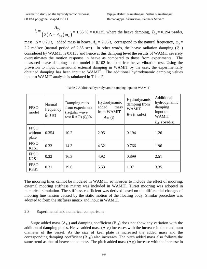
The experimental and numerical comparison of the heave RAO of FPSO with three
different widths of keel plates and 0.1 m wide skirt plate, and without damping plate (FPSO)
obtained from the experiments is shown in Fig. 6. For all the above model variation, the
numerical prediction is found to be good. The heave peak frequency shifts towards higher
frequency with the addition of keel and skirt plates. The peak heave RAO occurred at ω* = 0.56,
0.61, 0.71 and 0.71 for FPSO without damping plate, FPSO with 0.1m wide keel 0.1 m wide
skirt plate, FPSO with 0.2m wide keel 0.1 m wide skirt plate and FPSO with 0.3m wide keel 0.1
m wide skirt plate, respectively. The maximum RAO of FPSO K1S1 is 1.67 m/m @ ω* = 0.61,
which is significantly lower than for FPSO without damping plate of the order of 38.83 %. The
maximum heave RAO for the FPSO K2S1 model is 1.59 m/m @ ω* = 0.71; and for the FPSO
K3S1 model is 1.27 m/m @ ω* = 0.71. Compared to FPSO without damping plate, the reduction
in maximum heave response magnitude is 41.76 % and 53.48 % for FPSO K2S1 and FPSO
K3S1, respectively. The reduction in maximum RAO with the addition of keel and skirt plates is
due to the increase of damping.
0
0.5
1
1.5
2
2.5
3
0.2 0.5 0.8 1.1 1.4 1.7 2
Heav
e R
AO
(m
/m)
ω²B/2g
Experiment Numerical
FPSO
FPSO K1S1
FPSO K2S1
FPSO K3S1
Fig. 6 Comparison of heave RAO for FPSO with different width of keel and skirt plate
3. PARAMETRIC STUDY
Case study was carried out by changing the radius of the inlet opening, and moonpool area.
The study was carried out numerically for three models namely FPSO K1S1, FPSO K2S1 and
FPOS K3S1. Radius of inlet pipe and moonpool in the basic model are 0.2m and 0.5m,
respectively. First parametric study was carried out by varying the inlet pipe radius from 0.3 to
0.5m and the moon pool radius was kept as constant 0.5m. Second parametric study was carried
out by varying the Moonpool radius from 0.2 to 0.8m and the inlet radius was kept as constant

Parametric study on the hydrodynamic response Vijayalakshmi Ramalingam, Sathia Ramalingam,
Of DSI polygonal shaped FPSO Ramanagopal Srinivasan, Panneer Selvam
101
0.2 m. The different combinations of inlet pipe and moonpool radius adopted are given in Table
3. Multisurf model of FPSO K1S1 with 0.3 and 0.5m inlet radius is shown in Fig.7 and Fig.8
respectively. The Multisurf model and input files are generated, then the WAMIT analysis has
been carried out and the response of the model was evaluated. The salient results and discussion
of the parametric study are discussed below.
Table 3 combinations of inlet and moon pool opening
PARAMETRIC STUDY
FPSO WITH DIFFERENT
INLET RADIUS
(FPSO K1S1, FPSOK2S1, FPSO
K3S1)
FPSO WITH DIFFERENT
MOONPOOL RADIUS
(FPSO K1S1, FPSOK2S1, FPSO K3S1)
Radius of
inlet
Radius of Moon
pool Radius of inlet
Radius of
Moon pool
0.2 m 0.5 m 0.2 m 0.2 m
0.3 m 0.5 m 0.2 m 0.3 m
0.4 m 0.5 m 0.2 m 0.4 m
0.5 m 0.5 m 0.2 m 0.5 m
0.2 m 0.6 m
0.2 m 0.7 m
0.2 m 0.8 m
Fig. 7 FPSO with 0.3m inlet radius Fig. 8 FPSO with 0.5m inlet radius
Vijayalakshmi Ramalingam, Sathia Ramalingam, Parametric study on the hydrodynamic response
Ramanagopal Srinivasan, Panneer Selvam Of DSI polygonal shaped FPSO
102
4. RESULT AND DISCUSSION
4.1 Inlet radius
Parametric study was carried out for FPSO model fitted with different width of keel and skirt
plates for four different inlet pipe radii ranging from 0.2m to 0.5m using WAMIT. The variation
of surge and heave RAOs of FPSO with different inlet radius are discussed below.
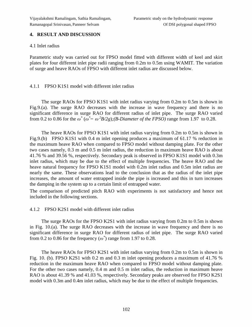
4.1.1 FPSO K1S1 model with different inlet radius
The surge RAOs for FPSO K1S1 with inlet radius varying from 0.2m to 0.5m is shown in
Fig.9.(a). The surge RAO decreases with the increase in wave frequency and there is no
significant difference in surge RAO for different radius of inlet pipe. The surge RAO varied
from 0.2 to 0.86 for the ω* (ω*= ω 2B/2g);(B-Diameter of the FPSO) range from 1.97 to 0.28.
The heave RAOs for FPSO K1S1 with inlet radius varying from 0.2m to 0.5m is shown in
Fig.9.(b) FPSO K1S1 with 0.4 m inlet opening produces a maximum of 61.17 % reduction in
the maximum heave RAO when compared to FPSO model without damping plate. For the other
two cases namely, 0.3 m and 0.5 m inlet radius, the reduction in maximum heave RAO is about
41.76 % and 39.56 %, respectively. Secondary peak is observed in FPSO K1S1 model with 0.3m
inlet radius, which may be due to the effect of multiple frequencies. The heave RAO and the
heave natural frequency for FPSO K1S1 model with 0.2m inlet radius and 0.5m inlet radius are
nearly the same. These observations lead to the conclusion that as the radius of the inlet pipe
increases, the amount of water entrapped inside the pipe is increased and this in turn increases
the damping in the system up to a certain limit of entrapped water.
The comparison of predicted pitch RAO with experiments is not satisfactory and hence not
included in the following sections.
4.1.2 FPSO K2S1 model with different inlet radius
The surge RAOs for the FPSO K2S1 with inlet radius varying from 0.2m to 0.5m is shown
in Fig. 10.(a). The surge RAO decreases with the increase in wave frequency and there is no
significant difference in surge RAO for different radius of inlet pipe. The surge RAO varied
from 0.2 to 0.86 for the frequency (ω*) range from 1.97 to 0.28.
The heave RAOs for FPSO K2S1 with inlet radius varying from 0.2m to 0.5m is shown in
Fig. 10. (b). FPSO K2S1 with 0.2 m and 0.3 m inlet opening produces a maximum of 41.76 %
reduction in the maximum heave RAO when compared to FPSO model without damping plate.
For the other two cases namely, 0.4 m and 0.5 m inlet radius, the reduction in maximum heave
RAO is about 41.39 % and 41.03 %, respectively. Secondary peaks are observed for FPSO K2S1
model with 0.3m and 0.4m inlet radius, which may be due to the effect of multiple frequencies.
Parametric study on the hydrodynamic response Vijayalakshmi Ramalingam, Sathia Ramalingam,
Of DSI polygonal shaped FPSO Ramanagopal Srinivasan, Panneer Selvam
103
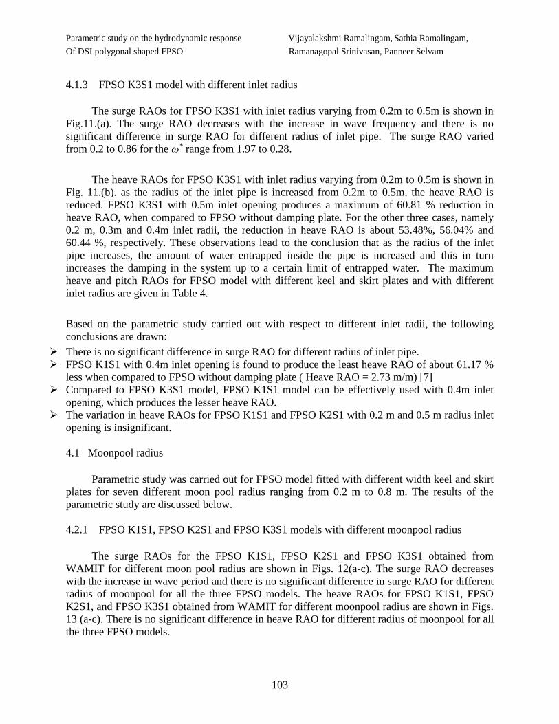
4.1.3 FPSO K3S1 model with different inlet radius
The surge RAOs for FPSO K3S1 with inlet radius varying from 0.2m to 0.5m is shown in
Fig.11.(a). The surge RAO decreases with the increase in wave frequency and there is no
significant difference in surge RAO for different radius of inlet pipe. The surge RAO varied
from 0.2 to 0.86 for the ω* range from 1.97 to 0.28.
The heave RAOs for FPSO K3S1 with inlet radius varying from 0.2m to 0.5m is shown in
Fig. 11.(b). as the radius of the inlet pipe is increased from 0.2m to 0.5m, the heave RAO is
reduced. FPSO K3S1 with 0.5m inlet opening produces a maximum of 60.81 % reduction in
heave RAO, when compared to FPSO without damping plate. For the other three cases, namely
0.2 m, 0.3m and 0.4m inlet radii, the reduction in heave RAO is about 53.48%, 56.04% and
60.44 %, respectively. These observations lead to the conclusion that as the radius of the inlet
pipe increases, the amount of water entrapped inside the pipe is increased and this in turn
increases the damping in the system up to a certain limit of entrapped water. The maximum
heave and pitch RAOs for FPSO model with different keel and skirt plates and with different
inlet radius are given in Table 4.
Based on the parametric study carried out with respect to different inlet radii, the following
conclusions are drawn:
There is no significant difference in surge RAO for different radius of inlet pipe.
FPSO K1S1 with 0.4m inlet opening is found to produce the least heave RAO of about 61.17 %
less when compared to FPSO without damping plate ( Heave RAO = 2.73 m/m) [7]
Compared to FPSO K3S1 model, FPSO K1S1 model can be effectively used with 0.4m inlet
opening, which produces the lesser heave RAO.
The variation in heave RAOs for FPSO K1S1 and FPSO K2S1 with 0.2 m and 0.5 m radius inlet
opening is insignificant.
4.1 Moonpool radius
Parametric study was carried out for FPSO model fitted with different width keel and skirt
plates for seven different moon pool radius ranging from 0.2 m to 0.8 m. The results of the
parametric study are discussed below.
4.2.1 FPSO K1S1, FPSO K2S1 and FPSO K3S1 models with different moonpool radius
The surge RAOs for the FPSO K1S1, FPSO K2S1 and FPSO K3S1 obtained from
WAMIT for different moon pool radius are shown in Figs. 12(a-c). The surge RAO decreases
with the increase in wave period and there is no significant difference in surge RAO for different
radius of moonpool for all the three FPSO models. The heave RAOs for FPSO K1S1, FPSO
K2S1, and FPSO K3S1 obtained from WAMIT for different moonpool radius are shown in Figs.
13 (a-c). There is no significant difference in heave RAO for different radius of moonpool for all
the three FPSO models.
Vijayalakshmi Ramalingam, Sathia Ramalingam, Parametric study on the hydrodynamic response
Ramanagopal Srinivasan, Panneer Selvam Of DSI polygonal shaped FPSO
104
Based on the parametric study carried out with respect to different moonpool radius, the
following conclusions are drawn: There is no significant difference in surge RAOs for different
moon pool radius of FPSO. However the heave RAO’s showed a marginal difference for the
wave period near the resonant period.
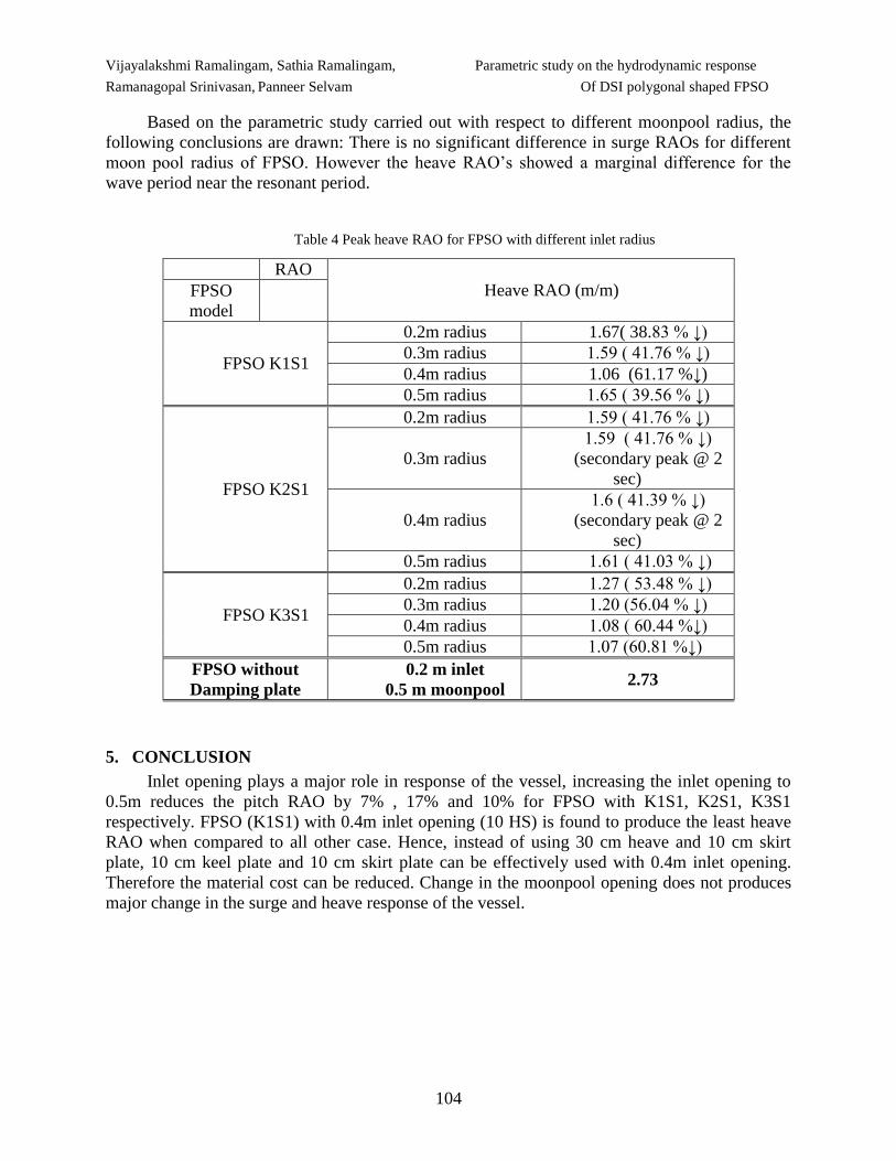
Table 4 Peak heave RAO for FPSO with different inlet radius
RAO
Heave RAO (m/m) FPSO
model
FPSO K1S1
0.2m radius 1.67( 38.83 % ↓)
0.3m radius 1.59 ( 41.76 % ↓)
0.4m radius 1.06 (61.17 %↓)
0.5m radius 1.65 ( 39.56 % ↓)
FPSO K2S1
0.2m radius 1.59 ( 41.76 % ↓)
0.3m radius
1.59 ( 41.76 % ↓)
(secondary peak @ 2
sec)
0.4m radius
1.6 ( 41.39 % ↓)
(secondary peak @ 2
sec)
0.5m radius 1.61 ( 41.03 % ↓)
FPSO K3S1
0.2m radius 1.27 ( 53.48 % ↓)
0.3m radius 1.20 (56.04 % ↓)
0.4m radius 1.08 ( 60.44 %↓)
0.5m radius 1.07 (60.81 %↓)
FPSO without
Damping plate
0.2 m inlet
0.5 m moonpool 2.73
5. CONCLUSION
Inlet opening plays a major role in response of the vessel, increasing the inlet opening to
0.5m reduces the pitch RAO by 7% , 17% and 10% for FPSO with K1S1, K2S1, K3S1
respectively. FPSO (K1S1) with 0.4m inlet opening (10 HS) is found to produce the least heave
RAO when compared to all other case. Hence, instead of using 30 cm heave and 10 cm skirt
plate, 10 cm keel plate and 10 cm skirt plate can be effectively used with 0.4m inlet opening.
Therefore the material cost can be reduced. Change in the moonpool opening does not produces
major change in the surge and heave response of the vessel.

Parametric study on the hydrodynamic response Vijayalakshmi Ramalingam, Sathia Ramalingam,
Of DSI polygonal shaped FPSO Ramanagopal Srinivasan, Panneer Selvam
105
0
0.2
0.4
0.6
0.8
1
1.2
0.2 0.5 0.8 1.1 1.4 1.7 2
Su
rge R
AO
(m
/m)
ω²B/2g
FPSO K1S1
0.2 m
0.3 m
0.4 m
0.5 m
0
0.3
0.6
0.9
1.2
1.5
1.8
0.2 0.5 0.8 1.1 1.4 1.7 2
Heav
e R
AO
(m
/m)
ω²B/2g
FPSO K1S1
0.2m
0.3m
0.4m
0.5m
Fig.9 (a) Fig.9 (b)
Fig.9 Surge and heave RAO for FPSO K1S1 model with different inlet radii
0
0.2
0.4
0.6
0.8
1
1.2
0.2 0.5 0.8 1.1 1.4 1.7 2
Su
rge R
AO
(m
/m)
ω²B/2g
FPSO K2S1
0.2 m
0.3 m
0.4 m
0.5 m
0
0.3
0.6
0.9
1.2
1.5
1.8
0.2 0.5 0.8 1.1 1.4 1.7 2
Heav
e R
AO
(m
/m)
ω²B/2g
FPSO K2S1
0.2m
0.3m
0.4m
0.5m
Fig.10 (a) Fig.10 (b)
Fig.10. Surge and heave RAO for FPSO K2S1 model with different inlet radius
0
0.2
0.4
0.6
0.8
1
1.2
0.2 0.5 0.8 1.1 1.4 1.7 2
Su
rge R
AO
(m
/m)
ω²B/2g
FPSO K3S1
0.2 m
0.3 m
0.4 m
0.5 m
0
0.2
0.4
0.6
0.8
1
1.2
1.4
0.2 0.5 0.8 1.1 1.4 1.7 2
Hea
ve
RA
O (
m/m
)
ω²B/2g
FPSO K3S1
0.2 m
0.3 m
0.4 m
0.5 m
Fig.11 (a) Fig. 11 (b)
Fig.11 Surge and heave RAO for FPSO K3S1 model with different inlet radius

Vijayalakshmi Ramalingam, Sathia Ramalingam, Parametric study on the hydrodynamic response
Ramanagopal Srinivasan, Panneer Selvam Of DSI polygonal shaped FPSO
106
0.0
0.2
0.4
0.6
0.8
1.0
0.0 0.5 1.0 1.5 2.0 2.5
Su
rge R
AO
(m
/m)
ω 2B/2g
FPSO K1S10.2m moon pool radius
0.3 m moon pool radius
0.4 m monn pool radius
0.5 m moon pool radius
0.6 m moon pool radius
0.7 m moon pool radius
0.8m moon pool radius
0.0
0.2
0.4
0.6
0.8
1.0
1.2
1.4
1.6
1.8
0.0 0.5 1.0 1.5 2.0 2.5
Hea
ve R
AO
(m
/m)
ω 2B/2g
FPSO K1S10.2m moon pool radius
0.3 m moon pool radius
0.4 m monn pool radius
0.5 m moon pool radius
0.6 m moon pool radius
0.7 m moon pool radius
0.8m moon pool radius
Fig. 12 (a) Fig. 13(a)
0.0
0.2
0.4
0.6
0.8
1.0
0.0 0.5 1.0 1.5 2.0 2.5
Su
rge R
AO
(m
/m)
ω 2B/2g
FPSO K2S10.2m moon pool radius
0.3 m moon pool radius
0.4 m monn pool radius
0.5 m moon pool radius
0.6 m moon pool radius
0.7 m moon pool radius
0.8m moon pool radius
0.0
0.2
0.4
0.6
0.8
1.0
1.2
1.4
1.6
1.8
0.0 0.5 1.0 1.5 2.0 2.5
Hea
ve R
AO
(m
/m)
ω 2B/2g
FPSO K2S1
0.2m moon pool radius
0.3 m moon pool radius
0.4 m monn pool radius
0.5 m moon pool radius
0.6 m moon pool radius
0.7 m moon pool radius
0.8m moon pool radius
Fig. 12(b) Fig. 13 (b)
0.0
0.2
0.4
0.6
0.8
1.0
1.2
1.4
0.0 0.5 1.0 1.5 2.0 2.5
Hea
ve R
AO
(m
/m)
ω 2B/2g
0.2 m moon pool radius
0.3 m moon pool radius
0.4 m monn pool radius
0.5 m moonpool radius
0.6 m moon pool radius
0.7 m moon pool radius
0.8 m moon pool radius
0.0
0.2
0.4
0.6
0.8
1.0
0.0 0.5 1.0 1.5 2.0 2.5
Su
rge R
AO
(m
/m)
ω 2B/2g
FPSO K3S10.2m moon pool radius
0.3 m moon pool radius
0.4 m monn pool radius
0.5 m moon pool radius
0.6 m moon pool radius
0.7 m moon pool radius
0.8m moon pool radius
Fig. 12 (c) Fig. 13(c)
Fig.12 Surge RAO for FPSO model with Fig.13 Heave RAO for FPSO
Different moonpool radii with different moonpool radii
Parametric study on the hydrodynamic response Vijayalakshmi Ramalingam, Sathia Ramalingam,
Of DSI polygonal shaped FPSO Ramanagopal Srinivasan, Panneer Selvam
107
6. REFERENCES
[1] Bin, B.L., Ou, J. P., Teng, B., 2011, “Numerical investigation of damping effects on coupled heave and
pitch motion of an innovative deep draft multi spar,” Journal of marine science and technology, Vol 19,
No-2, pp. 231-244.
[2] Fan, M., Li, D., Liu, T., Ran, A., Wei, Y., 2010, “An Innovative Synthetic Mooring Solution for an
Octagonal FPSO in Shallow Waters,” Proceedings of ASME 2010 29th International Conference on
Ocean, Offshore and Arctic Engineering OMAE, June.
[3] Goncalves, R.T., Matsumoto, F.T., Malta, E.B., Madeiros, H.F., Nishimoto, K., 2010, “Conceptual
design of Monocolumn production and storage with dry tree capability,” Journal of offshore mechanics
and arctic engineering, Volume 132, 4031(1-12). http://dx.doi:10.1115/1.4001429.
[4] Goncalves, R.T., Rosetti, G.F., Fujarra, A.L., Nishimoto, K., 2010, “Mitigation of vortex induced
motion on a monocolumn platform: forces and movements,” Journal of offshore mechanics and arctic
engineering, vol. 132, 41102(1-16). http://dx.doi:10.1115/1.4001440.
[5] Koh, J.H., Cho, I. H., 2011, “Motion response of a circular cylinder with a heave plate in waves,”
Proceeding of 21st International offshore and polar engineering conference”. June 19-24.
[6] Malta, E. B., Cueva, M., Nishimoto, K., Gonçalves, R. T., Masetti, I., 2006, “Numerical Moonpool
Modeling,” Proceedings of the 25th International Conference on Offshore Mechanics and Arctic
Engineering, Hamburg, Germany, OMAE2006- 92456.
[7] Masetti, I.Q., Costa, A.P., Matter, G.B., Barreria, R.A., Sphaier, S.H., 2007, “Effect of skirts on the
behaviour of monocolumn structure in wave,” International Conference on Offshore Mechanics and
Arctic Engineering, OMAE 2007, pp. 293-300.
[8] Shen, W., Tang, Y., Liu, L., 2010, “Study on the hydrodynamic characteristics for heave plate structure
of truss spar, Journal of offshore mechanics and arctic engineering”. OMAE-21166, pp. 983-988.
http://dx.doi:10.1115/OMAE2010-21166.
[9] Thiagarajan, K. P., Datta, I., Ran, A. Z., Tao, L., Halkyard, J. E., 2002, “Influence of heave Plate
Geometry on the Heave Response of Classic Spar,” Proceedings of the 22nd International Conference
Offshore Mechanics and Arctic Engineering, Oslo, Norway, OMAE 2002-28350.
[10] Torres, F., Cueva, M., Malta, E. B., Nishimoto, K., Ferreira, M. D., 2004, “Study of Numerical
Modeling of Moonpool as Minimization Device of Monocolumn Hull,” Proceedings of the 24th
International Conference Off- shore Mechanics and Arctic Engineering, Vancouver, Canada, Paper No.
OMAE 2004-51540.
[11] Torres, G.S., Alho, T.P., Sales, S., Sphaier, H., Nishimoto, K., 2008, “Experimental and numerical
analysis of the behavior of a monocolumn with moonpool,” Proceeding of 27th international
conference of offshore mechanics and arctic engineering, 3, 291-300.
[12] VIjayalakshmi, R., Panneerselvam, R., Sannasiraj, S.A., Nagan srinivasan., 2008, “Experimental
Investigations on a Non-ship Shaped FPSO Vessel,” International Society of Off shore and Polar
Engineering conference, Pacoms, Bangkok, Thailand, ISOPE-P-08-013
[13] VIjayalakshmi, R., Panneerselvam, R., Sannasiraj, S.A., 2009, “Numerical Analysis of non-ship hull
shaped FPSO vessel,” International Conference of Ocean Engineering, February, 271.
[14] Vijayalakshmi, R., Panneerselvam, R., 2012, “Hydrodynamic response of a non-ship hull shaped FPSO
vessel with damping plates,” Journal of marine science and technology, June, Vol.17, Issue 2, pp.187-
202. http://dx.doi: 10.1007/s00773-012-0162-5.
Submitted: 09.12.2016.
Accepted: 22.03.2017.
Vijayalakshmi Ramalingam, [email protected]
Ramanagopal Srinivasan
Department of Civil Engineering, SSN College of Engineering, Tamilnadu, India.
Sathia Ramalingam
Department of Civil Engineering, Jeppiar College of Engineering, Tamilnadu, India.
Panneer Selvam
Department of Ocean Engineering, Indian Institute of Technology Madras Tamilnadu, India


![[AMOROSI] Parametric Study on Seismic Ground Response by Finite Element Modelling](https://img.pdfslide.us/doc/110x75/577cc50e1a28aba7119b2298/amorosi-parametric-study-on-seismic-ground-response-by-finite-element-modelling.jpg)