Embed Size (px)
Citation preview
Parametric study of the absorption cross sectionfor a moderately conducting thin cylinder
Kristan P. Gurton and Charles W. Bruce
Asystem has been developed tomeasure the absorption cross section for a single carbon fiber at 35 GHz asa function of length, orientation, and diameter. Typical lengths of the fibers considered ranged from 1 to20 mm, and diameters ranged from 3 to 8 µm. The results were compared with the modified integralequation calculations of Waterman and Pedersen that describe the scattering and absorption behavior fora wire of finite length and conductivity. Good agreement was found for all lengths, orientations, anddiameters studied.Key words: Absorption, optical properties, carbon fiber, thin cylinder, millimeter wavelength.
1. Introduction
Recently there has been much interest in electromag-netic extinction as a result of both naturally occurringand artificial fibrous aerosols.1–4 As pointed out byBruce and colleagues,2–4 the electromagnetic model-ing of fiberlike particles such as soot is very difficult,especially for large size parameters. Such particlesare typically characterized as moderately conducting,where the primarymechanism for extinction 1atmicro-wave frequencies2 is absorption. A thin cylinder isthe simplest type of fibrous particle whose electromag-netic properties can be readily computed.5–7 Al-though there are several analytic and numeric tech-niques available, experimental analogs have beenquite lacking, and the few that do exist are restrictedto the scattering component only.8–10Bruce et al.’s first study involving thin fibers mea-
sured the variability of the extinction cross section asa function of conductivity 1as well as interparticlecoupling effects2 for a two-dimensional array. Thosemeasurements, as were the measurements in thispaper, were made at a wavelength of 0.86 cm.11Agreement with computed values was within theexperimental error of the measurement. In a suc-ceeding study both carbon and metallic fibers wererandomly dispersed in a closed chamber for frequency
The authors are with the Department of Physics, New MexicoState University, Box 30001 Department 3D, Las Cruces, NewMexico 88003-0001.Received 25 May 1994; revised manuscript received 1 November
1994.0003-6935@95@152822-07$06.00@0.
r 1995 Optical Society of America.
2822 APPLIED OPTICS @ Vol. 34, No. 15 @ 20 May 1995
scans about the primary resonance.12 Although themeasurements at resonance confirmed the computedenhancement in extinction that was due to scatteringby the metallic fibers 1relative to the absorption of thecarbon fibers2, the angular and the length distribu-tions served to dilute the spectral features. It be-came apparent that to understand the detailed behav-ior of such particles, a measurement had to bedeveloped to make explicit both the angular and thespectral dependencies of a single fiber.The purpose of this study was to develop an experi-
mental method capable of measuring the electromag-netic absorption that was due to a single moderatelyconducting aerosol particle as a function of size,composition, and orientation with respect to the inci-dent electric field. Although the device presentedhere was designed to investigate the absorptive prop-erties for particles within a certain range of sizeparameters, there exists no fundamental reason whythe technique could not be scaled accordingly toencompass practically any size parameter of interest.Because of the nature of the experiment, only par-ticles with good absorptive characteristics at millime-ter wavelengths were considered. The first suchparticle considered was a thin carbon fiber. Allmeasurements presented here were compared withelectromagnetic computation conducted by Water-man and Pedersen. They used an analytic methodthat is outlined in Ref. 5 and is based on a modifiedintegral equation formalism.
2. Theory
It has long been established that the degree to whicha substance absorbs electromagnetic energy is relatedto the thermal change of the absorber.13–16 Thincarbon fibers proved to be an ideal type of particle for
application because of their extremely fast thermalresponse 1when irradiated2 and strong absorption atmillimeter wavelengths.The approach taken here is based on the simple
premise that a particle that is absorbing electromag-netic radiation experiences a proportional increase intemperature. After the temperature of the absorb-ing particle has reached a steady state, any heatgenerated within the particle will be conducted to thesurrounding gas. If the particle is enclosed in a fixedvolume, a change in pressure will result. This time-dependent change in pressure is directly related tothe absorption process.For the specific system used here this change in
pressure reads
1dDp
dt 2 5 1dDp
dt 2abs 2 51dDp
dt 2drift 1 1dDp
dt 2loss 1 1dDp
dt 2leak6.112
The first term on the right-hand side of Eq. 112represents the change in rate of the differentialpressure between two identical equally irradiatedsealed chambers that results solely from the absorb-ing particle. One chamber contains the particle andis termed the absorption chamber, and the other isempty and serves as a reference.The terms 1dDp@dt2drift and 1dDp@dt2loss represent
changes in the rate of the total differential pressurebecause of ambient thermal drift of the system andlosses resulting from heat conduction to the chamberwalls, respectively. The term 1dDp@dt2leak representsa signal loss rate that results from a variable leakvalve. This valve is placed between the two cham-bers and is used to reduce any slowly varying baromet-ric or thermal drift that may be present. It is shownbelow that all three of the loss mechanisms describedabove can be greatly reduced or eliminated by theproper design and operation of the device.During irradiation, the particle is heated at a rate
given by
dQ
dt5 sabsIrad, 122
where sabs is the absorption cross section of theparticle and Irad represents the irradiance that isincident upon the particle.After the particle has reached a steady state, the
heat energy is transferred to the surrounding gas 1inthis case air at atmospheric pressure2 at a rate givenby
dQ
dt5 nacn3dTdt 4air, 132
which results in a change in temperature per unittime, 3dT@dt4air. Here na represents the number ofmoles and cn is the molar specific heat of air atconstant volume. Volume averages are denoted by3 4. It has been assumed that the heating of the
particle is moderate enough so that any energy lossdue to radiation effects can be ignored.Because the air within the chambers can be as-
sumed to be an ideal gas,
1dDp
dt 2abs 5 rR3dTdt 4air, 142
where r and R are the density and the specific gasconstant of air, respectively.By equating the heat generated by the particle with
the heat absorbed by the surrounding gas and usingEq. 142, one may obtain the following relation:
sabs 5Vcn
RIrad 1dDp
dt 2abs, 152
where V represents the total volume in which theparticle is enclosed. Equation 152 shows that thetime-dependent change in pressure is proportional tothe total absorption cross section of the particle.
3. Experimental Apparatus
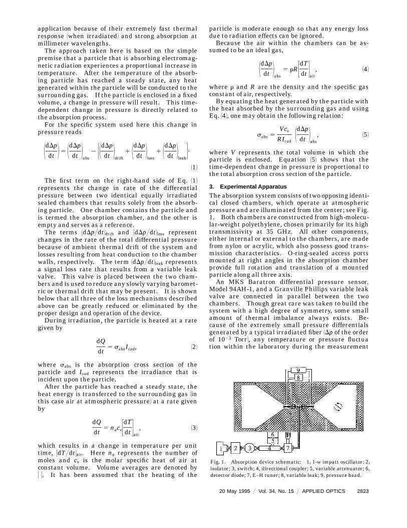
The absorption system consists of two opposing identi-cal closed chambers, which operate at atmosphericpressure and are illuminated from the center; see Fig.1. Both chambers are constructed from high-molecu-lar-weight polyethylene, chosen primarily for its hightransmissivity at 35 GHz. All other components,either internal or external to the chambers, are madefrom nylon or acrylic, which also possess good trans-mission characteristics. O-ring-sealed access portsmounted at right angles in the absorption chamberprovide full rotation and translation of a mountedparticle along all three axis.An MKS Baratron differential pressure sensor,
Model 94AH-1, and a Granville Phillips variable leakvalve are connected in parallel between the twochambers. Though great care was taken to build thesystem with a high degree of symmetry, some smallamount of thermal imbalance always exists. Be-cause of the extremely small pressure differentialsgenerated by a typical irradiated fiber 1Dp of the orderof 1023 Torr2, any temperature or pressure fluctuation within the laboratory during the measurement
Fig. 1. Absorption device schematic: 1, 1-w impatt oscillator; 2,isolator; 3, switch; 4, directional coupler; 5, variable attenuator; 6,detector diode; 7, E–H tuner; 8, variable leak; 9, pressure head.
20 May 1995 @ Vol. 34, No. 15 @ APPLIED OPTICS 2823
would result in a slowly varying drift signal1dDp@dt2drift. The variable leak rate is adjusted toreduce this drift. To avoid any appreciable loss insignal, the leak rate is kept much smaller than that ofthe actual signal rate.The ambient drift is reduced further by the use of a
specially machined block of aluminum connected be-tween the two chambers. This block serves as athroughput for the pressure assembly and reducesany temperature gradients that may develop becauseof separate connections. This assembly is attachedto the chambers through two nylon bulkhead connec-tors. All metallic portions of the pressure assemblyare shielded by microwave-absorbing material to pre-vent any spurious scattering of microwave radiationback to the chambers.The microwave system consists of the following
components in series: a Hughes 1-W impact ava-lanche and transit time oscillator 1the 35-GHz source2,a microwave isolator, a manual switch, a 20-dBdirectional coupler, and an E–H tuner 1the tuner isused to minimize the impedance mismatch betweenthe microwave system and the radiators2. Referencepower is measured 1relatively2 by the use of a solid-state detector diode that is mounted in the forwarddirection of the coupler. At the end of the microwavesystem, power is evenly split between the two cham-bers by means of a waveguide tee. Polyethylenewaveguide output windows, 0.005-cm-thick, eachwitha 0.7-dB insertion loss, are mounted between theflanges that precede the output horns and produce thenecessary pressure seals that isolate the two cham-bers.Attempts to create an approximately plane wave
within the enclosures proved most challenging.Commercial horns were considered but were too largeand required that the particle be placed an unreason-able distance away to satisfy the far-field criteria.Asecond horn consideredwas an open-endwaveguide.But this type of radiator lacked the directivity re-quired. The more nearly optimal solution was aspecially flared piece of WR-28 waveguide. The twonarrow sides of the guide were milled off approxi-mately 1 cm from the end of the guide. The remain-ing two sides were flared out 10° and copper plateswere soldered in place with silver. The result was asmall square-aperture sectoral-type horn. This hornpossessed the desired linear polarization, directivity,and efficiency needed, while minimizing the distanceneeded to achieve an approximate plane wave.A conical geometry was chosen for the internal
cavity of the chambers to minimize volume and thusincrease the response of the system. The half-angleof the cone was chosen to be 50°. At this angle theelectric-field intensity at the internal surfaces wasapproximately 12 dB down on the main lobe of theradiator. The overall external length and the diam-eter of the system were 45.72 and 20.32 cm, respec-tively. This allowed for sufficient distance from theradiators to the face plates that terminated the cones.Any reflected energy from the face plates back to the
2824 APPLIED OPTICS @ Vol. 34, No. 15 @ 20 May 1995
particle was negligible when compared with that ofthe forwardwave. Fresnel calculations affirmed this.Efforts were made to minimize reflections resultingfrom the side and the back lobes of the radiators.A Teflon wedge was placed behind the radiator andserved to reduce these reflections. All other reflec-tions from the chamber surfaces to the particle regionwere negligible.During the development of the system, concerns
were raised about the internal geometry of the cham-bers; i.e., it might produce some form of depolariza-tion of the incident field. The polarization was testedby the rotation of a standard gain horn–power diodeassembly. These studies confirmed that the systempossessed a linear polarization to at least 40 dB.A thorough spatial mapping of the field intensity in
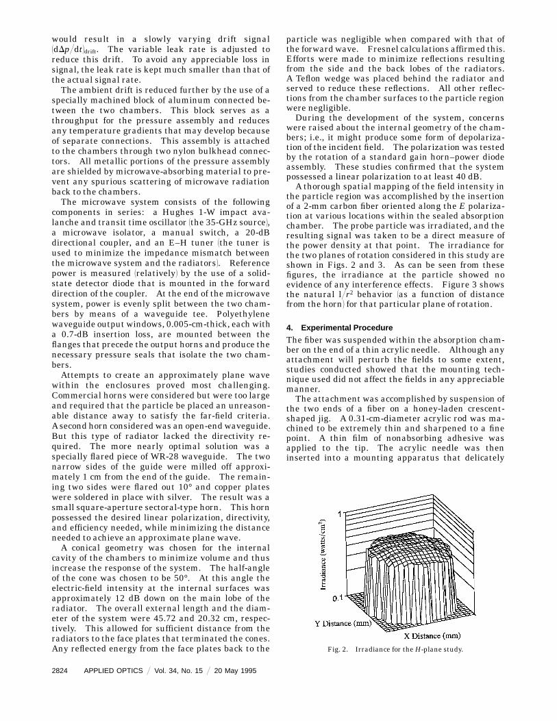
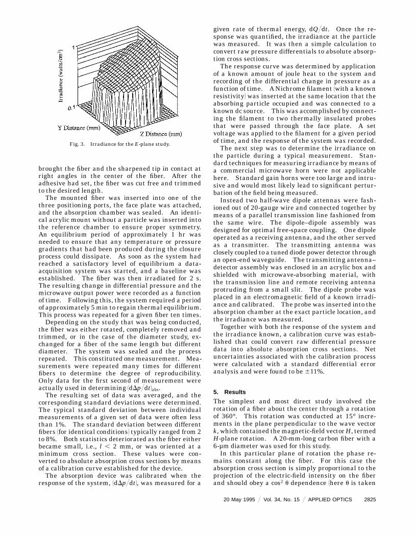
the particle region was accomplished by the insertionof a 2-mm carbon fiber oriented along the E polariza-tion at various locations within the sealed absorptionchamber. The probe particle was irradiated, and theresulting signal was taken to be a direct measure ofthe power density at that point. The irradiance forthe two planes of rotation considered in this study areshown in Figs. 2 and 3. As can be seen from thesefigures, the irradiance at the particle showed noevidence of any interference effects. Figure 3 showsthe natural l@r2 behavior 1as a function of distancefrom the horn2 for that particular plane of rotation.
4. Experimental Procedure
The fiber was suspended within the absorption cham-ber on the end of a thin acrylic needle. Although anyattachment will perturb the fields to some extent,studies conducted showed that the mounting tech-nique used did not affect the fields in any appreciablemanner.The attachment was accomplished by suspension of
the two ends of a fiber on a honey-laden crescent-shaped jig. A 0.31-cm-diameter acrylic rod was ma-chined to be extremely thin and sharpened to a finepoint. A thin film of nonabsorbing adhesive wasapplied to the tip. The acrylic needle was theninserted into a mounting apparatus that delicately
Fig. 2. Irradiance for theH-plane study.
brought the fiber and the sharpened tip in contact atright angles in the center of the fiber. After theadhesive had set, the fiber was cut free and trimmedto the desired length.The mounted fiber was inserted into one of the
three positioning ports, the face plate was attached,and the absorption chamber was sealed. An identi-cal acrylic mount without a particle was inserted intothe reference chamber to ensure proper symmetry.An equilibrium period of approximately 1 hr wasneeded to ensure that any temperature or pressuregradients that had been produced during the closureprocess could dissipate. As soon as the system hadreached a satisfactory level of equilibrium a data-acquisition system was started, and a baseline wasestablished. The fiber was then irradiated for 2 s.The resulting change in differential pressure and themicrowave output power were recorded as a functionof time. Following this, the system required a periodof approximately 5min to regain thermal equilibrium.This process was repeated for a given fiber ten times.Depending on the study that was being conducted,
the fiber was either rotated, completely removed andtrimmed, or in the case of the diameter study, ex-changed for a fiber of the same length but differentdiameter. The system was sealed and the processrepeated. This constituted onemeasurement. Mea-surements were repeated many times for differentfibers to determine the degree of reproducibility.Only data for the first second of measurement wereactually used in determining [email protected] resulting set of data was averaged, and the
corresponding standard deviations were determined.The typical standard deviation between individualmeasurements of a given set of data were often lessthan 1%. The standard deviation between differentfibers 1for identical conditions2 typically ranged from 2to 8%. Both statistics deteriorated as the fiber eitherbecame small, i.e., l , 2 mm, or was oriented at aminimum cross section. These values were con-verted to absolute absorption cross sections by meansof a calibration curve established for the device.The absorption device was calibrated when the
response of the system, 1dDp@dt2, was measured for a
Fig. 3. Irradiance for the E-plane study.
given rate of thermal energy, dQ@dt. Once the re-sponse was quantified, the irradiance at the particlewas measured. It was then a simple calculation toconvert raw pressure differentials to absolute absorp-tion cross sections.The response curve was determined by application
of a known amount of joule heat to the system andrecording of the differential change in pressure as afunction of time. ANichrome filament 1with a knownresistivity2 was inserted at the same location that theabsorbing particle occupied and was connected to aknown dc source. This was accomplished by connect-ing the filament to two thermally insulated probesthat were passed through the face plate. A setvoltage was applied to the filament for a given periodof time, and the response of the system was recorded.The next step was to determine the irradiance on
the particle during a typical measurement. Stan-dard techniques for measuring irradiance bymeans ofa commercial microwave horn were not applicablehere. Standard gain horns were too large and intru-sive and would most likely lead to significant pertur-bation of the field being measured.Instead two half-wave dipole attennas were fash-
ioned out of 20-gauge wire and connected together bymeans of a parallel transmission line fashioned fromthe same wire. The dipole–dipole assembly wasdesigned for optimal free-space coupling. One dipoleoperated as a receiving antenna, and the other servedas a transmitter. The transmitting antenna wasclosely coupled to a tuned diode power detector throughan open-end waveguide. The transmitting antenna–detector assembly was enclosed in an acrylic box andshielded with microwave-absorbing material, withthe transmission line and remote receiving antennaprotruding from a small slit. The dipole probe wasplaced in an electromagnetic field of a known irradi-ance and calibrated. The probe was inserted into theabsorption chamber at the exact particle location, andthe irradiance was measured.Together with both the response of the system and
the irradiance known, a calibration curve was estab-lished that could convert raw differential pressuredata into absolute absorption cross sections. Netuncertainties associated with the calibration processwere calculated with a standard differential erroranalysis and were found to be 611%.
5. Results
The simplest and most direct study involved therotation of a fiber about the center through a rotationof 360°. This rotation was conducted at 15° incre-ments in the plane perpendicular to the wave vectork, which contained themagnetic-field vectorH, termedH-plane rotation. A 20-mm-long carbon fiber with a6-µm diameter was used for this study.In this particular plane of rotation the phase re-
mains constant along the fiber. For this case theabsorption cross section is simply proportional to theprojection of the electric-field intensity on the fiberand should obey a cos2 u dependence 1here u is taken
20 May 1995 @ Vol. 34, No. 15 @ APPLIED OPTICS 2825
to be the angle between the fiber axis and H2. Theresulting curves of cross section versus angle 1for the360° rotation2 displayed a high degree of symmetry.This was further evidence that the field was reason-ably flat for this plane of rotation. Because of therepetitive form of the absorption cross section be-tween quadrants, only data for u 5 0 to 90° are shownhere; see Fig. 4.As can be seen in Fig. 4, the absorption cross section
that was measured closely approximates the cos2 udependence, as predicted. As mentioned above, con-cerns about depolarizing effects were partially ad-dressed during the development of the system butwere conductedwithout the face plates being attached.The results of this study confirmed that the polariza-tion of the incident field was still reasonably linear forthe sealed system. All error bars shown throughoutrepresent the propagated uncertainties inherent inthe calibration–measurement procedure.A second study was conducted to determine the
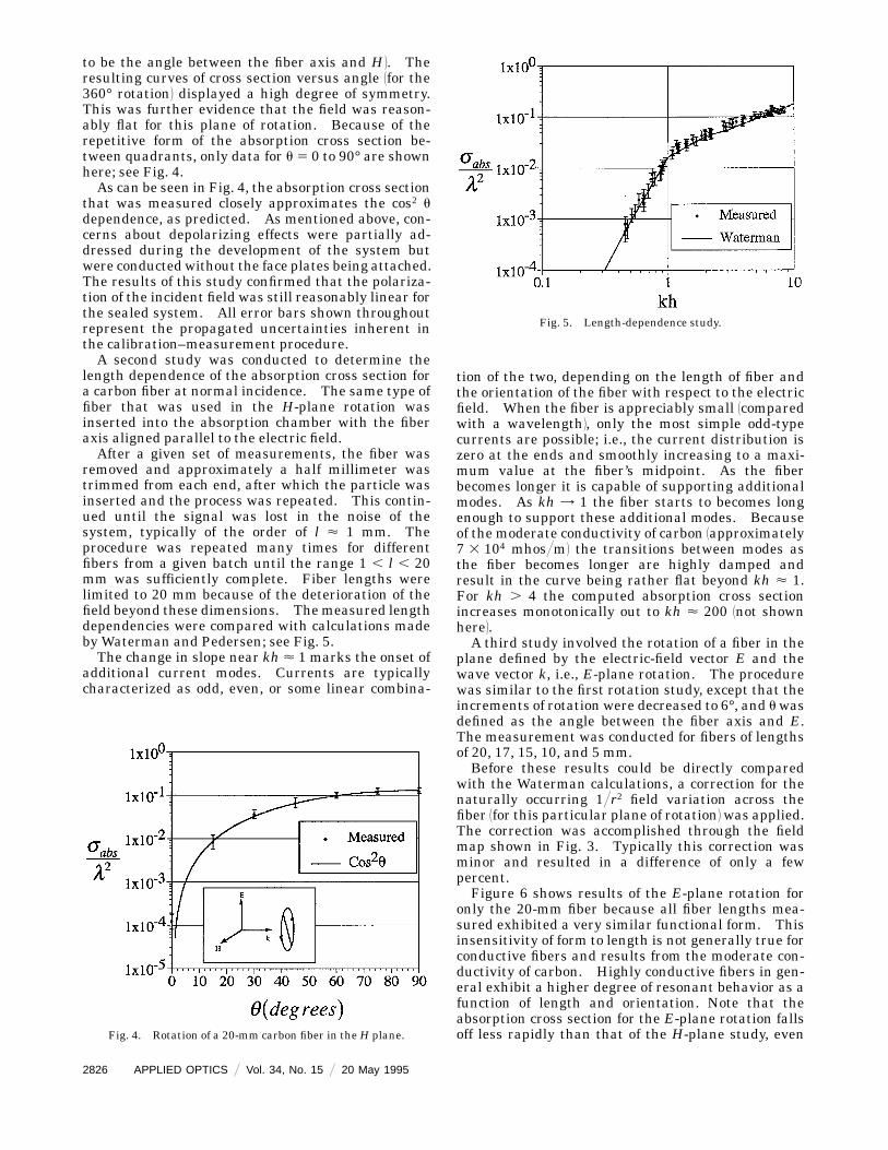
length dependence of the absorption cross section fora carbon fiber at normal incidence. The same type offiber that was used in the H-plane rotation wasinserted into the absorption chamber with the fiberaxis aligned parallel to the electric field.After a given set of measurements, the fiber was
removed and approximately a half millimeter wastrimmed from each end, after which the particle wasinserted and the process was repeated. This contin-ued until the signal was lost in the noise of thesystem, typically of the order of l < 1 mm. Theprocedure was repeated many times for differentfibers from a given batch until the range 1 , l , 20mm was sufficiently complete. Fiber lengths werelimited to 20 mm because of the deterioration of thefield beyond these dimensions. Themeasured lengthdependencies were compared with calculations madeby Waterman and Pedersen; see Fig. 5.The change in slope near kh < 1 marks the onset of
additional current modes. Currents are typicallycharacterized as odd, even, or some linear combina-
Fig. 4. Rotation of a 20-mm carbon fiber in theH plane.
2826 APPLIED OPTICS @ Vol. 34, No. 15 @ 20 May 1995
tion of the two, depending on the length of fiber andthe orientation of the fiber with respect to the electricfield. When the fiber is appreciably small 1comparedwith a wavelength2, only the most simple odd-typecurrents are possible; i.e., the current distribution iszero at the ends and smoothly increasing to a maxi-mum value at the fiber’s midpoint. As the fiberbecomes longer it is capable of supporting additionalmodes. As kh = 1 the fiber starts to becomes longenough to support these additional modes. Becauseof the moderate conductivity of carbon 1approximately7 3 104 mhos@m2 the transitions between modes asthe fiber becomes longer are highly damped andresult in the curve being rather flat beyond kh < 1.For kh . 4 the computed absorption cross sectionincreases monotonically out to kh < 200 1not shownhere2.A third study involved the rotation of a fiber in the
plane defined by the electric-field vector E and thewave vector k, i.e., E-plane rotation. The procedurewas similar to the first rotation study, except that theincrements of rotation were decreased to 6°, and uwasdefined as the angle between the fiber axis and E.The measurement was conducted for fibers of lengthsof 20, 17, 15, 10, and 5 mm.Before these results could be directly compared
with the Waterman calculations, a correction for thenaturally occurring 1@r2 field variation across thefiber 1for this particular plane of rotation2was applied.The correction was accomplished through the fieldmap shown in Fig. 3. Typically this correction wasminor and resulted in a difference of only a fewpercent.Figure 6 shows results of the E-plane rotation for
only the 20-mm fiber because all fiber lengths mea-sured exhibited a very similar functional form. Thisinsensitivity of form to length is not generally true forconductive fibers and results from the moderate con-ductivity of carbon. Highly conductive fibers in gen-eral exhibit a higher degree of resonant behavior as afunction of length and orientation. Note that theabsorption cross section for the E-plane rotation fallsoff less rapidly than that of the H-plane study, even
Fig. 5. Length-dependence study.
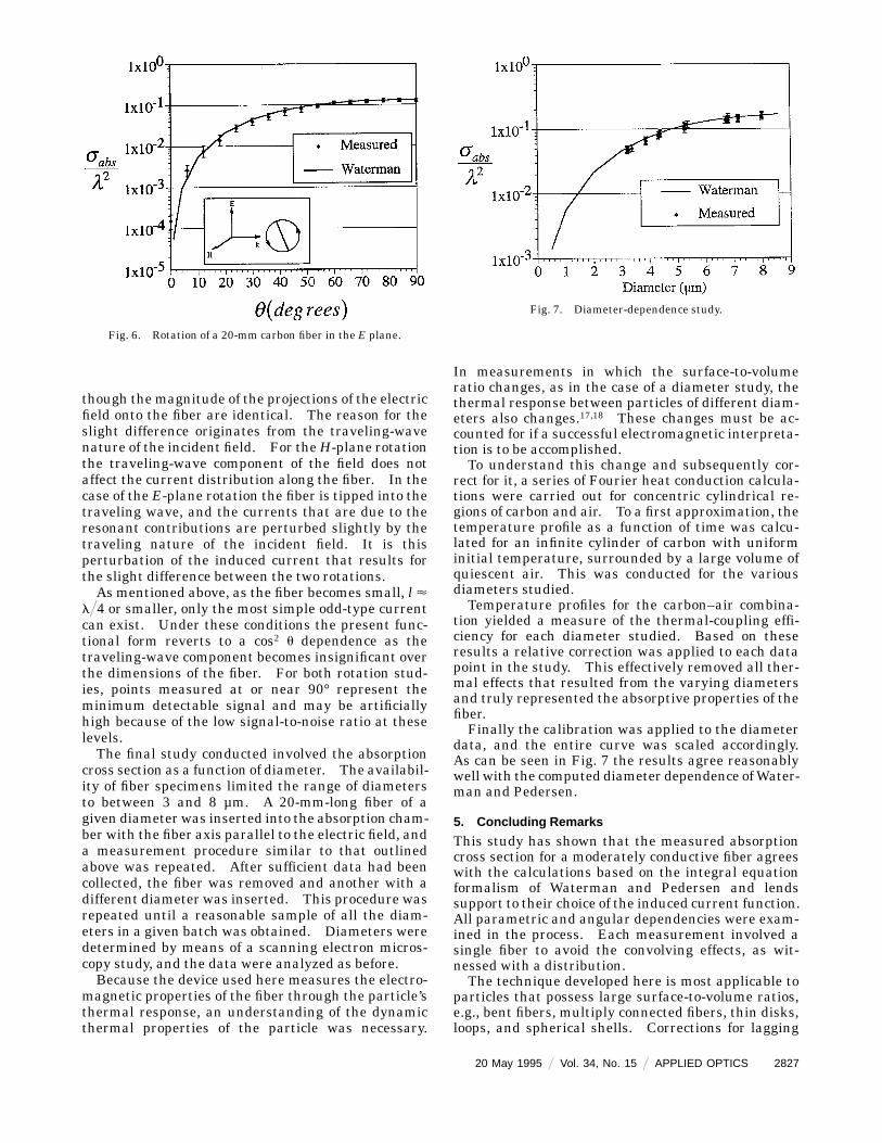
though the magnitude of the projections of the electricfield onto the fiber are identical. The reason for theslight difference originates from the traveling-wavenature of the incident field. For theH-plane rotationthe traveling-wave component of the field does notaffect the current distribution along the fiber. In thecase of the E-plane rotation the fiber is tipped into thetraveling wave, and the currents that are due to theresonant contributions are perturbed slightly by thetraveling nature of the incident field. It is thisperturbation of the induced current that results forthe slight difference between the two rotations.As mentioned above, as the fiber becomes small, l <
l@4 or smaller, only the most simple odd-type currentcan exist. Under these conditions the present func-tional form reverts to a cos2 u dependence as thetraveling-wave component becomes insignificant overthe dimensions of the fiber. For both rotation stud-ies, points measured at or near 90° represent theminimum detectable signal and may be artificiallyhigh because of the low signal-to-noise ratio at theselevels.The final study conducted involved the absorption
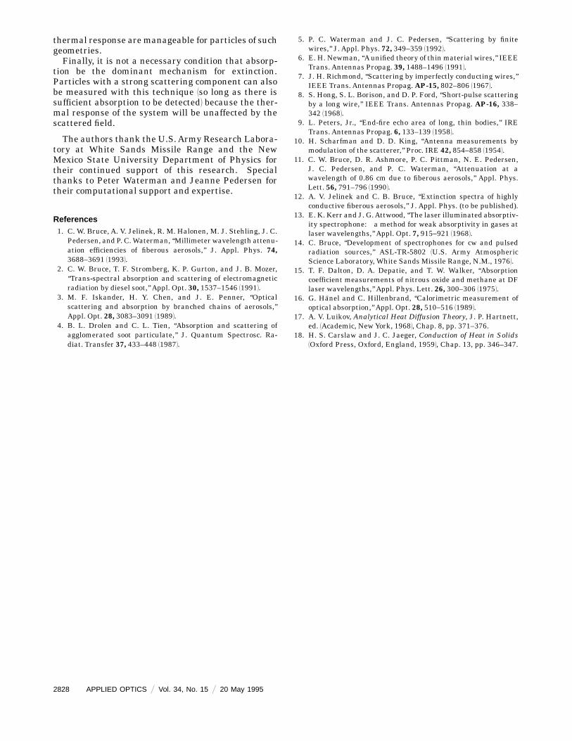
cross section as a function of diameter. The availabil-ity of fiber specimens limited the range of diametersto between 3 and 8 µm. A 20-mm-long fiber of agiven diameter was inserted into the absorption cham-ber with the fiber axis parallel to the electric field, anda measurement procedure similar to that outlinedabove was repeated. After sufficient data had beencollected, the fiber was removed and another with adifferent diameter was inserted. This procedure wasrepeated until a reasonable sample of all the diam-eters in a given batch was obtained. Diameters weredetermined by means of a scanning electron micros-copy study, and the data were analyzed as before.Because the device used here measures the electro-
magnetic properties of the fiber through the particle’sthermal response, an understanding of the dynamicthermal properties of the particle was necessary.
Fig. 6. Rotation of a 20-mm carbon fiber in the E plane.
In measurements in which the surface-to-volumeratio changes, as in the case of a diameter study, thethermal response between particles of different diam-eters also changes.17,18 These changes must be ac-counted for if a successful electromagnetic interpreta-tion is to be accomplished.To understand this change and subsequently cor-
rect for it, a series of Fourier heat conduction calcula-tions were carried out for concentric cylindrical re-gions of carbon and air. To a first approximation, thetemperature profile as a function of time was calcu-lated for an infinite cylinder of carbon with uniforminitial temperature, surrounded by a large volume ofquiescent air. This was conducted for the variousdiameters studied.Temperature profiles for the carbon–air combina-
tion yielded a measure of the thermal-coupling effi-ciency for each diameter studied. Based on theseresults a relative correction was applied to each datapoint in the study. This effectively removed all ther-mal effects that resulted from the varying diametersand truly represented the absorptive properties of thefiber.Finally the calibration was applied to the diameter
data, and the entire curve was scaled accordingly.As can be seen in Fig. 7 the results agree reasonablywell with the computed diameter dependence ofWater-man and Pedersen.
5. Concluding Remarks
This study has shown that the measured absorptioncross section for a moderately conductive fiber agreeswith the calculations based on the integral equationformalism of Waterman and Pedersen and lendssupport to their choice of the induced current function.All parametric and angular dependencies were exam-ined in the process. Each measurement involved asingle fiber to avoid the convolving effects, as wit-nessed with a distribution.The technique developed here is most applicable to
particles that possess large surface-to-volume ratios,e.g., bent fibers, multiply connected fibers, thin disks,loops, and spherical shells. Corrections for lagging
Fig. 7. Diameter-dependence study.
20 May 1995 @ Vol. 34, No. 15 @ APPLIED OPTICS 2827
thermal response aremanageable for particles of suchgeometries.Finally, it is not a necessary condition that absorp-
tion be the dominant mechanism for extinction.Particles with a strong scattering component can alsobe measured with this technique 1so long as there issufficient absorption to be detected2 because the ther-mal response of the system will be unaffected by thescattered field.
The authors thank the U.S.Army Research Labora-tory at White Sands Missile Range and the NewMexico State University Department of Physics fortheir continued support of this research. Specialthanks to Peter Waterman and Jeanne Pedersen fortheir computational support and expertise.
References1. C. W. Bruce, A. V. Jelinek, R. M. Halonen, M. J. Stehling, J. C.
Pedersen, and P. C.Waterman, ‘‘Millimeter wavelength attenu-ation efficiencies of fiberous aerosols,’’ J. Appl. Phys. 74,3688–3691 119932.
2. C. W. Bruce, T. F. Stromberg, K. P. Gurton, and J. B. Mozer,‘‘Trans-spectral absorption and scattering of electromagneticradiation by diesel soot,’’ Appl. Opt. 30, 1537–1546 119912.
3. M. F. Iskander, H. Y. Chen, and J. E. Penner, ‘‘Opticalscattering and absorption by branched chains of aerosols,’’Appl. Opt. 28, 3083–3091 119892.
4. B. L. Drolen and C. L. Tien, ‘‘Absorption and scattering ofagglomerated soot particulate,’’ J. Quantum Spectrosc. Ra-diat. Transfer 37, 433–448 119872.
2828 APPLIED OPTICS @ Vol. 34, No. 15 @ 20 May 1995
5. P. C. Waterman and J. C. Pedersen, ‘‘Scattering by finitewires,’’ J. Appl. Phys. 72, 349–359 119922.
6. E. H. Newman, ‘‘Aunified theory of thin material wires,’’ IEEETrans. Antennas Propag. 39, 1488–1496 119912.
7. J. H. Richmond, ‘‘Scattering by imperfectly conducting wires,’’IEEE Trans. Antennas Propag. AP-15, 802–806 119672.
8. S. Hong, S. L. Borison, and D. P. Ford, ‘‘Short-pulse scatteringby a long wire,’’ IEEE Trans. Antennas Propag. AP-16, 338–342 119682.
9. L. Peters, Jr., ‘‘End-fire echo area of long, thin bodies,’’ IRETrans. Antennas Propag. 6, 133–139 119582.
10. H. Scharfman and D. D. King, ‘‘Antenna measurements bymodulation of the scatterer,’’ Proc. IRE 42, 854–858 119542.
11. C. W. Bruce, D. R. Ashmore, P. C. Pittman, N. E. Pedersen,J. C. Pedersen, and P. C. Waterman, ‘‘Attenuation at awavelength of 0.86 cm due to fiberous aerosols,’’ Appl. Phys.Lett. 56, 791–796 119902.
12. A. V. Jelinek and C. B. Bruce, ‘‘Extinction spectra of highlyconductive fiberous aerosols,’’ J. Appl. Phys. (to be published).
13. E. K. Kerr and J. G.Attwood, ‘‘The laser illuminated absorptiv-ity spectrophone: a method for weak absorptivity in gases atlaser wavelengths,’’ Appl. Opt. 7, 915–921 119682.
14. C. Bruce, ‘‘Development of spectrophones for cw and pulsedradiation sources,’’ ASL-TR-5802 1U.S. Army AtmosphericScience Laboratory, White Sands Missile Range, N.M., 19762.
15. T. F. Dalton, D. A. Depatie, and T. W. Walker, ‘‘Absorptioncoefficient measurements of nitrous oxide and methane at DFlaser wavelengths,’’ Appl. Phys. Lett. 26, 300–306 119752.
16. G. Hanel and C. Hillenbrand, ‘‘Calorimetric measurement ofoptical absorption,’’ Appl. Opt. 28, 510–516 119892.
17. A. V. Luikov, Analytical Heat Diffusion Theory, J. P. Hartnett,ed. 1Academic, NewYork, 19682, Chap. 8, pp. 371–376.
18. H. S. Carslaw and J. C. Jaeger, Conduction of Heat in Solids1Oxford Press, Oxford, England, 19592, Chap. 13, pp. 346–347.


![Beer-Lambert-Law Parametric Model of Reflectance Spectra ...Lambert Law for extinction [19,20], and absorption coefficients that are obtained by inversion of transmission spectra for](https://img.pdfslide.us/doc/110x75/5e66c0ddc3e51811ea7ea1be/beer-lambert-law-parametric-model-of-reflectance-spectra-lambert-law-for-extinction.jpg)