Embed Size (px)
Citation preview

[Bobade*et al., 5(7): July, 2016] ISSN: 2277-9655
IC™ Value: 3.00 Impact Factor: 4.116
http: // www.ijesrt.com© International Journal of Engineering Sciences & Research Technology
[142]
IJESRT INTERNATIONAL JOURNAL OF ENGINEERING SCIENCES & RESEARCH
TECHNOLOGY PARAMETRIC STUDY OF SKEW ANGLE ON BOX GIRDER BRIDGE DECK
Shrikant D. Bobade *, Dr. Valsson Varghese * M-Tech Student, Structural Engineering, K D K College Of Engineering, Nagpur, India
Professor & Head, Department of Civil Engineering, K.D.K.College of Engineering, Nagpur, India
DOI: 10.5281/zenodo.56918
ABSTRACT Box girder bridge deck, is the most common type of bridges in world and India, it consists of several Slab or
girders. The span in the direction of the roadway and connected across their tops and bottoms by a thin
continuous structural stab, the longitudinal box girders can be made of steel or concrete. The Simple supported
single span concrete bridge deck is presented in present study. Skewed bridges are suitable in highway design
when the geometry of straight bridges is not possible. The skew angle can be defined as the angle between the
normal to the centerline of the bridge and the centerline of the abutment or pier cap. Due to high traffic road can
hardly modified in order to eliminate the skew. Therefore, considerable numbers of skew bridge decks are
constructed. The skew angle effects on the behaviour of the bridge. Therefore, there is need for more research to
study the effect of skew angle on performance of bridges. In the present study, the effect of change in skew
angles with normal bridge is studied. Longitudinal moment, shear force, deflection and transverse moment are
computed by modeling using STAAD-PRO with IRC loadings and results are compared.
KEYWORDS: Box girder bridge deck, skew angle, STAAD-PRO, IRC loadings.
INTRODUCTION Skew bridges are common at highway, river passage and other extreme grade changes when skewed geometry is
necessary due to restrictions in space. There is a growing demand for skewed RC box girder bridges as the
needs for complex intersection and the troubles with space constraint in urban and metro city areas arise. When
roadway alignment changes are not feasible then the Skewed bridges are useful or due to the topography of the
site to maintained economic and as well at particular areas someplace environmental impact is an issue. In order
to offer high speeds and more safety necessities of the traffic, modern highways are to be straight as far as
possible and this has required the provision of rising number of skew bridges. If a road alignment crosses a river
or other obstruction at an inclination different from 90°, a skew crossing may be essential. The inclination of the
centre line of Roadway to the centre line of river in case of a river bridge or other obstruction is called the skew
angle. The analysis and design of a skew bridge are much more complicated than those for a Normal bridge. The
analysis and design of bridge decks complicated if skew is present. Bridges with large angle of skew can have a
considerable effect on the behaviour of the bridge especially in the various ranges of spans. A significant
number of research studies have examined the performance of skewed highway bridges. However, there are no
detailed guidelines addressing the performance of skewed highway bridges. Several parameters affect the
response of skewed bridges which make their behaviour intricate. Therefore, there is a need for additional
research to work the effect of skew angle on the performance of box girder bridges. Skew in a bridge can result
from several factors, including natural or manmade obstacles, intricate intersections, space limitations, or
mountainous terrain.
Characteristics of skew box girder bridge decks
In normal box girder bridges, the deck slab is perpendicular to the supports and the load placed on the deck slab
is transferred to the supports which are placed normal to slab. Load transfer from a skew box girder slab bridge
is complicated problem because there always remain a doubt as to the direction in which the slab and the
manner in which the load will be transferred to the supports. With increasing the skew angle, the stresses in the
box girder bridge deck and reactions on the abutment vary significantly from those in straight slab.
The magnitude and intensity of these effects depends on the angle of skew, aspect ratio of the slab and the type
of construction of deck with supports. The shape and edge details can also influence the direction of maximum
moments, the deck slab distance to abutments, the stiff edge beams acts as a line of support for the slab which
effectively spans right to abutments crossways full width. The skew is so high that the deck is cantilevered off
the abutments at the acute corners. The above characteristics are mostly significant in solid and cellular slab

[Bobade*et al., 5(7): July, 2016] ISSN: 2277-9655
IC™ Value: 3.00 Impact Factor: 4.116
http: // www.ijesrt.com© International Journal of Engineering Sciences & Research Technology
[143]
decks because their high torsional stiffness try to oppose the twisting of deck. In contrast, the skew is less
significant in beam and slab decks, particularly with spaced beams.
Effects of increase in the skew angle With increasing the skew angle, the stresses in the slab differ significantly from straight slab. Loads applied on
the slab are travels to the support in proportion to the rigidity of the various possible paths. Hence a major and
important part of load tends to reach the support in a direction normal to the faces of piers and abutments. As a
result, the planes of maximum stress are perpendicular to the centre line of the roadway and slab tends to
twisted. The reactions at the obtuse angled corner of slab support are larger than other end, the increase in value
common value ranging from 0 to 50% for skew angle of 15 to 55°.The reaction are negative for the skew angle
more than 50°.The reaction on the obtuse angle end corner becomes twice the average reaction, thus creation the
acute angle corner a zero pressure point when skew angle reaches about 60°.
OBJECTIVE AND SCOPE Analysis the behaviour of Box Girder Bridge for various skew angles by dynamic analysis.
To compare normal and skew box girder bridge with parameter such as the Deflection, Support
Reaction, Transverse Moment and Bending Moment by considering IRC Loading and Load
Combination.
MODELLING AND ANALYSIS A Simply Supported Box Girder Bridge deck is considered.
The bridge span considers are 40m and skew angle is varied from 00 to 600 at 50 intervals.
The bridge is analyzed for the Dead load, live load i.e. IRC Loading are considered from the IRC 6-
2014.
Total 26 Numbers of Box Girder Bridge deck Models are generated and analyzed using STAAD-
PRO software.
Table- 1 Material Properties
Grade of Concrete Density of
Concrete Poisson’s Ratio Elastic Modulus
M25 25kN/m3 0.15 25Mpa
LOADS ACTING ON BRIDGE Dead and Superimposed Load For general building structures, dead or permanent loading is the gravity loading due to the self weight structure
and other items permanently attached to it. It is simply calculated as the product of volume and material density.
Superimposed load is the gravity load of non-structural parts of the bridge. Such items are long term but may be
changed during the life span of the structure. Thus, such superimposed dead loading is particularly prone to
increases during the bridge life span. For this reason, a particularly high load factor is applied to road pavement.
Bridges are extraordinary among structures in that a high proportion of the total loading is attributable to dead
and superimposed dead load. This is mainly true of long-span bridges.
Live loads Road bridge decks have to be designed to withstand the live loads specified by IRC (Indian Roads Congress i.e.
I.R.C: 6-2014) in accordance with the specifications for the different and Various loads as well as stresses are
consider in box girder bridge design. There are two types of typical loadings for which the bridges are designed
specifically, IRC class A loading and IRC 70R.

[Bobade*et al., 5(7): July, 2016] ISSN: 2277-9655
IC™ Value: 3.00 Impact Factor: 4.116
http: // www.ijesrt.com© International Journal of Engineering Sciences & Research Technology
[144]
Fig. 1. IRC-6 : 2014 Live Load 70R
Fig. 2. IRC-6 : 2014 Live Load Class A
IRC class 70 R loading consists of either a tracked vehicle or a wheeled vehicle with dimensions as shown in
Fig.1 and Class A loading consists of a train vehicle composed of a driving vehicle and two trailers of specified
axle spacing’s shown in Fig.2. The units in the figure are meters for length and tonnes for load. Normally,
bridges on national highways are designed for IRC loadings. Bridges designed for class A should be checked for
IRC class 70R loading for assured conditions, larger stresses may be obtained underneath class 70R loading.
This loading is usually adopted on all highways on which permanent bridges are constructed.
Impact load The impact factors to be considered for various classes of I.R.C. loading as follows:

[Bobade*et al., 5(7): July, 2016] ISSN: 2277-9655
IC™ Value: 3.00 Impact Factor: 4.116
http: // www.ijesrt.com© International Journal of Engineering Sciences & Research Technology
[145]
a) For I.R.C. class A loading The impact allowance is expressed as a fraction of the applied live load and is computed by the expression,
I=M/(N+L)
Where, I=impact factor fraction
M=constant having a value of 4.5 for a reinforced concrete bridges and 9.0 for steel bridges.
N=constant having a value of 6.0 for a reinforced concrete bridges and 13.5 for steel bridges.
L=span in meters. For span less than 3 meters,
The impact factor is 0.5 for a reinforced concrete bridges and 0.545 for steel bridges. When the span
exceeds 45 meters, the impact factor is 0.088 for a reinforced concrete bridges and 0.154 for steel bridges.
b) For I.R.C. Class AA or 70R loading (i) For span less than 9 meters
For tracked vehicle- 25% for a span up to 5m linearly reduced to a 10% for a span of 9m. For wheeled vehicles-
25%
(ii) For span of 9 m or more
For tracked vehicle- for R.C. bridges, 10% up to a span of 40m.
For steel bridges, 10% for all spans.
For wheeled vehicles- for R.C. bridges, 25% up to a span of 12m.
For steel bridges, 25% for span up to 23 meters.
COMBINATION OF LIVE LOAD
This clause shall be read in conjunction with Clause 112.1 of IRC: 5.The carriageway live load combination
shall be considered for the design as shown in Table 2 of IRC 6:2014.
Table-II Live Load Combination
Sl. No. Carriageway Width (CW) Number of Lanes for
Design Purposes Load Combination
1 Less than 5.3 1
One lane of Class A considered to occupy
2.3m. The remaining width of carriageway
shall be loaded with 500 kg/m2
2 5.3m and above but less than
9.6m 2
One lane of Class 70R OR two lanes for
Class A
3 9.6m and above but less than
13.1 3
One lane of Class 70R for every two lanes
with one lanes of Class A on the remaining
lane OR 3 lanes of Class A
4 13.1m and above but less than
16.6m 4
One lane of Class 70R for every two lanes
with one lane of Class A for the remaining
lanes, if any, OR one lane of Class A for each
lane.
5 16.6m and above but less than
20.1 5
6 20.1m and above but less than
23.6 6
The live load combination are considered 3 lane for design are as mention below
[Bobade*et al., 5(7): July, 2016] ISSN: 2277-9655
IC™ Value: 3.00 Impact Factor: 4.116
http: // www.ijesrt.com© International Journal of Engineering Sciences & Research Technology
[146]
Fig. 3. IRC-6 : 2014 Live Load Combination Case I
Fig. 4. IRC-6 : 2014 Live Load Combination Case II
DETAILS OF BOX GIRDER BRIDGE DECK Length of Bridge = 40 m
Width of Single Lane = 3.5 m
Nos of Lanes = 3 Nos
Clear Width of Roadways = 10.5 m
Kerb Width = 0.6 m
Width of Cantilever Bridge = 1.25 m
Thickness of Top Slab = 0.25 m
Thickness of Wearing Coat = 0.075 m
Clear Width of Carriageway = 11.8 m
Nos of Box Girders = 3 Nos
Nos of Longitudinal Girders = 4 Nos
Depth of Girder = 1.5 m
Thickness of Girder = 0.3 m
Thickness of Bottom Slab = 0.2 m
Over All Length = 11.7 m
Thickness of Kerb = 0.3 m
Grade of Concrete = M 25
Grade of Concrete = Fe 415
Modular Ratio = 10
Density of Concrete = 25 kN/m3
Density of Wearing Coat = 22 kN/m3

[Bobade*et al., 5(7): July, 2016] ISSN: 2277-9655
IC™ Value: 3.00 Impact Factor: 4.116
http: // www.ijesrt.com© International Journal of Engineering Sciences & Research Technology
[147]
Fig.16 Bridge deck Model adopted for study
STAAD PRO MODELLING Normal Skew Angle box Girder Bridge 600 Skew Angle Box Girder Bridge
Plan Plan
Isometric View Isometric View
[Bobade*et al., 5(7): July, 2016] ISSN: 2277-9655
IC™ Value: 3.00 Impact Factor: 4.116
http: // www.ijesrt.com© International Journal of Engineering Sciences & Research Technology
[148]
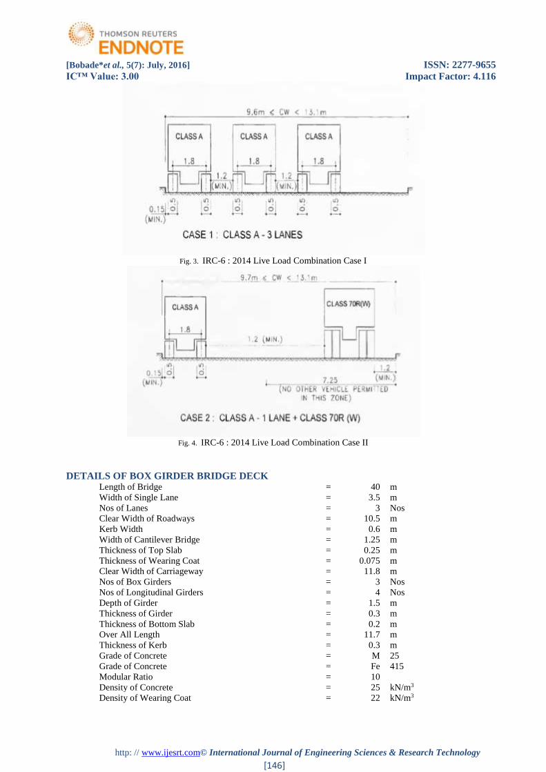
IRC-6 : 2014 Live Load Combination Case I (3 ClassA)
IRC-6 : 2014 Live Load Combination Case II (Class A + Class 70R(W))
RESULTS & DISCUSSIONS
The results are obtained and the presented in terms of critical structural response such a deflection, longitudinal
bending moment, torsional moment, shear force, and support reaction in the Box Girder Bridge deck Models
due to the applied wheel load. The variations of the critical structural response parameter due to changes of
skew angle are presented below.
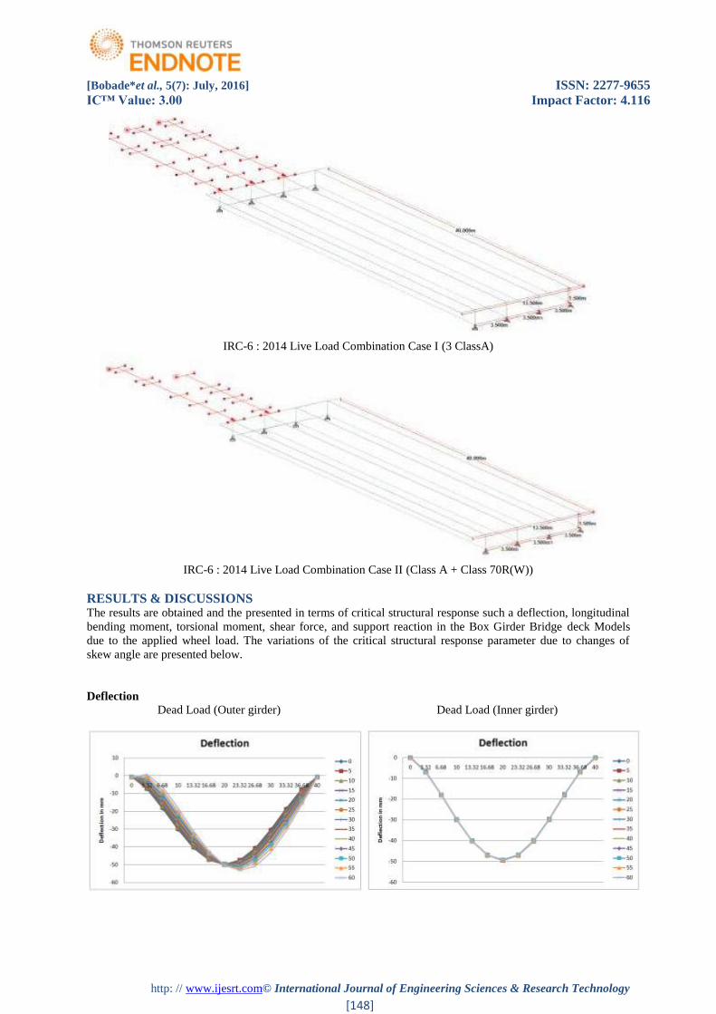
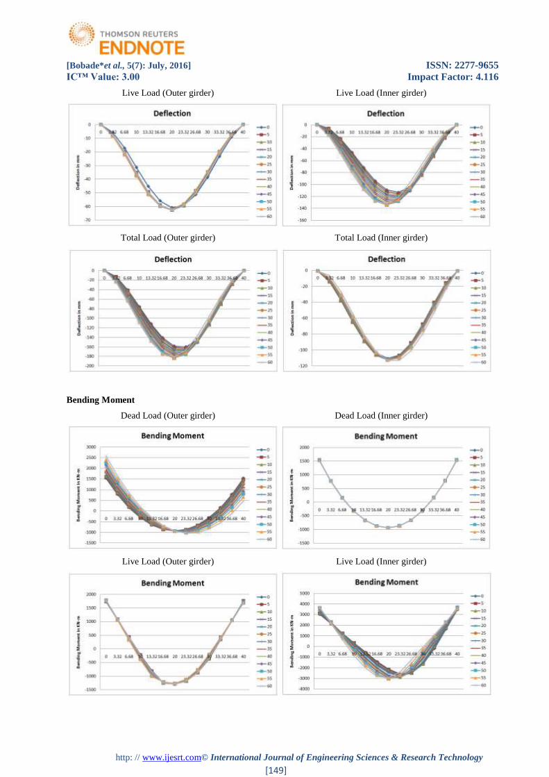
Deflection
Dead Load (Outer girder) Dead Load (Inner girder)
[Bobade*et al., 5(7): July, 2016] ISSN: 2277-9655
IC™ Value: 3.00 Impact Factor: 4.116
http: // www.ijesrt.com© International Journal of Engineering Sciences & Research Technology
[149]
Live Load (Outer girder) Live Load (Inner girder)
Total Load (Outer girder) Total Load (Inner girder)
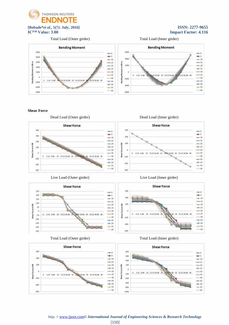
Bending Moment
Dead Load (Outer girder) Dead Load (Inner girder)
Live Load (Outer girder) Live Load (Inner girder)
[Bobade*et al., 5(7): July, 2016] ISSN: 2277-9655
IC™ Value: 3.00 Impact Factor: 4.116
http: // www.ijesrt.com© International Journal of Engineering Sciences & Research Technology
[150]
Total Load (Outer girder) Total Load (Inner girder)
Shear Force
Dead Load (Outer girder) Dead Load (Inner girder)
Live Load (Outer girder) Live Load (Inner girder)
Total Load (Outer girder) Total Load (Inner girder)
[Bobade*et al., 5(7): July, 2016] ISSN: 2277-9655
IC™ Value: 3.00 Impact Factor: 4.116
http: // www.ijesrt.com© International Journal of Engineering Sciences & Research Technology
[151]
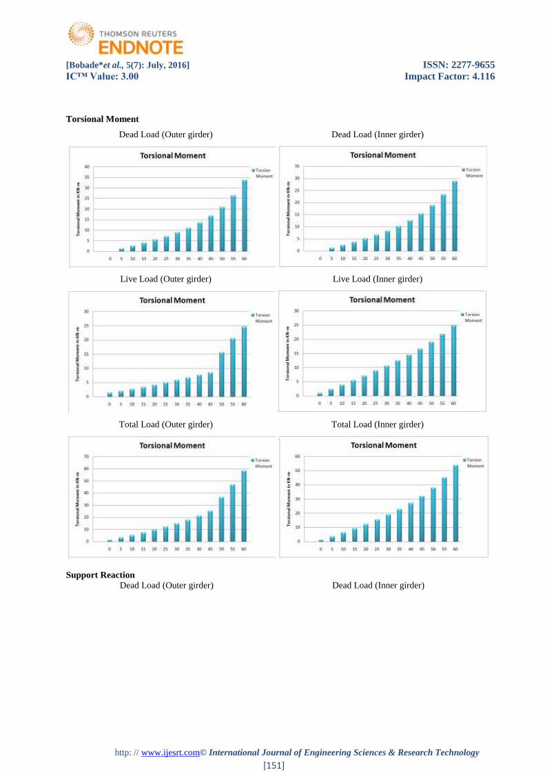
Torsional Moment
Dead Load (Outer girder) Dead Load (Inner girder)
Live Load (Outer girder) Live Load (Inner girder)
Total Load (Outer girder) Total Load (Inner girder)
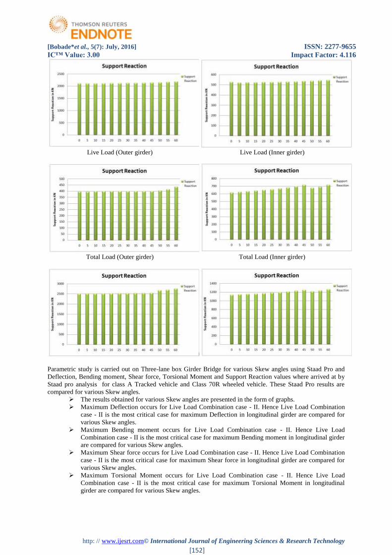
Support Reaction
Dead Load (Outer girder) Dead Load (Inner girder)
[Bobade*et al., 5(7): July, 2016] ISSN: 2277-9655
IC™ Value: 3.00 Impact Factor: 4.116
http: // www.ijesrt.com© International Journal of Engineering Sciences & Research Technology
[152]
Live Load (Outer girder) Live Load (Inner girder)
Total Load (Outer girder) Total Load (Inner girder)
Parametric study is carried out on Three-lane box Girder Bridge for various Skew angles using Staad Pro and
Deflection, Bending moment, Shear force, Torsional Moment and Support Reaction values where arrived at by
Staad pro analysis for class A Tracked vehicle and Class 70R wheeled vehicle. These Staad Pro results are
compared for various Skew angles.
The results obtained for various Skew angles are presented in the form of graphs.
Maximum Deflection occurs for Live Load Combination case - II. Hence Live Load Combination
case - II is the most critical case for maximum Deflection in longitudinal girder are compared for
various Skew angles.
Maximum Bending moment occurs for Live Load Combination case - II. Hence Live Load
Combination case - II is the most critical case for maximum Bending moment in longitudinal girder
are compared for various Skew angles.
Maximum Shear force occurs for Live Load Combination case - II. Hence Live Load Combination
case - II is the most critical case for maximum Shear force in longitudinal girder are compared for
various Skew angles.
Maximum Torsional Moment occurs for Live Load Combination case - II. Hence Live Load
Combination case - II is the most critical case for maximum Torsional Moment in longitudinal
girder are compared for various Skew angles.

[Bobade*et al., 5(7): July, 2016] ISSN: 2277-9655
IC™ Value: 3.00 Impact Factor: 4.116
http: // www.ijesrt.com© International Journal of Engineering Sciences & Research Technology
[153]
Maximum Support Reaction occurs for Live Load Combination case - II. Hence Live Load
Combination case - II is the most critical case for maximum Support Reaction in longitudinal girder
are compared for various Skew angles.
CONCLUSIONS
The comparative study was conducted based on the analytical modeling of simply supported RC Box Girder
Bridge for various Skew angles using Staad Pro. Based on this study Deflection occurs for Live Load
Combination case - II of various Skew angles result is increase by (1.750%) with increase in Skew angle are
compared. Bending moment occurs for Live Load Combination case - II of various Skew angles result is
increase by (1.525%) with increase in Skew angle are compared. Shear force occurs for Live Load Combination
case - II of various Skew angles result is increase by (1.376%) with increase in Skew angle are compared.
Torsional Moment occurs for Live Load Combination case - II of various Skew angles result is increase by
(135.36%) with increase in Skew angle are compared. Support Reaction occurs for Live Load Combination case
- II of various Skew angles result is increase by (0.001%) with increase in Skew angle are compared.
ACKNOWLEDGMENT
The journalist would like to prompt their sincere thanks to the KDK college of Engineering for giving Guidance
and technical support to get done this research.
REFERENCES
[1] Ibrahim S. I. Harba, (2011) “Effect of Skew Angle on Behavior of Simply Supported R. C. T-Beam
Bridge Decks”,ARPN Journal of Engineering and Applied Sciences, ISSN 1819-6608, VOL. 6, NO. 8,
AUGUST 2011, Iraq.
[2] Vikash Khatri, P. R. Maiti (2012). “Analysis of Skew Bridges Using Computational
Methods”,/International Journal Of Computational Engineering Research / ISSN: 2250–3005, IJCER |
May-June 2012 | Vol. 2 | Issue No.3 |628-636, India.
[3] Ansumankar, Vikash Khatri(2012) “Study on Effect of Skew Angle in Skew Bridges”, International
Journal of Engineering Research and Development e-ISSN: 2278-067X, p-ISSN: 2278-800X Volume 2,
Issue 12 (August 2012), PP. 13-18,India.
[4] Sindhu B.V, Ashwin K.N (2013) “Effect of Skew Angle on Static Behaviour of Reinforced Concrete
Slab Bridge”, IJRET: International Journal of Research in Engineering and Technology, eISSN: 2319-
1163 | pISSN: 2321-7308, pg no. 50-58, Nov-2013, India.
[5] L.A. Abozaid, Ahmed Hassan (2014) “Nonlinear Behaviour of a Skew Slab Bridge under Traffic
Loads”, World Applied Sciences Journal 30 (11): 1479-1493, 2014, ISSN 1818-4952, 2014, Egypt.
[6] Kamal Kumar Pandey, Savita Maru (2015), “Modelling of Skew Bridge Deck Slab by Grillage”,
International Journal of Engineering Research and General Science Volume 3, Issue 4, July-August,
2015, ISSN 2091-2730, pg no. 617-623, India.
[7] IRC:6-2014, “Standard Specifications and Code of Practice for Road Bridges Section : II Loads and
Stresses”.
[8] IRC:21-2000, “Standard Specifications and Code of Practice for Road Bridges Section : III Cement
Concrete (Plain and Reinforced)”.