Embed Size (px)
Citation preview

IOSR Journal of Mechanical and Civil Engineering (IOSR-JMCE)
e-ISSN: 2278-1684,p-ISSN: 2320-334X, Volume 11, Issue 4 Ver. V (Jul- Aug. 2014), PP 33-39 www.iosrjournals.org
www.iosrjournals.org 33 | Page
Parametric Studies of Low Velocity Impact on E-glass/Epoxy
using Ls-Dyna
Abdul Nazeer, (Assistant professor, Department of mechanical engineering SECAB Institute of engineering & Technology,
Bijapur, INDIA )
Abstract: To investigate the response of E-glass/epoxy laminated plates subjected to low velocity impact
loading. using nonlinear explicit finite element software LS-DYNA. The samples used for this study was 8 plies
laminated symmetric composites. These composites were characterized by three different stacking sequences
[0/90]2s, [-30/30]2s, [ 45/45]2s. Different parameter are considered here such as by varying the velocity,
orientation, boundary conditions etc. And the obtained results are compared against the experimental results.
Comparisons is made of finite element results to the experimental data obtained from the literature where the
contact force versus time graphs are obtained. Results indicate that the general shapes of the force versus time
curve histories are co-relate well with the experimental test data results. Thus this analysis work demonstrates
the accuracy and effectiveness of finite element simulation of low velocity impact test on laminated composite plate with LS-DYNA and predicting good simulation results with published journals for various parameters.
Keywords: Finite element analysis, Composite plates, Impact, Contact force, Ls Dyna
I. Introduction Composite laminates are used in many engineering applications Advance fibere reinforced material
with high sitffness and high strength such as carbon/epoxy graphite/epoxy and kevler/epoxy are now widely
used in as structural material in areospace industries and material transport purpose. The high-stiffness, high-
strength and low-density characteristics make composites highly desirable in primary and secondary structures
of both military and civilian aircraft. Besides the advantages of durability and reduced maintenance, composites afford the possibility of embedding sensors for on-board health monitoring Other imporant benefits are their low
co-efficent of thermal expansion and which inter-laminar stresses and their low elastic modulus which gives
high fiexibility.The relatively weak behavior of composite materials under localized impact has always been one
of the major weaknesses limiting their use unlike metals, polymeric matrix composites do not have the ability to
deform plastically to absorb the kinetic energy of the impactor. Composite structures are suspectable to the
impact loading such as handling loads and dropping which is one the major concerns in desiging composite-
made structures Impact-induced damage may arise during manufacture, maintenance and service operation. Low
velocity impact could cause significant damage, in terms of matrix cracking and delamination possibly fiber
breakage, fiber-pullout and other barely visible impact damages (BVID). Such damage is very difficult to detect
by naked eye and can lead to severe reductions in the stiffness and strength of the structures.
“Low-velocity impact analysis of composite laminates under initial in-plane load R. Tiberkak[3]
studided the Dynamic stress analysis carried out by the use of a constitutive equation of composite laminates without damage. Ceyla AKIN[1] presented the response of E-glass/epoxy laminated plates subjected to low
velocity impact loading. Impact tests were performed using a specially designed vertical drop-weight testing
machine. Zeuleyha Aslan[10] studied the in-plane dimensional effect of fiber-reinforced laminated composites
under low velocity impact oriented cross-ply E-glass/epoxy laminates studied. S. Ganapathy,[12] studied A 4-
noded, 48 d.o.f. doubly curved quadrilateral shell finite element based on Kirchhoff Love shell theory, is used in
the nonlinear finite element analysis to predict the damage of laminated composite cylindrical/spherical shell
panels subjected to low-velocity impact. M.V. Hosur[4] studied experimental investigation carried out to
determine the response of four different combinations of hybrid laminates to low-velocity impact loading using
an instrumented impact testing machine.K.S. Krishnamurthy[9] studied the impact force and the structural
response accounting for large deformations are examined for the case of a cylindrical curved panel. A.
Shokuhfar[11] developed Analysis and optimization of smart hybrid composite plates subjected to low-velocity impact using the response surface methodology (RSM). Ik Hyeon Choi[5] studied Low-velocity impact analysis
of composite laminates using linearized contact law. Shiuh-Chuan Her[6] studied The finite element analysis of
composite laminates and shell structures subjected to low velocity impact. Due to the anisotropy of composite
laminates and non-uniform distribution of stress under dynamic loading, the failure process of laminates is very
complex. The dynamic response of composite structures subjected to transient dynamic loading has been studied
in terms of analytical, numerical [1,2] and experimental and Finite element method works [5,4].
Parametric Studies of Low Velocity Impact on E-glass/Epoxy using Ls-Dyna
www.iosrjournals.org 34 | Page
In the present investigation, the LS-DYNA finite element software is used to calculate the transient
response of the impact on composite laminates,The numerical results are compared with those existing
literatures. The objective of this research is to study and conduct the analysis on E-glass/epoxy composite
laminated plate by clamping it both 4 side and 2 side, Contact force and center deflection are presented for
various parameters including velocity of impactor and stacking sequence of plate
Low Velocity: Low velocity impact is defined as a event which can treated as quasi-static, the upper limit of which can vary from one to tens of ms-1 depending on the target sitffness, material properties and the impactor’s
mass and stiffness
Contact force
The duration of an impact between two bodies occurs at a very short of period, normally within a few micro
seconds. The transient response of the impact is investigated on the basis of the following assumptions:
Frictionless between the impactor and composite structure.
Neglecting the damping affect in the composite structure.
Ignoring the gravity force during the impact period.
Rigid body for the impactor
A. Methodologies
A methodology describes different approaches to analysis the impact and the prediction of impact
induced damage by means of the finite-element method can be categorized into the following steps:
Analyzing the contact force between impacting mass and the plate element as a function of time.
This contact force as it depends on the relative approach of the two contacting bodies.
Applying the contact force to find the transient dynamic response of the impacted structure as a function of
position and time which depends on the mass and velocity of the impactor and the laminate characteristics
(geometry, boundary conditions, ply arrangement, elastic properties
The finite element model impact simulation is carried out using LSDYNA 971 as a solver.
Fig 1: A two side clamped plate Fig 2: A four side clamped plate
Here the analysis is carried out by varying the different parameters like velocity, orientation, boundary
condition etc. Majorly it is divided into two parts by boundary conditions one is by clamping two and other is by
clamping four side. The results shown below is for 2 side clamped condition by different velocities and
orientation
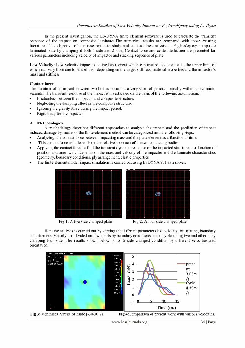
Fig 3: Vonmises Stress of 2side [-30/30]2s Fig 4:Comparison of present work with various velocities.
-1
0
1
2
3
4
5
0 5 10 15
present 3.03m/sCyela 4.35m/s
Lo
ad
(kN
)
Time (ms)

Parametric Studies of Low Velocity Impact on E-glass/Epoxy using Ls-Dyna
www.iosrjournals.org 35 | Page
Fig 5: Vonmises stresses of 2 side clamped [-45/45]2s Fig 6: comparison of present work with various
velocities.
Fig 7:Vonmises stresses of 2 side clamped [0/90]2s. Fig 8:comparison of present work with various velocities
So from the above result it can be seen that the maximum contact force is reached by increasing the
velocity of impactor. As the velocity increases the contact force is also increased, with respect to the orientation
the maximum contact force is found with lay up sequence of [-30/30].
Fig 9: Vonmises stresses of 4 side clamped [-30/30]2s Fig 10: Comparison of present work with various
velocities.

Parametric Studies of Low Velocity Impact on E-glass/Epoxy using Ls-Dyna
www.iosrjournals.org 36 | Page
Fig 11: Vonmises stresses of 4 side clamped[-45/45]2s Fig 12: comparison of present work with various
velocities
Fig 13: Vonmises stresses of 4 side clamped[0/90]2s Fig 14: Comparison of present work with various
velocities 4side [0/90]2s
The above figures (9,10,11,12,13,14) shows the results for second part of the analysis were the plate is
clamped from all four side. Here also it is observed that the maximum contact force is for velocity of 4.35m/s.
but with respect to orientation the maximum contact force is obtained for[-45/45] lay up because as it clamped
from all side and if orientation is at 45 degree it will have more stiffness and stable. With both part of analysis it
is observed that the plate with four side clamped is more stable than the plate with two side as the maximum
contact force is for 4-side clamped boundary condition. It is observed that in 2-side clamped condition the
negative velocity occur as the impactor impacts the plate, due to its elastic property the plate start bending due
to the bending the impactor move with plate. As the plate is clamped from all four side it will not deform as it
is clamped due to which perforation of impactor is more in four side clamped condition. As impactor impacts
the plate at zero time is point were the impactor just touches the plate as time increases the contact force
increases till it reaches the maximum value there after the plate looses its properties as the fiber in plate breakage take place due to which matrix delamination starts due to which the contact force curve starts falling,
the sipkes occurs in the curve due to sounds energy that takes place during impact. From the von mises stresses
plot for 2 side clamped it is observed the maximum stress at boundaries and in 4-side clamped the maximum
stress is just under impactor because in 2-side clamped due to its elastic behaviour and negative velocity the
bending of plate takes due to which stresses are induced the boundaries, where as in 4-side clamped condition as
it clamped from all side the structure is much stable and will not deform much due to which what ever stresses
are produced are just below the plate.
2 SIDE
Max. Contact
Force of Present
Work.(3.03m/s)
Max. Contact
Force of Present
Work.(4.35m/s)
Max Contact
Force of Cyela
Work
(3.03m/s)
Max Contact
Force of Cyela
Work (4.35 m/s)
Effective
stress
(V-M)
[-30/30]2s 3.5 KN 4.5 KN 2.8 4.1 KN 6.119e-2
[-45/45]2s 3.7 KN 4.5 KN 2.5 3.7 KN 9.503e-4
[0/90]2s 3.2 KN 4.1 KN 2.7 3.6 KN 6.672e-2
4 SIDE
[-30/30]2S 3.7 KN 4.7 KN 3.8 3.9 KN 4.219e-2
[-45/45]2s 3.9 KN 4.8 KN 3.8 4.9 KN 4.801e-1
[0/90]2s 4 KN 4.5 KN 4.1 4.3 KN 5.055e-2
-1
0
1
2
3
4
5
6
0 20 40
present 3.03m/s
Cyela 4.35m/s
Present 4.35m/s
Cyela3.03m/s
Lo
ad
(kN
)
Time (ms)

Parametric Studies of Low Velocity Impact on E-glass/Epoxy using Ls-Dyna
www.iosrjournals.org 37 | Page
All side clamped with orientation of [-30/30]2s
All side clamped with 3.03m/s All side clamped with 3.74m/s All side clamped with 4.35m/s
All side clamped with orientation of [-45/45]2s
All side clamped with 3.03m/s All side clamped with 3.74m/s All side clamped with 4.35m/s
All side clamped with orientation of [0/90]2s
All side clamped with 3.03m/s All side clamped with 3.74m/s All side clamped with 4.35m/s Fig 14:-Damages in bottom surface for clamped in four side sides samples a) [-30/30]2s, b) [-45/45]2s c)
[0/90]2s
Two side clamped with orientation of [-30/30]2s
Two side clamped with 3.03m/s Two side clamped with 3.74m/s Two side clamped with 4.35m/s

Parametric Studies of Low Velocity Impact on E-glass/Epoxy using Ls-Dyna
www.iosrjournals.org 38 | Page
Two side clamped with orientation of [-45/45]2s
Two side clamped with 3.03m/s Two side clamped with 3.74m/s Two side clamped with 4.35m/s
Two side clamped with orientation of [0/90]2s
Two side clamped with 3.03m/s Two side clamped with 3.74m/s Two side clamped with 4.35m/s
Fig 15:-Damages in bottom surface for clamped in two sides samples a) [-30/30]2s, b) [-45/45]2s c) [0/90]2s
Figure 14 shows the damage on the bottom surface of the plate when it is calmped from all four side
and figure 15 shows the damage on the bottom surface of plate when it is clamped at its two ends. The reveals
that, at the same energy levels, while there is maximum perforation is for four side clamped case, only partial
penetration occurs for two-side clamped material. It is observed that maximum stress are induced at boundary of
two sided clamped. This indicates that observed energy is much larger in four side clamped case. It is also
observed that for the four sides clamped situation, damage distribution is much larger at the same energy level
compared to that of the two side clamped case.
II. Conclusion Here different parameters were considered Clamping of boundary, varying the velocity of impactor,
changing the stacking sequence of plies. It was found that maximum contact force was occurred in 4-side clamp
boundary compare to 2-side clamp boundary because the plate is clamped from all side it will not deflect due to
impact so it will absorb maximum energy of impactor, where as the 2-side clamped plate will deflect with the
impactor and carries the energies of impactor towards the directions of impact and poses the elastic behaviour.
With respect to the above table and graphs we conclude that as the velocity of impactor increases the contact
force also increases. The analysis was carried out by varying the stacking sequence of piles and it was found that
the orienataion sequence of [-45/45] gives better results for 4-side clamped than other combination.
References [1]. Ceyla AKIN , Mehmet ŞENEL An Experimental Study Of Low Velocity Impact Response For Composite Laminated Plates Issn -
1302 30556.
[2]. Mi-Sun Rim, Eun-Ho Kim, In Lee ,2011 Low-Velocity Impact Characteristics Of Composite Plates With Shape Memory Alloy
Wires, Journal Of Theoretical And Applied Mechanics 49, 3, Pp. 841-857, Warsaw 2011
[3]. R. Tiberkak a, M. Bachene b, S. Rechak c,*, B. Necib, 2007 Damage prediction in composite plates subjected
[4]. to low velocity impact, elsevier Composite Structures 83 (2008) 73–82
[5]. Hosur.M.V, “Studies on the low-velocity impact resip/;ponse of woven hybrid composites” Composite Structures 67 (2005) 253–
262
[6]. Ik Hyeon Choi, “Low-velocity impact analysis of composite laminates using linearized contact law” Composite Structures 66
(2004) 125–132

Parametric Studies of Low Velocity Impact on E-glass/Epoxy using Ls-Dyna
www.iosrjournals.org 39 | Page
[7]. Shiuh-Chuan Her, “The finite element analysis of composite laminates and shell structures subjected to low velocity impact”
Composite Structures 66 (2004) 277–285
[8]. Parhi.P.K, Bhattacharyya.S.K and Shina.P.K:“Failure analysis of multiple delaminated composite plates due to bending and impact”
Bull. Mater. Sci., Vol. 24, No. 2, April 2001, pp. 143–149
[9]. Jeffery.S.N, Paine and Craig A. Rogers. Centre for intelligent material system and structure virginia Tech Blacksburg, Virginia
24061-0261 vol-5 july 1994
[10]. Krishnamurthy.K.S, “A parametric study of the impact response and damage of laminated cylindrical composite shells” Composites
Science and Technology 61 (2001) 1655–1669
[11]. ZuleyhaAslan “The response of laminated composite plates under low-velocity impact loading” Composite Structures 59 (2003)
119–127
[12]. Shokuhfar.A, “Analysis and optimization of smart hybrid composite plates subjected to low-velocity impact using the response
surface methodology (RSM)” Thin-Walled Structures 46 (2008) 1204– 1212
[13]. S. Ganapathy, K.P. Rao, Failure analysis of laminated composite cylindrical/spherical shell panels subjected to low-velocity impact
Computers and Structures 68 (1998) 627±641
[14]. LS-DYNA KEYWORD USER’S MANUAL”, Version-971, Livermore Software Technology Corporation,2006
[15]. http://www.lsdyna.com