Embed Size (px)
Citation preview

IJSRSET15143 | Received: 07 July 2015 | Accepted: 13 July 2015 | July-August 2015 [(1)4: 30-39]
© 2015 IJSRSET | Volume 1 | Issue 4 | Print ISSN: 2395-1990 | Online ISSN: 2394-4099
Themed Section: Engineering and Technology
1
Parametric Modelling of Standard & Modified Spur Gear Using
Pro-E & Analysing It by Actual Model
Dharini Trivedi
Department of Mechanical Engineering, Parul Institute of Engineering and Technology, Diploma Studies, Limda,
Ta. Waghodia, Vadodara, Gujarat, India
ABSTRACT
Modification and atomization parameters for spur gears is technique to generate the series of same kind of model
having different dimensions using standard models like PRO-E, CATIA etc. also it helpful to analyze the results
with actual model. Vibration induced by gears includes important data about gearbox condition. Dynamic modeling
of gear vibration used for increasing information about vibration generating mechanisms in gearboxes and dynamic
behavior of gearbox in the presence of some kind of gear defects. In this paper a six degree-of-freedom nonlinear
dynamic model including different gear errors and defects is developed for investigation of effects of tooth localized
defect and profile modifications on overall gear dynamics. Interactions between tooth modifications and profile
error are studied and the role of profile modification in dynamic response when a localized defect is incurred by a
tooth is shown. It is indicated that although profile modifications and profile errors are micro-geometrical, which
considerable effects on vibrations of gear pair also. Especially for the case of root relieved teeth that is shown to be
more effective in reduction of vibration in the presence of tooth localized defect. Finally, the simulation results are
compared with results from literature and the model. This paper introduces a method and steps based on Pro / E
parametric drive to forming involute modified spur gear, with the same way to automatically generate model of
base circle larger and smaller than root circle, simplify the procedures.
Keywords: Automization, Involute, Pro-E, Profile Modification, Spur gear.
I. INTRODUCTION
In engineering and technology the term “GEAR” is
defined as a machine element used to transmit motion
and power between rotating shafts by means of
progressive engagement of projections called teeth.
Gears operate in pairs, the smallest of the pair being
called “Pinion” and the larger the “gear”.
A. Spur Gears
In a pair of mating spur gears, the axis of the component
gears are parallel, that is, they are mounted on shafts
which are parallel to each other. The reference or the
pitch solid is a cylinder. The gear teeth are straight along
the length and are parallel to the axis. A rack is a
straight-sided gear and can be thought of as a spur gear
of infinite diameter.
The increasing demand for high tooth strength and high
load carrying capacity of gears leads to various methods
of improvements. One of the major method available till
now is “Profile Shift”. In gear technology it is known as
“Addendum Modification”. The amount by which the
addendum is increased or decreased is known as
“Addendum Modification”. The aim of addendum
modification is to avoid interference.
Figure 1: Spur gear and Rack and Pinion Mechanism Addendum
Modification
The function of a gear is to work smoothly while
transmitting motion or torque. For this the angular

International Journal of Scientific Research in Science, Engineering and Technology (ijsrset.com)
31
velocity ratio at all times should remain constant. This
aspect is explained here using various gear terminology
that are peculiar to gears.
Figure 2: Portion of involute spur gear
II. AUTOMIZATION
Using Pro-e, to automate the design process of common
parts & PRO/PROGRAM to create customized input
menus in an extremely powerful way to leverage
productivity. A few moments spent in pro-e &
PRO/PROGRAM can save hours in work load
redundancy. PRO/PROGRAMS are particularly useful
for businesses that want to productively use the expertise
of diverse employee groups or divisions.
Numerous methods can combine available components
in different ways to create multiple assembly variations.
One pro-e user might manually create each assembly &
modify the geometry as needed for different versions.
Another user might make interchange groups and/or
family tables of components that someone experienced
in pro-e could quickly alter. However, each of these
approaches depends on knowledge of how to correctly
retrieve & assemble components.
In contrast, PRO/PROGRAM users actually automate
parts assembly, reducing modification to a series of a
few selections. PRO/PROGRAM users create
PRO/PROGRAMS that manage features & components
to rebuild geometry so that even new users can make
complex changes. With PRO/PROGRAM fewer
employees can study more design iterations in less time
because of the inherent design knowledge captured in
the program. PRO/PROGRAM users modify feature
relations numerically or conditionally. Relations are
defined by equality or by comparison.
1) Equality: Equates a design variable to fixed
numerical values. For example, an equality relation
would set the pipe_length parameter as equal to
30mm (pipi_length=30).
2) Comparison: assigns value using If…Else…Endif
statements. An example follows:
IF pipe_dia=3
Pipe_length=5*pipe_dia
ENDIF
III. PROBLEM SUMMARY
The reasons of positive modification & the effects there
of are (1) Avoidance of undercutting. (2) Attainment of
a pre-determined center distance. (3) To increase the
strength at the root & flank of the teeth. (4) Betterment
of sliding & contact relations. (5) To shift the beginning
of the effective profile away from the base circle. The
highest sliding velocity & the maximum compressive
stress occurs the bottom of the tooth. Modeling for
different dimensions different models generated
separately in software but using automization only one
basic model is needed to generate series of same kind of
models having various dimensions. By which time of
modeling is reduced.
IV. LITERATURE REVIEW
Diametral pitch P: The number of teeth of a gear per
unit pitch diameter. The diametral pitch is hence the
number of teeth divided by the pitch diameter.
The product of the diametral pitch and the circular pitch
equals π.
p P = π
Figure 3: Actual size of the gear tooth for different diametric pitch

International Journal of Scientific Research in Science, Engineering and Technology (ijsrset.com)
32
Table 1: Standard diametric pitches
1 1.25 1.5 1.75 2 2.5 3
4 5 6 8 10 12 14
16 18 20 24 32 48 64
72 80 96 120
Actual tooth size for various diametral pitches is shown
in Figure 4. The diametral pitches are standardized and
these values are given Table 1.
Figure 4: Variation of tooth size with diametral pitch
Table 2: Standard modules in mm
0.3 0.4 0.5 0.6 0.7 0.8 1.0
1.25 1.5 1.75 2.0 2.25 2.5 3
3.5 4 4.5 5 5.5 6 6.5
7 8 9 10 11 12 13
14 15 16 18 20 22 24
26 28 30 33 36 39 42
45 50 Further increase is in terms of
5 mm
Figure 5: Crowning of the tooth to overcome edge
loading
In metric system, module is used instead of diametral
pitch. It is nothing but the inverse of diametral pitch.
The standard modules for which cutters are readily
available in the market are given in Table 2.
Figure 6: Meshing of one and two pairs of gear teeth
Module m: Pitch diameter divided by number of teeth.
The pitch diameter is usually specified in millimeters. m
= d/z
Figure 6 and 7 illustrate various terminologies one
comes across during meshing of gear teeth.
Figure 7: Action of tooth meshing
Pressure angle is also the angle between the line of
action and the common tangent.

International Journal of Scientific Research in Science, Engineering and Technology (ijsrset.com)
33
A. Gear Meshing
Figure 8: Gear Meshing
Having known various terminologies during meshing of
gears, how the contact points traverses is shown in
figure 8. It can be seen clearly during operation the
contact point demarked by red point is established on the
left hand side of the axis joining the centre of the gears
and moves to the right and vanishes. New contact is
established again at the left side. It moves along the
straight line known as line of action which is tangent to
both the base circles. The angle made by it with the
common tangent to the pitch circles at the pitch point is
known as the pressure angle. It can be noted that the line
of action passes through the pitch point which is the
point of intersection of the line connecting the centres of
the gears with the common tangent.
B. Gear Tooth Interference
Figure 9: Illustration of interference in gear
Figure 10: Gears in mesh showing portion of the tooth of pinion
digging into the gear tooth on the left
If the portion of the gear exists below the base circle,
then it results in interference and leads to undercutting
of the tooth. In Fig. 2.8 the shaded portion of the teeth
are below the base circles. They are going to cause
interference. In Fig.2.9 portion of the pinion tooth below
the gear tooth surface is seen. In practice this cannot
happen unless the part of the gear tooth is relieved of
material causing this interference. This is achieved by
the harder pinion tooth removing away the portion of the
gear tooth to avoid interference. Note that the tooth
portion below the base circle is not having involute
profile. Such a situation will arise when a gear with a
certain number of teeth mates with pinion having
number of teeth below a critical value.
V. METHODS OF ELIMINATION OF GEAR
TOOTH INTERFERENCE
In certain spur designs if interference exists, it can be
overcome by: (a) removing the cross hatched tooth tips
i.e., using stub teeth, (b) increasing the number of teeth
on the mating pinion, (c) increasing the pressure angle,
(d) tooth profile modification or profile shifting, (e)
increasing the centre distance as illustrated in Figure 11.
For a given gear, the interference can also the eliminated
by increasing the centre distance.
Figure 11: Method of elimination of interference in
spur gears
A. Minimum Number of Teeth on Pinion To Avoid
Interference For A Given Gear
Referring to Fig. 2.9, the involute profile doesn’t exist
beyond base circle. When the pinion rotates clockwise,
first and last point of contacts are e and g where the line
of action is tangent to the base circles.
Any part of the pinion tooth face extending beyond a
circle through g interferes with gear flank.

International Journal of Scientific Research in Science, Engineering and Technology (ijsrset.com)
34
The interference limits the permissible length of
addendum. As the diameter of the pinion is reduced, the
permissible addendum of larger gear becomes smaller.
Let the addendum height be k times the module i.e., km.
From the Figure 1, the maximum gear addendum circle
radius is:
(01)
Figure 12: Pinion and gear meshing shown by
equivalent circles
But, =
Substituting in equation (01) & simplifying
(02)
Substituting r1=mz1 & r2=mz2 in equation (02) &
rearranging
(03)
For a rack & pinion = & the equation (03) reduces to
= (04)
For full depth gears engaging with rack, minimum teeth
on the pinion to avoid interference is
= 31.9 = 32 for 14.50 pressure angle
= 17.097 = 17 for 200 pressure angle
= 13.657 = 14 for 22.50 pressure angle
rounded to integer value.
The equation (03) indicates that the minimum number of
teeth on pinion permissible and it depends on the gear
ratio and pressure angle.
From the practical consideration it is observed that rack
gear generation and hobbing process for lower value
than the one given earlier, a little undercutting takes
place and the strength of the gear is not affected. Hence,
corresponding minimum number of teeth are 27, 14 and
12 for 14.50, 200, and 22.50 instead of 32, 17 & 14.
B. Line of Action
In order to have smooth continuous rotation, the arc of
action should be greater than the circular pitch or line of
action or path of contact should be equal to or greater
than base pitch.
= (r2 + r1) sin ≥ p cos (05)
From which p ≤ (r2 + r1) tan (06)
And (07)
The line of action should be at least 1.4 times the
circular pitch for continuous action.
C. Contact Ratio
Referring to the Figure 13, the theoretical length of line
of action of any pair of true involute gears
AB= (08)
Contact ratio: is defined as the maximum number of
teeth in contact at any time. Higher the contact ratio
smoother will be gear operation
Contact ratio = (09)
Figure 13: various circles & line of action in a pair of
meshing gears.
International Journal of Scientific Research in Science, Engineering and Technology (ijsrset.com)
35
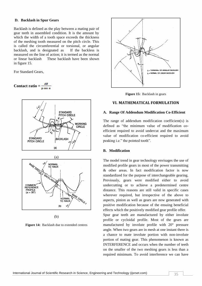
D. Backlash in Spur Gears
Backlash is defined as the play between a mating pair of
gear teeth in assembled condition. It is the amount by
which the width of a tooth space exceeds the thickness
of the meshing tooth measured on the pitch circle. This
is called the circumferential or torsional, or angular
backlash, and is designated as If the backless is
measured on the line of action; it is termed as the normal
or linear backlash These backlash have been shown
in figure 15.
For Standard Gears,
Contact ratio =
(a)
(b)
Figure 14: Backlash due to extended centres
Figure 15: Backlash in gears
VI. MATHEMATICAL FORMULATION
A. Range Of Addendum Modification Co-Efficient
The range of addendum modification coefficient(x) is
defined as “the minimum value of modification co-
efficient required to avoid undercut and the maximum
value of modification co-efficient required to avoid
peaking i.e.” the pointed tooth”.
B. Modification
The model trend in gear technology envisages the use of
modified profile gears in most of the power transmitting
& other areas. In fact modification factor is now
standardized for the purpose of interchangeable gearing.
Previously, gears were modified either to avoid
undercutting or to achieve a predetermined centre
distance. This reasons are still valid in specific cases
wherever required, but irrespective of the above to
aspects, pinion as well as gears are now generated with
positive modification because of the ensuing beneficial
effects which the positively modified gear profile offer.
Spur gear teeth are manufactured by either involute
profile or cycloidal profile. Most of the gears are
manufactured by involute profile with 20° pressure
angle. When two gears are in mesh at one instant there is
a chance to mate involute portion with non-involute
portion of mating gear. This phenomenon is known as
INTERFERENCE and occurs when the number of teeth
on the smaller of the two meshing gears is less than a
required minimum. To avoid interference we can have

International Journal of Scientific Research in Science, Engineering and Technology (ijsrset.com)
36
undercutting, but this is not a suitable solution as
undercutting leads to weakening of tooth at its base. In
this situation Modified gears are used. In modified gears
Cutter rack is shifted upwards or downwards.
There are two types of modified gears:
1. So gearing (x1+x2=zero)
2. S gearing (x1+x2 not equal to zero)
1). So gearing
The two components of the mating pair of gear receive
numerically equal modification Factors, but these two
factors are algebraically of opposite signs. Normally, the
pinion is provided with positive modification & the gear
with negative modification.
x1 + x2 = 0 or x2 = -x1
That is, the pinion is an S-plus gear & the gear is an S-
minus gear. The So-gearing is also known as the “long
& short addendum” system.
For this type of gearing, the number of teeth of pinion
Z1 is less than the practical limiting number of teeth to
avoid undercutting Zmin. Also, the sum of the teeth of
both the gears should be equal to or greater than twice
the limiting minimum number of teeth. That is:
Z1 + Z2 >= 2Zmin
2). S-gearing
S-gearing the sum of the profile modifications of the two
mating gears is not equal to zero. It is either positive or
negative.
Figure 16: Types of modified gearing
a) Normal gearing X1 = X2 = 0
Pressure angle α =
b) So-gearing X1 = -X2 = 0.5
Working pressure angle = α =
c) S-gearing X1 = X2 = 0
Working pressure angle = α =
However, the sum is positive in almost all cases in order
to take advantage of the beneficial effect of positive
modification mentioned before. Usually, the sum is so
divided that the pinion gets the bigger share of the
positive modification. Sometimes an S-plus pinion may
mate with a normal, unmodified gear. It all depends on
how the situation warrants it.
Fig.3.1 illustrates the different types of gearing. In an S-
gearing, several parameters change. These changes are
explained below along with the procedure for
determination of the relevant values. A) Determination
of the working pressure angle. B) Actual center distance
in an S-modified gearing.
Figure 17: Determination of working pressure angle
Figure18: Basic rack geometry
Referring figure 17 & 18,
Let, inv = Involute pressure angle
= Roll angle at p
= Pressure angle at p
r = Radius of the pitch circle

International Journal of Scientific Research in Science, Engineering and Technology (ijsrset.com)
37
m = Module
= Radius of the rolling circle
= 2.75m
p = Circular Pitch
=
= Large pressure angle
Addendum = = m
Top clearance = c = 0.25m
Dedendum = = m + c
= m + 0.25m
= 1.25m
Depth of tooth = h=
= (1 + 1.25)m
= 2.25m
Pitch base circle,
Involute pressure angle, (Ref figure 19)
inv
Number of teeth,
Figure 19: Involute Curve
C. For Standard Spur Gear
1) PINION
Ref figure 18,
1. Number of teeth ( )
2. Pitch circle diameter,
3. Tip circle diameter,
4. Root circle diameter,
2) GEAR
1. Number of teeth
( )
2. Pitch circle
diameter,
3. Tip circle
diameter,
4. Root circle
diameter,
5. Base circle
diameter,
5. Base circle diameter,
6. Tooth thickness on
pitch circle,
7. Center Distance,
6. Tooth thickness
on pitch circle,
7. Center Distance,
D. For Modified Spur Gear
Modification factor,
1) PINION
Ref figure 18,
1. Number of teeth ( )
2. Pitch circle
diameter,
3. Tip circle diameter,
4. Root circle
diameter,
5. Tooth thickness on
pitch circle,
6. Center Distance,
2) GEAR
1. Number of teeth ( )
2. Pitch circle
diameter,
3. Tip circle diameter,
4. Root circle
diameter,
5. Tooth thickness on
pitch circle,
6. Center Distance,
E. Manual Modelling of Spur Gear Tooth
Manually spur gear involute curve & gear tooth
thichness can be drawn in shown in figure 20,
Figure 20: Involute curve & gear tooth thickness

International Journal of Scientific Research in Science, Engineering and Technology (ijsrset.com)
38
VII. SPUR GEAR MODELING WITH PRO-E
Step: 1 Generating Involute Curve by an Equation
Step: 2 Create A Cylinder
Step: 3 Create Three Circles Representing The Major
Diameters
Step: 4 Create A Datum Point A Datum Curve
Step: 5 Create A Datum Evaluate Feature
Step:6 Mirror The Copied Involute Curve
Step: 7 Copy The Curve Again
Step: 8 Copy The Curve Again
Step: 9 Pattern The Cut.
Step: 10 Finish The Part.

International Journal of Scientific Research in Science, Engineering and Technology (ijsrset.com)
39
VIII. CONCLUSION & FUTURE SCOPE
This work is around in middle position. Basic study
about gear terminologies & also parametric analysis
related to standard spur gear as well as modified spur
gear is done and calculations for basic dimension are
also completed. From this concluded that using
AUTOMIZATION prametric 2D/3D models possible
which didn’t required comlex syntax of java. Toothed
gears and pinion shafts also possible using this technique
with involutes curves. Modified gears have high
performance, low weight and occupy less space. Very
simple layout is needed because their teeth are straight
rather than angular. It is much easier to produce them &
they will not fail or break easily. It’s cheaper to purchase
& to maintain.
The next half of research will begins with PRO-
PROGRRAMING for the spur gear modeled in PRO-E.
With the help of this Programming verity of gear models
are to be generated & mechanical analysis & mechanism
is to be done for gear pairs. From those observations for
gear pair most appropriate pair is to be selected which
we will manufacture in industry. Then comparison
between actual model & software based model is to be
done.
IX. REFERENCES
[1] Spitas, V., Costopoulos, Th. and Spitas, C., "Increasing the
Strength of Standard Involute Gear Teeth with Novel Circular
Root Fillet Design", American Journal of Applied Sciences, vol.
2, No. 6, pp. 1058-1064, 2005.
[2] Hiremagalur, Jagannath and Ravani, Behram, "Effect of Backup
Ratio on Root Stresses in Spur Gear Design", Mechanics Based
Design of Structures and Machines, vol. 32, No. 4, pp. 423-440,
2004.
[3] Beghini, M., Presicce, F. and Santus, C., "A Method to Define
Profile Modification of Spur Gear and Minimize the
Transmission Error", American Gear Manufacturer’s
Association, Technical Paper, pp. 1-9, 2004.
[4] Yi-Cheng Chen and Chung-Biau Tsay, "Stress Analysis of a
Helical Gear Set with Localized Bearing Contact", Finite
Elements in Analysis and Design, vol. 38, pp. 707-723, 2002.
[5] Chien-Hsing Li, Hong-Shun Chiou, Chinghua Hung, Yun-Yuan
Chang and Cheng-Chung Yen, "Integration of Finite Element
Analysis and Optimum Design on Gear Systems", Finite
Elements in Analysis and Design, vol. 38, pp. 179-192, 2002.
[6] Kapelevich, Alexander, L., and Kleiss, Roderick, E., "Direct
Gear Design for Spur and Helical Involute Gears", Gear
Technology, pp. 29-35, 2002.
[7] Parker, R. G., Vijayakar, S. M., and Imajo, T., "Non-Linear
Dynamic Response of a Spur Gear Pair: Modeling and
Experimental Comparison", Journal of Sound and Vibration,
vol. 237, No. 3, pp. 433-455, 2000.
[8] Simon, Vilmos, "FEM Stress Analysis in Hypoid Gears",
Mechanism and Machine Theor", vol. 35, pp. 1197-1220, 2000.
[9] Zhang, Y., Fang, Z., "Analysis of Tooth Contact and Load
Distribution of Helical Gears with Crossed Axes", Mechanism
and Machine Theory, vol. 34, pp. 41-57, 1999.
[10] Fredette L. and Brown M., "Gear Stress Reduction Using
Internal Stress Relief Features", Journal of Mechanical Design,
vol. 119, pp. 518-521, 1997
[11] Vijayarangan S. and Ganesan N., "Stress Analysis of Composite
Spur Gear Using the Finite Element Approach", Computers and
Structures, vol. 46, No. 5, pp. 869-875, 1993.
[12] Moriwaki, I., Fukuda, T., Watabe, Y., Saito, K., "Global Local
Finite Element Method (GLFEM) in Gear Tooth Stress
Analysis", Journal of Mechanical Design, vol. 115, pp. 1008-
1012, 1993.
[13] Handschuh, R., and Litwin, F. L., "A Method of Determining
Spiral Bevel Gear tooth Geometry for Finite Element Analysis",
NASA TPP-3096m AVSCOM TR -C-020, 1991.
[14] Chen, W., and Tsai, P., "Finite Element Analysis of an Involute
Gear Drive Considering Friction Effects", ASME Journal of
Engineering for Industry, vol. 111, pp. 94-100, 1989.
[15] Drago, R. J., and Uppaluri, B. R., "Large Rotorcraft
Transmission Technology Development Program, Vol I",
Technical Report (D210-11972- 1-VOL-1), Boeing Vertol Co.,
NASA Contract NAS3-22143) NASA CR-168116, 1983