Embed Size (px)
Citation preview
199
Parametric Developmentof Problem DescriptionsRoly Hudson
issue 02, volume 07international journal of architectural computing
200
Parametric Development of Problem DescriptionsRoly Hudson
This paper addresses the development of parametric models incontemporary architectural practice.A parametric model can beregarded as a representation of a solution space and in order tostructure this, a description of the problem is required.Architecturaldesign tasks are typically ill structured, the goals may not be definedand the means unknown. Moving from an incomplete problemdescription to a functional parametric model is a difficult task. In thispaper the aim is to demonstrate that through a combination ofknowledge acquisition and capture a parametric model can developfrom an incomplete problem description.This demonstration draws onexisting strands of design theory which are then used to outline atheoretical framework.This framework is then used to examine a casestudy of a live project and practical examples of the described theory inaction are given.The practical observations are the result of a casestudy involving the author as a participant and observer working withPopulous to develop a cladding geometry solution for Lansdowne RoadStadium in Dublin (now know as the AVIVA STADIUM).
201Parametric Development of Problem Descriptions
1. Introduction
The potential benefits of parametric tools in practice have been acclaimed,while simultaneously they are acknowledged as increasing the time requiredand the complexity of design tasks [1,2].The establishment of specialistgeometry and modeling groups within architectural practices [3,4,5]suggests an increase popularity of parametric design in architecturalpractice.The potential benefits of parametric tools are demonstrated by thework of these specialist groups. Parametric modeling has enabled thecapture and rationalisation of design intent [4,6]. Building design andconstruction documentation solutions have been developed using pre-rational and embedded rationale [7,8,9]. Multiple design alternatives can begenerated and evaluated in terms of various criteria and better solutionsselected [9]. Evaluation methods require different design representationswhich establish new links with other design disciplines [8,9]. Parametricdesign has enabled the exploration of complex geometry [10] and deeperexploration of traditional design methods [11].These examples demonstratethe potential of parametric design through descriptions of detailed stages ofdesign and documentation, but the means for arriving at that finalparametric model is often not explored. It is proposed here by systematicstudy of the process of parametric model development the observedcomplexity associated with the task can be reduced.
Some of the increased complexity and time required for parametricdesign can be attributed to the need for the understanding of thetechnology and learning of technical skills.The cognitive problem ofexplicitly constructing a solution space or a problem description isconsidered a more significant issue. Design tasks can be classified byunderstanding how complete the problem description is.Architecturalproblems typically can be described as ill structured tasks or even wickedproblems [12, 13].These types of problems consist of unknown goals andmeans, whereas well structured design tasks have goals that are clearlydefined and the possible means for pursuing those goals unambiguouslystated.
The process of developing parametric models has been described as“meta design” [14] or “design of design” by Mark Burry. Burry and Maher[15] suggest that everything needs to be considered or known at the outsetof a parametric design process. It is suggested here that the opposite maybe true, the process of developing a parametric model can begin withincomplete knowledge of the problem.A key part of the process istherefore obtaining knowledge of the problem and using this to structurethe problem space. Simon [12] identified that the structure of designproblems could develop through continuous modification of the problemspace.The task of finding and describing problems as well as solving themhas been identified and observed as one of the primary roles of aprofessional practitioner. Reflection in action [16] is the process of
conducting small mental experiments and evaluating the results in order togain understanding of a problem. Parametric tools can provide an explicitmeans of conducting reflective tests that enable knowledge acquisition inorder to develop and structure problem descriptions.
2. Case study description
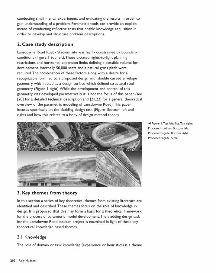
Lansdowne Road Rugby Stadium site was highly constrained by boundaryconditions (Figure 1 top left).These dictated rights-to-light planningrestrictions and horizontal expansion limits defining a possible volume fordevelopment. Internally 50,000 seats and a natural grass pitch wererequired.The combination of these factors along with a desire for arecognizable form led to a proposed design with double curved envelopegeometry which acted as a design surface which defined structural roofgeometry (Figure 1 right).While the development and control of thisgeometry was developed parametrically it is not the focus of this paper (see[20] for a detailed technical description and [21,22] for a general theoreticaloverview of the parametric modeling of Lansdowne Road).This paperfocuses specifically on the cladding design task (Figure 1bottom left andright) and how this relates to a body of design method theory.
3. Key themes from theory
In this section a series of key theoretical themes from existing literature areidentified and described.These themes focus on the role of knowledge indesign. It is proposed that this may form a basis for a theoretical frameworkfor the process of parametric model development.The cladding design taskfor the Lansdowne Road stadium project is examined in light of these keytheoretical knowledge based themes.
3.1 Knowledge
The role of domain or task knowledge (experience or heuristics) is a theme
� Figure 1.Top left: Site.Top right:
Proposed stadium. Bottom left:
Proposed façade. Bottom right:
Proposed façade detail.
202 Roly Hudson
that extends across much of the literature on problem solving andparametric design. Design itself has been defined as a “knowledge basedproblem solving activity” [17]. Practice based observations have identifiedthat design proceeds in a series of fragmented heuristic episodes [13].Newell, Shaw and Simon [23] define heuristic as “any principle procedure orother device contributes to the reduction in the search for a satisfactorysolution”. Successful application of heuristics to design tasks in architectureis dependant on an individual’s ability to select a suitable heuristic from amemory of previous design tasks.That memory can only be assembledthrough experience and the ability to select from it is governed by lateralidentification of similar characteristics between the current task and thosein the memory.
The ways in which domain knowledge can improve efficiency in designhave been identified [18]. Knowledge can be used to reduce the complexityof problems by ruling out ranges of possible solutions. Identification of keyparameters (those having greatest effect on design) from the multipleparameters reduces the amount of searching. Further reduction in searchcan be achieved by knowledge of valid ranges of key parameters.
It is proposed here that parametric tools can provide a representationfor capturing existing knowledge and acquiring new knowledge.The processof knowledge acquisition is regarded as equivalent to exploration.Exploration as a method of design has been discussed [17,24,25] as a meansof discovering new functionality, constraints and parameters and suggestinghow an existing problem description can be adjusted or discarded.Thereflective mental experiments observed by Schon [16] are examples ofimplicit exploration conducted by professionals aimed at gaining newknowledge of a problem. In this paper parametric design is regarded as anexplicit means of conducting these kind of experiments.
3.2 Design with knowledge representation
Gero describes how the design process can be intiated by case retrival orthrough the defintion of a prototype [19].The starting state is based onanalysis of the clients functional specifications and is retrieved from memoryor structured based on an existing solution or a solution from a similarproblem. Drawing an analogy between the current problem and previoussolutions in the designers memory has been described as case based [18],recall [25] and case retrieval [17].This is consistent with other theories ofdesign where heuristics have been observed in practice [13] to initiate adesign process.While some cases may be drawn from human memoryothers may come from more formal libraries like the repository of designpatterns [26,27], or the referents library described by Iordanva [28].
A prototype retrieved from memory is adapted to suit the newcondition.The adaptation is based on analysis and knowledge of the newcondition, the adapted prototype then becomes the starting point for the
203Parametric Development of Problem Descriptions
design problem.An initial solution can be synthesised and then evaluated tosee if it achieves the functions defined by the prototype.This tripartitemodel of analysis-synthesis-evaluation generates new knowledge of theproblem which either leads to reinterpretation of the analysis, synthesis of anew solution or reformulation of function and constraints of the problem.Other cyclic models have been proposed; propose-critique-modify [17] anddivergence-transformation-convergence [29], both can assist in developingan initial problem description.The development of the model thereforeprogresses cyclically and knowledge of the problem increases.At each loopthe appropriateness of the described functions and constraints can beassessed. Based on this assessment new knowledge is acquired which is thenused to change, omit or add goals and constraints.
4. Development of Lansdowne Road parametriccladding solution
The cladding design task for Lansdowne Road Stadium can be described asill structured.The only constant in the problem was the geometry of theunderlying structure (Figure 2a).The geometric, material and functional goalsof the task were undefined and the means for achieving those goalsunknown.The description of the development of the parametric model isorganized around a series of iterations each representing a chunk ofknowledge acquisition. Each of these iterations can be further decomposedinto a series of smaller lower level loops.
4.1. First iteration – initial studies
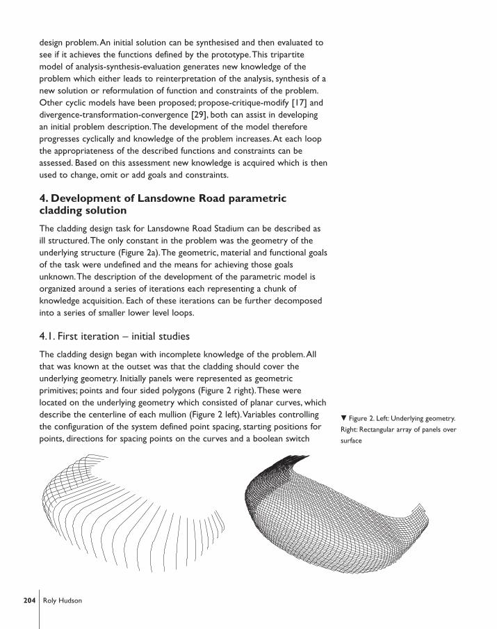
The cladding design began with incomplete knowledge of the problem.Allthat was known at the outset was that the cladding should cover theunderlying geometry. Initially panels were represented as geometricprimitives; points and four sided polygons (Figure 2 right).These werelocated on the underlying geometry which consisted of planar curves, whichdescribe the centerline of each mullion (Figure 2 left).Variables controllingthe configuration of the system defined point spacing, starting positions forpoints, directions for spacing points on the curves and a boolean switch
204 Roly Hudson
� Figure 2. Left: Underlying geometry.
Right: Rectangular array of panels over
surface
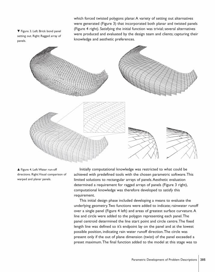
which forced twisted polygons planar.A variety of setting out alternativeswere generated (Figure 3) that incorporated both planar and twisted panels(Figure 4 right). Satisfying the initial function was trivial; several alternativeswere produced and evaluated by the design team and clients; capturing theirknowledge and aesthetic preferences.
Initially computational knowledge was restricted to what could beachieved with predefined tools with the chosen parametric software.Thislimited solutions to rectangular arrays of panels.Aesthetic evaluationdetermined a requirement for ragged arrays of panels (Figure 3 right),computational knowledge was therefore developed to satisfy thisrequirement.
This initial design phase included developing a means to evaluate theunderlying geometry.Two functions were added to indicate; rainwater runoffover a single panel (Figure 4 left) and areas of greatest surface curvature.Aline and circle were added to the polygon representing each panel.Thepanel centroid determined the line start point and circle centre.The fixedlength line was defined so it’s endpoint lay on the panel and at the lowestpossible position, indicating rain water runoff direction.The circle waspresent only if the out of plane dimension (twist) of the panel exceeded apreset maximum.The final function added to the model at this stage was to
� Figure 3. Left: Brick bond panel
setting out. Right: Ragged array of
panels.
� Figure 4. Left:Water run-off
directions. Right:Visual comparison of
warped and planar panels.
205Parametric Development of Problem Descriptions
layout all panel outlines in one plane with individual identification tags.Thiswas to establish and test some basic methods of processing modelinformation for production. Using this basic functionality parametric modelswere rapidly produced and examined, this formed the basis for decisionmaking. Decisions made introduced new knowledge and the problemdescription became clearer.This knowledge was then used or captured aspart of the model in the following iteration.
4.2 Second Iteration – manufacturing constraints
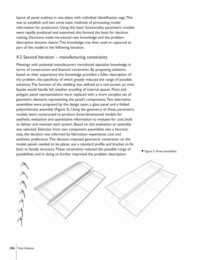
Meetings with potential manufacturers introduced specialist knowledge interms of construction and financial constraints. By proposing solutionsbased on their experience this knowledge provided a fuller description ofthe problem, the specificity of which greatly reduced the range of possiblesolutions.The function of the cladding was defined as a rain-screen, an innerfaçade would handle full weather proofing of internal spaces. Point andpolygon panel representations were replaced with a more complex set ofgeometric elements representing the panel’s components.Two alternativeassemblies were proposed by the design team, a glass panel and a foldedpolycarbonate assembly (Figure 5). Using the geometry of these, parametricmodels were constructed to produce three-dimensional models foraesthetic evaluation and quantitative information to evaluate for cost, bothto deliver and maintain each system. Based on this evaluation an assemblywas selected. Selection from two component assemblies was a heuristicstep, the decision was informed by fabrication experience, cost andaesthetic preference.This decision imposed geometric constraints on themodel, panels needed to be planar, use a standard profile and bracket to fixback to facade structure.These constraints reduced the possible range ofpossibilities and in doing so further improved the problem description.
� Figure 5. Panel assemblies.
206 Roly Hudson
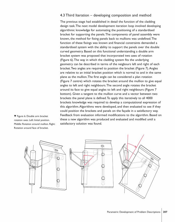
4.3 Third Iteration – developing composition and method
The previous stage had established in detail the function of the claddingdesign task.The next model development iteration loop involved developingalgorithmic knowledge for automating the positioning of a standardisedbracket for supporting the panels.The components of panel assembly wereknown, the method for fixing panels back to mullions was undefined.Thefunction of these fixings was known and financial constraints demanded astandardised system with the ability to support the panels over the doublecurved geometry. Based on this functional understanding a double armbracket system was proposed that incorporated two axes of rotation(Figure 6).The way in which the cladding system fits the underlyinggeometry can be described in terms of the neigbours left and right of eachbracket.Two angles are required to position the bracket (Figure 7).Anglesare relative to an initial bracket position which is normal to and in the sameplane as the mullion.The first angle can be considered a plan rotation(Figure 7 centre) which rotates the bracket around the mullion to give equalangles to left and right neighbours.The second angle rotates the bracketaround its face to give equal angles to left and right neighbours (Figure 7bottom). Given a tangent to the mullion curve and a vector between twobrackets the panel plane is defined.To apply this iteratively to all 4000brackets knowledge was required to develop a computational expression ofthis algorithm.Algorithms were developed, and then evaluated to see if theycould position the brackets and panels on the façade in a satisfactory way.Feedback from evaluation informed modifications to the algorithm. Based onthese a new algorithm was produced and evaluated and modified until asatisfactory solution was found.
207Parametric Development of Problem Descriptions
� Figure 6. Double arm bracket
rotation axes. Left: Initial position.
Middle: Rotation around mullion. Right:
Rotation around face of bracket.
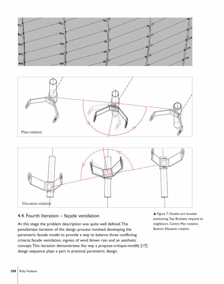
4.4. Fourth Iteration – façade ventilation
At this stage the problem description was quite well defined.Thepenultimate iteration of the design process involved developing theparametric facade model to provide a way to balance three conflictingcriteria; facade ventilation, ingress of wind blown rain and an aestheticconcept.This iteration demonstrates the way a propose-critique-modify [17]design sequence plays a part in practical parametric design.
208 Roly Hudson
Plan rotation
Elevation rotation
� Figure 7. Double arm bracket
positioning.Top: Brackets respond to
neighbours. Centre: Plan rotation.
Bottom: Elevation rotation.
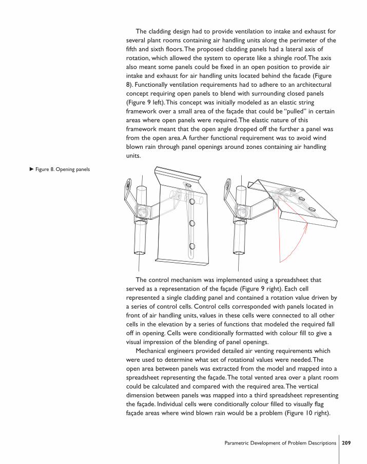
The cladding design had to provide ventilation to intake and exhaust forseveral plant rooms containing air handling units along the perimeter of thefifth and sixth floors.The proposed cladding panels had a lateral axis ofrotation, which allowed the system to operate like a shingle roof.The axisalso meant some panels could be fixed in an open position to provide airintake and exhaust for air handling units located behind the facade (Figure8). Functionally ventilation requirements had to adhere to an architecturalconcept requiring open panels to blend with surrounding closed panels(Figure 9 left).This concept was initially modeled as an elastic stringframework over a small area of the façade that could be “pulled” in certainareas where open panels were required.The elastic nature of thisframework meant that the open angle dropped off the further a panel wasfrom the open area.A further functional requirement was to avoid windblown rain through panel openings around zones containing air handlingunits.
The control mechanism was implemented using a spreadsheet thatserved as a representation of the façade (Figure 9 right). Each cellrepresented a single cladding panel and contained a rotation value driven bya series of control cells. Control cells corresponded with panels located infront of air handling units, values in these cells were connected to all othercells in the elevation by a series of functions that modeled the required falloff in opening. Cells were conditionally formatted with colour fill to give avisual impression of the blending of panel openings.
Mechanical engineers provided detailed air venting requirements whichwere used to determine what set of rotational values were needed.Theopen area between panels was extracted from the model and mapped into aspreadsheet representing the façade.The total vented area over a plant roomcould be calculated and compared with the required area.The verticaldimension between panels was mapped into a third spreadsheet representingthe façade. Individual cells were conditionally colour filled to visually flagfaçade areas where wind blown rain would be a problem (Figure 10 right).
� Figure 8. Opening panels
209Parametric Development of Problem Descriptions
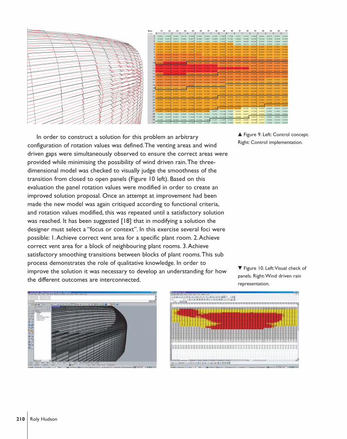
In order to construct a solution for this problem an arbitraryconfiguration of rotation values was defined.The venting areas and winddriven gaps were simultaneously observed to ensure the correct areas wereprovided while minimising the possibility of wind driven rain.The three-dimensional model was checked to visually judge the smoothness of thetransition from closed to open panels (Figure 10 left). Based on thisevaluation the panel rotation values were modified in order to create animproved solution proposal. Once an attempt at improvement had beenmade the new model was again critiqued according to functional criteria,and rotation values modified, this was repeated until a satisfactory solutionwas reached. It has been suggested [18] that in modifying a solution thedesigner must select a “focus or context”. In this exercise several foci werepossible: 1.Achieve correct vent area for a specific plant room. 2.Achievecorrect vent area for a block of neighbouring plant rooms. 3.Achievesatisfactory smoothing transitions between blocks of plant rooms.This subprocess demonstrates the role of qualitative knowledge. In order toimprove the solution it was necessary to develop an understanding for howthe different outcomes are interconnected.
210 Roly Hudson
Bays 81 82 83 84 85 86 87 88 89 90 91 92 93 94 95 96 97
ID Tag 0 1 2 3 4 5 6 7 8 9 0 1 2 3 4 5 60 13.0913 13.5427 13.5427 13.2719 13.0064 12.7463 12.4914 12.2416 11.9967 11.7568 11.5217 11.2912 11.0654 10.8441 10.6272 10.3615 10.1025
1 15.7096 16.2513 16.2513 15.9262 15.6077 15.2956 14.9897 14.6899 14.3961 14.1081 13.8260 13.5495 13.2785 13.0129 12.7526 12.4338 12.1230
2 18.8515 19.5015 19.5015 19.1115 18.7293 18.3547 17.9876 17.6278 17.2753 16.9298 16.5912 16.2594 15.9342 15.6155 15.3032 14.9206 14.5476
3 22.6218 23.4018 23.4018 22.9338 22.4751 22.0256 21.5851 21.1534 20.7303 20.3157 19.9094 19.5112 19.1210 18.7386 18.3638 17.9047 17.4571
4 27.1461 28.0822 28.0822 27.5206 26.9701 26.4307 25.9021 25.3841 24.8764 24.3789 23.8913 23.4135 22.9452 22.4863 22.0366 21.4857 20.9485
5 32.5754 33.6986 33.6986 33.0247 32.3642 31.7169 31.0826 30.4609 29.8517 29.2546 28.6696 28.0962 27.5342 26.9836 26.4439 25.7828 25.1382
6 39.0904 40.4384 40.4384 39.6296 38.8370 38.0603 37.2991 36.5531 35.8220 35.1056 34.4035 33.7154 33.0411 32.3803 31.7327 30.9393 30.1659
7 46.9085 48.5260 48.5260 47.5555 46.6044 45.6723 44.7589 43.8637 42.9864 42.1267 41.2842 40.4585 39.6493 38.8563 38.0792 37.1272 36.1990
8 53.6097 55.4583 55.4583 54.3492 53.2622 52.1969 51.1530 50.1299 49.1273 48.1448 47.1819 46.2383 45.3135 44.4072 43.5191 42.4311 41.3703
9 59.5664 61.6204 61.6204 60.3880 59.1802 57.9966 56.8367 55.6999 54.5859 53.4942 52.4243 51.3758 50.3483 49.3414 48.3545 47.1457 45.9670
10 64.9815 67.2222 67.2222 65.8778 64.5602 63.2690 62.0036 60.7636 59.5483 58.3573 57.1902 56.0464 54.9254 53.8269 52.7504 51.4316 50.1459
11 70.8889 73.3333 73.3333 71.8667 70.4293 69.0207 67.6403 66.2875 64.9618 63.6625 62.3893 61.1415 59.9187 58.7203 57.5459 56.1072 54.7046
12 77.3333 80.0000 80.0000 78.4000 76.8320 75.2954 73.7895 72.3137 70.8674 69.4500 68.0610 66.6998 65.3658 64.0585 62.7773 61.2079 59.6777
13 70.8889 73.3333 73.3333 71.8667 70.4293 69.0207 67.6403 66.2875 64.9618 63.6625 62.3893 61.1415 59.9187 58.7203 57.6317 56.2718 54.9414
14 64.9815 67.2222 67.2222 65.8778 64.5602 63.2690 62.0036 60.7636 59.5483 58.3573 57.1902 56.0464 54.9254 53.8269 52.9077 51.7337 50.5810
15 59.5664 61.6204 61.6204 60.3880 59.1802 57.9966 56.8367 55.6999 54.5859 53.4942 52.4243 51.3758 50.3483 49.3414 48.5710 47.5617 46.5666
16 54.6025 56.4853 56.4853 55.3556 54.2485 53.1635 52.1003 51.0583 50.0371 49.0364 48.0556 47.0945 46.1526 45.2296 44.5898 43.7260 42.8708
17 50.0523 51.7782 51.7782 50.7427 49.7278 48.7333 47.7586 46.8034 45.8673 44.9500 44.0510 43.1700 42.3066 41.4605 40.9349 40.1997 39.4684
18 45.8813 47.4634 47.4634 46.5141 45.5838 44.6721 43.7787 42.9031 42.0451 41.2042 40.3801 39.5725 38.7810 38.0054 37.5796 36.9578 36.3360
19 42.0578 43.5081 43.5081 42.6379 41.7852 40.9495 40.1305 39.3279 38.5413 37.7705 37.0151 36.2748 35.5493 34.8383 34.4993 33.9774 33.4522
20 38.5530 39.8824 39.8824 39.0848 38.3031 37.5370 36.7863 36.0505 35.3295 34.6229 33.9305 33.2519 32.5868 31.9351 31.6715 31.2373 30.7972
21 35.3403 36.5589 36.5589 35.8277 35.1112 34.4089 33.7208 33.0463 32.3854 31.7377 31.1029 30.4809 29.8713 29.2738 29.0755 28.7181 28.3530
22 32.3952 33.5123 33.5123 32.8421 32.1852 31.5415 30.9107 30.2925 29.6866 29.0929 28.5110 27.9408 27.3820 26.8344 26.6922 26.4021 26.1028
23 29.6956 30.7196 30.7196 30.1052 29.5031 28.9131 28.3348 27.7681 27.2127 26.6685 26.1351 25.6124 25.1002 24.5982 24.5043 24.2729 24.0311
24 27.2210 28.1597 28.1597 27.5965 27.0445 26.5036 25.9736 25.4541 24.9450 24.4461 23.9572 23.4780 23.0085 22.5483 22.4958 22.3154 22.1239
25 24.9526 25.8130 25.8130 25.2968 24.7908 24.2950 23.8091 23.3329 22.8663 22.4089 21.9608 21.5215 21.0911 20.6693 20.6519 20.5158 20.3680
26 22.8732 23.6619 23.6619 23.1887 22.7249 22.2704 21.8250 21.3885 20.9607 20.5415 20.1307 19.7281 19.3335 18.9468 18.9591 18.8613 18.7515
27 20.9671 21.6901 21.6901 21.2563 20.8312 20.4145 20.0063 19.6061 19.2140 18.8297 18.4531 18.0841 17.7224 17.3679 17.4051 17.3402 17.2633
28 19.2198 19.8826 19.8826 19.4849 19.0952 18.7133 18.3391 17.9723 17.6128 17.2606 16.9154 16.5771 16.2455 15.9206 15.9784 15.9418 15.8932
29 17.6182 18.2257 18.2257 17.8612 17.5040 17.1539 16.8108 16.4746 16.1451 15.8222 15.5058 15.1956 14.8917 14.5939 14.6687 14.6562 14.6318
30 16.1500 16.7069 16.7069 16.3728 16.0453 15.7244 15.4099 15.1017 14.7997 14.5037 14.2136 13.9293 13.6508 13.3777 13.4664 13.4742 13.4706
31 14.8042 15.3147 15.3147 15.0084 14.7082 14.4140 14.1258 13.8432 13.5664 13.2950 13.0291 12.7686 12.5132 12.2629 12.3626 12.3876 12.4015
� Figure 9. Left: Control concept.
Right: Control implementation.
� Figure 10. Left:Visual check of
panels. Right:Wind driven rain
representation.
4.5 Fifth iteration – information issue
The final iteration in developing the parametric model for the cladding ofLansdowne Road involved the acquisition of knowledge relating to the tasksof the cladding engineers, and the format of construction documentationneeded to support this.This aspect of the design process was incorporatedinto the parametric model to enable design adjustment and instant updateof construction data. Contractually the cladding engineers provided aguarantee for the façade, they therefore needed to take responsibility forspecifying manufacturing documentation. In order to do this they producedshop drawings and computer models of the façade components which thearchitectural design team checked. In order to do this they rebuilt thecladding geometry with their own software and incorporated their owndetails.The architectural design team was able to provide a writtendescription of how to regenerate the geometry. Geometric and numericdata extracted from the architects parametric model and also issued, usingthis the cladding reconstructed their own model of the façade system.
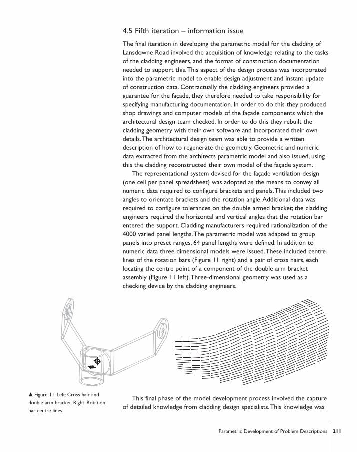
The representational system devised for the façade ventilation design(one cell per panel spreadsheet) was adopted as the means to convey allnumeric data required to configure brackets and panels.This included twoangles to orientate brackets and the rotation angle.Additional data wasrequired to configure tolerances on the double armed bracket; the claddingengineers required the horizontal and vertical angles that the rotation barentered the support. Cladding manufacturers required rationalization of the4000 varied panel lengths.The parametric model was adapted to grouppanels into preset ranges, 64 panel lengths were defined. In addition tonumeric data three dimensional models were issued.These included centrelines of the rotation bars (Figure 11 right) and a pair of cross hairs, eachlocating the centre point of a component of the double arm bracketassembly (Figure 11 left).Three-dimensional geometry was used as achecking device by the cladding engineers.
This final phase of the model development process involved the captureof detailed knowledge from cladding design specialists.This knowledge was
� Figure 11. Left: Cross hair and
double arm bracket. Right: Rotation
bar centre lines.
211Parametric Development of Problem Descriptions
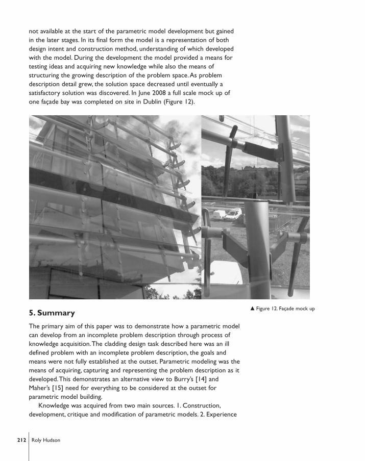
not available at the start of the parametric model development but gainedin the later stages. In its final form the model is a representation of bothdesign intent and construction method, understanding of which developedwith the model. During the development the model provided a means fortesting ideas and acquiring new knowledge while also the means ofstructuring the growing description of the problem space.As problemdescription detail grew, the solution space decreased until eventually asatisfactory solution was discovered. In June 2008 a full scale mock up ofone façade bay was completed on site in Dublin (Figure 12).
5. Summary
The primary aim of this paper was to demonstrate how a parametric modelcan develop from an incomplete problem description through process ofknowledge acquisition.The cladding design task described here was an illdefined problem with an incomplete problem description, the goals andmeans were not fully established at the outset. Parametric modeling was themeans of acquiring, capturing and representing the problem description as itdeveloped.This demonstrates an alternative view to Burry’s [14] andMaher’s [15] need for everything to be considered at the outset forparametric model building.
Knowledge was acquired from two main sources. 1. Construction,development, critique and modification of parametric models. 2. Experience
212 Roly Hudson
� Figure 12. Façade mock up
of specialists working on the project.As the project progressed the amountof knowledge and therefore model complexity increased, while the solutionspace was reduced in size.A reduced solution space and well describedproblem made finding satisfactory solutions more efficient, however otherpossible solutions may have been overlooked by the nature of the heuristicdesign process.
The first iteration illustrates starting a design process using assumptionsbased on incomplete problem descriptions.The task did not begin byretrieval of a similar project from memory or by application a heuristic.Instead the project can be seen as starting as a series of reflectiveexperiments described by Schön [16] however, in this case the experimentswere external rather than internal.These were in the form of quicklyconstructed models, with few constraints that were designed to examinethe problem in order to further the limited understanding of it and topotentially change the context.The initial models represented panels assimple polygons; variables provided flexible positioning. Simple evaluationprovided the potential to make reasoned changes to the underlyinggeometry, in this way a problem description began to emerge.
The second phase involved a reduction in the size of solution space byincorporating aspects of specialist manufacturing knowledge. Involvement ofmanufacturers in the process imposed heuristics which constrained therange of solutions.These impositions reduced the range of possiblesolutions by constraining geometric options. By applying a known problemstructure the size of solution space is reduced.This formalist response to aproblem aligns with a more rational view of design such as that describedby Simon [12] and Newell et al. [23]. However, Simon also proposed thatproblem structures could develop through continuous modification ofproblem space.Application of heuristic approach at this stage developed butdid not complete the problem description.
The next phase illustrated how the model itself provides a way ofdeveloping knowledge.The function of the bracket was known, what wasrequired was the means of expressing this in an algorithm to position panelsaround the whole building. Defining this was a cyclic process where theproblem was initially analysed, the proposed solution synthesised, this was thenevaluated by testing it with the known parts of the model. Following iterationsare more accurately described as propose-critique-modify [17] as the feedbackfrom the first evaluation informs the way the following proposal is defined.
The penultimate phase provides an explicit example of how propose,critique and modify can be also be applied to find a solution when aproblem is well defined.This involved balancing conflicting criteria toprovide facade ventilation.The final iteration of the cladding design processillustrates how the working methods or knowledge can become part of theparametric model.The method for communicating information to facadesub-contractors was not known at the start of the design process. However,
213Parametric Development of Problem Descriptions
some basic construction documentation procedures were tested.Thesewere modified once a detailed description of data formats was developed.
6. Conclusions
The case study demonstrates that it is possible to use parametric modelingto develop problem descriptions.This can be achieved with a range oftheoretical approaches, which can offer both expansive and reductivemethods. Expansive methods rely on exploration to find problemdescriptions. Reductive methods apply known problem structures orheuristics (which may be retrieved from memory or a library), these imposeconstraint, defining a problem description and reducing the range of possiblesolutions.Any problem description whether discovered or imposed willrequire improvement, the case study demonstrates how this can beachieved through a cyclical procedure of propose, critique and modify.
On a practical level, developing problem descriptions with parametricdesign requires working in a way where early models are quicklyconstructed and treated as disposable.They should be discarded when theydo not yield useful results and rebuilt. In this way the rigid structure of theparametric model will not restrict design direction. Later as the problemdescription becomes clearer it may be possible to develop a more refinedand stable model foundation onto which more disposable modules can beplugged in, tested and further developed. Use of placeholders which definesimplified versions or approximate guesses (like the initial panel models) willallow modeling to progress with incomplete knowledge. Based on thesedesign decisions can be made, as knowledge becomes available placeholderscan be substituted for more precise descriptions.
Acknowledgements
The author wishes to thank Populous and Bentley Systems for their supportwith this project.
References1. Aish, R., & Woodbury, R. Multi level interaction in parametric design, Lecture notes
in computer science, 2005, 3638, 151–162.
2. Woodbury, R., & Marques, D. Using rule based selection to support change inparametric cad models, Lecture notes in computer science, 2006, 4073, 230–235.
3. Peters, B., & De Kestelier, X.The work of the specialist modelling group, in:Sarhang, R., & Sharp, J. eds, Proceedings of bridges London,Tarquin Publications,London, 2006, 9–12.
4. Glymph, J., Shelden, D., Ceccato, C.,Mussel, J., & Schober, H.A parametric strategyfor freeform glass structures using quadrilateral planar facets. Automation inconstruction, 2004. 13(2), 187–202.
5. Hesselgren, L., Charitou, R., & Dritsas, S.The Bishopsgate tower case study.International journal of architectural computing, 2007, 5(1), 62-81.
6. Shelden, D. Digital surface representation and the constructibility of gehry’s
214 Roly Hudson
architecture. Ph.D. thesis, Massachusetts Institute of Technology, 2002.
7. Peters, B.The Smithsonian courtyard enclosure. in: Do, E., Kalisperis, L., Kolarevic, B.,& Pinet, C. eds, The association of computer-aided design in architecture, 2007, 74–83.
8. Whitehead, H. Laws of Form. in Kolarevic, B. (ed), Architecture in the Digital Age –design and manufacturing.Taylor and Francis,Abingdon. 2003, 81-100.
9. Whitehead, H. & Peters, B. Geometry form and complexity. Littlefield, D. (ed),Space craft: developments in architectural computing. RIBA, London, 2008, 20-33.
10. Gun, O.Y. Composing bits of surfaces in architectural practice. in:.Kieferle J.B.Ehlers K. (ed), Education in computer aided architectural design in europe, KanneGraphischer Betrieb, Frankfurt, Germany, 2007, 859-868.
11. Dritsas, S., & Becker, M. Research and design in shifting from analog to digital. in:Do, E., Kalisperis, L., Kolarevic, B., & Pinet, C. eds, The association of computer-aideddesign in architecture, 2007, 56-65.
12. Simon, H.A.The structure of ill structured problems. Artificial intelligence, 1973,4(3), 181–201.
13. Rowe, P.G. Design thinking.The MIT Press , Cambridge Massachusetts, 1987.
14. Burry, M. Between intuition and process: Parametric design and rapidprototyping. in: Kolarevic B, (ed), Architecture in the digital age – design andmanufacturing.Taylor and Francis,Abingdon, 2003, 147-162.
15. Maher,A.The parametric bridge. Selfridges Birmingham UK. in: Chaszar,A. (ed),Blurring the lines.Wiley, London, 2006, 76-81.
16. Schön, D.A. The reflective practitioner : how professionals think in action.Ashgate,Aldershot, 1991.
17. Chandrasekaran, B. Design problem solving:A task analysis. AI magazine, 1990,11(4), 59–71.
18. Motta, E., & Zdrahal, Z. Parametric design problem solving. Open University,doi=10.1.1.26.8464, 1996.
19. Gero, J. Design prototypes:A knowledge representation schema for design. AImagazine, 1990. 11(4), 26–36.
20. Shepherd, P., & Hudson, R. 2007. Parametric definition of Landowne roadstadium. in: International association of shell and spatial structures,Venice, Italy,2007,CD-ROM.
21. Hudson, R. Frameworks for practical parametric design in architecture. in:Pottman, H., Hofer, M. & Kilian,A. (eds), Advances in architectural geometry.Vienna,Austria, 2008,17-20.
22. Hudson, R. Frameworks for practical parametric design in architecture. in: Muylle,M. (ed), Education in computer aided architectural design in Europe.Antilope,Antwerp, Belgium. 2008, 847-854.
23. Newell,A, Shaw, J.C., & Simon, H.A. Elements of a theory of human problem solving.Rand Corporation. Santa Monica, 1957.
24. Kilian,A. Design exploration through bidirectional modeling of constraints. Ph.D. thesis,Massachusetts Institute of Technology, Cambridge Massachusetts, 2006.
25. Woodbury, R.F., & Burrow,A.L.Whither design space? Artificial intelligence forengineering design, analysis and manufacturing, 2006, 20(2), 63–82.
26. Woodbury, R.,Aish, R., & Kilian,A. Some patterns for parametric modeling. in:Do, E., Kalisperis, L., Kolarevic, B., & Pinet, C. eds, The association of computer-aideddesign in architecture, 2007, 222-229.
27. www.designpatterns.ca/. [21.08.2008].
28. Iordanova, I.Teaching digital design exploration: Form follows ... International
215Parametric Development of Problem Descriptions

Journal of Architectural Computing, 2007, 5(4), 685-702.
29. Jones, J. C. Design methods.Van Nostrand Reinhold, New York, 1992.
216 Roly Hudson
Roly HudsonUniversity of Bath, Department of Architecture and Civil Engineering,Claverton Down, Bath, BA2 7AY